EP1322260B1 - Minimally-invasive annuloplasty repair segment delivery template system - Google Patents
Minimally-invasive annuloplasty repair segment delivery template system Download PDFInfo
- Publication number
- EP1322260B1 EP1322260B1 EP01975785A EP01975785A EP1322260B1 EP 1322260 B1 EP1322260 B1 EP 1322260B1 EP 01975785 A EP01975785 A EP 01975785A EP 01975785 A EP01975785 A EP 01975785A EP 1322260 B1 EP1322260 B1 EP 1322260B1
- Authority
- EP
- European Patent Office
- Prior art keywords
- template
- holder
- shape
- repair segment
- combination
- Prior art date
- Legal status (The legal status is an assumption and is not a legal conclusion. Google has not performed a legal analysis and makes no representation as to the accuracy of the status listed.)
- Expired - Lifetime
Links
Images


Classifications
-
- A—HUMAN NECESSITIES
- A61—MEDICAL OR VETERINARY SCIENCE; HYGIENE
- A61F—FILTERS IMPLANTABLE INTO BLOOD VESSELS; PROSTHESES; DEVICES PROVIDING PATENCY TO, OR PREVENTING COLLAPSING OF, TUBULAR STRUCTURES OF THE BODY, e.g. STENTS; ORTHOPAEDIC, NURSING OR CONTRACEPTIVE DEVICES; FOMENTATION; TREATMENT OR PROTECTION OF EYES OR EARS; BANDAGES, DRESSINGS OR ABSORBENT PADS; FIRST-AID KITS
- A61F2/00—Filters implantable into blood vessels; Prostheses, i.e. artificial substitutes or replacements for parts of the body; Appliances for connecting them with the body; Devices providing patency to, or preventing collapsing of, tubular structures of the body, e.g. stents
- A61F2/02—Prostheses implantable into the body
- A61F2/24—Heart valves ; Vascular valves, e.g. venous valves; Heart implants, e.g. passive devices for improving the function of the native valve or the heart muscle; Transmyocardial revascularisation [TMR] devices; Valves implantable in the body
- A61F2/2442—Annuloplasty rings or inserts for correcting the valve shape; Implants for improving the function of a native heart valve
- A61F2/2445—Annuloplasty rings in direct contact with the valve annulus
-
- A—HUMAN NECESSITIES
- A61—MEDICAL OR VETERINARY SCIENCE; HYGIENE
- A61F—FILTERS IMPLANTABLE INTO BLOOD VESSELS; PROSTHESES; DEVICES PROVIDING PATENCY TO, OR PREVENTING COLLAPSING OF, TUBULAR STRUCTURES OF THE BODY, e.g. STENTS; ORTHOPAEDIC, NURSING OR CONTRACEPTIVE DEVICES; FOMENTATION; TREATMENT OR PROTECTION OF EYES OR EARS; BANDAGES, DRESSINGS OR ABSORBENT PADS; FIRST-AID KITS
- A61F2/00—Filters implantable into blood vessels; Prostheses, i.e. artificial substitutes or replacements for parts of the body; Appliances for connecting them with the body; Devices providing patency to, or preventing collapsing of, tubular structures of the body, e.g. stents
- A61F2/02—Prostheses implantable into the body
- A61F2/24—Heart valves ; Vascular valves, e.g. venous valves; Heart implants, e.g. passive devices for improving the function of the native valve or the heart muscle; Transmyocardial revascularisation [TMR] devices; Valves implantable in the body
- A61F2/2442—Annuloplasty rings or inserts for correcting the valve shape; Implants for improving the function of a native heart valve
- A61F2/2466—Delivery devices therefor
Definitions
- the present invention relates generally to medical devices and particularly to a holder for delivering annuloplasty repair segments or rings especially for use in minimally-invasive surgeries.
- annuloplasty ring or repair segments refers to any generally elongated structure used in annulus repair, whether straight or curved.
- annuloplasty ring is conventionally understood to provide either a complete or substantially complete loop sized to correct a misshapen and or dilated native annulus.
- a partial ring or even a straight repair segment may be used around just a portion of the annulus, such as around the posterior edge.
- annuloplasty repair segment as used herein is intended to encompass all of such structures.
- annuloplasty repair devices are typically suture-permeable, the use of the invention to implant other structures which are attached to the annulus without passage of sutures therethrough is also contemplated.
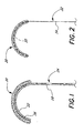
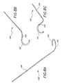
- FIG. 1 A first embodiment of the present invention is illustrated in Figure 1 in which an annuloplasty repair segment 20 is attached to a curved template portion 22 of a delivery holder 24.
- the annuloplasty repair segment 20 is flexible and conforms to the curved portion 22 by virtue of a plurality of attaching sutures 26, or other similar expedient.
- the holder 24 comprises the curved portion 22 defining a distal end, and a generally straight, elongated shaft portion 28 defining a proximal end.
- the shaft 28 may be flexible or rigid.
- the curved portion 22, on the other hand, is highly flexible, preferably elastic.
- curved portion 22 may be formed of a biocompatible metal such as stainless-steel or Elgiloy, or from a super-elastic material such as Nitinol.
- the material used for the curved portion 22 may be the same as that used for the shaft portion 28, or the two portions may be formed of different material and connected using conventional means. The usage of the holder 24 will be described below with respect to Figures 3A-3C.
- Figure 2 illustrates an alternative embodiment of the present invention similar to that shown in Figure 1, with an annuloplasty repair segment 20 supported on a curved wire-like template portion 30 of a holder 32.
- the holder 32 comprises the wire-like template portion 30 on the distal end, and a shaft portion 34 on the proximal end.
- the curved wire-like portion 30 passes through the body of the annuloplasty repair segment 20 to secure it thereto.
- the annuloplasty repair segment 20 must be sufficiently permeable for the wire-like portion 30 to pass therethrough.
- the annuloplasty repair segment 20 comprises an elastic inner core (not shown) surrounded by a tubular fabric covering 36.
- the wire-like portion 30 may therefore be passed between the inner core and the fabric covering 36, or may even be embedded within the inner core for a more secure coupling.
- the inner core may take a number of forms, including a solid metal rod such as titanium, a metal rod in combination with a silicone sleeve, or a silicone rod.
- Various other annuloplasty repair segment constructions are well-known in the art, and are incorporated herein.
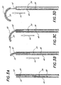
- Figures 3A-3C illustrate a series of positions of the combined annuloplasty repair segment 20 and holder 24 of Figure 1 being delivered through a delivery tube 40, such as a cannula or catheter. It should be understood that the same operation applies to the combined ring 20 and holder 34 shown in Figure 2.
- the delivery tube 40 comprises a proximal end (not shown) and an open distal end 42.
- the combined annuloplasty repair segment 20 and holder 24 are located as shown adjacent the distal end 42, or are advanced into that positioned through the tube 40. It should be noted that the curved template portion 22 on the distal end of the holder 24 (and the attached ring 20) assumes a straightened or elongate configuration when located within the tube 40.
- the distal end 42 is advanced into proximity with the site at which the annuloplasty repair segment 20 will be implanted; namely, a distended or otherwise damaged heart valve annulus.
- the combined annuloplasty repair segment 20 and holder 24 are advanced from the distal end 42 in the direction of arrow 44.
- the annuloplasty repair segment 20 ultimately undergoes a shape change to the curved shape as seen in Figure 3D.
- the curved portion 22 passes from the distal end 42 of the tube 40, its own spring-bias causes it to revert to its original shape.
- the spring bias might be in more than one plane. That is, the resulting curved configuration may be a three-dimensional shape as desired.
- the holder 24 may be advanced from the open mouth 42 by either distal displacement of the holder 24 with respect to the fixed tube 40, or by proximal displacement of the tube 40 with respect to the fixed holder 24. That is, the holder 24 can be pushed from within the tube 40, or the tube can be retracted to expose the ring 20 and curved portion 22.
- the shaft 28 extends a sufficient distance in the proximal direction to emerge from within the proximal end (not shown) of the tube 40, and is manipulated by a handle, or other such means.
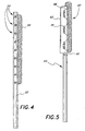
- Figure 4 illustrates an alternative embodiment of the present invention in which an annuloplasty repair segment 50 is removably attached to an elongate, preferably straight holder 52.
- the combined ring 50 and holder 52 are sized to be advanced into implantation position through a minimally invasive access tube or catheter, with a distal portion of the holder 52 remaining straight so that the annuloplasty repair segment 50 also remains straight.
- the straight ring 50 may be attached to a short section of annulus that has been plicated or otherwise tightened where the need to repair the entire annulus is absent.
- the holder 52 need not be flexible, the advantage being the reduced profile or cross-sectional size of the holder and repair segment combination that enables minimally-invasive passage through a tube such as a cannula or catheter.
- the maximum cross-sectional dimension of the holder and repair segment combination is sufficiently small, for example 5-10 mm, so as to pass through known minimally invasive cannulas or catheters.
- the material of the holder 52 may be such that it changes shape and forms a curve upon reaching body temperature. That is, certain shape memory metals (e.g., Nitinol) may be used that undergo a shape change upon crystalline transformation between two temperatures.
- shape memory metals e.g., Nitinol
- markers 54 are also provided on the distal portion of the template 52 to indicate suture placement.
- markers 54 may be, for example, colored or contrasting lines or dots, or may be radiopaque or otherwise highly visible, such as fluorescent. Location and spacing of the individual markers 54 may correspond to particular anatomical landmarks, as previously measured using an endoscope, for example.
- FIG. 5 illustrates a still further embodiment of the present invention in which an annuloplasty repair segment 60 is fastened to a flexible template 62 connected to the distal end of the insertion handle 64 at a hinge 66.
- the ring 60 attaches to the flexible template 62 using one or more mounting sutures 68.
- the mounting suture(s) 68 desirably pass through the suture-permeable ring 60, or may be looped therearound, and are threaded through apertures or guides provided in the template 62 and secure thereto, such as with knots.
- a plurality of cutting guides or prompts 70 are also provided at spaced intervals on the flexible template 62 across which the mounting sutures 68 extend.
- the cutting prompts 70 may take the form of a pair of raised notches across which a suture 68 extends such that a scalpel blade may be inserted between the notches to sever the suture. Examples of such cutting prompts 70 are seen in USPN 5,683,402.
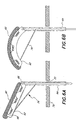
- FIGS 6A and 6B schematically illustrate several steps in implantation of the annuloplasty repair segment 60 and operation of the template 62.
- the assembly of the ring 60, template 62, and handle 64 is first inserted through an access incision 72 in the wall of the chest (schematically shown at 74).
- the flexible template 62 pivots with respect to the handle 64 at the hinge 66.
- Such pivoting may be accomplished using a push or pull mechanism, such as a suture 76 connected at the extreme distal most tip of the template 62 and passing through a series of guides or pulleys (not shown) within the handle 64.
- the hinge 66 permits the flexible template 62 to pivot an angle of less than 90° with respect to the handle 64, after which point further pulling on the suture 76 causes the template 62 to bend, as seen in Figure 6B.
- hinge 66 may permit the template 62 to pivot an angle of between about 70-85°, more preferably about 80°. In this manner, stress imposed on a flexible template 62 is reduced in contrast to simply bending the template through the entire angular rotation.
- Figures 7A-7C illustrate a still further embodiment of present invention in which an annuloplasty repair segment 80 is secured to a multi-segmented template 82 provided on the distal end of a handle 84.
- the template 82 comprises a series of segments 86 linked together at pivot points 88.
- the segmented template 82 can form the curvature seen Figures 7B, but is structurally prevented from curling in the opposite direction.
- FIG. 7C An exemplary cross-section of a segment 86 is seen in Figure 7C and comprises a generally rectilinear shape having a groove or depression 92 on one end for receiving the annuloplasty repair segment 80, and a through bore 94.
- the through bores 94 in each of the segments 86 are aligned to receive a pre-biased bend wire 96.
- Figure 7A is an exploded view, while Figure 7B shows the components assembled with the bend wire 96 causing the segmented template 82 to form the aforementioned curvilinear shape.
- the annuloplasty repair segment 80 conforms to the shape of the bend wire 96 and template 82.
- the assembled components may be advanced through a minimally invasive introducer tube, such as a cannula or a catheter.
- a minimally invasive introducer tube such as a cannula or a catheter.
- the assembly seen in Figure 7B may be partially or completely straight. Further advancement of the assembly from the open distal end of the introducer tube permits the bend wire 96 to curl the template 82 and annuloplasty repair segment 80 into the configuration shown. This technique is much like that shown in Figures 3A-3C for the first two embodiment illustrated.
- the assembly minus the bend wire 96 may be advanced into proximity with the damaged annulus through an access incision, or through a minimally invasive introducer tube. Subsequently, and after projection of the annuloplasty repair segment 80 from the introducer tube, if used, the bend wire 96 may be introduced into the proximal end of the handle 84, as indicated by the arrow 98 in Figure 7B. As the bend wire 96 advances through the aligned through bores 94, the resulting curvilinear shape as seen in Figure 7B is attained.
- Figures 8A-8C illustrate a further holder 100 of the present invention having an annuloplasty repair segment 102 attached to a distal template 104 that is biased to curl in three-dimensions with respect to a proximal handle 106.
- the annuloplasty repair segment 102 may be attached to one side of the template 104, as in the earlier embodiments, or the template may be sized to insert within the repair segment. In the latter instance, the template 102 may be a wire that fits within a receiving bore of the annuloplasty repair segment 102, or the wire may simply slide between an outer fabric cover and inner structure of the repair segment 102.
- the holder 100 may be disposed within and ejected from a delivery tube, such as with the earlier embodiment seen in Figures 3A-3B.
- the pre-biased template 104 assumes its particular three-dimensional shape, and so does the attached annuloplasty repair segment 102.
- the shape of the template 104 re-orients the annuloplasty repair segment 102 from being aligned with the tube axis, to defining a ring or ring segment that lies in a plane angled with respect to the tube axis.
- the ring or ring segment desirably lies in a plane that is nearly perpendicular to the tube axis, which is typical as the native valve annulus lies at a similar orientation with respect to the direction of insertion of the delivery tube.
- the surgeon then attaches the segment 102 in a manner to correct the affected valve annulus, and disconnect the template 104. If the template 104 is attached via sutures, it is disconnected with a scalpel. If the template 104 is inserted within the body of the segment 102, the surgeon braces the segment with forceps, or otherwise, and retracts the template from within.
- the template may be made of a suitable metal or polymer. A lubricious polymer, such as silicon, may be desirable if the template inserts within the segment 102 to facilitate removal therefrom.
- FIGS 9A-9B, 10 and 11 illustrate an annuloplasty delivery system 120 of the present invention having an annuloplasty repair segment 122 attached to a template 124 that is biased to curl when ejected from a proximal delivery sheath 126.
- the template 124 includes a proximal handle section 128 and a distal forming section 130.
- the forming section attaches to or inserts within the annuloplasty repair segment 122, and causes the segment to assume the same shape.
- the handle section 128 is enlarged relative to the forming section 130 and includes a plurality of through holes 132 to which a tether 134 attaches.
- the tether 134 initially coils around and attaches to a post 136 provided on an anchor mandrel 138.
- the anchor mandrel 138 is sized to fit and slide within a delivery tube 140 concentrically disposed within the delivery sheath 126.
- the anchor mandrel 138 further includes a rectangular pin 142 on its distal end that mates with a similarly-sized cavity 144 in the proximal end of the handle section 128 of the template 124.
- the template 124 mates with the anchor mandrel 138, and the two parts as well as the annuloplasty repair segment 122 are housed within the delivery tube 140.
- the delivery tube 140 is initially retracted within the delivery sheath 126 that is typically rigid and inserted though a chest incision or so-called stab wound.
- the delivery sheath 126 may take the form of an elongated, flexible catheter for percutaneous, vascular insertion.
- the delivery tube 140 is advanced from within the delivery sheath, as seen in Figures 9A and 9B.
- the anchor mandrel 138 is at least partially advanced out of the end of the delivery tube 140.
- the anchor mandrel 138 may include an enlarged cylindrical proximal end that is stopped at the end of the delivery tube 140 by a flange or tab.
- At least the post 136 extends from the tube 140, as shown.
- the rectangular pin 142 and cavity 144 may engage with an interference fit, or a more positive coupling may be provided. In either case, the surgeon disengages the two elements to release the template 124.
- the tether 134 maintains a connection between the anchor mandrel 138 and template 124, and thus between the sheath 126 and template.
- the surgeon can maneuver the curled annuloplasty repair segment 122 into the proper position, and attach it to correct the affected annulus.
- the template 124 may be detached from the annuloplasty repair segment 122 by severing connecting sutures, if the template is attached to the side of the segment.
- the forming portion 130 inserts within the repair segment 122, it may be retracted by bracing the segment and pulling the template 124 free, such as by pulling the tether 134.
- the advantage of such a system as shown in Figures 9-11 is the ability of the surgeon to freely maneuver the annuloplasty repair segment 122 into position, within the constraint of an attached handle. Moreover, the template 124 maintains the proper repair segment shape while the attachment procedure is done.
- the annuloplasty repair segment 122 is typically relatively flexible, and the reinforcement of the forming portion 130 greatly reduces the surgeon's task, especially in the small spaces of minimally-invasive surgeries.
- a semi-circular, planar shape of the forming portion 130 is shown, other shapes such as a three-dimensional shape may be utilized, or the shape may be customized based on patient need.
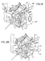
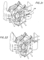
- Figures 12-22 illustrate two exemplary minimally invasive techniques for repairing a heart valve annulus using the present invention.
- Figures 13-16 pertain to an aortic valve repair
- Figures 17-22 pertain to a mitral valve repair.
- These procedures involve creation of an access channel from the outside of the body through the patient's chest cavity, with the heart being stopped and the patient put on bypass. The repair is done with the affected heart valve being exposed through the channel.
- Other procedures are contemplated, however, including a wholly vascular approach with elongated, flexible catheters inserted through the femoral artery, for example, eliminating the chest incision. Therefore, the following methods should be considered exemplary only, and illustrative of the ultimate delivery and implantation of the annuloplasty devices described herein.
- a sternum 150 a planary bone structure centrally disposed in the chest, is connected to a plurality of ribs 152 by respective costal cartilages R1, R2, R3, R4, R5, and L1, L2, L3, L4, L5.
- the heart and great vessels are located within a tissue sack (pericardium), located beneath the sternum, extending laterally under the costal cartilages and ribs, with the aorta disposed in part underlying the second and third right costal cartilages R2 and R3 and a portion of the right coronary artery located generally underlying the vicinity of the fourth and fifth right costal cartilages R4 and R5.
- This procedure can be readily employed to perform operations on structures located on portions of the heart and great vessels located between a point approximately three centimeters above supra annular ridge and the mid-ventricular cavity.
- the procedure is of particular utility with respect to surgery to repair or replace the aortic valve.
- the patient is anesthetized and intubated, and placed supine on the operating room table.
- defibrillator pads are placed on the patient's back and anterior left chest, and a transesophageal echocardiography probe is placed to access the etiology of the aortic valve disease and to assist in removing air from the heart after completion of the operation.
- a right parasternal incision is made extending from the lower edge of the second costal cartilage R2 to the superior edge of the fifth costal cartilage.
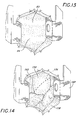
- the pectoral major muscle is divided, exposing the second, third, and fourth intercostal spaces, and the third and fourth costal cartilages R3 and R4 as shown in Figure 13.
- the third and fourth costal cartilages R3 and R4 are totally excised ( Figure 12).
- the right internal thoracic artery is ligated just below the second costal cartilage R2 and just above the fifth costal cartilage R5.
- Intercostal muscles and pleura are incised lateral to the edge of the sternum, entering the right pleural cavity.
- the pericardium 156 is then incised, exposing the ascending aorta 158, and is stitched back.
- the incision is held open using a conventional chest retractor 160.
- a cardiopulmonary by-pass is then established.
- a common femoral artery and vein are exposed and, after infusion of an anti-coagulant, e.g., heparinization, are cannulated.
- Catheters are placed in the femoral artery and in femoral vein, respectively.
- Adequate venous drainage may be obtained by utilizing a long venous cannula disposed so that the tip of the cannula passes through the right atrium and preferably into the superior vena cava 162 ( Figure 14).
- venous return can be affected by introducing an appropriate catheter into the right atrial appendage.
- Catheters direct the blood to a conventional heart-lung machine (not shown) that oxygenates the blood and pumps it back under pressure to the patient.
- the heart is excluded from circulation.
- the aorta 158 is suitably encircled with umbilical tape 170 and the ascending aorta cross clamped with a right angle clamp 172.
- the aorta is then incised along line 174 in Figure 14 to expose the coronary ostia 166 and the aortic valve 178, as seen in Figure 15.
- Aortic valve 178 includes a plurality, typically three, of leaflets (valve cusps) 180, joined at respective commissures 182, and surrounded by a relatively fibrous aortic annulus 184.
- Cardiac function is arrested, by e.g., by administering cardioplegia into the ascending aorta.
- a suitable cardioplegia is introduced into the left coronary artery.
- a suitable cardioplegia fluid such as a coldpotassium solution is infused through a catheter 186 inserted in coronary ostia 176.
- Sutures 188 are the suitably placed just above each commissure 182, and clamped under tension to a drape (not shown) surrounding the operating site. This elevates the aortic root (e.g., aortic annulus 184) into the operative field.
- Aortic valve 178 is then repaired.
- the annuloplasty delivery system 120 of Figures 9-11 is introduced into the surgical field and the annuloplasty repair segment 122 attached to the template 124 is released into proximity of the annulus 184 from the delivery sheath 126.
- the tether 134 maintains a connection between the template 124 and delivery sheath 126 as the repair segment 122 is maneuvered and secured into a corrective position in the annulus 184.
- Various implements are known for manipulating and suturing surgical devices in tight spaces, including robotically-assisted forceps and suture needles or stapling mechanisms, and will not be described or shown here.
- the template 124 is disengaged from the repair segment 122, and the annuloplasty delivery system 120 removed from the surgical site.
- the aortatomy is closed with sutures. Air is then removed from the heart through the aorta with the assistance of the transesophageal echocardiography probe; all air bubbles are preferably removed from the heart by removing clamp 74 to restore blood flow, and inflating the lungs, until blood flows through the closure sutures, then tightening the sutures.
- a similar incision as that described above with reference to Figures 12 and 12A, can be used in performing surgery to repair or replace a mitral valve. More specifically, referring to Figures 12A, a parasternal incision approximately 10cm in length is made over the third and fourth intercostal cartilages R3 and R4. The pectoralis major muscle is then divided longitudinally, exposing the third and fourth cartilages R3, R4. The cartilages R3, R4 are completely resected and the internal thoracic artery (not shown) is then ligated and divided. The pericardium is opened and suspended under tension to the drapes of the patient.
- the resulting wound provides access into the chest cavity and particularly exposes the first portion of the ascending aorta 196, the superior vena cava 198 and the right atrium 200.
- the wound also provides access for making a planned incision 202 into the right atrium 200.
- a first cannula (not shown) is inserted directly into the superior vena cava 198.
- a second cannula may be inserted into the inferior vena cava, either via the right atrium 200 or via a venous cannula introduced through a femoral vein as known in the art.
- Arterial return is established by a third cannula that may be inserted either directly into the ascending aorta 196 or through a femoral artery.
- a cross clamp 204 is applied to the ascending aorta 196 as shown in Figure 18 to occlude blood flow.
- Antegrade cardioplegia is then applied directly into the ascending aorta proximal of the clamp via a cardioplegia catheter 206.
- Bypass is established and then the heart progressively diminishes its beating activity until it ceases beating altogether.
- the incision 202 into the right atrium 200 is made and the tissue draped back to expose the coronary sinus 208 and intra-arterial septum 210 ( Figure 18). Additional cardioplegia is introduced, as necessary, in a retrograde fashion into the coronary sinus 208 with a retrograde cardioplegia catheter 212.
- the retrograde cardioplegia catheter 212 can be either a conventional retrograde catheter or an occluding balloon catheter to ensure proper introduction of the cardioplegia without leakage.
- the stage is then set to cut the intra-atrial septum 210 along an incision line 214 and thereby expose the dome of the left atrium.
- the incision 214 is made in the intra-atrial septum 210 starting at the foramen ovale and extending inferiorly and superiorly into the dome of the left atrium.
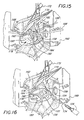
- hand-held refractors 220, 222 are then inserted into the superior and inferior portions of the left atrium, respectively, and used to pull the atrial tissue back and expose the mitral valve 224. Additionally, downward traction may be applied on the posterior lateral left atrial wall 225 to provide better exposure to the mitral valve 224.
- a deformable retractor 226, which may be manipulated into a shape that grasps the tissue but does not obstruct the surgical field, may be used to provide the downward traction on the posterior lateral left atrial wall 224.
- a flexible and resilient ring member 228 may be inserted into the field between the valve 224 and the left atrial wall.
- the ring 228 expands to facilitate lifting the tissue away from the valve area requiring surgery.
- the mitral valve 224 being fully exposed after achieving the above-described configuration, repair of the valve 224 may then be achieved using the devices of the present invention.
- the procedure for completing the surgical method after repair of a mitral valve is hereinafter described.
- annuloplasty is performed.
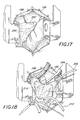
- theannuloplasty delivery system 120 of Figures 9-11 is introduced into the surgical field and the annuloplasty repair segment 122 attached to the template 124 is released into proximity of the annulus 230 from the delivery sheath 126.
- the tether 134 maintains a connection between the template 124 and delivery sheath 126 as the repair segment 122 is maneuvered and secured by sutures 232 into a corrective position in the annulus 230.
- various implements are known for manipulating and suturing surgical devices in tight spaces, including robotically-assisted forceps and suture needles or stapling mechanisms, and will not be described or shown here.
- the template 124 is disengaged from the repair segment 122, and the annuloplasty delivery system 120 removed from the surgical site, as in Figure 22.
- the present invention thus provides an improved annuloplasty delivery system and/or holder that is especially suitable for minimally-invasive surgeries.
- the system enables delivery of an annuloplasty repair segment to the valve annulus through a tube, such as a catheter or cannula
- the system/holder includes a template to which the repair segment attaches that is capable of undergoing a shape change, either actively via a deflection mechanism or passively by virtue of instrinsic properties, such as a spring bias or material memory.
- the shape may be two- or three-dimensions, and typically forms a curve along at least a portion to conform around the annulus.
- the template is desirably an elongate member that assumes a generally linear shape for passing through the delivery tube, and then is actively or passively converted to the changed shape upon exiting from the distal end of the tube.
- the repair segment may be various lengths, from relatively short to almost a complete ring shape, and is flexible to assume the respective shapes of the template.
- the template may remain rigidly attached to a handle that extends from the proximal end of the tube, or may be released to enable free manipulation by the surgeon at the implantation site.
- a tether may be provided to maintain connection between the delivery tube and template while permitting maximum access and visibility around the repair segment during the attachment procedure.
- the template remains attached to the repair segment during the attachment procedure to support and maintain a desired shape of the repair segment. Once the repair segment is implanted, the template is detached, such as by severing connecting sutures, or by pulling it longitudinally from within the repair segment.
Abstract
Description
- The present invention relates generally to medical devices and particularly to a holder for delivering annuloplasty repair segments or rings especially for use in minimally-invasive surgeries.
-
- Figure 1 is an elevational view of a holder of the present invention having an annuloplasty repair segment attached to a flexible distal template;
- Figure 2 is an elevational view of an alternative holder of the present invention having an annuloplasty repair segment attached to a flexible distal template;
- Figure 3A-D are elevational views of the deployment of the holder of Figure 1 from within a delivery tube;
- Figure 4 is an elevational view of a still further holder of the present invention having an annuloplasty repair segment attached to a distal template having markers;
- Figure 5 is an elevational view of another holder of the present invention having an annuloplasty repair segment attached to a flexible distal template that can pivot with respect to a proximal handle;
- Figure 6A and 6B are elevational views of the deployment of the holder of Figure 5;
- Figures 7A and 7B are elevational views of another holder of the present invention having an annuloplasty repair segment attached to a distal multi-segmented template that can curl with respect to a proximal handle upon actuation of a pull string;
- Figures 8A-8C are perspective views of a further holder of the present invention having an annuloplasty repair segment attached to a distal template that is biased to curl in three-dimensions with respect to a proximal handle;
- Figures 9A and 9B are perspective views of an annuloplasty delivery system of the present invention having an annuloplasty repair segment attached to a template that is biased to curl when ejected from a proximal delivery tube;
- Figure 14 is a perspective exploded view of the annuloplasty delivery system of Figures 9A and 9B;
- Figure 11 is an enlarged perspective view of the distal end of the annuloplasty delivery system of Figures 9A and 9B;
- Figures 12 and 12A are schematic illustrations depicting a human chest and the disposition of a right parasternal incision in connection with an aortic surgery procedure in accordance with the present invention;
- Figure 13 is a pictorial illustration depicting the right parasternal incision of Figure 12 showing respective costal cartilages;
- Figure 14 is a pictorial illustration depicting the right parasternal incision of Figure 12 after respective costal cartilage units are excised and incision retracted;
- Figure 15 is a pictorial illustration depicting the right parasternal incision of Figure 12 after the aortic valve is removed, with traction sutures placed at the commissures;
- Figure 16 is a pictorial illustration depicting the right parasternal incision of Figure 12 after the aorta is opened to expose the aortic valve, and injection of cardioplegia into the coronary ostia;
- Figure 17 is a pictorial illustration of the implantation of an annuloplasty ring of the present invention to repair the aortic valve;
- Figure 18 is a pictorial illustration depicting the surgery field of Figure 17 after an incision of the right atrium;
- Figure 19 is a pictorial illustration depicting an alternative way of exposing the surgical field of Figure 17;
- Figure 20 is a pictorial illustration of the performance of an annuloplasty in the surgical field of Figure 17;
- Figure 21 is a pictorial illustration of the performance of an annuloplasty in the surgical field of Figure 17; and
- Figure 22 is a pictorial illustration of the completion of an annuloplasty in the surgical field of Figure 17.
- The present invention provides a number of different holders in accordance with claim 1 for delivering and facilitating implantation of annuloplasty rings or repair segments. According to independent claim 13, the holder is combined with an annuloplasty repair segment.
Independent claim 26 refers to an annuloplasty repair segment delivery system. It should be understood that the term annuloplasty ring or repair segments refers to any generally elongated structure used in annulus repair, whether straight or curved. For example, an annuloplasty ring is conventionally understood to provide either a complete or substantially complete loop sized to correct a misshapen and or dilated native annulus. In many instances, a partial ring or even a straight repair segment may be used around just a portion of the annulus, such as around the posterior edge. Consequently, the term "annuloplasty repair segment" as used herein is intended to encompass all of such structures. Additionally, although annuloplasty repair devices are typically suture-permeable, the use of the invention to implant other structures which are attached to the annulus without passage of sutures therethrough is also contemplated. - A first embodiment of the present invention is illustrated in Figure 1 in which an
annuloplasty repair segment 20 is attached to acurved template portion 22 of adelivery holder 24. Theannuloplasty repair segment 20 is flexible and conforms to thecurved portion 22 by virtue of a plurality of attachingsutures 26, or other similar expedient. - The
holder 24 comprises thecurved portion 22 defining a distal end, and a generally straight,elongated shaft portion 28 defining a proximal end. Depending on the implantation technique, theshaft 28 may be flexible or rigid. Thecurved portion 22, on the other hand, is highly flexible, preferably elastic. Specifically,curved portion 22 may be formed of a biocompatible metal such as stainless-steel or Elgiloy, or from a super-elastic material such as Nitinol. The material used for thecurved portion 22 may be the same as that used for theshaft portion 28, or the two portions may be formed of different material and connected using conventional means. The usage of theholder 24 will be described below with respect to Figures 3A-3C. - Figure 2 illustrates an alternative embodiment of the present invention similar to that shown in Figure 1, with an
annuloplasty repair segment 20 supported on a curved wire-like template portion 30 of aholder 32. Again, theholder 32 comprises the wire-like template portion 30 on the distal end, and ashaft portion 34 on the proximal end. - In contrast to the suture attachment means shown in Figure 1, the curved wire-
like portion 30 passes through the body of theannuloplasty repair segment 20 to secure it thereto. In this regard, therefore, theannuloplasty repair segment 20 must be sufficiently permeable for the wire-like portion 30 to pass therethrough. In one embodiment, theannuloplasty repair segment 20 comprises an elastic inner core (not shown) surrounded by a tubular fabric covering 36. The wire-like portion 30 may therefore be passed between the inner core and the fabric covering 36, or may even be embedded within the inner core for a more secure coupling. The inner core may take a number of forms, including a solid metal rod such as titanium, a metal rod in combination with a silicone sleeve, or a silicone rod. Various other annuloplasty repair segment constructions are well-known in the art, and are incorporated herein. - Figures 3A-3C illustrate a series of positions of the combined
annuloplasty repair segment 20 andholder 24 of Figure 1 being delivered through adelivery tube 40, such as a cannula or catheter. It should be understood that the same operation applies to the combinedring 20 andholder 34 shown in Figure 2. - The
delivery tube 40 comprises a proximal end (not shown) and an opendistal end 42. In use, the combinedannuloplasty repair segment 20 andholder 24 are located as shown adjacent thedistal end 42, or are advanced into that positioned through thetube 40. It should be noted that thecurved template portion 22 on the distal end of the holder 24 (and the attached ring 20) assumes a straightened or elongate configuration when located within thetube 40. - As will be explained in greater detail below, the
distal end 42 is advanced into proximity with the site at which theannuloplasty repair segment 20 will be implanted; namely, a distended or otherwise damaged heart valve annulus. Subsequently, as seen Figures 3B-3D, the combinedannuloplasty repair segment 20 andholder 24 are advanced from thedistal end 42 in the direction ofarrow 44. By virtue of the elasticity of thecurved portion 22, theannuloplasty repair segment 20 ultimately undergoes a shape change to the curved shape as seen in Figure 3D. As thecurved portion 22 passes from thedistal end 42 of thetube 40, its own spring-bias causes it to revert to its original shape. It should be noted that the spring bias might be in more than one plane. That is, the resulting curved configuration may be a three-dimensional shape as desired. - The
holder 24 may be advanced from theopen mouth 42 by either distal displacement of theholder 24 with respect to thefixed tube 40, or by proximal displacement of thetube 40 with respect to thefixed holder 24. That is, theholder 24 can be pushed from within thetube 40, or the tube can be retracted to expose thering 20 andcurved portion 22. In an exemplary embodiment, theshaft 28 extends a sufficient distance in the proximal direction to emerge from within the proximal end (not shown) of thetube 40, and is manipulated by a handle, or other such means. - Figure 4 illustrates an alternative embodiment of the present invention in which an
annuloplasty repair segment 50 is removably attached to an elongate, preferablystraight holder 52. In this embodiment, the combinedring 50 andholder 52 are sized to be advanced into implantation position through a minimally invasive access tube or catheter, with a distal portion of theholder 52 remaining straight so that theannuloplasty repair segment 50 also remains straight. Thestraight ring 50 may be attached to a short section of annulus that has been plicated or otherwise tightened where the need to repair the entire annulus is absent. In this regard, theholder 52 need not be flexible, the advantage being the reduced profile or cross-sectional size of the holder and repair segment combination that enables minimally-invasive passage through a tube such as a cannula or catheter. In a preferred embodiment, the maximum cross-sectional dimension of the holder and repair segment combination is sufficiently small, for example 5-10 mm, so as to pass through known minimally invasive cannulas or catheters. - Alternatively, the material of the
holder 52 may be such that it changes shape and forms a curve upon reaching body temperature. That is, certain shape memory metals (e.g., Nitinol) may be used that undergo a shape change upon crystalline transformation between two temperatures. - A plurality of
markers 54 are also provided on the distal portion of thetemplate 52 to indicate suture placement.Such markers 54 may be, for example, colored or contrasting lines or dots, or may be radiopaque or otherwise highly visible, such as fluorescent. Location and spacing of theindividual markers 54 may correspond to particular anatomical landmarks, as previously measured using an endoscope, for example. - Figure 5 illustrates a still further embodiment of the present invention in which an
annuloplasty repair segment 60 is fastened to aflexible template 62 connected to the distal end of the insertion handle 64 at ahinge 66. Thering 60. attaches to theflexible template 62 using one or more mounting sutures 68. The mounting suture(s) 68 desirably pass through the suture-permeable ring 60, or may be looped therearound, and are threaded through apertures or guides provided in thetemplate 62 and secure thereto, such as with knots. A plurality of cutting guides or prompts 70 are also provided at spaced intervals on theflexible template 62 across which the mountingsutures 68 extend. The cutting prompts 70 may take the form of a pair of raised notches across which asuture 68 extends such that a scalpel blade may be inserted between the notches to sever the suture. Examples of such cutting prompts 70 are seen in USPN 5,683,402. - Figures 6A and 6B schematically illustrate several steps in implantation of the
annuloplasty repair segment 60 and operation of thetemplate 62. The assembly of thering 60,template 62, and handle 64 is first inserted through anaccess incision 72 in the wall of the chest (schematically shown at 74). After locating theannuloplasty repair segment 60 in proximity with the damaged annulus, theflexible template 62 pivots with respect to thehandle 64 at thehinge 66. Such pivoting may be accomplished using a push or pull mechanism, such as asuture 76 connected at the extreme distal most tip of thetemplate 62 and passing through a series of guides or pulleys (not shown) within thehandle 64. In a preferred embodiment, thehinge 66 permits theflexible template 62 to pivot an angle of less than 90° with respect to thehandle 64, after which point further pulling on thesuture 76 causes thetemplate 62 to bend, as seen in Figure 6B. For example, hinge 66 may permit thetemplate 62 to pivot an angle of between about 70-85°, more preferably about 80°. In this manner, stress imposed on aflexible template 62 is reduced in contrast to simply bending the template through the entire angular rotation. - Figures 7A-7C illustrate a still further embodiment of present invention in which an
annuloplasty repair segment 80 is secured to amulti-segmented template 82 provided on the distal end of ahandle 84. Thetemplate 82 comprises a series ofsegments 86 linked together at pivot points 88. By forming thesegments 86 withcutouts 90, for example, thesegmented template 82 can form the curvature seen Figures 7B, but is structurally prevented from curling in the opposite direction. - An exemplary cross-section of a
segment 86 is seen in Figure 7C and comprises a generally rectilinear shape having a groove ordepression 92 on one end for receiving theannuloplasty repair segment 80, and a throughbore 94. The through bores 94 in each of thesegments 86 are aligned to receive apre-biased bend wire 96. Figure 7A is an exploded view, while Figure 7B shows the components assembled with thebend wire 96 causing thesegmented template 82 to form the aforementioned curvilinear shape. In addition, theannuloplasty repair segment 80 conforms to the shape of thebend wire 96 andtemplate 82. - In use, the assembled components, including the
bend wire 96, may be advanced through a minimally invasive introducer tube, such as a cannula or a catheter. Depending on the rigidity of the introducer tube, the assembly seen in Figure 7B may be partially or completely straight. Further advancement of the assembly from the open distal end of the introducer tube permits thebend wire 96 to curl thetemplate 82 andannuloplasty repair segment 80 into the configuration shown. This technique is much like that shown in Figures 3A-3C for the first two embodiment illustrated. - Alternatively, the assembly minus the
bend wire 96 may be advanced into proximity with the damaged annulus through an access incision, or through a minimally invasive introducer tube. Subsequently, and after projection of theannuloplasty repair segment 80 from the introducer tube, if used, thebend wire 96 may be introduced into the proximal end of thehandle 84, as indicated by thearrow 98 in Figure 7B. As thebend wire 96 advances through the aligned throughbores 94, the resulting curvilinear shape as seen in Figure 7B is attained. - Figures 8A-8C illustrate a
further holder 100 of the present invention having anannuloplasty repair segment 102 attached to adistal template 104 that is biased to curl in three-dimensions with respect to aproximal handle 106. Theannuloplasty repair segment 102 may be attached to one side of thetemplate 104, as in the earlier embodiments, or the template may be sized to insert within the repair segment. In the latter instance, thetemplate 102 may be a wire that fits within a receiving bore of theannuloplasty repair segment 102, or the wire may simply slide between an outer fabric cover and inner structure of therepair segment 102. - In use, the
holder 100 may be disposed within and ejected from a delivery tube, such as with the earlier embodiment seen in Figures 3A-3B. Once the distal end of theholder 100 emerges from within the tube, thepre-biased template 104 assumes its particular three-dimensional shape, and so does the attachedannuloplasty repair segment 102. Ideally, the shape of thetemplate 104 re-orients theannuloplasty repair segment 102 from being aligned with the tube axis, to defining a ring or ring segment that lies in a plane angled with respect to the tube axis. As best seen in Figure 8A, the ring or ring segment desirably lies in a plane that is nearly perpendicular to the tube axis, which is typical as the native valve annulus lies at a similar orientation with respect to the direction of insertion of the delivery tube. The surgeon then attaches thesegment 102 in a manner to correct the affected valve annulus, and disconnect thetemplate 104. If thetemplate 104 is attached via sutures, it is disconnected with a scalpel. If thetemplate 104 is inserted within the body of thesegment 102, the surgeon braces the segment with forceps, or otherwise, and retracts the template from within. The template may be made of a suitable metal or polymer. A lubricious polymer, such as silicon, may be desirable if the template inserts within thesegment 102 to facilitate removal therefrom. - Figures 9A-9B, 10 and 11 illustrate an
annuloplasty delivery system 120 of the present invention having anannuloplasty repair segment 122 attached to atemplate 124 that is biased to curl when ejected from aproximal delivery sheath 126. Thetemplate 124 includes aproximal handle section 128 and a distal formingsection 130. The forming section attaches to or inserts within theannuloplasty repair segment 122, and causes the segment to assume the same shape. Thehandle section 128 is enlarged relative to the formingsection 130 and includes a plurality of through holes 132 to which atether 134 attaches. Thetether 134, in turn, initially coils around and attaches to apost 136 provided on ananchor mandrel 138. Theanchor mandrel 138 is sized to fit and slide within adelivery tube 140 concentrically disposed within thedelivery sheath 126. Theanchor mandrel 138 further includes arectangular pin 142 on its distal end that mates with a similarly-sized cavity 144 in the proximal end of thehandle section 128 of thetemplate 124. - In use, the
template 124 mates with theanchor mandrel 138, and the two parts as well as theannuloplasty repair segment 122 are housed within thedelivery tube 140. Thedelivery tube 140 is initially retracted within thedelivery sheath 126 that is typically rigid and inserted though a chest incision or so-called stab wound. As before, however, thedelivery sheath 126 may take the form of an elongated, flexible catheter for percutaneous, vascular insertion. - After the distal end of the
delivery sheath 126 is positioned near the valve annulus site, thedelivery tube 140 is advanced from within the delivery sheath, as seen in Figures 9A and 9B. Using a pusher rod (not shown), theanchor mandrel 138 is at least partially advanced out of the end of thedelivery tube 140. Theanchor mandrel 138 may include an enlarged cylindrical proximal end that is stopped at the end of thedelivery tube 140 by a flange or tab. At least thepost 136 extends from thetube 140, as shown. Therectangular pin 142 andcavity 144 may engage with an interference fit, or a more positive coupling may be provided. In either case, the surgeon disengages the two elements to release thetemplate 124. Thetether 134 maintains a connection between theanchor mandrel 138 andtemplate 124, and thus between thesheath 126 and template. - By manipulating the
handle portion 128, the surgeon can maneuver the curledannuloplasty repair segment 122 into the proper position, and attach it to correct the affected annulus. At this stage, thetemplate 124 may be detached from theannuloplasty repair segment 122 by severing connecting sutures, if the template is attached to the side of the segment. Alternatively, if the formingportion 130 inserts within therepair segment 122, it may be retracted by bracing the segment and pulling thetemplate 124 free, such as by pulling thetether 134. - The advantage of such a system as shown in Figures 9-11 is the ability of the surgeon to freely maneuver the
annuloplasty repair segment 122 into position, within the constraint of an attached handle. Moreover, thetemplate 124 maintains the proper repair segment shape while the attachment procedure is done. Theannuloplasty repair segment 122 is typically relatively flexible, and the reinforcement of the formingportion 130 greatly reduces the surgeon's task, especially in the small spaces of minimally-invasive surgeries. Finally, although a semi-circular, planar shape of the formingportion 130 is shown, other shapes such as a three-dimensional shape may be utilized, or the shape may be customized based on patient need. - Figures 12-22 illustrate two exemplary minimally invasive techniques for repairing a heart valve annulus using the present invention. Figures 13-16 pertain to an aortic valve repair, while Figures 17-22 pertain to a mitral valve repair. These procedures involve creation of an access channel from the outside of the body through the patient's chest cavity, with the heart being stopped and the patient put on bypass. The repair is done with the affected heart valve being exposed through the channel. Other procedures are contemplated, however, including a wholly vascular approach with elongated, flexible catheters inserted through the femoral artery, for example, eliminating the chest incision. Therefore, the following methods should be considered exemplary only, and illustrative of the ultimate delivery and implantation of the annuloplasty devices described herein.
- Referring now to Figure 12, in a typical human, a
sternum 150, a planary bone structure centrally disposed in the chest, is connected to a plurality ofribs 152 by respective costal cartilages R1, R2, R3, R4, R5, and L1, L2, L3, L4, L5. The heart and great vessels are located within a tissue sack (pericardium), located beneath the sternum, extending laterally under the costal cartilages and ribs, with the aorta disposed in part underlying the second and third right costal cartilages R2 and R3 and a portion of the right coronary artery located generally underlying the vicinity of the fourth and fifth right costal cartilages R4 and R5. - It has been determined that a surgery on portions of the heart and great vessels located between a point approximately three centimeters above supra annular ridge and the mid-ventricular cavity, can be effected with minimal invasion, without a median sternotomy, or other gross thoracotomy, by, as illustrated in Figure 12, making a relatively short
parasternal incision 154 extending across a predetermined number of costal cartilage, e.g., a right parasternal incision extending from the lower edge of the second costal cartilage R2 to the superior edge of the fifth costal cartilage R5 and removing one or more costal cartilages, e.g., the third and fourth costal cartilages, R3 and R4. It has been determined that over a period of time the chest wall in the area of the resected cartilages becomes stable secondary to scarring of the remaining tissue. In effect, scar tissue resulting from the procedure functionally replaces the excised cartilage, providing a relatively rigid chest wall. - This procedure can be readily employed to perform operations on structures located on portions of the heart and great vessels located between a point approximately three centimeters above supra annular ridge and the mid-ventricular cavity. As will be more fully described, the procedure is of particular utility with respect to surgery to repair or replace the aortic valve. Specifically, in the context of exemplary surgery to replace an aortic valve, the patient is anesthetized and intubated, and placed supine on the operating room table. Preferably, defibrillator pads are placed on the patient's back and anterior left chest, and a transesophageal echocardiography probe is placed to access the etiology of the aortic valve disease and to assist in removing air from the heart after completion of the operation.
- Referring to Figures 12 and 12A, a right parasternal incision is made extending from the lower edge of the second costal cartilage R2 to the superior edge of the fifth costal cartilage. The pectoral major muscle is divided, exposing the second, third, and fourth intercostal spaces, and the third and fourth costal cartilages R3 and R4 as shown in Figure 13. The third and fourth costal cartilages R3 and R4 are totally excised (Figure 12). The right internal thoracic artery is ligated just below the second costal cartilage R2 and just above the fifth costal cartilage R5. Intercostal muscles and pleura are incised lateral to the edge of the sternum, entering the right pleural cavity. As shown in Figure 14, the
pericardium 156 is then incised, exposing the ascendingaorta 158, and is stitched back. The incision is held open using aconventional chest retractor 160. - A cardiopulmonary by-pass is then established. Typically, a common femoral artery and vein are exposed and, after infusion of an anti-coagulant, e.g., heparinization, are cannulated. Catheters are placed in the femoral artery and in femoral vein, respectively. Adequate venous drainage may be obtained by utilizing a long venous cannula disposed so that the tip of the cannula passes through the right atrium and preferably into the superior vena cava 162 (Figure 14). Alternatively, venous return can be affected by introducing an appropriate catheter into the right atrial appendage. Catheters direct the blood to a conventional heart-lung machine (not shown) that oxygenates the blood and pumps it back under pressure to the patient.
- After catheters are placed, the heart is excluded from circulation. For example, the
aorta 158 is suitably encircled withumbilical tape 170 and the ascending aorta cross clamped with aright angle clamp 172. The aorta is then incised alongline 174 in Figure 14 to expose the coronary ostia 166 and theaortic valve 178, as seen in Figure 15.Aortic valve 178 includes a plurality, typically three, of leaflets (valve cusps) 180, joined atrespective commissures 182, and surrounded by a relatively fibrousaortic annulus 184. Cardiac function is arrested, by e.g., by administering cardioplegia into the ascending aorta. Typically, after performing the aortatomy, a suitable cardioplegia is introduced into the left coronary artery. Preferably, a suitable cardioplegia fluid, such as a coldpotassium solution is infused through acatheter 186 inserted incoronary ostia 176.Sutures 188 are the suitably placed just above eachcommissure 182, and clamped under tension to a drape (not shown) surrounding the operating site. This elevates the aortic root (e.g., aortic annulus 184) into the operative field. -
Aortic valve 178 is then repaired. For example, referring to Figure 16, theannuloplasty delivery system 120 of Figures 9-11 is introduced into the surgical field and theannuloplasty repair segment 122 attached to thetemplate 124 is released into proximity of theannulus 184 from thedelivery sheath 126. Thetether 134 maintains a connection between thetemplate 124 anddelivery sheath 126 as therepair segment 122 is maneuvered and secured into a corrective position in theannulus 184. Various implements are known for manipulating and suturing surgical devices in tight spaces, including robotically-assisted forceps and suture needles or stapling mechanisms, and will not be described or shown here. Finally, thetemplate 124 is disengaged from therepair segment 122, and theannuloplasty delivery system 120 removed from the surgical site. - At the completion of the repair, the aortatomy is closed with sutures. Air is then removed from the heart through the aorta with the assistance of the transesophageal echocardiography probe; all air bubbles are preferably removed from the heart by removing
clamp 74 to restore blood flow, and inflating the lungs, until blood flows through the closure sutures, then tightening the sutures. - A similar incision as that described above with reference to Figures 12 and 12A, can be used in performing surgery to repair or replace a mitral valve. More specifically, referring to Figures 12A, a parasternal incision approximately 10cm in length is made over the third and fourth intercostal cartilages R3 and R4. The pectoralis major muscle is then divided longitudinally, exposing the third and fourth cartilages R3, R4. The cartilages R3, R4 are completely resected and the internal thoracic artery (not shown) is then ligated and divided. The pericardium is opened and suspended under tension to the drapes of the patient.
- Referring to Figure 17, the resulting wound provides access into the chest cavity and particularly exposes the first portion of the ascending
aorta 196, thesuperior vena cava 198 and theright atrium 200. The wound also provides access for making aplanned incision 202 into theright atrium 200. - Referring to Figure 18, prior to making the
incision 202 into theright atrium 200, the patient must be cannulated so that the heart may be bypassed from blood flow during the surgery on the heart. In that connection, a first cannula (not shown) is inserted directly into thesuperior vena cava 198. A second cannula may be inserted into the inferior vena cava, either via theright atrium 200 or via a venous cannula introduced through a femoral vein as known in the art. Arterial return is established by a third cannula that may be inserted either directly into the ascendingaorta 196 or through a femoral artery. - Once cannulation is complete, a
cross clamp 204 is applied to the ascendingaorta 196 as shown in Figure 18 to occlude blood flow. Antegrade cardioplegia is then applied directly into the ascending aorta proximal of the clamp via acardioplegia catheter 206. Bypass is established and then the heart progressively diminishes its beating activity until it ceases beating altogether. Theincision 202 into theright atrium 200 is made and the tissue draped back to expose thecoronary sinus 208 and intra-arterial septum 210 (Figure 18). Additional cardioplegia is introduced, as necessary, in a retrograde fashion into thecoronary sinus 208 with aretrograde cardioplegia catheter 212. Theretrograde cardioplegia catheter 212 can be either a conventional retrograde catheter or an occluding balloon catheter to ensure proper introduction of the cardioplegia without leakage. The stage is then set to cut theintra-atrial septum 210 along anincision line 214 and thereby expose the dome of the left atrium. Theincision 214 is made in theintra-atrial septum 210 starting at the foramen ovale and extending inferiorly and superiorly into the dome of the left atrium. - With reference to Figure 19, hand-held
refractors mitral valve 224. Additionally, downward traction may be applied on the posterior lateral leftatrial wall 225 to provide better exposure to themitral valve 224. Adeformable retractor 226, which may be manipulated into a shape that grasps the tissue but does not obstruct the surgical field, may be used to provide the downward traction on the posterior lateral leftatrial wall 224. In addition, to further expose the surgical field, a flexible andresilient ring member 228 may be inserted into the field between thevalve 224 and the left atrial wall. After the ring member is inserted, thering 228 expands to facilitate lifting the tissue away from the valve area requiring surgery. Themitral valve 224 being fully exposed after achieving the above-described configuration, repair of thevalve 224 may then be achieved using the devices of the present invention. By way of example only, the procedure for completing the surgical method after repair of a mitral valve is hereinafter described. - Referring to Figures 20-22, after exposure of the
mitral valve 224, an annuloplasty is performed. For example,theannuloplasty delivery system 120 of Figures 9-11 is introduced into the surgical field and theannuloplasty repair segment 122 attached to thetemplate 124 is released into proximity of theannulus 230 from thedelivery sheath 126. Thetether 134 maintains a connection between thetemplate 124 anddelivery sheath 126 as therepair segment 122 is maneuvered and secured bysutures 232 into a corrective position in theannulus 230. Again, various implements are known for manipulating and suturing surgical devices in tight spaces, including robotically-assisted forceps and suture needles or stapling mechanisms, and will not be described or shown here. Finally, thetemplate 124 is disengaged from therepair segment 122, and theannuloplasty delivery system 120 removed from the surgical site, as in Figure 22. - The present invention thus provides an improved annuloplasty delivery system and/or holder that is especially suitable for minimally-invasive surgeries. The system enables delivery of an annuloplasty repair segment to the valve annulus through a tube, such as a catheter or cannulaThe system/holder includes a template to which the repair segment attaches that is capable of undergoing a shape change, either actively via a deflection mechanism or passively by virtue of instrinsic properties, such as a spring bias or material memory. The shape may be two- or three-dimensions, and typically forms a curve along at least a portion to conform around the annulus. The template is desirably an elongate member that assumes a generally linear shape for passing through the delivery tube, and then is actively or passively converted to the changed shape upon exiting from the distal end of the tube. The repair segment may be various lengths, from relatively short to almost a complete ring shape, and is flexible to assume the respective shapes of the template. The template may remain rigidly attached to a handle that extends from the proximal end of the tube, or may be released to enable free manipulation by the surgeon at the implantation site. A tether may be provided to maintain connection between the delivery tube and template while permitting maximum access and visibility around the repair segment during the attachment procedure. The template remains attached to the repair segment during the attachment procedure to support and maintain a desired shape of the repair segment. Once the repair segment is implanted, the template is detached, such as by severing connecting sutures, or by pulling it longitudinally from within the repair segment.
- While the foregoing is a complete description of the preferred embodiments of the invention, various alternatives, modifications, and equivalents may be used. Moreover, it will be obvious that certain other modifications may be practiced within the scope of the appended claims.
Claims (32)
- A holder (24) for an annuloplasty repair segment, the holder comprising:a distal portion in the form of an elongate template (22) adapted to attach to an annuloplasty repair segment and being adapted to pass in a generally linear shape through a tube, the template being convertible from the generally linear shape to a curved shape and a proximal portion in the form of generally straight elongate shaft portion (28).
- The holder of claim 1, wherein the template (22) is flexible.
- The holder of claim 2, wherein the template (22) is biased toward the curved shape.
- The holder of claim 1, wherein the curved shape is three-dimensional.
- The holder of claim 1, further including a deflection mechanism for converting the template between the linear shape and the curved shape.
- The holder of claim 1, wherein the template is capable of a temperature-induced shape change between the linear shape and the curved shape.
- The holder of claim 1, wherein the template includes a plurality of hinged sections (86).
- The holder of claim 7, further including a deflection mechanism for converting the template between the linear shape and the curved shape.
- The holder of claim 1, wherein the template is flexible but unbiased from the linear shape, the holder further including a biasing member (96) adapted to insert within the template so as to bias the template toward the curved shape.
- The holder of claim 1, wherein the shaft comprises a handle (64) attached to the template for passing the template through the tube and for manipulating the template to position the annuloplasty repair segment into proximity with a valve annulus.
- The holder of claim 1, further including an anchor mandrel (138) to which the template is releasably attached, and a tether (134) connecting the template and anchor mandrel when released.
- The holder of claim 1, further including suture location markers (54) on the template to facilitate suture alignment with anatomical landmarks.
- A combination annuloplasty repair segment and holder, comprising:a holder according to claim 1; andan annuloplasty repair segment (20) attached to the template (22) and configured to assume the changed shape of the template.
- The combination of claim 13, wherein the template is flexible and the shape change occurs from bending of the template.
- The combination of claim 13, wherein the template is biased toward the changed shape.
- The combination of claim 13, wherein the changed shape is a curve.
- The combination of claim 13, wherein the curve is three-dimensional.
- The combination of claim 13, further including a deflection mechanism for converting the template between the linear shape and the changed shape.
- The combination of claim 13, wherein the template includes a plurality of hinged sections (86).
- The combination of claim 19, further including a deflection mechanism for converting the template between the linear shape and the curved shape.
- The combination of claim 13, wherein the template is capable of a temperature-induced shape change between the linear shape and the changed shape.
- The combination of claim 13, wherein the template is flexible but unbiased from the linear shape, the holder further including a biasing member (96) adapted to insert within the template so as to bias the template toward the curved shape.
- The combination of claim 13, wherein the shaft comprises a handle (64) attached to the template for manipulating the template to position the annuloplasty repair segment into proximity with a valve annulus.
- The combination of claim 13, further including an anchor mandrel (138) to which the template is releasably attached, and a tether (134) connecting the template and anchor mandrel when released.
- The combination of claim 13, further including suture location markers (54) on the template to facilitate suture alignment with anatomical landmarks.
- An annuloplasty repair segment delivery system, comprising:a delivery sheath (126);an anchor mandrel (138) slidably disposed within the sheath near a distal end thereof and restrained from exiting the sheath; andan elongate template (124) adapted to attach to a flexible annuloplasty repair segment and being releasably attached to the anchor mandrel, the template being convertible from a generally linear shape within the sheath to a curved shape when ejected from the end of the sheath.
- The system of claim 26, further including a tether (134) connecting the template and anchor mandrel when released.
- The system of claim 26, wherein the template is biased toward the changed shape.
- The system of claim 26, wherein the changed shape is a curve.
- The system of claim 29, wherein the curve is three-dimensional.
- The system of claim 26, wherein the template includes a handle portion and a forming portion, the forming portion being biased into a curved shape and being attached to the flexible annuloplasty repair segment so that the segment also assumes the curved shape.
- The system of claim 31, wherein the forming portion inserts within the segment.
Applications Claiming Priority (3)
| Application Number | Priority Date | Filing Date | Title |
|---|---|---|---|
| US680202 | 1996-07-11 | ||
| US09/680,202 US6602288B1 (en) | 2000-10-05 | 2000-10-05 | Minimally-invasive annuloplasty repair segment delivery template, system and method of use |
| PCT/US2001/042311 WO2002028321A2 (en) | 2000-10-05 | 2001-09-26 | Minimally-invasive annuloplasty repair segment delivery template system |
Publications (2)
| Publication Number | Publication Date |
|---|---|
| EP1322260A2 EP1322260A2 (en) | 2003-07-02 |
| EP1322260B1 true EP1322260B1 (en) | 2006-01-18 |
Family
ID=24730148
Family Applications (1)
| Application Number | Title | Priority Date | Filing Date |
|---|---|---|---|
| EP01975785A Expired - Lifetime EP1322260B1 (en) | 2000-10-05 | 2001-09-26 | Minimally-invasive annuloplasty repair segment delivery template system |
Country Status (8)
| Country | Link |
|---|---|
| US (3) | US6602288B1 (en) |
| EP (1) | EP1322260B1 (en) |
| JP (1) | JP3759497B2 (en) |
| AT (1) | ATE315919T1 (en) |
| AU (2) | AU2001295074B2 (en) |
| CA (2) | CA2423878C (en) |
| DE (1) | DE60116786T2 (en) |
| WO (1) | WO2002028321A2 (en) |
Cited By (13)
| Publication number | Priority date | Publication date | Assignee | Title |
|---|---|---|---|---|
| US10856984B2 (en) | 2017-08-25 | 2020-12-08 | Neovasc Tiara Inc. | Sequentially deployed transcatheter mitral valve prosthesis |
| US10940001B2 (en) | 2012-05-30 | 2021-03-09 | Neovasc Tiara Inc. | Methods and apparatus for loading a prosthesis onto a delivery system |
| US11311376B2 (en) | 2019-06-20 | 2022-04-26 | Neovase Tiara Inc. | Low profile prosthetic mitral valve |
| US11357622B2 (en) | 2016-01-29 | 2022-06-14 | Neovase Tiara Inc. | Prosthetic valve for avoiding obstruction of outflow |
| US11389291B2 (en) | 2013-04-04 | 2022-07-19 | Neovase Tiara Inc. | Methods and apparatus for delivering a prosthetic valve to a beating heart |
| US11413139B2 (en) | 2011-11-23 | 2022-08-16 | Neovasc Tiara Inc. | Sequentially deployed transcatheter mitral valve prosthesis |
| US11419720B2 (en) | 2010-05-05 | 2022-08-23 | Neovasc Tiara Inc. | Transcatheter mitral valve prosthesis |
| US11464631B2 (en) | 2016-11-21 | 2022-10-11 | Neovasc Tiara Inc. | Methods and systems for rapid retraction of a transcatheter heart valve delivery system |
| US11491006B2 (en) | 2019-04-10 | 2022-11-08 | Neovasc Tiara Inc. | Prosthetic valve with natural blood flow |
| US11497602B2 (en) | 2012-02-14 | 2022-11-15 | Neovasc Tiara Inc. | Methods and apparatus for engaging a valve prosthesis with tissue |
| US11602429B2 (en) | 2019-04-01 | 2023-03-14 | Neovasc Tiara Inc. | Controllably deployable prosthetic valve |
| US11737872B2 (en) | 2018-11-08 | 2023-08-29 | Neovasc Tiara Inc. | Ventricular deployment of a transcatheter mitral valve prosthesis |
| US11779742B2 (en) | 2019-05-20 | 2023-10-10 | Neovasc Tiara Inc. | Introducer with hemostasis mechanism |
Families Citing this family (432)
| Publication number | Priority date | Publication date | Assignee | Title |
|---|---|---|---|---|
| US7883539B2 (en) | 1997-01-02 | 2011-02-08 | Edwards Lifesciences Llc | Heart wall tension reduction apparatus and method |
| US6332893B1 (en) | 1997-12-17 | 2001-12-25 | Myocor, Inc. | Valve to myocardium tension members device and method |
| US6736845B2 (en) * | 1999-01-26 | 2004-05-18 | Edwards Lifesciences Corporation | Holder for flexible heart valve |
| US7192442B2 (en) * | 1999-06-30 | 2007-03-20 | Edwards Lifesciences Ag | Method and device for treatment of mitral insufficiency |
| FR2799364B1 (en) * | 1999-10-12 | 2001-11-23 | Jacques Seguin | MINIMALLY INVASIVE CANCELING DEVICE |
| US7018406B2 (en) | 1999-11-17 | 2006-03-28 | Corevalve Sa | Prosthetic valve for transluminal delivery |
| FR2800984B1 (en) * | 1999-11-17 | 2001-12-14 | Jacques Seguin | DEVICE FOR REPLACING A HEART VALVE PERCUTANEOUSLY |
| US6402781B1 (en) | 2000-01-31 | 2002-06-11 | Mitralife | Percutaneous mitral annuloplasty and cardiac reinforcement |
| US7296577B2 (en) * | 2000-01-31 | 2007-11-20 | Edwards Lifescience Ag | Transluminal mitral annuloplasty with active anchoring |
| US6989028B2 (en) * | 2000-01-31 | 2006-01-24 | Edwards Lifesciences Ag | Medical system and method for remodeling an extravascular tissue structure |
| US6547778B1 (en) * | 2000-07-21 | 2003-04-15 | Joseph H. Sklar | Graft ligament strand tensioner |
| JP2004506469A (en) | 2000-08-18 | 2004-03-04 | アトリテック, インコーポレイテッド | Expandable implantable device for filtering blood flow from the atrial appendage |
| US6602288B1 (en) | 2000-10-05 | 2003-08-05 | Edwards Lifesciences Corporation | Minimally-invasive annuloplasty repair segment delivery template, system and method of use |
| US6723038B1 (en) | 2000-10-06 | 2004-04-20 | Myocor, Inc. | Methods and devices for improving mitral valve function |
| US6602286B1 (en) | 2000-10-26 | 2003-08-05 | Ernst Peter Strecker | Implantable valve system |
| US6974476B2 (en) * | 2003-05-05 | 2005-12-13 | Rex Medical, L.P. | Percutaneous aortic valve |
| US7591826B2 (en) * | 2000-12-28 | 2009-09-22 | Cardiac Dimensions, Inc. | Device implantable in the coronary sinus to provide mitral valve therapy |
| US6656221B2 (en) * | 2001-02-05 | 2003-12-02 | Viacor, Inc. | Method and apparatus for improving mitral valve function |
| WO2002062263A2 (en) * | 2001-02-05 | 2002-08-15 | Viacor, Inc. | Apparatus and method for reducing mitral regurgitation |
| CA2668308A1 (en) * | 2001-03-05 | 2002-12-05 | Viacor, Incorporated | Apparatus and method for reducing mitral regurgitation |
| US6955689B2 (en) * | 2001-03-15 | 2005-10-18 | Medtronic, Inc. | Annuloplasty band and method |
| WO2002076284A2 (en) * | 2001-03-23 | 2002-10-03 | Viacor, Inc. | Method and apparatus for reducing mitral regurgitation |
| US7186264B2 (en) * | 2001-03-29 | 2007-03-06 | Viacor, Inc. | Method and apparatus for improving mitral valve function |
| US6800090B2 (en) * | 2001-05-14 | 2004-10-05 | Cardiac Dimensions, Inc. | Mitral valve therapy device, system and method |
| US6676702B2 (en) * | 2001-05-14 | 2004-01-13 | Cardiac Dimensions, Inc. | Mitral valve therapy assembly and method |
| US7935145B2 (en) | 2001-05-17 | 2011-05-03 | Edwards Lifesciences Corporation | Annuloplasty ring for ischemic mitral valve insuffuciency |
| ITMI20011012A1 (en) | 2001-05-17 | 2002-11-17 | Ottavio Alfieri | ANNULAR PROSTHESIS FOR MITRAL VALVE |
| US20030078654A1 (en) * | 2001-08-14 | 2003-04-24 | Taylor Daniel C. | Method and apparatus for improving mitral valve function |
| US6908482B2 (en) | 2001-08-28 | 2005-06-21 | Edwards Lifesciences Corporation | Three-dimensional annuloplasty ring and template |
| US7367991B2 (en) * | 2001-08-28 | 2008-05-06 | Edwards Lifesciences Corporation | Conformal tricuspid annuloplasty ring and template |
| ATE387160T1 (en) * | 2001-08-31 | 2008-03-15 | Mitral Interventions | DEVICE FOR HEART VALVE REPAIR |
| US20030050693A1 (en) * | 2001-09-10 | 2003-03-13 | Quijano Rodolfo C. | Minimally invasive delivery system for annuloplasty rings |
| US7052487B2 (en) * | 2001-10-26 | 2006-05-30 | Cohn William E | Method and apparatus for reducing mitral regurgitation |
| AUPR847301A0 (en) * | 2001-10-26 | 2001-11-15 | Cook Incorporated | Endoluminal prostheses for curved lumens |
| US6824562B2 (en) | 2002-05-08 | 2004-11-30 | Cardiac Dimensions, Inc. | Body lumen device anchor, device and assembly |
| US7635387B2 (en) | 2001-11-01 | 2009-12-22 | Cardiac Dimensions, Inc. | Adjustable height focal tissue deflector |
| US6949122B2 (en) * | 2001-11-01 | 2005-09-27 | Cardiac Dimensions, Inc. | Focused compression mitral valve device and method |
| US7311729B2 (en) * | 2002-01-30 | 2007-12-25 | Cardiac Dimensions, Inc. | Device and method for modifying the shape of a body organ |
| US6805710B2 (en) * | 2001-11-13 | 2004-10-19 | Edwards Lifesciences Corporation | Mitral valve annuloplasty ring for molding left ventricle geometry |
| AU2002228753A1 (en) * | 2001-12-04 | 2003-06-17 | Edwards Lifesciences Corporation | Minimally-invasive annuloplasty repair segment delivery template system |
| US6793673B2 (en) | 2002-12-26 | 2004-09-21 | Cardiac Dimensions, Inc. | System and method to effect mitral valve annulus of a heart |
| US6976995B2 (en) | 2002-01-30 | 2005-12-20 | Cardiac Dimensions, Inc. | Fixed length anchor and pull mitral valve device and method |
| US6908478B2 (en) | 2001-12-05 | 2005-06-21 | Cardiac Dimensions, Inc. | Anchor and pull mitral valve device and method |
| US7179282B2 (en) * | 2001-12-05 | 2007-02-20 | Cardiac Dimensions, Inc. | Device and method for modifying the shape of a body organ |
| DE10161543B4 (en) * | 2001-12-11 | 2004-02-19 | REITAN, Öyvind | Implant for the treatment of heart valve insufficiency |
| US6764510B2 (en) | 2002-01-09 | 2004-07-20 | Myocor, Inc. | Devices and methods for heart valve treatment |
| US6960229B2 (en) * | 2002-01-30 | 2005-11-01 | Cardiac Dimensions, Inc. | Device and method for modifying the shape of a body organ |
| US7125420B2 (en) * | 2002-02-05 | 2006-10-24 | Viacor, Inc. | Method and apparatus for improving mitral valve function |
| US7004958B2 (en) * | 2002-03-06 | 2006-02-28 | Cardiac Dimensions, Inc. | Transvenous staples, assembly and method for mitral valve repair |
| US6797001B2 (en) | 2002-03-11 | 2004-09-28 | Cardiac Dimensions, Inc. | Device, assembly and method for mitral valve repair |
| US7118595B2 (en) * | 2002-03-18 | 2006-10-10 | Medtronic, Inc. | Flexible annuloplasty prosthesis and holder |
| US6719786B2 (en) * | 2002-03-18 | 2004-04-13 | Medtronic, Inc. | Flexible annuloplasty prosthesis and holder |
| US6752828B2 (en) | 2002-04-03 | 2004-06-22 | Scimed Life Systems, Inc. | Artificial valve |
| ES2318130T3 (en) | 2002-05-08 | 2009-05-01 | Cardiac Dimensions, Inc. | DEVICE TO MODIFY THE FORM OF A MITRAL VALVE. |
| US7101395B2 (en) * | 2002-06-12 | 2006-09-05 | Mitral Interventions, Inc. | Method and apparatus for tissue connection |
| US7753858B2 (en) | 2002-06-13 | 2010-07-13 | Guided Delivery Systems, Inc. | Delivery devices and methods for heart valve repair |
| US20060122633A1 (en) | 2002-06-13 | 2006-06-08 | John To | Methods and devices for termination |
| US9949829B2 (en) | 2002-06-13 | 2018-04-24 | Ancora Heart, Inc. | Delivery devices and methods for heart valve repair |
| US8641727B2 (en) | 2002-06-13 | 2014-02-04 | Guided Delivery Systems, Inc. | Devices and methods for heart valve repair |
| US7883538B2 (en) | 2002-06-13 | 2011-02-08 | Guided Delivery Systems Inc. | Methods and devices for termination |
| US8287555B2 (en) | 2003-02-06 | 2012-10-16 | Guided Delivery Systems, Inc. | Devices and methods for heart valve repair |
| US7753924B2 (en) | 2003-09-04 | 2010-07-13 | Guided Delivery Systems, Inc. | Delivery devices and methods for heart valve repair |
| US7758637B2 (en) | 2003-02-06 | 2010-07-20 | Guided Delivery Systems, Inc. | Delivery devices and methods for heart valve repair |
| US7753922B2 (en) | 2003-09-04 | 2010-07-13 | Guided Delivery Systems, Inc. | Devices and methods for cardiac annulus stabilization and treatment |
| US7666193B2 (en) * | 2002-06-13 | 2010-02-23 | Guided Delivery Sytems, Inc. | Delivery devices and methods for heart valve repair |
| EP1530441B1 (en) | 2002-06-13 | 2017-08-02 | Ancora Heart, Inc. | Devices and methods for heart valve repair |
| US7608103B2 (en) * | 2002-07-08 | 2009-10-27 | Edwards Lifesciences Corporation | Mitral valve annuloplasty ring having a posterior bow |
| JP2006501033A (en) * | 2002-10-01 | 2006-01-12 | アンプル メディカル, インコーポレイテッド | Device, system and method for reshaping a heart valve annulus |
| US7087064B1 (en) | 2002-10-15 | 2006-08-08 | Advanced Cardiovascular Systems, Inc. | Apparatuses and methods for heart valve repair |
| US7112219B2 (en) | 2002-11-12 | 2006-09-26 | Myocor, Inc. | Devices and methods for heart valve treatment |
| US7335213B1 (en) * | 2002-11-15 | 2008-02-26 | Abbott Cardiovascular Systems Inc. | Apparatus and methods for heart valve repair |
| US9149602B2 (en) | 2005-04-22 | 2015-10-06 | Advanced Cardiovascular Systems, Inc. | Dual needle delivery system |
| US7404824B1 (en) | 2002-11-15 | 2008-07-29 | Advanced Cardiovascular Systems, Inc. | Valve aptation assist device |
| US7485143B2 (en) | 2002-11-15 | 2009-02-03 | Abbott Cardiovascular Systems Inc. | Apparatuses and methods for heart valve repair |
| US6945978B1 (en) * | 2002-11-15 | 2005-09-20 | Advanced Cardiovascular Systems, Inc. | Heart valve catheter |
| US8187324B2 (en) | 2002-11-15 | 2012-05-29 | Advanced Cardiovascular Systems, Inc. | Telescoping apparatus for delivering and adjusting a medical device in a vessel |
| US7981152B1 (en) | 2004-12-10 | 2011-07-19 | Advanced Cardiovascular Systems, Inc. | Vascular delivery system for accessing and delivering devices into coronary sinus and other vascular sites |
| US7837729B2 (en) | 2002-12-05 | 2010-11-23 | Cardiac Dimensions, Inc. | Percutaneous mitral valve annuloplasty delivery system |
| US7316708B2 (en) * | 2002-12-05 | 2008-01-08 | Cardiac Dimensions, Inc. | Medical device delivery system |
| US6945957B2 (en) | 2002-12-30 | 2005-09-20 | Scimed Life Systems, Inc. | Valve treatment catheter and methods |
| US7314485B2 (en) | 2003-02-03 | 2008-01-01 | Cardiac Dimensions, Inc. | Mitral valve device using conditioned shape memory alloy |
| US20040220654A1 (en) | 2003-05-02 | 2004-11-04 | Cardiac Dimensions, Inc. | Device and method for modifying the shape of a body organ |
| US20060136053A1 (en) * | 2003-05-27 | 2006-06-22 | Rourke Jonathan M | Method and apparatus for improving mitral valve function |
| US7351259B2 (en) * | 2003-06-05 | 2008-04-01 | Cardiac Dimensions, Inc. | Device, system and method to affect the mitral valve annulus of a heart |
| US7887582B2 (en) | 2003-06-05 | 2011-02-15 | Cardiac Dimensions, Inc. | Device and method for modifying the shape of a body organ |
| CA2533556A1 (en) * | 2003-07-23 | 2005-02-03 | Viacor, Inc. | Method and apparatus for improving mitral valve function |
| US7998112B2 (en) | 2003-09-30 | 2011-08-16 | Abbott Cardiovascular Systems Inc. | Deflectable catheter assembly and method of making same |
| US8128681B2 (en) | 2003-12-19 | 2012-03-06 | Boston Scientific Scimed, Inc. | Venous valve apparatus, system, and method |
| US7854761B2 (en) | 2003-12-19 | 2010-12-21 | Boston Scientific Scimed, Inc. | Methods for venous valve replacement with a catheter |
| US9526616B2 (en) | 2003-12-19 | 2016-12-27 | Cardiac Dimensions Pty. Ltd. | Mitral valve annuloplasty device with twisted anchor |
| US7837728B2 (en) | 2003-12-19 | 2010-11-23 | Cardiac Dimensions, Inc. | Reduced length tissue shaping device |
| US7794496B2 (en) | 2003-12-19 | 2010-09-14 | Cardiac Dimensions, Inc. | Tissue shaping device with integral connector and crimp |
| US7329279B2 (en) | 2003-12-23 | 2008-02-12 | Sadra Medical, Inc. | Methods and apparatus for endovascularly replacing a patient's heart valve |
| US20120041550A1 (en) | 2003-12-23 | 2012-02-16 | Sadra Medical, Inc. | Methods and Apparatus for Endovascular Heart Valve Replacement Comprising Tissue Grasping Elements |
| US7445631B2 (en) | 2003-12-23 | 2008-11-04 | Sadra Medical, Inc. | Methods and apparatus for endovascularly replacing a patient's heart valve |
| US7780725B2 (en) | 2004-06-16 | 2010-08-24 | Sadra Medical, Inc. | Everting heart valve |
| US20050137694A1 (en) | 2003-12-23 | 2005-06-23 | Haug Ulrich R. | Methods and apparatus for endovascularly replacing a patient's heart valve |
| US9005273B2 (en) | 2003-12-23 | 2015-04-14 | Sadra Medical, Inc. | Assessing the location and performance of replacement heart valves |
| US8828078B2 (en) | 2003-12-23 | 2014-09-09 | Sadra Medical, Inc. | Methods and apparatus for endovascular heart valve replacement comprising tissue grasping elements |
| US7959666B2 (en) | 2003-12-23 | 2011-06-14 | Sadra Medical, Inc. | Methods and apparatus for endovascularly replacing a heart valve |
| US7824443B2 (en) * | 2003-12-23 | 2010-11-02 | Sadra Medical, Inc. | Medical implant delivery and deployment tool |
| US9526609B2 (en) | 2003-12-23 | 2016-12-27 | Boston Scientific Scimed, Inc. | Methods and apparatus for endovascularly replacing a patient's heart valve |
| US8840663B2 (en) | 2003-12-23 | 2014-09-23 | Sadra Medical, Inc. | Repositionable heart valve method |
| US8343213B2 (en) | 2003-12-23 | 2013-01-01 | Sadra Medical, Inc. | Leaflet engagement elements and methods for use thereof |
| US8579962B2 (en) | 2003-12-23 | 2013-11-12 | Sadra Medical, Inc. | Methods and apparatus for performing valvuloplasty |
| US7381219B2 (en) | 2003-12-23 | 2008-06-03 | Sadra Medical, Inc. | Low profile heart valve and delivery system |
| US7824442B2 (en) | 2003-12-23 | 2010-11-02 | Sadra Medical, Inc. | Methods and apparatus for endovascularly replacing a heart valve |
| US20050137687A1 (en) | 2003-12-23 | 2005-06-23 | Sadra Medical | Heart valve anchor and method |
| US11278398B2 (en) | 2003-12-23 | 2022-03-22 | Boston Scientific Scimed, Inc. | Methods and apparatus for endovascular heart valve replacement comprising tissue grasping elements |
| US8182528B2 (en) | 2003-12-23 | 2012-05-22 | Sadra Medical, Inc. | Locking heart valve anchor |
| EP2526895B1 (en) | 2003-12-23 | 2014-01-29 | Sadra Medical, Inc. | Repositionable heart valve |
| US8603160B2 (en) | 2003-12-23 | 2013-12-10 | Sadra Medical, Inc. | Method of using a retrievable heart valve anchor with a sheath |
| US7988724B2 (en) | 2003-12-23 | 2011-08-02 | Sadra Medical, Inc. | Systems and methods for delivering a medical implant |
| US7748389B2 (en) | 2003-12-23 | 2010-07-06 | Sadra Medical, Inc. | Leaflet engagement elements and methods for use thereof |
| US8287584B2 (en) * | 2005-11-14 | 2012-10-16 | Sadra Medical, Inc. | Medical implant deployment tool |
| US8206439B2 (en) * | 2004-02-23 | 2012-06-26 | International Heart Institute Of Montana Foundation | Internal prosthesis for reconstruction of cardiac geometry |
| CN101683291A (en) | 2004-02-27 | 2010-03-31 | 奥尔特克斯公司 | Prosthetic heart valve delivery systems and methods |
| JP2007535342A (en) | 2004-03-11 | 2007-12-06 | パーキュテイニアス カルディオバスキュラー ソリューションズ ピー・ティー・ワイ リミテッド | Percutaneous prosthetic heart valve |
| US7452376B2 (en) * | 2004-05-14 | 2008-11-18 | St. Jude Medical, Inc. | Flexible, non-planar annuloplasty rings |
| US8052748B2 (en) * | 2004-05-14 | 2011-11-08 | St. Jude Medical, Inc. | Systems and methods for holding annuloplasty rings |
| US7938856B2 (en) * | 2004-05-14 | 2011-05-10 | St. Jude Medical, Inc. | Heart valve annuloplasty prosthesis sewing cuffs and methods of making same |
| US20050278022A1 (en) * | 2004-06-14 | 2005-12-15 | St. Jude Medical, Inc. | Annuloplasty prostheses with improved anchoring structures, and related methods |
| US7713298B2 (en) * | 2004-06-29 | 2010-05-11 | Micardia Corporation | Methods for treating cardiac valves with adjustable implants |
| US20080183285A1 (en) * | 2004-06-29 | 2008-07-31 | Micardia Corporation | Adjustable cardiac valve implant with selective dimensional adjustment |
| US20060015178A1 (en) * | 2004-07-15 | 2006-01-19 | Shahram Moaddeb | Implants and methods for reshaping heart valves |
| US8236029B2 (en) | 2004-08-11 | 2012-08-07 | Nlt Spine Ltd. | Devices for introduction into a body via a substantially straight conduit to for a predefined curved configuration, and methods employing such devices |
| US7566343B2 (en) | 2004-09-02 | 2009-07-28 | Boston Scientific Scimed, Inc. | Cardiac valve, system, and method |
| US7704277B2 (en) | 2004-09-14 | 2010-04-27 | Edwards Lifesciences Ag | Device and method for treatment of heart valve regurgitation |
| AU2006206254B2 (en) | 2005-01-20 | 2012-02-09 | Cardiac Dimensions Pty. Ltd. | Tissue shaping device |
| DE102005003632A1 (en) | 2005-01-20 | 2006-08-17 | Fraunhofer-Gesellschaft zur Förderung der angewandten Forschung e.V. | Catheter for the transvascular implantation of heart valve prostheses |
| CN101495049B (en) | 2005-01-21 | 2010-12-15 | 梅约医学教育与研究基金会 | Thorascopic heart valve repair method and apparatus |
| US20060173490A1 (en) | 2005-02-01 | 2006-08-03 | Boston Scientific Scimed, Inc. | Filter system and method |
| US7854755B2 (en) | 2005-02-01 | 2010-12-21 | Boston Scientific Scimed, Inc. | Vascular catheter, system, and method |
| US7878966B2 (en) | 2005-02-04 | 2011-02-01 | Boston Scientific Scimed, Inc. | Ventricular assist and support device |
| US7780722B2 (en) | 2005-02-07 | 2010-08-24 | Boston Scientific Scimed, Inc. | Venous valve apparatus, system, and method |
| US7670368B2 (en) | 2005-02-07 | 2010-03-02 | Boston Scientific Scimed, Inc. | Venous valve apparatus, system, and method |
| US7867274B2 (en) | 2005-02-23 | 2011-01-11 | Boston Scientific Scimed, Inc. | Valve apparatus, system and method |
| US8608797B2 (en) | 2005-03-17 | 2013-12-17 | Valtech Cardio Ltd. | Mitral valve treatment techniques |
| US7842085B2 (en) * | 2005-03-23 | 2010-11-30 | Vaso Adzich | Annuloplasty ring and holder combination |
| US7575595B2 (en) | 2005-03-23 | 2009-08-18 | Edwards Lifesciences Corporation | Annuloplasty ring and holder combination |
| US7722666B2 (en) | 2005-04-15 | 2010-05-25 | Boston Scientific Scimed, Inc. | Valve apparatus, system and method |
| SE531468C2 (en) | 2005-04-21 | 2009-04-14 | Edwards Lifesciences Ag | An apparatus for controlling blood flow |
| US7962208B2 (en) | 2005-04-25 | 2011-06-14 | Cardiac Pacemakers, Inc. | Method and apparatus for pacing during revascularization |
| US8012198B2 (en) | 2005-06-10 | 2011-09-06 | Boston Scientific Scimed, Inc. | Venous valve, system, and method |
| US8685083B2 (en) | 2005-06-27 | 2014-04-01 | Edwards Lifesciences Corporation | Apparatus, system, and method for treatment of posterior leaflet prolapse |
| US8951285B2 (en) | 2005-07-05 | 2015-02-10 | Mitralign, Inc. | Tissue anchor, anchoring system and methods of using the same |
| ATE442108T1 (en) * | 2005-07-15 | 2009-09-15 | Cleveland Clinic Foundation | DEVICE FOR REMODELING A HEART VALVE RING |
| US20070055368A1 (en) * | 2005-09-07 | 2007-03-08 | Richard Rhee | Slotted annuloplasty ring |
| US7712606B2 (en) | 2005-09-13 | 2010-05-11 | Sadra Medical, Inc. | Two-part package for medical implant |
| WO2007033360A2 (en) * | 2005-09-14 | 2007-03-22 | Micardia Corporation | Left atrial balloon catheter |
| US7569071B2 (en) | 2005-09-21 | 2009-08-04 | Boston Scientific Scimed, Inc. | Venous valve, system, and method with sinus pocket |
| WO2007035882A2 (en) * | 2005-09-21 | 2007-03-29 | Genesee Biomedical, Inc. | Annuloplasty ring holder |
| US7695510B2 (en) * | 2005-10-11 | 2010-04-13 | Medtronic Vascular, Inc. | Annuloplasty device having shape-adjusting tension filaments |
| WO2007064908A2 (en) * | 2005-11-30 | 2007-06-07 | The Board Of Trustees Of The Leland Stanford Junior University | A system to prevent airway obstruction |
| EP1959866B1 (en) | 2005-12-15 | 2019-03-06 | Georgia Tech Research Corporation | Papillary muscle position control devices and systems |
| EP1968492A2 (en) | 2005-12-15 | 2008-09-17 | Georgia Technology Research Corporation | Systems and methods to control the dimension of a heart valve |
| CA2668988A1 (en) | 2005-12-15 | 2007-09-07 | Georgia Tech Research Corporation | Systems and methods for enabling heart valve replacement |
| US20070213813A1 (en) | 2005-12-22 | 2007-09-13 | Symetis Sa | Stent-valves for valve replacement and associated methods and systems for surgery |
| US7799038B2 (en) | 2006-01-20 | 2010-09-21 | Boston Scientific Scimed, Inc. | Translumenal apparatus, system, and method |
| US8403981B2 (en) | 2006-02-27 | 2013-03-26 | CardiacMC, Inc. | Methods and devices for delivery of prosthetic heart valves and other prosthetics |
| US8147541B2 (en) | 2006-02-27 | 2012-04-03 | Aortx, Inc. | Methods and devices for delivery of prosthetic heart valves and other prosthetics |
| US7503932B2 (en) | 2006-04-11 | 2009-03-17 | Cardiac Dimensions, Inc. | Mitral valve annuloplasty device with vena cava anchor |
| US20070244556A1 (en) * | 2006-04-12 | 2007-10-18 | Medtronic Vascular, Inc. | Annuloplasty Device Having a Helical Anchor and Methods for its Use |
| US7699892B2 (en) | 2006-04-12 | 2010-04-20 | Medtronic Vascular, Inc. | Minimally invasive procedure for implanting an annuloplasty device |
| EP2029053B1 (en) | 2006-05-15 | 2011-02-23 | Edwards Lifesciences AG | A system for altering the geometry of the heart |
| US8932348B2 (en) | 2006-05-18 | 2015-01-13 | Edwards Lifesciences Corporation | Device and method for improving heart valve function |
| US8585594B2 (en) | 2006-05-24 | 2013-11-19 | Phoenix Biomedical, Inc. | Methods of assessing inner surfaces of body lumens or organs |
| EP2032080B1 (en) | 2006-06-01 | 2017-05-03 | Edwards Lifesciences Corporation | Prosthetic insert for improving heart valve function |
| US8376865B2 (en) | 2006-06-20 | 2013-02-19 | Cardiacmd, Inc. | Torque shaft and torque shaft drive |
| CA2657442A1 (en) | 2006-06-20 | 2007-12-27 | Aortx, Inc. | Prosthetic heart valves, support structures and systems and methods for implanting the same |
| CA2657446A1 (en) | 2006-06-21 | 2007-12-27 | Aortx, Inc. | Prosthetic valve implantation systems |
| US11285005B2 (en) | 2006-07-17 | 2022-03-29 | Cardiac Dimensions Pty. Ltd. | Mitral valve annuloplasty device with twisted anchor |
| US20080058924A1 (en) * | 2006-09-01 | 2008-03-06 | Aaron Ingle | Saddle-shaped annuloplasty ring |
| US7879087B2 (en) | 2006-10-06 | 2011-02-01 | Edwards Lifesciences Corporation | Mitral and tricuspid annuloplasty rings |
| JP2010511469A (en) * | 2006-12-05 | 2010-04-15 | バルテック カーディオ,リミティド | Segmented ring placement |
| US11259924B2 (en) | 2006-12-05 | 2022-03-01 | Valtech Cardio Ltd. | Implantation of repair devices in the heart |
| US9974653B2 (en) | 2006-12-05 | 2018-05-22 | Valtech Cardio, Ltd. | Implantation of repair devices in the heart |
| WO2008091493A1 (en) | 2007-01-08 | 2008-07-31 | California Institute Of Technology | In-situ formation of a valve |
| EP2109417B1 (en) | 2007-02-05 | 2013-11-06 | Boston Scientific Limited | Percutaneous valve and delivery system |
| US20090157176A1 (en) | 2007-02-09 | 2009-06-18 | Alain Carpentier | Annuloplasty rings for correcting degenerative valvular diseases |
| US11660190B2 (en) | 2007-03-13 | 2023-05-30 | Edwards Lifesciences Corporation | Tissue anchors, systems and methods, and devices |
| US7896915B2 (en) | 2007-04-13 | 2011-03-01 | Jenavalve Technology, Inc. | Medical device for treating a heart valve insufficiency |
| US8529620B2 (en) | 2007-05-01 | 2013-09-10 | Ottavio Alfieri | Inwardly-bowed tricuspid annuloplasty ring |
| US8828079B2 (en) | 2007-07-26 | 2014-09-09 | Boston Scientific Scimed, Inc. | Circulatory valve, system and method |
| CA2698388C (en) | 2007-09-07 | 2015-11-24 | Edwards Lifesciences Corporation | Active holder for annuloplasty ring delivery |
| DE102007043831B4 (en) * | 2007-09-13 | 2009-07-02 | Lozonschi, Lucian, Madison | catheter |
| DE102007043830A1 (en) | 2007-09-13 | 2009-04-02 | Lozonschi, Lucian, Madison | Heart valve stent |
| US20090081606A1 (en) * | 2007-09-26 | 2009-03-26 | Scarazzo Robert M | Dental matrix band holder and procedure |
| CN101902975B (en) | 2007-10-18 | 2014-06-04 | 尼奥绰德有限公司 | Minimally invasive repair of a valve leaflet in a beating heart |
| WO2009064806A1 (en) * | 2007-11-12 | 2009-05-22 | Endologix, Inc. | Method and agent for in-situ stabilization of vascular tissue |
| US9131928B2 (en) * | 2007-12-20 | 2015-09-15 | Mor Research Applications Ltd. | Elongated body for deployment in a heart |
| US7892276B2 (en) | 2007-12-21 | 2011-02-22 | Boston Scientific Scimed, Inc. | Valve with delayed leaflet deployment |
| CA2713934C (en) | 2008-02-06 | 2015-10-20 | Guided Delivery Systems, Inc. | Multi-window guide tunnel |
| EP2259758B1 (en) * | 2008-02-11 | 2011-11-16 | William Cook Europe APS | Introducer for endovascular grafts and stents |
| US9044318B2 (en) | 2008-02-26 | 2015-06-02 | Jenavalve Technology Gmbh | Stent for the positioning and anchoring of a valvular prosthesis |
| ES2903231T3 (en) | 2008-02-26 | 2022-03-31 | Jenavalve Tech Inc | Stent for positioning and anchoring a valve prosthesis at an implantation site in a patient's heart |
| US8382829B1 (en) | 2008-03-10 | 2013-02-26 | Mitralign, Inc. | Method to reduce mitral regurgitation by cinching the commissure of the mitral valve |
| FR2930137B1 (en) | 2008-04-18 | 2010-04-23 | Corevalve Inc | TREATMENT EQUIPMENT FOR A CARDIAC VALVE, IN PARTICULAR A MITRAL VALVE. |
| US7972370B2 (en) * | 2008-04-24 | 2011-07-05 | Medtronic Vascular, Inc. | Stent graft system and method of use |
| US20090276040A1 (en) | 2008-05-01 | 2009-11-05 | Edwards Lifesciences Corporation | Device and method for replacing mitral valve |
| US8152844B2 (en) | 2008-05-09 | 2012-04-10 | Edwards Lifesciences Corporation | Quick-release annuloplasty ring holder |
| US20090287303A1 (en) | 2008-05-13 | 2009-11-19 | Edwards Lifesciences Corporation | Physiologically harmonized tricuspid annuloplasty ring |
| EP2296744B1 (en) | 2008-06-16 | 2019-07-31 | Valtech Cardio, Ltd. | Annuloplasty devices |
| US8006594B2 (en) | 2008-08-11 | 2011-08-30 | Cardiac Dimensions, Inc. | Catheter cutting tool |
| WO2010031082A2 (en) * | 2008-09-15 | 2010-03-18 | Arbor Surgical Technologies, Inc. | Tools, systems, and methods for remodeling tissue |
| US8287591B2 (en) * | 2008-09-19 | 2012-10-16 | Edwards Lifesciences Corporation | Transformable annuloplasty ring configured to receive a percutaneous prosthetic heart valve implantation |
| US9314335B2 (en) | 2008-09-19 | 2016-04-19 | Edwards Lifesciences Corporation | Prosthetic heart valve configured to receive a percutaneous prosthetic heart valve implantation |
| BRPI0920406A2 (en) | 2008-10-10 | 2019-09-24 | Guided Delivery Systems Inc | termination devices and related methods. |
| KR20110084912A (en) | 2008-10-10 | 2011-07-26 | 가이디드 딜리버리 시스템즈 인코퍼레이티드 | Tether tensioning devices and related methods |
| JP5607639B2 (en) | 2008-10-10 | 2014-10-15 | サドラ メディカル インコーポレイテッド | Medical devices and systems |
| CN102438546B (en) | 2008-11-21 | 2015-07-15 | 经皮心血管解决方案公司 | Heart valve prosthesis |
| US8226654B2 (en) | 2008-12-04 | 2012-07-24 | Aeton Medical Llc | Trocar-tipped drill bit |
| US8808368B2 (en) | 2008-12-22 | 2014-08-19 | Valtech Cardio, Ltd. | Implantation of repair chords in the heart |
| US8147542B2 (en) | 2008-12-22 | 2012-04-03 | Valtech Cardio, Ltd. | Adjustable repair chords and spool mechanism therefor |
| US8926697B2 (en) | 2011-06-23 | 2015-01-06 | Valtech Cardio, Ltd. | Closed band for percutaneous annuloplasty |
| US9011530B2 (en) | 2008-12-22 | 2015-04-21 | Valtech Cardio, Ltd. | Partially-adjustable annuloplasty structure |
| EP2379008B1 (en) | 2008-12-22 | 2021-02-17 | Valtech Cardio, Ltd. | Adjustable annuloplasty devices |
| US8911494B2 (en) | 2009-05-04 | 2014-12-16 | Valtech Cardio, Ltd. | Deployment techniques for annuloplasty ring |
| US8940044B2 (en) | 2011-06-23 | 2015-01-27 | Valtech Cardio, Ltd. | Closure element for use with an annuloplasty structure |
| US10517719B2 (en) | 2008-12-22 | 2019-12-31 | Valtech Cardio, Ltd. | Implantation of repair devices in the heart |
| US8715342B2 (en) | 2009-05-07 | 2014-05-06 | Valtech Cardio, Ltd. | Annuloplasty ring with intra-ring anchoring |
| US8241351B2 (en) | 2008-12-22 | 2012-08-14 | Valtech Cardio, Ltd. | Adjustable partial annuloplasty ring and mechanism therefor |
| WO2010085456A1 (en) | 2009-01-20 | 2010-07-29 | Guided Delivery Systems Inc. | Anchor deployment devices and related methods |
| WO2010091653A1 (en) * | 2009-02-11 | 2010-08-19 | Georg Lutter | Catheter |
| US8353956B2 (en) | 2009-02-17 | 2013-01-15 | Valtech Cardio, Ltd. | Actively-engageable movement-restriction mechanism for use with an annuloplasty structure |
| US9968452B2 (en) | 2009-05-04 | 2018-05-15 | Valtech Cardio, Ltd. | Annuloplasty ring delivery cathethers |
| US8523881B2 (en) | 2010-07-26 | 2013-09-03 | Valtech Cardio, Ltd. | Multiple anchor delivery tool |
| US8449466B2 (en) | 2009-05-28 | 2013-05-28 | Edwards Lifesciences Corporation | System and method for locating medical devices in vivo using ultrasound Doppler mode |
| WO2011008538A1 (en) | 2009-06-29 | 2011-01-20 | Med Institute, Inc. | Slotted pusher rod for flexible delivery system |
| US10123821B2 (en) * | 2009-09-10 | 2018-11-13 | Atricure, Inc. | Scope and magnetic introducer systems and methods |
| DE102009042465A1 (en) * | 2009-09-23 | 2011-03-31 | Fehling Instruments Gmbh & Co. Kg | Instrument for the surgical treatment of aortic valve defects |
| US20110077733A1 (en) * | 2009-09-25 | 2011-03-31 | Edwards Lifesciences Corporation | Leaflet contacting apparatus and method |
| US9011520B2 (en) | 2009-10-29 | 2015-04-21 | Valtech Cardio, Ltd. | Tissue anchor for annuloplasty device |
| US8940042B2 (en) | 2009-10-29 | 2015-01-27 | Valtech Cardio, Ltd. | Apparatus for guide-wire based advancement of a rotation assembly |
| US9180007B2 (en) | 2009-10-29 | 2015-11-10 | Valtech Cardio, Ltd. | Apparatus and method for guide-wire based advancement of an adjustable implant |
| US10098737B2 (en) | 2009-10-29 | 2018-10-16 | Valtech Cardio, Ltd. | Tissue anchor for annuloplasty device |
| US8277502B2 (en) | 2009-10-29 | 2012-10-02 | Valtech Cardio, Ltd. | Tissue anchor for annuloplasty device |
| WO2011067770A1 (en) | 2009-12-02 | 2011-06-09 | Valtech Cardio, Ltd. | Delivery tool for implantation of spool assembly coupled to a helical anchor |
| US8870950B2 (en) | 2009-12-08 | 2014-10-28 | Mitral Tech Ltd. | Rotation-based anchoring of an implant |
| EP2509538B1 (en) | 2009-12-08 | 2017-09-20 | Avalon Medical Ltd. | Device and system for transcatheter mitral valve replacement |
| US20110160849A1 (en) * | 2009-12-22 | 2011-06-30 | Edwards Lifesciences Corporation | Bimodal tricuspid annuloplasty ring |
| US8961596B2 (en) * | 2010-01-22 | 2015-02-24 | 4Tech Inc. | Method and apparatus for tricuspid valve repair using tension |
| US8475525B2 (en) | 2010-01-22 | 2013-07-02 | 4Tech Inc. | Tricuspid valve repair using tension |
| US9307980B2 (en) | 2010-01-22 | 2016-04-12 | 4Tech Inc. | Tricuspid valve repair using tension |
| US10058323B2 (en) | 2010-01-22 | 2018-08-28 | 4 Tech Inc. | Tricuspid valve repair using tension |
| US8449608B2 (en) | 2010-01-22 | 2013-05-28 | Edwards Lifesciences Corporation | Tricuspid ring |
| US9107749B2 (en) | 2010-02-03 | 2015-08-18 | Edwards Lifesciences Corporation | Methods for treating a heart |
| US10433956B2 (en) * | 2010-02-24 | 2019-10-08 | Medtronic Ventor Technologies Ltd. | Mitral prosthesis and methods for implantation |
| US8357195B2 (en) | 2010-04-15 | 2013-01-22 | Medtronic, Inc. | Catheter based annuloplasty system and method |
| US9795482B2 (en) | 2010-04-27 | 2017-10-24 | Medtronic, Inc. | Prosthetic heart valve devices and methods of valve repair |
| US8790394B2 (en) | 2010-05-24 | 2014-07-29 | Valtech Cardio, Ltd. | Adjustable artificial chordeae tendineae with suture loops |
| JP2013526388A (en) | 2010-05-25 | 2013-06-24 | イエナバルブ テクノロジー インク | Artificial heart valve, and transcatheter delivery prosthesis comprising an artificial heart valve and a stent |
| EP2575685B1 (en) | 2010-06-07 | 2019-02-13 | Valtech Cardio, Ltd. | Apparatus for guide-wire based advancement of a rotation assembly |
| US11653910B2 (en) | 2010-07-21 | 2023-05-23 | Cardiovalve Ltd. | Helical anchor implantation |
| WO2012027500A2 (en) | 2010-08-24 | 2012-03-01 | Edwards Lifesciences Corporation | Flexible annuloplasty ring with select control points |
| BR122019025550B1 (en) | 2010-08-31 | 2020-09-29 | Edwards Lifesciences Corporation | PROSTHETIC TRICUSPID ANULOPLASTY RING |
| US9861350B2 (en) | 2010-09-03 | 2018-01-09 | Ancora Heart, Inc. | Devices and methods for anchoring tissue |
| EP2613737B2 (en) | 2010-09-10 | 2023-03-15 | Symetis SA | Valve replacement devices, delivery device for a valve replacement device and method of production of a valve replacement device |
| US9095466B2 (en) | 2010-11-16 | 2015-08-04 | W. L. Gore & Associates, Inc. | Apposition fiber for use in endoluminal deployment of expandable devices in tortuous anatomies |
| US8932350B2 (en) | 2010-11-30 | 2015-01-13 | Edwards Lifesciences Corporation | Reduced dehiscence annuloplasty ring |
| US9044221B2 (en) | 2010-12-29 | 2015-06-02 | Neochord, Inc. | Exchangeable system for minimally invasive beating heart repair of heart valve leaflets |
| US8845717B2 (en) | 2011-01-28 | 2014-09-30 | Middle Park Medical, Inc. | Coaptation enhancement implant, system, and method |
| US8888843B2 (en) | 2011-01-28 | 2014-11-18 | Middle Peak Medical, Inc. | Device, system, and method for transcatheter treatment of valve regurgitation |
| US9445898B2 (en) | 2011-03-01 | 2016-09-20 | Medtronic Ventor Technologies Ltd. | Mitral valve repair |
| US8454656B2 (en) | 2011-03-01 | 2013-06-04 | Medtronic Ventor Technologies Ltd. | Self-suturing anchors |
| EP4119095A1 (en) | 2011-03-21 | 2023-01-18 | Cephea Valve Technologies, Inc. | Disk-based valve apparatus |
| EP2520251A1 (en) | 2011-05-05 | 2012-11-07 | Symetis SA | Method and Apparatus for Compressing Stent-Valves |
| EP2713894B1 (en) | 2011-06-01 | 2021-01-20 | NeoChord, Inc. | System for minimally invasive repair of heart valve leaflets |
| US9918840B2 (en) | 2011-06-23 | 2018-03-20 | Valtech Cardio, Ltd. | Closed band for percutaneous annuloplasty |
| US10792152B2 (en) | 2011-06-23 | 2020-10-06 | Valtech Cardio, Ltd. | Closed band for percutaneous annuloplasty |
| CA2835893C (en) | 2011-07-12 | 2019-03-19 | Boston Scientific Scimed, Inc. | Coupling system for medical devices |
| WO2013011502A2 (en) | 2011-07-21 | 2013-01-24 | 4Tech Inc. | Method and apparatus for tricuspid valve repair using tension |
| US9668859B2 (en) | 2011-08-05 | 2017-06-06 | California Institute Of Technology | Percutaneous heart valve delivery systems |
| CA3040390C (en) | 2011-08-11 | 2022-03-15 | Tendyne Holdings, Inc. | Improvements for prosthetic valves and related inventions |
| US8920493B2 (en) | 2011-09-16 | 2014-12-30 | St. Jude Medical, Cardiology Division, Inc. | Systems and methods for holding annuloplasty rings |
| US8858623B2 (en) | 2011-11-04 | 2014-10-14 | Valtech Cardio, Ltd. | Implant having multiple rotational assemblies |
| EP3656434B1 (en) | 2011-11-08 | 2021-10-20 | Valtech Cardio, Ltd. | Controlled steering functionality for implant-delivery tool |
| US9131926B2 (en) | 2011-11-10 | 2015-09-15 | Boston Scientific Scimed, Inc. | Direct connect flush system |
| US8940014B2 (en) | 2011-11-15 | 2015-01-27 | Boston Scientific Scimed, Inc. | Bond between components of a medical device |
| US8951243B2 (en) | 2011-12-03 | 2015-02-10 | Boston Scientific Scimed, Inc. | Medical device handle |
| US9827092B2 (en) | 2011-12-16 | 2017-11-28 | Tendyne Holdings, Inc. | Tethers for prosthetic mitral valve |
| US9277993B2 (en) | 2011-12-20 | 2016-03-08 | Boston Scientific Scimed, Inc. | Medical device delivery systems |
| US9510945B2 (en) | 2011-12-20 | 2016-12-06 | Boston Scientific Scimed Inc. | Medical device handle |
| WO2013112547A1 (en) | 2012-01-25 | 2013-08-01 | Boston Scientific Scimed, Inc. | Valve assembly with a bioabsorbable gasket and a replaceable valve implant |
| WO2013163762A1 (en) | 2012-05-02 | 2013-11-07 | The Royal Institution For The Advancement Of Learning/Mcgill University | Device for soft tissue support and method for anchoring |
| US8961594B2 (en) | 2012-05-31 | 2015-02-24 | 4Tech Inc. | Heart valve repair system |
| US9883941B2 (en) | 2012-06-19 | 2018-02-06 | Boston Scientific Scimed, Inc. | Replacement heart valve |
| WO2014022124A1 (en) | 2012-07-28 | 2014-02-06 | Tendyne Holdings, Inc. | Improved multi-component designs for heart valve retrieval device, sealing structures and stent assembly |
| WO2014021905A1 (en) | 2012-07-30 | 2014-02-06 | Tendyne Holdings, Inc. | Improved delivery systems and methods for transcatheter prosthetic valves |
| WO2014052818A1 (en) | 2012-09-29 | 2014-04-03 | Mitralign, Inc. | Plication lock delivery system and method of use thereof |
| US10376266B2 (en) | 2012-10-23 | 2019-08-13 | Valtech Cardio, Ltd. | Percutaneous tissue anchor techniques |
| WO2014064694A2 (en) | 2012-10-23 | 2014-05-01 | Valtech Cardio, Ltd. | Controlled steering functionality for implant-delivery tool |
| US9730793B2 (en) | 2012-12-06 | 2017-08-15 | Valtech Cardio, Ltd. | Techniques for guide-wire based advancement of a tool |
| WO2014105760A1 (en) | 2012-12-31 | 2014-07-03 | Edwards Lifesciences Corporation | Post-implant expandable surgical heart valve configurations |
| US10543085B2 (en) | 2012-12-31 | 2020-01-28 | Edwards Lifesciences Corporation | One-piece heart valve stents adapted for post-implant expansion |
| CN105007832B (en) | 2013-01-09 | 2018-01-23 | 4科技有限公司 | Organize ancora equipment |
| EP2948103B1 (en) | 2013-01-24 | 2022-12-07 | Cardiovalve Ltd | Ventricularly-anchored prosthetic valves |
| EP2961351B1 (en) | 2013-02-26 | 2018-11-28 | Mitralign, Inc. | Devices for percutaneous tricuspid valve repair |
| US10449333B2 (en) | 2013-03-14 | 2019-10-22 | Valtech Cardio, Ltd. | Guidewire feeder |
| US9687346B2 (en) | 2013-03-14 | 2017-06-27 | Edwards Lifesciences Corporation | Multi-stranded heat set annuloplasty rings |
| WO2014141239A1 (en) | 2013-03-14 | 2014-09-18 | 4Tech Inc. | Stent with tether interface |
| US9724195B2 (en) | 2013-03-15 | 2017-08-08 | Mitralign, Inc. | Translation catheters and systems |
| US9744037B2 (en) | 2013-03-15 | 2017-08-29 | California Institute Of Technology | Handle mechanism and functionality for repositioning and retrieval of transcatheter heart valves |
| US9486306B2 (en) | 2013-04-02 | 2016-11-08 | Tendyne Holdings, Inc. | Inflatable annular sealing device for prosthetic mitral valve |
| US10463489B2 (en) | 2013-04-02 | 2019-11-05 | Tendyne Holdings, Inc. | Prosthetic heart valve and systems and methods for delivering the same |
| US11224510B2 (en) | 2013-04-02 | 2022-01-18 | Tendyne Holdings, Inc. | Prosthetic heart valve and systems and methods for delivering the same |
| US10478293B2 (en) | 2013-04-04 | 2019-11-19 | Tendyne Holdings, Inc. | Retrieval and repositioning system for prosthetic heart valve |
| WO2014186323A1 (en) * | 2013-05-13 | 2014-11-20 | The Johns Hopkins University | Delivery system to deploy pacing or defibrillation leads in the vascular system |
| US9610159B2 (en) | 2013-05-30 | 2017-04-04 | Tendyne Holdings, Inc. | Structural members for prosthetic mitral valves |
| CN105658178B (en) | 2013-06-25 | 2018-05-08 | 坦迪尼控股股份有限公司 | Feature is complied with thrombus management and structure for prosthetic heart valve |
| US9561103B2 (en) | 2013-07-17 | 2017-02-07 | Cephea Valve Technologies, Inc. | System and method for cardiac valve repair and replacement |
| CA2919379C (en) | 2013-08-01 | 2021-03-30 | Tendyne Holdings, Inc. | Epicardial anchor devices and methods |
| JP6563394B2 (en) | 2013-08-30 | 2019-08-21 | イェーナヴァルヴ テクノロジー インコーポレイテッド | Radially foldable frame for an artificial valve and method for manufacturing the frame |
| US10070857B2 (en) | 2013-08-31 | 2018-09-11 | Mitralign, Inc. | Devices and methods for locating and implanting tissue anchors at mitral valve commissure |
| WO2015058039A1 (en) | 2013-10-17 | 2015-04-23 | Robert Vidlund | Apparatus and methods for alignment and deployment of intracardiac devices |
| US10299793B2 (en) | 2013-10-23 | 2019-05-28 | Valtech Cardio, Ltd. | Anchor magazine |
| US10166098B2 (en) | 2013-10-25 | 2019-01-01 | Middle Peak Medical, Inc. | Systems and methods for transcatheter treatment of valve regurgitation |
| JP6554094B2 (en) | 2013-10-28 | 2019-07-31 | テンダイン ホールディングス,インコーポレイテッド | Prosthetic heart valve and system and method for delivering an artificial heart valve |
| US9526611B2 (en) | 2013-10-29 | 2016-12-27 | Tendyne Holdings, Inc. | Apparatus and methods for delivery of transcatheter prosthetic valves |
| US10022114B2 (en) | 2013-10-30 | 2018-07-17 | 4Tech Inc. | Percutaneous tether locking |
| US10039643B2 (en) | 2013-10-30 | 2018-08-07 | 4Tech Inc. | Multiple anchoring-point tension system |
| US10052095B2 (en) | 2013-10-30 | 2018-08-21 | 4Tech Inc. | Multiple anchoring-point tension system |
| US9610162B2 (en) | 2013-12-26 | 2017-04-04 | Valtech Cardio, Ltd. | Implantation of flexible implant |
| WO2015120122A2 (en) | 2014-02-05 | 2015-08-13 | Robert Vidlund | Apparatus and methods for transfemoral delivery of prosthetic mitral valve |
| US9986993B2 (en) | 2014-02-11 | 2018-06-05 | Tendyne Holdings, Inc. | Adjustable tether and epicardial pad system for prosthetic heart valve |
| CA2937566C (en) | 2014-03-10 | 2023-09-05 | Tendyne Holdings, Inc. | Devices and methods for positioning and monitoring tether load for prosthetic mitral valve |
| ES2908178T3 (en) | 2014-06-18 | 2022-04-28 | Polares Medical Inc | Mitral valve implants for the treatment of valvular regurgitation |
| EP3157607B1 (en) | 2014-06-19 | 2019-08-07 | 4Tech Inc. | Cardiac tissue cinching |
| EP3160396B1 (en) | 2014-06-24 | 2022-03-23 | Polares Medical Inc. | Systems for anchoring an implant |
| US10195030B2 (en) | 2014-10-14 | 2019-02-05 | Valtech Cardio, Ltd. | Leaflet-restraining techniques |
| US9901445B2 (en) | 2014-11-21 | 2018-02-27 | Boston Scientific Scimed, Inc. | Valve locking mechanism |
| CN106999178B (en) | 2014-12-02 | 2019-12-24 | 4科技有限公司 | Eccentric tissue anchor |
| EP3229736B1 (en) | 2014-12-09 | 2024-01-10 | Cephea Valve Technologies, Inc. | Replacement cardiac valves and method of manufacture |
| JP6826035B2 (en) | 2015-01-07 | 2021-02-03 | テンダイン ホールディングス,インコーポレイテッド | Artificial mitral valve, and devices and methods for its delivery |
| WO2016115375A1 (en) | 2015-01-16 | 2016-07-21 | Boston Scientific Scimed, Inc. | Displacement based lock and release mechanism |
| US9861477B2 (en) | 2015-01-26 | 2018-01-09 | Boston Scientific Scimed Inc. | Prosthetic heart valve square leaflet-leaflet stitch |
| WO2016125137A1 (en) | 2015-02-02 | 2016-08-11 | Endospan Ltd. | Self-orienting endovascular delivery system |
| WO2016126524A1 (en) | 2015-02-03 | 2016-08-11 | Boston Scientific Scimed, Inc. | Prosthetic heart valve having tubular seal |
| US9788942B2 (en) | 2015-02-03 | 2017-10-17 | Boston Scientific Scimed Inc. | Prosthetic heart valve having tubular seal |
| AU2016215197B2 (en) | 2015-02-05 | 2020-01-02 | Tendyne Holdings Inc. | Expandable epicardial pads and devices and methods for their delivery |
| EP3253333B1 (en) | 2015-02-05 | 2024-04-03 | Cardiovalve Ltd | Prosthetic valve with axially-sliding frames |
| CA2978599C (en) | 2015-03-05 | 2022-09-06 | Ancora Heart, Inc. | Devices and methods of visualizing and determining depth of penetration in cardiac tissue |
| US20160256269A1 (en) | 2015-03-05 | 2016-09-08 | Mitralign, Inc. | Devices for treating paravalvular leakage and methods use thereof |
| US10426617B2 (en) | 2015-03-06 | 2019-10-01 | Boston Scientific Scimed, Inc. | Low profile valve locking mechanism and commissure assembly |
| US10285809B2 (en) | 2015-03-06 | 2019-05-14 | Boston Scientific Scimed Inc. | TAVI anchoring assist device |
| US10080652B2 (en) | 2015-03-13 | 2018-09-25 | Boston Scientific Scimed, Inc. | Prosthetic heart valve having an improved tubular seal |
| EP4070763A1 (en) | 2015-04-16 | 2022-10-12 | Tendyne Holdings, Inc. | Apparatus for retrieval of transcathter prosthetic valves |
| CN114515173A (en) | 2015-04-30 | 2022-05-20 | 瓦尔泰克卡迪欧有限公司 | Valvuloplasty techniques |
| US10709555B2 (en) | 2015-05-01 | 2020-07-14 | Jenavalve Technology, Inc. | Device and method with reduced pacemaker rate in heart valve replacement |
| EP4074285A1 (en) | 2015-05-12 | 2022-10-19 | Ancora Heart, Inc. | Device for releasing catheters from cardiac structures |
| EP3294220B1 (en) | 2015-05-14 | 2023-12-06 | Cephea Valve Technologies, Inc. | Cardiac valve delivery devices and systems |
| AU2016262564B2 (en) | 2015-05-14 | 2020-11-05 | Cephea Valve Technologies, Inc. | Replacement mitral valves |
| US10314707B2 (en) | 2015-06-09 | 2019-06-11 | Edwards Lifesciences, Llc | Asymmetric mitral annuloplasty band |
| US10195392B2 (en) | 2015-07-02 | 2019-02-05 | Boston Scientific Scimed, Inc. | Clip-on catheter |
| WO2017004369A1 (en) | 2015-07-02 | 2017-01-05 | Edwards Lifesciences Corporation | Hybrid heart valves adapted for post-implant expansion |
| CR20170597A (en) | 2015-07-02 | 2018-04-20 | Edwards Lifesciences Corp | INTEGRATED HYBRID HEART VALVES |
| US10335277B2 (en) | 2015-07-02 | 2019-07-02 | Boston Scientific Scimed Inc. | Adjustable nosecone |
| US10136991B2 (en) | 2015-08-12 | 2018-11-27 | Boston Scientific Scimed Inc. | Replacement heart valve implant |
| US10179041B2 (en) | 2015-08-12 | 2019-01-15 | Boston Scientific Scimed Icn. | Pinless release mechanism |
| US10779940B2 (en) | 2015-09-03 | 2020-09-22 | Boston Scientific Scimed, Inc. | Medical device handle |
| US10327894B2 (en) | 2015-09-18 | 2019-06-25 | Tendyne Holdings, Inc. | Methods for delivery of prosthetic mitral valves |
| WO2017059406A1 (en) | 2015-10-01 | 2017-04-06 | Neochord, Inc. | Ringless web for repair of heart valves |
| US9592121B1 (en) | 2015-11-06 | 2017-03-14 | Middle Peak Medical, Inc. | Device, system, and method for transcatheter treatment of valvular regurgitation |
| AU2016362474B2 (en) | 2015-12-03 | 2021-04-22 | Tendyne Holdings, Inc. | Frame features for prosthetic mitral valves |
| AU2016380259B2 (en) | 2015-12-28 | 2020-10-22 | Tendyne Holdings, Inc. | Atrial pocket closures for prosthetic heart valves |
| WO2017117370A2 (en) | 2015-12-30 | 2017-07-06 | Mitralign, Inc. | System and method for reducing tricuspid regurgitation |
| US10751182B2 (en) | 2015-12-30 | 2020-08-25 | Edwards Lifesciences Corporation | System and method for reshaping right heart |
| US10342660B2 (en) | 2016-02-02 | 2019-07-09 | Boston Scientific Inc. | Tensioned sheathing aids |
| US10531866B2 (en) | 2016-02-16 | 2020-01-14 | Cardiovalve Ltd. | Techniques for providing a replacement valve and transseptal communication |
| US10470877B2 (en) | 2016-05-03 | 2019-11-12 | Tendyne Holdings, Inc. | Apparatus and methods for anterior valve leaflet management |
| US10583005B2 (en) | 2016-05-13 | 2020-03-10 | Boston Scientific Scimed, Inc. | Medical device handle |
| EP3454795B1 (en) | 2016-05-13 | 2023-01-11 | JenaValve Technology, Inc. | Heart valve prosthesis delivery system for delivery of heart valve prosthesis with introducer sheath and loading system |
| US10245136B2 (en) | 2016-05-13 | 2019-04-02 | Boston Scientific Scimed Inc. | Containment vessel with implant sheathing guide |
| US10201416B2 (en) | 2016-05-16 | 2019-02-12 | Boston Scientific Scimed, Inc. | Replacement heart valve implant with invertible leaflets |
| US10702274B2 (en) | 2016-05-26 | 2020-07-07 | Edwards Lifesciences Corporation | Method and system for closing left atrial appendage |
| EP3468480B1 (en) | 2016-06-13 | 2023-01-11 | Tendyne Holdings, Inc. | Sequential delivery of two-part prosthetic mitral valve |
| US11331187B2 (en) | 2016-06-17 | 2022-05-17 | Cephea Valve Technologies, Inc. | Cardiac valve delivery devices and systems |
| EP3478224B1 (en) | 2016-06-30 | 2022-11-02 | Tendyne Holdings, Inc. | Prosthetic heart valves and apparatus for delivery of same |
| GB201611910D0 (en) | 2016-07-08 | 2016-08-24 | Valtech Cardio Ltd | Adjustable annuloplasty device with alternating peaks and troughs |
| EP3484411A1 (en) | 2016-07-12 | 2019-05-22 | Tendyne Holdings, Inc. | Apparatus and methods for trans-septal retrieval of prosthetic heart valves |
| WO2018029680A1 (en) | 2016-08-10 | 2018-02-15 | Mitraltech Ltd. | Prosthetic valve with concentric frames |
| US10722356B2 (en) | 2016-11-03 | 2020-07-28 | Edwards Lifesciences Corporation | Prosthetic mitral valve holders |
| EP3541299A4 (en) | 2016-11-18 | 2020-09-02 | Ancora Heart, Inc. | Myocardial implant load sharing device and methods to promote lv function |
| AU2018203053B2 (en) | 2017-01-23 | 2020-03-05 | Cephea Valve Technologies, Inc. | Replacement mitral valves |
| CR20190381A (en) | 2017-01-23 | 2019-09-27 | Cephea Valve Tech Inc | Replacement mitral valves |
| JP7094965B2 (en) | 2017-01-27 | 2022-07-04 | イエナバルブ テクノロジー インク | Heart valve imitation |
| US10390953B2 (en) | 2017-03-08 | 2019-08-27 | Cardiac Dimensions Pty. Ltd. | Methods and devices for reducing paravalvular leakage |
| US10653524B2 (en) | 2017-03-13 | 2020-05-19 | Polares Medical Inc. | Device, system, and method for transcatheter treatment of valvular regurgitation |
| CN110913801B (en) | 2017-03-13 | 2022-04-15 | 宝来瑞斯医疗有限公司 | Coaptation assistance element for treating an adverse coaptation of a heart valve of a heart and system for delivering the same |
| US10478303B2 (en) | 2017-03-13 | 2019-11-19 | Polares Medical Inc. | Device, system, and method for transcatheter treatment of valvular regurgitation |
| US10213306B2 (en) | 2017-03-31 | 2019-02-26 | Neochord, Inc. | Minimally invasive heart valve repair in a beating heart |
| US11045627B2 (en) | 2017-04-18 | 2021-06-29 | Edwards Lifesciences Corporation | Catheter system with linear actuation control mechanism |
| US10842619B2 (en) | 2017-05-12 | 2020-11-24 | Edwards Lifesciences Corporation | Prosthetic heart valve docking assembly |
| EP3634311A1 (en) | 2017-06-08 | 2020-04-15 | Boston Scientific Scimed, Inc. | Heart valve implant commissure support structure |
| WO2019014473A1 (en) | 2017-07-13 | 2019-01-17 | Tendyne Holdings, Inc. | Prosthetic heart valves and apparatus and methods for delivery of same |
| WO2019028161A1 (en) | 2017-08-01 | 2019-02-07 | Boston Scientific Scimed, Inc. | Medical implant locking mechanism |
| US10939996B2 (en) | 2017-08-16 | 2021-03-09 | Boston Scientific Scimed, Inc. | Replacement heart valve commissure assembly |
| WO2019046099A1 (en) | 2017-08-28 | 2019-03-07 | Tendyne Holdings, Inc. | Prosthetic heart valves with tether coupling features |
| US10835221B2 (en) | 2017-11-02 | 2020-11-17 | Valtech Cardio, Ltd. | Implant-cinching devices and systems |
| US11135062B2 (en) | 2017-11-20 | 2021-10-05 | Valtech Cardio Ltd. | Cinching of dilated heart muscle |
| WO2019144071A1 (en) | 2018-01-19 | 2019-07-25 | Boston Scientific Scimed, Inc. | Medical device delivery system with feedback loop |
| EP3740160A2 (en) | 2018-01-19 | 2020-11-25 | Boston Scientific Scimed Inc. | Inductance mode deployment sensors for transcatheter valve system |
| CN111655199B (en) | 2018-01-22 | 2023-09-26 | 爱德华兹生命科学公司 | Heart-shaped maintenance anchor |
| CN111655200B (en) | 2018-01-24 | 2023-07-14 | 爱德华兹生命科学创新(以色列)有限公司 | Contraction of annuloplasty structures |
| WO2019145941A1 (en) | 2018-01-26 | 2019-08-01 | Valtech Cardio, Ltd. | Techniques for facilitating heart valve tethering and chord replacement |
| EP3749252A1 (en) | 2018-02-07 | 2020-12-16 | Boston Scientific Scimed, Inc. | Medical device delivery system with alignment feature |
| EP3758651B1 (en) | 2018-02-26 | 2022-12-07 | Boston Scientific Scimed, Inc. | Embedded radiopaque marker in adaptive seal |
| US11285003B2 (en) | 2018-03-20 | 2022-03-29 | Medtronic Vascular, Inc. | Prolapse prevention device and methods of use thereof |
| US11026791B2 (en) | 2018-03-20 | 2021-06-08 | Medtronic Vascular, Inc. | Flexible canopy valve repair systems and methods of use |
| EP3768176B1 (en) | 2018-03-23 | 2024-03-20 | NeoChord, Inc. | Device for suture attachment for minimally invasive heart valve repair |
| US11253360B2 (en) | 2018-05-09 | 2022-02-22 | Neochord, Inc. | Low profile tissue anchor for minimally invasive heart valve repair |
| US11173030B2 (en) | 2018-05-09 | 2021-11-16 | Neochord, Inc. | Suture length adjustment for minimally invasive heart valve repair |
| CN112399836A (en) | 2018-05-15 | 2021-02-23 | 波士顿科学国际有限公司 | Replacement heart valve commissure assemblies |
| USD944398S1 (en) | 2018-06-13 | 2022-02-22 | Edwards Lifesciences Corporation | Expanded heart valve stent |
| US11241310B2 (en) | 2018-06-13 | 2022-02-08 | Boston Scientific Scimed, Inc. | Replacement heart valve delivery device |
| CA3106104A1 (en) | 2018-07-12 | 2020-01-16 | Valtech Cardio, Ltd. | Annuloplasty systems and locking tools therefor |
| EP3829490A1 (en) | 2018-07-30 | 2021-06-09 | Edwards Lifesciences Corporation | Minimally-invasive low strain annuloplasty ring |
| CN113194854A (en) | 2018-09-07 | 2021-07-30 | 尼奥绰德有限公司 | Suture attachment device for minimally invasive heart valve repair |
| JP6523540B1 (en) * | 2018-09-21 | 2019-06-05 | 重之 尾崎 | Suture guide |
| WO2020123486A1 (en) | 2018-12-10 | 2020-06-18 | Boston Scientific Scimed, Inc. | Medical device delivery system including a resistance member |
| US11376126B2 (en) | 2019-04-16 | 2022-07-05 | Neochord, Inc. | Transverse helical cardiac anchor for minimally invasive heart valve repair |
| US11439504B2 (en) | 2019-05-10 | 2022-09-13 | Boston Scientific Scimed, Inc. | Replacement heart valve with improved cusp washout and reduced loading |
| US11628020B2 (en) | 2019-06-19 | 2023-04-18 | Virtuoso Surgical, Inc. | Insertable robot for minimally invasive surgery |
| WO2021011659A1 (en) | 2019-07-15 | 2021-01-21 | Ancora Heart, Inc. | Devices and methods for tether cutting |
| CN114786621A (en) | 2019-10-29 | 2022-07-22 | 爱德华兹生命科学创新(以色列)有限公司 | Annuloplasty and tissue anchoring techniques |
| US11648110B2 (en) | 2019-12-05 | 2023-05-16 | Tendyne Holdings, Inc. | Braided anchor for mitral valve |
| CN114641263A (en) | 2019-12-16 | 2022-06-17 | 爱德华兹生命科学公司 | Valve holder assembly with suture looping protection |
| US11648114B2 (en) | 2019-12-20 | 2023-05-16 | Tendyne Holdings, Inc. | Distally loaded sheath and loading funnel |
| US11678980B2 (en) | 2020-08-19 | 2023-06-20 | Tendyne Holdings, Inc. | Fully-transseptal apical pad with pulley for tensioning |
| JP2023554000A (en) | 2020-12-14 | 2023-12-26 | カーディアック・ディメンションズ・プロプライエタリー・リミテッド | Modular preloaded medical implants and delivery systems |
| US11464634B2 (en) | 2020-12-16 | 2022-10-11 | Polares Medical Inc. | Device, system, and method for transcatheter treatment of valvular regurgitation with secondary anchors |
| US11759321B2 (en) | 2021-06-25 | 2023-09-19 | Polares Medical Inc. | Device, system, and method for transcatheter treatment of valvular regurgitation |
Family Cites Families (114)
| Publication number | Priority date | Publication date | Assignee | Title |
|---|---|---|---|---|
| US5876419A (en) * | 1976-10-02 | 1999-03-02 | Navius Corporation | Stent and method for making a stent |
| US4164046A (en) * | 1977-05-16 | 1979-08-14 | Cooley Denton | Valve prosthesis |
| US4679556A (en) | 1986-04-16 | 1987-07-14 | Shiley Inc. | Releasable holder and method of use |
| CA1303298C (en) | 1986-08-06 | 1992-06-16 | Alain Carpentier | Flexible cardiac valvular support prosthesis |
| US4850358A (en) | 1986-11-14 | 1989-07-25 | Millar Instruments, Inc. | Method and assembly for introducing multiple devices into a biological vessel |
| US4917698A (en) | 1988-12-22 | 1990-04-17 | Baxter International Inc. | Multi-segmented annuloplasty ring prosthesis |
| DE69010890T2 (en) | 1989-02-13 | 1995-03-16 | Baxter Int | PARTLY FLEXIBLE RING-SHAPED PROSTHESIS FOR IMPLANTING AROUND THE HEART-VALVE RING. |
| US5041130A (en) | 1989-07-31 | 1991-08-20 | Baxter International Inc. | Flexible annuloplasty ring and holder |
| US5290300A (en) | 1989-07-31 | 1994-03-01 | Baxter International Inc. | Flexible suture guide and holder |
| US5350420A (en) | 1989-07-31 | 1994-09-27 | Baxter International Inc. | Flexible annuloplasty ring and holder |
| US5064431A (en) | 1991-01-16 | 1991-11-12 | St. Jude Medical Incorporated | Annuloplasty ring |
| US5370685A (en) * | 1991-07-16 | 1994-12-06 | Stanford Surgical Technologies, Inc. | Endovascular aortic valve replacement |
| US5201880A (en) | 1992-01-27 | 1993-04-13 | Pioneering Technologies, Inc. | Mitral and tricuspid annuloplasty rings |
| US5814097A (en) * | 1992-12-03 | 1998-09-29 | Heartport, Inc. | Devices and methods for intracardiac procedures |
| US5972030A (en) | 1993-02-22 | 1999-10-26 | Heartport, Inc. | Less-invasive devices and methods for treatment of cardiac valves |
| US5403305A (en) | 1993-04-08 | 1995-04-04 | Carbomedics, Inc. | Mitral valve prosthesis rotator |
| US5360014A (en) | 1993-11-10 | 1994-11-01 | Carbomedics, Inc. | Sizing apparatus for heart valve with supra annular suture ring |
| US5489296A (en) | 1993-12-17 | 1996-02-06 | Autogenics | Heart valve measurement tool |
| US5449373A (en) * | 1994-03-17 | 1995-09-12 | Medinol Ltd. | Articulated stent |
| US5476510A (en) | 1994-04-21 | 1995-12-19 | Medtronic, Inc. | Holder for heart valve |
| US5531785A (en) | 1994-05-06 | 1996-07-02 | Autogenics, Inc. | Prosthetic heart valve holder |
| US5560487A (en) | 1994-07-29 | 1996-10-01 | Carbomedics, Inc. | Holder and packaging for bioprosthetic heart valve |
| US5776187A (en) * | 1995-02-09 | 1998-07-07 | St. Jude Medical, Inc. | Combined holder tool and rotator for a prosthetic heart valve |
| US6093184A (en) | 1995-03-23 | 2000-07-25 | Sulzer Carbomedics Inc. | Flexible valve rotator |
| US5807405A (en) * | 1995-09-11 | 1998-09-15 | St. Jude Medical, Inc. | Apparatus for attachment of heart valve holder to heart valve prosthesis |
| WO1997016135A1 (en) * | 1995-11-01 | 1997-05-09 | St. Jude Medical, Inc. | Bioresorbable annuloplasty prosthesis |
| EP0871417B1 (en) * | 1995-12-01 | 2003-10-01 | Medtronic, Inc. | Annuloplasty prosthesis |
| US6613085B1 (en) * | 1996-01-31 | 2003-09-02 | St. Jude Medical, Inc. | Prosthetic heart valve rotator tool |
| US5843177A (en) * | 1996-05-02 | 1998-12-01 | St. Jude Medical, Inc. | Apparatus for attaching a handle to an annuloplasty ring implantation device |
| US5814101A (en) * | 1996-09-25 | 1998-09-29 | St. Jude Medical, Inc. | Holder for heart valve prosthesis |
| US5716397A (en) * | 1996-12-06 | 1998-02-10 | Medtronic, Inc. | Annuloplasty device with removable stiffening element |
| US5961539A (en) | 1997-01-17 | 1999-10-05 | Segmed, Inc. | Method and apparatus for sizing, stabilizing and/or reducing the circumference of an anatomical structure |
| DE69819890T2 (en) * | 1997-05-29 | 2004-08-26 | Edwards Lifesciences Corp., Irvine | ADJUSTABLE SURGICAL DEVICE HANDLE |
| US6250308B1 (en) | 1998-06-16 | 2001-06-26 | Cardiac Concepts, Inc. | Mitral valve annuloplasty ring and method of implanting |
| US6159240A (en) * | 1998-08-31 | 2000-12-12 | Medtronic, Inc. | Rigid annuloplasty device that becomes compliant after implantation |
| US6358276B1 (en) * | 1998-09-30 | 2002-03-19 | Impra, Inc. | Fluid containing endoluminal stent |
| US6425916B1 (en) * | 1999-02-10 | 2002-07-30 | Michi E. Garrison | Methods and devices for implanting cardiac valves |
| US6406492B1 (en) * | 1999-04-08 | 2002-06-18 | Sulzer Carbomedics Inc. | Annuloplasty ring holder |
| US6287339B1 (en) * | 1999-05-27 | 2001-09-11 | Sulzer Carbomedics Inc. | Sutureless heart valve prosthesis |
| SE514718C2 (en) | 1999-06-29 | 2001-04-09 | Jan Otto Solem | Apparatus for treating defective closure of the mitral valve apparatus |
| US7192442B2 (en) * | 1999-06-30 | 2007-03-20 | Edwards Lifesciences Ag | Method and device for treatment of mitral insufficiency |
| US6997951B2 (en) * | 1999-06-30 | 2006-02-14 | Edwards Lifesciences Ag | Method and device for treatment of mitral insufficiency |
| US6416548B2 (en) * | 1999-07-20 | 2002-07-09 | Sulzer Carbomedics Inc. | Antimicrobial annuloplasty ring having a biodegradable insert |
| US6350281B1 (en) * | 1999-09-14 | 2002-02-26 | Edwards Lifesciences Corp. | Methods and apparatus for measuring valve annuluses during heart valve-replacement surgery |
| FR2799364B1 (en) | 1999-10-12 | 2001-11-23 | Jacques Seguin | MINIMALLY INVASIVE CANCELING DEVICE |
| US6989028B2 (en) * | 2000-01-31 | 2006-01-24 | Edwards Lifesciences Ag | Medical system and method for remodeling an extravascular tissue structure |
| US7296577B2 (en) * | 2000-01-31 | 2007-11-20 | Edwards Lifescience Ag | Transluminal mitral annuloplasty with active anchoring |
| US6402781B1 (en) * | 2000-01-31 | 2002-06-11 | Mitralife | Percutaneous mitral annuloplasty and cardiac reinforcement |
| US6569198B1 (en) * | 2000-03-31 | 2003-05-27 | Richard A. Wilson | Mitral or tricuspid valve annuloplasty prosthetic device |
| US6368348B1 (en) * | 2000-05-15 | 2002-04-09 | Shlomo Gabbay | Annuloplasty prosthesis for supporting an annulus of a heart valve |
| US6419696B1 (en) * | 2000-07-06 | 2002-07-16 | Paul A. Spence | Annuloplasty devices and related heart valve repair methods |
| US6524338B1 (en) * | 2000-08-25 | 2003-02-25 | Steven R. Gundry | Method and apparatus for stapling an annuloplasty band in-situ |
| US8956407B2 (en) * | 2000-09-20 | 2015-02-17 | Mvrx, Inc. | Methods for reshaping a heart valve annulus using a tensioning implant |
| US6602288B1 (en) * | 2000-10-05 | 2003-08-05 | Edwards Lifesciences Corporation | Minimally-invasive annuloplasty repair segment delivery template, system and method of use |
| US6602286B1 (en) * | 2000-10-26 | 2003-08-05 | Ernst Peter Strecker | Implantable valve system |
| US6974476B2 (en) * | 2003-05-05 | 2005-12-13 | Rex Medical, L.P. | Percutaneous aortic valve |
| WO2002062263A2 (en) * | 2001-02-05 | 2002-08-15 | Viacor, Inc. | Apparatus and method for reducing mitral regurgitation |
| US6955689B2 (en) * | 2001-03-15 | 2005-10-18 | Medtronic, Inc. | Annuloplasty band and method |
| US6786924B2 (en) * | 2001-03-15 | 2004-09-07 | Medtronic, Inc. | Annuloplasty band and method |
| US20060069429A1 (en) * | 2001-04-24 | 2006-03-30 | Spence Paul A | Tissue fastening systems and methods utilizing magnetic guidance |
| US6676702B2 (en) * | 2001-05-14 | 2004-01-13 | Cardiac Dimensions, Inc. | Mitral valve therapy assembly and method |
| US6800090B2 (en) * | 2001-05-14 | 2004-10-05 | Cardiac Dimensions, Inc. | Mitral valve therapy device, system and method |
| US20030078654A1 (en) * | 2001-08-14 | 2003-04-24 | Taylor Daniel C. | Method and apparatus for improving mitral valve function |
| AUPR847301A0 (en) * | 2001-10-26 | 2001-11-15 | Cook Incorporated | Endoluminal prostheses for curved lumens |
| US6824562B2 (en) * | 2002-05-08 | 2004-11-30 | Cardiac Dimensions, Inc. | Body lumen device anchor, device and assembly |
| US7635387B2 (en) * | 2001-11-01 | 2009-12-22 | Cardiac Dimensions, Inc. | Adjustable height focal tissue deflector |
| US6793673B2 (en) * | 2002-12-26 | 2004-09-21 | Cardiac Dimensions, Inc. | System and method to effect mitral valve annulus of a heart |
| US6764510B2 (en) * | 2002-01-09 | 2004-07-20 | Myocor, Inc. | Devices and methods for heart valve treatment |
| US6960229B2 (en) * | 2002-01-30 | 2005-11-01 | Cardiac Dimensions, Inc. | Device and method for modifying the shape of a body organ |
| US7125420B2 (en) * | 2002-02-05 | 2006-10-24 | Viacor, Inc. | Method and apparatus for improving mitral valve function |
| US7004958B2 (en) * | 2002-03-06 | 2006-02-28 | Cardiac Dimensions, Inc. | Transvenous staples, assembly and method for mitral valve repair |
| US7101395B2 (en) * | 2002-06-12 | 2006-09-05 | Mitral Interventions, Inc. | Method and apparatus for tissue connection |
| US7753858B2 (en) * | 2002-06-13 | 2010-07-13 | Guided Delivery Systems, Inc. | Delivery devices and methods for heart valve repair |
| US7666193B2 (en) * | 2002-06-13 | 2010-02-23 | Guided Delivery Sytems, Inc. | Delivery devices and methods for heart valve repair |
| EP1530441B1 (en) * | 2002-06-13 | 2017-08-02 | Ancora Heart, Inc. | Devices and methods for heart valve repair |
| US7758637B2 (en) * | 2003-02-06 | 2010-07-20 | Guided Delivery Systems, Inc. | Delivery devices and methods for heart valve repair |
| US7753922B2 (en) * | 2003-09-04 | 2010-07-13 | Guided Delivery Systems, Inc. | Devices and methods for cardiac annulus stabilization and treatment |
| US7588582B2 (en) * | 2002-06-13 | 2009-09-15 | Guided Delivery Systems Inc. | Methods for remodeling cardiac tissue |
| MXPA05002284A (en) * | 2002-08-29 | 2006-02-10 | Mitralsolutions Inc | Implantable devices for controlling the internal circumference of an anatomic orifice or lumen. |
| JP2006501033A (en) * | 2002-10-01 | 2006-01-12 | アンプル メディカル, インコーポレイテッド | Device, system and method for reshaping a heart valve annulus |
| US8979923B2 (en) * | 2002-10-21 | 2015-03-17 | Mitralign, Inc. | Tissue fastening systems and methods utilizing magnetic guidance |
| US7112219B2 (en) * | 2002-11-12 | 2006-09-26 | Myocor, Inc. | Devices and methods for heart valve treatment |
| US8187324B2 (en) * | 2002-11-15 | 2012-05-29 | Advanced Cardiovascular Systems, Inc. | Telescoping apparatus for delivering and adjusting a medical device in a vessel |
| US7485143B2 (en) * | 2002-11-15 | 2009-02-03 | Abbott Cardiovascular Systems Inc. | Apparatuses and methods for heart valve repair |
| EP1648346A4 (en) * | 2003-06-20 | 2006-10-18 | Medtronic Vascular Inc | Valve annulus reduction system |
| US20050010283A1 (en) * | 2003-07-11 | 2005-01-13 | Vedic Biotechnology, Inc. | Heart failure mitral annuloplasty ring with multiple sets of suture placement indicia |
| WO2005018507A2 (en) * | 2003-07-18 | 2005-03-03 | Ev3 Santa Rosa, Inc. | Remotely activated mitral annuloplasty system and methods |
| US7160322B2 (en) * | 2003-08-13 | 2007-01-09 | Shlomo Gabbay | Implantable cardiac prosthesis for mitigating prolapse of a heart valve |
| US7955384B2 (en) * | 2003-11-12 | 2011-06-07 | Medtronic Vascular, Inc. | Coronary sinus approach for repair of mitral valve regurgitation |
| EP1689329A2 (en) * | 2003-11-12 | 2006-08-16 | Medtronic Vascular, Inc. | Cardiac valve annulus reduction system |
| US20060271174A1 (en) * | 2003-12-19 | 2006-11-30 | Gregory Nieminen | Mitral Valve Annuloplasty Device with Wide Anchor |
| US7824443B2 (en) * | 2003-12-23 | 2010-11-02 | Sadra Medical, Inc. | Medical implant delivery and deployment tool |
| WO2005087139A1 (en) * | 2004-03-15 | 2005-09-22 | Baker Medical Research Institute | Treating valve failure |
| US20060100697A1 (en) * | 2004-11-10 | 2006-05-11 | Casanova R M | Shape memory annuloplasty ring and holder |
| US7575595B2 (en) * | 2005-03-23 | 2009-08-18 | Edwards Lifesciences Corporation | Annuloplasty ring and holder combination |
| US7842085B2 (en) * | 2005-03-23 | 2010-11-30 | Vaso Adzich | Annuloplasty ring and holder combination |
| US8864823B2 (en) * | 2005-03-25 | 2014-10-21 | StJude Medical, Cardiology Division, Inc. | Methods and apparatus for controlling the internal circumference of an anatomic orifice or lumen |
| US20070027533A1 (en) * | 2005-07-28 | 2007-02-01 | Medtronic Vascular, Inc. | Cardiac valve annulus restraining device |
| CN100445488C (en) * | 2005-08-01 | 2008-12-24 | 邱则有 | Hollow member for cast-in-situ concrete moulding |
| US7611534B2 (en) * | 2005-08-25 | 2009-11-03 | The Cleveland Clinic Foundation | Percutaneous atrioventricular valve and method of use |
| US7503932B2 (en) * | 2006-04-11 | 2009-03-17 | Cardiac Dimensions, Inc. | Mitral valve annuloplasty device with vena cava anchor |
| US20070244556A1 (en) * | 2006-04-12 | 2007-10-18 | Medtronic Vascular, Inc. | Annuloplasty Device Having a Helical Anchor and Methods for its Use |
| US20070244555A1 (en) * | 2006-04-12 | 2007-10-18 | Medtronic Vascular, Inc. | Annuloplasty Device Having a Helical Anchor and Methods for its Use |
| US20070244546A1 (en) * | 2006-04-18 | 2007-10-18 | Medtronic Vascular, Inc. | Stent Foundation for Placement of a Stented Valve |
| JP2009535128A (en) * | 2006-04-29 | 2009-10-01 | アーバー・サージカル・テクノロジーズ・インコーポレイテッド | Multi-part prosthetic heart valve assembly and apparatus and method for delivering the same |
| EP1854429A1 (en) * | 2006-05-12 | 2007-11-14 | Micardia Corporation | Intraoperative and post-operative adjustment of an annuloplasty ring |
| US8376865B2 (en) * | 2006-06-20 | 2013-02-19 | Cardiacmd, Inc. | Torque shaft and torque shaft drive |
| US20080033541A1 (en) * | 2006-08-02 | 2008-02-07 | Daniel Gelbart | Artificial mitral valve |
| US20090192600A1 (en) * | 2008-01-25 | 2009-07-30 | Ryan Timothy R | Sizing device having two sizers and methods of use |
| CA2713934C (en) * | 2008-02-06 | 2015-10-20 | Guided Delivery Systems, Inc. | Multi-window guide tunnel |
| US8795352B2 (en) * | 2008-04-15 | 2014-08-05 | Medtronic Vascular, Inc. | Devices and methods for treating valvular regurgitation |
| WO2010031082A2 (en) * | 2008-09-15 | 2010-03-18 | Arbor Surgical Technologies, Inc. | Tools, systems, and methods for remodeling tissue |
| US8911494B2 (en) * | 2009-05-04 | 2014-12-16 | Valtech Cardio, Ltd. | Deployment techniques for annuloplasty ring |
| US8715342B2 (en) * | 2009-05-07 | 2014-05-06 | Valtech Cardio, Ltd. | Annuloplasty ring with intra-ring anchoring |
-
2000
- 2000-10-05 US US09/680,202 patent/US6602288B1/en not_active Expired - Lifetime
-
2001
- 2001-09-26 AU AU2001295074A patent/AU2001295074B2/en not_active Expired
- 2001-09-26 AU AU2001295074A patent/AU2001295074C1/en not_active Expired
- 2001-09-26 DE DE60116786T patent/DE60116786T2/en not_active Expired - Lifetime
- 2001-09-26 EP EP01975785A patent/EP1322260B1/en not_active Expired - Lifetime
- 2001-09-26 WO PCT/US2001/042311 patent/WO2002028321A2/en active IP Right Grant
- 2001-09-26 AT AT01975785T patent/ATE315919T1/en not_active IP Right Cessation
- 2001-09-26 CA CA002423878A patent/CA2423878C/en not_active Expired - Lifetime
- 2001-09-26 CA CA2597050A patent/CA2597050C/en not_active Expired - Lifetime
- 2001-09-26 JP JP2002531951A patent/JP3759497B2/en not_active Expired - Fee Related
-
2003
- 2003-01-24 US US10/351,036 patent/US6962605B2/en not_active Expired - Lifetime
-
2005
- 2005-03-30 US US11/095,982 patent/US7931684B2/en not_active Expired - Fee Related
Cited By (17)
| Publication number | Priority date | Publication date | Assignee | Title |
|---|---|---|---|---|
| US11419720B2 (en) | 2010-05-05 | 2022-08-23 | Neovasc Tiara Inc. | Transcatheter mitral valve prosthesis |
| US11413139B2 (en) | 2011-11-23 | 2022-08-16 | Neovasc Tiara Inc. | Sequentially deployed transcatheter mitral valve prosthesis |
| US11497602B2 (en) | 2012-02-14 | 2022-11-15 | Neovasc Tiara Inc. | Methods and apparatus for engaging a valve prosthesis with tissue |
| US11617650B2 (en) | 2012-05-30 | 2023-04-04 | Neovasc Tiara Inc. | Methods and apparatus for loading a prosthesis onto a delivery system |
| US11389294B2 (en) | 2012-05-30 | 2022-07-19 | Neovasc Tiara Inc. | Methods and apparatus for loading a prosthesis onto a delivery system |
| US10940001B2 (en) | 2012-05-30 | 2021-03-09 | Neovasc Tiara Inc. | Methods and apparatus for loading a prosthesis onto a delivery system |
| US11389291B2 (en) | 2013-04-04 | 2022-07-19 | Neovase Tiara Inc. | Methods and apparatus for delivering a prosthetic valve to a beating heart |
| US11357622B2 (en) | 2016-01-29 | 2022-06-14 | Neovase Tiara Inc. | Prosthetic valve for avoiding obstruction of outflow |
| US11464631B2 (en) | 2016-11-21 | 2022-10-11 | Neovasc Tiara Inc. | Methods and systems for rapid retraction of a transcatheter heart valve delivery system |
| US10856984B2 (en) | 2017-08-25 | 2020-12-08 | Neovasc Tiara Inc. | Sequentially deployed transcatheter mitral valve prosthesis |
| US11793640B2 (en) | 2017-08-25 | 2023-10-24 | Neovasc Tiara Inc. | Sequentially deployed transcatheter mitral valve prosthesis |
| US11737872B2 (en) | 2018-11-08 | 2023-08-29 | Neovasc Tiara Inc. | Ventricular deployment of a transcatheter mitral valve prosthesis |
| US11602429B2 (en) | 2019-04-01 | 2023-03-14 | Neovasc Tiara Inc. | Controllably deployable prosthetic valve |
| US11491006B2 (en) | 2019-04-10 | 2022-11-08 | Neovasc Tiara Inc. | Prosthetic valve with natural blood flow |
| US11779742B2 (en) | 2019-05-20 | 2023-10-10 | Neovasc Tiara Inc. | Introducer with hemostasis mechanism |
| US11311376B2 (en) | 2019-06-20 | 2022-04-26 | Neovase Tiara Inc. | Low profile prosthetic mitral valve |
| US11931254B2 (en) | 2019-06-20 | 2024-03-19 | Neovasc Tiara Inc. | Low profile prosthetic mitral valve |
Also Published As
| Publication number | Publication date |
|---|---|
| CA2597050C (en) | 2010-07-06 |
| WO2002028321A3 (en) | 2002-06-20 |
| CA2597050A1 (en) | 2002-04-11 |
| US20030144732A1 (en) | 2003-07-31 |
| ATE315919T1 (en) | 2006-02-15 |
| DE60116786T2 (en) | 2006-08-31 |
| JP2004510493A (en) | 2004-04-08 |
| EP1322260A2 (en) | 2003-07-02 |
| US6602288B1 (en) | 2003-08-05 |
| AU9507401A (en) | 2002-04-15 |
| AU2001295074C1 (en) | 2005-01-06 |
| US6962605B2 (en) | 2005-11-08 |
| JP3759497B2 (en) | 2006-03-22 |
| CA2423878C (en) | 2008-07-08 |
| CA2423878A1 (en) | 2002-04-11 |
| AU2001295074B2 (en) | 2004-01-22 |
| US20050171601A1 (en) | 2005-08-04 |
| US7931684B2 (en) | 2011-04-26 |
| WO2002028321A2 (en) | 2002-04-11 |
| DE60116786D1 (en) | 2006-04-06 |
Similar Documents
| Publication | Publication Date | Title |
|---|---|---|
| EP1322260B1 (en) | Minimally-invasive annuloplasty repair segment delivery template system | |
| EP1450732A1 (en) | Minimally-invasive annuloplasty repair segment delivery template system | |
| AU2001295074A1 (en) | Minimally-invasive annuloplasty repair segment delivery template system | |
| EP1335683B1 (en) | Percutaneous aortic valve | |
| US10130474B2 (en) | Exchangeable system for minimally invasive beating heart repair of heart valve leaflets | |
| US6974476B2 (en) | Percutaneous aortic valve | |
| JP3717929B2 (en) | Prosthetic assembly for non-thoracotomy replacement of heart valves | |
| CA2837206C (en) | Minimally invasive repair of heart valve leaflets | |
| US6564805B2 (en) | Less-invasive devices and methods for treatment of cardiac valves | |
| US8876712B2 (en) | Intracardiac sheath stabilizer | |
| US20060241544A1 (en) | Methods and devices for improving cardiac output | |
| AU2002225718A1 (en) | Percutaneous aortic valve | |
| CN112912034A (en) | Annuloplasty ring assembly comprising a ring holder having a flexible shaft |
Legal Events
| Date | Code | Title | Description |
|---|---|---|---|
| PUAI | Public reference made under article 153(3) epc to a published international application that has entered the european phase |
Free format text: ORIGINAL CODE: 0009012 |
|
| 17P | Request for examination filed |
Effective date: 20030401 |
|
| AK | Designated contracting states |
Designated state(s): AT BE CH CY DE DK ES FI FR GB GR IE IT LI LU MC NL PT SE TR |
|
| AX | Request for extension of the european patent |
Extension state: AL LT LV MK RO SI |
|
| 17Q | First examination report despatched |
Effective date: 20040831 |
|
| GRAP | Despatch of communication of intention to grant a patent |
Free format text: ORIGINAL CODE: EPIDOSNIGR1 |
|
| GRAS | Grant fee paid |
Free format text: ORIGINAL CODE: EPIDOSNIGR3 |
|
| GRAA | (expected) grant |
Free format text: ORIGINAL CODE: 0009210 |
|
| AK | Designated contracting states |
Kind code of ref document: B1 Designated state(s): AT BE CH CY DE DK ES FI FR GB GR IE IT LI LU MC NL PT SE TR |
|
| PG25 | Lapsed in a contracting state [announced via postgrant information from national office to epo] |
Ref country code: NL Free format text: LAPSE BECAUSE OF FAILURE TO SUBMIT A TRANSLATION OF THE DESCRIPTION OR TO PAY THE FEE WITHIN THE PRESCRIBED TIME-LIMIT Effective date: 20060118 Ref country code: FI Free format text: LAPSE BECAUSE OF FAILURE TO SUBMIT A TRANSLATION OF THE DESCRIPTION OR TO PAY THE FEE WITHIN THE PRESCRIBED TIME-LIMIT Effective date: 20060118 Ref country code: BE Free format text: LAPSE BECAUSE OF FAILURE TO SUBMIT A TRANSLATION OF THE DESCRIPTION OR TO PAY THE FEE WITHIN THE PRESCRIBED TIME-LIMIT Effective date: 20060118 Ref country code: AT Free format text: LAPSE BECAUSE OF FAILURE TO SUBMIT A TRANSLATION OF THE DESCRIPTION OR TO PAY THE FEE WITHIN THE PRESCRIBED TIME-LIMIT Effective date: 20060118 |
|
| REG | Reference to a national code |
Ref country code: GB Ref legal event code: FG4D |
|
| REG | Reference to a national code |
Ref country code: CH Ref legal event code: EP |
|
| REG | Reference to a national code |
Ref country code: IE Ref legal event code: FG4D |
|
| REF | Corresponds to: |
Ref document number: 60116786 Country of ref document: DE Date of ref document: 20060406 Kind code of ref document: P |
|
| REG | Reference to a national code |
Ref country code: CH Ref legal event code: NV Representative=s name: BRAUNPAT BRAUN EDER AG |
|
| PG25 | Lapsed in a contracting state [announced via postgrant information from national office to epo] |
Ref country code: SE Free format text: LAPSE BECAUSE OF FAILURE TO SUBMIT A TRANSLATION OF THE DESCRIPTION OR TO PAY THE FEE WITHIN THE PRESCRIBED TIME-LIMIT Effective date: 20060418 Ref country code: DK Free format text: LAPSE BECAUSE OF FAILURE TO SUBMIT A TRANSLATION OF THE DESCRIPTION OR TO PAY THE FEE WITHIN THE PRESCRIBED TIME-LIMIT Effective date: 20060418 |
|
| PG25 | Lapsed in a contracting state [announced via postgrant information from national office to epo] |
Ref country code: ES Free format text: LAPSE BECAUSE OF FAILURE TO SUBMIT A TRANSLATION OF THE DESCRIPTION OR TO PAY THE FEE WITHIN THE PRESCRIBED TIME-LIMIT Effective date: 20060429 |
|
| PG25 | Lapsed in a contracting state [announced via postgrant information from national office to epo] |
Ref country code: PT Free format text: LAPSE BECAUSE OF FAILURE TO SUBMIT A TRANSLATION OF THE DESCRIPTION OR TO PAY THE FEE WITHIN THE PRESCRIBED TIME-LIMIT Effective date: 20060619 |
|
| NLV1 | Nl: lapsed or annulled due to failure to fulfill the requirements of art. 29p and 29m of the patents act | ||
| ET | Fr: translation filed | ||
| PG25 | Lapsed in a contracting state [announced via postgrant information from national office to epo] |
Ref country code: IE Free format text: LAPSE BECAUSE OF NON-PAYMENT OF DUE FEES Effective date: 20060926 |
|
| PG25 | Lapsed in a contracting state [announced via postgrant information from national office to epo] |
Ref country code: MC Free format text: LAPSE BECAUSE OF NON-PAYMENT OF DUE FEES Effective date: 20060930 |
|
| PLBE | No opposition filed within time limit |
Free format text: ORIGINAL CODE: 0009261 |
|
| STAA | Information on the status of an ep patent application or granted ep patent |
Free format text: STATUS: NO OPPOSITION FILED WITHIN TIME LIMIT |
|
| 26N | No opposition filed |
Effective date: 20061019 |
|
| PG25 | Lapsed in a contracting state [announced via postgrant information from national office to epo] |
Ref country code: GR Free format text: LAPSE BECAUSE OF FAILURE TO SUBMIT A TRANSLATION OF THE DESCRIPTION OR TO PAY THE FEE WITHIN THE PRESCRIBED TIME-LIMIT Effective date: 20060419 |
|
| PG25 | Lapsed in a contracting state [announced via postgrant information from national office to epo] |
Ref country code: TR Free format text: LAPSE BECAUSE OF FAILURE TO SUBMIT A TRANSLATION OF THE DESCRIPTION OR TO PAY THE FEE WITHIN THE PRESCRIBED TIME-LIMIT Effective date: 20060118 Ref country code: LU Free format text: LAPSE BECAUSE OF NON-PAYMENT OF DUE FEES Effective date: 20060926 |
|
| PG25 | Lapsed in a contracting state [announced via postgrant information from national office to epo] |
Ref country code: CY Free format text: LAPSE BECAUSE OF FAILURE TO SUBMIT A TRANSLATION OF THE DESCRIPTION OR TO PAY THE FEE WITHIN THE PRESCRIBED TIME-LIMIT Effective date: 20060118 |
|
| REG | Reference to a national code |
Ref country code: FR Ref legal event code: PLFP Year of fee payment: 16 |
|
| REG | Reference to a national code |
Ref country code: FR Ref legal event code: PLFP Year of fee payment: 17 |
|
| REG | Reference to a national code |
Ref country code: CH Ref legal event code: PCAR Free format text: NEW ADDRESS: HOLEESTRASSE 87, 4054 BASEL (CH) |
|
| REG | Reference to a national code |
Ref country code: FR Ref legal event code: PLFP Year of fee payment: 18 |
|
| PGFP | Annual fee paid to national office [announced via postgrant information from national office to epo] |
Ref country code: DE Payment date: 20200819 Year of fee payment: 20 Ref country code: FR Payment date: 20200819 Year of fee payment: 20 Ref country code: GB Payment date: 20200819 Year of fee payment: 20 |
|
| PGFP | Annual fee paid to national office [announced via postgrant information from national office to epo] |
Ref country code: IT Payment date: 20200824 Year of fee payment: 20 Ref country code: CH Payment date: 20200819 Year of fee payment: 20 |
|
| REG | Reference to a national code |
Ref country code: DE Ref legal event code: R071 Ref document number: 60116786 Country of ref document: DE |
|
| REG | Reference to a national code |
Ref country code: CH Ref legal event code: PL |
|
| REG | Reference to a national code |
Ref country code: GB Ref legal event code: PE20 Expiry date: 20210925 |
|
| PG25 | Lapsed in a contracting state [announced via postgrant information from national office to epo] |
Ref country code: GB Free format text: LAPSE BECAUSE OF EXPIRATION OF PROTECTION Effective date: 20210925 |