EP1321105A1 - Superposition of patient X-ray or scanning imaging data and superficial video images - Google Patents
Superposition of patient X-ray or scanning imaging data and superficial video images Download PDFInfo
- Publication number
- EP1321105A1 EP1321105A1 EP01129381A EP01129381A EP1321105A1 EP 1321105 A1 EP1321105 A1 EP 1321105A1 EP 01129381 A EP01129381 A EP 01129381A EP 01129381 A EP01129381 A EP 01129381A EP 1321105 A1 EP1321105 A1 EP 1321105A1
- Authority
- EP
- European Patent Office
- Prior art keywords
- display device
- image display
- image
- patient
- video camera
- Prior art date
- Legal status (The legal status is an assumption and is not a legal conclusion. Google has not performed a legal analysis and makes no representation as to the accuracy of the status listed.)
- Granted
Links
Images

Classifications
-
- A—HUMAN NECESSITIES
- A61—MEDICAL OR VETERINARY SCIENCE; HYGIENE
- A61B—DIAGNOSIS; SURGERY; IDENTIFICATION
- A61B6/00—Apparatus for radiation diagnosis, e.g. combined with radiation therapy equipment
- A61B6/54—Control of apparatus or devices for radiation diagnosis
- A61B6/547—Control of apparatus or devices for radiation diagnosis involving tracking of position of the device or parts of the device
-
- A—HUMAN NECESSITIES
- A61—MEDICAL OR VETERINARY SCIENCE; HYGIENE
- A61B—DIAGNOSIS; SURGERY; IDENTIFICATION
- A61B34/00—Computer-aided surgery; Manipulators or robots specially adapted for use in surgery
- A61B34/20—Surgical navigation systems; Devices for tracking or guiding surgical instruments, e.g. for frameless stereotaxis
-
- A—HUMAN NECESSITIES
- A61—MEDICAL OR VETERINARY SCIENCE; HYGIENE
- A61B—DIAGNOSIS; SURGERY; IDENTIFICATION
- A61B6/00—Apparatus for radiation diagnosis, e.g. combined with radiation therapy equipment
-
- A—HUMAN NECESSITIES
- A61—MEDICAL OR VETERINARY SCIENCE; HYGIENE
- A61B—DIAGNOSIS; SURGERY; IDENTIFICATION
- A61B6/00—Apparatus for radiation diagnosis, e.g. combined with radiation therapy equipment
- A61B6/46—Apparatus for radiation diagnosis, e.g. combined with radiation therapy equipment with special arrangements for interfacing with the operator or the patient
- A61B6/461—Displaying means of special interest
- A61B6/462—Displaying means of special interest characterised by constructional features of the display
-
- A—HUMAN NECESSITIES
- A61—MEDICAL OR VETERINARY SCIENCE; HYGIENE
- A61B—DIAGNOSIS; SURGERY; IDENTIFICATION
- A61B90/00—Instruments, implements or accessories specially adapted for surgery or diagnosis and not covered by any of the groups A61B1/00 - A61B50/00, e.g. for luxation treatment or for protecting wound edges
- A61B90/30—Devices for illuminating a surgical field, the devices having an interrelation with other surgical devices or with a surgical procedure
-
- A—HUMAN NECESSITIES
- A61—MEDICAL OR VETERINARY SCIENCE; HYGIENE
- A61B—DIAGNOSIS; SURGERY; IDENTIFICATION
- A61B90/00—Instruments, implements or accessories specially adapted for surgery or diagnosis and not covered by any of the groups A61B1/00 - A61B50/00, e.g. for luxation treatment or for protecting wound edges
- A61B90/36—Image-producing devices or illumination devices not otherwise provided for
-
- A—HUMAN NECESSITIES
- A61—MEDICAL OR VETERINARY SCIENCE; HYGIENE
- A61B—DIAGNOSIS; SURGERY; IDENTIFICATION
- A61B34/00—Computer-aided surgery; Manipulators or robots specially adapted for use in surgery
- A61B34/20—Surgical navigation systems; Devices for tracking or guiding surgical instruments, e.g. for frameless stereotaxis
- A61B2034/2046—Tracking techniques
- A61B2034/2055—Optical tracking systems
-
- A—HUMAN NECESSITIES
- A61—MEDICAL OR VETERINARY SCIENCE; HYGIENE
- A61B—DIAGNOSIS; SURGERY; IDENTIFICATION
- A61B34/00—Computer-aided surgery; Manipulators or robots specially adapted for use in surgery
- A61B34/20—Surgical navigation systems; Devices for tracking or guiding surgical instruments, e.g. for frameless stereotaxis
- A61B2034/2072—Reference field transducer attached to an instrument or patient
-
- A—HUMAN NECESSITIES
- A61—MEDICAL OR VETERINARY SCIENCE; HYGIENE
- A61B—DIAGNOSIS; SURGERY; IDENTIFICATION
- A61B90/00—Instruments, implements or accessories specially adapted for surgery or diagnosis and not covered by any of the groups A61B1/00 - A61B50/00, e.g. for luxation treatment or for protecting wound edges
- A61B90/36—Image-producing devices or illumination devices not otherwise provided for
- A61B2090/364—Correlation of different images or relation of image positions in respect to the body
- A61B2090/365—Correlation of different images or relation of image positions in respect to the body augmented reality, i.e. correlating a live optical image with another image
-
- A—HUMAN NECESSITIES
- A61—MEDICAL OR VETERINARY SCIENCE; HYGIENE
- A61B—DIAGNOSIS; SURGERY; IDENTIFICATION
- A61B90/00—Instruments, implements or accessories specially adapted for surgery or diagnosis and not covered by any of the groups A61B1/00 - A61B50/00, e.g. for luxation treatment or for protecting wound edges
- A61B90/36—Image-producing devices or illumination devices not otherwise provided for
- A61B90/37—Surgical systems with images on a monitor during operation
- A61B2090/372—Details of monitor hardware
-
- A—HUMAN NECESSITIES
- A61—MEDICAL OR VETERINARY SCIENCE; HYGIENE
- A61B—DIAGNOSIS; SURGERY; IDENTIFICATION
- A61B5/00—Measuring for diagnostic purposes; Identification of persons
- A61B5/05—Detecting, measuring or recording for diagnosis by means of electric currents or magnetic fields; Measuring using microwaves or radio waves
- A61B5/055—Detecting, measuring or recording for diagnosis by means of electric currents or magnetic fields; Measuring using microwaves or radio waves involving electronic [EMR] or nuclear [NMR] magnetic resonance, e.g. magnetic resonance imaging
-
- A—HUMAN NECESSITIES
- A61—MEDICAL OR VETERINARY SCIENCE; HYGIENE
- A61B—DIAGNOSIS; SURGERY; IDENTIFICATION
- A61B90/00—Instruments, implements or accessories specially adapted for surgery or diagnosis and not covered by any of the groups A61B1/00 - A61B50/00, e.g. for luxation treatment or for protecting wound edges
- A61B90/36—Image-producing devices or illumination devices not otherwise provided for
- A61B90/361—Image-producing devices, e.g. surgical cameras
Definitions
- the present invention relates to a device for projecting patient image data from X-ray or layer image acquisition method on video images.
- the device comprises an image display device, at least one video camera and a computer-assisted one Navigation system that the spatial position of the image display device and / or Video camera and the spatial positions of a patient's body part attached there Can capture tracking devices.
- Such devices are used to assist a medical professional in diagnosis or treatment to support a patient visually.
- the possibility should be created, pictures from the inside of the patient to link with conventional video images to treatment and facilitate diagnosis.
- the treatment staff should be able to see it directly and immediately to obtain the patient's desired image data.
- the image display device and the video camera are assigned to one another and are designed as a portable unit.
- the configuration according to the invention now gives the patient the opportunity Doctor, the image display device itself with an associated camera in front of the patient's body part to maintain and thus the desired anatomical view of the patient Read out information. It is possible to on the image display device displayed image the video image or the image from the fluoroscopy or layer image acquisition method depending on your needs, more or less transparent to keep it straight to highlight the desired information most clearly in the overall display. With a further step is taken in the direction of the device according to the invention, a to create "glassy patients" simply by using the image display device stops in front of the patient's body part in question.
- the device according to the invention thus offers the possibility for the treating person During the operation, the doctor should carefully review the position of the patient's anatomical parts to notify.
- the image display device can also tracked or navigated instruments are displayed. The doctor doesn't have to look turn away more from the patient, in the manner according to the invention, into the interior of the patient's body look into it.
- the video camera is on the back the image display device.
- the video camera is preferably in a predetermined or system-known spatial assignment to the image display device and the tracking device is on the image display device arranged.
- the predetermined or system-known spatial assignment of Video camera and image display device opens up the possibility of only one of these two Track devices using the tracking device, since you always know exactly where then the other device is located. The designer is then also free to use the tracking device to be arranged either on the image display device itself or on the video camera, depending on how this tracking device is best captured by the navigation system can.
- the tracking device can be a reflective one or be an active radiating marker arrangement, while it is of course within the scope of the
- the present invention is also possible to navigate via a magnetic tracking system perform in which coils are tracked in a generated magnetic field.
- the image display device In order to make the image display device easy and easy to handle, it can be used as a portable one LCD flat screen can be designed.
- the data transmission between the individual devices of the device according to the invention can be realized in different ways.
- the handling of the device according to the invention should be particularly advantageous show an embodiment in which the image display device with its own power supply (Battery or rechargeable battery) is provided and radio transmission takes place, because with it the greatest freedom of handling is achieved.
- the video camera should have a small aperture and have a shallow depth of field so that only a small area of the captured image in the Focal plane. With such a camera it is possible to determine the distance between the picture and the focal plane.
- the can Navigation system connected computer system the spatial position of the video image calculate in real time. This makes an assignment of video image and image data from one Previously performed fluoroscopy or slice image acquisition optimally possible.
- the device is on a video transmission device on the video camera or on the image display device arranged by means of which the information about what is displayed on the image display device Image can be transmitted to the navigation system.
- the from the navigation system to the image display device The transmitted and to be projected image data are then in size and Adjusted position on the image display device so that they coincide with the video images, So a 1: 1 representation of both images overlapped.
- a contour matching unit can be provided by means of which the overlap the video images and the projected images are realized, in particular via outer contour matching for the patient's body part.
- a lighting device is provided for the patient's body part, especially for example as ring light (LEDs, lamps, fluorescent tubes).
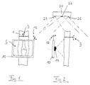
- a device according to the invention is shown schematically in FIG the inside of a patient's joint can be viewed.
- the Leg 1 of the patient should be examined at joint 5.
- the invention designed flat screen 10 held directly in front of the joint, and appears on the screen 10 then an image that contains both image information from the camera's video camera image 14 (Figure 2) also contains image information about the internal anatomical structure, which can be transmitted, for example, by radio transmission from a navigation device. Is to a slice image (MR or CT image) of the patient or his leg 1 beforehand has been created.
- the camera 14 is firmly attached to the rear of the screen 10.
- This type of image display is made possible by the fact that the position of the camera 14 or of the screen 10 in the space around the patient's leg 1 by means of a tracking device is determined.
- this tracking device is an optical tracking device, namely a marker arrangement 12, the position of which by means of the schematic shown navigation system 20 is detected.
- the navigation system 20 comprises for example, two spaced-apart infrared cameras 24, 26 and an infrared light emitter 22. From the two images of the infrared camera 24, 26, the three-dimensional spatial position the marker arrangement 12 and thus also the screen 10 and the permanently installed one Camera 14 can be determined. It is also possible the spatial position of the leg 1 by a to determine the corresponding marker arrangement 3 in the room.
- the position of the screen 10 and camera 14 is now known, the following can be done the position of the current image plane are recorded.
- the camera 14 has a small one Aperture and a shallow depth of field, leaving only the image in a particular focal plane appears sharp. This enables the position of this image plane to be determined and opened transmit an image from the CT or MR imaging method to the screen 10, which also lies precisely in this image plane. It is important that the image ratio the video image is displayed on a 1: 1 scale to the slice image. If so with the device according to the invention, the joint of a patient is viewed for example, the contours of the patient's leg at the top and bottom of the screen.
- the image from the layer acquisition method can now be adapted to this information that it is just above the video image to ensure a realistic impression.
- the viewer of the screen 10 can then do both on the screen View video image, ie a real image, as well as the "inner” image from the layer recording process, in the desired depth and with the transparency set for both pictures.
- These settings can be made via control elements, not shown, for Example toggle switch on the front of the screen.
- the device according to the invention thus gives the viewer the possibility for the first time in direct view of the patient in real time to see the inner treatment area and plan or adjust treatment accordingly. He must have his look no longer turn away from the patient and onto a permanently installed navigation screen see what is particularly beneficial when the patient's reactions to certain medical measures should be checked. Since the "inner" images from the fluoroscopic or slice image recording methods can be designed so that they are virtual 3-D views of the inner body parts, the picture can be made very vivid overall become.
- FIG. 3 shows the sequence of a method as is the case with the invention Device is carried out, in particular the computer of the navigation system performed activity illuminated.
- the top left side of the flowchart affects the process of capturing video while on the right side it captures the image for the inside of the body is explained, using the example of an MR / CT image acquisition.
- the focal plane is first determined, as before was explained.
- the distance of the focal plane to the camera is then determined, whereupon the camera is registered in the navigation system by means of its tracking device. It is now the determination of the spatial position of the camera in relation to the navigation system known.
- the MR / CT image acquisition this will be done in advance, which is what a three-dimensional image reconstruction is carried out on the data obtained. Then the registration the object, for example a patient's body part, carried out in space, d. H. the relation of the object position in space to the MR / CT images is determined. This can be achieved by the spatial detection of an object Marker assembly.
- video image / MR / CT image matching now takes place, i. H. the Both images are computer controlled matched to what the image position and concerns the image size.
- the MR / CT 3D images can be projected onto the video images be superimposed on the image display device and the treating doctor at the Support diagnosis or treatment.
Abstract
Description
Die vorliegende Erfindung betrifft eine Vorrichtung zur Projektion von Patientenbilddaten aus Durchleuchtungs- bzw. Schichtbilderfassungsverfahren auf Videobilder. Die Vorrichtung umfasst eine Bildanzeigevorrichtung, mindestens eine Videokamera und ein computergestütztes Navigationssystem, das die Raumposition der Bildanzeigevorrichtung und/oder der Videokamera sowie die Raumpositionen eines Patientenkörperteils über dort angebrachte Trackingeinrichtungen erfassen kann.The present invention relates to a device for projecting patient image data from X-ray or layer image acquisition method on video images. The device comprises an image display device, at least one video camera and a computer-assisted one Navigation system that the spatial position of the image display device and / or Video camera and the spatial positions of a patient's body part attached there Can capture tracking devices.
Solche Vorrichtungen dienen dazu, einen Mediziner bei der Diagnose bzw. bei der Behandlung eines Patienten visuell zu unterstützen. Es soll die Möglichkeit geschaffen werden, Bilder aus dem Inneren des Patienten mit herkömmlichen Videobildern zu verknüpfen, um Behandlung und Diagnose zu erleichtern.Such devices are used to assist a medical professional in diagnosis or treatment to support a patient visually. The possibility should be created, pictures from the inside of the patient to link with conventional video images to treatment and facilitate diagnosis.
Aus der US-A-5,765,561 ist ein videobasiertes chirurgisches Zielsystem bekannt, für das unter anderem die Verwendung einer getrackten Videokamera vorgeschlagen wird, deren Bilder auf dem stationär angeordneten Bildschirm eines Navigationssystem mit zugeordneten Bildern aus Durchleuchtungs- bzw. Schichtbilderfassungsverfahren überlagert werden. Nachteilig an einer solchen Ausführungsform ist insbesondere, dass der Arzt, der die Bilder betrachten möchte, immer wieder vom Patienten weg und zum Bildschirm des Navigationssystem hinblicken muss. Dabei kann er nicht mehr genau darauf achten, in welcher Stellung nun die Kamera steht, also von welcher Außenposition genau er die überlagerten Bilder erhält. Das System ist deshalb etwas umständlich und ermöglicht keinen direkten Einblick in den Patientenkörperteil.From US-A-5,765,561 a video-based surgical target system is known for which under another suggests the use of a tracked video camera, its images on the stationary screen of a navigation system with assigned images can be overlaid from fluoroscopic or slice image acquisition methods. adversely What is particular about such an embodiment is that the doctor looking at the images want to keep away from the patient and to the navigation system screen must look. He can no longer pay close attention to the position in which the The camera is standing, i.e. from exactly which outside position he receives the superimposed images. The The system is therefore somewhat cumbersome and does not allow a direct view of the patient's body part.
Es ist die Aufgabe der vorliegenden Erfindung, eine Vorrichtung zur Projektion von Patientenbilddaten aus Durchleuchtungs- bzw. Schichtbilderfassungsverfahren auf Videobilder bereitzustellen, welche die oben genannten Nachteile des Standes der Technik überwindet. Insbesondere soll es dem Behandlungspersonal möglich sein, direkt und unmittelbar in Ansicht des Patienten die gewünschten Bilddaten zu erhalten.It is the object of the present invention to provide a device for projecting patient image data to provide video images from fluoroscopic or slice image acquisition methods, which overcomes the above-mentioned disadvantages of the prior art. In particular The treatment staff should be able to see it directly and immediately to obtain the patient's desired image data.
Diese Aufgabe wird erfindungsgemäß dadurch gelöst, dass die Bildanzeigevorrichtung und die Videokamera einander zugeordnet und als tragbare Einheit ausgebildet sind. Mit dieser erfindungsgemäßen Ausgestaltung ergibt sich nun die Möglichkeit für den behandelnden Arzt, die Bildanzeigevorrichtung selbst mit zugeordneter Kamera vor das Patientenkörperteil zu halten und damit im unmittelbaren Aufblick auf den Patienten die gewünschten anatomischen Informationen auszulesen. Dabei ist es möglich, im auf der Bildanzeigevorrichtung dargestellten Bild das Videobild oder das Bild aus dem Durchleuchtungs- bzw. Schichtbilderfassungsverfahren je nach Wunsch mehr oder weniger transparent einzustellen, um so gerade die gewünschten Informationen am deutlichsten in der Gesamtanzeige hervorzuheben. Mit der erfindungsgemäßen Vorrichtung wird ein weiterer Schritt in die Richtung getan, einen "gläsernen Patienten" zu schaffen, und zwar einfach dadurch, dass man die Bildanzeigevorrichtung vor das in Frage kommende Patientenkörperteil hält. Da die Kamerazuordnung zur Bildanzeigevorrichtung über die Trackingeinrichtungen verfolgt wird, ist die Position dieser beiden Elemente immer bekannt, und das Navigationssystem hat Informationen darüber, wie und aus welcher Richtung der Patientenkörperteil angesehen wird. Insbesondere bei der Durchführung minimal invasiver Eingriffe, bei denen keine Freilegung des Eingriffsgebietes erfolgt, bietet die erfindungsgemäße Vorrichtung somit die Möglichkeit für den behandelnden Arzt, sich während der Operation nochmals genau über die Lage der Anatomieteile des Patienten in Kenntnis zu setzen. Auf der Bildanzeigevorrichtung können dabei natürlich auch getrackte bzw. navigierte Instrumente angezeigt werden. Der Arzt muss seinen Blick nicht mehr vom Patienten abwenden, um in erfindungsgemäßer Weise in das Innere des Patientenkörpers hineinzusehen.This object is achieved in that the image display device and the video camera are assigned to one another and are designed as a portable unit. With this The configuration according to the invention now gives the patient the opportunity Doctor, the image display device itself with an associated camera in front of the patient's body part to maintain and thus the desired anatomical view of the patient Read out information. It is possible to on the image display device displayed image the video image or the image from the fluoroscopy or layer image acquisition method depending on your needs, more or less transparent to keep it straight to highlight the desired information most clearly in the overall display. With a further step is taken in the direction of the device according to the invention, a to create "glassy patients" simply by using the image display device stops in front of the patient's body part in question. Since the camera assignment to Image display device is tracked via the tracking devices, the position of these Both elements are always known and the navigation system has information on how and the direction from which the patient's body part is viewed. Especially with the Implementation of minimally invasive interventions, in which no exposure of the area of intervention takes place, the device according to the invention thus offers the possibility for the treating person During the operation, the doctor should carefully review the position of the patient's anatomical parts to notify. Of course, the image display device can also tracked or navigated instruments are displayed. The doctor doesn't have to look turn away more from the patient, in the manner according to the invention, into the interior of the patient's body look into it.
Gemäß einer bevorzugten Ausführungsform der Erfindung ist die Videokamera auf der Rückseite der Bildanzeigevorrichtung angeordnet. Dabei entsteht ein kompaktes Gerät; die Kamera kann vollständig aus dem Blickbereich des Benutzers herausgenommen werden. Grundsätzlich ist anzumerken, dass die Kamera an jeder Stelle der Rückseite der Bildanzeigevorrichtung angebracht, oder in dieser integriert sein kann, zum Beispiel auch im Randbereich der Bildanzeigevorrichtung. According to a preferred embodiment of the invention, the video camera is on the back the image display device. This creates a compact device; the camera can be completely removed from the user's field of vision. in principle it should be noted that the camera at every point on the back of the image display device attached, or can be integrated into this, for example in the edge area of the Image display device.
Bevorzugt steht die Videokamera in vorbestimmter bzw. systembekannter räumlicher Zuordnung zur Bildanzeigevorrichtung und die Trackingeinrichtung ist an der Bildanzeigevorrichtung angeordnet. Durch die vorbestimmte bzw. systembekannte räumliche Zuordnung von Videokamera und Bildanzeigevorrichtung wird die Möglichkeit eröffnet, nur eines dieser beiden Geräte mittels der Trackingeinrichtung zu verfolgen, da man immer genau weiß, wo sich dann das andere Gerät befindet. Es steht dem Konstrukteur dann auch frei, die Trackingeinrichtung entweder an der Bildanzeigevorrichtung selbst oder an der Videokamera anzuordnen, je nachdem wie diese Trackingeinrichtung am bestem vom Navigationssystem erfasst werden kann. Bei optisch basierten Navigationssystemen kann die Trackingeinrichtung eine reflektierende oder aktiv abstrahlende Markeranordnung sein, während es natürlich im Rahmen der vorliegenden Erfindung auch möglich ist, die Navigation über ein Magnettrackingsystem durchzuführen, bei dem Spulen in einem erzeugten Magnetfeld verfolgt werden.The video camera is preferably in a predetermined or system-known spatial assignment to the image display device and the tracking device is on the image display device arranged. The predetermined or system-known spatial assignment of Video camera and image display device opens up the possibility of only one of these two Track devices using the tracking device, since you always know exactly where then the other device is located. The designer is then also free to use the tracking device to be arranged either on the image display device itself or on the video camera, depending on how this tracking device is best captured by the navigation system can. In optically based navigation systems, the tracking device can be a reflective one or be an active radiating marker arrangement, while it is of course within the scope of the The present invention is also possible to navigate via a magnetic tracking system perform in which coils are tracked in a generated magnetic field.
Um die Bildanzeigevorrichtung leicht und gut handhabbar auszugestalten, kann sie als tragbarer LCD-Flachbildschirm ausgestaltet werden.In order to make the image display device easy and easy to handle, it can be used as a portable one LCD flat screen can be designed.
Die Datenübertragung zwischen den einzelnen Geräten der erfindungsgemäßen Vorrichtung kann in unterschiedlicher Weise realisiert werden. Einerseits ist es möglich, die auf die Videobilder zu projizierenden Bilddaten aus dem Durchleuchtungs- bzw. Schichtbilderfassungsverfahren über Funkschnittstellen vom Navigationssystem zur Bildanzeigevorrichtung zu übermitteln, während andererseits auch eine Übermittlung über Datenkabel denkbar ist. Insbesondere vorteilhaft sollte sich im Rahmen der Handhabung der erfindungsgemäßen Vorrichtung eine Ausgestaltung erweisen, bei der die Bildanzeigevorrichtung mit eigener Energieversorgung (Batterie bzw. Akku) versehen ist und eine Funkübertragung erfolgt, da damit die weitgehendste Handhabungsfreiheit erreicht wird.The data transmission between the individual devices of the device according to the invention can be realized in different ways. On the one hand, it is possible to use the video images image data to be projected from the fluoroscopy or slice image acquisition method via radio interfaces from the navigation system to the image display device to transmit, while on the other hand a transmission via data cable is also conceivable. The handling of the device according to the invention should be particularly advantageous show an embodiment in which the image display device with its own power supply (Battery or rechargeable battery) is provided and radio transmission takes place, because with it the greatest freedom of handling is achieved.
Die Videokamera sollte gemäß einer bevorzugten Ausführungsform eine kleine Blende und eine geringe Schärfentiefe aufweisen, damit nur ein kleiner Bereich des erfassten Bildes in der Fokalebene liegt. Mit einer solchen Kamera ist es möglich, den Abstand zwischen dem Bild und der Fokalebene zu ermitteln. Wenn die Raumposition der Kamera aus dem Navigationssystem her bekannt ist und der Abstand zur Bildebene ebenfalls bekannt ist, kann das dem Navigationssystem angeschlossene Computersystem die räumliche Position des Videobildes in Echtzeit errechnen. Damit wird eine Zuordnung von Videobild und Bilddaten aus einer vorher durchgeführten Durchleuchtungs- bzw. Schichtbilderfassung optimal möglich.According to a preferred embodiment, the video camera should have a small aperture and have a shallow depth of field so that only a small area of the captured image in the Focal plane. With such a camera it is possible to determine the distance between the picture and the focal plane. When the spatial position of the camera from the navigation system is known and the distance to the image plane is also known, the can Navigation system connected computer system the spatial position of the video image calculate in real time. This makes an assignment of video image and image data from one Previously performed fluoroscopy or slice image acquisition optimally possible.
Gemäß einer weiteren vorteilhaften Ausgestaltung der erfindungsgemäßen Vorrichtung ist an der Videokamera bzw. an der Bildanzeigevorrichtung eine Datenübertragungseinrichtung angeordnet, mittels der die Informationen über das auf der Bildanzeigevorrichtung angezeigte Bild an das Navigationssystem übertragen werden. Die vom Navigationssystem an die Bildanzeigevorrichtung übermittelten, zu projizierenden Bilddaten werden dann in Größe und Position auf der Bildanzeigevorrichtung so angepasst, dass sie sich mit den Videobildern decken, also eine 1:1-Darstellung beider Bilder in Überdeckung entsteht. Im Navigationssystem kann dazu eine Konturen-Matching-Einheit bereitgestellt werden, mittels der die Überdeckung der Videobilder und der projizierten Bilder realisiert wird, insbesondere über Außenkonturen-Matching für den Patientenkörperteil.According to a further advantageous embodiment of the device according to the invention is on a video transmission device on the video camera or on the image display device arranged by means of which the information about what is displayed on the image display device Image can be transmitted to the navigation system. The from the navigation system to the image display device The transmitted and to be projected image data are then in size and Adjusted position on the image display device so that they coincide with the video images, So a 1: 1 representation of both images overlapped. In the navigation system For this purpose, a contour matching unit can be provided by means of which the overlap the video images and the projected images are realized, in particular via outer contour matching for the patient's body part.
Es soll hier noch angemerkt sein, dass es im Rahmen der Erfindung denkbar und vorteilhaft sein kann, an der tragbaren Einheit verschiedenste Steuerungs- bzw. Befehleingabegeräte für die Veränderung des angezeigten, kombinierten Bildes anzubringen. Beispielsweise kann die Fokalebene sowohl der eingespielten Durchleuchtungs- oder Schichtbilddaten als auch des angezeigten Videobildes durch solche Steuerungselemente zu verändern sein. Wie oben schon angesprochen ist es auch möglich, Steuerungselemente vorzusehen, die den jeweiligen Transparenzgrad eines der Bilder gegenüber dem anderen ändern.It should also be noted here that it is conceivable and advantageous within the scope of the invention can be on the portable unit various control or command input devices for to apply the change to the displayed combined image. For example, the Focal level of the imported fluoroscopic or slice image data as well as the displayed video image can be changed by such control elements. As above When addressed, it is also possible to provide control elements that reflect the respective degree of transparency change one of the images over the other.
An der Kamera bzw. in deren Umgebung an der Bildanzeigevorrichtung ist vorteilhafterweise eine Beleuchtungsvorrichtung für den Patientenkörperteil vorgesehen, speziell beispielsweise als Ringlicht (LEDs, Lampen, Leuchtstoffröhren).On the camera or in its vicinity on the image display device is advantageous a lighting device is provided for the patient's body part, especially for example as ring light (LEDs, lamps, fluorescent tubes).
Die Erfindung wird im Weiteren anhand einer Ausführungsform näher erläutert. In den hierzu bereitgestellten Zeichnungen zeigen:
- Figur 1
- eine schematische Darstellung für die Verwendung einer erfindungsgemäßen Vorrichtung zur Ansicht eines Patienten-Kniegelenks in der Aufsicht;
- Figur 2
- eine seitliche Ansicht der Vorrichtung nach Figur 1 mit schematisch dargestelltem Navigationssystem; und
Figur 3- ein Ablaufdiagramm für den Betrieb der erfindungsgemäßen Vorrichtung.
- Figure 1
- a schematic representation of the use of a device according to the invention for viewing a patient's knee joint in supervision;
- Figure 2
- a side view of the device of Figure 1 with a schematically illustrated navigation system; and
- Figure 3
- a flow chart for the operation of the device according to the invention.
In der Figur 1 ist schematisch eine erfindungsgemäße Vorrichtung dargestellt, mit der beispielsweise
in das Innere eines Gelenks eines Patienten Einsicht genommen werden kann. Das
Bein 1 des Patienten soll am Gelenk 5 untersucht werden. Hierzu wird der erfindungsgemäß
ausgestaltete Flachbildschirm 10 direkt vor das Gelenk gehalten, und auf dem Schirm 10 erscheint
dann ein Bild, das sowohl Bildinformationen aus dem Videokamerabild der Kamera
14 (Figur 2) enthält als auch Bildinformationen über die innere anatomische Struktur, welche
beispielsweise per Funkübertragung von einem Navigationsgerät übermittelt werden. Dazu ist
vorab von dem Patienten bzw. von dessen Bein 1 eine Schichtbildaufnahme (MR- oder CT-Aufnahme)
erstellt worden.A device according to the invention is shown schematically in FIG
the inside of a patient's joint can be viewed. The
Leg 1 of the patient should be examined at
Wie besser in Figur 2 deutlich wird, befindet sich die Kamera 14 fest angebracht an der Rückseite
des Bildschirms 10.As can be seen better in FIG. 2, the
Möglich wird diese Art der Bilddarstellung dadurch, dass die Position der Kamera 14 bzw.
des Bildschirms 10 im Raum um das Bein 1 des Patienten herum mittels einer Trackingeinrichtung
ermittelt wird. Diese Trackingeinrichtung ist im vorliegenden Fall eine optische Trackingeinrichtung,
nämlich eine Markeranordnung 12, deren Position mittels des schematisch
dargestellten Navigationssystems 20 erfasst wird. Das Navigationssystem 20 umfasst hierzu
beispielsweise zwei beabstandete Infrarot-Kameras 24, 26 und einen Infrarot-Lichtabstrahler
22. Aus den beiden Bildern der Infrarot-Kamera 24, 26 kann die dreidimensionale Raumposition
der Markeranordnung 12 und damit auch des Bildschirms 10 und der fest installierten
Kamera 14 ermittelt werden. Es ist ferner möglich die Raumposition des Beines 1 durch eine
entsprechende Markeranordnung 3 im Raum zu ermitteln.This type of image display is made possible by the fact that the position of the
Wenn nun die Position von Bildschirm 10 und Kamera 14 bekannt ist, kann in folgender Weise
die Position der aktuellen Bildebene erfasst werden. Die Kamera 14 hat nämlich eine kleine
Blende und eine geringe Schärfentiefe, so dass nur das Bild in einer bestimmten Fokalebene
scharf erscheint. Es lässt sich hierdurch die Position dieser Bildebene ermitteln und auf
dem Bildschirm 10 ein Bild aus dem CT- oder MR-Aufnahmeverfahren übertragen, welche
ebenfalls gerade in dieser Bildebene liegt. Wichtig ist hierbei, dass das Abbildungsverhältnis
des Videobildes in einem 1:1-Maßstab zum Schichtaufnahmebild angezeigt wird. Wenn nun
mit der erfindungsgemäßen Vorrichtung das Gelenk eines Patienten betrachtet wird, sieht man
beispielsweise am oberen und unteren Bildschirmrand die Konturen des Patientenbeines. Mit
dieser Information kann nunmehr das Bild aus dem Schichtaufnahmeverfahren so angepasst
werden, dass es gerade über dem Videobild liegt, um einen realistischen Eindruck zu gewährleisten.
Der Betrachter des Bildschirms 10 kann dann auf dem Bildschirm sowohl das
Videobild, also ein echtes Bild, ansehen, als auch das "innere" Bild aus dem Schichtaufnahmeverfahren,
und zwar in jeweils gewünschter Tiefe und in jeweils eingestellter Transparenz
für beide Bilder. Diese Einstellungen können über nicht dargestellte Steuerungsorgane, zum
Beispiel Kippschalter an der Bildschirmvorderseite, getroffen werden.If the position of the
Die erfindungsgemäße Vorrichtung gibt damit dem Betrachter erstmals die Möglichkeit, in direktem Aufblick auf den Patienten in Echtzeit in den inneren Behandlungsbereich hineinzusehen und die Behandlung entsprechend zu planen oder anzupassen. Er muss seinen Blick nicht mehr vom Patienten abwenden und auf einen fest installierten Navigationsbildschirm sehen, was insbesondere von Vorteil ist, wenn die Reaktionen des Patienten auf bestimmte ärztliche Maßnahmen überprüft werden sollen. Da die "inneren" Bilder aus den Durchleuchtungs- bzw. Schichtbildaufnahmeverfahren so gestaltet werden können, dass sie virtuell 3-D-Ansichten der inneren Körperteile darstellen, kann das Bild insgesamt sehr anschaulich gemacht werden.The device according to the invention thus gives the viewer the possibility for the first time in direct view of the patient in real time to see the inner treatment area and plan or adjust treatment accordingly. He must have his look no longer turn away from the patient and onto a permanently installed navigation screen see what is particularly beneficial when the patient's reactions to certain medical measures should be checked. Since the "inner" images from the fluoroscopic or slice image recording methods can be designed so that they are virtual 3-D views of the inner body parts, the picture can be made very vivid overall become.
Obwohl also nicht vor Ort ein Durchleuchtungs- bzw. Schichtbild aufgenommen wird, entsteht somit ein virtuell "gläserner Patient".So although a fluoroscopy or slice image is not taken on site, it is created thus a virtually "transparent patient".
In der Figur 3 ist der Ablauf eines Verfahrens aufgezeigt, wie es mit der erfindungsgemäßen Vorrichtung durchgeführt wird, insbesondere wird hierbei die vom Computer des Navigationssystems durchgeführte Tätigkeit beleuchtet. Die obere linke Seite des Ablaufdiagramms betrifft die Vorgänge bei der Videobilderfassung, während auf der rechten Seite die Bilderfassung für das Körperinnere erläutert wird, und zwar am Beispiel einer MR-/CT-Bilderfassung. Bei der Videobilderfassung wird zunächst die Fokalebene bestimmt, wie dies vorher schon erläutert wurde. Danach erfolgt eine Bestimmung des Abstandes der Fokalebene zur Kamera, worauf die Kamera mittels ihrer Trackingeinrichtung im Navigationssystem registriert wird. Es ist nun die Bestimmung der Raumposition der Kamera gegenüber dem Navigationssystem bekannt.FIG. 3 shows the sequence of a method as is the case with the invention Device is carried out, in particular the computer of the navigation system performed activity illuminated. The top left side of the flowchart affects the process of capturing video while on the right side it captures the image for the inside of the body is explained, using the example of an MR / CT image acquisition. When capturing video images, the focal plane is first determined, as before was explained. The distance of the focal plane to the camera is then determined, whereupon the camera is registered in the navigation system by means of its tracking device. It is now the determination of the spatial position of the camera in relation to the navigation system known.
Was die MR-/CT-Bilderfassung betrifft, so wird diese zunächst vorab erfolgen, worauf aus den erhaltenen Daten eine dreidimensionale Bildrekonstruktion erfolgt. Dann wird die Registrierung des Objektes, beispielsweise eines Patientenkörperteils, im Raum durchgeführt, d. h. es erfolgt eine Bestimmung der Relation der Objektposition im Raum zu den MR-/CT-Bildern. Realisiert werden kann dies durch die räumliche Erfassung einer am Objekt befindlichen Markierungsanordnung.As for the MR / CT image acquisition, this will be done in advance, which is what a three-dimensional image reconstruction is carried out on the data obtained. Then the registration the object, for example a patient's body part, carried out in space, d. H. the relation of the object position in space to the MR / CT images is determined. This can be achieved by the spatial detection of an object Marker assembly.
Wenn die oben aufgeführten Schritte der Videobilderfassung und MR-/CT-Bildverarbeitung
durchgeführt worden sind, erfolgt nunmehr ein Videobild-/MR-/CT-Bild-Matching, d. h. die
beiden Bilder werden computergesteuert in Übereinstimmung gebracht, was die Bildposition
und die Bildgröße betrifft. Danach können die MR-/CT-3D-Bilder projiziert auf die Videobilder
auf der Bildanzeigevorrichtung überlagert werden und den behandelnden Arzt bei der
Diagnose bzw. Behandlung unterstützen.If the above steps of video imaging and MR / CT image processing
have been carried out, video image / MR / CT image matching now takes place, i. H. the
Both images are computer controlled matched to what the image position
and concerns the image size. After that, the MR /
Claims (11)
Priority Applications (9)
| Application Number | Priority Date | Filing Date | Title |
|---|---|---|---|
| EP01129381A EP1321105B1 (en) | 2001-12-18 | 2001-12-18 | Superposition of patient X-ray or scanning imaging data and superficial video images |
| DE50100535T DE50100535D1 (en) | 2001-12-18 | 2001-12-18 | Projection of patient image data from fluoroscopy or slice image acquisition methods onto surface video images |
| DE50101677T DE50101677D1 (en) | 2001-12-18 | 2001-12-18 | Projection of patient image data from fluoroscopic or slice image acquisition methods onto video images |
| ES03008762T ES2215985T3 (en) | 2001-12-18 | 2001-12-18 | X-RAY IMAGE DATA SUPERPOSITION OF A PATIENT, OR SCANNER IMAGE DATA AND VIDEO IMAGES. |
| ES01129381T ES2203577T3 (en) | 2001-12-18 | 2001-12-18 | SUPERPOSITION OF SCANNER OR X-RAY IMAGE DATA OF A PATIENT, AND SURFACE VIDEO IMAGES. |
| EP03008762A EP1327421B1 (en) | 2001-12-18 | 2001-12-18 | Superposition of patient X-ray or scanning imaging data and video images |
| AT01129381T ATE247431T1 (en) | 2001-12-18 | 2001-12-18 | PROJECTION OF PATIENT IMAGE DATA FROM TRANSLUCLOSURE OR LAYER IMAGE CAPTURE METHOD ON SURFACE VIDEO IMAGES |
| AT03008762T ATE261273T1 (en) | 2001-12-18 | 2001-12-18 | PROJECTION OF PATIENT IMAGE DATA FROM TRANSLOX OR LAYER IMAGE CAPTURE METHOD ON VIDEO IMAGES |
| US10/134,977 US7050845B2 (en) | 2001-12-18 | 2002-04-29 | Projecting patient image data from radioscopic imaging methods and/or tomographic imaging methods onto video images |
Applications Claiming Priority (1)
| Application Number | Priority Date | Filing Date | Title |
|---|---|---|---|
| EP01129381A EP1321105B1 (en) | 2001-12-18 | 2001-12-18 | Superposition of patient X-ray or scanning imaging data and superficial video images |
Related Child Applications (1)
| Application Number | Title | Priority Date | Filing Date |
|---|---|---|---|
| EP03008762A Division EP1327421B1 (en) | 2001-12-18 | 2001-12-18 | Superposition of patient X-ray or scanning imaging data and video images |
Publications (2)
| Publication Number | Publication Date |
|---|---|
| EP1321105A1 true EP1321105A1 (en) | 2003-06-25 |
| EP1321105B1 EP1321105B1 (en) | 2003-08-20 |
Family
ID=8179493
Family Applications (2)
| Application Number | Title | Priority Date | Filing Date |
|---|---|---|---|
| EP01129381A Expired - Lifetime EP1321105B1 (en) | 2001-12-18 | 2001-12-18 | Superposition of patient X-ray or scanning imaging data and superficial video images |
| EP03008762A Expired - Lifetime EP1327421B1 (en) | 2001-12-18 | 2001-12-18 | Superposition of patient X-ray or scanning imaging data and video images |
Family Applications After (1)
| Application Number | Title | Priority Date | Filing Date |
|---|---|---|---|
| EP03008762A Expired - Lifetime EP1327421B1 (en) | 2001-12-18 | 2001-12-18 | Superposition of patient X-ray or scanning imaging data and video images |
Country Status (5)
| Country | Link |
|---|---|
| US (1) | US7050845B2 (en) |
| EP (2) | EP1321105B1 (en) |
| AT (2) | ATE261273T1 (en) |
| DE (2) | DE50100535D1 (en) |
| ES (2) | ES2203577T3 (en) |
Cited By (5)
| Publication number | Priority date | Publication date | Assignee | Title |
|---|---|---|---|---|
| US5980168A (en) * | 1996-11-26 | 1999-11-09 | Hilti Aktiengesellschaft | Hollow crown drill |
| US7203277B2 (en) | 2003-04-25 | 2007-04-10 | Brainlab Ag | Visualization device and method for combined patient and object image data |
| US7463823B2 (en) | 2003-07-24 | 2008-12-09 | Brainlab Ag | Stereoscopic visualization device for patient image data and video images |
| DE102011083634A1 (en) * | 2011-09-28 | 2013-03-28 | Siemens Aktiengesellschaft | Apparatus and method for image display |
| US9925017B2 (en) | 2009-03-31 | 2018-03-27 | Brainlab Ag | Medical navigation image output comprising virtual primary images and actual secondary images |
Families Citing this family (55)
| Publication number | Priority date | Publication date | Assignee | Title |
|---|---|---|---|---|
| ATE355030T1 (en) * | 2003-04-25 | 2006-03-15 | Brainlab Ag | VISUALIZATION DEVICE FOR COMBINED PATIENT AND OBJECT IMAGE DATA WITH AN INPUT DEVICE AND VISUALIZATION METHOD |
| US10610406B2 (en) * | 2004-07-21 | 2020-04-07 | Vanderbilt University | Drug delivery device and applications of same |
| US7398116B2 (en) | 2003-08-11 | 2008-07-08 | Veran Medical Technologies, Inc. | Methods, apparatuses, and systems useful in conducting image guided interventions |
| US8150495B2 (en) | 2003-08-11 | 2012-04-03 | Veran Medical Technologies, Inc. | Bodily sealants and methods and apparatus for image-guided delivery of same |
| DE202004014857U1 (en) * | 2003-09-29 | 2005-04-21 | Fraunhofer-Gesellschaft zur Förderung der angewandten Forschung e.V. | Device for the virtual situation analysis of at least one intracorporeally introduced into a body medical instrument |
| CA2974143C (en) * | 2004-02-20 | 2020-11-10 | University Of Florida Research Foundation, Inc. | System for delivering conformal radiation therapy while simultaneously imaging soft tissue |
| DE502004004650D1 (en) * | 2004-07-28 | 2007-09-27 | Brainlab Ag | Stereoscopic visualization device for patient image data and video images |
| EP1924198B1 (en) | 2005-09-13 | 2019-04-03 | Veran Medical Technologies, Inc. | Apparatus for image guided accuracy verification |
| US20070066881A1 (en) | 2005-09-13 | 2007-03-22 | Edwards Jerome R | Apparatus and method for image guided accuracy verification |
| US8442281B2 (en) * | 2006-04-28 | 2013-05-14 | The Invention Science Fund I, Llc | Artificially displaying information relative to a body |
| WO2008071014A1 (en) * | 2006-12-15 | 2008-06-19 | Ao Technology Ag | Method and device for computer assisted distal locking of intramedullary nails |
| EP2248462B1 (en) * | 2009-05-06 | 2016-04-20 | Brainlab AG | Method for portraying image data of a patient body part |
| US8876830B2 (en) * | 2009-08-13 | 2014-11-04 | Zimmer, Inc. | Virtual implant placement in the OR |
| EP2566392A4 (en) | 2010-05-04 | 2015-07-15 | Pathfinder Therapeutics Inc | System and method for abdominal surface matching using pseudo-features |
| US20130303887A1 (en) | 2010-08-20 | 2013-11-14 | Veran Medical Technologies, Inc. | Apparatus and method for four dimensional soft tissue navigation |
| EP2452649A1 (en) * | 2010-11-12 | 2012-05-16 | Deutsches Krebsforschungszentrum Stiftung des Öffentlichen Rechts | Visualization of anatomical data by augmented reality |
| US8810640B2 (en) | 2011-05-16 | 2014-08-19 | Ut-Battelle, Llc | Intrinsic feature-based pose measurement for imaging motion compensation |
| KR101495083B1 (en) * | 2011-12-28 | 2015-02-24 | 삼성메디슨 주식회사 | Method for proving bodymarker and ultrasound diagnostic apparatus thereof |
| EP4056111A3 (en) | 2012-02-22 | 2022-12-07 | Veran Medical Technologies, Inc. | Systems, methods, and devices for four dimensional soft tissue navigation |
| US10561861B2 (en) | 2012-05-02 | 2020-02-18 | Viewray Technologies, Inc. | Videographic display of real-time medical treatment |
| US9439622B2 (en) | 2012-05-22 | 2016-09-13 | Covidien Lp | Surgical navigation system |
| US9498182B2 (en) | 2012-05-22 | 2016-11-22 | Covidien Lp | Systems and methods for planning and navigation |
| US9439623B2 (en) | 2012-05-22 | 2016-09-13 | Covidien Lp | Surgical planning system and navigation system |
| US8750568B2 (en) | 2012-05-22 | 2014-06-10 | Covidien Lp | System and method for conformal ablation planning |
| US9439627B2 (en) | 2012-05-22 | 2016-09-13 | Covidien Lp | Planning system and navigation system for an ablation procedure |
| AU2013334064A1 (en) | 2012-10-26 | 2015-05-14 | Viewray Technologies, Inc. | Assessment and improvement of treatment using imaging of physiological responses to radiation therapy |
| CN103892861B (en) * | 2012-12-28 | 2016-05-11 | 北京思创贯宇科技开发有限公司 | A kind of analogue navigation system and method merging based on CT-XA image multi-dimensional |
| US9446263B2 (en) | 2013-03-15 | 2016-09-20 | Viewray Technologies, Inc. | Systems and methods for linear accelerator radiotherapy with magnetic resonance imaging |
| US10561469B2 (en) | 2014-02-28 | 2020-02-18 | Sony Corporation | Robot arm apparatus and robot arm control method |
| FR3019727A1 (en) * | 2014-04-15 | 2015-10-16 | Bcom | METHOD FOR LOCATING MEDICAL OBJECTS, DEVICE, SYSTEM AND COMPUTER PROGRAM THEREOF |
| US20150305612A1 (en) | 2014-04-23 | 2015-10-29 | Mark Hunter | Apparatuses and methods for registering a real-time image feed from an imaging device to a steerable catheter |
| US20150305650A1 (en) | 2014-04-23 | 2015-10-29 | Mark Hunter | Apparatuses and methods for endobronchial navigation to and confirmation of the location of a target tissue and percutaneous interception of the target tissue |
| US10013808B2 (en) | 2015-02-03 | 2018-07-03 | Globus Medical, Inc. | Surgeon head-mounted display apparatuses |
| US20170119329A1 (en) | 2015-10-28 | 2017-05-04 | General Electric Company | Real-time patient image overlay display and device navigation system and method |
| AU2016361432A1 (en) | 2015-11-24 | 2018-06-07 | Viewray Technologies, Inc. | Radiation beam collimating systems and methods |
| KR20180099702A (en) | 2015-12-31 | 2018-09-05 | 스트리커 코포레이션 | System and method for performing surgery on a patient at a target site defined by a virtual object |
| EP3423153B1 (en) | 2016-03-02 | 2021-05-19 | ViewRay Technologies, Inc. | Particle therapy with magnetic resonance imaging |
| AU2017281519A1 (en) | 2016-06-22 | 2019-01-24 | Viewray Technologies, Inc. | Magnetic resonance imaging at low field strength |
| EP3554635B1 (en) | 2016-12-13 | 2021-01-20 | ViewRay Technologies, Inc. | Radiation therapy systems |
| CN116036499A (en) | 2017-12-06 | 2023-05-02 | 优瑞技术公司 | Optimization of multi-modality radiation therapy |
| US20190254753A1 (en) | 2018-02-19 | 2019-08-22 | Globus Medical, Inc. | Augmented reality navigation systems for use with robotic surgical systems and methods of their use |
| US11209509B2 (en) | 2018-05-16 | 2021-12-28 | Viewray Technologies, Inc. | Resistive electromagnet systems and methods |
| WO2020033947A1 (en) | 2018-08-10 | 2020-02-13 | Covidien Lp | Systems for ablation visualization |
| EP3692939B1 (en) | 2019-02-07 | 2021-07-14 | Stryker European Operations Limited | Surgical systems for facilitating tissue treatment |
| CN110368007A (en) * | 2019-04-12 | 2019-10-25 | 北京诺亦腾科技有限公司 | Splice control method between a kind of object |
| US11721014B2 (en) | 2019-11-15 | 2023-08-08 | GE Precision Healthcare LLC | Methods and systems for a field-of-view preview |
| US11464581B2 (en) | 2020-01-28 | 2022-10-11 | Globus Medical, Inc. | Pose measurement chaining for extended reality surgical navigation in visible and near infrared spectrums |
| US11382699B2 (en) | 2020-02-10 | 2022-07-12 | Globus Medical Inc. | Extended reality visualization of optical tool tracking volume for computer assisted navigation in surgery |
| US11207150B2 (en) | 2020-02-19 | 2021-12-28 | Globus Medical, Inc. | Displaying a virtual model of a planned instrument attachment to ensure correct selection of physical instrument attachment |
| US11607277B2 (en) | 2020-04-29 | 2023-03-21 | Globus Medical, Inc. | Registration of surgical tool with reference array tracked by cameras of an extended reality headset for assisted navigation during surgery |
| US11153555B1 (en) | 2020-05-08 | 2021-10-19 | Globus Medical Inc. | Extended reality headset camera system for computer assisted navigation in surgery |
| US11382700B2 (en) | 2020-05-08 | 2022-07-12 | Globus Medical Inc. | Extended reality headset tool tracking and control |
| US11510750B2 (en) | 2020-05-08 | 2022-11-29 | Globus Medical, Inc. | Leveraging two-dimensional digital imaging and communication in medicine imagery in three-dimensional extended reality applications |
| US11737831B2 (en) | 2020-09-02 | 2023-08-29 | Globus Medical Inc. | Surgical object tracking template generation for computer assisted navigation during surgical procedure |
| US11586837B2 (en) * | 2020-10-22 | 2023-02-21 | Stryker Corporation | Systems and methods for capturing, displaying, and manipulating medical images and videos |
Citations (5)
| Publication number | Priority date | Publication date | Assignee | Title |
|---|---|---|---|---|
| EP0672389A2 (en) * | 1994-03-17 | 1995-09-20 | Roke Manor Research Limited | Video-based system for computer assisted surgery and localisation |
| WO1996020421A1 (en) * | 1994-12-23 | 1996-07-04 | Leica Ag | Microscope, in particular a stereomicroscope, and a method of superimposing two images |
| US5694142A (en) * | 1993-06-21 | 1997-12-02 | General Electric Company | Interactive digital arrow (d'arrow) three-dimensional (3D) pointing |
| US5765561A (en) | 1994-10-07 | 1998-06-16 | Medical Media Systems | Video-based surgical targeting system |
| US6038467A (en) * | 1997-01-24 | 2000-03-14 | U.S. Philips Corporation | Image display system and image guided surgery system |
Family Cites Families (10)
| Publication number | Priority date | Publication date | Assignee | Title |
|---|---|---|---|---|
| DE4304571A1 (en) * | 1993-02-16 | 1994-08-18 | Mdc Med Diagnostic Computing | Procedures for planning and controlling a surgical procedure |
| US5961456A (en) * | 1993-05-12 | 1999-10-05 | Gildenberg; Philip L. | System and method for displaying concurrent video and reconstructed surgical views |
| US5526812A (en) * | 1993-06-21 | 1996-06-18 | General Electric Company | Display system for enhancing visualization of body structures during medical procedures |
| DE29521895U1 (en) * | 1994-10-07 | 1998-09-10 | Univ St Louis | Surgical navigation system comprising reference and localization frames |
| US6477400B1 (en) * | 1998-08-20 | 2002-11-05 | Sofamor Danek Holdings, Inc. | Fluoroscopic image guided orthopaedic surgery system with intraoperative registration |
| DE10015826A1 (en) * | 2000-03-30 | 2001-10-11 | Siemens Ag | Image generating system for medical surgery |
| WO2002029700A2 (en) * | 2000-10-05 | 2002-04-11 | Siemens Corporate Research, Inc. | Intra-operative image-guided neurosurgery with augmented reality visualization |
| DE50002672D1 (en) * | 2000-12-19 | 2003-07-31 | Brainlab Ag | Method and device for navigation-assisted dental treatment |
| US6856324B2 (en) * | 2001-03-27 | 2005-02-15 | Siemens Corporate Research, Inc. | Augmented reality guided instrument positioning with guiding graphics |
| US6919867B2 (en) * | 2001-03-29 | 2005-07-19 | Siemens Corporate Research, Inc. | Method and apparatus for augmented reality visualization |
-
2001
- 2001-12-18 AT AT03008762T patent/ATE261273T1/en not_active IP Right Cessation
- 2001-12-18 EP EP01129381A patent/EP1321105B1/en not_active Expired - Lifetime
- 2001-12-18 ES ES01129381T patent/ES2203577T3/en not_active Expired - Lifetime
- 2001-12-18 DE DE50100535T patent/DE50100535D1/en not_active Expired - Lifetime
- 2001-12-18 ES ES03008762T patent/ES2215985T3/en not_active Expired - Lifetime
- 2001-12-18 EP EP03008762A patent/EP1327421B1/en not_active Expired - Lifetime
- 2001-12-18 DE DE50101677T patent/DE50101677D1/en not_active Expired - Lifetime
- 2001-12-18 AT AT01129381T patent/ATE247431T1/en not_active IP Right Cessation
-
2002
- 2002-04-29 US US10/134,977 patent/US7050845B2/en not_active Expired - Lifetime
Patent Citations (5)
| Publication number | Priority date | Publication date | Assignee | Title |
|---|---|---|---|---|
| US5694142A (en) * | 1993-06-21 | 1997-12-02 | General Electric Company | Interactive digital arrow (d'arrow) three-dimensional (3D) pointing |
| EP0672389A2 (en) * | 1994-03-17 | 1995-09-20 | Roke Manor Research Limited | Video-based system for computer assisted surgery and localisation |
| US5765561A (en) | 1994-10-07 | 1998-06-16 | Medical Media Systems | Video-based surgical targeting system |
| WO1996020421A1 (en) * | 1994-12-23 | 1996-07-04 | Leica Ag | Microscope, in particular a stereomicroscope, and a method of superimposing two images |
| US6038467A (en) * | 1997-01-24 | 2000-03-14 | U.S. Philips Corporation | Image display system and image guided surgery system |
Cited By (6)
| Publication number | Priority date | Publication date | Assignee | Title |
|---|---|---|---|---|
| US5980168A (en) * | 1996-11-26 | 1999-11-09 | Hilti Aktiengesellschaft | Hollow crown drill |
| US7203277B2 (en) | 2003-04-25 | 2007-04-10 | Brainlab Ag | Visualization device and method for combined patient and object image data |
| US7463823B2 (en) | 2003-07-24 | 2008-12-09 | Brainlab Ag | Stereoscopic visualization device for patient image data and video images |
| US9925017B2 (en) | 2009-03-31 | 2018-03-27 | Brainlab Ag | Medical navigation image output comprising virtual primary images and actual secondary images |
| DE102011083634A1 (en) * | 2011-09-28 | 2013-03-28 | Siemens Aktiengesellschaft | Apparatus and method for image display |
| DE102011083634B4 (en) * | 2011-09-28 | 2021-05-06 | Siemens Healthcare Gmbh | Apparatus and method for image display |
Also Published As
| Publication number | Publication date |
|---|---|
| ES2203577T3 (en) | 2004-04-16 |
| US7050845B2 (en) | 2006-05-23 |
| EP1327421B1 (en) | 2004-03-10 |
| ES2215985T3 (en) | 2004-10-16 |
| EP1321105B1 (en) | 2003-08-20 |
| US20030114741A1 (en) | 2003-06-19 |
| ATE261273T1 (en) | 2004-03-15 |
| ATE247431T1 (en) | 2003-09-15 |
| DE50100535D1 (en) | 2003-09-25 |
| EP1327421A1 (en) | 2003-07-16 |
| DE50101677D1 (en) | 2004-04-15 |
Similar Documents
| Publication | Publication Date | Title |
|---|---|---|
| EP1321105B1 (en) | Superposition of patient X-ray or scanning imaging data and superficial video images | |
| EP2082687B1 (en) | Overlaid presentation of exposures | |
| DE19917867B4 (en) | Method and device for image support in the treatment of treatment objectives with integration of X-ray detection and navigation system | |
| EP3449830B1 (en) | Control of a medical imaging device | |
| DE102011078212B4 (en) | Method and device for displaying an object | |
| DE3717871C3 (en) | Method and device for reproducible visual representation of a surgical intervention | |
| EP1342488B1 (en) | Method and device for repeated relative repositioning of a patient | |
| DE19751761B4 (en) | System and method for currently accurate detection of treatment targets | |
| DE112008001217B4 (en) | X-ray CT imaging device | |
| DE69819289T2 (en) | IMAGE GUIDED SURGICAL SYSTEM | |
| DE102005062582B4 (en) | Imaging system and method for making x-ray and optical images | |
| DE102009038021A1 (en) | Image processing system with an additional to be processed together with the image information scale information | |
| DE102005023194A1 (en) | Method for expanding the display area of 2D image recordings of an object area | |
| DE19848765A1 (en) | Three-dimensional positioning reference insertion method for video camera image e.g. for positioning patient for computer tomography, uses computer-aided evaluation of infra-red images of space viewed by video camera | |
| EP1121900A2 (en) | Method of determining the position of a medical instrument | |
| DE19956814A1 (en) | Operating device shape detection involves acquiring x-ray image projection, classifying external shape of device in navigation system using position marker orientation in projection | |
| DE19944516A1 (en) | Three dimensional shape measurement system for computer tomography set up uses successive focussing of camera on set of planes | |
| DE19941149A1 (en) | Radiotherapy mapping arrangement, e.g. for cancer; has computer tomographic simulator, X-ray simulator, determination arrangement, superposition and display device | |
| DE10015826A1 (en) | Image generating system for medical surgery | |
| WO2008058520A2 (en) | Apparatus for supplying images to an operator | |
| DE102005026220A1 (en) | Subject e.g. person, examination region`s e.g. spinal column, medical image data acquisition, analysis and representation performing method, involves displaying part of data set at display with graphical representation | |
| EP1114621A2 (en) | Apparatus for displaying images | |
| DE102006060421A1 (en) | Apparatus for performing minimally invasive diagnoses and possibly additional therapeutic interventions inside the body of a patient | |
| EP0681251A2 (en) | Method of operating an operation microscope | |
| DE102011005659B4 (en) | Method for the geometrically correct assignment of X-ray images |
Legal Events
| Date | Code | Title | Description |
|---|---|---|---|
| GRAH | Despatch of communication of intention to grant a patent |
Free format text: ORIGINAL CODE: EPIDOS IGRA |
|
| GRAH | Despatch of communication of intention to grant a patent |
Free format text: ORIGINAL CODE: EPIDOS IGRA |
|
| PUAI | Public reference made under article 153(3) epc to a published international application that has entered the european phase |
Free format text: ORIGINAL CODE: 0009012 |
|
| 17P | Request for examination filed |
Effective date: 20011218 |
|
| AK | Designated contracting states |
Designated state(s): AT BE CH CY DE DK ES FI FR GB GR IE IT LI LU MC NL PT SE TR |
|
| AX | Request for extension of the european patent |
Extension state: AL LT LV MK RO SI |
|
| GRAA | (expected) grant |
Free format text: ORIGINAL CODE: 0009210 |
|
| AK | Designated contracting states |
Designated state(s): AT BE CH CY DE DK ES FI FR GB GR IE IT LI LU MC NL PT SE TR |
|
| PG25 | Lapsed in a contracting state [announced via postgrant information from national office to epo] |
Ref country code: FI Free format text: LAPSE BECAUSE OF FAILURE TO SUBMIT A TRANSLATION OF THE DESCRIPTION OR TO PAY THE FEE WITHIN THE PRESCRIBED TIME-LIMIT Effective date: 20030820 Ref country code: TR Free format text: LAPSE BECAUSE OF FAILURE TO SUBMIT A TRANSLATION OF THE DESCRIPTION OR TO PAY THE FEE WITHIN THE PRESCRIBED TIME-LIMIT Effective date: 20030820 Ref country code: NL Free format text: LAPSE BECAUSE OF FAILURE TO SUBMIT A TRANSLATION OF THE DESCRIPTION OR TO PAY THE FEE WITHIN THE PRESCRIBED TIME-LIMIT Effective date: 20030820 Ref country code: IE Free format text: LAPSE BECAUSE OF FAILURE TO SUBMIT A TRANSLATION OF THE DESCRIPTION OR TO PAY THE FEE WITHIN THE PRESCRIBED TIME-LIMIT Effective date: 20030820 |
|
| REG | Reference to a national code |
Ref country code: GB Ref legal event code: FG4D Free format text: NOT ENGLISH |
|
| REG | Reference to a national code |
Ref country code: CH Ref legal event code: EP |
|
| GBT | Gb: translation of ep patent filed (gb section 77(6)(a)/1977) | ||
| REG | Reference to a national code |
Ref country code: CH Ref legal event code: NV Representative=s name: RIEDERER HASLER & PARTNER PATENTANWAELTE AG |
|
| REG | Reference to a national code |
Ref country code: IE Ref legal event code: FG4D Free format text: GERMAN |
|
| REF | Corresponds to: |
Ref document number: 50100535 Country of ref document: DE Date of ref document: 20030925 Kind code of ref document: P |
|
| PG25 | Lapsed in a contracting state [announced via postgrant information from national office to epo] |
Ref country code: DK Free format text: LAPSE BECAUSE OF FAILURE TO SUBMIT A TRANSLATION OF THE DESCRIPTION OR TO PAY THE FEE WITHIN THE PRESCRIBED TIME-LIMIT Effective date: 20031120 Ref country code: GR Free format text: LAPSE BECAUSE OF FAILURE TO SUBMIT A TRANSLATION OF THE DESCRIPTION OR TO PAY THE FEE WITHIN THE PRESCRIBED TIME-LIMIT Effective date: 20031120 Ref country code: SE Free format text: LAPSE BECAUSE OF FAILURE TO SUBMIT A TRANSLATION OF THE DESCRIPTION OR TO PAY THE FEE WITHIN THE PRESCRIBED TIME-LIMIT Effective date: 20031120 |
|
| PG25 | Lapsed in a contracting state [announced via postgrant information from national office to epo] |
Ref country code: LU Free format text: LAPSE BECAUSE OF NON-PAYMENT OF DUE FEES Effective date: 20031218 Ref country code: CY Free format text: LAPSE BECAUSE OF FAILURE TO SUBMIT A TRANSLATION OF THE DESCRIPTION OR TO PAY THE FEE WITHIN THE PRESCRIBED TIME-LIMIT Effective date: 20031218 |
|
| PG25 | Lapsed in a contracting state [announced via postgrant information from national office to epo] |
Ref country code: MC Free format text: LAPSE BECAUSE OF NON-PAYMENT OF DUE FEES Effective date: 20031231 |
|
| PG25 | Lapsed in a contracting state [announced via postgrant information from national office to epo] |
Ref country code: PT Free format text: LAPSE BECAUSE OF FAILURE TO SUBMIT A TRANSLATION OF THE DESCRIPTION OR TO PAY THE FEE WITHIN THE PRESCRIBED TIME-LIMIT Effective date: 20040120 |
|
| LTIE | Lt: invalidation of european patent or patent extension |
Effective date: 20030820 |
|
| NLV1 | Nl: lapsed or annulled due to failure to fulfill the requirements of art. 29p and 29m of the patents act | ||
| AKX | Designation fees paid |
Designated state(s): AT BE CH CY DE DK ES FI FR GB GR IE IT LI LU MC NL PT SE TR |
|
| REG | Reference to a national code |
Ref country code: IE Ref legal event code: FD4D |
|
| REG | Reference to a national code |
Ref country code: ES Ref legal event code: FG2A Ref document number: 2203577 Country of ref document: ES Kind code of ref document: T3 |
|
| ET | Fr: translation filed | ||
| PLBE | No opposition filed within time limit |
Free format text: ORIGINAL CODE: 0009261 |
|
| STAA | Information on the status of an ep patent application or granted ep patent |
Free format text: STATUS: NO OPPOSITION FILED WITHIN TIME LIMIT |
|
| 26N | No opposition filed |
Effective date: 20040524 |
|
| PGFP | Annual fee paid to national office [announced via postgrant information from national office to epo] |
Ref country code: AT Payment date: 20061213 Year of fee payment: 6 |
|
| PGFP | Annual fee paid to national office [announced via postgrant information from national office to epo] |
Ref country code: CH Payment date: 20061214 Year of fee payment: 6 |
|
| PGFP | Annual fee paid to national office [announced via postgrant information from national office to epo] |
Ref country code: ES Payment date: 20061228 Year of fee payment: 6 |
|
| PGFP | Annual fee paid to national office [announced via postgrant information from national office to epo] |
Ref country code: BE Payment date: 20070118 Year of fee payment: 6 |
|
| BERE | Be: lapsed |
Owner name: *BRAINLAB A.G. Effective date: 20071231 |
|
| REG | Reference to a national code |
Ref country code: CH Ref legal event code: PL |
|
| PG25 | Lapsed in a contracting state [announced via postgrant information from national office to epo] |
Ref country code: AT Free format text: LAPSE BECAUSE OF NON-PAYMENT OF DUE FEES Effective date: 20071218 |
|
| PG25 | Lapsed in a contracting state [announced via postgrant information from national office to epo] |
Ref country code: BE Free format text: LAPSE BECAUSE OF NON-PAYMENT OF DUE FEES Effective date: 20071231 |
|
| PG25 | Lapsed in a contracting state [announced via postgrant information from national office to epo] |
Ref country code: CH Free format text: LAPSE BECAUSE OF NON-PAYMENT OF DUE FEES Effective date: 20071231 Ref country code: LI Free format text: LAPSE BECAUSE OF NON-PAYMENT OF DUE FEES Effective date: 20071231 |
|
| REG | Reference to a national code |
Ref country code: ES Ref legal event code: FD2A Effective date: 20071219 |
|
| PG25 | Lapsed in a contracting state [announced via postgrant information from national office to epo] |
Ref country code: ES Free format text: LAPSE BECAUSE OF NON-PAYMENT OF DUE FEES Effective date: 20071219 |
|
| PGFP | Annual fee paid to national office [announced via postgrant information from national office to epo] |
Ref country code: IT Payment date: 20081224 Year of fee payment: 8 |
|
| PG25 | Lapsed in a contracting state [announced via postgrant information from national office to epo] |
Ref country code: IT Free format text: LAPSE BECAUSE OF NON-PAYMENT OF DUE FEES Effective date: 20091218 |
|
| REG | Reference to a national code |
Ref country code: DE Ref legal event code: R082 Ref document number: 50100535 Country of ref document: DE Representative=s name: SCHWABE SANDMAIR MARX, DE |
|
| REG | Reference to a national code |
Ref country code: DE Ref legal event code: R081 Ref document number: 50100535 Country of ref document: DE Owner name: BRAINLAB AG, DE Free format text: FORMER OWNER: BRAINLAB AG, 85622 FELDKIRCHEN, DE Effective date: 20131104 Ref country code: DE Ref legal event code: R082 Ref document number: 50100535 Country of ref document: DE Representative=s name: SCHWABE SANDMAIR MARX PATENTANWAELTE RECHTSANW, DE Effective date: 20131104 Ref country code: DE Ref legal event code: R082 Ref document number: 50100535 Country of ref document: DE Representative=s name: SCHWABE SANDMAIR MARX, DE Effective date: 20131104 |
|
| REG | Reference to a national code |
Ref country code: FR Ref legal event code: CD Owner name: BRAINLAB AG Effective date: 20131122 Ref country code: FR Ref legal event code: CA Effective date: 20131122 |
|
| REG | Reference to a national code |
Ref country code: FR Ref legal event code: PLFP Year of fee payment: 15 |
|
| REG | Reference to a national code |
Ref country code: FR Ref legal event code: PLFP Year of fee payment: 16 |
|
| REG | Reference to a national code |
Ref country code: DE Ref legal event code: R082 Ref document number: 50100535 Country of ref document: DE Representative=s name: SCHWABE SANDMAIR MARX PATENTANWAELTE RECHTSANW, DE Ref country code: DE Ref legal event code: R081 Ref document number: 50100535 Country of ref document: DE Owner name: BRAINLAB AG, DE Free format text: FORMER OWNER: BRAINLAB AG, 85622 FELDKIRCHEN, DE Ref country code: DE Ref legal event code: R082 Ref document number: 50100535 Country of ref document: DE Representative=s name: SSM SANDMAIR PATENTANWAELTE RECHTSANWALT PARTN, DE |
|
| REG | Reference to a national code |
Ref country code: FR Ref legal event code: CA Effective date: 20170706 |
|
| REG | Reference to a national code |
Ref country code: FR Ref legal event code: PLFP Year of fee payment: 17 |
|
| PGFP | Annual fee paid to national office [announced via postgrant information from national office to epo] |
Ref country code: FR Payment date: 20201223 Year of fee payment: 20 Ref country code: GB Payment date: 20201223 Year of fee payment: 20 Ref country code: DE Payment date: 20201211 Year of fee payment: 20 |
|
| REG | Reference to a national code |
Ref country code: DE Ref legal event code: R071 Ref document number: 50100535 Country of ref document: DE |
|
| REG | Reference to a national code |
Ref country code: GB Ref legal event code: PE20 Expiry date: 20211217 |
|
| PG25 | Lapsed in a contracting state [announced via postgrant information from national office to epo] |
Ref country code: GB Free format text: LAPSE BECAUSE OF EXPIRATION OF PROTECTION Effective date: 20211217 |