EP1316361B1 - Fluid dispenser and dispensing methods - Google Patents
Fluid dispenser and dispensing methods Download PDFInfo
- Publication number
- EP1316361B1 EP1316361B1 EP03004222A EP03004222A EP1316361B1 EP 1316361 B1 EP1316361 B1 EP 1316361B1 EP 03004222 A EP03004222 A EP 03004222A EP 03004222 A EP03004222 A EP 03004222A EP 1316361 B1 EP1316361 B1 EP 1316361B1
- Authority
- EP
- European Patent Office
- Prior art keywords
- actuators
- capillary
- fluid
- actuator
- opening
- Prior art date
- Legal status (The legal status is an assumption and is not a legal conclusion. Google has not performed a legal analysis and makes no representation as to the accuracy of the status listed.)
- Expired - Lifetime
Links
Images


Classifications
-
- G—PHYSICS
- G01—MEASURING; TESTING
- G01N—INVESTIGATING OR ANALYSING MATERIALS BY DETERMINING THEIR CHEMICAL OR PHYSICAL PROPERTIES
- G01N35/00—Automatic analysis not limited to methods or materials provided for in any single one of groups G01N1/00 - G01N33/00; Handling materials therefor
- G01N35/10—Devices for transferring samples or any liquids to, in, or from, the analysis apparatus, e.g. suction devices, injection devices
- G01N35/1065—Multiple transfer devices
-
- B—PERFORMING OPERATIONS; TRANSPORTING
- B01—PHYSICAL OR CHEMICAL PROCESSES OR APPARATUS IN GENERAL
- B01L—CHEMICAL OR PHYSICAL LABORATORY APPARATUS FOR GENERAL USE
- B01L3/00—Containers or dishes for laboratory use, e.g. laboratory glassware; Droppers
- B01L3/02—Burettes; Pipettes
- B01L3/0241—Drop counters; Drop formers
- B01L3/0268—Drop counters; Drop formers using pulse dispensing or spraying, eg. inkjet type, piezo actuated ejection of droplets from capillaries
-
- G—PHYSICS
- G01—MEASURING; TESTING
- G01N—INVESTIGATING OR ANALYSING MATERIALS BY DETERMINING THEIR CHEMICAL OR PHYSICAL PROPERTIES
- G01N35/00—Automatic analysis not limited to methods or materials provided for in any single one of groups G01N1/00 - G01N33/00; Handling materials therefor
- G01N35/10—Devices for transferring samples or any liquids to, in, or from, the analysis apparatus, e.g. suction devices, injection devices
-
- B—PERFORMING OPERATIONS; TRANSPORTING
- B01—PHYSICAL OR CHEMICAL PROCESSES OR APPARATUS IN GENERAL
- B01L—CHEMICAL OR PHYSICAL LABORATORY APPARATUS FOR GENERAL USE
- B01L2400/00—Moving or stopping fluids
- B01L2400/04—Moving fluids with specific forces or mechanical means
- B01L2400/0403—Moving fluids with specific forces or mechanical means specific forces
- B01L2400/0433—Moving fluids with specific forces or mechanical means specific forces vibrational forces
-
- G—PHYSICS
- G01—MEASURING; TESTING
- G01N—INVESTIGATING OR ANALYSING MATERIALS BY DETERMINING THEIR CHEMICAL OR PHYSICAL PROPERTIES
- G01N35/00—Automatic analysis not limited to methods or materials provided for in any single one of groups G01N1/00 - G01N33/00; Handling materials therefor
- G01N2035/00178—Special arrangements of analysers
- G01N2035/00237—Handling microquantities of analyte, e.g. microvalves, capillary networks
-
- G—PHYSICS
- G01—MEASURING; TESTING
- G01N—INVESTIGATING OR ANALYSING MATERIALS BY DETERMINING THEIR CHEMICAL OR PHYSICAL PROPERTIES
- G01N35/00—Automatic analysis not limited to methods or materials provided for in any single one of groups G01N1/00 - G01N33/00; Handling materials therefor
- G01N35/10—Devices for transferring samples or any liquids to, in, or from, the analysis apparatus, e.g. suction devices, injection devices
- G01N2035/1027—General features of the devices
- G01N2035/1034—Transferring microquantities of liquid
-
- Y—GENERAL TAGGING OF NEW TECHNOLOGICAL DEVELOPMENTS; GENERAL TAGGING OF CROSS-SECTIONAL TECHNOLOGIES SPANNING OVER SEVERAL SECTIONS OF THE IPC; TECHNICAL SUBJECTS COVERED BY FORMER USPC CROSS-REFERENCE ART COLLECTIONS [XRACs] AND DIGESTS
- Y10—TECHNICAL SUBJECTS COVERED BY FORMER USPC
- Y10T—TECHNICAL SUBJECTS COVERED BY FORMER US CLASSIFICATION
- Y10T436/00—Chemistry: analytical and immunological testing
- Y10T436/25—Chemistry: analytical and immunological testing including sample preparation
- Y10T436/2575—Volumetric liquid transfer
Definitions
- the invention pertains to the controlled dispensing of small volumes of fluid.
- the invention has particularly advantageous application to automated and integrated systems and methods for rapidly identifying chemicals with biological activity in liquid samples, particularly automated screening of low volume samples for new medicines, agrochemicals, or cosmetics
- the dispensing of small volumes of fluids is an important aspect of several different technologies, from various printing techniques to chemical screening apparatus for drug discovery.
- systems and methods for controllably and accurately dispensing liquid, especially small liquid samples can benefit a number of different fields.
- the agrochemical, pharmaceutical, and cosmetic fields all have applications where large numbers of liquid samples containing chemicals are processed.
- the processing of liquid samples, such as in pharmaceutical arts, which usually demands complicated liquid processing for drug discovery can obtain throughput rates of approximately 10,000 samples per day or greater.
- a piezoelectric actuator is coupled to a fluid chamber that contains a nozzle for droplet ejection. When the piezoelectric material is actuated, a droplet of fluid is ejected through the nozzle.
- a piezoelectric actuator is coupled to a fluid chamber that contains a nozzle for droplet ejection.
- a droplet of fluid is ejected through the nozzle.
- This method of droplet ejection includes several complications, however, such as the production of undesired fluid responses to actuation which interfere with efficient droplet ejection.
- One possible method of damping undesired fluid responses in a piezoelectrically compressed fluid chamber involves placing selected materials inside or around the rearward portion of the fluid chamber that cushion or passively dampen the pressure wave in the chamber.
- U.S. Patent No. 4,418,354 to Perduijn involves placing a fluid flow restriction in a portion of the fluid chamber rearward from the nozzle.
- a dispensing apparatus with a similar functional constriction is commercially available from Packard Instrument Company of Meridan, Connecticut as an accessory to the MultiProbe 104.
- the presence of the restriction produces additional difficulties, such as inhibiting removal of particulate matter that may become inadvertently introduced into the fluid chamber. Once a particle gets inside the fluid chamber, it may become trapped between the small diameter nozzle and small diameter restriction, thereby clogging the device and interfering with the proper operation of the dispenser.
- a fluid dispensing apparatus includes a capillary having an opening for droplet dispensing, a first actuator mechanically coupled to and configured to alter the volume of the fluid chamber, and a second actuator mechanically coupled to and configured to alter the volume the fluid chamber.
- the apparatus may also include a driver connected to actuate the first and second actuators so as to alter the volume of the fluid chamber, whereby a fluid response produced by the first actuator is damped by the second actuator.
- the actuators may comprise piezoelectric actuators which are actuated substantially simultaneously.
- the device includes a fluid chamber 10.
- This fluid chamber 10 includes an opening (not shown in Figure 1) from which fluid is ejected.
- the fluid chamber will also generally be connected to a large volume source of solvent (not shown in Figure 1) for replenishing expelled fluid.
- the dispensing device may eject fluid received form this fluid source. In many other instances, however, the fluid ejected from the nozzle will have previously been aspirated into the chamber 10 through the nozzle rather than received from a large volume source.
- Droplets are dispensed from the fluid chamber by altering the fluid chamber volume with actuators which are mechanically coupled to the fluid chamber. This may be done by compressing the chamber so as to squeeze out a droplet, and then letting the chamber expand to its original volume. This may also be done by first expanding the chamber so as to draw additional fluid from the large volume source, and then letting the chamber contract to its original volume so as to squeeze out a droplet.
- the fluid chamber 10 is coupled to two actuators, referred to as a dispensing actuator 12, and a damping actuator 16 (as represented schematically by the arrows pointing toward the fluid chamber 10).
- a dispensing actuator 12 may be more closely associated with the ejection nozzle of the fluid chamber than the damping actuator 16, and may thus be more directly associated with droplet ejection.
- the damping actuator 16 has the principal function of damping a fluid response to actuation of the dispensing actuator 12.
- the fluid response damped by the damping actuator 16 may advantageously be a response that otherwise reduces the efficiency of droplet ejection. It will be appreciated by those of skill in the art, however, that the labels "dispensing" and “damping" for the two actuators are not mutually exclusive. In particular, it will be appreciated that both actuators 12 and 16 are involved in the dispensing function and that each may be considered to perform a damping function with regard to a fluid response produced by the other actuator.
- actuators and methods of coupling actuators to fluid chambers have been devised and are known in the art.
- the actuators used are made of a piezoelectric material which expands, bends, leans, or otherwise deforms in response to an applied voltage.
- the actuators are flexing planar membranes.
- the actuator undergoes a piston-like motion to eject a droplet.
- the walls of the fluid chamber are themselves made of a piezoelectric material. It will be appreciated that each individual actuator 12, 16 and its coupling to the fluid chamber 10 may be implemented using any actuation technique which suits the desired dispensing application.
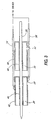
- FIG. 2 One specific embodiment of a dispensing apparatus according to the invention is illustrated in cross section in Figure 2.
- This embodiment comprises a substantially cylindrical capillary 20 made of any number of suitable materials such as quartz or glass.
- the capillary 20 has a tapered end 22 which terminates in an opening 24 which forms the nozzle from which droplets of fluid 26 are dispensed.
- the capillary 20 Surrounding the capillary 20 are two cylindrical piezoelectric actuators 28, 30. One of these actuators 28 is positioned closer to the opening 24 than the other actuator 30.
- the lower actuator 28 may be actuated so as to compress the region of the capillary 20 inside the lower actuator 28. When this occurs, pressure waves force fluid both downward toward the nozzle 24 in the direction of the arrow 32 and upward away from the nozzle 24 and toward the second actuator 30.
- the upper actuator 30 may also be actuated, producing pressure waves which force fluid downward toward the first actuator 28 in the direction of arrow 36 as well as upward out of the second actuator 30 in the direction of arrow 38.
- both actuators 28 and 30 The net effect of the actuation of both actuators 28 and 30 is that the fluid response to the first actuator 28 which is directed upward and away from the nozzle is damped by the presence of the downwardly directed fluid response produced by the second actuator 30. This isolates the lower portion of the capillary 20, prevents significant fluid flow away from the nozzle, and allows the lower actuator 28 to efficiently produce a pressure pulse in the region of the nozzle 24 which can overcome the surface tension of the fluid and eject a droplet 26.
- a constriction may be designed to function to isolate the lower region of the capillary to enhance the efficiency of droplet ejection, but inhibits the ability to remove trapped particulates from the system. Also, the constriction adds to the cost of manufacturing the capillary.
- the "virtual constriction" produced by the second actuator 30 improves dispensing efficiency so that both actuators 28, 30 can be moved farther away from the nozzle 24 and still controllably eject fluid droplets. Moving the actuators further from the nozzle is advantageous because the capillary 20 may extend further down into sample wells during aspiration and fluid dispensing.
- the capillary 20 comprises a quartz tube having an approximately 1 mm outer diameter and an approximately 0.82 mm inner diameter, tapering down to a nozzle with a diameter of approximately 70 microns.
- the actuators 28, 30 comprise approximately 12 mm long cylindrical shells of piezoelectric material such as lead-zirconium-titanate (PZT) having an approximately 1.14 mm inner diameter and a 2.13 mm outer diameter. These dimensions may, of course, vary widely depending on the desired drop volumes.
- the actuators may be mounted on the capillary 20 such that the lowest extent of the lower actuator 28 is more than 10 mm away from the nozzle 24.
- the lowest extent of the lower actuator 28 is more than 20 mm away from the nozzle 24, with approximately 16 mm away having been found suitable in one specific embodiment.
- the actuators 28, 30 may be separated by anywhere from 0 to 10 or more mm. In one embodiment, approximately 3 mm has been found suitable. They may be held in place on the capillary 20 with a small amount of epoxy or other suitable adhesive.
- cylindrical piezoelectric actuators may be provided with two electrodes, one on the inner surface, and one on the outer surface.
- the material is polarized radially such that the application of a voltage of the correct polarity produces a radial expansion of the material. This expansion may be used to compress a fluid filled capillary such as is illustrated in Figure 2.
- Figure 3 another cross section is set forth, again showing the piezoelectric actuators 28, 30 which surround the capillary 20.
- the actuators 28, 30 are each provided with an outer electrode 42, 44 respectively and an inner electrode 46, 48 respectively.
- the electrodes may advantageously comprise a nickel plating.
- the actuators 28, 30 are connected to a driver circuit in parallel.
- a first wire 54 is soldered to the outer electrode 42 of the first actuator 28 and the outer electrode 44 of the second actuator 30.
- a second wire 56 is soldered to the inner electrode 46 of the first actuator 28 and the inner electrode 48 of the second actuator 30.
- the solder connections to the inner electrode may advantageously be made to the outer portions 50, 52 of the inner electrodes 46, 48.
- the wires 54, 56 are connected to a driver circuit which applies a voltage pulse to the electrodes to compress the capillary 20 and eject the droplets as described above in conjunction with Figure 2.
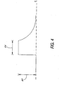
- FIG 4 One embodiment of a voltage waveform which has been found suitable for use with the dispensing device of Figures 2 and 3 is illustrated in Figure 4.
- the pulse shown is applied such that the positive electrode is on the inner surface of the actuators 28, 30, and the ground electrode is on the outer surface of the actuators 28, 30.
- the height 62 of the waveform may be approximately 60 to 150 V with a rise time of about 70 microseconds or less. In general, with a faster rise time, the height 62 of the pulse may be reduced while still producing acceptable droplet formation.
- the duration 64 of the pulse may be from 20 or 30 microseconds up to one millisecond or more. 500 microseconds has been found suitable in one specific embodiment.
- the pulse is preferably ramped downward somewhat slowly from its peak value to help eliminate multiple droplet ejection with a single pulse.
- the voltage drops approximately exponentially to essentially zero in approximately 1 or more milliseconds, with approximately 2 milliseconds having been found suitable in one embodiment. This decay can also be significantly shorter than 1 millisecond while retaining the desired effect.
- each dispensing device can be separately calibrate such that a known volume of fluid is dispensed with each pulse for each dispensing device produced. This may be done by measuring drop volume as a function of pulse height 62, and subsequently driving the device during use with a pulse having a height determined to produce the selected drop volume.
- nanoliter dispensers as described herein can dispense less than approximately 500 nanoliters, more preferably less than approximately 100 nanoliters, and most preferably less than approximately 25 nanoliters.
- minimal volumes dispensed are 5 nanoliters, 500 picoliters, 100 picoliters, 10 picoliters. It is understood that dispensers capable of dispensing such minimal volumes are also capable of dispensing greater volumes.
- the volume dispensed with each pulse will be largely dependent on the pulse height, capillary size, and actuator position. Maximum volumes dispensed are about 10.0 microliters, 1.0 microliters, and 200 nanoliters.
- dispensed volume will typically range from approximately 50 to 400 picoliters.
- Duty cycle may range from 10 pulses per second to 1000 or more pulses per second, depending on the driving pulse width illustrated in Figure 4. In one specific embodiment, 100 droplet dispenses per second is utilized.
- Different pulse shapes may also be used for the different actuators.
- configurations having three or more simultaneously driven actuators may be utilized.
- the fluid dispensing apparatus described with reference to Figures 2 through 3 finds especially advantageous application to high throughput chemical screening apparatus.
- An example of such an application is presented in Figure 5.
- the dispensing apparatus described above may advantageously be incorporated into a sample distribution module in a chemical screening apparatus that can dispense or aspirate large numbers of solutions, usually small volume solutions.
- the sample distribution module will hold large numbers of different stock solutions of chemicals dissolved in aqueous or non-aqueous solvents (e.g., water or dimethylsulfoxide (DMSO)) in addressable chemical wells.
- aqueous or non-aqueous solvents e.g., water or dimethylsulfoxide (DMSO)
- the sample distribution module To facilitate the rapid transfer of these stock solutions, it is desirable for the sample distribution module to aspirate a stock solution from an addressable well and dispense all or a portion of that solution into an addressable sample well or another addressable well.
- This sequence of events can be progammably controlled to ensure that the stock solution is aspirated from a pre-selected addressable chemical well and is dispensed into a pre-selected addressable sample well.
- a chemical screening system with these features is described in copending and co-owned PCT Patent Application No. PCT/US98/09526, filed May 14, 1998 and entitled “Systems and Methods for Rapidly Identifying Useful Chemicals in Liquid Samples" by Stylli et al.
- This screening system may advantageously incorporate the droplet dispensing apparatus described herein.
- the system may comprise a plurality of nanoliter dispensers that can individually dispense a predetermined volume.
- dispensers are arranged in two-dimension array to handle plates of different well densities (e.g., 96, 384, 864 and 3,456).
- a 96 dispenser array 70 is illustrated, shown as 8 sets of 12 dispensers, with each set being designated by a letter A through H.
- the dispensers are coupled to a set of feed lines 71. This coupling may be performed in any number of ways well known or devisable by those of skill in the art.
- the portion of the dispenser comprising the actuators and wiring illustrated in Figure 3 is placed in a hollow plastic casing which contains integral terminals for the wires 54, 56, and an integral stainless steel sleeve which has one end that slides snugly over the end of the capillary 20 opposite the nozzle and has another end that extends out of the plastic casing.
- the case is filled with epoxy potting and cured to secure solder joints between the wires and the terminals, and to seal the coupling between the quartz capillary and the stainless steel tube.
- the feed lines 71 may then be secured over the stainless steel tubes to provide a sealed fluid coupling between each-dispenser and a source of solvent.
- the terminals provided with the plastic casing may be connected to a driver circuit provided as part of the screening so as to provide electrical actuation to the piezoelectric elements inside.
- the dispensers receive solvent such as water or DMSO from a vented reservoir 72.
- the vented reservoir includes a liquid level sensor 74.
- the height of the solvent in the reservoir 72 is maintained at a level of approximately 12 to 25 mm below the level of the nozzles of the dispensers in the array 70. This maintains a slight negative pressure in the capillary, and results in an advantageous slightly inwardly directed meniscus in the solvent at the nozzle of each dispenser.
- the fluid level in the vented reservoir 72 is maintained by periodic refilling from a large solvent reservoir 76 which is pressurized by, for example, a source of compressed air 78 regulated to 5 psi. If the level sensor 74 senses too low a level of solvent in the vented reservoir 72, a valve 80 will route a portion of the pressurized solvent to the vented reservoir 72.
- Each dispenser in a set of 12 is connected via its associated feed line 71 to a port on a commercially available dispenser valve 82.
- This valve 82 includes a selected outlet 83 and a common outlet 84.
- the valve 82 is configured to provide a fluid coupling between the selected outlet 83 and a user selected port, while connecting all other ports to the common outlet 84.
- port 85 is "selected", and the remainder are connected to the "common”.
- the common outlet 84 of the dispenser valve 82 is coupled to the vented solvent reservoir 72 through a second valve 86.
- the 96 dispensers in the array 70 are fed from 8 separate 16 port dispenser valves, with each dispenser valve coupled to 12 dispensers. Ports 13-16 of the dispenser valves 82 in this embodiment are plugged off.
- each of the 8 dispenser valves is coupled to one of the ports of the 10 port second valve 86.
- the selected outlet of each of the eight dispenser valves is connected to a pressure sensor 87 and to respective negative pressure devices 88.
- the eight negative pressure devices may advantageously comprise syringe pumps.
- the apparatus preferably will both aspirate reagent up into the capillaries, and dispense reagent from the capillaries.
- Aspiration of 96 samples may be performed by first selecting port 1 with each dispenser valve 82. With the dispenser tips placed in the desired sample wells, a volume of fluid is drawn into the eight capillaries connected to a port 1 of each dispenser valve using the eight syringe pumps 88. Each syringe pump 88 outlet is then switched toward a waste container 90, and the solvent taken up into the syringe pumps 88 during aspiration is deposited there.
- port 2 is selected with each dispenser valve 82. With the dispenser tips still in the desired sample wells, a volume of fluid is drawn into the next eight capillaries using the syringe pumps 88, and the solvent taken up by the syringe pumps 88 during aspiration is expelled into a waste container 90. This process is repeated for ports 3-12 of the dispenser valves.
- the dispenser valves 82 are set to select port 13. This connects all 12 ports 1-12 to the vented reservoir 72. With the pressure in the capillaries thus equilibrated to the pressure in the vented reservoir 72, the actuators are pulsed as described above, and 96 volumes of fluid are simultaneously dispensed.
- a forward flush process may be performed by sealing and pressurizing the vented reservoir 72. Pressurization may be performed by venting the solvent container 72 through a valve 92 which is coupled to both the ambient atmosphere and to the 5 psi compressed air source 78. During this forward flush procedure, if the all of the dispenser valves 82 are configured to select port 13, all 96 dispensers will be coupled to the previously vented (but now pressurized) solvent reservoir 72.
- a reverse flush process may be performed by repeating the aspiration technique described above a desired number of times.
Abstract
Description
- The invention pertains to the controlled dispensing of small volumes of fluid. The invention has particularly advantageous application to automated and integrated systems and methods for rapidly identifying chemicals with biological activity in liquid samples, particularly automated screening of low volume samples for new medicines, agrochemicals, or cosmetics
- The dispensing of small volumes of fluids is an important aspect of several different technologies, from various printing techniques to chemical screening apparatus for drug discovery. Thus, systems and methods for controllably and accurately dispensing liquid, especially small liquid samples, can benefit a number of different fields. The agrochemical, pharmaceutical, and cosmetic fields all have applications where large numbers of liquid samples containing chemicals are processed. In some instances, the processing of liquid samples, such as in pharmaceutical arts, which usually demands complicated liquid processing for drug discovery, can obtain throughput rates of approximately 10,000 samples per day or greater.
- A wide variety of designs for dispensers have been utilized. In some applications, a piezoelectric actuator is coupled to a fluid chamber that contains a nozzle for droplet ejection. When the piezoelectric material is actuated, a droplet of fluid is ejected through the nozzle. Such a system is illustrated in U.S. Patent No. 4,877,745 to Hayes, et al. Dispensers with several piezoelectric actuators are also known (US-A-4523199, US-A-4672398).
- This method of droplet ejection includes several complications, however, such as the production of undesired fluid responses to actuation which interfere with efficient droplet ejection. One possible method of damping undesired fluid responses in a piezoelectrically compressed fluid chamber involves placing selected materials inside or around the rearward portion of the fluid chamber that cushion or passively dampen the pressure wave in the chamber. Some of these techniques are described, for example, in U.S. Patent Nos. 3,832,579 to Arndt, 4,233,610 to Fischbeck et al., and 4,528,579 to Brescia. However, these passive systems are relatively expensive to implement, and may need significant alteration depending on the physical properties of the fluid being dispensed.
- Another proposed solution to undesired fluid responses, illustrated in U.S. Patent No. 4,418,354 to Perduijn involves placing a fluid flow restriction in a portion of the fluid chamber rearward from the nozzle. A dispensing apparatus with a similar functional constriction is commercially available from Packard Instrument Company of Meridan, Connecticut as an accessory to the MultiProbe 104. The presence of the restriction, however, produces additional difficulties, such as inhibiting removal of particulate matter that may become inadvertently introduced into the fluid chamber. Once a particle gets inside the fluid chamber, it may become trapped between the small diameter nozzle and small diameter restriction, thereby clogging the device and interfering with the proper operation of the dispenser.
- A need therefore exists for efficient droplet dispensing devices which do not suffer from the above mentioned drawbacks.
- The invention is directed to an apparatus for fluid dispensing as defined in
claim 1. In one embodiment a fluid dispensing apparatus includes a capillary having an opening for droplet dispensing, a first actuator mechanically coupled to and configured to alter the volume of the fluid chamber, and a second actuator mechanically coupled to and configured to alter the volume the fluid chamber. The apparatus may also include a driver connected to actuate the first and second actuators so as to alter the volume of the fluid chamber, whereby a fluid response produced by the first actuator is damped by the second actuator. The actuators may comprise piezoelectric actuators which are actuated substantially simultaneously. A method of dispensing a fluid is also provided. -
- FIG. 1 is a block diagram of a dispensing device.
- FIG. 2 is a cross section of a cylindrical droplet dispensing device in accordance with the invention.
- FIG. 3 is a cross section of a cylindrical drop dispensing device illustrating one embodiment of the electrical connection between piezoelectric actuators and a driver circuit.
- FIG. 4 is a graphical illustration of one embodiment of a voltage waveform suitable for actuating the piezoelectric actuators of Figures 2 and 3.
- FIG. 5 is a block diagram illustrating a fluid delivery system into which the dispensers of Figures 2 and 3 may be advantageously incorporated.
- Embodiments of the invention will now be described with reference to the accompanying Figures, wherein like numerals refer to like elements throughout. The terminology used in the description presented herein is not intended to be interpreted in any limited or restrictive manner, simply because it is being utilized in conjunction with a detailed description of certain specific embodiments of the invention.
- Referring now to Figure 1, a block diagram representation of a droplet dispensing device is shown. The device includes a
fluid chamber 10. Thisfluid chamber 10 includes an opening (not shown in Figure 1) from which fluid is ejected. The fluid chamber will also generally be connected to a large volume source of solvent (not shown in Figure 1) for replenishing expelled fluid. The dispensing device may eject fluid received form this fluid source. In many other instances, however, the fluid ejected from the nozzle will have previously been aspirated into thechamber 10 through the nozzle rather than received from a large volume source. - Droplets are dispensed from the fluid chamber by altering the fluid chamber volume with actuators which are mechanically coupled to the fluid chamber. This may be done by compressing the chamber so as to squeeze out a droplet, and then letting the chamber expand to its original volume. This may also be done by first expanding the chamber so as to draw additional fluid from the large volume source, and then letting the chamber contract to its original volume so as to squeeze out a droplet.
- In many prior art designs, when the fluid chamber is compressed by actuation, the fluid will not only be forced in a forward direction toward the nozzle, but will also be forced backward away from the nozzle at the same time. This rearwardly directed fluid response hinders the capacity of the nozzle directed fluid response to overcome fluid surface tension at the nozzle. Droplet ejection can be therefore inefficient and may even be impossible.
- In the embodiment of Figure 1, the
fluid chamber 10 is coupled to two actuators, referred to as a dispensingactuator 12, and a damping actuator 16 (as represented schematically by the arrows pointing toward the fluid chamber 10). These twoactuators actuator 12 may be more closely associated with the ejection nozzle of the fluid chamber than the dampingactuator 16, and may thus be more directly associated with droplet ejection. In these embodiments, thedamping actuator 16 has the principal function of damping a fluid response to actuation of the dispensingactuator 12. The fluid response damped by the dampingactuator 16 may advantageously be a response that otherwise reduces the efficiency of droplet ejection. It will be appreciated by those of skill in the art, however, that the labels "dispensing" and "damping" for the two actuators are not mutually exclusive. In particular, it will be appreciated that bothactuators - It will be appreciated by those in the art that a wide variety of actuators and methods of coupling actuators to fluid chambers have been devised and are known in the art. In most instances, the actuators used are made of a piezoelectric material which expands, bends, leans, or otherwise deforms in response to an applied voltage. In some cases, the actuators are flexing planar membranes. In others, the actuator undergoes a piston-like motion to eject a droplet. In still other cases, the walls of the fluid chamber are themselves made of a piezoelectric material. It will be appreciated that each
individual actuator fluid chamber 10 may be implemented using any actuation technique which suits the desired dispensing application. - One specific embodiment of a dispensing apparatus according to the invention is illustrated in cross section in Figure 2. This embodiment comprises a substantially
cylindrical capillary 20 made of any number of suitable materials such as quartz or glass. Thecapillary 20 has atapered end 22 which terminates in anopening 24 which forms the nozzle from which droplets offluid 26 are dispensed. - Surrounding the capillary 20 are two cylindrical
piezoelectric actuators actuators 28 is positioned closer to theopening 24 than theother actuator 30. In operation, thelower actuator 28 may be actuated so as to compress the region of the capillary 20 inside thelower actuator 28. When this occurs, pressure waves force fluid both downward toward thenozzle 24 in the direction of thearrow 32 and upward away from thenozzle 24 and toward thesecond actuator 30. Theupper actuator 30 may also be actuated, producing pressure waves which force fluid downward toward thefirst actuator 28 in the direction ofarrow 36 as well as upward out of thesecond actuator 30 in the direction ofarrow 38. - The net effect of the actuation of both
actuators first actuator 28 which is directed upward and away from the nozzle is damped by the presence of the downwardly directed fluid response produced by thesecond actuator 30. This isolates the lower portion of the capillary 20, prevents significant fluid flow away from the nozzle, and allows thelower actuator 28 to efficiently produce a pressure pulse in the region of thenozzle 24 which can overcome the surface tension of the fluid and eject adroplet 26. - Several advantages to the designs described herein over the prior art are apparent. First, no constriction needs to be present in the capillary 20 in the region upward from the
nozzle 24. As described above, a constriction may be designed to function to isolate the lower region of the capillary to enhance the efficiency of droplet ejection, but inhibits the ability to remove trapped particulates from the system. Also, the constriction adds to the cost of manufacturing the capillary. In addition, the "virtual constriction" produced by thesecond actuator 30 improves dispensing efficiency so that bothactuators nozzle 24 and still controllably eject fluid droplets. Moving the actuators further from the nozzle is advantageous because the capillary 20 may extend further down into sample wells during aspiration and fluid dispensing. - In one specific embodiment, the capillary 20 comprises a quartz tube having an approximately 1 mm outer diameter and an approximately 0.82 mm inner diameter, tapering down to a nozzle with a diameter of approximately 70 microns. The
actuators lower actuator 28 is more than 10 mm away from thenozzle 24. In some embodiments, the lowest extent of thelower actuator 28 is more than 20 mm away from thenozzle 24, with approximately 16 mm away having been found suitable in one specific embodiment. Theactuators - Turning now to Figures 3 and 4, actuation of the
piezoelectric actuators piezoelectric actuators - The
actuators outer electrode 42, 44 respectively and aninner electrode inner electrodes electrode portions actuators inner electrodes actuators electrodes - It has been found that simultaneous actuation of both
actuators actuators first wire 54 is soldered to the outer electrode 42 of thefirst actuator 28 and theouter electrode 44 of thesecond actuator 30. In addition, asecond wire 56 is soldered to theinner electrode 46 of thefirst actuator 28 and theinner electrode 48 of thesecond actuator 30. The solder connections to the inner electrode may advantageously be made to theouter portions inner electrodes wires - One embodiment of a voltage waveform which has been found suitable for use with the dispensing device of Figures 2 and 3 is illustrated in Figure 4. The pulse shown is applied such that the positive electrode is on the inner surface of the
actuators actuators height 62 of the waveform may be approximately 60 to 150 V with a rise time of about 70 microseconds or less. In general, with a faster rise time, theheight 62 of the pulse may be reduced while still producing acceptable droplet formation. Theduration 64 of the pulse may be from 20 or 30 microseconds up to one millisecond or more. 500 microseconds has been found suitable in one specific embodiment. The pulse is preferably ramped downward somewhat slowly from its peak value to help eliminate multiple droplet ejection with a single pulse. In one embodiment, the voltage drops approximately exponentially to essentially zero in approximately 1 or more milliseconds, with approximately 2 milliseconds having been found suitable in one embodiment. This decay can also be significantly shorter than 1 millisecond while retaining the desired effect. - Because material and manufacturing variations will affect droplet size and efficiency of ejection, it can be advantageous to separately calibrate each dispensing device such that a known volume of fluid is dispensed with each pulse for each dispensing device produced. This may be done by measuring drop volume as a function of
pulse height 62, and subsequently driving the device during use with a pulse having a height determined to produce the selected drop volume. - In reagent dispensing environments, for example, it is usually advantageous to dispense less than approximately 2,000 nanoliters of liquid with each pulse. Preferably, nanoliter dispensers as described herein can dispense less than approximately 500 nanoliters, more preferably less than approximately 100 nanoliters, and most preferably less than approximately 25 nanoliters. Preferred, minimal volumes dispensed are 5 nanoliters, 500 picoliters, 100 picoliters, 10 picoliters. It is understood that dispensers capable of dispensing such minimal volumes are also capable of dispensing greater volumes. The volume dispensed with each pulse will be largely dependent on the pulse height, capillary size, and actuator position. Maximum volumes dispensed are about 10.0 microliters, 1.0 microliters, and 200 nanoliters. In the specific 1 mm outer diameter capillary embodiment described with reference to Figures 2, 3, and 4, dispensed volume will typically range from approximately 50 to 400 picoliters. Duty cycle may range from 10 pulses per second to 1000 or more pulses per second, depending on the driving pulse width illustrated in Figure 4. In one specific embodiment, 100 droplet dispenses per second is utilized.
- Different pulse shapes may also be used for the different actuators. Furthermore, configurations having three or more simultaneously driven actuators may be utilized.
- As mentioned above, the fluid dispensing apparatus described with reference to Figures 2 through 3 finds especially advantageous application to high throughput chemical screening apparatus. An example of such an application is presented in Figure 5. The dispensing apparatus described above may advantageously be incorporated into a sample distribution module in a chemical screening apparatus that can dispense or aspirate large numbers of solutions, usually small volume solutions. In many instances, the sample distribution module will hold large numbers of different stock solutions of chemicals dissolved in aqueous or non-aqueous solvents (e.g., water or dimethylsulfoxide (DMSO)) in addressable chemical wells. To facilitate the rapid transfer of these stock solutions, it is desirable for the sample distribution module to aspirate a stock solution from an addressable well and dispense all or a portion of that solution into an addressable sample well or another addressable well. This sequence of events can be progammably controlled to ensure that the stock solution is aspirated from a pre-selected addressable chemical well and is dispensed into a pre-selected addressable sample well. A chemical screening system with these features is described in copending and co-owned PCT Patent Application No. PCT/US98/09526, filed May 14, 1998 and entitled "Systems and Methods for Rapidly Identifying Useful Chemicals in Liquid Samples" by Stylli et al. This screening system may advantageously incorporate the droplet dispensing apparatus described herein.
- In one embodiment, the system may comprise a plurality of nanoliter dispensers that can individually dispense a predetermined volume. Typically, dispensers are arranged in two-dimension array to handle plates of different well densities (e.g., 96, 384, 864 and 3,456). In Figure 5, a 96
dispenser array 70 is illustrated, shown as 8 sets of 12 dispensers, with each set being designated by a letter A through H. The dispensers are coupled to a set of feed lines 71. This coupling may be performed in any number of ways well known or devisable by those of skill in the art. In one embodiment, the portion of the dispenser comprising the actuators and wiring illustrated in Figure 3 is placed in a hollow plastic casing which contains integral terminals for thewires - The dispensers receive solvent such as water or DMSO from a vented
reservoir 72. The vented reservoir includes aliquid level sensor 74. The height of the solvent in thereservoir 72 is maintained at a level of approximately 12 to 25 mm below the level of the nozzles of the dispensers in thearray 70. This maintains a slight negative pressure in the capillary, and results in an advantageous slightly inwardly directed meniscus in the solvent at the nozzle of each dispenser. - The fluid level in the vented
reservoir 72 is maintained by periodic refilling from a largesolvent reservoir 76 which is pressurized by, for example, a source ofcompressed air 78 regulated to 5 psi. If thelevel sensor 74 senses too low a level of solvent in the ventedreservoir 72, avalve 80 will route a portion of the pressurized solvent to the ventedreservoir 72. - Each dispenser in a set of 12 is connected via its associated
feed line 71 to a port on a commerciallyavailable dispenser valve 82. Thisvalve 82 includes a selectedoutlet 83 and acommon outlet 84. Thevalve 82 is configured to provide a fluid coupling between the selectedoutlet 83 and a user selected port, while connecting all other ports to thecommon outlet 84. In Figure 5,port 85 is "selected", and the remainder are connected to the "common". Thecommon outlet 84 of thedispenser valve 82 is coupled to the ventedsolvent reservoir 72 through a second valve 86. In this embodiment, the 96 dispensers in thearray 70 are fed from 8 separate 16 port dispenser valves, with each dispenser valve coupled to 12 dispensers. Ports 13-16 of thedispenser valves 82 in this embodiment are plugged off. The common outlet of each of the 8 dispenser valves is coupled to one of the ports of the 10 port second valve 86. The selected outlet of each of the eight dispenser valves is connected to apressure sensor 87 and to respectivenegative pressure devices 88. The eight negative pressure devices may advantageously comprise syringe pumps. - As mentioned above, the apparatus preferably will both aspirate reagent up into the capillaries, and dispense reagent from the capillaries. Aspiration of 96 samples may be performed by first selecting
port 1 with eachdispenser valve 82. With the dispenser tips placed in the desired sample wells, a volume of fluid is drawn into the eight capillaries connected to aport 1 of each dispenser valve using the eight syringe pumps 88. Eachsyringe pump 88 outlet is then switched toward awaste container 90, and the solvent taken up into the syringe pumps 88 during aspiration is deposited there. - Next, port 2 is selected with each
dispenser valve 82. With the dispenser tips still in the desired sample wells, a volume of fluid is drawn into the next eight capillaries using the syringe pumps 88, and the solvent taken up by the syringe pumps 88 during aspiration is expelled into awaste container 90. This process is repeated for ports 3-12 of the dispenser valves. - To dispense the 96 aspirated samples, the
dispenser valves 82 are set to select port 13. This connects all 12 ports 1-12 to the ventedreservoir 72. With the pressure in the capillaries thus equilibrated to the pressure in the ventedreservoir 72, the actuators are pulsed as described above, and 96 volumes of fluid are simultaneously dispensed. - A forward flush process may be performed by sealing and pressurizing the vented
reservoir 72. Pressurization may be performed by venting thesolvent container 72 through avalve 92 which is coupled to both the ambient atmosphere and to the 5 psi compressedair source 78. During this forward flush procedure, if the all of thedispenser valves 82 are configured to select port 13, all 96 dispensers will be coupled to the previously vented (but now pressurized)solvent reservoir 72. A reverse flush process may be performed by repeating the aspiration technique described above a desired number of times. - The foregoing description details certain embodiments of the invention. It will be appreciated, however, that no matter how detailed the foregoing appears in text, the invention can be practiced in many ways. As is also stated above, it should be noted that the use of particular terminology when describing certain features or aspects of the invention should not be taken to imply that the terminology is being re-defined herein to be restricted to including any specific characteristics of the features or aspects of the invention with which that terminology is associated. The scope of the invention should therefore be construed in accordance with the appended claims.
Claims (10)
- A piezoelectric fluid aspiration and dispensing device comprising a capillary having an opening in one end for aspirating and dispensing fluid, wherein said capillary is at least partially surrounded by a plurality of cylindrical piezoelectric actuators positioned behind said opening, wherein said plurality of cylindrical piezoelectric actuators are coupled to a driver having drive circuitry for simultaneous actuation of said actuators; an wherein said capillary is unrestricted behind said piezoelectric actuators so as to allow aspirated particulate material to flow away from said opening during a reverse flush cycle.
- The dispensing device of Claim 1, wherein a first cylindrical piezoelectric actuator extends from approximately 16 mm behind said opening to approximately 29 mm behind said opening.
- The dispensing device of Claim 2, wherein a second cylindrical piezoelectric actuator extends from approximately 32 mm behind said opening to approximately 45 mm behind said opening.
- A method of dispensing a volume of fluid comprising:substantially simultaneously actuating a plurality of cylindrical piezoelectric actuators which surround a capillary having an opening in one end for aspirating and dispensing fluid, wherein a plurality of cylindrical piezoelectric actuators are positioned behind said opening, wherein said plurality of cylindrical piezoelectric actuators are coupled to a driver having drive circuitry for simultaneous actuation of said actuators; and wherein said capillary is unrestricted behind said piezoelectric actuators so as to allow aspirated particulate material to flow away from said opening during a reverse flush cycle.
- The method of Claim 4 wherein said capillary is connected to a nozzle.
- The method of Claim 4 wherein said driver is connected to said actuators in parallel.
- A method of making a droplet deposition device comprising:positioning a first cylindrical piezoelectric actuator around a capillary proximate to an ejection nozzle in one end of said capillary for aspirating and dispensing fluid;positioning a second cylindrical piezoelectric actuator around said capillary farther from said ejection nozzle than said first actuator; andconnecting both of said cylindrical piezoelectric actuators to a driver configured to actuate said first and second cylindrical piezoelectric actuators substantially simultaneously.
- The method of Claim 7, further comprising positioning at least one additional actuator so as to substantially surround a glass capillary with actuators.
- The method of Claim 8, wherein said at least one additional actuator is a cylindrical piezoelectric actuator.
- The method of Claim 7, wherein said connecting comprises connecting said actuators in parallel to a voltage source.
Applications Claiming Priority (3)
| Application Number | Priority Date | Filing Date | Title |
|---|---|---|---|
| US09/210,260 US6296811B1 (en) | 1998-12-10 | 1998-12-10 | Fluid dispenser and dispensing methods |
| US210260 | 1998-12-10 | ||
| EP99965225A EP1137489B1 (en) | 1998-12-10 | 1999-12-10 | Fluid dispenser and dispensing methods |
Related Parent Applications (1)
| Application Number | Title | Priority Date | Filing Date |
|---|---|---|---|
| EP99965225A Division EP1137489B1 (en) | 1998-12-10 | 1999-12-10 | Fluid dispenser and dispensing methods |
Publications (3)
| Publication Number | Publication Date |
|---|---|
| EP1316361A2 EP1316361A2 (en) | 2003-06-04 |
| EP1316361A3 EP1316361A3 (en) | 2004-03-31 |
| EP1316361B1 true EP1316361B1 (en) | 2007-02-21 |
Family
ID=22782204
Family Applications (2)
| Application Number | Title | Priority Date | Filing Date |
|---|---|---|---|
| EP99965225A Expired - Lifetime EP1137489B1 (en) | 1998-12-10 | 1999-12-10 | Fluid dispenser and dispensing methods |
| EP03004222A Expired - Lifetime EP1316361B1 (en) | 1998-12-10 | 1999-12-10 | Fluid dispenser and dispensing methods |
Family Applications Before (1)
| Application Number | Title | Priority Date | Filing Date |
|---|---|---|---|
| EP99965225A Expired - Lifetime EP1137489B1 (en) | 1998-12-10 | 1999-12-10 | Fluid dispenser and dispensing methods |
Country Status (11)
| Country | Link |
|---|---|
| US (3) | US6296811B1 (en) |
| EP (2) | EP1137489B1 (en) |
| JP (1) | JP2002531259A (en) |
| AT (2) | ATE244604T1 (en) |
| AU (1) | AU3118900A (en) |
| CA (1) | CA2354555C (en) |
| DE (2) | DE69909511T2 (en) |
| DK (1) | DK1137489T3 (en) |
| ES (2) | ES2201823T3 (en) |
| PT (1) | PT1137489E (en) |
| WO (1) | WO2000033961A1 (en) |
Families Citing this family (67)
| Publication number | Priority date | Publication date | Assignee | Title |
|---|---|---|---|---|
| DE19754000A1 (en) * | 1997-12-05 | 1999-06-17 | Max Planck Gesellschaft | Device and method for the electrically triggered microdrop delivery with a dispensing head |
| GB9906477D0 (en) * | 1999-03-19 | 1999-05-12 | Pyrosequencing Ab | Liquid dispensing apparatus |
| US7214540B2 (en) | 1999-04-06 | 2007-05-08 | Uab Research Foundation | Method for screening crystallization conditions in solution crystal growth |
| US7250305B2 (en) * | 2001-07-30 | 2007-07-31 | Uab Research Foundation | Use of dye to distinguish salt and protein crystals under microcrystallization conditions |
| US7244396B2 (en) | 1999-04-06 | 2007-07-17 | Uab Research Foundation | Method for preparation of microarrays for screening of crystal growth conditions |
| DE10010208C2 (en) * | 2000-02-25 | 2002-02-07 | Inst Physikalische Hochtech Ev | Microdosing device for the defined delivery of small, closed liquid volumes |
| US6709872B1 (en) * | 2000-05-02 | 2004-03-23 | Irm Llc | Method and apparatus for dispensing low nanoliter volumes of liquid while minimizing waste |
| DE10046379A1 (en) * | 2000-09-20 | 2002-03-28 | Zeiss Carl | System for the targeted deformation of optical elements |
| US7135146B2 (en) | 2000-10-11 | 2006-11-14 | Innovadyne Technologies, Inc. | Universal non-contact dispense peripheral apparatus and method for a primary liquid handling device |
| US6852291B1 (en) | 2000-10-11 | 2005-02-08 | Innovadyne Technologies, Inc. | Hybrid valve apparatus and method for fluid handling |
| EP1205247A2 (en) * | 2000-10-16 | 2002-05-15 | Ngk Insulators, Ltd. | Micropipette, dispenser and method for producing biochip |
| DE10052819B4 (en) * | 2000-10-24 | 2004-02-19 | Fraunhofer-Gesellschaft zur Förderung der angewandten Forschung e.V. | Pipette system and pipette array and method for filling a pipette system |
| US20020106812A1 (en) * | 2001-01-26 | 2002-08-08 | Fisher William D. | Fluid drop dispensing |
| US20020106308A1 (en) * | 2001-02-02 | 2002-08-08 | Zweifel Ronald A. | Microdrop dispensing apparatus |
| DE10106605A1 (en) * | 2001-02-13 | 2002-08-22 | Zeiss Carl | System for eliminating or at least damping vibrations |
| WO2002070133A1 (en) * | 2001-03-01 | 2002-09-12 | Peter Wiktor | Piezoelectric pipetting device housing and methods for making and using the same |
| US6480114B2 (en) * | 2001-03-23 | 2002-11-12 | Nordson Corporation | High impedance diagnostic for gun driver and method |
| US7670429B2 (en) | 2001-04-05 | 2010-03-02 | The California Institute Of Technology | High throughput screening of crystallization of materials |
| DE10132530A1 (en) | 2001-07-09 | 2003-01-30 | Evotec Ag | Method for monitoring the functionality of a liquid delivery device and liquid delivery device |
| DE10136387A1 (en) * | 2001-07-26 | 2003-02-13 | Zeiss Carl | Optical objective for semiconductor lithography has optical element with reflective reference surface used for adjustment relative to objective |
| US20030095167A1 (en) * | 2001-11-16 | 2003-05-22 | Jameson Lee Kirby | Apparatus and method to produce topography, unique fluid handling properties and bonding properties on and within substrates |
| DE60317305T2 (en) * | 2002-01-25 | 2008-08-28 | Innovadyne Technologies, Inc., Santa Rosa | CONTACTLESS METHOD FOR DISTRIBUTING LOW LIQUID QUANTITIES |
| US7288228B2 (en) * | 2002-02-12 | 2007-10-30 | Gilson, Inc. | Sample injection system |
| US6782928B2 (en) * | 2002-03-15 | 2004-08-31 | Lg.Philips Lcd Co., Ltd. | Liquid crystal dispensing apparatus having confirming function for remaining amount of liquid crystal and method for measuring the same |
| DE10219514A1 (en) | 2002-04-30 | 2003-11-13 | Zeiss Carl Smt Ag | Lighting system, especially for EUV lithography |
| EP1364710B1 (en) * | 2002-05-13 | 2009-10-07 | Becton, Dickinson and Company | Self-aliquoting sample storage plate |
| US7452712B2 (en) | 2002-07-30 | 2008-11-18 | Applied Biosystems Inc. | Sample block apparatus and method of maintaining a microcard on a sample block |
| US6874699B2 (en) * | 2002-10-15 | 2005-04-05 | Wisconsin Alumni Research Foundation | Methods and apparata for precisely dispensing microvolumes of fluids |
| JP4253178B2 (en) * | 2002-12-02 | 2009-04-08 | アークレイ株式会社 | Method for manufacturing analytical tool |
| DE502004009503D1 (en) * | 2003-01-23 | 2009-07-02 | Evotec Ag | PROCESS FOR FILLING SAMPLE CARRIERS |
| WO2004099059A2 (en) * | 2003-04-30 | 2004-11-18 | Aurora Discovery, Inc. | Method and system for precise dispensation of a liquid |
| WO2005007896A1 (en) * | 2003-07-18 | 2005-01-27 | Vertex Pharmaceuticals Incorporated | Methods for identifying modulators of quorum-sensing signaling in bacteria |
| US7407630B2 (en) * | 2003-09-19 | 2008-08-05 | Applera Corporation | High density plate filler |
| US7998435B2 (en) * | 2003-09-19 | 2011-08-16 | Life Technologies Corporation | High density plate filler |
| US20050221358A1 (en) * | 2003-09-19 | 2005-10-06 | Carrillo Albert L | Pressure chamber clamp mechanism |
| US20070014694A1 (en) * | 2003-09-19 | 2007-01-18 | Beard Nigel P | High density plate filler |
| US20050226782A1 (en) * | 2003-09-19 | 2005-10-13 | Reed Mark T | High density plate filler |
| US20050232821A1 (en) * | 2003-09-19 | 2005-10-20 | Carrillo Albert L | High density plate filler |
| US20050226779A1 (en) * | 2003-09-19 | 2005-10-13 | Oldham Mark F | Vacuum assist for a microplate |
| US20050226771A1 (en) * | 2003-09-19 | 2005-10-13 | Lehto Dennis A | High speed microplate transfer |
| US20060233671A1 (en) * | 2003-09-19 | 2006-10-19 | Beard Nigel P | High density plate filler |
| US20060272738A1 (en) * | 2003-09-19 | 2006-12-07 | Gary Lim | High density plate filler |
| US20060233673A1 (en) * | 2003-09-19 | 2006-10-19 | Beard Nigel P | High density plate filler |
| US20050233472A1 (en) * | 2003-09-19 | 2005-10-20 | Kao H P | Spotting high density plate using a banded format |
| US20050220675A1 (en) * | 2003-09-19 | 2005-10-06 | Reed Mark T | High density plate filler |
| US8277760B2 (en) * | 2003-09-19 | 2012-10-02 | Applied Biosystems, Llc | High density plate filler |
| US20070015289A1 (en) * | 2003-09-19 | 2007-01-18 | Kao H P | Dispenser array spotting |
| CA2547728A1 (en) * | 2003-12-04 | 2005-06-23 | Jim Yuchen Chang | Material conveying systems, computer program products, and methods |
| US7265917B2 (en) * | 2003-12-23 | 2007-09-04 | Carl Zeiss Smt Ag | Replacement apparatus for an optical element |
| EP1604741A1 (en) | 2004-05-14 | 2005-12-14 | F. Hoffmann-La Roche Ag | Method and apparatus for dispensing a liquid with a pipetting needle |
| EP1614469B1 (en) * | 2004-05-14 | 2007-09-19 | F. Hoffmann-La Roche Ag | Method and apparatus for dispensing a liquid with a pipetting needle |
| FR2879482B1 (en) * | 2004-12-20 | 2007-03-30 | Oreal | DEVICE FOR SPRAYING A PRODUCT, IN PARTICULAR A FRAGRANCE |
| AU2005320910B9 (en) * | 2004-12-30 | 2011-09-01 | Safend Ltd | Method and system for securely identifying computer storage devices |
| DE102005025640A1 (en) * | 2005-06-03 | 2006-12-07 | Scienion Ag | Microdispenser and associated operating method |
| EP2098588B1 (en) * | 2006-11-22 | 2013-01-02 | Altair Corporation | Pipette core member, pipette, and pipette device |
| CA2671978A1 (en) * | 2006-12-18 | 2008-06-26 | Avon Products, Inc. | Self-contained voltage generating systems |
| FR2910253B1 (en) * | 2006-12-20 | 2010-03-12 | Oreal | METHOD FOR DISPENSING A PRODUCT SPRAYED BY A PIEZOELECTRIC SPRAY SYSTEM AND A SPRAY SYSTEM FOR IMPLEMENTING SUCH A METHOD |
| FR2910254B1 (en) * | 2006-12-20 | 2009-04-17 | Oreal | PIEZOELECTRIC SPRAY SYSTEM AND CORRESPONDING REFILL |
| DE102008000967B4 (en) | 2008-04-03 | 2015-04-09 | Carl Zeiss Smt Gmbh | Projection exposure machine for EUV microlithography |
| WO2010063290A2 (en) | 2008-12-05 | 2010-06-10 | Fluisense Aps | A body fluid sampling device and a method thereof |
| US9068566B2 (en) * | 2011-01-21 | 2015-06-30 | Biodot, Inc. | Piezoelectric dispenser with a longitudinal transducer and replaceable capillary tube |
| US20130206857A1 (en) * | 2011-01-21 | 2013-08-15 | Biodot, Inc. | Piezoelectric dispenser with a longitudinal transducer and replaceable capillary tube |
| US10684303B2 (en) * | 2011-07-22 | 2020-06-16 | Vanrx Pharmasystems Inc. | Method for protecting and unprotecting the fluid path in a controlled environment enclosure |
| ITMI20121803A1 (en) * | 2012-10-24 | 2014-04-25 | Altergon Sa | METHOD AND MEASUREMENT AND CONTROL DEVICE FOR THE DOSAGE OF SMALL QUANTITIES OF FLUID BY MEANS OF NEEDLE RESONANT, AND NEEDLE RESONANT SUITABLE FOR THE PURPOSE |
| JP7154192B2 (en) | 2019-06-27 | 2022-10-17 | 京セラ株式会社 | pipette |
| CN110787851B (en) * | 2019-10-25 | 2020-12-04 | 浙江大学 | Multi-channel liquid drop quantitative measuring device and method based on pressure driving |
| TW202315462A (en) * | 2021-06-10 | 2023-04-01 | 荷蘭商Asml荷蘭公司 | Target supply apparatus |
Family Cites Families (41)
| Publication number | Priority date | Publication date | Assignee | Title |
|---|---|---|---|---|
| US3946398A (en) * | 1970-06-29 | 1976-03-23 | Silonics, Inc. | Method and apparatus for recording with writing fluids and drop projection means therefor |
| US3683212A (en) * | 1970-09-09 | 1972-08-08 | Clevite Corp | Pulsed droplet ejecting system |
| US3832579A (en) | 1973-02-07 | 1974-08-27 | Gould Inc | Pulsed droplet ejecting system |
| US4032929A (en) * | 1975-10-28 | 1977-06-28 | Xerox Corporation | High density linear array ink jet assembly |
| DE2555749C3 (en) * | 1975-12-11 | 1980-09-11 | Olympia Werke Ag, 2940 Wilhelmshaven | Device for damping the backflow of the ink in the nozzle of an ink jet head |
| DE2756134A1 (en) * | 1977-12-16 | 1979-06-21 | Ibm Deutschland | PIEZOELECTRICALLY CONTROLLED DRIVE ARRANGEMENT FOR THE GENERATION OF HIGH SHOCK SPEEDS AND / OR CONTROLLED STROKE |
| JPS592617B2 (en) * | 1977-12-22 | 1984-01-19 | 株式会社リコー | ink jetting device |
| US4308546A (en) * | 1978-03-15 | 1981-12-29 | Gould Inc. | Ink jet tip assembly |
| JPS54159228A (en) * | 1978-06-07 | 1979-12-15 | Ricoh Co Ltd | Method and apparatus for ink jet recording |
| JPH0234780B2 (en) | 1978-11-13 | 1990-08-06 | Canon Kk | KIROKUHOHO |
| US4199770A (en) * | 1978-12-04 | 1980-04-22 | Xerox Corporation | Coincidence gate ink jet with increased operating pressure window |
| US4233610A (en) | 1979-06-18 | 1980-11-11 | Xerox Corporation | Hydrodynamically damped pressure pulse droplet ejector |
| JPS5729463A (en) | 1980-07-30 | 1982-02-17 | Nec Corp | Liquid jet head |
| US4354197A (en) * | 1980-10-03 | 1982-10-12 | Ncr Corporation | Ink jet printer drive means |
| DE3170016D1 (en) * | 1980-10-15 | 1985-05-23 | Hitachi Ltd | Ink jet printing apparatus |
| US4395719A (en) * | 1981-01-05 | 1983-07-26 | Exxon Research And Engineering Co. | Ink jet apparatus with a flexible piezoelectric member and method of operating same |
| JPS57144767A (en) | 1981-03-04 | 1982-09-07 | Toshiba Corp | Pressure pulse type ink jet recording device |
| NL8102227A (en) | 1981-05-07 | 1982-12-01 | Philips Nv | METHOD FOR MANUFACTURING JET PIPES AND INK PRINT WITH A JET PIPE MANUFACTURED BY THAT PROCESS. |
| US4418356A (en) * | 1981-09-23 | 1983-11-29 | Ncr Corporation | Ink jet print head |
| US4520374A (en) * | 1981-10-07 | 1985-05-28 | Epson Corporation | Ink jet printing apparatus |
| US4499479A (en) * | 1982-08-30 | 1985-02-12 | International Business Machines Corporation | Gray scale printing with ink jet drop-on demand printing head |
| US4523199A (en) * | 1982-09-29 | 1985-06-11 | Exxon Research & Engineering Co. | High stability demand ink jet apparatus and method of operating same |
| IT1157118B (en) | 1982-12-03 | 1987-02-11 | Olivetti & Co Spa | INK JET PRINTER DEVICE |
| DE3341401A1 (en) * | 1983-11-15 | 1985-05-23 | Siemens AG, 1000 Berlin und 8000 München | METHOD AND CONVERTER FOR INCREASING RESOLUTION IN AN INK MOSAIC WRITER |
| JPS61106259A (en) * | 1984-10-31 | 1986-05-24 | Hitachi Ltd | Ink droplet jet discharging device |
| US4550325A (en) * | 1984-12-26 | 1985-10-29 | Polaroid Corporation | Drop dispensing device |
| US4605939A (en) * | 1985-08-30 | 1986-08-12 | Pitney Bowes Inc. | Ink jet array |
| DE3645017C2 (en) | 1985-09-06 | 1990-07-12 | Fuji Electric Co., Ltd., Kawasaki, Kanagawa, Jp | |
| US4822250A (en) * | 1986-03-24 | 1989-04-18 | Hitachi, Ltd. | Apparatus for transferring small amount of fluid |
| US4877745A (en) | 1986-11-17 | 1989-10-31 | Abbott Laboratories | Apparatus and process for reagent fluid dispensing and printing |
| US4992808A (en) | 1987-01-10 | 1991-02-12 | Xaar Limited | Multi-channel array, pulsed droplet deposition apparatus |
| US4887100A (en) | 1987-01-10 | 1989-12-12 | Am International, Inc. | Droplet deposition apparatus |
| JPS63283739A (en) * | 1987-05-14 | 1988-11-21 | Agency Of Ind Science & Technol | Small amount takeoff device for fine powder-viscous fluid or the like |
| JPH02293040A (en) * | 1989-05-08 | 1990-12-04 | Misuzu Erii:Kk | Quantitatively force-feeding method for fluid |
| US5432540A (en) | 1992-02-25 | 1995-07-11 | Citizen Watch Co., Ltd. | Ink jet head |
| JPH06218917A (en) * | 1993-01-22 | 1994-08-09 | Sharp Corp | Ink jet head |
| US5958342A (en) | 1996-05-17 | 1999-09-28 | Incyte Pharmaceuticals, Inc. | Jet droplet device |
| EP0810438B1 (en) | 1996-05-31 | 2004-02-04 | Packard Instrument Company, Inc. | Microvolume liquid handling system |
| US5961298A (en) * | 1996-06-25 | 1999-10-05 | California Institute Of Technology | Traveling wave pump employing electroactive actuators |
| JP3271540B2 (en) * | 1997-02-06 | 2002-04-02 | ミノルタ株式会社 | Ink jet recording device |
| US6232129B1 (en) * | 1999-02-03 | 2001-05-15 | Peter Wiktor | Piezoelectric pipetting device |
-
1998
- 1998-12-10 US US09/210,260 patent/US6296811B1/en not_active Expired - Lifetime
-
1999
- 1999-12-10 DK DK99965225T patent/DK1137489T3/en active
- 1999-12-10 ES ES99965225T patent/ES2201823T3/en not_active Expired - Lifetime
- 1999-12-10 JP JP2000586447A patent/JP2002531259A/en not_active Ceased
- 1999-12-10 EP EP99965225A patent/EP1137489B1/en not_active Expired - Lifetime
- 1999-12-10 CA CA002354555A patent/CA2354555C/en not_active Expired - Fee Related
- 1999-12-10 AT AT99965225T patent/ATE244604T1/en active
- 1999-12-10 EP EP03004222A patent/EP1316361B1/en not_active Expired - Lifetime
- 1999-12-10 AT AT03004222T patent/ATE354440T1/en active
- 1999-12-10 DE DE69909511T patent/DE69909511T2/en not_active Expired - Lifetime
- 1999-12-10 ES ES03004222T patent/ES2284995T3/en not_active Expired - Lifetime
- 1999-12-10 WO PCT/US1999/029438 patent/WO2000033961A1/en active IP Right Grant
- 1999-12-10 DE DE69935262T patent/DE69935262T2/en not_active Expired - Lifetime
- 1999-12-10 PT PT99965225T patent/PT1137489E/en unknown
- 1999-12-10 AU AU31189/00A patent/AU3118900A/en not_active Abandoned
-
2001
- 2001-08-15 US US09/930,590 patent/US20010055814A1/en not_active Abandoned
-
2004
- 2004-08-30 US US10/929,656 patent/US20050032242A1/en not_active Abandoned
Also Published As
| Publication number | Publication date |
|---|---|
| ES2201823T3 (en) | 2004-03-16 |
| EP1316361A3 (en) | 2004-03-31 |
| EP1316361A2 (en) | 2003-06-04 |
| EP1137489A1 (en) | 2001-10-04 |
| EP1137489B1 (en) | 2003-07-09 |
| JP2002531259A (en) | 2002-09-24 |
| DE69909511D1 (en) | 2003-08-14 |
| ATE354440T1 (en) | 2007-03-15 |
| ATE244604T1 (en) | 2003-07-15 |
| PT1137489E (en) | 2003-10-31 |
| US6296811B1 (en) | 2001-10-02 |
| WO2000033961A1 (en) | 2000-06-15 |
| CA2354555A1 (en) | 2000-06-15 |
| CA2354555C (en) | 2008-08-12 |
| ES2284995T3 (en) | 2007-11-16 |
| AU3118900A (en) | 2000-06-26 |
| DE69935262D1 (en) | 2007-04-05 |
| US20050032242A1 (en) | 2005-02-10 |
| US20010055814A1 (en) | 2001-12-27 |
| DE69935262T2 (en) | 2007-11-15 |
| DE69909511T2 (en) | 2004-04-15 |
| DK1137489T3 (en) | 2003-10-20 |
Similar Documents
| Publication | Publication Date | Title |
|---|---|---|
| EP1316361B1 (en) | Fluid dispenser and dispensing methods | |
| JP4028716B2 (en) | Multiple ejector system for dispensing biofluids | |
| US7160511B2 (en) | Liquid pipetting apparatus and micro array manufacturing apparatus | |
| US6808683B2 (en) | Droplet dispensing system | |
| EP1049538B1 (en) | Microdosing device | |
| US7900850B2 (en) | Microdosing apparatus and method for dosed dispensing of liquids | |
| US20020168297A1 (en) | Method and device for dispensing of droplets | |
| US7467751B2 (en) | Methods and apparata for precisely dispensing microvolumes of fluids | |
| CA2404735C (en) | A device for dispensing accurately-controlled small doses of liquid | |
| JP3598066B2 (en) | Fluid control device with format conversion function | |
| JP3713017B2 (en) | Apparatus and method for supplying microdroplets on a substrate in a non-contact manner | |
| US20060171854A1 (en) | Pipette tip, pipetting device, pipette tip actuating device and method for pipetting in the NL range | |
| JP2000509651A (en) | Micro-injection device and its operation method | |
| JPH10114394A (en) | Device for processing very small amount of fluid | |
| JP2004513376A (en) | Apparatus and system for dispensing or aspirating / dispensing a liquid sample | |
| JP2002221470A (en) | Organic liquid particle discharging device | |
| JP4024523B2 (en) | Inspection method for multiple ejector systems | |
| JP4166690B2 (en) | Droplet supply system | |
| WO2002092228A2 (en) | A method and device for dispensing of droplets | |
| WO2003054553A1 (en) | Generic array dispenser with laminar virtual flow channels | |
| IE20020333A1 (en) | A method and device for dispensing of droplets |
Legal Events
| Date | Code | Title | Description |
|---|---|---|---|
| PUAI | Public reference made under article 153(3) epc to a published international application that has entered the european phase |
Free format text: ORIGINAL CODE: 0009012 |
|
| AC | Divisional application: reference to earlier application |
Ref document number: 1137489 Country of ref document: EP Kind code of ref document: P |
|
| AK | Designated contracting states |
Designated state(s): AT BE CH CY DE DK ES FI FR GB GR IE IT LI LU MC NL PT SE |
|
| RIN1 | Information on inventor provided before grant (corrected) |
Inventor name: SASAKI, GLENN C. |
|
| PUAL | Search report despatched |
Free format text: ORIGINAL CODE: 0009013 |
|
| AK | Designated contracting states |
Kind code of ref document: A3 Designated state(s): AT BE CH CY DE DK ES FI FR GB GR IE IT LI LU MC NL PT SE |
|
| 17P | Request for examination filed |
Effective date: 20040818 |
|
| AKX | Designation fees paid |
Designated state(s): AT BE CH CY DE DK ES FI FR GB GR IE IT LI LU MC NL PT SE |
|
| GRAP | Despatch of communication of intention to grant a patent |
Free format text: ORIGINAL CODE: EPIDOSNIGR1 |
|
| GRAS | Grant fee paid |
Free format text: ORIGINAL CODE: EPIDOSNIGR3 |
|
| GRAA | (expected) grant |
Free format text: ORIGINAL CODE: 0009210 |
|
| AC | Divisional application: reference to earlier application |
Ref document number: 1137489 Country of ref document: EP Kind code of ref document: P |
|
| AK | Designated contracting states |
Kind code of ref document: B1 Designated state(s): AT BE CH CY DE DK ES FI FR GB GR IE IT LI LU MC NL PT SE |
|
| PG25 | Lapsed in a contracting state [announced via postgrant information from national office to epo] |
Ref country code: FI Free format text: LAPSE BECAUSE OF FAILURE TO SUBMIT A TRANSLATION OF THE DESCRIPTION OR TO PAY THE FEE WITHIN THE PRESCRIBED TIME-LIMIT Effective date: 20070221 Ref country code: DK Free format text: LAPSE BECAUSE OF FAILURE TO SUBMIT A TRANSLATION OF THE DESCRIPTION OR TO PAY THE FEE WITHIN THE PRESCRIBED TIME-LIMIT Effective date: 20070221 |
|
| REG | Reference to a national code |
Ref country code: GB Ref legal event code: FG4D |
|
| REG | Reference to a national code |
Ref country code: CH Ref legal event code: EP |
|
| REF | Corresponds to: |
Ref document number: 69935262 Country of ref document: DE Date of ref document: 20070405 Kind code of ref document: P |
|
| REG | Reference to a national code |
Ref country code: IE Ref legal event code: FG4D |
|
| REG | Reference to a national code |
Ref country code: SE Ref legal event code: TRGR |
|
| PG25 | Lapsed in a contracting state [announced via postgrant information from national office to epo] |
Ref country code: PT Free format text: LAPSE BECAUSE OF FAILURE TO SUBMIT A TRANSLATION OF THE DESCRIPTION OR TO PAY THE FEE WITHIN THE PRESCRIBED TIME-LIMIT Effective date: 20070723 |
|
| REG | Reference to a national code |
Ref country code: CH Ref legal event code: NV Representative=s name: VOSSIUS & PARTNER |
|
| ET | Fr: translation filed | ||
| REG | Reference to a national code |
Ref country code: ES Ref legal event code: FG2A Ref document number: 2284995 Country of ref document: ES Kind code of ref document: T3 |
|
| PLBE | No opposition filed within time limit |
Free format text: ORIGINAL CODE: 0009261 |
|
| STAA | Information on the status of an ep patent application or granted ep patent |
Free format text: STATUS: NO OPPOSITION FILED WITHIN TIME LIMIT |
|
| 26N | No opposition filed |
Effective date: 20071122 |
|
| REG | Reference to a national code |
Ref country code: CH Ref legal event code: PCAR Free format text: VOSSIUS & PARTNER;NADELBERG 3;4051 BASEL (CH) |
|
| PG25 | Lapsed in a contracting state [announced via postgrant information from national office to epo] |
Ref country code: GR Free format text: LAPSE BECAUSE OF FAILURE TO SUBMIT A TRANSLATION OF THE DESCRIPTION OR TO PAY THE FEE WITHIN THE PRESCRIBED TIME-LIMIT Effective date: 20070522 Ref country code: IT Free format text: LAPSE BECAUSE OF FAILURE TO SUBMIT A TRANSLATION OF THE DESCRIPTION OR TO PAY THE FEE WITHIN THE PRESCRIBED TIME-LIMIT Effective date: 20070221 |
|
| PG25 | Lapsed in a contracting state [announced via postgrant information from national office to epo] |
Ref country code: MC Free format text: LAPSE BECAUSE OF NON-PAYMENT OF DUE FEES Effective date: 20071231 |
|
| PG25 | Lapsed in a contracting state [announced via postgrant information from national office to epo] |
Ref country code: CY Free format text: LAPSE BECAUSE OF FAILURE TO SUBMIT A TRANSLATION OF THE DESCRIPTION OR TO PAY THE FEE WITHIN THE PRESCRIBED TIME-LIMIT Effective date: 20070221 |
|
| PG25 | Lapsed in a contracting state [announced via postgrant information from national office to epo] |
Ref country code: LU Free format text: LAPSE BECAUSE OF NON-PAYMENT OF DUE FEES Effective date: 20071210 |
|
| REG | Reference to a national code |
Ref country code: FR Ref legal event code: PLFP Year of fee payment: 17 |
|
| REG | Reference to a national code |
Ref country code: CH Ref legal event code: PFA Owner name: VERTEX PHARMACEUTICALS (SAN DIEGO) LLC, US Free format text: FORMER OWNER: VERTEX PHARMACEUTICALS (SAN DIEGO) LLC, US |
|
| REG | Reference to a national code |
Ref country code: FR Ref legal event code: PLFP Year of fee payment: 18 |
|
| REG | Reference to a national code |
Ref country code: FR Ref legal event code: PLFP Year of fee payment: 19 |
|
| PGFP | Annual fee paid to national office [announced via postgrant information from national office to epo] |
Ref country code: FR Payment date: 20171227 Year of fee payment: 19 Ref country code: NL Payment date: 20171226 Year of fee payment: 19 |
|
| PGFP | Annual fee paid to national office [announced via postgrant information from national office to epo] |
Ref country code: GB Payment date: 20171227 Year of fee payment: 19 Ref country code: IE Payment date: 20171228 Year of fee payment: 19 Ref country code: CH Payment date: 20171227 Year of fee payment: 19 Ref country code: BE Payment date: 20171227 Year of fee payment: 19 Ref country code: SE Payment date: 20171229 Year of fee payment: 19 |
|
| PGFP | Annual fee paid to national office [announced via postgrant information from national office to epo] |
Ref country code: ES Payment date: 20180102 Year of fee payment: 19 Ref country code: DE Payment date: 20171229 Year of fee payment: 19 |
|
| PGFP | Annual fee paid to national office [announced via postgrant information from national office to epo] |
Ref country code: AT Payment date: 20181121 Year of fee payment: 20 |
|
| REG | Reference to a national code |
Ref country code: DE Ref legal event code: R119 Ref document number: 69935262 Country of ref document: DE |
|
| REG | Reference to a national code |
Ref country code: SE Ref legal event code: EUG |
|
| PG25 | Lapsed in a contracting state [announced via postgrant information from national office to epo] |
Ref country code: SE Free format text: LAPSE BECAUSE OF NON-PAYMENT OF DUE FEES Effective date: 20181211 |
|
| REG | Reference to a national code |
Ref country code: CH Ref legal event code: PL |
|
| REG | Reference to a national code |
Ref country code: NL Ref legal event code: MM Effective date: 20190101 |
|
| GBPC | Gb: european patent ceased through non-payment of renewal fee |
Effective date: 20181210 |
|
| REG | Reference to a national code |
Ref country code: IE Ref legal event code: MM4A |
|
| PG25 | Lapsed in a contracting state [announced via postgrant information from national office to epo] |
Ref country code: NL Free format text: LAPSE BECAUSE OF NON-PAYMENT OF DUE FEES Effective date: 20190101 |
|
| REG | Reference to a national code |
Ref country code: BE Ref legal event code: MM Effective date: 20181231 |
|
| PG25 | Lapsed in a contracting state [announced via postgrant information from national office to epo] |
Ref country code: IE Free format text: LAPSE BECAUSE OF NON-PAYMENT OF DUE FEES Effective date: 20181210 Ref country code: FR Free format text: LAPSE BECAUSE OF NON-PAYMENT OF DUE FEES Effective date: 20181231 Ref country code: DE Free format text: LAPSE BECAUSE OF NON-PAYMENT OF DUE FEES Effective date: 20190702 |
|
| PG25 | Lapsed in a contracting state [announced via postgrant information from national office to epo] |
Ref country code: BE Free format text: LAPSE BECAUSE OF NON-PAYMENT OF DUE FEES Effective date: 20181231 |
|
| PG25 | Lapsed in a contracting state [announced via postgrant information from national office to epo] |
Ref country code: LI Free format text: LAPSE BECAUSE OF NON-PAYMENT OF DUE FEES Effective date: 20181231 Ref country code: GB Free format text: LAPSE BECAUSE OF NON-PAYMENT OF DUE FEES Effective date: 20181210 Ref country code: CH Free format text: LAPSE BECAUSE OF NON-PAYMENT OF DUE FEES Effective date: 20181231 |
|
| REG | Reference to a national code |
Ref country code: AT Ref legal event code: MK07 Ref document number: 354440 Country of ref document: AT Kind code of ref document: T Effective date: 20191210 |
|
| REG | Reference to a national code |
Ref country code: ES Ref legal event code: FD2A Effective date: 20200131 |
|
| PG25 | Lapsed in a contracting state [announced via postgrant information from national office to epo] |
Ref country code: ES Free format text: LAPSE BECAUSE OF NON-PAYMENT OF DUE FEES Effective date: 20181211 |