EP1302993A2 - Method of manufacturing an electrode-separator unit for galvanic elements - Google Patents
Method of manufacturing an electrode-separator unit for galvanic elements Download PDFInfo
- Publication number
- EP1302993A2 EP1302993A2 EP02021947A EP02021947A EP1302993A2 EP 1302993 A2 EP1302993 A2 EP 1302993A2 EP 02021947 A EP02021947 A EP 02021947A EP 02021947 A EP02021947 A EP 02021947A EP 1302993 A2 EP1302993 A2 EP 1302993A2
- Authority
- EP
- European Patent Office
- Prior art keywords
- separator
- electrode
- polymer
- polyolefin
- electrodes
- Prior art date
- Legal status (The legal status is an assumption and is not a legal conclusion. Google has not performed a legal analysis and makes no representation as to the accuracy of the status listed.)
- Withdrawn
Links
Images
Classifications
-
- H—ELECTRICITY
- H01—ELECTRIC ELEMENTS
- H01M—PROCESSES OR MEANS, e.g. BATTERIES, FOR THE DIRECT CONVERSION OF CHEMICAL ENERGY INTO ELECTRICAL ENERGY
- H01M50/00—Constructional details or processes of manufacture of the non-active parts of electrochemical cells other than fuel cells, e.g. hybrid cells
- H01M50/40—Separators; Membranes; Diaphragms; Spacing elements inside cells
- H01M50/403—Manufacturing processes of separators, membranes or diaphragms
-
- H—ELECTRICITY
- H01—ELECTRIC ELEMENTS
- H01M—PROCESSES OR MEANS, e.g. BATTERIES, FOR THE DIRECT CONVERSION OF CHEMICAL ENERGY INTO ELECTRICAL ENERGY
- H01M10/00—Secondary cells; Manufacture thereof
- H01M10/05—Accumulators with non-aqueous electrolyte
-
- H—ELECTRICITY
- H01—ELECTRIC ELEMENTS
- H01M—PROCESSES OR MEANS, e.g. BATTERIES, FOR THE DIRECT CONVERSION OF CHEMICAL ENERGY INTO ELECTRICAL ENERGY
- H01M10/00—Secondary cells; Manufacture thereof
- H01M10/05—Accumulators with non-aqueous electrolyte
- H01M10/052—Li-accumulators
-
- H—ELECTRICITY
- H01—ELECTRIC ELEMENTS
- H01M—PROCESSES OR MEANS, e.g. BATTERIES, FOR THE DIRECT CONVERSION OF CHEMICAL ENERGY INTO ELECTRICAL ENERGY
- H01M50/00—Constructional details or processes of manufacture of the non-active parts of electrochemical cells other than fuel cells, e.g. hybrid cells
- H01M50/40—Separators; Membranes; Diaphragms; Spacing elements inside cells
- H01M50/409—Separators, membranes or diaphragms characterised by the material
- H01M50/411—Organic material
- H01M50/414—Synthetic resins, e.g. thermoplastics or thermosetting resins
- H01M50/417—Polyolefins
-
- H—ELECTRICITY
- H01—ELECTRIC ELEMENTS
- H01M—PROCESSES OR MEANS, e.g. BATTERIES, FOR THE DIRECT CONVERSION OF CHEMICAL ENERGY INTO ELECTRICAL ENERGY
- H01M50/00—Constructional details or processes of manufacture of the non-active parts of electrochemical cells other than fuel cells, e.g. hybrid cells
- H01M50/40—Separators; Membranes; Diaphragms; Spacing elements inside cells
- H01M50/46—Separators, membranes or diaphragms characterised by their combination with electrodes
- H01M50/461—Separators, membranes or diaphragms characterised by their combination with electrodes with adhesive layers between electrodes and separators
-
- H—ELECTRICITY
- H01—ELECTRIC ELEMENTS
- H01M—PROCESSES OR MEANS, e.g. BATTERIES, FOR THE DIRECT CONVERSION OF CHEMICAL ENERGY INTO ELECTRICAL ENERGY
- H01M10/00—Secondary cells; Manufacture thereof
- H01M10/05—Accumulators with non-aqueous electrolyte
- H01M10/052—Li-accumulators
- H01M10/0525—Rocking-chair batteries, i.e. batteries with lithium insertion or intercalation in both electrodes; Lithium-ion batteries
-
- Y—GENERAL TAGGING OF NEW TECHNOLOGICAL DEVELOPMENTS; GENERAL TAGGING OF CROSS-SECTIONAL TECHNOLOGIES SPANNING OVER SEVERAL SECTIONS OF THE IPC; TECHNICAL SUBJECTS COVERED BY FORMER USPC CROSS-REFERENCE ART COLLECTIONS [XRACs] AND DIGESTS
- Y02—TECHNOLOGIES OR APPLICATIONS FOR MITIGATION OR ADAPTATION AGAINST CLIMATE CHANGE
- Y02E—REDUCTION OF GREENHOUSE GAS [GHG] EMISSIONS, RELATED TO ENERGY GENERATION, TRANSMISSION OR DISTRIBUTION
- Y02E60/00—Enabling technologies; Technologies with a potential or indirect contribution to GHG emissions mitigation
- Y02E60/10—Energy storage using batteries
-
- Y—GENERAL TAGGING OF NEW TECHNOLOGICAL DEVELOPMENTS; GENERAL TAGGING OF CROSS-SECTIONAL TECHNOLOGIES SPANNING OVER SEVERAL SECTIONS OF THE IPC; TECHNICAL SUBJECTS COVERED BY FORMER USPC CROSS-REFERENCE ART COLLECTIONS [XRACs] AND DIGESTS
- Y02—TECHNOLOGIES OR APPLICATIONS FOR MITIGATION OR ADAPTATION AGAINST CLIMATE CHANGE
- Y02P—CLIMATE CHANGE MITIGATION TECHNOLOGIES IN THE PRODUCTION OR PROCESSING OF GOODS
- Y02P70/00—Climate change mitigation technologies in the production process for final industrial or consumer products
- Y02P70/50—Manufacturing or production processes characterised by the final manufactured product
-
- Y—GENERAL TAGGING OF NEW TECHNOLOGICAL DEVELOPMENTS; GENERAL TAGGING OF CROSS-SECTIONAL TECHNOLOGIES SPANNING OVER SEVERAL SECTIONS OF THE IPC; TECHNICAL SUBJECTS COVERED BY FORMER USPC CROSS-REFERENCE ART COLLECTIONS [XRACs] AND DIGESTS
- Y10—TECHNICAL SUBJECTS COVERED BY FORMER USPC
- Y10T—TECHNICAL SUBJECTS COVERED BY FORMER US CLASSIFICATION
- Y10T29/00—Metal working
- Y10T29/49—Method of mechanical manufacture
- Y10T29/49002—Electrical device making
- Y10T29/49108—Electric battery cell making
- Y10T29/49112—Electric battery cell making including laminating of indefinite length material
Definitions
- the invention relates to a method for producing an electrode / separator assembly for galvanic elements that at least contain a lithium intercalating electrode in its polymer matrix finely dispersed electrochemically active materials insoluble in the polymer are.
- the invention further relates to a galvanic element with separator / electrode assembly produced by the process.
- Document EP 954 042 A1 includes a lithium-ion battery remove, in which the positive and negative foil electrodes with connected to a separator by an adhesion-promoting resin layer are.
- the layers which impart adhesion can in particular have one undesirable insulation effect between electrode and separator, namely the inhibition of electrolyte diffusion and thus an increased internal resistance entail. In addition, through such Layers of unwanted substances get into the cell.
- a lithium-ion cell can be found in document EP 1 056 142 A1, in between positive and negative electrode foils Gel electrolyte is arranged.
- the gel consists in particular of polyvinylidene fluoride or copolymers of polyvinylidene fluoride such as Hexafluoropropylene.
- the production of such cells is complex, since processing of the electrodes and the gel electrolyte in the drying room necessary is. In addition, such electrolytes often does not achieve sufficient conductivity.
- a method is known in which, for example, a copper foil, a graphite-containing paste mixture and then a separator tape, consisting of a polymer mixture and SiO 2 in paste form, is applied to a mechanically stable carrier film and processed into a film.
- a separator tape consisting of a polymer mixture and SiO 2 in paste form
- an electrode lies in such galvanic elements is used, based on a wet-chemical manufactured film, with a significant amount, usually more than 70 percent by weight active material suspended in a dissolved binder polymer and is drawn out to a film by means of doctor blades.
- the suspension contains optionally plasticizers and conductivity improvers.
- the Cell composite is produced by lamination of the electrode foils foil-like arrester electrodes, and the composite thus obtained is with connected to the separator in a further lamination step.
- the lamination temperature is usually 110 ° C to 140 ° C and takes place at a defined pressure in a tape laminator.
- U.S. Patent 5,460,904 describes such an approach.
- This publication shows lithium intercalating electrodes in which the active composition is distributed in a matrix made of polyvinylidene difluoride-hexafluoropropylene copolymer.
- a gel separator made of the same materials with SiO 2 as filler is arranged between these electrodes. The electrodes and the separator are then laminated into a cell assembly.
- Filler separators with a polymer as a binder and a binary oxygen compound such as Al 2 O 3 or, in particular, fumed SiO 2 as a filler with a very large effective surface area involve several inherent problems. Since, for reasons of stability, only fluorine-containing conductive salts such as LiPF 6 , LiBF 4 , etc. can be used in 4-volt systems, but these are also very sensitive to hydrolysis, and due to the large-scale technical requirements, a residual water content in the range of a few tens to a few hundred ppm is always accepted oxygen-containing fillers can initiate a cycle as described below.
- the conductive salt initially breaks down according to LiPF 6 ⁇ PF 5 ⁇ + LiF ⁇ .
- PF 5 is the hydrolysis-sensitive first decomposition product, it reacts with traces of water to release HF PF 5 + H 2 O ⁇ POF 3 + 2HF.
- HF usually reacts with oxygen-containing compounds with the release of water.
- the reaction with SiO 2 is carried out as an example. SiO 2 + 4HF ⁇ SiF 4 + 2H 2 O.
- reaction takes place only to a very small extent at room temperature, but is always maintained by the subsequent delivery of H 2 O.
- a too high HF content inevitably has a negative effect over time Corrosion or passivation of the lead electrodes as well as destruction and dissolution of the so-called SEIs ("Solid Electrolyte Interfaces"), ion-conducting solid electrolyte layers that are at least kinetically stable Reaction product of the first decomposition of the liquid organic electrolyte form when loading the cell and thus further decomposition prevent the liquid organic lithium electrolyte.
- SEIs Solid Electrolyte Interfaces
- the dissolution process can take place especially at elevated temperatures (60 ° C - 80 ° C) must be strongly accelerated and lead to gassing of the cell.
- On slow growth of the SEIs at room temperature by dissolving and Reconstruction increases the cell resistance, this is done with the same discharge current noticeable by a decrease in capacity over the number of cycles.
- a second major weakness of these filler separators is in their mechanical consistency. This makes these more separate, in particular if significant amounts of plasticizers are still incorporated have to be very sensitive to lamination, and you have to Compensate for the risk of short circuits due to the thickness. This in turn increases resistance, reduces energy density and brings more filler material according to the reaction pathways described above reciprocally and rocking water and hydrofluoric acid generated.
- the plasticizer may have to be used again can be extracted in a complex manner, since this is usually electrochemical is incompatible.
- Polyolefins such as polypropylene (PP), polyethylene (PE) or sequences (e.g. PE / PP / PE) of these materials meet in high Measure these requirements and therefore come in wound lithium cells used for a long time.
- the polyolefin separators have an inherent security mechanism, the so-called “Shut down”: In a critical cell situation such as a short circuit or external mechanical penetration associated with rapid increase The pores filled with liquid electrolyte are sealed against the temperature by melting the separator itself, the inner, Ionic current flow of the cell is interrupted, the cell resistance rises rapidly and the cell can no longer heat up.
- coated PP, PE separators or sequences out of these which are coated with the electrode binder.
- a lithium-ion cell is known from document WO / 0069010 removable, as a separator between positive and negative electrodes a polyolefin separator is used, which is coated with the same binder polymer that is in the electrodes is used.
- this procedure is complex, because the separator is first coated with a wet chemical and then still has to be laminated and limits the manufacturing parameters for the cell network strongly.
- the invention has for its object a method for manufacturing specify an electrode / separator assembly of the type mentioned at the outset, which is easy to carry out, in which in particular the Processing in any atmosphere and with a wide selection Polyolefin-based separators and electrode material performed can be.
- a temperature close to the Melting point or softening point of the polymer material of the electrode as a lamination temperature and a separator its melting temperature is higher to prevent through-plating.
- An example PVDF-HFP is the electrode polymer for such a configuration (Polyvinylidene fluoride-hexafluoropropylene) with a so tuned PVDF / HFP ratio that the melting or softening point in the Range of 140 ° C - 150 ° C (e.g. Powerflex from Elf Atofina).
- the Separator is a single-layer PP separator whose melting point is approx. 160 ° C.
- the electrode binder PVDF-HFP penetrates when it softens something in the pores of the PP separator, and this creates a Anchoring between electrode and separator reached.
- a partially or point-coated separator can also be used, the spot coating with a material that increases the adhesion takes on the task of a thermoplastic adhesive.
- the area of the dot coating typically 5%, is included chosen so low that a missing or insufficient electrolyte penetration in these areas as well as electrochemical side reactions at the phase boundary separator / negative electrode, wherever the Coating is localized, can be accepted with approval.
- the additional coating can be 1% - 60% of the separator area, preferably 5% - 10% of the separator surface, cover and can in particular made of polyvinylidene fluoride or polyvinylidene fluoride and hexafluoropropylene consist.
- a lower or locally even missing adhesion of the separator can upon activation of the cell, i.e. the impregnation with liquid organic Lithium electrolyte, for its uniform and quick penetration be an advantage.
- This is also advantageous in terms of safety because in the event of an undesired overloading of the cell, gas development leads as a result of the decomposition of the liquid electrolyte to a lighter one Decontacting and thus preventing further current flow.
- polymers become polyvinylidene fluoride and hexafluoropropylene or also used water-soluble binders. Then as a solvent for example, N-methylpyrolidin-2-one, acetone or water Find.
- the porous separator material consists of polyolefins, Made of polypropylene, polyethylene or can be multi-layered from different of these materials, the porosity of which may vary.
- the Electrodes and / or the separator coating can be a plasticizer contain.
- Metallic lithium, lithium-alloyable metals or graphitized carbon with modifications come into consideration as the material of the negative electrode, and intercalation compounds of mixed oxides with a suitable voltage level, such as Li 4/3 [Ti 5/3 ] O 4 , while the positive electrode as lithium intercalating material Contains lithium cobalt, nickel or manganese oxygen compound, which can optionally be additionally stabilized with lithium, magnesium, aluminum or fluorine.
- the paste mixtures for negative electrode foils contain between 55 and 95 percent by weight, preferably 65 to 85 percent by weight of the material classes mentioned.
- the paste mix for positive electrodes contains 65 to 98 percent by weight, preferably 65 to 95 percent by weight of the positive electrode material, each based on the dry matter.
- Contain wet paste mixtures according to the invention 25 to 50 percent by weight, preferably 35 to 45 percent by weight, Dry matter. The rest is solvent that is then 100% based is filled up to the total wet mass.
- the PVDF / HFP ratio is between 99.5 and minimal for positive electrode foils 0.5, preferably between a maximum of 80 and a minimum of 20.
- the ratio the molecular weights between PVDF / HFP are between 3.2 and 2.8, preferably between 2.3 and 2.5.
- the PVDF / HFP ratio is between 99.5 and 0.5, preferably between 85 and 15.
- the ratio of the molecular weights is between 3.2 and 2.8, preferably between 2.3 and 2.5.
- the mass is made so that the viscosity of the starting paste is set to 1 to 10 Pascals, preferably 3 to 6 Pascals.
- the electrodes are first used to manufacture galvanic elements either doctored directly onto the arrester or via the intermediate step of knife coating onto a carrier film and subsequent hot lamination manufactured.
- the cells are built up by hot lamination of the electrodes and the separator, preferably in a symmetrical structure of the type electrode B / separator / electrode A / separator / electrode B to bend the cell due to an asymmetrical structure prevention.
- a pasty mass for the negative electrode is produced by intimately mixing 4812 g spherical graphite (MCMB 25-28, Osaka Gas) with 138 g conductive carbon black (Super P, Erachem / Sedema) and 619 g Powerflex in 5 l acetone and then directly on a Copper foil can be scraped out on both sides. A surface roughness was previously impressed on the copper foil by the electrochemical deposition of copper crystallites, and the foil thus obtained was chromated to prevent corrosion until the final processing.
- MCMB 25-28 Osaka Gas
- Super P Erachem / Sedema
- a pasty mass for the positive electrode is produced by intimately mixing 2973 g LiCoO 2 , 206 g conductive carbon black (Super P, Erachem / Sedema) and 310 g Powerflex in 5 l acetone and then directly on an untreated expanded aluminum (2 Al 6-077 F, Delker) are scraped out on both sides.
- the negative electrode is punched into 6 x 3 cm pieces with lead flags, a single-layer PP separator (Celgard 2500) is laminated onto it at 130 ° C and 10 kg pressure. Appropriately punched cathode pieces with lead flags are laminated on both sides at 140 ° C. and a pressure of 10 kg onto the composite thus obtained.
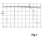
- the capacitance C is a function of the number of cycles n two cells produced according to the example are shown.
- the two cells 1.15 or 1.4 C constant current (corresponding to 600 mAh for curve 1 and 750 mAh for curve 2) are charged to 4.2 volts The voltage was then held for 3 hours and then constant at 1.15 or 1.4 C.
- Current 600 mAh for curve 1 and 750 mAh for curve 2 to 3.0 volts discharged. From the slight drop in the curves thus obtained, it can be seen that the cells produced in this way are highly reliable.
Abstract
Description
Gegenstand der Erfindung ist ein Verfahren zur Herstellung eines Elektroden-/Separatorverbunds für galvanische Elemente, die mindestens eine Lithium interkalierende Elektrode enthalten, in deren Polymermatrix im Polymer unlösliche elektrochemisch aktive Materialien fein dispergiert sind. Weiterhin ist Gegenstand der Erfindung ein galvanisches Element mit nach dem Verfahren hergestellten Separator-/Elektrodenverbund.The invention relates to a method for producing an electrode / separator assembly for galvanic elements that at least contain a lithium intercalating electrode in its polymer matrix finely dispersed electrochemically active materials insoluble in the polymer are. The invention further relates to a galvanic element with separator / electrode assembly produced by the process.
Zur Herstellung von galvanischen Elementen mit folienförmigen Elektroden, die als aktive Massen Lithium interkalierende Materialien besitzen, sind die verschiedensten Verfahren bekannt:For the production of galvanic elements with foil-shaped electrodes, which have lithium intercalating materials as active materials, A wide variety of processes are known:
Dem Dokument EP 954 042 A1 ist ein Lithium-lonen-Akkumulator zu entnehmen, bei dem die positiven und negativen Folienelektroden mit einem Separator durch eine haftvermittelnde Harzschicht verbunden sind. Die Haftung vermittelnden Schichten können insbesondere einen unerwünschten Isolationseffekt zwischen Elektrode und Separator, nämlich die Hemmung der Elektrolytdiffusion und damit einen erhöhten Innenwiderstand mit sich bringen. Darüber hinaus können durch solche Schichten unerwünschte Stoffe in die Zelle gelangen.Document EP 954 042 A1 includes a lithium-ion battery remove, in which the positive and negative foil electrodes with connected to a separator by an adhesion-promoting resin layer are. The layers which impart adhesion can in particular have one undesirable insulation effect between electrode and separator, namely the inhibition of electrolyte diffusion and thus an increased internal resistance entail. In addition, through such Layers of unwanted substances get into the cell.
Dem Dokument EP 1 056 142 A1 ist eine Lithium-lonen-Zelle zu entnehmen,
bei der zwischen positiven und negativen Elektrodenfolien ein
Gelelektrolyt angeordnet ist. Das Gel besteht insbesondere aus Polyvinylidenfluorid
oder Copolymeren von Polyvinylidenfluorid wie beispielsweise
Hexafluorpropylen. Die Herstellung solcher Zellen ist aufwendig,
da eine Verarbeitung der Elektroden und des Gelelektrolyten im Trockenraum
notwendig ist. Darüber hinaus wird durch solche Elektrolyte
oft keine ausreichende Leitfähigkeit erzielt.A lithium-ion cell can be found in
Aus dem Dokument DE 19 916 041 A1 ist ein Verfahren bekannt, bei dem auf eine mechanisch stabile Trägerfolie beispielsweise eine Kupferfolie, ein graphithaltige Pastenmischung und anschließend ein Separatorband, bestehend aus einer Polymermischung und SiO2 in Pastenform aufgebracht wird und zu einer Folie verarbeitet wird. Um Durchkontaktierungen der aktiven Masse durch das gelartige Separatorband zu vermeiden, sind bei derartigen Verfahren verhältnismäßig dicke Separatorschichten notwendig, die den Innenwiderstand der Zelle erhöhen und die Energiedichte herabsetzen.From document DE 19 916 041 A1 a method is known in which, for example, a copper foil, a graphite-containing paste mixture and then a separator tape, consisting of a polymer mixture and SiO 2 in paste form, is applied to a mechanically stable carrier film and processed into a film. In order to avoid plated-through holes in the active mass through the gel-like separator tape, relatively thick separator layers are necessary in such methods, which increase the internal resistance of the cell and reduce the energy density.
Üblicherweise liegt einer Elektrode, die in solchen galvanischen Elementen verwendet wird, eine nasschemische hergestellte Folie zugrunde, bei der eine erhebliche Menge, in der Regel mehr als 70 Gewichtsprozent aktives Material, in einem gelösten Binderpolymer suspendiert und zu einer Folie mittels Rakeln ausgezogen wird. Die Suspension enthält gegebenenfalls noch Weichmacher und Leitfähigkeitsverbesserer. Der Zellverbund wird hergestellt durch Lamination der Elektrodenfolien auf folienartige Ableiterelektroden, und der so erhaltene Verbund wird mit dem Separator in einem weiteren Laminationsschritt verbunden. Die Laminierungstemperatur liegt üblicherweise bei 110°C bis 140°C und erfolgt bei einem definierten Druck in einem Bandlaminator.Usually an electrode lies in such galvanic elements is used, based on a wet-chemical manufactured film, with a significant amount, usually more than 70 percent by weight active material suspended in a dissolved binder polymer and is drawn out to a film by means of doctor blades. The suspension contains optionally plasticizers and conductivity improvers. The Cell composite is produced by lamination of the electrode foils foil-like arrester electrodes, and the composite thus obtained is with connected to the separator in a further lamination step. The The lamination temperature is usually 110 ° C to 140 ° C and takes place at a defined pressure in a tape laminator.
Das US-Patent 5 460 904 beschreibt beispielsweise eine solche Vorgehensweise. Dieser Druckschrift sind Lithium interkalierende Elektroden zu entnehmen, bei denen die aktive Masse in einer Matrix aus Polyvinylidendifluorid-Hexafluorpropylen-Copolymer verteilt ist. Zwischen diesen Elektroden ist ein aus den gleichen Materialien hergestellter Gel-Separator mit SiO2 als Füllstoff angeordnet. Die Elektroden und der Separator werden anschließend zu einem Zellverbund laminiert.For example, U.S. Patent 5,460,904 describes such an approach. This publication shows lithium intercalating electrodes in which the active composition is distributed in a matrix made of polyvinylidene difluoride-hexafluoropropylene copolymer. A gel separator made of the same materials with SiO 2 as filler is arranged between these electrodes. The electrodes and the separator are then laminated into a cell assembly.
Füllstoffseparatoren mit einem Polymer als Binder und einer binären
Sauerstoffverbindung wie Al2O3 oder insbesondere abgerauchtem SiO2
als Füllstoff mit sehr großer effektiver Oberfläche bringen hierbei mehrere
inhärente Probleme mit sich. Da in 4 Volt-Systemen aus Stabilitätsgründen
nur fluorhaltige Leitsalze wie LiPF6, LiBF4, etc. eingesetzt werden
können, diese aber gleichzeitig sehr hydrolyseempfindlich sind, und
großtechnisch aufwandsbedingt immer ein Restwassergehalt im Bereich
von einigen Zehn bis einigen Hundert ppm in Kauf genommen werden
muss, können sauerstoffhaltige Füllstoffe einen wie folgt beschriebenen
Zyklus initiieren. Das Leitsalz zerfällt dabei zunächst gemäß
Dieser Zerfall tritt in sehr geringem Maße mit der Zeit ein und wird durch
Einflüsse wie Licht oder erhöhte Temperatur beschleunigt. PF5 ist das
hydrolyseempfindliche Erstzersetzungsprodukt, es reagiert mit Spuren
von Wasser unter Freisetzung von HF
HF reagiert in der Regel mit sauerstoffhaltigen Verbindungen unter Freisetzung
von Wasser. Als Beispiel sei die Reaktion mit SiO2 ausgeführt.
Die Reaktion läuft bei Raumtemperatur zwar nur in sehr geringem Maße ab, wird aber über die Nachlieferung von H2O immer aufrecht erhalten.The reaction takes place only to a very small extent at room temperature, but is always maintained by the subsequent delivery of H 2 O.
Ein zu hoher HF-Gehalt wirkt mit der Zeit zwangsläufig negativ durch Korrosion bzw. Passivierung der Ableitelektroden wie auch Zerstörung und Auflösung der sogenannten SEIs ("Solid Electrolyte Interfaces"), ionenleitender Festelektrolytschichten, die ein zumindest kinetisch stabiles Reaktionsprodukt der Erstzersetzung des flüssigen organischen Elektrolyten beim Laden der Zelle bilden und damit eine weitere Zersetzung des flüssigen organischen Lithiumelektrolyten unterbinden. Dieser Auflösungsprozess kann insbesondere bei erhöhter Temperatur (60°C - 80° C) stark beschleunigt sein und zur Gasung der Zelle führen. Ein langsames Anwachsen der SEIs bei Raumtemperatur durch Lösen und Neuaufbau erhöht den Zellwiderstand, dies macht sich bei gleicher Entladestromstärke durch Abnahme der Kapazität über die Zyklenzahl bemerkbar.A too high HF content inevitably has a negative effect over time Corrosion or passivation of the lead electrodes as well as destruction and dissolution of the so-called SEIs ("Solid Electrolyte Interfaces"), ion-conducting solid electrolyte layers that are at least kinetically stable Reaction product of the first decomposition of the liquid organic electrolyte form when loading the cell and thus further decomposition prevent the liquid organic lithium electrolyte. This The dissolution process can take place especially at elevated temperatures (60 ° C - 80 ° C) must be strongly accelerated and lead to gassing of the cell. On slow growth of the SEIs at room temperature by dissolving and Reconstruction increases the cell resistance, this is done with the same discharge current noticeable by a decrease in capacity over the number of cycles.
Ein zweiter großer Schwachpunkt dieser Füllstoffseparatoren besteht in ihrer mechanischen Konsistenz. Damit werden diese Separateren, insbesondere wenn noch erhebliche Mengen von Weichmachern eingearbeitet werden müssen, sehr laminationsempfindlich, und man muss die Gefahr von Kurzschlüssen durch Dicke kompensieren. Dies wiederum erhöht den Widerstand, reduziert damit die Energiedichte und bringt mehr Füllstoffmaterial ein, das nach den oben beschriebenen Reaktionswegen wechselseitig und aufschaukelnd Wasser und Flusssäure generiert. Zudem muss gegebenenfalls noch der Weichmacher wieder aufwendig extrahiert werden, da dieser in der Regel elektrochemisch inkompatibel ist.A second major weakness of these filler separators is in their mechanical consistency. This makes these more separate, in particular if significant amounts of plasticizers are still incorporated have to be very sensitive to lamination, and you have to Compensate for the risk of short circuits due to the thickness. this in turn increases resistance, reduces energy density and brings more filler material according to the reaction pathways described above reciprocally and rocking water and hydrofluoric acid generated. In addition, the plasticizer may have to be used again can be extracted in a complex manner, since this is usually electrochemical is incompatible.
Aus diesen Gründen sind chemisch inerte, dabei sehr dünne aber dennoch stabile und großtechnisch verarbeitbare Separatormaterialien von großem Interesse. Polyolefine wie Polypropylen (PP), Polyethylen (PE) oder Sequenzen (z.B. PE/PP/PE) dieser Materialien erfüllen in hohem Maße diese Anforderungen und kommen daher in gewickelten Lithiumzellen schon seit langer Zeit zum Einsatz. Überdies besitzen die Polyolefinseparatoren einen inhärenten Sicherheitsmechanismus, den sogenannten "Shut down": In einer kritischen Zellsituation wie Kurzschluss oder äußerer mechanischer Penetration verbunden mit raschem Anstieg der Temperatur dichten sich die mit flüssigem Elektrolyten gefüllten Poren durch das Zusammenschmelzen des Separators selbst, der innere, ionische Stromfluss der Zelle wird unterbrochen, der Zellwiderstand steigt rapide an und die Zelle kann sich nicht mehr weiter erhitzen. Zudem sind Polyolefinseparatoren kostengünstiger und umweltfreundlicher. Dabei sind die zuvor beschriebenen Systeme jedoch immer auf einen externen Druck angewiesen, den man entweder aufwendig über Federn, besondere eigenverspannende Wickeltechnologien der trockenen Zelle, spezielle Gehäuseformen mit Vorspannungen und vergleichbare Vorrichtungen aufbringen muss. Wünschenswert wäre jedoch eine Zelle, die bereits ohne Gehäuse einen mechanischen Zusammenhalt besitzt. Dies eröffnet neue, extrem dünne oder flächige Bauformen und ist ganz allgemein für einen verbesserten Elektroden-/Separator-Kontakt von Vorteil.For these reasons, they are chemically inert, yet very thin stable and industrially processable separator materials from great interest. Polyolefins such as polypropylene (PP), polyethylene (PE) or sequences (e.g. PE / PP / PE) of these materials meet in high Measure these requirements and therefore come in wound lithium cells used for a long time. In addition, the polyolefin separators have an inherent security mechanism, the so-called "Shut down": In a critical cell situation such as a short circuit or external mechanical penetration associated with rapid increase The pores filled with liquid electrolyte are sealed against the temperature by melting the separator itself, the inner, Ionic current flow of the cell is interrupted, the cell resistance rises rapidly and the cell can no longer heat up. moreover are polyolefin separators cheaper and more environmentally friendly. However, the systems described above are always on an external pressure instructed, which is either expensive Springs, special self-tensioning winding technologies of dry Cell, special housing shapes with preloads and comparable Devices must apply. However, one would be desirable Cell that already has a mechanical cohesion without housing has. This opens up new, extremely thin or flat designs and is generally for improved electrode / separator contact advantageous.
Es ist auch bekannt, beschichtete PP, PE Separatoren oder Sequenzen aus diesen, die mit dem Elektrodenbinder beschichtet sind, zu verwenden. Aus dem Dokument WO/0069010 ist beispielsweise eine Lithium-lonen-Zelle entnehmbar, bei der als Separator zwischen positiven und negativen Elektroden ein Polyolefinseparator verwendet wird, welcher mit dem gleichen Binderpolymer beschichtet ist, welches in den Elektroden zum Einsatz kommt. Diese Verfahrensweise ist jedoch aufwendig, da der Separator zuerst nasschemisch beschichtet und anschließend noch laminiert werden muss und schränkt die Herstellungsparameter für den Zellverbund stark ein.It is also known to use coated PP, PE separators or sequences out of these, which are coated with the electrode binder. For example, a lithium-ion cell is known from document WO / 0069010 removable, as a separator between positive and negative electrodes a polyolefin separator is used, which is coated with the same binder polymer that is in the electrodes is used. However, this procedure is complex, because the separator is first coated with a wet chemical and then still has to be laminated and limits the manufacturing parameters for the cell network strongly.
Der Erfindung liegt die Aufgabe zugrunde, ein Verfahren zur Herstellung eines Elektroden-/Separatorverbunds der eingangs genannten Art anzugeben, welches einfach durchführbar ist, bei dem insbesondere die Verarbeitung unter beliebiger Atmosphäre und mit einer weiten Auswahl Polyolefin-basierter Separatoren und Elektrodenmaterial durchgeführt werden kann.The invention has for its object a method for manufacturing specify an electrode / separator assembly of the type mentioned at the outset, which is easy to carry out, in which in particular the Processing in any atmosphere and with a wide selection Polyolefin-based separators and electrode material performed can be.
Diese Aufgabe wird erfindungsgemäß bei einem Verfahren der eingangs
genannten Art durch die Merkmale des Anspruchs 1 gelöst. In den weiteren
Ansprüchen sind vorteilhafte Ausgestaltungen des Verfahrens und
galvanische Elemente mit nach dem Verfahren hergestellten Elektroden/Separatorverbunden
angegeben. Der Wortlaut der Ansprüche wird
durch ausdrückliche Bezugnahme zum Inhalt der Beschreibung gemacht.This object is achieved according to the invention in a method of the beginning
mentioned type solved by the features of
Durch Anwendung des erfindungsgemäßen Verfahrens kann das Problem, einen unbeschichteten Separator zu verwenden, auf folgende Weisen gelöst werden: Man verwendet eine Temperatur nahe beim Schmelz-/ bzw. Erweichungspunkt des Polymermaterials der Elektrode als Laminationstemperatur und einen Separator, dessen Schmelztemperatur höher liegt, um ein Durchkontaktieren zu verhindern. Ein Beispiel für eine derartige Ausgestaltung ist als Elektrodenpolymer PVDF-HFP (Polyvinylidenfluorid-Hexafluorpropylen) mit einem so abgestimmten PVDF/HFP-Verhältnis, dass der Schmelz- bzw. Erweichungspunkt im Bereich von 140°C - 150° C liegt (z. B. Powerflex von Elf Atofina). Der Separator ist ein einlagiger PP-Separator, dessen Schmelzpunkt bei ca. 160° C liegt. Der Elektrodenbinder PVDF-HFP dringt bei seiner Erweichung etwas in die Poren des PP-Separators ein, und dadurch wird eine Verankerung zwischen Elektrode und Separator erreicht.By using the method according to the invention, the problem of To use an uncoated separator in the following ways be solved: a temperature close to the Melting point or softening point of the polymer material of the electrode as a lamination temperature and a separator, its melting temperature is higher to prevent through-plating. An example PVDF-HFP is the electrode polymer for such a configuration (Polyvinylidene fluoride-hexafluoropropylene) with a so tuned PVDF / HFP ratio that the melting or softening point in the Range of 140 ° C - 150 ° C (e.g. Powerflex from Elf Atofina). The Separator is a single-layer PP separator whose melting point is approx. 160 ° C. The electrode binder PVDF-HFP penetrates when it softens something in the pores of the PP separator, and this creates a Anchoring between electrode and separator reached.
Beim Einsatz der Heißlamination, insbesondere der Bandlamination, hat sich überraschenderweise herausgestellt, dass Zellen mit einem PP/PE/PP basierten Separator bei Laminationstemperaturen im Bereich des Schmelz- bzw. Erweichungspunktes hergestellt werden können, obwohl die Shut-down Temperatur von PE bei 120° C liegt. Die kurze Verweilzeit im Laminator bei gegebenem Druck führt offenbar trotz der hohen Temperatur statt eines Porenschlusses zu einer Wieder-Verporung des Separators oder wenigstens zu einer Offenhaltung der bestehenden Poren.When using hot lamination, especially band lamination, has surprisingly it turned out that cells with a PP / PE / PP based separator at lamination temperatures in the range the melting or softening point can be produced, although the shutdown temperature of PE is 120 ° C. The short Residence time in the laminator at a given pressure apparently leads despite the high temperature instead of a pore closure for re-porosity of the separator or at least to keep the existing pores.
Will man zusätzlich oder ausschließlich den Schmelz- bzw. Erweichungspunkt des Separators zur Schaffung des Elektroden-/Separatorverbundes nutzen, bleibt immer die latente Gefahr einer Durchkontaktierung des Separators. Daher bietet sich eine Sequenz der Art PE/PP/PE an. PP mit höherem Schmelzpunkt von ca. 160 ° C bleibt als Kernfolie und verhindert das Durchkontaktieren, PE könnte damit bei ca. 120°C - 130°C sogar derart thermoplastisch verformt werden, ohne dass es dabei zu einem nachteiligen Porenschluss kommt. Eine besondere Ausgestaltung besteht darin, die Porosität der außen liegenden PE-Lagen zusätzlich noch relativ grob zu wählen, um eine optimierte Elektrolytpenetration zu gewährleisten.If you want the melting or softening point additionally or exclusively of the separator to create the electrode / separator assembly use, there is always the latent risk of through-plating of the separator. Therefore a sequence of the type PE / PP / PE is available on. PP with a higher melting point of approx. 160 ° C remains as the core film and prevents through-plating, PE could thus at approx. 120 ° C - 130 ° C can even be thermoplastic deformed without it there is an adverse pore closure. A special design consists of the porosity of the outer PE layers in addition to choose relatively rough to optimize electrolyte penetration to ensure.
In einer weiteren Ausgestaltung des erfindungsgemäßen Verfahrens kann auch ein teil- bzw. punktbeschichteter Separator verwendet werden, die Punktbeschichtung mit einem die Haftung erhöhenden Material übernimmt hierbei die Aufgabe eines thermoplastisch wirkenden Klebers. Die Fläche der Punktbeschichtung, typischerweise 5 %, ist dabei so gering gewählt, dass eine fehlende oder ungenügende Elektrolytpenetration in diesen Bereichen sowie elektrochemische Seitenreaktionen an der Phasengrenze Separator/negative Elektrode, immer dort wo die Beschichtung lokalisiert ist, billigend in Kauf genommen werden können.In a further embodiment of the method according to the invention a partially or point-coated separator can also be used, the spot coating with a material that increases the adhesion takes on the task of a thermoplastic adhesive. The area of the dot coating, typically 5%, is included chosen so low that a missing or insufficient electrolyte penetration in these areas as well as electrochemical side reactions at the phase boundary separator / negative electrode, wherever the Coating is localized, can be accepted with approval.
Die zusätzliche Beschichtung kann 1% - 60% der Separatorfläche, vorzugsweise 5% - 10% der Separatoroberfläche, bedecken und kann insbesondere aus Polyvinylidenfluorid oder Polyvinylidenfluorid und Hexafluorpropylen bestehen.The additional coating can be 1% - 60% of the separator area, preferably 5% - 10% of the separator surface, cover and can in particular made of polyvinylidene fluoride or polyvinylidene fluoride and hexafluoropropylene consist.
Durch die zusätzlich Teilbeschichtung, die eine Haftung zwischen Elektrode und Separator vermittelt, wird gewährleistet, dass diese Bauteile im Fertigungsprozess auch vor der Heißlamination einen ausreichenden Zusammenhalt besitzen.Due to the additional partial coating, the adhesion between the electrode and separator, it is ensured that these components in the A sufficient manufacturing process even before hot lamination Have cohesion.
Weiterhin ist es erfindungsgemäß vorteilhaft, eine Coronabehandlung der Separatoroberfläche vorzunehmen. Durch einen Elektronenstrahl wird diese gereinigt, modifiziert und aktiviert, was zu erheblich verbesserten Haftungseigenschaften führt.It is also advantageous according to the invention to have a corona treatment the separator surface. Through an electron beam it is cleaned, modified and activated, which leads to significantly improved Adhesion properties leads.
Eine geringere bzw. lokal sogar fehlende Haftung des Separators kann bei der Aktivierung der Zelle, also der Tränkung mit flüssigem organischem Lithiumelektrolyten, für dessen gleichmäßige und schnelle Penetration von Vorteil sein. Auch sicherheitstechnisch ist das vorteilhaft, denn bei einer ungewollten Überladung der Zelle führt die Gasentwicklung als Folge der Zersetzung des flüssigen Elektrolyten zu einer leichteren Dekontaktierung und damit zu der Unterbindung weiteren Stromflusses.A lower or locally even missing adhesion of the separator can upon activation of the cell, i.e. the impregnation with liquid organic Lithium electrolyte, for its uniform and quick penetration be an advantage. This is also advantageous in terms of safety because in the event of an undesired overloading of the cell, gas development leads as a result of the decomposition of the liquid electrolyte to a lighter one Decontacting and thus preventing further current flow.
Als für einen erfindungsgemäßen Elektroden-/Separatorverbund geeignete Polymere werden Polyvinylidenfluorid und Hexafluorpropylen oder auch wasserlösliche Binder verwendet. Als Lösungsmittel können dann beispielsweise N-Methylpyrolidin-2-on, Aceton oder Wasser Verwendung finden. Das poröse Separatormaterial besteht aus Polyolefinen, aus Polypropylen, Polyethylen oder kann mehrlagig aus verschiedenen dieser Materialien hergestellt sein, deren Porosität variieren kann. Die Elektroden und/oder die Separatorbeschichtung können einen Plastifizierer enthalten.As suitable for an electrode / separator assembly according to the invention Polymers become polyvinylidene fluoride and hexafluoropropylene or also used water-soluble binders. Then as a solvent for example, N-methylpyrolidin-2-one, acetone or water Find. The porous separator material consists of polyolefins, Made of polypropylene, polyethylene or can be multi-layered from different of these materials, the porosity of which may vary. The Electrodes and / or the separator coating can be a plasticizer contain.
Als Material der negativen Elektrode kommen metallisches Lithium, Lithium-legierbare Metalle oder graphitisierter Kohlenstoff mit Modifikationen in Betracht sowie Interkalationsverbindungen aus Mischoxiden mit geeigneter Spannungslage wie Li4/3[Ti5/3]O4, während die positive Elektrode als Lithium interkalierendes Material eine Lithiumkobalt-, -nickeloder -mangan-sauerstoffverbindung enthält, die gegebenenfalls mit Lithium, Magnesium, Aluminium oder Fluor zusätzlich stabilisiert sein kann.Metallic lithium, lithium-alloyable metals or graphitized carbon with modifications come into consideration as the material of the negative electrode, and intercalation compounds of mixed oxides with a suitable voltage level, such as Li 4/3 [Ti 5/3 ] O 4 , while the positive electrode as lithium intercalating material Contains lithium cobalt, nickel or manganese oxygen compound, which can optionally be additionally stabilized with lithium, magnesium, aluminum or fluorine.
Die Pastenmischungen für negative Elektrodenfolien enthalten zwischen
55 und 95 Gewichtsprozent, vorzugsweise 65 bis 85 Gewichtsprozent
der genannten Materialklassen. Die Pastenmischung für positive Elektroden
enthält 65 bis 98 Gewichtsprozent, vorzugsweise 65 bis 95 Gewichtsprozent
des positiven Elektrodenmaterials, jeweils bezogen auf
die Trockenmasse. Erfindungsgemäße Nasspastenmischungen enthalten
25 bis 50 Gewichtsprozent, vorzugsweise 35 bis 45 Gewichtsprozent,
Trockenmasse. Der Rest ist Lösemittel, dass dann an 100% bezogen
auf die Gesamtnassmasse aufgefüllt wird. Das PVDF/HFP-Verhältnis
liegt bei positiven Elektrodenfolien zwischen maximal 99,5 und minimal
0,5, vorzugsweise zwischen maximal 80 und minimal 20. Das Verhältnis
der Molekulargewichte zwischen PVDF/HFP liegt zwischen 3,2
und 2,8, vorzugsweise zwischen 2,3 und 2,5. The paste mixtures for negative electrode foils contain between
55 and 95 percent by weight, preferably 65 to 85 percent by weight
of the material classes mentioned. The paste mix for positive electrodes
contains 65 to 98 percent by weight, preferably 65 to 95 percent by weight
of the positive electrode material, each based on
the dry matter. Contain wet paste mixtures according to the
Bei negativen Elektrodenfolien liegt das PVDF/HFP-Verhältnis zwischen 99,5 und 0,5, vorzugsweise zwischen 85 und 15. Das Verhältnis der Molekulargewichte liegt zwischen 3,2 und 2,8, vorzugsweise zwischen 2,3 und 2,5.In the case of negative electrode foils, the PVDF / HFP ratio is between 99.5 and 0.5, preferably between 85 and 15. The ratio of the molecular weights is between 3.2 and 2.8, preferably between 2.3 and 2.5.
Die Masse wird so hergestellt, dass die Viskosität der Ausgangspaste auf 1 bis 10 Pascal, vorzugsweise 3 bis 6 Pascal, eingestellt ist.The mass is made so that the viscosity of the starting paste is set to 1 to 10 Pascals, preferably 3 to 6 Pascals.
Zur Herstellung von galvanischen Elementen werden die Elektroden zunächst entweder direkt auf die Ableiter aufgerakelt oder über den Zwischenschritt des Aufrakelns auf eine Trägerfolie und folgende Heißlamination hergestellt. Der Zellaufbau erfolgt durch Heißlamination der Elektroden und des Separators, vorzugsweise in einem symmetrischen Aufbau der Art Elektrode B / Separator / Elektrode A / Separator / Elektrode B, um ein Biegen der Zelle aufgrund eines asymmetrischen Aufbaus zu unterbinden.The electrodes are first used to manufacture galvanic elements either doctored directly onto the arrester or via the intermediate step of knife coating onto a carrier film and subsequent hot lamination manufactured. The cells are built up by hot lamination of the electrodes and the separator, preferably in a symmetrical structure of the type electrode B / separator / electrode A / separator / electrode B to bend the cell due to an asymmetrical structure prevention.
Eine pastöse Masse für die negative Elektrode wird hergestellt, indem 4812 g Kugelgraphit (MCMB 25-28, Osaka Gas) mit 138 g Leitruß (Super P, Erachem/Sedema) und 619 g Powerflex in 5 I Aceton innig vermischt und dann direkt auf eine Kupferfolie doppelseitig ausgerakelt werden. Der Kupferfolie wurde zuvor eine Oberflächenrauhigkeit durch die elektrochemische Abscheidung von Kupferkristalliten aufgeprägt, zum Korrosionsschutz bis zur abschließenden Verarbeitung wurde die so erhaltene Folie chromatisiert. Eine pastöse Masse für die positive Elektrode wird hergestellt, indem 2973 g LiCoO2, 206 g Leitruß (Super P, Erachem/Sedema) und 310 g Powerflex in 5 I Aceton innig vermischt und dann direkt auf ein unbehandeltes Aluminiumstreckmetall (2 Al 6-077 F, Delker) beidseitig ausgerakelt werden Die negative Elektrode wird in 6 x 3 cm Stücke mit Ableitfähnchen ausgestanzt, darauf wird bei 130° C und 10 kg Anpressdruck ein einlagiger PP-Separator (Celgard 2500) auflaminiert. Geeignet ausgestanzte Kathodenstücke mit Ableitfähnchen werden bei 140° C und einem Druck von 10 kg beidseitig auf den so erhaltenen Verbund auflaminiert. Acht solcher Bizellen werden an den Ableitfähnchen mit einem massiven Ni-Ableiter (70 pm) auf der negativen und einem Al-Ableiter (70 pm) auf der positiven Seite ultraschallverschweißt, der so erhaltene Stapel in beidseitig beschichtete tiefgezogene Aluminimumfolie verpackt und mit 1 M LiPF6 in 7:3 Gewichtsprozent Diethylcarbonat: Ethlyencarbonat aktiviert.A pasty mass for the negative electrode is produced by intimately mixing 4812 g spherical graphite (MCMB 25-28, Osaka Gas) with 138 g conductive carbon black (Super P, Erachem / Sedema) and 619 g Powerflex in 5 l acetone and then directly on a Copper foil can be scraped out on both sides. A surface roughness was previously impressed on the copper foil by the electrochemical deposition of copper crystallites, and the foil thus obtained was chromated to prevent corrosion until the final processing. A pasty mass for the positive electrode is produced by intimately mixing 2973 g LiCoO 2 , 206 g conductive carbon black (Super P, Erachem / Sedema) and 310 g Powerflex in 5 l acetone and then directly on an untreated expanded aluminum (2 Al 6-077 F, Delker) are scraped out on both sides. The negative electrode is punched into 6 x 3 cm pieces with lead flags, a single-layer PP separator (Celgard 2500) is laminated onto it at 130 ° C and 10 kg pressure. Appropriately punched cathode pieces with lead flags are laminated on both sides at 140 ° C. and a pressure of 10 kg onto the composite thus obtained. Eight of these bicells are ultrasonically welded to the lead tags with a solid Ni conductor (70 pm) on the negative side and an Al conductor (70 pm) on the positive side, the stack thus obtained is packed in deep-drawn aluminum foil coated on both sides and with 1 M LiPF 6 in 7: 3 weight percent diethyl carbonate: ethylene carbonate activated.
In Figur 1 ist die Kapazität C in Abhängigkeit von der Zyklenzahl n für
zwei gemäß dem Beispiel hergestellte Zellen dargestellt. Die zwei Zellen
werden mit ca. 1,15 bzw. 1,4 C konstantem Strom (entsprechend 600
mAh bei Kurve 1 und 750 mAh bei Kurve 2) auf 4,2 Volt geladen, die
Spannung dann für 3h gehalten und dann mit 1,15 bzw. 1,4 C konstantem
Strom (600 mAh bei Kurve 1 und 750 mAh bei Kurve 2) auf 3,0 Volt
entladen. Aus dem geringen Abfall der so erhaltenen Kurven ist ersichtlich,
dass die so hergestellten Zellen eine hohe Zuverlässigkeit besitzen.In Figure 1, the capacitance C is a function of the number of cycles n
two cells produced according to the example are shown. The two cells
1.15 or 1.4 C constant current (corresponding to 600
mAh for
Claims (10)
Applications Claiming Priority (2)
| Application Number | Priority Date | Filing Date | Title |
|---|---|---|---|
| DE10150227A DE10150227A1 (en) | 2001-10-11 | 2001-10-11 | Process for producing an electrode / separator assembly for galvanic elements |
| DE10150227 | 2001-10-11 |
Publications (2)
| Publication Number | Publication Date |
|---|---|
| EP1302993A2 true EP1302993A2 (en) | 2003-04-16 |
| EP1302993A3 EP1302993A3 (en) | 2005-03-02 |
Family
ID=7702197
Family Applications (1)
| Application Number | Title | Priority Date | Filing Date |
|---|---|---|---|
| EP02021947A Withdrawn EP1302993A3 (en) | 2001-10-11 | 2002-09-28 | Method of manufacturing an electrode-separator unit for galvanic elements |
Country Status (6)
| Country | Link |
|---|---|
| US (1) | US20030072999A1 (en) |
| EP (1) | EP1302993A3 (en) |
| JP (1) | JP2003163033A (en) |
| KR (1) | KR20030030960A (en) |
| CN (1) | CN1417873A (en) |
| DE (1) | DE10150227A1 (en) |
Families Citing this family (14)
| Publication number | Priority date | Publication date | Assignee | Title |
|---|---|---|---|---|
| JP2005158816A (en) * | 2003-11-20 | 2005-06-16 | Tdk Corp | Electrochemical device and manufacturing method thereof |
| US8784595B2 (en) * | 2004-07-26 | 2014-07-22 | Bathium Canana Inc. | Process for laminating components of an electrochemical cell |
| JP4581547B2 (en) * | 2004-08-05 | 2010-11-17 | パナソニック株式会社 | Non-aqueous electrolyte secondary battery |
| JP4984448B2 (en) * | 2005-07-12 | 2012-07-25 | 日産自動車株式会社 | Manufacturing method of secondary battery |
| CN102144058B (en) | 2008-09-04 | 2012-07-11 | 大和纺控股株式会社 | Fibrous mass, composite of conductive substrate with fibrous mass, and processes for producing same |
| JP5381078B2 (en) * | 2008-12-19 | 2014-01-08 | 日産自動車株式会社 | Electrode and manufacturing method thereof |
| US9276246B2 (en) * | 2009-05-20 | 2016-03-01 | Samsung Electronics Co., Ltd. | Treatment and adhesive for microporous membranes |
| KR101254693B1 (en) * | 2011-02-15 | 2013-04-15 | 주식회사 엘지화학 | A separator, the manufacturing method thereof, and electrochemical device containing the same |
| US10522809B2 (en) | 2012-07-18 | 2019-12-31 | Sumitomo Chemical Company, Limited | Adhesive layer, layer, and composition |
| KR102086416B1 (en) * | 2012-07-30 | 2020-03-09 | 데이진 가부시키가이샤 | Separator for non-aqueous electrolyte battery, and non-aqueous electrolyte battery |
| EP2988356A1 (en) * | 2014-08-18 | 2016-02-24 | Manz AG | Method and device for the production of a galvanic element and galvanic element |
| JP6570926B2 (en) * | 2015-09-03 | 2019-09-04 | 株式会社エンビジョンAescジャパン | Method for producing lithium ion secondary battery |
| CN110622339B (en) * | 2017-05-17 | 2022-12-23 | 帝人株式会社 | Separator for nonaqueous secondary battery, and method for producing nonaqueous secondary battery |
| KR102293887B1 (en) * | 2017-07-25 | 2021-08-25 | 주식회사 엘지에너지솔루션 | Battery Separator Having Material for Reducing Hydrofluoric Acid |
Citations (3)
| Publication number | Priority date | Publication date | Assignee | Title |
|---|---|---|---|---|
| US5778515A (en) * | 1997-04-11 | 1998-07-14 | Valence Technology, Inc. | Methods of fabricating electrochemical cells |
| WO1999019917A2 (en) * | 1997-10-09 | 1999-04-22 | Basf Aktiengesellschaft | Composite suitable for use in electrochemical cells |
| WO2001073871A2 (en) * | 2000-03-29 | 2001-10-04 | Valence Technology (Nevada), Inc. | Method of making bonded-electrode rechargeable electrochemical cells |
Family Cites Families (3)
| Publication number | Priority date | Publication date | Assignee | Title |
|---|---|---|---|---|
| JP3397351B2 (en) * | 1992-12-18 | 2003-04-14 | キヤノン株式会社 | Prismatic or sheet type battery and manufacturing method thereof |
| US5460904A (en) * | 1993-08-23 | 1995-10-24 | Bell Communications Research, Inc. | Electrolyte activatable lithium-ion rechargeable battery cell |
| US5720780A (en) * | 1996-11-04 | 1998-02-24 | Valence Technology, Inc. | Film forming method for lithium ion rechargeable batteries |
-
2001
- 2001-10-11 DE DE10150227A patent/DE10150227A1/en not_active Withdrawn
-
2002
- 2002-09-28 EP EP02021947A patent/EP1302993A3/en not_active Withdrawn
- 2002-10-08 JP JP2002294982A patent/JP2003163033A/en active Pending
- 2002-10-10 US US10/268,454 patent/US20030072999A1/en not_active Abandoned
- 2002-10-11 CN CN02151410A patent/CN1417873A/en active Pending
- 2002-10-11 KR KR1020020061959A patent/KR20030030960A/en not_active Application Discontinuation
Patent Citations (3)
| Publication number | Priority date | Publication date | Assignee | Title |
|---|---|---|---|---|
| US5778515A (en) * | 1997-04-11 | 1998-07-14 | Valence Technology, Inc. | Methods of fabricating electrochemical cells |
| WO1999019917A2 (en) * | 1997-10-09 | 1999-04-22 | Basf Aktiengesellschaft | Composite suitable for use in electrochemical cells |
| WO2001073871A2 (en) * | 2000-03-29 | 2001-10-04 | Valence Technology (Nevada), Inc. | Method of making bonded-electrode rechargeable electrochemical cells |
Also Published As
| Publication number | Publication date |
|---|---|
| CN1417873A (en) | 2003-05-14 |
| EP1302993A3 (en) | 2005-03-02 |
| DE10150227A1 (en) | 2003-04-17 |
| JP2003163033A (en) | 2003-06-06 |
| KR20030030960A (en) | 2003-04-18 |
| US20030072999A1 (en) | 2003-04-17 |
Similar Documents
| Publication | Publication Date | Title |
|---|---|---|
| DE60103407T2 (en) | ELECTRODE OF PARTICLES AND ELECTROLYTIC FOR A RECHARGEABLE LITHIUM-ION BATTERY | |
| DE102015101450B4 (en) | Sulfur-based positive electrode active material | |
| DE69720386T2 (en) | Secondary lithium-ion batteries and manufacturing process | |
| DE102015112182B4 (en) | Solid lithium secondary battery and manufacturing method therefor | |
| EP3208869B1 (en) | Rechargeable electrochemical cell | |
| DE69637084T2 (en) | LITHIUM CELL AND METHOD FOR THE PRODUCTION THEREOF | |
| EP1359637B1 (en) | Method for manufacturing of a galvanic element | |
| DE112014003358T5 (en) | Lithium-based battery electrodes | |
| DE69631751T2 (en) | ELECTROLYTIC CELL AND ELECTROLYTIC METHOD | |
| EP1302993A2 (en) | Method of manufacturing an electrode-separator unit for galvanic elements | |
| DE102013203485A1 (en) | Galvanic element with improved safety features | |
| DE10104988A1 (en) | Process for the production of electrode foils | |
| DE10151830B4 (en) | Process for producing lithium secondary batteries, preferably lithium polymer batteries, and lithium polymer battery | |
| EP3586389B1 (en) | Rechargeable battery cell comprising a separator | |
| DE602004002276T2 (en) | SECONDARY CELL WITH POLYMER HISTORY ANODE | |
| DE10159230A1 (en) | Process for the production of galvanic elements with a liquid organic electrolyte | |
| DE102004053479A1 (en) | Lithium-polymer-system based high duty batteries comprises lithium-intercalable titanate as negative electrode and lithium-intercalable iron phosphate as positive electrode | |
| WO2004053200A1 (en) | Method for producing drawn coated metals and use of said metals in the form of a current differentiator for electrochemical components | |
| EP1235286A2 (en) | Galvanic element comprising at least one lithium intercalating electrode | |
| DE10251241B4 (en) | Process for the production of lithium polymer batteries | |
| DE102016217383A1 (en) | Process for producing electrodes with improved current collector structure | |
| EP1261046B1 (en) | Method of manufacturing an electrode/separator assembly for galvanic elements | |
| DE102019211857B3 (en) | LITHIUM SECONDARY BATTERY, USE OF A LITHIUM SECONDARY BATTERY, AND METHOD OF MANUFACTURING A LITHIUM SECONDARY BATTERY | |
| DE102004012476A1 (en) | Production of a lithium-polymer battery comprises extruding dry mixtures for an anode and cathode to form an anode mass and a cathode mass with the introduction of ethylene carbonate and further processing | |
| DE3816199A1 (en) | Electrical cell and method for its production |
Legal Events
| Date | Code | Title | Description |
|---|---|---|---|
| PUAI | Public reference made under article 153(3) epc to a published international application that has entered the european phase |
Free format text: ORIGINAL CODE: 0009012 |
|
| AK | Designated contracting states |
Designated state(s): AT BE BG CH CY CZ DE DK EE ES FI FR GB GR IE IT LI LU MC NL PT SE SK TR |
|
| AX | Request for extension of the european patent |
Extension state: AL LT LV MK RO SI |
|
| PUAL | Search report despatched |
Free format text: ORIGINAL CODE: 0009013 |
|
| AK | Designated contracting states |
Kind code of ref document: A3 Designated state(s): AT BE BG CH CY CZ DE DK EE ES FI FR GB GR IE IT LI LU MC NL PT SE SK TR |
|
| AX | Request for extension of the european patent |
Extension state: AL LT LV MK RO SI |
|
| AKX | Designation fees paid | ||
| REG | Reference to a national code |
Ref country code: DE Ref legal event code: 8566 |
|
| 18D | Application deemed to be withdrawn |
Effective date: 20030524 |
|
| STAA | Information on the status of an ep patent application or granted ep patent |
Free format text: STATUS: THE APPLICATION IS DEEMED TO BE WITHDRAWN |
|
| R18D | Application deemed to be withdrawn (corrected) |
Effective date: 20050903 |