EP1297790A1 - Surgical drillguide - Google Patents
Surgical drillguide Download PDFInfo
- Publication number
- EP1297790A1 EP1297790A1 EP02020708A EP02020708A EP1297790A1 EP 1297790 A1 EP1297790 A1 EP 1297790A1 EP 02020708 A EP02020708 A EP 02020708A EP 02020708 A EP02020708 A EP 02020708A EP 1297790 A1 EP1297790 A1 EP 1297790A1
- Authority
- EP
- European Patent Office
- Prior art keywords
- hook
- guide arm
- target
- drilling tool
- targeting device
- Prior art date
- Legal status (The legal status is an assumption and is not a legal conclusion. Google has not performed a legal analysis and makes no representation as to the accuracy of the status listed.)
- Granted
Links
Images


Classifications
-
- A—HUMAN NECESSITIES
- A61—MEDICAL OR VETERINARY SCIENCE; HYGIENE
- A61B—DIAGNOSIS; SURGERY; IDENTIFICATION
- A61B17/00—Surgical instruments, devices or methods, e.g. tourniquets
- A61B17/16—Bone cutting, breaking or removal means other than saws, e.g. Osteoclasts; Drills or chisels for bones; Trepans
- A61B17/17—Guides or aligning means for drills, mills, pins or wires
- A61B17/1714—Guides or aligning means for drills, mills, pins or wires for applying tendons or ligaments
-
- A—HUMAN NECESSITIES
- A61—MEDICAL OR VETERINARY SCIENCE; HYGIENE
- A61B—DIAGNOSIS; SURGERY; IDENTIFICATION
- A61B17/00—Surgical instruments, devices or methods, e.g. tourniquets
- A61B17/16—Bone cutting, breaking or removal means other than saws, e.g. Osteoclasts; Drills or chisels for bones; Trepans
- A61B17/17—Guides or aligning means for drills, mills, pins or wires
- A61B17/1739—Guides or aligning means for drills, mills, pins or wires specially adapted for particular parts of the body
- A61B17/1764—Guides or aligning means for drills, mills, pins or wires specially adapted for particular parts of the body for the knee
-
- A—HUMAN NECESSITIES
- A61—MEDICAL OR VETERINARY SCIENCE; HYGIENE
- A61B—DIAGNOSIS; SURGERY; IDENTIFICATION
- A61B17/00—Surgical instruments, devices or methods, e.g. tourniquets
- A61B17/32—Surgical cutting instruments
- A61B17/3205—Excision instruments
- A61B17/32053—Punch like cutting instruments, e.g. using a cylindrical or oval knife
-
- Y—GENERAL TAGGING OF NEW TECHNOLOGICAL DEVELOPMENTS; GENERAL TAGGING OF CROSS-SECTIONAL TECHNOLOGIES SPANNING OVER SEVERAL SECTIONS OF THE IPC; TECHNICAL SUBJECTS COVERED BY FORMER USPC CROSS-REFERENCE ART COLLECTIONS [XRACs] AND DIGESTS
- Y10—TECHNICAL SUBJECTS COVERED BY FORMER USPC
- Y10T—TECHNICAL SUBJECTS COVERED BY FORMER US CLASSIFICATION
- Y10T83/00—Cutting
- Y10T83/404—By means to misalign aligned apertured tools
-
- Y—GENERAL TAGGING OF NEW TECHNOLOGICAL DEVELOPMENTS; GENERAL TAGGING OF CROSS-SECTIONAL TECHNOLOGIES SPANNING OVER SEVERAL SECTIONS OF THE IPC; TECHNICAL SUBJECTS COVERED BY FORMER USPC CROSS-REFERENCE ART COLLECTIONS [XRACs] AND DIGESTS
- Y10—TECHNICAL SUBJECTS COVERED BY FORMER USPC
- Y10T—TECHNICAL SUBJECTS COVERED BY FORMER US CLASSIFICATION
- Y10T83/00—Cutting
- Y10T83/748—With work immobilizer
- Y10T83/7487—Means to clamp work
- Y10T83/7527—With equalizer or self-aligning jaw
Definitions
- the invention relates to a target device for positioning a drilling tool in Reference to a drilling channel to be created, consisting of a target hook and a guide arm detachably connected thereto arranged a receptacle for the drilling tool and a guideway in the form of a laterally open groove for the guide arm is formed, which is displaceable and lockable in the guideway
- Such target devices come in the reconstruction of an example due to an accident torn band in the knee joint for use.
- the possibility of Implant-free anchoring of a part of the quadriceps tendon As part of This surgery requires a cancellous bone cylinder to gain the tibia, with which the defect filling at the patella and the additional transplant obstruction in the tibia be made can. To do this, first a drill canal in the tibia and femur must be exact be created placed.
- Target devices For the most accurate placement of drilling channels target devices of used at the beginning. From US 5,968,050 is such Target device known. This has a guide arm, on which a appropriate recording the drilling tool can be attached. To align the drilling tool is a goal hook with the guide arm connected at a pre-adjustable angle to the guide arm can be aligned. The target hook has at its distal area a curved shape with a sharp point that serves to make the Anchor the end of the target hook to the bone during the drilling process, so that the target device can not slip off. Similar configurations Targeting devices are known from US 4,672,957, 5,154,720 and 5,350 3 83 and EP 0 797 955 A1.
- a disadvantage of these target devices is that in the joint cavity introduced curved target hook due to the sharp tip injuries in the joint cavity. Although this risk can through particularly appropriate handling of the device and with careful Performing the endoscopic intervention kept low, however never be completely excluded.
- the invention is based on the object, a target device of the described To improve the way so that the risk is excluded that a unwanted injury to the joint cavity takes place, both during insertion and application of the end of the target hook in the joint cavity or on the bone as well as when removing the target hook from the Joint cavity. Furthermore, it should be possible to position the target device exactly so that the bore is inserted into the bone with high precision can be. In particular, it should be possible in the case of Cruciate ligament reconstruction the tibial insertion point as accurately as possible to put.
- This object is based on a target device of the generic Kind solved so that the guide arm from the one side of the device can be inserted through the slot opening in the guideway.
- the target hook and the Guide arm simply by lateral offset of both parts again from each other can be disconnected without it as with known target devices is required, for this purpose, the guide arm from the guideway or slide out the groove.
- the guide arm used as an insert only from the side into the guideway must be and then be determined in the appropriate position can.
- Especially cheap and easy is the assembly and disassembly of the targeting device when the cross-sections of the groove and the guide arm each complementary rectangular.
- a Sperrknebel is provided with a clamping eccentric, with the guide arm by clamping in the guideway or groove can be set, by turning the locking knob in a direction.
- the locking knob By turning the locking knob in the opposite direction Direction, the non-positive connection can be solved again and the Guide arm simply from the target hook out of its guideway be lifted off.
- the distal free end of the aiming hook is through an annular passage part formed with a passage opening for the drilling tool, wherein the axes for receiving the drilling tool and the passage opening aligned. Furthermore, at the distal end of the goal hook a Proximal to the receiving direction cutting edge as a substitute for the otherwise usual sharp tip provided. This cutting edge is convenient at the proximal and the receiving end of the passage part arranged.
- the target device according to the invention is not only an atraumatic and thus careful positioning of the end portion of the goal hook in the Joint cavity possible, but also the easy removal of the target hook from this area, after advance guide arm and target hooks like described separately, so that the surgeon at Removing the aiming hook is not hindered by the guide arm and can control the target hooks from the Gelenkhölle removed. Furthermore Precise placement of the hole can be done as the end portion of the Targeting hook with small radial and axial distance at the insertion site is applied. It is thus made possible, in particular, that also by this after set target drilling the target hook regardless of the distant Guide arm can be removed in place.
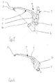
- a target device 1 can be seen, which consists essentially of a guide arm 3 and a goal hook 5 attached thereto.
- the guide arm 3 has a receptacle 4, which has a hollow cylindrical shape has and in which the housing of a drilling tool 2 are used can.
- the drilling tool 2 is during the introduction of a hole in a Bone (Fig. 4) axially displaced in the direction of the bone.
- a toothing arranged with one in the receptacle 4 arranged pawl cooperates.
- the pawl is with a Preloaded spring. This allows the drilling tool step by step be moved distally in the receptacle 4, with a reset of the tool is prevented by the toothing in the return direction vertical flanks, where the pawl blocking will get to the plant.
- the guide arm 3 of the target device 1 is arc-shaped and has an angle scale indicating the angle at which the target hook 5 for Axis 10 of the drilling tool 2 is set.
- a clamping eccentric 7 At one end of the guide track 17 is arranged, the can be adjusted by a rotatable locking knob 6.
- the target hook 5 can be moved on the guide arm 3 or from This can be easily lifted by hand. If the locking knob 6 to pivoted a certain angle, then the target hook 5 due of the clamping eccentric 7 on the guide arm 3 exerted Pressure of the guideway 17 set.
- the locking knob 6, as can be seen Fig. 3, either in Turned clockwise or counter to this sense of rotation.
- Fig. 3 is the locking knob 6 is shown in solid lines in a position A, in which the guide arm 3 and target hook 5 firmly together by traction are connected.
- the clamping position A of the locking knob is 6th as shown in FIG. 3 so that during the operation no accidental twisting the locking knob 6 is possible.
- the position of the locking knob 6, in which the target hook 5 are removed from the guide arm 3 by lifting can, is designated in Fig. 3 with B.
- Fig. 4 can be seen how the distal side End of the goal hook 5 with a later described cutting edge abuts the bone surface.
- the target hook 5 at its distal end an annular or cylindrical passage part 8, which in the End of the target hook 5 is formed.
- the passage part 8, the outside has substantially the shape of a cylinder over half the circumference over the remaining circumference it is with the end of the goal hook 5 integrally connected - has a through hole 8a for the drilling tool with an axis 9, which is aligned with the axis 10 of the drilling tool 2 (Fig. 1).
- a proximally for receiving 4 directed cutting edge 11 is provided, which at the proximal end of the passage part 8 is formed (Fig. 6).
- This cutting edge is used for secure attachment of the distal target hook end to the bone. From Fig. 6 It can be seen that the free and effective section of the cutting edge only on a part of a circle runs.
- the cutting edge is by an example V-shaped recess 17 divided, making two at a small distance arranged hook-shaped sharp edges 18 arise.
- the shape of the end portion 16 of the annular part 8 with the cutting edge 11th allows a hooking of the distal end of the target hook 5 directly to the tibial attachment site, e.g. B. of the anterior cruciate ligament.
- the annular, outside rounded passage part 8 at the distal end of the target hook 5 there is the advantage that the target hook atraumatically into the knee joint introduced and can be removed from it again, without causing tissue damage through the cutting edge can come.
Abstract
Description
Die Erfindung betrifft ein Zielgerät zum Positionieren eines Bohrwerkzeugs in Bezug auf einen zu schaffenden Bohrkanal, bestehend aus einem Zielhaken und einem lösbar mit diesem verbundenen Führungsarm , an dem eine Aufnahme für das Bohrwerkzeug angeordnet und eine Führungsbahn in Form einer seitlich durchgehend offenen Nut für den Führungsarm ausgebildet ist, der in der Führungsbahn verschiebbar und feststellbar istThe invention relates to a target device for positioning a drilling tool in Reference to a drilling channel to be created, consisting of a target hook and a guide arm detachably connected thereto arranged a receptacle for the drilling tool and a guideway in the form of a laterally open groove for the guide arm is formed, which is displaceable and lockable in the guideway
Solche Zielgeräte kommen bei der Rekonstruktion eines beispielweise aufgrund eines Unfalls gerissenen Bandes im Kniegelenk zur Anwendung. Insbesondere besteht für den Ersatz des vorderen Kreuzbandes mit der Quadrizepssehne mittels arthroskopischer Operation die Möglichkeit der implantatfreien Verankerung eines Teils der Quadrizepssehne. Im Rahmen dieser Operation ist es erforderlich, einen spongiösen Knochenzylinder aus der Tibia zu gewinnen, mit dem die Defektauffüllung an der Patella und die zusätzliche Transplantatverblockung in der Tibia vorgenommen werden kann. Hierzu muss zunächst ein Bohrkanal in Tibia und Femur exakt platziert geschaffen werden.Such target devices come in the reconstruction of an example due to an accident torn band in the knee joint for use. In particular, for the replacement of the anterior cruciate ligament with the Quadriceps tendon by means of arthroscopic surgery the possibility of Implant-free anchoring of a part of the quadriceps tendon. As part of This surgery requires a cancellous bone cylinder to gain the tibia, with which the defect filling at the patella and the additional transplant obstruction in the tibia be made can. To do this, first a drill canal in the tibia and femur must be exact be created placed.
Zur möglichst genauen Platzierung von Bohrkanälen werden Zielgeräte der eingangs erwähnten Art eingesetzt. Aus der US 5 968 050 ist ein solches Zielgerät bekannt. Dieses weist einen Führungsarm auf, an dem über eine entsprechende Aufnahme das Bohrwerkzeug angebracht werden kann. Zur Ausrichtung des Bohrwerkzeugs ist ein Zielhaken mit dem Führungsarm verbunden, der in einem vorab einstellbaren Winkel zum Führungsarm ausgerichtet werden kann. Der Zielhaken weist an seinem distalen Bereich eine gebogene Form mit einer scharfen Spitze auf, die dazu dient, das Ende des Zielhakens während des Bohrvorgangs am Knochen zu verankern, so dass das Zielgerät nicht abrutschen kann. Ähnliche Ausgestaltungen von Zielgeräten sind aus der US 4 672 957, 5 154720 und 5 350 3 83 und aus der EP 0 797 955 A1 bekannt.For the most accurate placement of drilling channels target devices of used at the beginning. From US 5,968,050 is such Target device known. This has a guide arm, on which a appropriate recording the drilling tool can be attached. To align the drilling tool is a goal hook with the guide arm connected at a pre-adjustable angle to the guide arm can be aligned. The target hook has at its distal area a curved shape with a sharp point that serves to make the Anchor the end of the target hook to the bone during the drilling process, so that the target device can not slip off. Similar configurations Targeting devices are known from US 4,672,957, 5,154,720 and 5,350 3 83 and EP 0 797 955 A1.
Ein Nachteil dieser Zielgeräte besteht darin, dass der in die Gelenkhöhle einzuführende gebogene Zielhaken aufgrund der scharfen Spitze Verletzungen in der Gelenkhöhle verursachen kann. Dieses Risiko kann zwar durch besonders sachgemäße Handhabung des Geräts und bei sorgfältiger Durchführung des endoskopischen Eingriffs gering gehalten, jedoch nie völlig ausgeschlossen werden.A disadvantage of these target devices is that in the joint cavity introduced curved target hook due to the sharp tip injuries in the joint cavity. Although this risk can through particularly appropriate handling of the device and with careful Performing the endoscopic intervention kept low, however never be completely excluded.
Aufgrund der gebogenen Form des Zielhakens besteht weiterhin der Nachteil, dass eine exakte Positionierung der in den Knochen einzubringenden Bohrung wegen des stets vorhandenen Versatzes zwischen der Spitze des Zielhakens und der sich im Abstand hierzu befindlichen Durchgangsbohrung für den erforderlichen Führungsdraht und den Bohrer nicht möglich ist.Due to the curved shape of the goal hook is still the Disadvantage that an exact positioning of the introduced into the bone Bore because of the always existing offset between the Tip of the aiming hook and the passage hole located at a distance therefrom for the required guidewire and drill not is possible.
Schließlich ist es bei bekannten Zielgeräten auch nachteilig, dass sie konstruktionsbedingt und aufgrund der anatomischen Gegebenheiten nach erfolgtem Einbringen der Bohrung nur sehr schwer wieder aus der Gelenkhöhle entfernt werden können, zumal eine vorausgehendes Trennen des Führungsarms vom Zielhaken wegen der beengten Platzverhältnisse nicht möglich ist. Deshalb besteht die Gefahr, dass Verletzungen auch in dieser Operationsphase auftreten können.Finally, it is also disadvantageous in known target devices that they Due to the design and anatomical conditions after the introduction of the bore is very difficult again from the Articular cavity can be removed, especially as a preliminary separation the guide arm of the target hook because of the limited space not possible. Therefore, there is a risk of injury can also occur in this phase of surgery.
Der Erfindung liegt die Aufgabe zugrunde, ein Zielgerät der beschriebenen Art so zu verbessern, dass die Gefahr ausgeschlossen wird, dass eine unerwünschte Verletzung der Gelenkhöhle stattfindet, und zwar sowohl beim Einbringen und Anlegen des Endes des Zielhakens in der Gelenkhöhle bzw. am Knochen als auch beim Entfernen des Zielhakens aus der Gelenkhöhle. Ferner soll es möglich werden, das Zielgerät exakt zu positionieren, so dass die Bohrung mit hoher Präzision in den Knochen eingebracht werden kann. Insbesondere soll es möglich sein, im Falle einer Kreuzband-Rekonstruktion den tibialen Ansatzpunkt so genau wie möglich zu setzen.The invention is based on the object, a target device of the described To improve the way so that the risk is excluded that a unwanted injury to the joint cavity takes place, both during insertion and application of the end of the target hook in the joint cavity or on the bone as well as when removing the target hook from the Joint cavity. Furthermore, it should be possible to position the target device exactly so that the bore is inserted into the bone with high precision can be. In particular, it should be possible in the case of Cruciate ligament reconstruction the tibial insertion point as accurately as possible to put.
Diese Aufgabe wird ausgehend von einem Zielgerät der gattungsgemäßen Art so gelöst, dass der Führungsarm von der einen Geräteseite her durch die Nutöffnung in die Führungsbahn eingesetzt werden kann. Hierdurch wird der besondere Vorteil erzielt, dass der Ziel-haken und der Führungsarm einfach durch seitlichen Versatz beider Teile wieder voneinander getrennt werden können, ohne dass es wie bei bekannten Zielgeräten erforderlich ist, zu diesem Zweck den Führungsarm aus der Führungsbahn bzw. Nut herausschieben zu müssen. Für die Verbindung des Zielhakens mit dem Führungsarm gilt umgekehrt gleiches, da der Führungsarm quasi als Einsatz nur von der Seite her in die Führungsbahn eingesetzt werden muß und dann in entsprechender Position festgestellt werden kann. Besonders günstig und einfach wird die Montage und Demontage des Zielgeräts, wenn die Querschnitte der Nut und des Führungsarms jeweils komplementär rechteckig sind.This object is based on a target device of the generic Kind solved so that the guide arm from the one side of the device can be inserted through the slot opening in the guideway. hereby the particular advantage is achieved that the target hook and the Guide arm simply by lateral offset of both parts again from each other can be disconnected without it as with known target devices is required, for this purpose, the guide arm from the guideway or slide out the groove. For the connection of the target hook the same applies vice versa with the guide arm, since the guide arm used as an insert only from the side into the guideway must be and then be determined in the appropriate position can. Especially cheap and easy is the assembly and disassembly of the targeting device when the cross-sections of the groove and the guide arm each complementary rectangular.
Am Zielhaken ist ein Sperrknebel mit einem Spannexzenter vorgesehen, mit dem der Führungsarm durch Verspannen in der Führungsbahn bzw. Nut festgelegt werden kann, und zwar durch Verdrehen des Sperrknebels in eine Richtung. Durch Verdrehen des Sperrknebels in entgegengesetzte Richtung kann die kraftschlüssige Verbindung wieder gelöst und der Führungsarm einfach vom Zielhaken aus dessen Führungsbahn heraus abgehoben werden.At the goal hook a Sperrknebel is provided with a clamping eccentric, with the guide arm by clamping in the guideway or groove can be set, by turning the locking knob in a direction. By turning the locking knob in the opposite direction Direction, the non-positive connection can be solved again and the Guide arm simply from the target hook out of its guideway be lifted off.
Das distale freie Ende des Zielhakens ist durch ein ringförmiges Durchgangsteil mit einer Durchgangsöffnung für das Bohrwerkzeug gebildet, wobei die Achsen für die Aufnahme des Bohrwerkzeugs und die Durchgangsöffnung fluchten. Weiterhin ist am distalen Ende des Zielhakens eine proximalwärts zur Aufnahme hin gerichtete Schneide als Ersatz für die sonst übliche scharfe Spitze vorgesehen. Diese Schneide istzweckmäßigerweise am proximalen und zur Aufnahme hin gerichteten Ende des Durchgangsteils angeordnet.The distal free end of the aiming hook is through an annular passage part formed with a passage opening for the drilling tool, wherein the axes for receiving the drilling tool and the passage opening aligned. Furthermore, at the distal end of the goal hook a Proximal to the receiving direction cutting edge as a substitute for the otherwise usual sharp tip provided. This cutting edge is convenient at the proximal and the receiving end of the passage part arranged.
Um den Führungsdraht für das Bohrwerkzeug und das Bohrwerkzeug selbst leicht in und durch die Durchgangsöffnung bringen zu können und das Bohrwerkzeug schließlich axial in der Durchgangsöffnung einwandfrei zu führen, weist diese in einem ersten distalen Abschnitt eine zylindrische Kontur auf, an die sich in einem zweiten Abschnitt eine sich proximalwärts erweiternde kegelstumpfförmige Kontur anschließt, so dass der Führungsdraht leicht in den ersten Abschnitt eingeführt werden kann und schließlich das Bohrwerkzeug im distalen Abschnitt geführt wird.To the guide wire for the drilling tool and the drilling tool itself easy to bring in and through the through hole and the Finally, drill bit axially in the through hole to properly lead, this has a cylindrical in a first distal portion Contour on which in a second section one is proximal expanding frusto-conical contour adjoins, allowing the guide wire can easily be introduced in the first section and finally the drilling tool is guided in the distal section.
Mit dem erfindungsgemäßen Zielgerät ist nicht nur eine atraumatische und damit schonende Positionierung des Endbereichs des Zielhakens in der Gelenkhöhle möglich, sondern auch die einfache Entfernung des Zielhakens aus diesem Bereich, nachdem vorab Führungsarm und Zielhaken wie beschrieben voneinander getrennt wurden, so dass der Operateur beim Entfernen des Zielhakens nicht durch den Führungsarm behindert wird und den Zielhaken kontrolliert aus der Gelenkhölle entfernen kann. Außerdem kann eine präzise Platzierung der Bohrung erfolgen, da der Endbereich des Zielhakens mit geringem radialen und axialen Abstand an der Insertionsstelle anliegt. Es wird damit insbesondere ermöglicht, dass auch hierdurch nach gesetzter Zielbohrung der Zielhaken unabhängig vom entfernten Führungsarm an Ort und Stelle entnommen werden kann.With the target device according to the invention is not only an atraumatic and thus careful positioning of the end portion of the goal hook in the Joint cavity possible, but also the easy removal of the target hook from this area, after advance guide arm and target hooks like described separately, so that the surgeon at Removing the aiming hook is not hindered by the guide arm and can control the target hooks from the Gelenkhölle removed. Furthermore Precise placement of the hole can be done as the end portion of the Targeting hook with small radial and axial distance at the insertion site is applied. It is thus made possible, in particular, that also by this after set target drilling the target hook regardless of the distant Guide arm can be removed in place.
In der Zeichnung ist ein Ausführungsbeispiel der Erfindung dargestellt. Es zeigen:
- Fig. 1
- eine perspektivische Ansicht eines Zielgeräts ohne eingesetztes Bohrwerkzeug,
- Fig. 2
- den vom Zielgerät abgenommenen Zielhaken in perspektivischer Ansicht,
- Fig. 3
- eine zu Fig. 1 analoge Darstellung, wobei das Zielgerät jedoch um 180° geschwenkt wurde,
- Fig. 4
- das Zielgerät mit eingesetztem Bohrwerkzeug in einer zum bearbeiteten Knochen ausgerichteten Position,
- Fig. 5
- den Endabschnitt des Zielhakens in perspektivischer Ansicht und
- Fig. 6
- den Schnitt A-A gemäß Fig. 5.
- Fig. 1
- a perspective view of a target device without inserted drilling tool,
- Fig. 2
- the target hook removed from the target device in perspective view,
- Fig. 3
- a representation analogous to FIG. 1, but with the target device being pivoted by 180 °,
- Fig. 4
- the target device with inserted drilling tool in a position aligned with the processed bone,
- Fig. 5
- the end portion of the Zielhakens in perspective view and
- Fig. 6
- the section AA of FIG. 5th
In den Fig. 1, 3 und 4 ist ein Zielgerät 1 zu sehen, das im Wesentlichen aus
einem Führungsarm 3 und einem daran befestigten Zielhaken 5 besteht.
Der Führungsarm 3 hat eine Aufnahme 4, die eine hohlzylindrische Gestalt
hat und in die das Gehäuse eines Bohrwerkzeugs 2 eingesetzt werden
kann.In Figs. 1, 3 and 4, a target device 1 can be seen, which consists essentially of
a
Das Bohrwerkzeug 2 wird während des Einbringens einer Bohrung in einen
Knochen (Fig. 4) axial in Richtung auf den Knochen verstellt. Dazu ist, was
nicht dargestellt ist, am zylindrischen Gehäuse des Bohrwerkzeugs 2 zumindest
über einen Teil des Umfangs, vorzugsweise über den halben
Umfang, eine Verzahnung angeordnet, die mit einer in der Aufnahme 4
angeordneten Sperrklinke zusammenwirkt. Die Sperrklinke ist mit einer
Druckfeder vorgespannt. Damit kann das Bohrwerkzeug stufenweise
distalwärts in der Aufnahme 4 verschoben werden, wobei ein Rückstellen
des Werkzeugs dadurch verhindert wird, dass die Verzahnung in Rückstellrichtung
senkrechte Flanken aufweist, an denen die Sperrklinke sperrend
zur Anlage gelangen wird. Es ist also im Betrieb des Bohrwerkzeugs nur eine
axiale Verschiebung des Bohrers in Richtung auf das distale Ende des
Zielhakens möglich, nicht jedoch in proximalwärtiger Richtung. Zum Entfernen
des Bohrwerkzeugs kann der beschriebene Sperrmechanismus von
Hand deaktiviert werden, so dass das Bohrwerkzeug samt Bohrer vom
Zielgerät abgezogen werden kann.The drilling tool 2 is during the introduction of a hole in a
Bone (Fig. 4) axially displaced in the direction of the bone. This is what
not shown, on the cylindrical housing of the drilling tool 2 at least
over a part of the circumference, preferably over half
Circumference, a toothing arranged with one in the
Der Führungsarm 3 des Zielgeräts 1 ist bogenförmig ausgebildet und weist
eine Winkelskala auf, die angibt, unter welchem Winkel der Zielhaken 5 zur
Achse 10 des Bohrwerkzeugs 2 eingestellt ist. Entsprechend der Form des
Bogens des Führungsarms 3 ist in den Zielhaken 5 eine komplementäre,
bogenförmige Führungsbahn 17 in Form einer Nut (Fig. 2) eingearbeitet. An
einem Ende der Führungsbahn 17 ist ein Spannexzenter 7 angeordnet, der
über einen drehbaren Sperrknebel 6 verstellt werden kann.The
Wenn sich der Spannexzenter 7 in der in Fig. 2 dargestellten Position befindet,
kann der Zielhaken 5 auf dem Führungsarm 3 verschoben oder von
diesem einfach von Hand abgehoben werden. Wird der Sperrknebel 6 um
einen bestimmten Winkel verschwenkt, dann wird der Zielhaken 5 aufgrund
des vom Spannexzenter 7 auf den Führungsarm 3 ausgeübten
Drucks der Führungsbahn 17 festgelegt.When the clamping eccentric 7 is in the position shown in FIG. 2,
the
Hierzu kann der Sperrknebel 6, wie es Fig. 3 zu sehen ist, wahlweise im
Uhrzeigersinn oder entgegen diesem Drehsinn gedreht werden. In Fig. 3 ist
der Sperrknebel 6 mit ausgezogenen Linien in einer Position A dargestellt,
bei der der Führungsarm 3 und Zielhaken 5 fest miteinander durch Kraftschluss
verbunden sind. In der Spannstellung A liegt der Sperrknebel 6
gemäß Fig. 3 so,dass bei der Operation kein versehentliches Verdrehen
des Sperrknebels 6 möglich ist. Die Position des Sperrknebels 6, in welcher
der Zielhaken 5 vom Führungsarm 3 durch Abheben abgenommen werden
kann, ist in Fig. 3 mit B bezeichnet. In Fig. 4 ist zu sehen, wie das distalseitige
Ende des Zielhakens 5 mit einer später noch beschriebenen Schneide
an der Knochenoberfläche anliegt.For this purpose, the locking
Zum präzisen Festlegen des mittels des Bohrwerkzeugs 2 in den Knochen
einzubringenden Bohrkanals weist der Zielhaken 5 an seinem distalen Ende
ein ringförmiges oder zylinderförmiges Durchgangsteil 8 auf, das in das
Ende des Zielhakens 5 eingeformt ist. Das Durchgangsteil 8, das äußerlich
über den halben Umfang im Wesentlichen die Form eines Zylinders aufweist
- über den restlichen Umfang ist es mit dem Ende des Zielhakens 5
integral verbunden - hat eine Durchgangsöffnung 8a für das Bohrwerkzeug
mit einer Achse 9, die mit der Achse 10 des Bohrwerkzeugs 2 fluchtet
(Fig. 1).For precise fixing of the means of the drilling tool 2 in the bone
to be introduced drilling channel, the
Details der Ausgestaltung des distalen Zielhakenendes ergeben sich aus
den Fig. 5 und 6. Während die Außenkontur des Durchgangsteils 8 weitgehend
zylindrisch ist, besteht der innere Durchgang dieses Teils aus einem
halbkegelstumpfförmigen Abschnitt 14 und einem halbzylinderförmigen
Abschnitt 12, deren Mantelflächen 13 fließend ineinander übergehen.Details of the configuration of the distal Zielhakenendes arise
Figs. 5 and 6. While the outer contour of the
Im distalen freien Ende des Zielhakens 5 ist eine proximalwärts zur Aufnahme
4 hin gerichtete Schneide 11 vorgesehen, die am proximalen Ende
des Durchgangsteils 8 ausgebildet ist (Fig. 6). Diese Schneide dient zur
sicheren Anlage des distalen Zielhakenendes am Knochen. Aus der Fig. 6
ist ersichtlich, dass der freie und wirksame Abschnitt der Schneide nur auf
einem Teil eines Kreises verläuft.In the distal free end of the
Um ein Abgleiten der Schneide 11 bzw. Schneidkante vom Knochen
besonders wirksam zu verhindern, ist die Schneide durch eine beispielsweise
V-förmige Ausnehmung 17 geteilt, wodurch zwei im geringen Abstand
zueinander angeordnete hakenförmige scharfe Kanten 18 entstehen.To a sliding of the
Im Vergleich mit bekannten Ausgestaltungen des distalen Zielhakenendes
mit einer Hakenspitze ergibt sich, dass bei der erfindungsgemäßen Ausführung
nur ein kleiner radialer Abstand zwischen dem Anlagepunkt der
Schneide 11 am Knochen und der Achse 10 des Bohrwerkzeugs 2 gegeben
ist. Dies ermöglicht eine wesentlich exaktere Positionierung der Bohrung
als mit herkömmlichen Zielgeräten. In comparison with known embodiments of the distal Zielhakenendes
with a hook tip it follows that in the embodiment according to the invention
only a small radial distance between the contact point of
Cutting
Die Form des Endbereichs 16 des ringförmigen Teils 8 mit der Schneide 11
ermöglicht ein Einhaken des distalen Endes des Zielhakens 5 direkt an der
tibialen Ansatzstelle, z. B. des vorderen Kreuzbandes. Durch das ringförmige,
außen abgerundete Durchgangsteil 8 am distalen Ende des Zielhakens
5 ergibt sich der Vorteil, dass der Zielhaken atraumatisch in das Kniegelenk
eingeführt und auch wieder aus diesem entfernt werden kann,
ohne dass es dabei zu Verletzungen von Gewebe durch die Schneide
kommen kann.The shape of the
Claims (8)
Applications Claiming Priority (2)
| Application Number | Priority Date | Filing Date | Title |
|---|---|---|---|
| DE10146452 | 2001-09-20 | ||
| DE10146452A DE10146452B4 (en) | 2001-09-20 | 2001-09-20 | target device |
Publications (2)
| Publication Number | Publication Date |
|---|---|
| EP1297790A1 true EP1297790A1 (en) | 2003-04-02 |
| EP1297790B1 EP1297790B1 (en) | 2004-10-20 |
Family
ID=7699720
Family Applications (1)
| Application Number | Title | Priority Date | Filing Date |
|---|---|---|---|
| EP02020708A Expired - Lifetime EP1297790B1 (en) | 2001-09-20 | 2002-09-14 | Surgical drillguide |
Country Status (4)
| Country | Link |
|---|---|
| US (1) | US6918916B2 (en) |
| EP (1) | EP1297790B1 (en) |
| AT (1) | ATE279885T1 (en) |
| DE (2) | DE10146452B4 (en) |
Cited By (1)
| Publication number | Priority date | Publication date | Assignee | Title |
|---|---|---|---|---|
| WO2010029409A1 (en) * | 2008-09-10 | 2010-03-18 | University Of Cape Town | A surgical drill aimer |
Families Citing this family (31)
| Publication number | Priority date | Publication date | Assignee | Title |
|---|---|---|---|---|
| US20050049602A1 (en) * | 2001-09-27 | 2005-03-03 | Matthias Honl | Surgical instruments |
| US7131974B2 (en) * | 2003-10-14 | 2006-11-07 | Keyer Thomas R | Surgical drill guide |
| US9770344B2 (en) * | 2006-03-23 | 2017-09-26 | Imperial Innovations Ltd. | Reconstruction of anterior cruciate ligaments |
| GB0605817D0 (en) * | 2006-03-23 | 2006-05-03 | Imp Innovations Ltd | Reconstruction of anterior cruciate ligaments |
| DE102007057075A1 (en) * | 2007-11-23 | 2009-05-28 | Karl Storz Gmbh & Co. Kg | Tibial target device for the dual channel technique |
| US9826992B2 (en) * | 2007-12-21 | 2017-11-28 | Smith & Nephew, Inc. | Multiple portal guide |
| AU2009222580B2 (en) * | 2008-10-10 | 2014-11-27 | Depuy Mitek, Inc. | Method for replacing a ligament in a knee |
| WO2011063279A1 (en) | 2009-11-19 | 2011-05-26 | Knee Creations, Llc | Coordinate mapping system for joint treatment |
| WO2011063257A1 (en) * | 2009-11-20 | 2011-05-26 | Knee Creations, Llc | Instruments for targeting a joint defect |
| WO2011063260A1 (en) | 2009-11-20 | 2011-05-26 | Knee Creations, Llc | Bone-derived implantable devices for subchondral treatment of joint pain |
| US8951261B2 (en) | 2009-11-20 | 2015-02-10 | Zimmer Knee Creations, Inc. | Subchondral treatment of joint pain |
| US8608802B2 (en) | 2009-11-20 | 2013-12-17 | Zimmer Knee Creations, Inc. | Implantable devices for subchondral treatment of joint pain |
| US8821504B2 (en) | 2009-11-20 | 2014-09-02 | Zimmer Knee Creations, Inc. | Method for treating joint pain and associated instruments |
| JP2013511358A (en) | 2009-11-20 | 2013-04-04 | ニー・クリエイションズ・リミテッド・ライアビリティ・カンパニー | Navigation and positioning equipment for joint repair |
| DE102010024259B4 (en) | 2010-06-18 | 2012-12-13 | Richard Wolf Gmbh | Surgical target device for cruciate ligament reconstruction |
| KR20150023200A (en) | 2010-09-27 | 2015-03-05 | 스미스 앤드 네퓨, 인크. | Device and methods for use during arthroscopic surgery |
| DE102010046948A1 (en) | 2010-09-29 | 2011-12-08 | Richard Wolf Gmbh | Surgical target device for positioning e.g. tibial drilling channel in knee joint at tibial plateau, has markers or sensors arranged at guide arm to detect position of target device, and drill guide displaced along guide arm |
| US8617168B2 (en) * | 2010-10-25 | 2013-12-31 | Smith & Nephew, Inc. | Oval tibia guide |
| US10219812B2 (en) | 2010-11-03 | 2019-03-05 | Smith & Nephew, Inc. | Drill guide |
| US9198676B2 (en) | 2011-07-26 | 2015-12-01 | Howmedica Osteonics Corp. | PCL guides for drilling tibial and femoral tunnels |
| US8617176B2 (en) * | 2011-08-24 | 2013-12-31 | Depuy Mitek, Llc | Cross pinning guide devices and methods |
| WO2015171761A1 (en) * | 2014-05-08 | 2015-11-12 | Smith & Nephew, Inc. | Methods and devices for attaching or reattaching soft tissue to bone |
| US10045789B2 (en) * | 2014-09-30 | 2018-08-14 | Medos International Sàrl | Universal surgical guide systems and methods |
| US10098646B2 (en) | 2014-09-30 | 2018-10-16 | Medos International Sàrl | Surgical guide for use in ligament repair procedures |
| US10010333B2 (en) | 2014-09-30 | 2018-07-03 | Medos International Sàrl | Side-loading carriage for use in surgical guide |
| US10307173B2 (en) | 2014-09-30 | 2019-06-04 | Medos International Sàrl | Gage for limiting distal travel of drill pin |
| USD761960S1 (en) | 2014-11-07 | 2016-07-19 | Karl Storz Gmbh & Co. Kg | Aiming device |
| DE102016103642A1 (en) | 2016-03-01 | 2017-09-07 | Karl Storz Gmbh & Co. Kg | Targeting device for aligning a surgical drilling instrument |
| CN209851112U (en) * | 2017-10-16 | 2019-12-27 | 创科(澳门离岸商业服务)有限公司 | Inclined hole clamp |
| US11357521B2 (en) * | 2019-02-18 | 2022-06-14 | Conmed Corporation | Multifunctional PCL guide arm |
| DE102019114352B4 (en) | 2019-05-28 | 2022-02-24 | Karl Storz Se & Co. Kg | positioning system |
Citations (2)
| Publication number | Priority date | Publication date | Assignee | Title |
|---|---|---|---|---|
| US5891150A (en) * | 1996-12-04 | 1999-04-06 | Chan; Kwan-Ho | Apparatus and method for fixing a ligament in a bone tunnel |
| US5968050A (en) * | 1997-12-05 | 1999-10-19 | Smith & Nephew, Inc. | Positioning a tibial tunnel |
Family Cites Families (10)
| Publication number | Priority date | Publication date | Assignee | Title |
|---|---|---|---|---|
| US4672957A (en) * | 1983-10-04 | 1987-06-16 | South African Inventions Development Corporation | Surgical device |
| US5154720A (en) * | 1992-02-19 | 1992-10-13 | Linvatec Corporation | Surgical drill guide |
| US5350383A (en) * | 1992-02-20 | 1994-09-27 | Arthrex, Inc. | Adjustable drill guide with interchangeable marking hooks |
| US5562664A (en) * | 1992-02-20 | 1996-10-08 | Arthrex Inc. | Drill guide with target PCL-oriented marking hook |
| US5458602A (en) * | 1994-01-11 | 1995-10-17 | Mitek Surgical Products, Inc. | Surgical drill guide |
| US5667509A (en) * | 1995-03-02 | 1997-09-16 | Westin; Craig D. | Retractable shield apparatus and method for a bone drill |
| GB9606525D0 (en) * | 1996-03-28 | 1996-06-05 | United Surgical Services Ltd | Surgical instrument |
| US5688284A (en) * | 1996-09-20 | 1997-11-18 | Medicinelodge, Inc. | Variable angle drill guide and ligament fixation method |
| US6120511A (en) * | 1997-11-18 | 2000-09-19 | Chan; Kwan-Ho | Drill guide assembly and method for producing a bone tunnel |
| US6254606B1 (en) * | 1999-10-13 | 2001-07-03 | William P. Carney | Laser aiming device for performing anterior cruciate ligament reconstruction surgery and method for using same |
-
2001
- 2001-09-20 DE DE10146452A patent/DE10146452B4/en not_active Expired - Fee Related
-
2002
- 2002-09-14 EP EP02020708A patent/EP1297790B1/en not_active Expired - Lifetime
- 2002-09-14 AT AT02020708T patent/ATE279885T1/en active
- 2002-09-14 DE DE50201339T patent/DE50201339D1/en not_active Expired - Lifetime
- 2002-09-20 US US10/247,975 patent/US6918916B2/en not_active Expired - Fee Related
Patent Citations (2)
| Publication number | Priority date | Publication date | Assignee | Title |
|---|---|---|---|---|
| US5891150A (en) * | 1996-12-04 | 1999-04-06 | Chan; Kwan-Ho | Apparatus and method for fixing a ligament in a bone tunnel |
| US5968050A (en) * | 1997-12-05 | 1999-10-19 | Smith & Nephew, Inc. | Positioning a tibial tunnel |
Cited By (1)
| Publication number | Priority date | Publication date | Assignee | Title |
|---|---|---|---|---|
| WO2010029409A1 (en) * | 2008-09-10 | 2010-03-18 | University Of Cape Town | A surgical drill aimer |
Also Published As
| Publication number | Publication date |
|---|---|
| DE10146452B4 (en) | 2004-01-15 |
| US20030051591A1 (en) | 2003-03-20 |
| DE10146452A1 (en) | 2003-04-17 |
| US6918916B2 (en) | 2005-07-19 |
| EP1297790B1 (en) | 2004-10-20 |
| DE50201339D1 (en) | 2004-11-25 |
| ATE279885T1 (en) | 2004-11-15 |
Similar Documents
| Publication | Publication Date | Title |
|---|---|---|
| EP1297790B1 (en) | Surgical drillguide | |
| DE102006062382B4 (en) | Device for guiding a drilling tool for introducing a second bore in a bone | |
| EP0998883B1 (en) | Implantation tool for a cruciate ligament in a knee joint | |
| DE69819567T2 (en) | Orthopedic cut and sleeve | |
| DE69823030T2 (en) | FREE SEPARABLE SURGICAL PIPE AND PLATE | |
| DE3231838C2 (en) | ||
| DE102004051794B4 (en) | Coupling system for a medical dissecting tool | |
| EP1642538B1 (en) | Device for guiding a drilling tool | |
| DE4306277C2 (en) | Operation marking tool | |
| EP1714619B1 (en) | Instrument for making a bore in a bone | |
| EP1725177B1 (en) | Resetting tool | |
| EP2432402B1 (en) | Device for introducing a bent nail into a bone | |
| DE3407084A1 (en) | DEVICE FOR SETTING SURGICAL CLASPS | |
| WO2009152919A1 (en) | Device for removing bone tissue during endoscopic surgery | |
| WO2002009596A1 (en) | Device for aligning a guide template | |
| EP1732466B1 (en) | Instrument for fixing an implant in a bone | |
| EP2497432A1 (en) | Medicinal grooving tool | |
| EP2468216B1 (en) | Implantable prosthesis for replacing human hip or knee joints and the adjoining bone sections | |
| EP1601293B1 (en) | Medical equipment for creating a surgical space for oral surgery | |
| DE3912753A1 (en) | Thigh part of a hip joint endoprosthesis | |
| EP1587434A1 (en) | Medical instrument for dissecting tissue | |
| DE102007016459B4 (en) | implant set | |
| DE202011000553U1 (en) | Surgical aiming device and intramedullary splinting system for long bones with medullary canal | |
| DE202007005061U1 (en) | implant set | |
| DE102005027866B4 (en) | Medical instrument for operations in the region of a spinal column |
Legal Events
| Date | Code | Title | Description |
|---|---|---|---|
| PUAI | Public reference made under article 153(3) epc to a published international application that has entered the european phase |
Free format text: ORIGINAL CODE: 0009012 |
|
| AK | Designated contracting states |
Kind code of ref document: A1 Designated state(s): AT BE BG CH CY CZ DE DK EE ES FI FR GB GR IE IT LI LU MC NL PT SE SK TR Designated state(s): AT BE BG CH CY CZ DE DK EE ES FI FR GB GR IE IT LI LU MC NL PT SE SK TR |
|
| AX | Request for extension of the european patent |
Extension state: AL LT LV MK RO SI |
|
| 17P | Request for examination filed |
Effective date: 20030807 |
|
| GRAP | Despatch of communication of intention to grant a patent |
Free format text: ORIGINAL CODE: EPIDOSNIGR1 |
|
| AKX | Designation fees paid |
Designated state(s): AT BE BG CH CY CZ DE DK EE ES FI FR GB GR IE IT LI LU MC NL PT SE SK TR |
|
| GRAS | Grant fee paid |
Free format text: ORIGINAL CODE: EPIDOSNIGR3 |
|
| GRAA | (expected) grant |
Free format text: ORIGINAL CODE: 0009210 |
|
| AK | Designated contracting states |
Kind code of ref document: B1 Designated state(s): AT BE BG CH CY CZ DE DK EE ES FI FR GB GR IE IT LI LU MC NL PT SE SK TR |
|
| PG25 | Lapsed in a contracting state [announced via postgrant information from national office to epo] |
Ref country code: CZ Free format text: LAPSE BECAUSE OF FAILURE TO SUBMIT A TRANSLATION OF THE DESCRIPTION OR TO PAY THE FEE WITHIN THE PRESCRIBED TIME-LIMIT Effective date: 20041020 Ref country code: BG Free format text: LAPSE BECAUSE OF FAILURE TO SUBMIT A TRANSLATION OF THE DESCRIPTION OR TO PAY THE FEE WITHIN THE PRESCRIBED TIME-LIMIT Effective date: 20041020 Ref country code: TR Free format text: LAPSE BECAUSE OF FAILURE TO SUBMIT A TRANSLATION OF THE DESCRIPTION OR TO PAY THE FEE WITHIN THE PRESCRIBED TIME-LIMIT Effective date: 20041020 Ref country code: EE Free format text: LAPSE BECAUSE OF FAILURE TO SUBMIT A TRANSLATION OF THE DESCRIPTION OR TO PAY THE FEE WITHIN THE PRESCRIBED TIME-LIMIT Effective date: 20041020 Ref country code: SK Free format text: LAPSE BECAUSE OF FAILURE TO SUBMIT A TRANSLATION OF THE DESCRIPTION OR TO PAY THE FEE WITHIN THE PRESCRIBED TIME-LIMIT Effective date: 20041020 Ref country code: NL Free format text: LAPSE BECAUSE OF FAILURE TO SUBMIT A TRANSLATION OF THE DESCRIPTION OR TO PAY THE FEE WITHIN THE PRESCRIBED TIME-LIMIT Effective date: 20041020 Ref country code: FI Free format text: LAPSE BECAUSE OF FAILURE TO SUBMIT A TRANSLATION OF THE DESCRIPTION OR TO PAY THE FEE WITHIN THE PRESCRIBED TIME-LIMIT Effective date: 20041020 |
|
| REG | Reference to a national code |
Ref country code: GB Ref legal event code: FG4D Free format text: NOT ENGLISH |
|
| REG | Reference to a national code |
Ref country code: CH Ref legal event code: EP |
|
| REG | Reference to a national code |
Ref country code: IE Ref legal event code: FG4D Free format text: GERMAN |
|
| REF | Corresponds to: |
Ref document number: 50201339 Country of ref document: DE Date of ref document: 20041125 Kind code of ref document: P |
|
| GBT | Gb: translation of ep patent filed (gb section 77(6)(a)/1977) |
Effective date: 20041222 |
|
| PG25 | Lapsed in a contracting state [announced via postgrant information from national office to epo] |
Ref country code: GR Free format text: LAPSE BECAUSE OF FAILURE TO SUBMIT A TRANSLATION OF THE DESCRIPTION OR TO PAY THE FEE WITHIN THE PRESCRIBED TIME-LIMIT Effective date: 20050120 Ref country code: DK Free format text: LAPSE BECAUSE OF FAILURE TO SUBMIT A TRANSLATION OF THE DESCRIPTION OR TO PAY THE FEE WITHIN THE PRESCRIBED TIME-LIMIT Effective date: 20050120 Ref country code: SE Free format text: LAPSE BECAUSE OF FAILURE TO SUBMIT A TRANSLATION OF THE DESCRIPTION OR TO PAY THE FEE WITHIN THE PRESCRIBED TIME-LIMIT Effective date: 20050120 |
|
| PG25 | Lapsed in a contracting state [announced via postgrant information from national office to epo] |
Ref country code: ES Free format text: LAPSE BECAUSE OF FAILURE TO SUBMIT A TRANSLATION OF THE DESCRIPTION OR TO PAY THE FEE WITHIN THE PRESCRIBED TIME-LIMIT Effective date: 20050131 |
|
| NLV1 | Nl: lapsed or annulled due to failure to fulfill the requirements of art. 29p and 29m of the patents act | ||
| PLBE | No opposition filed within time limit |
Free format text: ORIGINAL CODE: 0009261 |
|
| STAA | Information on the status of an ep patent application or granted ep patent |
Free format text: STATUS: NO OPPOSITION FILED WITHIN TIME LIMIT |
|
| PG25 | Lapsed in a contracting state [announced via postgrant information from national office to epo] |
Ref country code: CY Free format text: LAPSE BECAUSE OF FAILURE TO SUBMIT A TRANSLATION OF THE DESCRIPTION OR TO PAY THE FEE WITHIN THE PRESCRIBED TIME-LIMIT Effective date: 20050914 |
|
| ET | Fr: translation filed | ||
| PG25 | Lapsed in a contracting state [announced via postgrant information from national office to epo] |
Ref country code: MC Free format text: LAPSE BECAUSE OF NON-PAYMENT OF DUE FEES Effective date: 20050930 Ref country code: BE Free format text: LAPSE BECAUSE OF NON-PAYMENT OF DUE FEES Effective date: 20050930 Ref country code: LU Free format text: LAPSE BECAUSE OF NON-PAYMENT OF DUE FEES Effective date: 20050930 |
|
| 26N | No opposition filed |
Effective date: 20050721 |
|
| PG25 | Lapsed in a contracting state [announced via postgrant information from national office to epo] |
Ref country code: CH Free format text: LAPSE BECAUSE OF NON-PAYMENT OF DUE FEES Effective date: 20060930 Ref country code: LI Free format text: LAPSE BECAUSE OF NON-PAYMENT OF DUE FEES Effective date: 20060930 |
|
| REG | Reference to a national code |
Ref country code: CH Ref legal event code: PL |
|
| BERE | Be: lapsed |
Owner name: RICHARD *WOLF G.M.B.H. Effective date: 20050930 |
|
| PG25 | Lapsed in a contracting state [announced via postgrant information from national office to epo] |
Ref country code: PT Free format text: LAPSE BECAUSE OF NON-PAYMENT OF DUE FEES Effective date: 20050320 |
|
| REG | Reference to a national code |
Ref country code: FR Ref legal event code: PLFP Year of fee payment: 15 |
|
| REG | Reference to a national code |
Ref country code: FR Ref legal event code: PLFP Year of fee payment: 16 |
|
| REG | Reference to a national code |
Ref country code: FR Ref legal event code: PLFP Year of fee payment: 17 |
|
| PGFP | Annual fee paid to national office [announced via postgrant information from national office to epo] |
Ref country code: IT Payment date: 20190920 Year of fee payment: 18 Ref country code: FR Payment date: 20190923 Year of fee payment: 18 Ref country code: IE Payment date: 20190918 Year of fee payment: 18 |
|
| PGFP | Annual fee paid to national office [announced via postgrant information from national office to epo] |
Ref country code: AT Payment date: 20190918 Year of fee payment: 18 Ref country code: GB Payment date: 20190924 Year of fee payment: 18 |
|
| REG | Reference to a national code |
Ref country code: DE Ref legal event code: R084 Ref document number: 50201339 Country of ref document: DE |
|
| PGFP | Annual fee paid to national office [announced via postgrant information from national office to epo] |
Ref country code: DE Payment date: 20200928 Year of fee payment: 19 |
|
| REG | Reference to a national code |
Ref country code: AT Ref legal event code: MM01 Ref document number: 279885 Country of ref document: AT Kind code of ref document: T Effective date: 20200914 |
|
| GBPC | Gb: european patent ceased through non-payment of renewal fee |
Effective date: 20200914 |
|
| PG25 | Lapsed in a contracting state [announced via postgrant information from national office to epo] |
Ref country code: FR Free format text: LAPSE BECAUSE OF NON-PAYMENT OF DUE FEES Effective date: 20200930 |
|
| PG25 | Lapsed in a contracting state [announced via postgrant information from national office to epo] |
Ref country code: AT Free format text: LAPSE BECAUSE OF NON-PAYMENT OF DUE FEES Effective date: 20200914 Ref country code: GB Free format text: LAPSE BECAUSE OF NON-PAYMENT OF DUE FEES Effective date: 20200914 Ref country code: IE Free format text: LAPSE BECAUSE OF NON-PAYMENT OF DUE FEES Effective date: 20200914 |
|
| REG | Reference to a national code |
Ref country code: DE Ref legal event code: R119 Ref document number: 50201339 Country of ref document: DE |
|
| PG25 | Lapsed in a contracting state [announced via postgrant information from national office to epo] |
Ref country code: IT Free format text: LAPSE BECAUSE OF NON-PAYMENT OF DUE FEES Effective date: 20200914 |
|
| PG25 | Lapsed in a contracting state [announced via postgrant information from national office to epo] |
Ref country code: DE Free format text: LAPSE BECAUSE OF NON-PAYMENT OF DUE FEES Effective date: 20220401 |