EP1296412A2 - Parking aid device for motor vehicles - Google Patents
Parking aid device for motor vehicles Download PDFInfo
- Publication number
- EP1296412A2 EP1296412A2 EP02014501A EP02014501A EP1296412A2 EP 1296412 A2 EP1296412 A2 EP 1296412A2 EP 02014501 A EP02014501 A EP 02014501A EP 02014501 A EP02014501 A EP 02014501A EP 1296412 A2 EP1296412 A2 EP 1296412A2
- Authority
- EP
- European Patent Office
- Prior art keywords
- vehicle
- sensors
- sensor
- distance
- transmission signal
- Prior art date
- Legal status (The legal status is an assumption and is not a legal conclusion. Google has not performed a legal analysis and makes no representation as to the accuracy of the status listed.)
- Granted
Links
Images

Classifications
-
- B—PERFORMING OPERATIONS; TRANSPORTING
- B60—VEHICLES IN GENERAL
- B60Q—ARRANGEMENT OF SIGNALLING OR LIGHTING DEVICES, THE MOUNTING OR SUPPORTING THEREOF OR CIRCUITS THEREFOR, FOR VEHICLES IN GENERAL
- B60Q9/00—Arrangement or adaptation of signal devices not provided for in one of main groups B60Q1/00 - B60Q7/00, e.g. haptic signalling
- B60Q9/002—Arrangement or adaptation of signal devices not provided for in one of main groups B60Q1/00 - B60Q7/00, e.g. haptic signalling for parking purposes, e.g. for warning the driver that his vehicle has contacted or is about to contact an obstacle
- B60Q9/004—Arrangement or adaptation of signal devices not provided for in one of main groups B60Q1/00 - B60Q7/00, e.g. haptic signalling for parking purposes, e.g. for warning the driver that his vehicle has contacted or is about to contact an obstacle using wave sensors
- B60Q9/006—Arrangement or adaptation of signal devices not provided for in one of main groups B60Q1/00 - B60Q7/00, e.g. haptic signalling for parking purposes, e.g. for warning the driver that his vehicle has contacted or is about to contact an obstacle using wave sensors using a distance sensor
-
- G—PHYSICS
- G01—MEASURING; TESTING
- G01S—RADIO DIRECTION-FINDING; RADIO NAVIGATION; DETERMINING DISTANCE OR VELOCITY BY USE OF RADIO WAVES; LOCATING OR PRESENCE-DETECTING BY USE OF THE REFLECTION OR RERADIATION OF RADIO WAVES; ANALOGOUS ARRANGEMENTS USING OTHER WAVES
- G01S13/00—Systems using the reflection or reradiation of radio waves, e.g. radar systems; Analogous systems using reflection or reradiation of waves whose nature or wavelength is irrelevant or unspecified
- G01S13/88—Radar or analogous systems specially adapted for specific applications
- G01S13/93—Radar or analogous systems specially adapted for specific applications for anti-collision purposes
- G01S13/931—Radar or analogous systems specially adapted for specific applications for anti-collision purposes of land vehicles
-
- H—ELECTRICITY
- H01—ELECTRIC ELEMENTS
- H01Q—ANTENNAS, i.e. RADIO AERIALS
- H01Q1/00—Details of, or arrangements associated with, antennas
- H01Q1/27—Adaptation for use in or on movable bodies
- H01Q1/32—Adaptation for use in or on road or rail vehicles
- H01Q1/3208—Adaptation for use in or on road or rail vehicles characterised by the application wherein the antenna is used
- H01Q1/3233—Adaptation for use in or on road or rail vehicles characterised by the application wherein the antenna is used particular used as part of a sensor or in a security system, e.g. for automotive radar, navigation systems
-
- H—ELECTRICITY
- H01—ELECTRIC ELEMENTS
- H01Q—ANTENNAS, i.e. RADIO AERIALS
- H01Q1/00—Details of, or arrangements associated with, antennas
- H01Q1/27—Adaptation for use in or on movable bodies
- H01Q1/32—Adaptation for use in or on road or rail vehicles
- H01Q1/325—Adaptation for use in or on road or rail vehicles characterised by the location of the antenna on the vehicle
- H01Q1/3283—Adaptation for use in or on road or rail vehicles characterised by the location of the antenna on the vehicle side-mounted antennas, e.g. bumper-mounted, door-mounted
-
- G—PHYSICS
- G01—MEASURING; TESTING
- G01S—RADIO DIRECTION-FINDING; RADIO NAVIGATION; DETERMINING DISTANCE OR VELOCITY BY USE OF RADIO WAVES; LOCATING OR PRESENCE-DETECTING BY USE OF THE REFLECTION OR RERADIATION OF RADIO WAVES; ANALOGOUS ARRANGEMENTS USING OTHER WAVES
- G01S13/00—Systems using the reflection or reradiation of radio waves, e.g. radar systems; Analogous systems using reflection or reradiation of waves whose nature or wavelength is irrelevant or unspecified
- G01S13/88—Radar or analogous systems specially adapted for specific applications
- G01S13/93—Radar or analogous systems specially adapted for specific applications for anti-collision purposes
- G01S13/931—Radar or analogous systems specially adapted for specific applications for anti-collision purposes of land vehicles
- G01S2013/9314—Parking operations
-
- G—PHYSICS
- G01—MEASURING; TESTING
- G01S—RADIO DIRECTION-FINDING; RADIO NAVIGATION; DETERMINING DISTANCE OR VELOCITY BY USE OF RADIO WAVES; LOCATING OR PRESENCE-DETECTING BY USE OF THE REFLECTION OR RERADIATION OF RADIO WAVES; ANALOGOUS ARRANGEMENTS USING OTHER WAVES
- G01S13/00—Systems using the reflection or reradiation of radio waves, e.g. radar systems; Analogous systems using reflection or reradiation of waves whose nature or wavelength is irrelevant or unspecified
- G01S13/88—Radar or analogous systems specially adapted for specific applications
- G01S13/93—Radar or analogous systems specially adapted for specific applications for anti-collision purposes
- G01S13/931—Radar or analogous systems specially adapted for specific applications for anti-collision purposes of land vehicles
- G01S2013/9324—Alternative operation using ultrasonic waves
-
- G—PHYSICS
- G01—MEASURING; TESTING
- G01S—RADIO DIRECTION-FINDING; RADIO NAVIGATION; DETERMINING DISTANCE OR VELOCITY BY USE OF RADIO WAVES; LOCATING OR PRESENCE-DETECTING BY USE OF THE REFLECTION OR RERADIATION OF RADIO WAVES; ANALOGOUS ARRANGEMENTS USING OTHER WAVES
- G01S13/00—Systems using the reflection or reradiation of radio waves, e.g. radar systems; Analogous systems using reflection or reradiation of waves whose nature or wavelength is irrelevant or unspecified
- G01S13/88—Radar or analogous systems specially adapted for specific applications
- G01S13/93—Radar or analogous systems specially adapted for specific applications for anti-collision purposes
- G01S13/931—Radar or analogous systems specially adapted for specific applications for anti-collision purposes of land vehicles
- G01S2013/9327—Sensor installation details
- G01S2013/93274—Sensor installation details on the side of the vehicles
-
- G—PHYSICS
- G01—MEASURING; TESTING
- G01S—RADIO DIRECTION-FINDING; RADIO NAVIGATION; DETERMINING DISTANCE OR VELOCITY BY USE OF RADIO WAVES; LOCATING OR PRESENCE-DETECTING BY USE OF THE REFLECTION OR RERADIATION OF RADIO WAVES; ANALOGOUS ARRANGEMENTS USING OTHER WAVES
- G01S15/00—Systems using the reflection or reradiation of acoustic waves, e.g. sonar systems
- G01S15/88—Sonar systems specially adapted for specific applications
- G01S15/93—Sonar systems specially adapted for specific applications for anti-collision purposes
- G01S15/931—Sonar systems specially adapted for specific applications for anti-collision purposes of land vehicles
- G01S2015/932—Sonar systems specially adapted for specific applications for anti-collision purposes of land vehicles for parking operations
- G01S2015/933—Sonar systems specially adapted for specific applications for anti-collision purposes of land vehicles for parking operations for measuring the dimensions of the parking space when driving past
- G01S2015/934—Sonar systems specially adapted for specific applications for anti-collision purposes of land vehicles for parking operations for measuring the dimensions of the parking space when driving past for measuring the depth, i.e. width, not length, of the parking space
-
- G—PHYSICS
- G01—MEASURING; TESTING
- G01S—RADIO DIRECTION-FINDING; RADIO NAVIGATION; DETERMINING DISTANCE OR VELOCITY BY USE OF RADIO WAVES; LOCATING OR PRESENCE-DETECTING BY USE OF THE REFLECTION OR RERADIATION OF RADIO WAVES; ANALOGOUS ARRANGEMENTS USING OTHER WAVES
- G01S15/00—Systems using the reflection or reradiation of acoustic waves, e.g. sonar systems
- G01S15/88—Sonar systems specially adapted for specific applications
- G01S15/93—Sonar systems specially adapted for specific applications for anti-collision purposes
- G01S15/931—Sonar systems specially adapted for specific applications for anti-collision purposes of land vehicles
- G01S2015/932—Sonar systems specially adapted for specific applications for anti-collision purposes of land vehicles for parking operations
- G01S2015/933—Sonar systems specially adapted for specific applications for anti-collision purposes of land vehicles for parking operations for measuring the dimensions of the parking space when driving past
- G01S2015/935—Sonar systems specially adapted for specific applications for anti-collision purposes of land vehicles for parking operations for measuring the dimensions of the parking space when driving past for measuring the contour, e.g. a trajectory of measurement points, representing the boundary of the parking space
Definitions
- sensor 1 delivers almost the same object information as that Sensor 2, since the surface area of the side surface irradiated in the direction of reflection the parking space limits for the two sensors hardly differ. After passing the front there are then for both sensors practically no more surface elements in the direction of reflection, the intensity of the distance signals drops abruptly in both sensors.
Abstract
Description
Die Erfindung bezieht sich auf eine Einparkhilfsvorrichtung für Kraftfahrzeuge mit
den im Oberbegriff des Patentanspruchs 1 angegeben Merkmalen.The invention relates to a parking aid device for motor vehicles
the features specified in the preamble of
Verschiedene bekannte Einparkhilfsvorrichtungen sehen zur Vermessung von Parklücken mindestens einen an der dem Bordstein zugewandten Fahrzeugseite montierten Abstandssensor vor, welcher senkrecht zur Fahrtrichtung beim Vorbeifahren die Länge (vgl. DE 3728948 A) und optional bei tiefenbegrenzten Parklücken (z.B. durch Bordstein) auch deren Tiefe ermittelt. Als Abstandssensoren dienen dabei Ultraschall- oder Radar-Abstandsmesssysteme (z.B. 24 GHz-Systeme) mit konischen Strahlenkeulen. Aus Gründen der Antennen-Querschnittsfläche finden bei den Radarsystemen Öffnungswinkel von ca. 60° Anwendung, bei den kostengünstigeren Ultraschallsystemen kommen auch kleinere Winkel in Betracht. Unter Abstandssensor ist dabei eine Sender-/Empfängereinrichtung mit nachgeschalteter Auswerteelektronik zu verstehen.Various known parking aids are used to measure parking spaces at least one mounted on the side of the vehicle facing the curb Distance sensor in front, which is perpendicular to the direction of travel when driving past the length (cf. DE 3728948 A) and optionally with depth-limited parking spaces (e.g. by curb) also determined their depth. Serve as distance sensors Ultrasonic or radar distance measuring systems (e.g. 24 GHz systems) with conical Beams. For reasons of antenna cross-sectional area, see the radar systems opening angle of approx. 60 ° application, with the less expensive ones Ultrasound systems can also consider smaller angles. Under distance sensor is a transmitter / receiver device with a downstream To understand evaluation electronics.
Im Gegensatz zu Licht arbeiten die beschriebenen Abstandssensoren mit relativ grossen Wellenlängen (z.B. 12,5mm@24GHz und 8,6mm@40kHz US). Damit reflektieren bestrahlte Objekte, welche ein Rauigkeitsmass unterhalb dieser Wellenlänge aufweisen, wie ideale Spiegel.In contrast to light, the distance sensors described work with relative large wavelengths (e.g. 12.5mm @ 24GHz and 8.6mm @ 40kHz US). So reflect irradiated objects which have a roughness measure below this wavelength have, like ideal mirrors.
Da die Sensoren nur Abstands-, nicht aber Richtungsinformation liefern, müssen im Strahlkegel erfasste Objekte auf die Strahlachse positioniert werden. Die Abschätzung der Richtung mittels Triangulation bei Verwendung zweier oder mehrerer Sensoren gelingt aber nur dann, falls genau dieselbe Objektstelle anmessen wird. Dies geht aber mit spiegelartig reflektierenden Objekten prinzipiell nicht, da hier nur senkrecht auftreffende Strahlung in den Empfänger zurückreflektiert wird.Since the sensors only provide distance, but not direction information, the Beam cone detected objects are positioned on the beam axis. The estimate the direction using triangulation when using two or more sensors but only succeeds if the exact same object location is measured. This is basically not possible with mirror-like reflecting objects, since only vertical incident radiation is reflected back into the receiver.
Die Parklückenvermessung beinhaltet zwei grundsätzliche Probleme: Erstens beeinflusst die geometrische Form der Parklückenbegrenzungen (kastenförmig oder abgerundet) die Längsvermessung, zweitens kommt die Ununterscheidbarkeit zwischen relevanten erhabenen (z.B. Pfosten oder Fahrzeuge) und nichtrelevanten fahrbahnbezogenen Objekten (Steinchen, Rasensteine) hinzu. Eine Differenzierung zwischen diesen Objektklassen gelingt auch nicht durch Triangulation horizontal nebeneinander angeordneter Sensoren.Parking space measurement involves two fundamental problems: First, it influences the geometric shape of the parking space boundaries (box-shaped or rounded) the longitudinal measurement, secondly there is the indistinguishability between relevant raised (e.g. posts or vehicles) and non-relevant road-related objects (pebbles, turf stones). A differentiation between these object classes, triangulation does not succeed horizontally either juxtaposed sensors.
Die Erfassung der Parklückentiefe (Bordsteindetektion) bedingt relativ grosse Öffnungswinkel
der Sensorkeule(n). Damit wird für die Längsvermessung die Positions-
bzw. Richtungsgenauigkeit aber reduziert. Bei verrundeten Parklückenbegrenzungen
wird die Stirnseite der hinteren Begrenzung in Rückwärtssicht noch gesehen,
wenn die Achse der Sensorkeule sie schon hinter sich gelassen hat, die Rückseite
der vorderen Begrenzung wird in Vorausschau schon detektiert, bevor die Achse
der Sensorkeule auf ihrer Höhe ist. Dies führt dazu, dass die gemessene Lückenlänge
geringer ausfällt als sie ist, mit um so gravierenderem Ausmass, je breiter die
Sender-Strahlenkeule gewählt wird.
Der Erfindung liegt die Aufgabe zugrunde, eine Einparkhilfsvorrichtung der eingangs
genannten Art zu schaffen, die mit geringem Aufwand eine zuverlässige Aussage
über die tatsächliche Form einer Parklücke ermöglicht.The detection of the parking space depth (curb detection) requires relatively large opening angles of the sensor lobe (s). However, this reduces the position or direction accuracy for the longitudinal measurement. In the case of rounded parking space boundaries, the end face of the rear boundary is still seen in rear view if the axis of the sensor lobe has already left it behind, the rear of the front boundary is detected in advance before the axis of the sensor lobe is at its height. This leads to the fact that the measured gap length turns out to be smaller than it is, with the more serious the extent, the broader the transmitter beam is chosen.
The invention has for its object to provide a parking aid device of the type mentioned, which enables reliable information about the actual shape of a parking space with little effort.
Die Erfindung löst diese Aufgabe mit den Merkmalen des Patentanspruchs 1.The invention solves this problem with the features of
Eine benachbarte, vorzugsweise in einem gemeinsamen Gehäuse an einem vorderen
Eckpunkt des Kraftfahrzeugs sitzende Anordnung zweier Abstands-Sensoren 1
und 2, die zwei Sendesignale unterschiedlicher Strahlengeometrie liefern und zusammen
eine "Kreuzkeule" erzeugen, kann die beiden genannten Grundprobleme
deutlich abmindern. Aus Kostengründen kommen dabei vorzugsweise Ultraschallsensoren
in Betracht, das Prinzip gilt analog natürlich aber auch für Radarsensoren.
Die Anordnung ist anhand von Figur 1 veranschaulicht.An adjacent, preferably in a common housing on a front
Corner point of the motor vehicle seated arrangement of two
Der Sensor 1 besitzt in horizontaler Richtung eine schmale (ca. 10° - 20°), in vertikaler
Richtung eine breite (ca. 30° - 60°) Strahlkeule 1'. Näherungsweise kann die
Strahlkeule als Fläche angenähert werden, deren Normalen horizontal in Fahrtrichtung
verläuft. Der Sensor 2 weist dieselbe geometrische Konfiguration auf, jedoch
um 90° verdreht (Strahlkeule 2'). Die Achsen beider Sensoren zeigen horizontal
parallel rechtwinklig zur Fahrtrichtung. Die Flächennormalen der beiden Sensoren
stehen senkrecht aufeinander. Anstelle der dargestellten Ausführung können die
Flächennormalen auch um jeweils 45° gegen die Fahrtrichtung geneigt seinThe
Die vertikale Ausrichtung der Mittelachsen der Strahlkeulen 1' und 2' ist abhängig
von der Einbauhöhe der Sensoren 1 und 2 und wird idealer Weise so gewählt, dass
die Keule 2' die Fahrbahnoberfläche erst in größerer Entfernung vom Fahrzeug mit
merklicher Intensität triff. Im Gegensatz zu den o.g. bekannten Systemen mit konischer
Strahlkeule ergibt sich dadurch der Vorteil, Bodenechos z.B. durch Schotter,
Gullis oder andere fahrbahnbezogenen Objekte nicht auftreten zu lassen. Die
Strahlkeule 2' sieht über diese Objekte hinweg und detektiert erst Objekte, die einen
größeren Abstand vom Fahrzeug besitzen. Je nach Einbauhöhe ist es damit möglich,
einen Bordstein nicht oder erst ab einer bestimmten Höhe zu detektieren.The vertical alignment of the central axes of the beam lobes 1 'and 2' is dependent
from the installation height of
Die in vertikaler Richtung ausgedehnte Strahlenkeule 1' trifft schon in kurzem Abstand
vom Sensor mit merklicher Intensität auf die Fahrbahnfläche. So können z.B.
sich dort befindliche Steinchen als vom Sensor 1 detektierte Objekte bemerkbar
machen. Die Abstandswerte dieser Objekte schwanken i.a. je nach Verteilung der
Objekte auf dem Boden, wogegen Bordsteine über längere Vorbeifahrstrecken des
Fahrzeuges hinweg zu gleichmäßigen Abstandswerten führen. Sofern also der Sensor
1 abstandsmäßig fluktuierende Objekte ermittelt, der Sensor 2, welcher über
diese Objekte hinwegsieht, keine Objektinformation oder gleichmäßige Abstandsinformation
in größerer Entfernung ermittelt, kann davon ausgegangen werden, dass
die Parklücke zum Einparken zugänglich ist.The beam lobe 1 'extended in the vertical direction strikes at a short distance
from the sensor with noticeable intensity to the road surface. For example,
stones located there are noticeable as objects detected by
Durch den Vergleich der entfernungsabhängigen Rückstreuamplituden beider Sensoren
1 und 2 während der Vorbeifahrt an einem Hindernis bzw. wie in Fig. 2 dargestellt
einem abgestellten Fahrzeug 3 kann ferner die Formgestalt der Parklückenbegrenzungen
(eckig bzw. abgerundet) bestimmt werden.
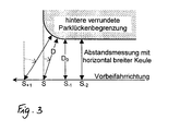
Anhand von Figur 3 ist die Arbeitsweise der erfindungsgemäßen Vorrichtung weiter
erläutert.By comparing the distance-dependent backscatter amplitudes of both
The mode of operation of the device according to the invention is further explained with reference to FIG. 3.
Es seien kastenförmige hintere Parklückenbegrenzungen angenommen. Bei der
Vorbeifahrt an ihnen liefert der Sensor 1 nahezu dieselbe Objektinformation wie der
Sensor 2, da der in Reflexionsrichtung bestrahlte Flächenbereich der Seitenfläche
der Parklückenbegrenzungen sich für die beiden Sensoren so gut wie nicht unterscheidet.
Nach Passieren der Vorderseite befinden sich für beide Sensoren dann
praktisch keine Flächenelemente mehr in Reflexionsrichtung, die Intensität der Abstandssignale
fällt bei beiden Sensoren abrupt ab.Box-shaped rear parking space limitations are assumed. In the
Passing them,
Ist die Vorderseite der hinteren Parklückenbegrenzung aber abgerundet, fällt nach
dem Passieren ihrer Stirnfläche die Rückstreuintensität des Sensors 1 wegen der in
horizontaler Richtung stärkeren Bündelung wesentlich schneller ab als die des Sensors
2, der mit seiner horizontal breiten Keule die Verrundung in Rückschau noch
länger detektiert.However, if the front of the rear parking space boundary is rounded, it falls
the backscattering intensity of the
Bei S beginnt die Parklücke. Die dort gemessene Entfernung D ist wegen der Rückschau
schon größer als D0. Der Sensor 1 mit horizontal schmaler Keule findet je
nach der geometrischen Formgestalt dort schon keine Flächenanteile in Reflexionsstellung
mehr vor, zugleich steigt aber das Bodensignal (Clutter) aus Entfernungen
> D0 deutlich an. Die wegabhängige Entwicklung dieses Bodensignals bietet damit
eine Korrekturmöglichkeit zu der Bestimmung des Endes der Parklückenbegrenzung.The parking space begins at S. The distance D measured there is because of the review
already larger than D0. The
Entsprechendes gilt für die Erfassung der Rückseite der vorderen Parklückenbegrenzung.The same applies to the detection of the rear of the front parking space limitation.
Eine Vermeidung gegenseitiger Beeinflussung beider Sensoren kann durch Wahl leicht unterschiedlicher Betriebsfrequenzen, alternierender Betriebsart oder geeigneter Modulationsverfahren gewährleistet werden.The choice of avoiding mutual interference between the two sensors can be avoided slightly different operating frequencies, alternating operating mode or more suitable Modulation procedures are guaranteed.
Durch eine Kombination zweier billiger Sensoren 1 und 2 wird ein Funktionsumfang
erzielt, der alternativ nur mit bedeutend aufwendigerer und teurerer Sensorik (Multibeam-
oder Scanner-Systeme) zu erzielen ist. Die Messgenauigkeit für die Parklückenlänge
wird wesentlich weniger durch unterschiedliche geometrische Parklücken-Begrenzungsformen
beeinflusst. By combining two
Damit steigt der Nutzungsgrad von auf dieser Vermessung aufbauenden Fahrer-Assistenzsysteme, mit deren Hilfe beispielsweise der Parkiervorgang unterstützt bzw. selbsttätig durchgeführt wird.This increases the degree of utilization of driver assistance systems based on this measurement, with the help, for example, of the parking process or is carried out automatically.
Claims (4)
Applications Claiming Priority (2)
| Application Number | Priority Date | Filing Date | Title |
|---|---|---|---|
| DE10146712A DE10146712A1 (en) | 2001-09-21 | 2001-09-21 | Parking aid device for motor vehicles |
| DE10146712 | 2001-09-21 |
Publications (3)
| Publication Number | Publication Date |
|---|---|
| EP1296412A2 true EP1296412A2 (en) | 2003-03-26 |
| EP1296412A3 EP1296412A3 (en) | 2004-01-07 |
| EP1296412B1 EP1296412B1 (en) | 2006-09-27 |
Family
ID=7699889
Family Applications (1)
| Application Number | Title | Priority Date | Filing Date |
|---|---|---|---|
| EP02014501A Expired - Lifetime EP1296412B1 (en) | 2001-09-21 | 2002-06-29 | Parking aid device for motor vehicles |
Country Status (4)
| Country | Link |
|---|---|
| US (1) | US6819284B2 (en) |
| EP (1) | EP1296412B1 (en) |
| DE (2) | DE10146712A1 (en) |
| ES (1) | ES2273949T3 (en) |
Cited By (1)
| Publication number | Priority date | Publication date | Assignee | Title |
|---|---|---|---|---|
| WO2009089938A1 (en) * | 2008-01-16 | 2009-07-23 | Robert Bosch Gmbh | Device and method for measuring a parking gap |
Families Citing this family (30)
| Publication number | Priority date | Publication date | Assignee | Title |
|---|---|---|---|---|
| DE10220837A1 (en) * | 2002-05-08 | 2003-11-27 | Daimler Chrysler Ag | Device for parking space search by means of radar |
| US7290161B2 (en) | 2003-03-24 | 2007-10-30 | Intel Corporation | Reducing CPU and bus power when running in power-save modes |
| US7888485B2 (en) * | 2003-03-26 | 2011-02-15 | Georgetown University | Anti-pleiotrophin antibodies and methods of use thereof |
| DE10325709A1 (en) * | 2003-06-06 | 2004-12-23 | Valeo Schalter Und Sensoren Gmbh | Device and method for recognizing the contour of an obstacle |
| DE10326385A1 (en) * | 2003-06-12 | 2004-12-30 | Valeo Schalter Und Sensoren Gmbh | Parking aid device and method for determining the length of a parking space |
| DE10339645A1 (en) | 2003-08-28 | 2005-04-14 | Robert Bosch Gmbh | Method and device for determining the size and position of a parking space |
| DE10343331A1 (en) | 2003-09-12 | 2005-04-07 | Valeo Schalter Und Sensoren Gmbh | Method and computer program for detecting the contour of an obstacle in the surroundings of a vehicle |
| DE102004029038A1 (en) * | 2004-06-09 | 2006-07-06 | Valeo Schalter Und Sensoren Gmbh | Parking assistance system |
| JP4461920B2 (en) * | 2004-06-23 | 2010-05-12 | 株式会社デンソー | Parking assistance device |
| DE102004033078A1 (en) * | 2004-07-08 | 2006-01-26 | Robert Bosch Gmbh | Method and device for measuring a parking space for a parking assistance system of a motor vehicle |
| US20060287829A1 (en) * | 2005-06-15 | 2006-12-21 | Dimitri Pashko-Paschenko | Object proximity warning system |
| DE102005028361A1 (en) * | 2005-06-18 | 2006-12-28 | Conti Temic Microelectronic Gmbh | Device for recognition of obstacles, e.g. roadway curbs, has a narrow scanning beam for vehicle side e.g. with an scanning angle smaller than 5degrees x 5degrees and is directed vertically on the base lateral to the vehicle |
| JP2007030700A (en) * | 2005-07-27 | 2007-02-08 | Aisin Seiki Co Ltd | Parking support device |
| DE102006007150A1 (en) * | 2005-08-05 | 2007-02-08 | Volkswagen Ag | Parking spot measuring device for motor vehicle, has sensor system comprising two measuring levels, where measuring levels comprise angle that deviates from horizontal position of road surface level |
| DE102006007149B4 (en) * | 2005-08-05 | 2021-06-02 | Volkswagen Ag | Device and method for checking the parking space measurement of parking aid devices |
| DE102005044050A1 (en) * | 2005-09-15 | 2007-03-22 | Hella Kgaa Hueck & Co. | Method for parking space determination for motor vehicles |
| DE102006003489A1 (en) | 2006-01-25 | 2007-07-26 | Robert Bosch Gmbh | Motor vehicle`s e.g. passenger car, parking operation assisting device, has sensor with receiver receiving signal, which is transmitted by another sensor and reflected by object in parking space |
| DE102006004865A1 (en) * | 2006-02-02 | 2007-08-16 | Siemens Ag | Parking assistance system for vehicle, has sensor devices arranged at longitudinal side of vehicle and designed for detecting parking space for vehicle, where devices are arranged, such that its detection areas overlap modularly |
| DE102006037591A1 (en) * | 2006-08-11 | 2008-02-14 | Robert Bosch Gmbh | Device for detecting a moving object |
| US7653487B2 (en) * | 2006-10-06 | 2010-01-26 | Toyota Motor Engineering & Manufacturing North America, Inc. | Object detection apparatus and method |
| DE102006052083B4 (en) * | 2006-11-04 | 2009-06-10 | Iav Gmbh Ingenieurgesellschaft Auto Und Verkehr | Method and device for environmental monitoring of a vehicle |
| DE102006052085B4 (en) * | 2006-11-04 | 2010-11-11 | Iav Gmbh Ingenieurgesellschaft Auto Und Verkehr | Method and device environment monitoring |
| ATE535897T1 (en) * | 2007-12-18 | 2011-12-15 | Honda Motor Co Ltd | DEVICE FOR ASSESSING PARKING AVAILABILITY FOR VEHICLES |
| DE102008007667A1 (en) * | 2007-12-21 | 2009-06-25 | Robert Bosch Gmbh | Method for operating a parking aid system |
| US8229664B2 (en) * | 2008-04-28 | 2012-07-24 | Herbert William J | Curb detection device for motor vehicles |
| DE102009024016A1 (en) | 2009-06-05 | 2010-12-09 | Bayerische Motoren Werke Aktiengesellschaft | Device for assisting driver of motor vehicle during process of leaving parking space for preventing collision with forward object, has evaluation module determining signals of sensors and position of limitation points of objects |
| DE102012106691A1 (en) * | 2012-07-24 | 2014-01-30 | Valeo Schalter Und Sensoren Gmbh | Alternative installation of a hidden ultrasonic sensor in the motor vehicle |
| DE102016221693B4 (en) * | 2016-11-04 | 2022-09-22 | Audi Ag | Motor vehicle with multiple radar sensors |
| JP2020034403A (en) * | 2018-08-29 | 2020-03-05 | 京セラ株式会社 | Electronic apparatus, method for controlling electronic apparatus, and control program for electronic apparatus |
| KR20220038554A (en) * | 2020-09-18 | 2022-03-29 | 현대모비스 주식회사 | Method And Apparatus for Controlling Parking of Vehicle |
Citations (4)
| Publication number | Priority date | Publication date | Assignee | Title |
|---|---|---|---|---|
| EP0305907A1 (en) * | 1987-08-29 | 1989-03-08 | Bayerische Motoren Werke Aktiengesellschaft, Patentabteilung AJ-3 | Parking aid device |
| EP1068992A2 (en) * | 1999-07-14 | 2001-01-17 | DaimlerChrysler AG | Device for assisting reversing |
| US6265968B1 (en) * | 1998-02-14 | 2001-07-24 | Daimlerchrysler Ag | Vehicle with object detection device |
| DE20105340U1 (en) * | 2001-03-26 | 2001-07-26 | Daimler Chrysler Ag | Dimensional environment detection |
Family Cites Families (3)
| Publication number | Priority date | Publication date | Assignee | Title |
|---|---|---|---|---|
| NL153513B (en) | 1969-03-05 | 1977-06-15 | Rhone Poulenc Sa | PROCESS FOR PREPARING AROMATIC ALDEHYDES AND THE CORRESPONDING ALCOHOLS. |
| US3898653A (en) * | 1972-02-22 | 1975-08-05 | Mitsubishi Electric Corp | Automotive radar sensor |
| JP3114849B2 (en) * | 1995-12-25 | 2000-12-04 | 本田技研工業株式会社 | Detection range adjustment mechanism of vehicle obstacle detection device |
-
2001
- 2001-09-21 DE DE10146712A patent/DE10146712A1/en not_active Withdrawn
-
2002
- 2002-06-29 EP EP02014501A patent/EP1296412B1/en not_active Expired - Lifetime
- 2002-06-29 ES ES02014501T patent/ES2273949T3/en not_active Expired - Lifetime
- 2002-06-29 DE DE50208244T patent/DE50208244D1/en not_active Expired - Lifetime
- 2002-08-28 US US10/229,179 patent/US6819284B2/en not_active Expired - Fee Related
Patent Citations (4)
| Publication number | Priority date | Publication date | Assignee | Title |
|---|---|---|---|---|
| EP0305907A1 (en) * | 1987-08-29 | 1989-03-08 | Bayerische Motoren Werke Aktiengesellschaft, Patentabteilung AJ-3 | Parking aid device |
| US6265968B1 (en) * | 1998-02-14 | 2001-07-24 | Daimlerchrysler Ag | Vehicle with object detection device |
| EP1068992A2 (en) * | 1999-07-14 | 2001-01-17 | DaimlerChrysler AG | Device for assisting reversing |
| DE20105340U1 (en) * | 2001-03-26 | 2001-07-26 | Daimler Chrysler Ag | Dimensional environment detection |
Cited By (2)
| Publication number | Priority date | Publication date | Assignee | Title |
|---|---|---|---|---|
| WO2009089938A1 (en) * | 2008-01-16 | 2009-07-23 | Robert Bosch Gmbh | Device and method for measuring a parking gap |
| US8422737B2 (en) | 2008-01-16 | 2013-04-16 | Robert Bosch Gmbh | Device and method for measuring a parking space |
Also Published As
| Publication number | Publication date |
|---|---|
| DE50208244D1 (en) | 2006-11-09 |
| DE10146712A1 (en) | 2003-04-10 |
| EP1296412B1 (en) | 2006-09-27 |
| ES2273949T3 (en) | 2007-05-16 |
| EP1296412A3 (en) | 2004-01-07 |
| US20030058132A1 (en) | 2003-03-27 |
| US6819284B2 (en) | 2004-11-16 |
Similar Documents
| Publication | Publication Date | Title |
|---|---|---|
| EP1296412B1 (en) | Parking aid device for motor vehicles | |
| DE112009000681B4 (en) | Parking space monitoring device | |
| EP1764630B1 (en) | Method of determining the size of a parking place | |
| EP1478547B1 (en) | Method for parking a vehicle | |
| EP1478942B1 (en) | Radar sensor for motor vehicles with antenna sidelobe pointing at the road surface | |
| DE4435156C2 (en) | ultrasonic sensor | |
| WO1992001954A1 (en) | Collision-warning system | |
| EP1664838B1 (en) | Method and computer program for the detection of the contour of an obstacle in the surroundings of a vehicle | |
| EP1979763B1 (en) | Device and method for assisting a parking process of a vehicle | |
| DE102012025064A1 (en) | A method for maintaining a warning signal in a motor vehicle due to the presence of a target object in a warning area, in particular a blind spot area, corresponding driver assistance system and motor vehicle | |
| EP1624278B1 (en) | Air spring with a measurement device for determining the distance of motor vehicle parts | |
| DE19842250A1 (en) | Method for determining the distance between an object and a locally changing device, in particular a motor vehicle | |
| DE102012212150A1 (en) | Laser radar device for use in driver assistance system to detect objects in surroundings of motor vehicle, has receiver, where spatial relationship of radiation or reception range prevents that receiver receives echo from object | |
| EP2804013A1 (en) | Device for measuring the position of a vehicle or a surface thereof | |
| DE102006049879A1 (en) | Radar system for use in adaptive cruise control-system of motor vehicle i.e. passenger car, has radar sensors integrated in front in vehicle and monitoring front end of vehicle, where two of radar sensors are long range radar sensors | |
| DE102015200939A1 (en) | Method and system for detecting objects in the vicinity of a vehicle | |
| EP1934630B1 (en) | Device and method for assisting a parking process of a vehicle | |
| EP1506432A1 (en) | Sensor for transmitting and receiving electromagnetic signals | |
| DE19757847A1 (en) | Scanner for optical object detection arrangement, especially in immediate vicinity of motor vehicles | |
| DE102018200688B4 (en) | Method and device for operating an acoustic sensor | |
| DE10349755B3 (en) | Sensor on a motor vehicle for detecting obstructions and distances from other motor vehicles has a detection range aligned crosswise to the vehicle's longitudinal axis | |
| DE102006043953A1 (en) | Method for operating a motor vehicle radar system and motor vehicle radar system | |
| DE102017208268B3 (en) | sensor arrangement | |
| DE3832720A1 (en) | DISTANCE MEASURING DEVICE FOR CONTACTLESS DISTANCE AND ANGLE DETECTION | |
| EP1762861B1 (en) | Method and device for determining the geometry and position of a parking place |
Legal Events
| Date | Code | Title | Description |
|---|---|---|---|
| PUAI | Public reference made under article 153(3) epc to a published international application that has entered the european phase |
Free format text: ORIGINAL CODE: 0009012 |
|
| AK | Designated contracting states |
Kind code of ref document: A2 Designated state(s): AT BE CH CY DE DK ES FI FR GB GR IE IT LI LU MC NL PT SE TR |
|
| AX | Request for extension of the european patent |
Extension state: AL LT LV MK RO SI |
|
| PUAL | Search report despatched |
Free format text: ORIGINAL CODE: 0009013 |
|
| AK | Designated contracting states |
Kind code of ref document: A3 Designated state(s): AT BE CH CY DE DK ES FI FR GB GR IE IT LI LU MC NL PT SE TR |
|
| AX | Request for extension of the european patent |
Extension state: AL LT LV MK RO SI |
|
| RIC1 | Information provided on ipc code assigned before grant |
Ipc: 7H 01Q 25/00 B Ipc: 7G 01S 13/93 A |
|
| 17P | Request for examination filed |
Effective date: 20040117 |
|
| AKX | Designation fees paid |
Designated state(s): DE ES FR GB IT SE |
|
| 17Q | First examination report despatched |
Effective date: 20041221 |
|
| GRAP | Despatch of communication of intention to grant a patent |
Free format text: ORIGINAL CODE: EPIDOSNIGR1 |
|
| GRAS | Grant fee paid |
Free format text: ORIGINAL CODE: EPIDOSNIGR3 |
|
| GRAA | (expected) grant |
Free format text: ORIGINAL CODE: 0009210 |
|
| AK | Designated contracting states |
Kind code of ref document: B1 Designated state(s): DE ES FR GB IT SE |
|
| PG25 | Lapsed in a contracting state [announced via postgrant information from national office to epo] |
Ref country code: IT Free format text: LAPSE BECAUSE OF FAILURE TO SUBMIT A TRANSLATION OF THE DESCRIPTION OR TO PAY THE FEE WITHIN THE PRESCRIBED TIME-LIMIT;WARNING: LAPSES OF ITALIAN PATENTS WITH EFFECTIVE DATE BEFORE 2007 MAY HAVE OCCURRED AT ANY TIME BEFORE 2007. THE CORRECT EFFECTIVE DATE MAY BE DIFFERENT FROM THE ONE RECORDED. Effective date: 20060927 |
|
| REG | Reference to a national code |
Ref country code: GB Ref legal event code: FG4D Free format text: NOT ENGLISH |
|
| GBT | Gb: translation of ep patent filed (gb section 77(6)(a)/1977) |
Effective date: 20060927 |
|
| REF | Corresponds to: |
Ref document number: 50208244 Country of ref document: DE Date of ref document: 20061109 Kind code of ref document: P |
|
| REG | Reference to a national code |
Ref country code: SE Ref legal event code: TRGR |
|
| ET | Fr: translation filed | ||
| REG | Reference to a national code |
Ref country code: ES Ref legal event code: FG2A Ref document number: 2273949 Country of ref document: ES Kind code of ref document: T3 |
|
| PLBE | No opposition filed within time limit |
Free format text: ORIGINAL CODE: 0009261 |
|
| STAA | Information on the status of an ep patent application or granted ep patent |
Free format text: STATUS: NO OPPOSITION FILED WITHIN TIME LIMIT |
|
| 26N | No opposition filed |
Effective date: 20070628 |
|
| PGFP | Annual fee paid to national office [announced via postgrant information from national office to epo] |
Ref country code: IT Payment date: 20120626 Year of fee payment: 11 |
|
| PG25 | Lapsed in a contracting state [announced via postgrant information from national office to epo] |
Ref country code: IT Free format text: LAPSE BECAUSE OF NON-PAYMENT OF DUE FEES Effective date: 20130629 |
|
| PGFP | Annual fee paid to national office [announced via postgrant information from national office to epo] |
Ref country code: GB Payment date: 20140626 Year of fee payment: 13 |
|
| PGFP | Annual fee paid to national office [announced via postgrant information from national office to epo] |
Ref country code: ES Payment date: 20140509 Year of fee payment: 13 |
|
| PGFP | Annual fee paid to national office [announced via postgrant information from national office to epo] |
Ref country code: DE Payment date: 20140702 Year of fee payment: 13 |
|
| PGFP | Annual fee paid to national office [announced via postgrant information from national office to epo] |
Ref country code: FR Payment date: 20140630 Year of fee payment: 13 |
|
| PGFP | Annual fee paid to national office [announced via postgrant information from national office to epo] |
Ref country code: SE Payment date: 20150611 Year of fee payment: 14 |
|
| REG | Reference to a national code |
Ref country code: DE Ref legal event code: R119 Ref document number: 50208244 Country of ref document: DE |
|
| GBPC | Gb: european patent ceased through non-payment of renewal fee |
Effective date: 20150629 |
|
| REG | Reference to a national code |
Ref country code: FR Ref legal event code: ST Effective date: 20160229 |
|
| PG25 | Lapsed in a contracting state [announced via postgrant information from national office to epo] |
Ref country code: GB Free format text: LAPSE BECAUSE OF NON-PAYMENT OF DUE FEES Effective date: 20150629 Ref country code: DE Free format text: LAPSE BECAUSE OF NON-PAYMENT OF DUE FEES Effective date: 20160101 |
|
| PG25 | Lapsed in a contracting state [announced via postgrant information from national office to epo] |
Ref country code: FR Free format text: LAPSE BECAUSE OF NON-PAYMENT OF DUE FEES Effective date: 20150630 |
|
| REG | Reference to a national code |
Ref country code: SE Ref legal event code: EUG |
|
| PG25 | Lapsed in a contracting state [announced via postgrant information from national office to epo] |
Ref country code: SE Free format text: LAPSE BECAUSE OF NON-PAYMENT OF DUE FEES Effective date: 20160630 |
|
| REG | Reference to a national code |
Ref country code: ES Ref legal event code: FD2A Effective date: 20170303 |
|
| PG25 | Lapsed in a contracting state [announced via postgrant information from national office to epo] |
Ref country code: ES Free format text: LAPSE BECAUSE OF NON-PAYMENT OF DUE FEES Effective date: 20150630 |