EP1289097A2 - Electric machine with toroidal coils - Google Patents
Electric machine with toroidal coils Download PDFInfo
- Publication number
- EP1289097A2 EP1289097A2 EP02255975A EP02255975A EP1289097A2 EP 1289097 A2 EP1289097 A2 EP 1289097A2 EP 02255975 A EP02255975 A EP 02255975A EP 02255975 A EP02255975 A EP 02255975A EP 1289097 A2 EP1289097 A2 EP 1289097A2
- Authority
- EP
- European Patent Office
- Prior art keywords
- iron core
- magnet
- pole
- electric rotating
- magnetic
- Prior art date
- Legal status (The legal status is an assumption and is not a legal conclusion. Google has not performed a legal analysis and makes no representation as to the accuracy of the status listed.)
- Withdrawn
Links
Images


Classifications
-
- H—ELECTRICITY
- H02—GENERATION; CONVERSION OR DISTRIBUTION OF ELECTRIC POWER
- H02K—DYNAMO-ELECTRIC MACHINES
- H02K3/00—Details of windings
- H02K3/46—Fastening of windings on the stator or rotor structure
-
- H—ELECTRICITY
- H02—GENERATION; CONVERSION OR DISTRIBUTION OF ELECTRIC POWER
- H02K—DYNAMO-ELECTRIC MACHINES
- H02K1/00—Details of the magnetic circuit
- H02K1/06—Details of the magnetic circuit characterised by the shape, form or construction
- H02K1/22—Rotating parts of the magnetic circuit
- H02K1/27—Rotor cores with permanent magnets
- H02K1/2706—Inner rotors
- H02K1/272—Inner rotors the magnetisation axis of the magnets being perpendicular to the rotor axis
- H02K1/274—Inner rotors the magnetisation axis of the magnets being perpendicular to the rotor axis the rotor consisting of two or more circumferentially positioned magnets
- H02K1/2753—Inner rotors the magnetisation axis of the magnets being perpendicular to the rotor axis the rotor consisting of two or more circumferentially positioned magnets the rotor consisting of magnets or groups of magnets arranged with alternating polarity
- H02K1/276—Magnets embedded in the magnetic core, e.g. interior permanent magnets [IPM]
- H02K1/2766—Magnets embedded in the magnetic core, e.g. interior permanent magnets [IPM] having a flux concentration effect
-
- H—ELECTRICITY
- H02—GENERATION; CONVERSION OR DISTRIBUTION OF ELECTRIC POWER
- H02K—DYNAMO-ELECTRIC MACHINES
- H02K1/00—Details of the magnetic circuit
- H02K1/06—Details of the magnetic circuit characterised by the shape, form or construction
- H02K1/12—Stationary parts of the magnetic circuit
- H02K1/14—Stator cores with salient poles
- H02K1/145—Stator cores with salient poles having an annular coil, e.g. of the claw-pole type
-
- H—ELECTRICITY
- H02—GENERATION; CONVERSION OR DISTRIBUTION OF ELECTRIC POWER
- H02K—DYNAMO-ELECTRIC MACHINES
- H02K21/00—Synchronous motors having permanent magnets; Synchronous generators having permanent magnets
- H02K21/12—Synchronous motors having permanent magnets; Synchronous generators having permanent magnets with stationary armatures and rotating magnets
- H02K21/22—Synchronous motors having permanent magnets; Synchronous generators having permanent magnets with stationary armatures and rotating magnets with magnets rotating around the armatures, e.g. flywheel magnetos
- H02K21/227—Synchronous motors having permanent magnets; Synchronous generators having permanent magnets with stationary armatures and rotating magnets with magnets rotating around the armatures, e.g. flywheel magnetos having an annular armature coil
-
- H—ELECTRICITY
- H02—GENERATION; CONVERSION OR DISTRIBUTION OF ELECTRIC POWER
- H02K—DYNAMO-ELECTRIC MACHINES
- H02K3/00—Details of windings
- H02K3/04—Windings characterised by the conductor shape, form or construction, e.g. with bar conductors
- H02K3/28—Layout of windings or of connections between windings
Definitions
- the present invention relates to an electric rotating machine and an electromagnetic machine and apparatus and further relates to an electric motor, a generator and an electromagnetic machine and apparatus in which magnets and electromagnets are used singly or together with.
- the present invention relates to a technical field in which an efficiency during a low speed and a low output of the electric rotating machine can be made rapid progress and a heat withstanding performance for forming a compact and a light weight structure can be increased to twice.
- a member in a stator of a conventional generator and a conventional electric motor and a member in a conventional wound rotor are manufactured by assembling a winding in slots, which are provided in laminated electromagnetic steel plates as winging insertions.
- the winding number is altered, except for a case where an outer form of the iron core is formed specially large, in ordinary an eight-pole structure is the limit.
- an output adjustment, a start torque adjustment, and an efficiency-up adjustment are carried out mainly by the adjustment in the winding or the adjustment of the strength of the magnet.
- pole number alternation of a magnet iron core portion is constituted structurally and fixedly to the outer periphery of the rotor but only the polarity alternation of the magnet is carried out.
- the iron core is generally constituted according to the integral lamination but there is no divisional system.
- the lamination iron core of the stator and the rotor is constituted in a straight form in a circumferential direction or is skewed with a zigzag form. In this case, there is no structure according to the divisional system of the iron core.
- the integral structure is generally but there are no divisional system and a combination of a magnetic body and a non-magnetic body in which a magnetic force is adjusted.
- a conventional electric rotating machine having an iron core winding structure used in a ultra-super high temperature environment has the limit of 250° C in a temperature in which a periphery temperature and a temperature rise value of the coil.
- the efficiency during a low speed and during a low output is very low, this is generally from 20 ° C to 30 ° C even in a conventional magnet type electric rotating machine.
- the present invention is to provide the technical problems which are (1) the simplification of the winding structure according to the iron core structure, material, and construction, and (2) the realization of the innovative efficiency-up during the low output according to the rapid progress improvement of the start improvement.
- the present invention is to provide the technical problems which are, (3) the structure realization of the iron core and the magnet enable to correspond the various kinds and the small productions, and (4) the realization of an electric rotating machine having a high heat withstanding and an electric rotating machine having a compact type and a light weight structure.
- a single-phase electric rotating machine and an electromagnetic machine and apparatus having a single-phase iron core being applied to a bobbin type winding, among plural iron cores, a relative angle of a part or all of magnetic poles is altered from zero degree to several degrees, thereby a voltage adjustment and an output adjustment are carried out by keeping pace of a series state and a parallel state of the winding and a change-over a tap.
- an electric rotating machine and an electromagnetic machine and apparatus having a bobbin type winding electromagnet structure, from two-pole to N pole is altered freely by an installation manner of a magnetic pole piece.
- an electromagnet structure having an iron core used in a bobbin type winding, to reduce an eddy current of an iron core in a pole piece and a york portion, said iron core is constituted by one selected from a surrounding metal fittings and a lamination iron core, an iron core constituted by a thin wire member, a vessel and a ferro-powdered iron core, and a thick material having plural thin grooves.
- an electric rotating machine and an electromagnetic machine and apparatus having an iron core which is constituted integrally in an inner peripheral direction of an iron core used in a bobbin winding, to lessen a magnetism of resistance gone across between pole pieces of different poles, in a part of a york portion, said iron core is constituted by one selected from a surrounding metal fittings and a lamination iron core, an iron core constituted by a thin wire member, a vessel and a ferro-powdered iron core, and a thick material having plural thin grooves.
- an electric rotating machine and an electromagnetic machine and apparatus having a bobbin winding iron core, to make smoothly a flow of magnetic field of mutual poles said iron core is arranged in a radial direction and is combined with a wedge shape iron core.
- an electric rotating machine and an electromagnetic machine and apparatus comprising a magnet type stator having a module and divided iron core or a magnet type rotor having a module and divided iron core, from two-pole to N pole is altered freely according to a magnet insertion manner, and a characteristic is altered freely according to a construction alternation of a strength and a cancellation using a magnetic body including a magnet, a magnetic shunt steel and a non-magnetic body.
- an electric rotating machine and an electromagnetic machine and apparatus comprising a magnet type stator having a module and divided iron core or a magnet type rotor having a module and divided iron core, a start adjustment or a characteristic adjustment is carried out by one selected from a short-circuit ring and a bridge using a magnetic body including a magnetic shunt steel and a non-magnetic body.
- an electric rotating machine and an electromagnetic machine and apparatus having a module and divided iron core, by replacing a cut-off portion with a non-magnetic body in a part of said divided iron core core, a cut-off shaped skew groove of said divided iron core is carried out to function effectively a skew effect.
- an electric rotating machine and an electromagnetic machine and apparatus having a magnet insertion space of an iron core in which a skew is formed by mounting a magnet, using said magnet insertion space to form the skew a magnet and an opened space are combined with a wedge shape magnetic body.
- an electric rotating machine and an electromagnetic machine and apparatus comprising a zigzag shape iron core which has formed a skew effect using a magnetic pole iron core, to not generate a magnetic short circuit between adjacent mutual iron cores, using only said delicate zigzag iron core a skewing is omitted.
- an electric rotating machine and an electromagnetic machine and apparatus having a magnet type rotor or a magnet type stator, an iron core for constituting a skew unit and a single or plural module thin magnets are combined.
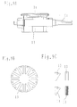
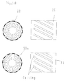
- Fig. 1A is an outer rotation type generator and a cross-sectional structure of the generator according to the present invention having a stator 3 which is constituted by a bobbin type electromagnet and a rotor 2 constituted by a magnet 14.
- the voltage When the rotor 2 is driven outside by a power drive source, to coils 36, 37 and 38 etc. wounded in the stator 3, the voltage generates in response to the rotation number, and to an electric power taken-out cord 7 when the loads such as the resistance are connected the current flows and the electric power is supplied.
- the generation voltage is proportional to the magnetic flux of an air gap formed between the stator 3 and the rotor 2 and also proportional to the rotation number.
- the present invention shows an example of the construction in which the bobbin type structure stator 3 is used to construct by four iron cores 22, the coils 36, 37, 37 and 38.
- the material of the iron core 22 is made by the ferro-group sintering material in which the eddy current hardly flows against the alternating current magnetic field, the combination of the laminating component of plural electromagnetic steel sheets in which the productivity is taken into consideration, or the combination of the laminating component of the sintering material and the electromagnetic steel sheets, etc..
- a coil having the high occupying property is wounded fully with the wind thread on a bobbin, which is formed with a reel shape and has the electrically high insulation property.
- the wire winding-into work to this reel is carried out by mounting many reels in a shaft of the electric motor and then the wire assembling work is finished once by the winding.
- This manner has the particular differences in comparison with the conventional assembling work for assembling to the lamination iron core and introduces cheap in a production cost and has a superior reliability in an insulation performance.
- FIG. 2A shows an electromagnet used in a stator and a wound rotor of a single-phase twelve-pole electric rotating machine.
- FIG. 2A shows a cross-sectional view of a single-phase stator, which is constituted by three electromagnets of from A1-phase to A3-phase, used in an inner rotation type electric rotating machine.
- Reference numerals 22a, 22b, 22c and 22d denote the electromagnetic iron cores which are formed by the sintering material and the lamination iron core and enclose effectively a bobbin coil 31a etc.
- Reference numeral 18 denotes a side plate which is formed by a non-magnetic body such as a stainless steel and constitutes strongly the respective electromagnets and at the same time combines mechanically the each phases of the electromagnet.
- Fig. 2B is shows an example in which three electromagnets are constituted electrically at the same phase
- Fig. 2C shows an example in which the each phase of the electromagnets is sifted electrically with the electric angle of a
- Fig. 2D shows an example in which A1-phase and A2-phase are the same phase and A3-phase is shifted to the other phases with the electric angle of b.
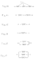
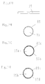
- FIG. 3A-3F shows six examples of the connection of a coil 31a between the respective phases of the single-phase stator.
- Fig. 3A is an example in which the coils of each phases are connected in series state
- Fig. 3B shows an example in which the coil of the one phase among the three phases has in idle
- Fig. 3C is an example in which two coils have in idle.
- Fig. 3D to Fig. 3F show examples the coils of the each phases are connected in parallel state
- Fig. 3D shows an example in which two coils among the three phases have in idle and substantially has the same result shown in Fig. 3C
- Fig. 3E shows an example in which one coil among the three phases has in idle
- Fig. 3F shows an example in which coils of all phases among the three phases are used in parallel state.
- FIG. 4A-4E shows a vector view of a generation voltage in a case in which an arrangement of the electromagnet of Fig. 2 and the various manners of the connections of Fig. 3 are used as the generator.
- Fig. 4A shows the generation voltage of a case where under the state of the arrangement of the three-phase and same phase of Fig. 2B the three-phase coil of Fig. 3A is connected in series state.
- Fig. 4B and Fig. 4C show the examples of the generation voltages of the cases where under the state of the arrangement of the three-phase and same phase the one-phase coil or the two-phase coil has in idle.
- FIG. 4D and Fig. 4E shows the example of the generation voltages of the cases where under the state of the shift of each phase of Fig. 2C.
- Fig. 4D shows the voltage of the case where the three-phase coil is connected in series state
- Fig. 4E shows the voltage of the case where the one-phase coil among the three-phase coil has in idle.
- Fig. 4F shows an example of the generation voltage the three-phase coil in the electromagnet of Fig. 2D is connected in series state.
- FIG. 5A and Fig. 5B shows an explanatory view showing the concrete examples in which the alternations of the bobbin type electromagnet for constituting the stator or the rotor are carried out easily.
- Fig. 5A shows a cross-sectional view of the bobbin type three-phase stator and this stator is constituted by the iron cores 22a, 22b, 22c which are formed by the lamination or the sintering and a pole piece 22d and they are sandwiched to side plates 18 and each of the phase is consisted independently. Since the iron cores 22a and 22d are formed that the polarity of the magnetic pole is altered freely, the polarity of the pole piece iron core 22c is altered at any installation place.
- Reference numerals 31, 32 and 33 denote a main coil of the each phase wounded on a bobbin insulating member 41 and a coil used for the magnetic engagement with the other phase.
- Fig. 5B shows a cross-sectional view for explaining the installation status of the different polarities of the pole piece iron core 22c and here the polarity of the upper portion and the polarity of the lower portion are different.
- Reference numeral 4a denotes a shaft.
- Fig. 5C and Fig. 5D shows the example in which a stator having a twelve-pole and a stator having a six-pole are constituted, respectively.
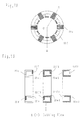
- FIG. 6A is a cross-sectional view of the stator and this stator is constituted by the iron cores 22a, 22b, 22c and 22d and a coil 31a, etc.
- Fig. 6B is a side view of the stator and windows C for drawing out to an outside the lead wires of the respective phase are provided.
- Fig. 6C is an explanatory view showing one example of components of the twelve-phase electric rotating machine for constituting the stator and to inner diameter projection portions of the iron cores 22a and 22d six pole pieces 22c are installed and then the magnetic poles are formed.
- the formed magnetic pole and a bobbin-wounded coil 31a is enclosed by the iron core 22b and according to the two side plates 18 the stator of the each phase is formed sandwiched.
- the pole piece iron core 22c is formed by the laminated iron cores shown in figure and this is enable to be formed by the sintering, the vessel type member in which the ferro-powder are enclosed, the thick ferro-piece member in which the thin groove is formed lengthily and laterally, and the iron core constituted by binding the thin steel wire and they are made by the materials in which the alternation loss is small to the alternating magnetic field.
- These iron cores can apply to the iron core 22c and also cab apply to other iron cores.
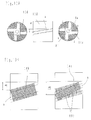
- FIG. 7A and Fig. 7B is an explanatory view of the stator construction in which among the iron cores used in the bobbin type winding a back portion and a side portion of the iron core and the pole piece portion are formed integrally and they are subdivided in the pole unit and formed by the lamination and sintering materials. Accordingly, the productivity performance is heightened remarkably in the various kinds and small amount production and in the mass production.
- Fig. 7A shows an example of the stator of the twelve-pole electric rotating machine which is constituted by the united cores and the iron core 22e is made by the steel plate which is formed by laminating with the necessary thick and making them as the unit and is arranged in the circumferential direction and further as the wedge member between the iron cores it is constituted by the iron core 22f which is formed by the lamination and sintering materials.
- Fig. 7B is an explanatory view of an example of A-O-B cross-section of Fig. 7A is formed by various kinds iron core materials and the materials of the iron cores 22e, 22e1, 22e2 and the wedge iron cores 22f, 22f1, 22f2 are replaced with and combined by the lamination and sintering materials.
- FIG. 8A, Fig. 8B and Fig. 8C shows a structure in which using the unit iron cores explained in Fig. 7 the alternation of the pole number in the same size machine and apparatus and the laminated thickness of the unit iron cores and the alternation of the thickness and the individual number of the case of the lamination are carried out and then the size of the stator is altered freely and without the relationship of the capacity it can correspond by one unit.
- Fig. 8A shows the stator which is constituted by the twelve-pole unit iron core 22e and the wedge iron core 22f explained in Fig. 7, and Fig. 8B shows an example a six-pole stator is formed by the unit iron core 22e and the connection iron core 22f.
- Fig. 8C shows an example in which a twelve-pole stator is formed by the wedge iron core 22f4 by making large the laminated thickness of the iron core 22e.
- a twelve-pole stator is formed by the wedge iron core 22f4 by making large the laminated thickness of the iron core 22e.
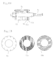
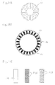
- FIG. 9A, Fig. 9B and Fig. 9C shows an example of the iron core in which the iron element 13 of the magnet type rotor is subdivided in the minimum and further is divided completely (for example, the twelve divisions) and according to the arrangement manner of the magnet, which is inserted into the slot formed between the iron cores, the alternation of the pole number is carried out easily and the cost of the special tool necessary for the production is made in the minimum.
- This iron core element may be manufactured as the block according to the forging work and the press working and it is formed by the thin steel plate in which the thickness is carried out by the lamination.
- Reference numeral 4c denotes the shaft.
- FIG. 10D shows a view of a formation example in which using the iron core element 13 explained in Fig. 9 a two-pole, a four-pole, a six-pole and a twelve-pole of a rotor magnet iron core.
- the magnets 14a and the magnetic body 60 such as an iron are combined and then the pole number alternation is carried out easily.
- Fig. 10A to form alternatively the magnetic poles to the slots 50 the polarity of the magnets 14a is changed alternatively and the magnets are inserted, accordingly the twelve-pole rotor is formed.
- Fig. 10B is an example in which a six-pole rotor is formed, to the pole center slot, a space in which the magnetic body 60 is not inserted is formed and to a space the magnetic body is inserted.
- the slot 50 is remained as the space is and there is inconvenient in the structure, the non-magnetic body or the magnetic body 60 may be inserted.
- Fig. 10C is an example in which a four-pole rotor is formed. To all of the slots 50, the magnets 14a are inserted and a strong magnet rotor is formed or to the magnetic pole center portion using the two slots 50 the magnetic body 60, the magnet 14a and a weak magnet etc. are combined and then the magnetic field and the magnetic flux distribution etc. are adjusted and the voltage waveform of the characteristics of the generator are altered.
- Fig. 10D shows an example of a two-pole rotor. The insertion of the magnet 14a and the practical use of the space of the magnetic body 60 and the slot is carried out by the above stated manner.
- FIG. 11A and Fig. 11B shows a view of a formation example in which using the iron core element 13 explained in Fig. 11A a two-pole, a four-pole, a six-pole and a twelve-pole of a rotor magnet iron core.
- the manner of the magnetic short circuit between the magnetic poles changes and then the magnetic field of the air gap can be changed largely.
- the magnetic shunt steel when the magnetic shunt steel is employed, during the low temperature such as the start time since it works as the magnetic body, then it exhibits the effect for weakening the magnetic field of the air gap. However, when the temperature is arisen under the operation state it can not work as the magnetic body and it returns to the state in which the magnetic field is not adjusted, accordingly it is valid to lower only the start torque.
- the non-magnetic body 70b When the minute adjustment in the magnetic filed is carried out, to between and the intermediate portion of the magnetic body 70 and the magnetic shunt steel 70a and the iron core 13 the non-magnetic body 70b may be inserted and then the adjustment is carried out.
- FIG. 12D shows an example in which the end portion members of the axial direction of the iron core 13 in Fig. 12B of the magnet rotor 2b of Fig. 12A are replace with the magnetic shunt steel 13b having the same shape of the iron cores 13a in which a cut-off portion is provided on the portion facing to the air gap shown in Fig. 12C and the iron core 13 and the non-magnetic body 13c.
- FIG. 13A and Fig. 13B shows an example in which using a space of the magnets 14b which is inserted the slots a between the skewed iron cores 13 of the four-pole rotor shown in Fig. 13A, and to obtain further the skew effect, the magnets are replaced with the magnets 14b shown in Fig. 13B.
- the magnets 14c thinner than the magnet 14b and the wedge shape magnetic body 60b are combined and not to generate the gap they are inserted into the slots a, accordingly against a skew width W1 in the prior art a larger width W2 is obtained.
- FIG. 14A, Fig. 14B and Fig. 14C shows an example of a magnet rotor and a stator in which within a thickness of the iron cores 13e and 13f used in the magnet rotor and the stator a single number shown in Fig. 14A or plural number of the magnets 14d and 14e etc. shown in Fig. 14B which are mounted on a protein structure direction in the lengthwise, the lateral and the depth is constituted to be inserted to the slots a.
- the delicate skew effect is carried out without the skewing and the strong and the distribution of the magnetic flux in the air gap are carried out and it can assemble simply with the low cost.
- the magnet is carried out the module performance in the minimum unit and only a single number it can use to much amounts, and the production cost of the magnet used in the single number is reduced about 1/6 degree.
- Reference numeral 81a denotes a non-magnetic body spacer.
- Fig. 14C is a cross-sectional view of the rotor.
- Figs. 15A-15B and Figs. 16A-16C show examples of a magnet rotor and a magnet stator in which using the module and divided iron cores 13 and 13f the pole number alternation and the capacity alternation are carried out easily.
- Figs. 15A and Fig. 15B will be explained.
- Fig. 15A shows an example of four-pole rotor and the rotor is constituted by the module iron core 13f, the magnet 14f and the non-magnetic body 81b etc. and the rotor of an inner rotation type electric rotating machine and the stator of an outer rotation type electric rotating machine are exemplified.
- Fig. 15B shows an example in which using the module iron core 13f and the magnet 14f, the rotor having the large capacity about two times of the outer diameter and the stator are formed.
- the magnetic body 60c and the magnetic shunt steel etc. According to the magnet, the magnetic body 60c and the magnetic shunt steel etc., the space in the slot which is formed between two magnets 14f is buried and the loss in the magnetic field is prevented.
- Figs. 16A-16C show the module iron core 13 used for the rotor and the stator of a twelve-pole electric rotating machine
- Fig. 16B shows an example of the magnet rotor and the magnet stator in which the twenty-four iron cores 13 are used.
- Reference numeral 14g denotes a magnet
- reference numeral 60e denotes a magnetic body, etc..
- Fig. 16C shows an example of the construction of the magnet 14g and it is constituted by a single magnet or plural magnets such as three numbers or four numbers. In the case of a large size machine, by dividing lengthily and laterally and then the work performance is increased.
- FIG. 17A to Fig. 17D shows an example in which, to improve the heat withstanding performance about two times in comparison with that of the prior art, an outer skin of the coil wire member 36 shown in Fig. 17A is covered by the heat withstanding member such as the alumina, the silica, and the silicone rubber, etc..
- Fig. 17B shows an example of a layer 85 in which the outer skin of the alumina wire member is treated by the eloxation processing.
- Fig. 17C shows an example in which to the wire 35a on which an eloxation film 85a is formed to increase further the insulating strength plural films 65b are formed using the same material and other materials.
- Fig. 17D shows an example in which to the outer skin of the wire member 35b after the silicone resin having the protein structure bridge etc. (under the nitrogen atmosphere and under the temperature of 1000 °C, the reduction rate is 5 %) have covered, the alumina and the silica are covered and the flexibility of the wire member is increased remarkably and at the same time the heat withstanding performance is obtained.
- Reference numeral 35 denotes a wire member and reference numeral 85c denotes the heat withstanding resin such as the silicone resin and reference numeral 85d denotes a heat withstanding electric insulating body which is made by the alumina and the silica.
- the wire member having the good flexibility has the effects in which the electric wiring work of the winding wire etc. is carried out easily and it can endure fully against the vibration during the use time and the impact.
- FIG. 18A and Fig. 18B shows an example in which the air gap g1 between the stator iron core 23 having the several time winding slots in comparison with that of the prior art in which the start torque (1 gm) and the cogging are formed in the minimum or is not haven and the rotor 2a is formed wider at the 2-2.5 times of the air gap g2 between the stator iron core 23a and the rotor 2b shown in Fig. 18B.
- the slot 51 of the stator is formed larger and the minimum start torque and the efficiency during the low speed output time is increased remarkably (more than 95 %) and then such an electric rotating machine is realized.
- Reference numeral 52 denotes a slot of the stator iron core in the conventional type
- reference numeral 2b denotes a shaft.
- Fig. 19A shows an example in which to shift in phase the respective poles in the arrangement of the slot of the stator one portion of a width Wa of teeth portions of the electromagnet iron core 23b is formed wider than a width Wb of the other teeth portions.
- Fig. 19B an example in which to shift in phase the respective poles in the arrangement of the slot of the stator one portion of a width Wc of teeth portions of the electromagnet iron core 23b is formed narrower than a width Wd of the other teeth portions.
- the low start torque is realized and the efficiency during the low speed and the low output is improved remarkably (more than 95 %) and then the electric rotating machine having the very small vibration noises is realized.
- Reference numeral 53 denotes slots to which the winding is inserted.
- Reference numerals 2c and 2d denote rotors, and reference numeral g1 denotes an air gap.
- Fig. 20A shows an example in which to shift in phase the respective poles in the arrangement of the slot of the stator one portion of a width We of the slit between adjacent magnet iron cores 13g is formed wider than a width Wf of the other slits.
- Fig. 20B shows an example in which to shift in phase the respective poles in the arrangement of the slot of the stator one portion of a width Wg of the slit between adjacent magnet iron cores 13h is formed narrow than a width Wh of the other slits.
- the low start torque is realized and the efficiency during the low speed and the low output is improved remarkably (more than 95 %) and then the electric rotating machine having the very small vibration noises is realized.
- Fig. 21A shows an example in which in which to shift in phase the respective magnetic poles of the arrangement of the bobbin winding type stator one portion of a width Wi between teeth portions of the electromagnet iron core 22e is formed wider than a width Wj between the other teeth portions.
- Fig. 21B shows an example in which in which to shift in phase the respective magnetic poles of the arrangement of the bobbin winding type stator one portion of a width Wk between teeth portions of the electromagnet iron core 22e is formed narrow than a width W1 between the other teeth portions.
- the low start torque is realized and the efficiency during the low speed and the low output is improved remarkably (more than 95 %) and then the electric rotating machine having the very small vibration noises is realized.
- the present invention can apply in addition to the above stated various kinds machine and apparatuses to the other kinds electric rotating machines and also to the other embodiments different machine and apparatuses, such as a pancake type electric machine, a linear motor, an electromagnet machine and apparatus.
Abstract
Description
- The present invention relates to an electric rotating machine and an electromagnetic machine and apparatus and further relates to an electric motor, a generator and an electromagnetic machine and apparatus in which magnets and electromagnets are used singly or together with.
- A magnetic pole structure, a winding structure and a combination theseof in which an output improvement, and an adjustment improvement, and an efficiency improvement can be improved, and further a productivity of a magnetic pole iron core and an electric work etc. can be made rapid progress.
- Further, the present invention relates to a technical field in which an efficiency during a low speed and a low output of the electric rotating machine can be made rapid progress and a heat withstanding performance for forming a compact and a light weight structure can be increased to twice.
- A member in a stator of a conventional generator and a conventional electric motor and a member in a conventional wound rotor are manufactured by assembling a winding in slots, which are provided in laminated electromagnetic steel plates as winging insertions.
- After the winding assembling work finish, winding end portions are connected and a formation and a fixing of an end coil are complicated and difficult work and become high from a cost aspect and a work process becomes long.
- Accordingly, it invites a lowering in reliability of an insulation destroy in a use such as the work and a twine and an interference in a narrow slot and between the windings, a lowering (ordinary 50%) in a slot occupation rate for making a work performance of an assembly wire performance, a cost-up according to an extension of an end coil, an increase of a resistance loss of an end coil portion accompanied by the above and an efficiency lowering and an output lowering etc. according to an increase etc. of leakage magnetic flux.
- Further, a machinery performance of a production is difficult and much equipment cost for carrying out the above is needed. Further, in a case of a low voltage and a middle and a large capacity electric rotating machine a diameter of a winding becomes large and then a work performance becomes further worse and a cost-up becomes widely. This is similar to a case of a single-phase wound motor.
- When the pole number is intended to alter in the conventional structure, the winding number is altered, except for a case where an outer form of the iron core is formed specially large, in ordinary an eight-pole structure is the limit. In a case of a magnet type electric motor or generator, an output adjustment, a start torque adjustment, and an efficiency-up adjustment are carried out mainly by the adjustment in the winding or the adjustment of the strength of the magnet.
- Further, the pole number alternation of a magnet iron core portion is constituted structurally and fixedly to the outer periphery of the rotor but only the polarity alternation of the magnet is carried out. The iron core is generally constituted according to the integral lamination but there is no divisional system.
- To reduce the start torque, the lamination iron core of the stator and the rotor is constituted in a straight form in a circumferential direction or is skewed with a zigzag form. In this case, there is no structure according to the divisional system of the iron core.
- Relating to the magnet, the integral structure is generally but there are no divisional system and a combination of a magnetic body and a non-magnetic body in which a magnetic force is adjusted.
- Further, a conventional electric rotating machine having an iron core winding structure used in a ultra-super high temperature environment has the limit of 250° C in a temperature in which a periphery temperature and a temperature rise value of the coil.
- In the conventional electric rotating machine, the efficiency during a low speed and during a low output is very low, this is generally from 20 ° C to 30 ° C even in a conventional magnet type electric rotating machine.
- Accordingly, according to a winding and an iron core structure and constructions of a stator and a rotor of an alternative current generator and an electric motor, etc. the present invention is to provide the technical problems which are (1) the simplification of the winding structure according to the iron core structure, material, and construction, and (2) the realization of the innovative efficiency-up during the low output according to the rapid progress improvement of the start improvement.
- Further, the present invention is to provide the technical problems which are, (3) the structure realization of the iron core and the magnet enable to correspond the various kinds and the small productions, and (4) the realization of an electric rotating machine having a high heat withstanding and an electric rotating machine having a compact type and a light weight structure.
- According to the present invention, a single-phase electric rotating machine and an electromagnetic machine and apparatus having a single-phase iron core being applied to a bobbin type winding, among plural iron cores, a relative angle of a part or all of magnetic poles is altered from zero degree to several degrees, thereby a voltage adjustment and an output adjustment are carried out by keeping pace of a series state and a parallel state of the winding and a change-over a tap.
- According to the present invention, an electric rotating machine and an electromagnetic machine and apparatus having a bobbin type winding electromagnet structure, from two-pole to N pole is altered freely by an installation manner of a magnetic pole piece.
- According to the present invention, an electromagnet structure having an iron core used in a bobbin type winding, to reduce an eddy current of an iron core in a pole piece and a york portion, said iron core is constituted by one selected from a surrounding metal fittings and a lamination iron core, an iron core constituted by a thin wire member, a vessel and a ferro-powdered iron core, and a thick material having plural thin grooves.
- According to the present invention, an electric rotating machine and an electromagnetic machine and apparatus having an iron core which is constituted integrally in an inner peripheral direction of an iron core used in a bobbin winding, to lessen a magnetism of resistance gone across between pole pieces of different poles, in a part of a york portion, said iron core is constituted by one selected from a surrounding metal fittings and a lamination iron core, an iron core constituted by a thin wire member, a vessel and a ferro-powdered iron core, and a thick material having plural thin grooves.
- According to the present invention, an electric rotating machine and an electromagnetic machine and apparatus having a bobbin winding iron core, to make smoothly a flow of magnetic field of mutual poles said iron core is arranged in a radial direction and is combined with a wedge shape iron core.
- According to the present invention, an electric rotating machine and an electromagnetic machine and apparatus comprising a magnet type stator having a module and divided iron core or a magnet type rotor having a module and divided iron core, from two-pole to N pole is altered freely according to a magnet insertion manner, and a characteristic is altered freely according to a construction alternation of a strength and a cancellation using a magnetic body including a magnet, a magnetic shunt steel and a non-magnetic body.
- According to the present invention, an electric rotating machine and an electromagnetic machine and apparatus comprising a magnet type stator having a module and divided iron core or a magnet type rotor having a module and divided iron core, a start adjustment or a characteristic adjustment is carried out by one selected from a short-circuit ring and a bridge using a magnetic body including a magnetic shunt steel and a non-magnetic body.
- According to the present invention, an electric rotating machine and an electromagnetic machine and apparatus having a module and divided iron core, by replacing a cut-off portion with a non-magnetic body in a part of said divided iron core core, a cut-off shaped skew groove of said divided iron core is carried out to function effectively a skew effect.
- According to the present invention, an electric rotating machine and an electromagnetic machine and apparatus having a magnet insertion space of an iron core in which a skew is formed by mounting a magnet, using said magnet insertion space to form the skew a magnet and an opened space are combined with a wedge shape magnetic body.
- According to the present invention, an electric rotating machine and an electromagnetic machine and apparatus comprising a zigzag shape iron core which has formed a skew effect using a magnetic pole iron core, to not generate a magnetic short circuit between adjacent mutual iron cores, using only said delicate zigzag iron core a skewing is omitted.
- According to the present invention, an electric rotating machine and an electromagnetic machine and apparatus having a magnet type rotor or a magnet type stator, an iron core for constituting a skew unit and a single or plural module thin magnets are combined.
-
- Fig. 1A is a structural view showing one embodiment of an outer rotation type generator having a stator which is constituted by a bobbin type electromagnet according to the present invention;
- Figs. 2A-2D are structural explanatory views of an electromagnet which is used a single phase twelve-pole electric rotating machine having a bobbin type winding iron core and a winding type rotor;
- Figs. 3A-3D are explanatory views of six examples of the coil connection between the respective phases of a single-phase stator having a bobbin type winding iron core;
- Figs . 4A-4F are explanatory views showing a vector view of the electric generation voltage in a case where it is used as a generator accompanying with an arrangement of an electromagnet having a bobbin type winding iron core and various kinds connection manners of the coil;
- Figs. 5A-5F are explanatory views showing a concrete embodiment in which an alternation in pole number of a bobbin type electromagnet for constituting a stator and a rotor is carried out easily;
- Figs. 6A-6C are explanatory views showing a concrete structural example of a twelve-pole stator which is constituted by a single phase bobbin iron core;
- Figs. 7A and 7B are explanatory views showing an example in which among iron cores used in a bobbin type winding wire a rear portion, a side portion and a pile piece portion of the iron core is formed integrally and it is suited to an alternation in pole number and capacity;
- Figs. 8A-8C are explanatory views showing a structure in which using an iron core element it is suited to correspond by one unit without an alternation in pole number and a largeness capacity in size;
- Figs. 9A-9C are views showing an example an iron core element is subdivided in minimum and a magnet type rotor is formed;
- Figs. 10A-10D are formation examples showing a two-pole, a four-pole, a six-pole and a twelve-pole rotor magnet iron core using an iron core element;
- Figs. 11A and 11B are explanatory views showing an adjustment example of characteristics using an adjustment plate of a magnetic body and a non-magnetic body using a space of one portion of an iron core;
- Figs. 12A-12D are explanatory views showing an example in which a part of a module iron core is cut off and it is replaced with a magnetic body and a non-magnetic body and using a skew ring in which an end portion of a skew groove is cut off, a skew effect is obtained;
- Figs. 13A and 13B are explanatory views showing an example in which in a magnet insertion slot in an iron core a thin magnet and a wedge shape magnetic body are assembled and mounted, a skew effect is obtained remarkably further;
- Figs. 14A-14C are explanatory views showing an example in which an iron core and a magnet in a thickness of the iron core are assembled and a skew formation is carried out easily;
- Figs. 15A and 15B are views showing an example in which using a module iron core and a magnet a magnet type rotor having a different capacity and a stator are constituted;
- Figs. 16A-16C are views showing another example in which using a module iron core and a magnet a magnet type rotor having a different capacity and a stator are constituted;
- Figs. 17A-17D are explanatory views showing a covered wire having a superior heat withstanding used in a winding wire;
- Figs. 18A and 18B are explanatory views of an example of a stator in which an area of a winding wire slot for realizing a low output and a high efficiency is increased with a several times in comparison with that of the prior art;
- Figs. 19A and 19B are explanatory views showing one example of a structure for realizing a low output and a high efficiency and for having a difference in phase between magnetic poles of a stator;
- Figs. 20A and 20B are explanatory views showing one example of a structure for realizing a low output and a high efficiency and for having a difference in phase between magnetic poles of a rotor; and
- Figs. 21A and 21B are explanatory views showing one example of a structure for realizing a low output and a high efficiency and for having a difference in phase between magnetic poles of a bobbin type winding stator.
-
- Hereinafter, the embodiments for carrying out the invention will be explained by exemplifying an outer rotation type generator referring to the drawings.
- Fig. 1A is an outer rotation type generator and a cross-sectional structure of the generator according to the present invention having a
stator 3 which is constituted by a bobbin type electromagnet and arotor 2 constituted by amagnet 14. - When the
rotor 2 is driven outside by a power drive source, to coils 36, 37 and 38 etc. wounded in thestator 3, the voltage generates in response to the rotation number, and to an electric power taken-outcord 7 when the loads such as the resistance are connected the current flows and the electric power is supplied. The generation voltage is proportional to the magnetic flux of an air gap formed between thestator 3 and therotor 2 and also proportional to the rotation number. - The present invention shows an example of the construction in which the bobbin
type structure stator 3 is used to construct by fouriron cores 22, thecoils - The material of the
iron core 22 is made by the ferro-group sintering material in which the eddy current hardly flows against the alternating current magnetic field, the combination of the laminating component of plural electromagnetic steel sheets in which the productivity is taken into consideration, or the combination of the laminating component of the sintering material and the electromagnetic steel sheets, etc.. - In the inner portion of the
iron core 22, a coil having the high occupying property is wounded fully with the wind thread on a bobbin, which is formed with a reel shape and has the electrically high insulation property. The wire winding-into work to this reel is carried out by mounting many reels in a shaft of the electric motor and then the wire assembling work is finished once by the winding. - This manner has the particular differences in comparison with the conventional assembling work for assembling to the lamination iron core and introduces cheap in a production cost and has a superior reliability in an insulation performance.
- Next, relating to the bobbin type electromagnet according to the present invention, the iron core structure, the stator structure and the winding structure of the electric motor and the generator will be explained referring to the drawings.
- Each of Figs. 2A and 2B shows an electromagnet used in a stator and a wound rotor of a single-phase twelve-pole electric rotating machine. Fig. 2A shows a cross-sectional view of a single-phase stator, which is constituted by three electromagnets of from A1-phase to A3-phase, used in an inner rotation type electric rotating machine.
-
Reference numerals bobbin coil 31a etc..Reference numeral 18 denotes a side plate which is formed by a non-magnetic body such as a stainless steel and constitutes strongly the respective electromagnets and at the same time combines mechanically the each phases of the electromagnet. - Fig. 2B is shows an example in which three electromagnets are constituted electrically at the same phase, Fig. 2C shows an example in which the each phase of the electromagnets is sifted electrically with the electric angle of a, and further Fig. 2D shows an example in which A1-phase and A2-phase are the same phase and A3-phase is shifted to the other phases with the electric angle of b.
- Each of Figs. 3A-3F shows six examples of the connection of a
coil 31a between the respective phases of the single-phase stator. Fig. 3A is an example in which the coils of each phases are connected in series state, Fig. 3B shows an example in which the coil of the one phase among the three phases has in idle, and Fig. 3C is an example in which two coils have in idle. - From Fig. 3D to Fig. 3F show examples the coils of the each phases are connected in parallel state, and Fig. 3D shows an example in which two coils among the three phases have in idle and substantially has the same result shown in Fig. 3C. Fig. 3E shows an example in which one coil among the three phases has in idle. Fig. 3F shows an example in which coils of all phases among the three phases are used in parallel state.
- Each of Figs. 4A-4E shows a vector view of a generation voltage in a case in which an arrangement of the electromagnet of Fig. 2 and the various manners of the connections of Fig. 3 are used as the generator. Fig. 4A shows the generation voltage of a case where under the state of the arrangement of the three-phase and same phase of Fig. 2B the three-phase coil of Fig. 3A is connected in series state.
- Fig. 4B and Fig. 4C show the examples of the generation voltages of the cases where under the state of the arrangement of the three-phase and same phase the one-phase coil or the two-phase coil has in idle.
- Each of Fig. 4D and Fig. 4E shows the example of the generation voltages of the cases where under the state of the shift of each phase of Fig. 2C. Fig. 4D shows the voltage of the case where the three-phase coil is connected in series state, and Fig. 4E shows the voltage of the case where the one-phase coil among the three-phase coil has in idle. Fig. 4F shows an example of the generation voltage the three-phase coil in the electromagnet of Fig. 2D is connected in series state.
- In the above, they are exemplified as the examples of the generation voltages, relating to the currents under the case where the loads are connected, it is possible to carry out the various controls according to the arrangements of the electromagnets and the status of the connections of the coil.
- Each of Fig. 5A and Fig. 5B shows an explanatory view showing the concrete examples in which the alternations of the bobbin type electromagnet for constituting the stator or the rotor are carried out easily. By the mounting manners of the pole
piece iron core 22c, when the electromagnet is N pole, it can alter simply from two-pole to N pole, or to adjust the number of the pole piece of the constituting the poles the electromagnet is constituted. - Fig. 5A shows a cross-sectional view of the bobbin type three-phase stator and this stator is constituted by the
iron cores pole piece 22d and they are sandwiched toside plates 18 and each of the phase is consisted independently. Since theiron cores piece iron core 22c is altered at any installation place. - Accordingly, the alternation of the pole number can be carried out easily.
Reference numerals bobbin insulating member 41 and a coil used for the magnetic engagement with the other phase. - Fig. 5B shows a cross-sectional view for explaining the installation status of the different polarities of the pole
piece iron core 22c and here the polarity of the upper portion and the polarity of the lower portion are different. Reference numeral 4a denotes a shaft. Each of Fig. 5C and Fig. 5D shows the example in which a stator having a twelve-pole and a stator having a six-pole are constituted, respectively. - Each of Fig. 6A, Fig. 6B and Fig. 6C shows a view for explaining a concrete structure example of a twelve-phase stator constituted according to a single-phase bobbin iron core. Fig. 6A is a cross-sectional view of the stator and this stator is constituted by the
iron cores coil 31a, etc.. Fig. 6B is a side view of the stator and windows C for drawing out to an outside the lead wires of the respective phase are provided. - Fig. 6C is an explanatory view showing one example of components of the twelve-phase electric rotating machine for constituting the stator and to inner diameter projection portions of the
iron cores pole pieces 22c are installed and then the magnetic poles are formed. The formed magnetic pole and a bobbin-woundedcoil 31a is enclosed by theiron core 22b and according to the twoside plates 18 the stator of the each phase is formed sandwiched. - The pole
piece iron core 22c is formed by the laminated iron cores shown in figure and this is enable to be formed by the sintering, the vessel type member in which the ferro-powder are enclosed, the thick ferro-piece member in which the thin groove is formed lengthily and laterally, and the iron core constituted by binding the thin steel wire and they are made by the materials in which the alternation loss is small to the alternating magnetic field. These iron cores can apply to theiron core 22c and also cab apply to other iron cores. - Each of Fig. 7A and Fig. 7B is an explanatory view of the stator construction in which among the iron cores used in the bobbin type winding a back portion and a side portion of the iron core and the pole piece portion are formed integrally and they are subdivided in the pole unit and formed by the lamination and sintering materials. Accordingly, the productivity performance is heightened remarkably in the various kinds and small amount production and in the mass production.
- Fig. 7A shows an example of the stator of the twelve-pole electric rotating machine which is constituted by the united cores and the
iron core 22e is made by the steel plate which is formed by laminating with the necessary thick and making them as the unit and is arranged in the circumferential direction and further as the wedge member between the iron cores it is constituted by the iron core 22f which is formed by the lamination and sintering materials. - Fig. 7B is an explanatory view of an example of A-O-B cross-section of Fig. 7A is formed by various kinds iron core materials and the materials of the
iron cores 22e, 22e1, 22e2 and the wedge iron cores 22f, 22f1, 22f2 are replaced with and combined by the lamination and sintering materials. - Each of Fig. 8A, Fig. 8B and Fig. 8C shows a structure in which using the unit iron cores explained in Fig. 7 the alternation of the pole number in the same size machine and apparatus and the laminated thickness of the unit iron cores and the alternation of the thickness and the individual number of the case of the lamination are carried out and then the size of the stator is altered freely and without the relationship of the capacity it can correspond by one unit.
- Further it can correspond to the wide capacity machine and apparatus and at the same time even the small amount production the stator having the super productivity property can be provided.
- Fig. 8A shows the stator which is constituted by the twelve-pole
unit iron core 22e and the wedge iron core 22f explained in Fig. 7, and Fig. 8B shows an example a six-pole stator is formed by theunit iron core 22e and the connection iron core 22f. - Fig. 8C shows an example in which a twelve-pole stator is formed by the wedge iron core 22f4 by making large the laminated thickness of the
iron core 22e. As stated in above, using one iron core unit, it can correspond the machine and apparatus having the wide range capacity and the various kinds pole number and then the machine and apparatus having the superior cost productivity performance is realized. - Each of Fig. 9A, Fig. 9B and Fig. 9C shows an example of the iron core in which the
iron element 13 of the magnet type rotor is subdivided in the minimum and further is divided completely (for example, the twelve divisions) and according to the arrangement manner of the magnet, which is inserted into the slot formed between the iron cores, the alternation of the pole number is carried out easily and the cost of the special tool necessary for the production is made in the minimum. - Further by altering the outer diameter of the rotor without the largeness in size the rotor core enable to correspond the wide range machine and apparatus according to the combination of the elements. This iron core element may be manufactured as the block according to the forging work and the press working and it is formed by the thin steel plate in which the thickness is carried out by the lamination. Reference numeral 4c denotes the shaft.
- Each of from Fig. 10A to Fig. 10D shows a view of a formation example in which using the
iron core element 13 explained in Fig. 9 a two-pole, a four-pole, a six-pole and a twelve-pole of a rotor magnet iron core. Toslots 50 formed between the iron core elements the magnets 14a and themagnetic body 60 such as an iron are combined and then the pole number alternation is carried out easily. - In Fig. 10A, to form alternatively the magnetic poles to the
slots 50 the polarity of the magnets 14a is changed alternatively and the magnets are inserted, accordingly the twelve-pole rotor is formed. Fig. 10B is an example in which a six-pole rotor is formed, to the pole center slot, a space in which themagnetic body 60 is not inserted is formed and to a space the magnetic body is inserted. When theslot 50 is remained as the space is and there is inconvenient in the structure, the non-magnetic body or themagnetic body 60 may be inserted. - Fig. 10C is an example in which a four-pole rotor is formed. To all of the
slots 50, the magnets 14a are inserted and a strong magnet rotor is formed or to the magnetic pole center portion using the twoslots 50 themagnetic body 60, the magnet 14a and a weak magnet etc. are combined and then the magnetic field and the magnetic flux distribution etc. are adjusted and the voltage waveform of the characteristics of the generator are altered. - Fig. 10D shows an example of a two-pole rotor. The insertion of the magnet 14a and the practical use of the space of the
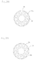
magnetic body 60 and the slot is carried out by the above stated manner. - Each of Fig. 11A and Fig. 11B shows a view of a formation example in which using the
iron core element 13 explained in Fig. 11A a two-pole, a four-pole, a six-pole and a twelve-pole of a rotor magnet iron core. For example, in a case where only the magnetic body is used according to the pole number to be used the manner of the magnetic short circuit between the magnetic poles changes and then the magnetic field of the air gap can be changed largely. - Further, when the magnetic shunt steel is employed, during the low temperature such as the start time since it works as the magnetic body, then it exhibits the effect for weakening the magnetic field of the air gap. However, when the temperature is arisen under the operation state it can not work as the magnetic body and it returns to the state in which the magnetic field is not adjusted, accordingly it is valid to lower only the start torque.
- When the minute adjustment in the magnetic filed is carried out, to between and the intermediate portion of the
magnetic body 70 and themagnetic shunt steel 70a and theiron core 13 thenon-magnetic body 70b may be inserted and then the adjustment is carried out. - Each of from Fig. 12A to Fig. 12D shows an example in which the end portion members of the axial direction of the
iron core 13 in Fig. 12B of the magnet rotor 2b of Fig. 12A are replace with the magnetic shunt steel 13b having the same shape of the iron cores 13a in which a cut-off portion is provided on the portion facing to the air gap shown in Fig. 12C and theiron core 13 and the non-magnetic body 13c. - According to the mutual action between the end portion of the skew groove of a
skew ring 80, which is provided on the outer face of the rotor shown in Fig. 12D and is made by the magnetic body, and a skew ring 80a having a cut portion which is cut off to obtain further the skew effect, the skew effect is increased further. - Each of Fig. 13A and Fig. 13B shows an example in which using a space of the
magnets 14b which is inserted the slots a between theskewed iron cores 13 of the four-pole rotor shown in Fig. 13A, and to obtain further the skew effect, the magnets are replaced with themagnets 14b shown in Fig. 13B. The magnets 14c thinner than themagnet 14b and the wedge shapemagnetic body 60b are combined and not to generate the gap they are inserted into the slots a, accordingly against a skew width W1 in the prior art a larger width W2 is obtained. - Each of Fig. 14A, Fig. 14B and Fig. 14C shows an example of a magnet rotor and a stator in which within a thickness of the
iron cores magnets - With this constitution, the delicate skew effect is carried out without the skewing and the strong and the distribution of the magnetic flux in the air gap are carried out and it can assemble simply with the low cost. The magnet is carried out the module performance in the minimum unit and only a single number it can use to much amounts, and the production cost of the magnet used in the single number is reduced about 1/6 degree.
- This is the epoch-making idea which can be correspond to the production of the various range machine and apparatus kinds having the different size capacities and the quantity of the mounts.
Reference numeral 81a denotes a non-magnetic body spacer. Fig. 14C is a cross-sectional view of the rotor. - Figs. 15A-15B and Figs. 16A-16C show examples of a magnet rotor and a magnet stator in which using the module and divided
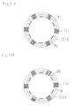
iron cores - Firstly, Figs. 15A and Fig. 15B will be explained. Fig. 15A shows an example of four-pole rotor and the rotor is constituted by the
module iron core 13f, themagnet 14f and thenon-magnetic body 81b etc. and the rotor of an inner rotation type electric rotating machine and the stator of an outer rotation type electric rotating machine are exemplified. - Fig. 15B shows an example in which using the
module iron core 13f and themagnet 14f, the rotor having the large capacity about two times of the outer diameter and the stator are formed. - According to the magnet, the magnetic body 60c and the magnetic shunt steel etc., the space in the slot which is formed between two
magnets 14f is buried and the loss in the magnetic field is prevented. - Next, Figs. 16A-16C will be explained. Fig. 16A shows the
module iron core 13 used for the rotor and the stator of a twelve-pole electric rotating machine, and Fig. 16B shows an example of the magnet rotor and the magnet stator in which the twenty-fouriron cores 13 are used.Reference numeral 14g denotes a magnet,reference numeral 60e denotes a magnetic body, etc.. - Fig. 16C shows an example of the construction of the
magnet 14g and it is constituted by a single magnet or plural magnets such as three numbers or four numbers. In the case of a large size machine, by dividing lengthily and laterally and then the work performance is increased. - Each of from Fig. 17A to Fig. 17D shows an example in which, to improve the heat withstanding performance about two times in comparison with that of the prior art, an outer skin of the
coil wire member 36 shown in Fig. 17A is covered by the heat withstanding member such as the alumina, the silica, and the silicone rubber, etc.. Fig. 17B shows an example of alayer 85 in which the outer skin of the alumina wire member is treated by the eloxation processing. - Fig. 17C shows an example in which to the wire 35a on which an eloxation film 85a is formed to increase further the insulating strength plural films 65b are formed using the same material and other materials. Fig. 17D shows an example in which to the outer skin of the
wire member 35b after the silicone resin having the protein structure bridge etc. (under the nitrogen atmosphere and under the temperature of 1000 °C, the reduction rate is 5 %) have covered, the alumina and the silica are covered and the flexibility of the wire member is increased remarkably and at the same time the heat withstanding performance is obtained. -
Reference numeral 35 denotes a wire member andreference numeral 85c denotes the heat withstanding resin such as the silicone resin andreference numeral 85d denotes a heat withstanding electric insulating body which is made by the alumina and the silica. The wire member having the good flexibility has the effects in which the electric wiring work of the winding wire etc. is carried out easily and it can endure fully against the vibration during the use time and the impact. - Each of Fig. 18A and Fig. 18B shows an example in which the air gap g1 between the
stator iron core 23 having the several time winding slots in comparison with that of the prior art in which the start torque (1 gm) and the cogging are formed in the minimum or is not haven and the rotor 2a is formed wider at the 2-2.5 times of the air gap g2 between thestator iron core 23a and the rotor 2b shown in Fig. 18B. - To compensate the output which is reduced according to the air gap increase and the magnet strength adjustment by the increase of the winding wire, the
slot 51 of the stator is formed larger and the minimum start torque and the efficiency during the low speed output time is increased remarkably (more than 95 %) and then such an electric rotating machine is realized. - In the above case, since the large inertia is given to the rotation system, the efficiency is improved further near to 100 %.
Reference numeral 52 denotes a slot of the stator iron core in the conventional type, reference numeral 2b denotes a shaft. - Fig. 19A shows an example in which to shift in phase the respective poles in the arrangement of the slot of the stator one portion of a width Wa of teeth portions of the electromagnet iron core 23b is formed wider than a width Wb of the other teeth portions.
- Further, Fig. 19B an example in which to shift in phase the respective poles in the arrangement of the slot of the stator one portion of a width Wc of teeth portions of the electromagnet iron core 23b is formed narrower than a width Wd of the other teeth portions.
- Accordingly, without the formations of the skew of the rotor and the unbalance of the magnet arrangement the low start torque is realized and the efficiency during the low speed and the low output is improved remarkably (more than 95 %) and then the electric rotating machine having the very small vibration noises is realized.
- In particular, it is effective to the magnet type rotor.
Reference numeral 53 denotes slots to which the winding is inserted. Reference numerals 2c and 2d denote rotors, and reference numeral g1 denotes an air gap. - Fig. 20A shows an example in which to shift in phase the respective poles in the arrangement of the slot of the stator one portion of a width We of the slit between adjacent
magnet iron cores 13g is formed wider than a width Wf of the other slits. - Fig. 20B shows an example in which to shift in phase the respective poles in the arrangement of the slot of the stator one portion of a width Wg of the slit between adjacent
magnet iron cores 13h is formed narrow than a width Wh of the other slits. - Accordingly, without the formations of the skew of the stator and the unbalance of the magnet pole arrangement the low start torque is realized and the efficiency during the low speed and the low output is improved remarkably (more than 95 %) and then the electric rotating machine having the very small vibration noises is realized.
- In particular, it is effective to the magnet type rotor and it is effective to apply the iron core of the wound motor and a cage type rotor of the induction machine and to the integral type iron core.
- Fig. 21A shows an example in which in which to shift in phase the respective magnetic poles of the arrangement of the bobbin winding type stator one portion of a width Wi between teeth portions of the
electromagnet iron core 22e is formed wider than a width Wj between the other teeth portions. - Fig. 21B shows an example in which in which to shift in phase the respective magnetic poles of the arrangement of the bobbin winding type stator one portion of a width Wk between teeth portions of the
electromagnet iron core 22e is formed narrow than a width W1 between the other teeth portions. - Accordingly, without the formations of the skew of the stator and the unbalance of the magnet pole arrangement the low start torque is realized and the efficiency during the low speed and the low output is improved remarkably (more than 95 %) and then the electric rotating machine having the very small vibration noises is realized.
- In particular, it is effective to the magnet type rotor. As one manner for realizing this, it can realize simply by altering the length of one circumferential direction of the magnet iron core 22f4.
- The present invention can apply in addition to the above stated various kinds machine and apparatuses to the other kinds electric rotating machines and also to the other embodiments different machine and apparatuses, such as a pancake type electric machine, a linear motor, an electromagnet machine and apparatus.
Claims (11)
- A single-phase electric rotating machine and an electromagnetic machine and apparatus having a single-phase iron core being applied to a bobbin type winding, wherein
among plural iron cores, a relative angle of a part or all of magnetic poles is altered from zero degree to several degrees;
thereby a voltage adjustment and an output adjustment are carried out by keeping pace of a series state and a parallel state of the winding and a change-over a tap. - An electric rotating machine and an electromagnetic machine and apparatus having a bobbin type winding electromagnet structure, wherein
from two-pole to N pole is altered freely by an installation manner of a magnetic pole piece. - An electromagnet structure having an iron core used in a bobbin type winding, wherein
to reduce an eddy current of an iron core in a pole piece and a york portion, said iron core is constituted by one selected from a surrounding metal fittings and a lamination iron core, an iron core constituted by a thin wire member, a vessel and a ferro-powdered iron core, and a thick material having plural thin grooves. - An electric rotating machine and an electromagnetic machine and apparatus having an iron core which is constituted integrally in an inner peripheral direction of an iron core used in a bobbin winding, wherein
to lessen a magnetism of resistance gone across between pole pieces of different poles, in a part of a york portion, said iron core is constituted by one selected from a surrounding metal fittings and a lamination iron core, an iron core constituted by a thin wire member, a vessel and a ferro-powdered iron core, and a thick material having plural thin grooves. - An electric rotating machine and an electromagnetic machine and apparatus having a bobbin winding iron core, wherein
to make smoothly a flow of magnetic field of mutual poles said iron core is arranged in a radial direction and is combined with a wedge shape iron core. - An electric rotating machine and an electromagnetic machine and apparatus comprising a magnet type stator having a module and divided iron core or a magnet type rotor having a module and divided iron core, wherein
from two-pole to N pole is altered freely according to a magnet insertion manner, and
a characteristic is altered freely according to a construction alternation of a strength and a cancellation using a magnetic body including a magnet, a magnetic shunt steel and a non-magnetic body. - An electric rotating machine and an electromagnetic machine and apparatus comprising a magnet type stator having a module and divided iron core or a magnet type rotor having a module and divided iron core, wherein
a start adjustment or a characteristic adjustment is carried out by one selected from a short-circuit ring and a bridge using a magnetic body including a magnetic shunt steel and a non-magnetic body. - An electric rotating machine and an electromagnetic machine and apparatus having a module and divided iron core, wherein
by replacing a cut-off portion with a non-magnetic body in a part of said divided iron core core, a cut-off shaped skew groove of said divided iron core is carried out to function effectively a skew effect. - An electric rotating machine and an electromagnetic machine and apparatus having a magnet insertion space of an iron core in which a skew is formed by mounting a magnet, wherein
using said magnet insertion space to form the skew a magnet and an opened space are combined with a wedge shape magnetic body;
thereby the skew effect is arisen further. - An electric rotating machine and an electromagnetic machine and apparatus comprising a zigzag shape iron core which has formed a skew effect using a magnetic pole iron core, wherein
to not generate a magnetic short circuit between adjacent mutual iron cores, using only said delicate zigzag iron core a skewing is omitted. - An electric rotating machine and an electromagnetic machine and apparatus having a magnet type rotor or a magnet type stator, wherein
an iron core for constituting a skew unit and a single or plural module thin magnets are combined;
thereby a skew formation is carried out.
Applications Claiming Priority (2)
| Application Number | Priority Date | Filing Date | Title |
|---|---|---|---|
| JP2001261406 | 2001-08-30 | ||
| JP2001261406 | 2001-08-30 |
Publications (2)
| Publication Number | Publication Date |
|---|---|
| EP1289097A2 true EP1289097A2 (en) | 2003-03-05 |
| EP1289097A3 EP1289097A3 (en) | 2003-05-21 |
Family
ID=19088459
Family Applications (1)
| Application Number | Title | Priority Date | Filing Date |
|---|---|---|---|
| EP02255975A Withdrawn EP1289097A3 (en) | 2001-08-30 | 2002-08-28 | Electric machine with toroidal coils |
Country Status (4)
| Country | Link |
|---|---|
| US (1) | US6933646B2 (en) |
| EP (1) | EP1289097A3 (en) |
| KR (1) | KR100904027B1 (en) |
| HK (1) | HK1055646A1 (en) |
Cited By (6)
| Publication number | Priority date | Publication date | Assignee | Title |
|---|---|---|---|---|
| WO2007063369A2 (en) * | 2005-11-29 | 2007-06-07 | High Technology Investments, B.V. | Core plate stack assembly for permanent magnet rotor of rotating machines |
| US7755241B2 (en) | 2005-03-31 | 2010-07-13 | Hans-Peter Wyremba | Electrical machine |
| US7808149B2 (en) | 2004-09-20 | 2010-10-05 | Wilic S.Ar.L. | Generator/electric motor, in particular for wind power plants, cable controlled plants or for hydraulic plants |
| DE202010015364U1 (en) | 2010-11-11 | 2012-02-17 | Hans-Peter Wyremba | Brushless electric motor or generator in shell construction |
| FR2969854A1 (en) * | 2010-12-22 | 2012-06-29 | Fed Mogul Sintertech | HOMOPOLAR MACHINE. |
| US20130057103A1 (en) * | 2011-09-07 | 2013-03-07 | Samsung Electronics Co., Ltd. | Motor and washing machine having the same |
Families Citing this family (28)
| Publication number | Priority date | Publication date | Assignee | Title |
|---|---|---|---|---|
| ITBZ20010043A1 (en) | 2001-09-13 | 2003-03-13 | High Technology Invest Bv | ELECTRIC GENERATOR OPERATED BY WIND ENERGY. |
| JP2004056394A (en) * | 2002-07-18 | 2004-02-19 | Fujitsu Ltd | Control apparatus for controlling capturing apparatus and storage apparatus via lan, capturing apparatus for the same, storage apparatus, program, and method |
| JP2006060915A (en) * | 2004-08-19 | 2006-03-02 | Toyota Industries Corp | Armature of electric motor |
| US7946591B2 (en) | 2005-09-21 | 2011-05-24 | Wilic S.Ar.L. | Combined labyrinth seal and screw-type gasket bearing sealing arrangement |
| ITBZ20050062A1 (en) | 2005-11-29 | 2007-05-30 | High Technology Invest Bv | PERMANENT MAGNET ROTOR FOR GENERATORS AND ELECTRIC MOTORS |
| KR100784220B1 (en) * | 2007-05-08 | 2007-12-10 | 김영국 | A coil of electromagnetic |
| ITMI20081122A1 (en) | 2008-06-19 | 2009-12-20 | Rolic Invest Sarl | WIND GENERATOR PROVIDED WITH A COOLING SYSTEM |
| KR100972176B1 (en) * | 2008-07-07 | 2010-07-23 | 허봉구 | Light guide plate and diffusion plate processing apparatus and processing method thereof |
| IT1390758B1 (en) | 2008-07-23 | 2011-09-23 | Rolic Invest Sarl | WIND GENERATOR |
| IT1391939B1 (en) | 2008-11-12 | 2012-02-02 | Rolic Invest Sarl | WIND GENERATOR |
| IT1391770B1 (en) | 2008-11-13 | 2012-01-27 | Rolic Invest Sarl | WIND GENERATOR FOR THE GENERATION OF ELECTRICITY |
| IT1392804B1 (en) | 2009-01-30 | 2012-03-23 | Rolic Invest Sarl | PACKAGING AND PACKAGING METHOD FOR POLE OF WIND GENERATORS |
| IT1393937B1 (en) | 2009-04-09 | 2012-05-17 | Rolic Invest Sarl | WIND TURBINE |
| IT1393707B1 (en) | 2009-04-29 | 2012-05-08 | Rolic Invest Sarl | WIND POWER PLANT FOR THE GENERATION OF ELECTRICITY |
| IT1394723B1 (en) | 2009-06-10 | 2012-07-13 | Rolic Invest Sarl | WIND POWER PLANT FOR THE GENERATION OF ELECTRICITY AND ITS CONTROL METHOD |
| IT1395148B1 (en) | 2009-08-07 | 2012-09-05 | Rolic Invest Sarl | METHOD AND APPARATUS FOR ACTIVATION OF AN ELECTRIC MACHINE AND ELECTRIC MACHINE |
| IT1397081B1 (en) | 2009-11-23 | 2012-12-28 | Rolic Invest Sarl | WIND POWER PLANT FOR THE GENERATION OF ELECTRICITY |
| IT1398060B1 (en) | 2010-02-04 | 2013-02-07 | Wilic Sarl | PLANT AND METHOD OF COOLING OF AN ELECTRIC GENERATOR OF AN AIR SPREADER, AND AIRCONDITIONER INCLUDING SUCH A COOLING PLANT |
| IT1399201B1 (en) | 2010-03-30 | 2013-04-11 | Wilic Sarl | AEROGENERATOR AND METHOD OF REMOVING A BEARING FROM A AIRCONDITIONER |
| IT1399511B1 (en) | 2010-04-22 | 2013-04-19 | Wilic Sarl | ELECTRIC GENERATOR FOR A VENTILATOR AND AEROGENER EQUIPPED WITH THIS ELECTRIC GENERATOR |
| ITMI20110375A1 (en) | 2011-03-10 | 2012-09-11 | Wilic Sarl | WIND TURBINE |
| ITMI20110377A1 (en) | 2011-03-10 | 2012-09-11 | Wilic Sarl | ROTARY ELECTRIC MACHINE FOR AEROGENERATOR |
| ITMI20110378A1 (en) | 2011-03-10 | 2012-09-11 | Wilic Sarl | ROTARY ELECTRIC MACHINE FOR AEROGENERATOR |
| US9979248B2 (en) | 2015-06-29 | 2018-05-22 | General Electric Company | Short circuit fault tolerant permanent magnet machine |
| JP2017169343A (en) * | 2016-03-16 | 2017-09-21 | 株式会社東芝 | Rotary electric machine, hoisting machine, and elevator |
| CA3031369A1 (en) * | 2016-07-20 | 2018-01-25 | Dumitru Bojiuc | Variable magnetic monopole field electro-magnet and inductor |
| KR101836297B1 (en) * | 2016-10-17 | 2018-03-08 | 현대자동차 주식회사 | Driving motor |
| ES2952947T3 (en) * | 2017-06-06 | 2023-11-07 | Ge Renewable Tech Wind Bv | Magnet module and electrical machine |
Citations (11)
| Publication number | Priority date | Publication date | Assignee | Title |
|---|---|---|---|---|
| GB769043A (en) * | 1954-05-13 | 1957-02-27 | Bbc Brown Boveri & Cie | Single-phase commutator motor for direct traction drives |
| GB2062977A (en) * | 1979-11-10 | 1981-05-28 | Northern Eng Ind | Alternator |
| DE3401163A1 (en) * | 1983-05-02 | 1984-11-08 | Weh, Herbert, Prof. Dr.-Ing., 3300 Braunschweig | Electrical machines having permanent-magnet excitation, and as a reluctance version in a laminated excitation arrangement |
| US4712035A (en) * | 1985-11-12 | 1987-12-08 | General Electric Company | Salient pole core and salient pole electronically commutated motor |
| EP0412201A1 (en) * | 1989-08-11 | 1991-02-13 | Siemens Aktiengesellschaft | Single-phase asynchronous motor |
| US5382862A (en) * | 1992-07-20 | 1995-01-17 | General Motors Corporation | Alternating current generator rotor |
| DE19547159A1 (en) * | 1994-12-21 | 1996-06-27 | Wolfgang Hill | Transverse flux machine with rotor parts within soft magnetic body |
| US5726514A (en) * | 1995-11-28 | 1998-03-10 | Voith Turbo Gmbh & Co. Kg | Circuit arrangement for energizing a two-phase electric machine |
| DE19757502A1 (en) * | 1997-12-23 | 1999-06-24 | Vlado Dr Ostovic | Electric machine with permanent magnet excitation |
| EP1052761A2 (en) * | 1999-05-06 | 2000-11-15 | Yukio Kinoshita | A rotary electric machine |
| WO2001054255A1 (en) * | 2000-01-20 | 2001-07-26 | Pacsci Motion Control, Inc. | Direct drive toroidally wound dc brushless motor |
Family Cites Families (24)
| Publication number | Priority date | Publication date | Assignee | Title |
|---|---|---|---|---|
| US452717A (en) * | 1891-05-19 | Andrew l | ||
| US1905660A (en) * | 1929-05-03 | 1933-04-25 | Platen Baltzar Carl Von | Electric machine |
| US2243318A (en) * | 1937-11-01 | 1941-05-27 | Rawlings George William | Laminated magnetic element |
| DE2249729A1 (en) * | 1972-10-11 | 1974-04-25 | Binder Magnete | STEPPER MOTOR |
| US4355248A (en) * | 1981-07-21 | 1982-10-19 | Imc Magnetics Corp. | Stepper motor |
| US4824734A (en) * | 1983-06-02 | 1989-04-25 | Kawasaki Steel Corp. | Tin-containing iron base powder and process for making |
| JPS63124750A (en) * | 1986-11-13 | 1988-05-28 | Tamagawa Seiki Co Ltd | Brushless dc motor |
| US5274291A (en) * | 1990-01-08 | 1993-12-28 | Clarke Patrick W | Rotary transformer with multiple angularly adjustable stators |
| US5194773A (en) * | 1990-01-08 | 1993-03-16 | Clarke Patrick W | Adjustable speed split stator rotary machine |
| JPH04285444A (en) * | 1991-03-12 | 1992-10-09 | Fujitsu General Ltd | Stator core of motor |
| JPH0670532A (en) * | 1992-06-24 | 1994-03-11 | Oriental Motor Co Ltd | Stepping motor |
| JPH0636923A (en) * | 1992-07-20 | 1994-02-10 | Railway Technical Res Inst | Ground coil |
| JPH10108427A (en) * | 1996-09-26 | 1998-04-24 | Kokusan Denki Co Ltd | Power supply in inrtenal combustion engine |
| US5890277A (en) * | 1996-11-04 | 1999-04-06 | General Electric Company | Method for manufacturing a claw pole stator structure |
| JP3131403B2 (en) * | 1997-04-07 | 2001-01-31 | 日本サーボ株式会社 | Stepping motor |
| JP3548425B2 (en) * | 1998-04-17 | 2004-07-28 | キヤノン株式会社 | motor |
| JP3421251B2 (en) * | 1998-08-21 | 2003-06-30 | ミネベア株式会社 | Rotating electric machine and its bobbin |
| JP3242635B2 (en) * | 1999-01-28 | 2001-12-25 | 三菱電機株式会社 | Alternator |
| JP2000308288A (en) * | 1999-04-20 | 2000-11-02 | Yukio Kinoshita | Magnet-type motor and generator |
| JP3555016B2 (en) * | 1999-06-08 | 2004-08-18 | 幸雄 木下 | Rotating electric machines and electromagnetic devices using magnets |
| JP3774821B2 (en) * | 1999-05-06 | 2006-05-17 | 株式会社Inp技術研究所 | Rotating electric machine and electromagnetic equipment using bobbin type electromagnet |
| JP2001169497A (en) * | 1999-12-06 | 2001-06-22 | Moriyama Manufacturing Co Ltd | Stator for ac generator |
| JP2001186733A (en) * | 1999-12-27 | 2001-07-06 | Fujitsu General Ltd | Induction motor |
| JP3790438B2 (en) * | 2001-05-07 | 2006-06-28 | 建準電機工業股▲分▼有限公司 | Improved structure of stator assembly of electric motor |
-
2002
- 2002-08-28 EP EP02255975A patent/EP1289097A3/en not_active Withdrawn
- 2002-08-29 US US10/230,298 patent/US6933646B2/en not_active Expired - Fee Related
- 2002-08-29 KR KR1020020051546A patent/KR100904027B1/en not_active IP Right Cessation
-
2003
- 2003-09-05 HK HK03106323.2A patent/HK1055646A1/en unknown
Patent Citations (11)
| Publication number | Priority date | Publication date | Assignee | Title |
|---|---|---|---|---|
| GB769043A (en) * | 1954-05-13 | 1957-02-27 | Bbc Brown Boveri & Cie | Single-phase commutator motor for direct traction drives |
| GB2062977A (en) * | 1979-11-10 | 1981-05-28 | Northern Eng Ind | Alternator |
| DE3401163A1 (en) * | 1983-05-02 | 1984-11-08 | Weh, Herbert, Prof. Dr.-Ing., 3300 Braunschweig | Electrical machines having permanent-magnet excitation, and as a reluctance version in a laminated excitation arrangement |
| US4712035A (en) * | 1985-11-12 | 1987-12-08 | General Electric Company | Salient pole core and salient pole electronically commutated motor |
| EP0412201A1 (en) * | 1989-08-11 | 1991-02-13 | Siemens Aktiengesellschaft | Single-phase asynchronous motor |
| US5382862A (en) * | 1992-07-20 | 1995-01-17 | General Motors Corporation | Alternating current generator rotor |
| DE19547159A1 (en) * | 1994-12-21 | 1996-06-27 | Wolfgang Hill | Transverse flux machine with rotor parts within soft magnetic body |
| US5726514A (en) * | 1995-11-28 | 1998-03-10 | Voith Turbo Gmbh & Co. Kg | Circuit arrangement for energizing a two-phase electric machine |
| DE19757502A1 (en) * | 1997-12-23 | 1999-06-24 | Vlado Dr Ostovic | Electric machine with permanent magnet excitation |
| EP1052761A2 (en) * | 1999-05-06 | 2000-11-15 | Yukio Kinoshita | A rotary electric machine |
| WO2001054255A1 (en) * | 2000-01-20 | 2001-07-26 | Pacsci Motion Control, Inc. | Direct drive toroidally wound dc brushless motor |
Cited By (9)
| Publication number | Priority date | Publication date | Assignee | Title |
|---|---|---|---|---|
| US7808149B2 (en) | 2004-09-20 | 2010-10-05 | Wilic S.Ar.L. | Generator/electric motor, in particular for wind power plants, cable controlled plants or for hydraulic plants |
| US7755241B2 (en) | 2005-03-31 | 2010-07-13 | Hans-Peter Wyremba | Electrical machine |
| EP1708338B1 (en) * | 2005-03-31 | 2011-05-04 | Hans-Peter Wyremba | Electric machine |
| WO2007063369A2 (en) * | 2005-11-29 | 2007-06-07 | High Technology Investments, B.V. | Core plate stack assembly for permanent magnet rotor of rotating machines |
| WO2007063369A3 (en) * | 2005-11-29 | 2007-08-30 | High Technology Investments B | Core plate stack assembly for permanent magnet rotor of rotating machines |
| DE202010015364U1 (en) | 2010-11-11 | 2012-02-17 | Hans-Peter Wyremba | Brushless electric motor or generator in shell construction |
| DE102010054847A1 (en) | 2010-11-11 | 2012-05-16 | Hans-Peter Wyremba | Brushless electric motor or generator in shell construction |
| FR2969854A1 (en) * | 2010-12-22 | 2012-06-29 | Fed Mogul Sintertech | HOMOPOLAR MACHINE. |
| US20130057103A1 (en) * | 2011-09-07 | 2013-03-07 | Samsung Electronics Co., Ltd. | Motor and washing machine having the same |
Also Published As
| Publication number | Publication date |
|---|---|
| KR100904027B1 (en) | 2009-06-22 |
| KR20030019206A (en) | 2003-03-06 |
| EP1289097A3 (en) | 2003-05-21 |
| HK1055646A1 (en) | 2004-01-16 |
| US20030042815A1 (en) | 2003-03-06 |
| US6933646B2 (en) | 2005-08-23 |
Similar Documents
| Publication | Publication Date | Title |
|---|---|---|
| US6933646B2 (en) | Electric rotating machine and electromagnetic machine and apparatus | |
| EP1193845B1 (en) | Hybrid synchronous motor equipped with annular winding | |
| EP0823771B1 (en) | Motor | |
| EP1416619B1 (en) | Hybrid synchronous electric machine | |
| US6628031B2 (en) | Harmonic-frequency synchronous machine with flux concentration | |
| US6617739B1 (en) | Rotary electric machine | |
| US11594929B2 (en) | Axial flux motor with distributed winding | |
| US20180123434A1 (en) | Rotor, stator and motor | |
| JP3535485B2 (en) | Three-phase hybrid type stepping motor | |
| JP3442636B2 (en) | Permanent magnet motor | |
| WO2018037529A1 (en) | Rotary electric machine | |
| JP2003153472A (en) | Electric rotating machine and electromagnetic apparatus | |
| JP4415176B2 (en) | Induction motor having a ring-shaped stator coil | |
| KR20080012811A (en) | Dynamoelectric machine rotor and method for reducing torque ripple | |
| JP3422643B2 (en) | Synchronous motor | |
| JP4482918B2 (en) | Permanent magnet type electric motor having ring-shaped stator coil | |
| CN114552836A (en) | Rotating electrical machine | |
| RU2246167C1 (en) | Face-type electrical machine | |
| US20220085674A1 (en) | Rotary electric machine | |
| JP3797488B2 (en) | Multi-pole rotating electric machine | |
| RU2246168C1 (en) | Face-type electrical machine | |
| KR102504873B1 (en) | Double air gap Surface Permanent Magnet Synchronous Motor with 2 controllers | |
| WO2023218743A1 (en) | Rotor and ipm motor having same | |
| JP6641520B2 (en) | Rotary electric machine control device, rotary electric machine, and control method for rotary electric machine | |
| JP2010504078A (en) | Synchronous machine |
Legal Events
| Date | Code | Title | Description |
|---|---|---|---|
| PUAI | Public reference made under article 153(3) epc to a published international application that has entered the european phase |
Free format text: ORIGINAL CODE: 0009012 |
|
| AK | Designated contracting states |
Kind code of ref document: A2 Designated state(s): AT BE BG CH CY CZ DE DK EE ES FI FR GB GR IE IT LI LU MC NL PT SE SK TR Designated state(s): AT BE BG CH CY CZ DE DK EE ES FI FR GB GR IE IT LI LU MC NL PT SE SK TR |
|
| AX | Request for extension of the european patent |
Extension state: AL LT LV MK RO SI |
|
| PUAL | Search report despatched |
Free format text: ORIGINAL CODE: 0009013 |
|
| RIC1 | Information provided on ipc code assigned before grant |
Ipc: 7H 02K 1/02 B Ipc: 7H 02K 21/22 B Ipc: 7H 02K 1/22 B Ipc: 7H 02K 1/27 B Ipc: 7H 02K 1/14 B Ipc: 7H 02K 3/28 A |
|
| AK | Designated contracting states |
Designated state(s): AT BE BG CH CY CZ DE DK EE ES FI FR GB GR IE IT LI LU MC NL PT SE SK TR |
|
| AX | Request for extension of the european patent |
Extension state: AL LT LV MK RO SI |
|
| 17P | Request for examination filed |
Effective date: 20031209 |
|
| AKX | Designation fees paid |
Designated state(s): DE FR GB |
|
| 17Q | First examination report despatched |
Effective date: 20070821 |
|
| STAA | Information on the status of an ep patent application or granted ep patent |
Free format text: STATUS: THE APPLICATION IS DEEMED TO BE WITHDRAWN |
|
| 18D | Application deemed to be withdrawn |
Effective date: 20090303 |
|
| REG | Reference to a national code |
Ref country code: HK Ref legal event code: WD Ref document number: 1055646 Country of ref document: HK |