EP1288763A2 - Apparatus for controlling an agricultural vehicle - Google Patents
Apparatus for controlling an agricultural vehicle Download PDFInfo
- Publication number
- EP1288763A2 EP1288763A2 EP02018503A EP02018503A EP1288763A2 EP 1288763 A2 EP1288763 A2 EP 1288763A2 EP 02018503 A EP02018503 A EP 02018503A EP 02018503 A EP02018503 A EP 02018503A EP 1288763 A2 EP1288763 A2 EP 1288763A2
- Authority
- EP
- European Patent Office
- Prior art keywords
- control element
- function
- control
- selection
- switch
- Prior art date
- Legal status (The legal status is an assumption and is not a legal conclusion. Google has not performed a legal analysis and makes no representation as to the accuracy of the status listed.)
- Granted
Links
Images


Classifications
-
- G—PHYSICS
- G05—CONTROLLING; REGULATING
- G05G—CONTROL DEVICES OR SYSTEMS INSOFAR AS CHARACTERISED BY MECHANICAL FEATURES ONLY
- G05G1/00—Controlling members, e.g. knobs or handles; Assemblies or arrangements thereof; Indicating position of controlling members
- G05G1/58—Rests or guides for relevant parts of the operator's body
-
- G—PHYSICS
- G05—CONTROLLING; REGULATING
- G05G—CONTROL DEVICES OR SYSTEMS INSOFAR AS CHARACTERISED BY MECHANICAL FEATURES ONLY
- G05G9/00—Manually-actuated control mechanisms provided with one single controlling member co-operating with two or more controlled members, e.g. selectively, simultaneously
- G05G9/02—Manually-actuated control mechanisms provided with one single controlling member co-operating with two or more controlled members, e.g. selectively, simultaneously the controlling member being movable in different independent ways, movement in each individual way actuating one controlled member only
- G05G9/04—Manually-actuated control mechanisms provided with one single controlling member co-operating with two or more controlled members, e.g. selectively, simultaneously the controlling member being movable in different independent ways, movement in each individual way actuating one controlled member only in which movement in two or more ways can occur simultaneously
- G05G9/047—Manually-actuated control mechanisms provided with one single controlling member co-operating with two or more controlled members, e.g. selectively, simultaneously the controlling member being movable in different independent ways, movement in each individual way actuating one controlled member only in which movement in two or more ways can occur simultaneously the controlling member being movable by hand about orthogonal axes, e.g. joysticks
- G05G2009/04774—Manually-actuated control mechanisms provided with one single controlling member co-operating with two or more controlled members, e.g. selectively, simultaneously the controlling member being movable in different independent ways, movement in each individual way actuating one controlled member only in which movement in two or more ways can occur simultaneously the controlling member being movable by hand about orthogonal axes, e.g. joysticks with additional switches or sensors on the handle
-
- H—ELECTRICITY
- H01—ELECTRIC ELEMENTS
- H01H—ELECTRIC SWITCHES; RELAYS; SELECTORS; EMERGENCY PROTECTIVE DEVICES
- H01H9/00—Details of switching devices, not covered by groups H01H1/00 - H01H7/00
- H01H9/02—Bases, casings, or covers
- H01H9/06—Casing of switch constituted by a handle serving a purpose other than the actuation of the switch, e.g. by the handle of a vacuum cleaner
- H01H2009/066—Casing of switch constituted by a handle serving a purpose other than the actuation of the switch, e.g. by the handle of a vacuum cleaner having switches mounted on a control handle, e.g. gear shift lever
Definitions
- the invention relates to a device for controlling an agricultural vehicle, according to the preamble of claim 1.
- DE 196 19 419 A1 describes a device for controlling an agricultural Vehicle with a multi-function handle arranged in the driver's cab is known, on the handle part a plurality of controls are arranged.
- the Control element is used to set the first control functions, such as "Raise / lower cutting unit", which can only be operated using this control element are.
- the known device has a separate control panel with a associated with this electronic display unit, the control panel more Has control elements for setting further second control functions, that cannot be operated by the control elements of the multifunction handle.
- the Control functions that can be set using the controls on the control panel are in of the electronic display unit represented by function symbols, so that the Setting of the second control functions can be checked easily.
- first control functions associated with the multifunction handle that they are used relatively often by the operator.
- These second control functions include, for example, control functions that do not need to be done while driving.
- the object of the present invention is to provide a device for controlling a agricultural vehicle in such a way that the ease of use is further increased for the driver.
- the device according to the invention has the features of claim 1.
- the particular advantage of the device according to the invention is that with the provision of a selection / transfer control element an assignment of usually Control functions for the control elements of the multi-function handle that are rarely activated is made possible.
- Rarely actuated control functions of a harvesting machine, such as swiveling the grain tank pipe, adjusting the cutting table length or Setting the cutting angle cutting unit can be done easily by pressing a single selection / transfer control element on one or more control elements, which are preferably designed as multiple controls, des Multifunction handle can be transferred. After setting the desired one The vehicle driver can now perform the control function using the selection / transfer control element on the corresponding control element of the multifunction handle Actuate the corresponding control function without removing your hand from the multi-function handle would have to remove.
- the selection / transfer control element for example on the steering wheel or on the left armrest in an operating environment arranged by the driver so that he can do this with the left hand or with one foot can operate without removing the right hand from the multi-function handle would have to be removed.
- the selection / transfer control element also be attached to the multifunction handle itself, so that it can be operated only the right hand of the driver is required.
- the particular advantage of the device according to the invention according to claim 2 is that with a multi-control element of the multifunction handle not just a frequently used first control function of the multifunction handle itself, but also at least a relatively rare tax function of the remotely located control panel can be operated: by operating a selection / transfer control element, which is arranged on the multifunction handle, can a fixed assignment of the multiple control element to a first or second Control function can be established. This is done by actuating the selection / transfer control element no menu selection, for which the corresponding one Control function selected and secondly the selected control function is confirmed by pressing it again. According to the invention direct selection by actuating the selection / transfer control element the control function to the multiple control element, so that the selection and the The control function is confirmed at the same time. This will make the setting the corresponding control function is significantly simplified.
- the selection / transfer control element designed as a multiple switch, so that by actuating the same a single first control function and at least one second control function are adjustable.
- the position of the multiple switch in the first can be advantageous
- Control function be designed such that the multiple switch is different simplified to the position in the second control functions - this means in particular with less resistance - can be moved to the starting position.
- the multiple switch can be used as a rotary switch be formed, with function symbols assigned to the respective switching positions are for recognizing the respective switching position.
- the rotary switch can be designed as a knurled wheel be in some areas by the recess of a handle part of the multi-function handle protrudes and the control functions each rest positions assigned.
- the rest position of the assigned to the first control function Switch position is preferably formed stronger than the locking position of the second control function assigned switch position so that the operator also quickly and easily switch the switch back to that assigned to the first control function Switch position can be moved back.
- the locking positions of the rotary switch haptically perceptible, the different control functions preferably are perceptible differently. This way, without looking a desired setting of the control function is carried out on the multifunction handle become.
- the device according to the invention is used as an operating unit in agricultural Vehicles such as forage harvesters and combine harvesters.
- a forage harvester 30 is shown in FIG.
- the forage harvester 30 has a means Hydraulic cylinder 31 actuated supercharger manifold 32. Furthermore, the forage harvester 30 a pick-up connected to the chassis via a feed unit 33 34 on which a feed screw 35, roller hold-down 36 and a support wheel 37 are attached.
- the forage harvester 30 also has a driver's cab 38, in which a steering wheel 39 for steering the forage harvester 30 and a plurality of operating elements 40 are arranged to operate the aforementioned control functions.
- the controls 40, the electrical or electromechanical way also not shown Actuating units of the forage harvester 30 act as part of the invention Device.
- the device according to the invention essentially consists from a multifunction handle 1 and a selection / transfer control element 12, both of which are arranged in the driver's cab 38.
- the multi-function handle 1 is arranged at such a height that the vehicle driver controls it grasp with the right hand and the controls with a few Fingers can operate.
- the selection / transfer control element 12 can in the foot area as a foot switch 22, on the steering wheel 39, on the left armrest or on the multifunction handle 1 be arranged itself. Furthermore, the device according to the invention an electronic display unit 2 designed as a monitor and a control panel 3 include.
- the device according to the invention described below is used for actuation of control functions of a combine harvester. In the same way you can the actuation of corresponding control functions of the forage harvester described above 30 done.
- the multifunction handle 1 has a plurality of operating elements 4, 5, 6.
- the control element 4 is a multiple control element or a double control element educated.
- the multiple control element is elliptical and enables by actuation at opposite end areas with a relatively small radius, that a combine harvester’s cutting deck either raised or lowered becomes. This is indicated by the function symbols 9 designed as arrows.
- the on-off control element 5 can be seen, by means of which the cutting mechanism or can be switched off.
- the cutting mechanism or can be switched off there is an on button 5 'for switching on the cutting unit and on the other hand an off button 5 "for switching off of the cutting unit.
- a reel control control element is provided as a further control element 6, that - like the cutter control control 4 - as a multiple control is trained.
- a lifting and lowering of the reel causes: when actuated in areas of the control element 6, in the according to FIG Arrows oriented as function symbols 9 in the leaf plane to the left and to the right the reel is moved back and forth.
- the control elements 4, 5, 6 relate to a category of first control functions, which operates relatively often when driving the combine and while driving Need to become.
- the multiple controls 4, 6 are preferably as rocker or toggle switches educated.
- the controls 4, 5, 6 are in an upper area of a handle part 11 of the multi-function handle 1 arranged.
- the multi-function handle 1 is in a carrier housing 10 movably mounted so that the direction of travel and / or the driving speed the combine by pushing and pulling the multi-function handle 1 can be controlled.
- a further control element 12 is arranged on the handle part 11, which as Selection / transfer control element is formed.
- the selection / transfer control 12 has several switching positions (three switching positions), so that the assignment of the multiple control element 4 to the only first control function (Basic function), namely raising / lowering the cutting unit (SW), on the one hand and can be set to two further second control functions on the other hand.
- the Second control functions concern the setting. of actuators that are not common occur and usually by means of controls 13 of the control panel 3rd be made.
- the selection / transfer control element 12 formed as a rotary switch, the area through a slot-shaped recess protrudes from the handle part 11.
- This subarea 14 serves for detection and Rotating the selection / transfer control element 12, whereby by a circular Recess 15 on an upper side 16 of the handle part 11 the current switching position of the selection / transfer control element 12 is signaled.
- the signaling is supported by a lens 41, which is arranged in the region of the recess 15 is. In this way, the function symbol 17 can be shown enlarged.
- the desired control function is activated by pressing the knurled wheel Selection / transfer control element 12 causes, in a rest position, in the function symbol 17 symbolizing the control function in alignment with the Recess 15 is arranged, the desired control function is set.
- the Knurled wheel 12 has 3 function symbols 17 in the present exemplary embodiment , only a single one being visible through the recess 15. This visible function symbol 17 corresponds to the desired control function, the one with another control element 4 that fixed this selection / transfer control element 12 is assigned, can be operated.
- the selection / transfer control element can be set 12 the setting of two further control functions, namely on the one hand the "swivel the grain tank pipe” and the "cross swivel of the cutting unit ".
- the first control function lifting / lowering the cutting unit "is indicated by the function symbol SW (17).
- the first control function is "Raise / lower cutting unit" SW set.
- the knurled wheel 12 is haptically perceptible and points to the Circumferential surface on a corrugated surface structure 21.
- the actuation of the Knurled wheel 12 is latched, three to the control functions corresponding locking positions can be taken.
- the switching positions can be perceived differently by haptics, for example the shape of the protruding portion 14 in a switch position concave and convex in another switching position can be.
- this can also be provided with a stop, so that the operator always by turning back the control element 12 to the stop in the basic position can be brought in which the first control function can be set by the control element 4 is.
- the function symbols 17 of the control functions which are by means of the control element 12 are adjustable, on the top 16 of the handle part 11 in the corresponding Sequence of switch positions shown. This will make the driver signals which control functions can be set using the knurled wheel 12.
- the currently set control function results from that through the lens 41 and the recess 15 recognizable function symbol 17.
- the currently set control function can the function symbol 17, which in the Recess 15 is visible, be illuminated.
- this can be designed as a slide switch 42 which is linear in different Switching positions is movable.
- the slide switch 42 can, for example, two Have positions, in the first switching position an automatic mode and in a second switching position is manual operation of the control elements 5 and 6 actuable switching functions is set.
- the corresponding function symbols can be arranged in a row be, the control function corresponding by adjusting the slide switch to the corresponding function symbol.
- the function symbols can alternatively or can also be shown in the electronic display unit 2.
- a simple assignment of control functions to the control element 4 becomes possible made on the multi-function handle 1, wherein. the operator only the Must look at the ergonomically arranged monitor 2.
- the selection / transfer control element 12 is haptic is perceptible in order to make it easy to detect.
- the device according to the invention advantageously enables a large part of the Control functions that are otherwise arranged by remote control elements 13 can be actuated, transferred to the multifunction handle 1.
- the second is Control function immediately and directly a switching position of the selection / transfer control element 12 assigned.
- the selection / transfer control 43 is designed as a sliding element and serves to assign the control elements 4, 5 and / or 6 predetermined control functions.
- a first position of the control element 43 could be by pressing the Key 5 'to stop and reverse the feed unit 33.
- the second position of the control element 43 can be pressed by pressing the key 5 ' a pivoting of the roller hold-down device 36 simultaneously with the reversal respectively.
- the driver can advantageously operate individually before each reversal of the selection / transfer control element 43, which is more functional Context is desired without removing the hand from the multi-function handle 1 would have to be removed.
- the corresponding control elements 4, 5, 6 in a common are advantageous Level arranged on the handle part 11, so that it is simple by means of a Fingers are reachable.
- selection / transfer controls 12, 43 are for rare operations provided by control functions of the harvesting machine, for example grain tank pipe swivel, adjust cutting table length, manual cross-cutting device adjust or set cutting angle cutting unit.
- control functions of the harvesting machine for example grain tank pipe swivel, adjust cutting table length, manual cross-cutting device adjust or set cutting angle cutting unit.
- a selection / transfer control element 12, 43 directly setting values the harvester, which is also only set from time to time in work mode must be assigned to the controls 5, 6 or.
- the selection / transfer controls 12, 43 can on the one hand directly on Handle part 11 may be arranged. Alternatively, they can also be used in an operating environment of the driver can be arranged within the cabin 38, such as in the foot area. Multiple selection / transfer controls can be advantageous 12, 43 can be provided, each determined and fixed Controls 4, 5, 6 are assigned. This ensures that the vehicle driver preselectable by the selection / transfer controls 12, 43 Assign control functions to the relevant controls 4, 5, 6 can. This is advantageously achieved in that the selection / transfer control elements 12, 43 in close proximity to the corresponding ones Controls 4, 5, 6 are located. This functional link can also supported by markings, for example connecting lines, on the handle part 11 become.
Abstract
Description
Die Erfindung betrifft eine Vorrichtung zum Steuern eines landwirtschaftlichen Fahrzeugs, nach dem Oberbegriff des Patentanspruchs 1.The invention relates to a device for controlling an agricultural vehicle, according to the preamble of claim 1.
Aus der DE 196 19 419 A1 ist eine Vorrichtung zum Steuern eines landwirtschaftlichen Fahrzeugs mit einem in der Fahrerkabine angeordneten Multifunktionsgriff bekannt, an dessen Griffteil eine Mehrzahl von Bedienelementen angeordnet sind. Das Bedienelement dient zur Einstellung von ersten Steuerfunktionen, wie beispielsweise "Schneidwerk heben/senken", die nur mittels dieses Bedienelementes betätigbar sind. Weiterhin weist die bekannte Vorrichtung ein gesondertes Bedienpult mit einer diesem zugeordneten elektronischen Anzeigeeinheit auf, wobei das Bedienpult weitere Bedienelemente aufweist zur Einstellung von weiteren zweiten Steuerfunktionen, die nicht durch Bedienelemente des Multifunktionsgriffes betätigbar sind. Die durch die Bedienelemente des Bedienpults einstellbaren Steuerfunktionen sind in der elektronischen Anzeigeeinheit durch Funktionssymbole dargestellt, so dass die Einstellung der zweiten Steuerfunktionen einfach überprüft werden können. Um den Bedienungskomfort und die Betriebssicherheit der Vorrichtung zu erhöhen, sind die dem Multifunktionsgriff zugeordneten ersten Steuerfunktionen dadurch gekennzeichnet, dass sie relativ häufig von der Bedienperson eingesetzt werden. Dem gegenüber besteht bei der Kategorie von zweiten Steuerfunktionen, die durch eine Handbewegung der Bedienperson vom Multifunktionsgriff zum Bedienpult erfasst und betätigt werden können, nicht die Notwendigkeit eines häufigen Gebrauchs. Diese zweiten Steuerfunktionen beinhalten beispielsweise Steuerfunktionen, die nicht während der Fahrt vorgenommen werden müssen.DE 196 19 419 A1 describes a device for controlling an agricultural Vehicle with a multi-function handle arranged in the driver's cab is known, on the handle part a plurality of controls are arranged. The Control element is used to set the first control functions, such as "Raise / lower cutting unit", which can only be operated using this control element are. Furthermore, the known device has a separate control panel with a associated with this electronic display unit, the control panel more Has control elements for setting further second control functions, that cannot be operated by the control elements of the multifunction handle. The Control functions that can be set using the controls on the control panel are in of the electronic display unit represented by function symbols, so that the Setting of the second control functions can be checked easily. To the The ease of use and the operational reliability of the device are the characterized the first control functions associated with the multifunction handle, that they are used relatively often by the operator. Opposite exists in the category of second control functions by a The operator's hand movement from the multi-function handle to the control panel is recorded and can be operated, not the need for frequent use. These second control functions include, for example, control functions that do not need to be done while driving.
Zwar ist in der bekannten Vorrichtung am Multifunktionsgriff eine Menü-Bedientaste vorgesehen, mittels derer im Zusammenhang mit einem im Multifunktionsgriff integrierten Anzeigeelement den Bedienelementen des Multifunktionsgriffes unterschiedliche Steuerfunktionen zugewiesen werden können. Hierdurch kann die Anzahl der Bedienelemente an dem Multifunktionsgriff wesentlich reduziert werden. Nachteilig ist jedoch, dass zusätzlich in dem Multifunktionsgriff eine Anzeigeeinheit vorgesehen sein muss, die zur Gewährleistung der Betriebssicherheit erhöhten Sicherheitsanforderungen gerecht werden muss.There is a menu control button on the multifunction handle in the known device provided, by means of which in connection with an integrated in the multi-function handle Display element the controls of the multi-function handle different Control functions can be assigned. This allows the number of Controls on the multifunction handle can be significantly reduced. adversely is, however, that a display unit is additionally provided in the multifunction handle must be the increased safety requirements to ensure operational safety must do justice.
Aufgabe der vorliegenden Erfindung ist es, eine Vorrichtung zum Steuern eines landwirtschaftlichen Fahrzeuges derart weiterzubilden, dass der Bedienungskomfort für den Fahrzeugführer weiter erhöht wird.The object of the present invention is to provide a device for controlling a agricultural vehicle in such a way that the ease of use is further increased for the driver.
Zur Lösung dieser Aufgabe weist die erfindungsgemäße Vorrichtung die Merkmale des Patentanspruchs 1 auf.To achieve this object, the device according to the invention has the features of claim 1.
Der besondere Vorteil der erfindungsgemäßen Vorrichtung besteht darin, dass mit dem Vorsehen eines Auswahl/Übergabe-Bedienelementes eine Zuordnung von üblicherweise selten betätigbaren Steuerfunktionen zu Bedienelementen des Multifunktionsgriffes ermöglicht wird. Selten betätigbare Stellfunktionen einer Erntemaschine, wie beispielsweise Korntankrohr schwenken, Schneidwerktischlänge einstellen oder Schnittwinkel-Schneidwerk einstellen, können auf einfache Weise durch Betätigen eines einzigen Auswahl/Übergabe-Bedienelementes auf ein oder mehrere Bedienelemente, die vorzugsweise als Mehrfach-Bedienelemente ausgebildet sind, des Multifunktionsgriffs übertragen werden. Nach erfolgter Einstellung der gewünschten Steuerfunktion mittels des Auswahl/Übergabe-Bedienelementes kann nun der Fahrzeugführer an dem entsprechenden Bedienelement des Multifunktionsgriffes die entsprechende Steuerfunktion betätigen, ohne dass er die Hand von dem Multifunktionsgriff entfernen müsste. Dabei ist das Auswahl/Übergabe-Bedienelement beispielsweise am Lenkrad oder an der linken Armlehne in einem Betätigungsumfeld des Fahrzeugführers angeordnet, so dass er dieses mit der linken Hand oder mit einem Fuß betätigen kann, ohne dass die rechte Hand von dem Multifunktionsgriff entfernt werden müsste. Alternativ kann das Auswahl/Übergabe-Bedienelement auch an dem Multifunktionsgriff selbst angebracht sein, so dass zur Bedienung lediglich die rechte Hand des Fahrzeugführers erforderlich ist.The particular advantage of the device according to the invention is that with the provision of a selection / transfer control element an assignment of usually Control functions for the control elements of the multi-function handle that are rarely activated is made possible. Rarely actuated control functions of a harvesting machine, such as swiveling the grain tank pipe, adjusting the cutting table length or Setting the cutting angle cutting unit can be done easily by pressing a single selection / transfer control element on one or more control elements, which are preferably designed as multiple controls, des Multifunction handle can be transferred. After setting the desired one The vehicle driver can now perform the control function using the selection / transfer control element on the corresponding control element of the multifunction handle Actuate the corresponding control function without removing your hand from the multi-function handle would have to remove. The selection / transfer control element for example on the steering wheel or on the left armrest in an operating environment arranged by the driver so that he can do this with the left hand or with one foot can operate without removing the right hand from the multi-function handle would have to be removed. Alternatively, the selection / transfer control element also be attached to the multifunction handle itself, so that it can be operated only the right hand of the driver is required.
Der besondere Vorteil der erfindungsgemäßen Vorrichtung gemäß Patentanspruch 2
besteht darin, dass mit einem Mehrfach-Bedienelement des Multifunktionsgriffes
nicht nur eine häufig einzusetzende erste Steuerfunktion des Multifunktionsgriffes
selbst, sondern darüber hinaus mindestens eine relativ seltene Steuerfunktion des
ortsfern angeordneten Bedienpultes betätigbar ist: Durch Betätigung eines Auswahl/Übergabe-Bedienelementes,
das an dem Multifunktionsgriff angeordnet ist,
kann eine feste Zuordnung des Mehrfach-Bedienelements zu einer ersten oder zweiten
Steuerfunktion hergestellt werden. Dabei erfolgt durch Betätigung des Auswahl/Übergabe-Bedienelementes
keine Menüauswahl, bei der zum ersten die entsprechende
Steuerfunktion ausgewählt und zum zweiten die ausgewählte Steuerfunktion
durch nochmalige Betätigung bestätigt wird. Nach der Erfindung erfolgt
durch Betätigung des Auswahl/Übergabe-Bedienelementes eine direkte Zuordnung
der Steuerfunktion zu dem Mehrfach-Bedienelement, so dass die Auswahl und die
Bestätigung der Steuerfunktion gleichzeitig erfolgt. Hierdurch wird die Einstellung
der entsprechenden Steuerfunktion wesentlich vereinfacht.The particular advantage of the device according to the invention according to
Nach einer besonderen Ausführungsform der Erfindung ist das Auswahl/Übergabe-Bedienelement als Mehrfachschalter ausgebildet, so dass durch Betätigung desselben eine einzige erste Steuerfunktion und mindestens eine zweite Steuerfunktionen einstellbar sind. Vorteilhaft kann die Stellung des Mehrfachschalters in der ersten Steuerfunktion derart ausgebildet sein, dass sich der Mehrfachschalter im Unterschied zu der Stellung in den zweiten Steuerfunktionen vereinfacht - dass heißt insbesondere mit geringerem Widerstand - in die Ausgangsposition bewegen lässt. According to a special embodiment of the invention, the selection / transfer control element designed as a multiple switch, so that by actuating the same a single first control function and at least one second control function are adjustable. The position of the multiple switch in the first can be advantageous Control function be designed such that the multiple switch is different simplified to the position in the second control functions - this means in particular with less resistance - can be moved to the starting position.
Damit wird dem Fahrer auch ohne Hingucken deutlich gemacht, dass sich der Mehrfachschalter wieder in der privilegierten Schaltstellung befindet, die der ersten Steuerfunktion zugeordnet ist.This makes it clear to the driver, even without looking, that the multiple switch is again in the privileged switching position, that of the first control function assigned.
Nach einer Ausgestaltung der Erfindung kann der Mehrfachschalter als Drehschalter ausgebildet sein, wobei den jeweiligen Schaltstellungen Funktionssymbole zugeordnet sind zum Erkennen der jeweiligen Schaltstellung.According to one embodiment of the invention, the multiple switch can be used as a rotary switch be formed, with function symbols assigned to the respective switching positions are for recognizing the respective switching position.
Nach einer Weiterbildung der Erfindung kann der Drehschalter als Rändelrad ausgebildet sein, das bereichsweise durch die Ausnehmung eines Griffteils des Multifunktionsgriffs herausragt und wobei den Steuerfunktionen jeweils Rastpositionen zugeordnet sind. Die Rastposition der der ersten Steuerfunktion zugeordneten Schaltstellung ist vorzugsweise stärker ausgebildet als die Rastposition der der zweiten Steuerfunktion zugeordneten Schaltstellung, so dass die Bedienperson auch schnell und einfach den Schalter wieder in die der ersten Steuerfunktion zugeordneten Schaltstellung zurückbewegt werden kann.According to a development of the invention, the rotary switch can be designed as a knurled wheel be in some areas by the recess of a handle part of the multi-function handle protrudes and the control functions each rest positions assigned. The rest position of the assigned to the first control function Switch position is preferably formed stronger than the locking position of the second control function assigned switch position so that the operator also quickly and easily switch the switch back to that assigned to the first control function Switch position can be moved back.
Nach einer Weiterbildung der Erfindung sind die Rastpositionen des Drehschalters haptisch wahrnehmbar, wobei die unterschiedlichen Steuerfunktionen vorzugsweise unterschiedlich haptisch wahrnehmbar sind. Auf diese Weise kann ohne Hinsehen auf den Multifunktionsgriff eine gewünschte Einstellung der Steuerfunktion vorgenommen werden.According to a development of the invention, the locking positions of the rotary switch haptically perceptible, the different control functions preferably are perceptible differently. This way, without looking a desired setting of the control function is carried out on the multifunction handle become.
Weitere Vorteile der Erfindung ergeben sich aus den weiteren Unteransprüchen.Further advantages of the invention result from the further subclaims.
Ein Ausführungsbeispiel der Erfindung wird nachfolgend anhand der Zeichnungen näher erläutert.An embodiment of the invention is described below with reference to the drawings explained in more detail.
Es zeigen:
- Figur 1
- eine schematische Seitenansicht eines Feldhäckslers,
Figur 2- eine schematische Darstellung einer erfindungsgemäßen Vorrichtung, die in einer Führerkabine des Feldhäckslers gemäß Figur 1 oder eines Mähdreschers angeordnet ist,
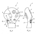
Figur 3- eine Draufsicht auf einen Multifunktionsgriff und
Figur 4- eine Seitenansicht des Multifunktionsgriffs.
- Figure 1
- a schematic side view of a forage harvester,
- Figure 2
- 2 shows a schematic representation of a device according to the invention, which is arranged in a driver's cab of the forage harvester according to FIG. 1 or a combine harvester,
- Figure 3
- a top view of a multi-function handle and
- Figure 4
- a side view of the multi-function handle.
Die erfindungsgemäße Vorrichtung findet Einsatz als Bedieneinheit in landwirtschaftlichen Fahrzeugen, wie beispielsweise Feldhäckslern und Mähdreschern.The device according to the invention is used as an operating unit in agricultural Vehicles such as forage harvesters and combine harvesters.
In Figur 1 ist ein Feldhäcksler 30 dargestellt. Der Feldhäcksler 30 weist einen mittels
Hydraulikzylinder 31 betätigbaren Überladekrümmer 32 auf. Ferner weist der Feldhäcksler
30 ein über ein Einzugsaggregat 33 mit der Chassis verbundenen Pick-up
34 auf, an dem eine Einzugsschnecke 35, Rollenniederhalter 36 sowie ein Stützrad
37 befestigt sind.A
Weiterhin weist der Feldhäcksler 30 eine Führerkabine 38 auf, in der ein Lenkrad 39
zum Lenken des Feldhäckslers 30 sowie eine Mehrzahl von Bedienelementen 40
zum Bedienen der vorgenannten Steuerfunktionen angeordnet sind. Die Bedienelemente
40, die auf elektrischem oder elektromechanischem Weg auch auf nicht dargestellte
Stelleinheiten des Feldhäckslers 30 einwirken, sind Bestandteil der erfindungsgemäßen
Vorrichtung. Die erfindungsgemäße Vorrichtung besteht im Wesentlichen
aus einem Multifunktionsgriff 1 sowie einem Auswahl/Übergabe-Bedienelement
12, die beide in der Führerkabine 38 angeordnet sind. Der Multifunktionsgriff
1 ist in einer solchen Höhe angeordnet, dass der Fahrzeuglenker diesen
mit der rechten Hand umfassen und die Bedienelemente desselben mit wenigen
Fingern betätigen kann. Das Auswahl/Übergabe-Bedienelement 12 kann im Fußbereich
als Fußschalter 22, am Lenkrad 39, an der linken Armlehne oder am Multifunktionsgriff
1 selbst angeordnet sein. Ferner kann die erfindungsgemäße Vorrichtung
eine als Monitor ausgebildeten elektronischen Anzeigeeinheit 2 sowie ein Bedienpult
3 umfassen.The
Die im Folgenden beschriebene erfindungsgemäße Vorrichtung dient zur Betätigung von Stellfunktionen eines Mähdreschers. In gleicher Art und Weise kann aber auch die Betätigung von entsprechenden, oben beschriebenen Stellfunktionen des Feldhäckslers 30 erfolgen. The device according to the invention described below is used for actuation of control functions of a combine harvester. In the same way you can the actuation of corresponding control functions of the forage harvester described above 30 done.
Der Multifunktionsgriff 1 weist eine Mehrzahl von Bedienelementen 4, 5, 6 auf.The multifunction handle 1 has a plurality of
Das Bedienelement 4 ist als Mehrfach-Bedienelement oder Zweifach-Bedienelement
ausgebildet. Das Mehrfach-Bedienelement ist ellipsenförmig ausgebildet und ermöglicht
durch Betätigung an gegenüberliegenden Endbereichen mit relativ kleinem Radius,
dass das Schneidwerk eines Mähdreschers entweder gehoben oder gesenkt
wird. Dies wird durch die als Pfeile ausgebildeten Funktionssymbole 9 kenntlich gemacht.The
In unmittelbarem funktionellem Zusammenhang zu dem Mehrfach-Bedienelement 4
ist das Ein-Aus-Bedienelement 5 zu sehen, mittels dessen das Schneidwerk ein-
bzw. ausgeschaltet werden kann. Zu diesem Zweck ist eine Ein-Taste 5' zum Einschalten
des Schneidwerkes und zum anderen eine Aus-Taste 5" zum Ausschalten
des Schneidwerkes vorgesehen.In a direct functional connection to the
Als weiteres Bedienelement 6 ist ein Haspelsteuerungs-Bedienelement vorgesehen, dass - wie das Schneidwerksteuerungs-Bedienelement 4 - als Mehrfach-Bedienelement ausgebildet ist. Beim Betätigen der in der Blattebene von Figur 2 nach oben und unten weisenden Bereiche des Bedienelementes 6 - kenntlich gemacht durch Pfeile 9 als Funktionssymbole - wird ein Heben und Senken der Haspel bewirkt: Beim Betätigen in Bereichen des Bedienelementes 6, in dem gemäß Figur 2 Pfeile als Funktionssymbole 9 in der Blattebene nach links und nach rechts orientiert sind, wird ein Vor- und Zurückbewegen der Haspel bewirkt.A reel control control element is provided as a further control element 6, that - like the cutter control control 4 - as a multiple control is trained. When pressing the in the sheet plane of Figure 2 areas of the control element 6 pointing upwards and downwards - identified by arrows 9 as function symbols - is a lifting and lowering of the reel causes: when actuated in areas of the control element 6, in the according to FIG Arrows oriented as function symbols 9 in the leaf plane to the left and to the right the reel is moved back and forth.
Die Bedienelemente 4, 5, 6 betreffen eine Kategorie von ersten Steuerfunktionen,
die beim Fahren des Mähdreschers relativ häufig und während der Fahrt betätigt
werden müssen.The
Die Mehrfach-Bedienelemente 4, 6 sind vorzugsweise als Wipp- oder Kippschalter
ausgebildet. Die Bedienelemente 4, 5, 6 sind in einem oberen Bereich eines Griffteils
11 des Multifunktionsgriffes 1 angeordnet. The
Wie aus Figur 2 zu ersehen ist, ist der Multifunktionsgriff 1 in einem Trägergehäuse
10 beweglich gelagert, so dass die Fahrtrichtung und/oder die Fahrgeschwindigkeit
des Mähdreschers durch Vorschieben und Zurückziehen des Multifunktionsgriffes 1
gesteuert werden kann.As can be seen from Figure 2, the multi-function handle 1 is in a
Weiterhin ist an dem Griffteil 11 ein weiteres Bedienelement 12 angeordnet, das als
Auswahl/Übergabe-Bedienelement ausgebildet ist. Das Auswahl/Übergabe-Bedienelement
12 weist mehrere Schaltstellungen (drei Schaltstellungen) auf, so
dass die Zuordnung des Mehrfach-Bedienelements 4 zu der einzigen ersten Steuerfunktion
(Grundfunktion), nämlich Schneidwerk heben/senken (SW), einerseits und
zu zwei weiteren zweiten Steuerfunktionen andererseits eingestellt werden kann. Die
zweiten Steuerfunktionen betreffen die Einstellung.von Stelleinheiten, die nicht häufig
vorkommen und üblicherweise mittels Bedienelemente 13 des Bedienpultes 3
vorgenommen werden.Furthermore, a
Wie aus Figur 3 und 4 zu ersehen ist, ist das Auswahl/Übergabe-Bedienelement 12
als Drehschalter ausgebildet, der bereichsweise durch eine schlitzförmige Ausnehmung
aus dem Griffteil 11 herausragt. Dieser Teilbereich 14 dient zum Erfassen und
Verdrehen des Auswahl/Übergabe-Bedienelements 12, wobei durch eine kreisförmige
Ausnehmung 15 an einer Oberseite 16 des Griffteils 11 die aktuelle Schaltstellung
des Auswahl/Übergabe-Bedienelements 12 signalisiert wird. Die Signalisierung
wird unterstützt durch eine Linse 41, die im Bereich der Ausnehmung 15 angeordnet
ist. Auf diese Weise kann das Funktionssymbol 17 vergrößert dargestellt werden.
Die gewünschte Steuerfunktion wird durch Betätigen des als Rändelrad ausgebildeten
Auswahl/Übergabe-Bedienelements 12 bewirkt, wobei in einer Raststellung, in
der das die Steuerfunktion symbolisierende Funktionssymbol 17 fluchtend zu der
Ausnehmung 15 angeordnet ist, die gewünschte Steuerfunktion eingestellt ist. Das
Rändelrad 12 weist im vorliegenden Ausführungsbeispiel 3 Funktionssymbole 17
auf, wobei lediglich ein einziges durch die Ausnehmung 15 sichtbar ist. Dieses
sichtbare Funktionssymbol 17 korrespondiert zu der gewünschten Steuerfunktion,
die mit einem anderen Bedienelement 4, das fest diesem Auswahl/Ubergabe-Bedienelement
12 zugeordnet ist, betätigt werden kann.As can be seen from FIGS. 3 and 4, the selection /
Im vorliegenden Ausführungsbeispiel ermöglicht die Einstellung des Auswahl/Übergabe-Bedienelements 12 die Einstellung von zwei weiteren Steuerfunktionen, nämlich zum einen das "Korntankrohr schwenken" sowie das "Querschwenken des Schneidwerks". Die erste Steuerfunktion "Schneidwerk heben/senken" wird durch das Funktionssymbol SW (17) signalisiert.In the present exemplary embodiment, the selection / transfer control element can be set 12 the setting of two further control functions, namely on the one hand the "swivel the grain tank pipe" and the "cross swivel of the cutting unit ". The first control function" lifting / lowering the cutting unit "is indicated by the function symbol SW (17).
Je nach Stellung des Auswahl/Übergabe-Bedienelements 12 lässt sich eine dieser
genannten Steuerfunktionen dem Mehrfach-Bedienelement 4 direkt zuordnen, so
dass in Abhängigkeit von der Schaltstellung des Auswahl/Übergabe-Bedienelements
12 die entsprechende Steuerfunktion durch das Mehrfach-Bedienelement 4 eingestellt
werden kann. Im vorliegenden Ausführungsbeispiel ist die erste Steuerfunktion
"Schneidwerk heben/senken" SW eingestellt.Depending on the position of the selection /
Das Rändelrad 12 ist haptisch wahrnehmbar ausgebildet und weist an der
Umfangsfläche eine geriffelte Oberflächenstruktur 21 auf. Die Betätigung des
Rändelrads 12 erfolgt rastend, wobei drei zu den Steuerfunktionen
korrespondierende Rastpositionen einnehmbar sind.The
Nach einer speziellen Ausführungsform des Auswahl/Übergabe-Bedienelements 12
können die Schaltpositionen unterschiedlich haptisch wahrnehmbar sein, wobei beispielsweise
die Formgebung des herausragenden Teilbereiches 14 in einer Schaltstellung
konkavförmig und in einer anderen Schaltstellung konvexförmig ausgestaltet
sein kann.According to a special embodiment of the selection /
Nach einer alternativen Ausführungsform des Auswahl/Übergabe-Bedienelements
12 kann dieses auch mit einem Anschlag versehen sein, so dass die Bedienperson
stets durch Zurückdrehen des Bedienelementes 12 bis zum Anschlag in die Grundstellung
bringbar ist, in der die erste Steuerfunktion durch das Bedienelement 4 einstellbar
ist. According to an alternative embodiment of the selection /
In Figur 3 sind die Funktionssymbole 17 der Steuerfunktionen, die mittels des Bedienelementes
12 einstellbar sind, auf der Oberseite 16 des Griffteils 11 in der entsprechenden
Reihenfolge der Schaltstellungen dargestellt. Hierdurch wird dem Fahrer
signalisiert, welche Steuerfunktionen mittels des Rändelrades 12 einstellbar sind.
Die aktuell eingestellte Steuerfunktion ergibt sich aus dem durch die Linse 41 und
die Ausnehmung 15 erkennbaren Funktionssymbol 17. Zur weiteren Hervorhebung
der aktuell eingestellten Steuerfunktion kann das Funktionssymbol 17, das in der
Ausnehmung 15 sichtbar ist, beleuchtet ausgebildet sein.In Figure 3, the
Nach einer alternativen Ausführungsform des Auswahl/Übergabe-Bedienelements
12 kann dieses als Schiebeschalter 42 ausgebildet sein, der linear in verschiedene
Schältpositionen bewegbar ist. Der Schiebeschalter 42 kann beispielsweise zwei
Stellungen aufweisen, wobei in der ersten Schaltstellung ein Automatikbetrieb und in
einer zweiten Schaltstellung ein manueller Betrieb der mittels der Bedienelemente 5
und 6 betätigbaren Schaltfunktionen eingestellt wird. Seitlich neben dem Schiebeschalter
können die entsprechenden Funktionssymbole in einer Reihe angeordnet
sein, wobei die Steuerfunktion durch Verstellung des Schiebeschalters korrespondierend
zu dem entsprechenden Funktionssymbol erfolgt.According to an alternative embodiment of the selection /
Nach einer Ausführungsform der Erfindung können die Funktionssymbole alternativ
oder zusätzlich in der elektronischen Anzeigeeinheit 2 dargestellt werden. Auf diese
Weise wird eine einfache Zuordnung von Steuerfunktionen zu dem Bedienelement 4
auf dem Multifunktionsgriff 1 vorgenommen, wobei. die Bedienperson lediglich den
Blick auf den ergonomisch angeordneten Monitor 2 richten muss. Für diesen
Einsatzzweck reicht es aus, dass das Auswahl/Übergabe-Bedienelement 12 haptisch
wahrnehmbar ist, um eine einfache Erfassbarkeit desselben zu ermöglichen.
Durch Betätigen des Auswahl/Übergabe-Bedienelements 12 kann dann die gewünschte
Einstellung bzw. Zuordnung der Steuerfunktion vorgenommen werden.According to one embodiment of the invention, the function symbols can alternatively
or can also be shown in the
Vorteilhaft ermöglicht die erfindungsgemäße Vorrichtung, dass ein Großteil der
Steuerfunktionen, die ansonsten durch ortsfern angeordnete Bedienelemente 13
betätigbar sind, auf den Multifunktionsgriff 1 übertragen werden. Dabei ist die zweite
Steuerfunktion unmittelbar und direkt einer Schaltstellung des Auswahl/Übergabe-Bedienelements
12 zugeordnet.The device according to the invention advantageously enables a large part of the
Control functions that are otherwise arranged by
Nach einer alternativen Ausführungsform gemäß Figur 4 ist ein Auswahl/Übergabe-Bedienelement
43 an einer Rückseite des Griffteils 11 angeordnet. Das Auswahl/Übergabe-Bedienelement
43 ist als Schiebeelement ausgebildet und dient dazu,
den Bedienelementen 4, 5 und/oder 6 vorgegebene Steuerfunktionen zuzuordnen.
In einer ersten Stellung des Bedienelementes 43 könnte mittels Betätigen der
Taste 5' eine Stillsetzung und Reversierung des Einzugsaggregates 33 erfolgen. In
der zweiten Stellung des Bedienelementes 43 kann bei Betätigen der Taste 5'
gleichzeitig mit der Reversierung eine Verschwenkung des Rollenniederhalters 36
erfolgen. Vorteilhaft kann der Fahrer individuell vor jedem Reversieren durch Betätigen
des Auswahl/Übergabe-Bedienelementes 43 voreinstellen, welcher funktionaler
Zusammenhang erwünscht ist, ohne dass dafür die Hand von dem Multifunktionsgriff
1 entfernt werden müsste.According to an alternative embodiment according to FIG. 4 is a selection /
Vorteilhaft sind die entsprechenden Bedienelemente 4, 5, 6 in einer gemeinsamen
Ebene am Griffteil 11 angeordnet, so dass diese auf einfache Weise mittels eines
Fingers erreichbar sind.The corresponding
Die Verwendung der Auswahl/Übergabe-Bedienelemente 12, 43 ist für seltene Betätigungen
von Stellfunktionen der Erntemaschine vorgesehen, beispielsweise Korntankrohr
schwenken, Schneidwerktischlänge einstellen, manuelle Querneigung-Schneidwerk
einstellen oder Schnittwinkel-Schneidwerk einstellen. Alternativ ist es
auch möglich, mit einem Auswahl/Übergabe-Bedienelement 12, 43 direkt Einstellwerte
der Erntemaschine, die ebenfalls nur von Zeit zu Zeit im Arbeitsbetrieb eingestellt
werden müssen, den Bedienelementen 5, 6 oder zuzuordnen.The use of the selection / transfer controls 12, 43 is for rare operations
provided by control functions of the harvesting machine, for example grain tank pipe
swivel, adjust cutting table length, manual cross-cutting device
adjust or set cutting angle cutting unit. Alternatively it is
also possible with a selection /
Die Auswahl/Übergabe-Bedienelemente 12, 43 können zum einen unmittelbar am
Griffteil 11 angeordnet sein. Alternativ können diese auch in einem Betätigungsumfeld
des Fahrzeugführers innerhalb der Kabine 38 angeordnet sein, wie beispielsweise
im Fußbereich. Vorteilhaft können mehrere Auswahl/Übergabe-Bedienelemente
12, 43 vorgesehen sein, die jeweils bestimmten und festgelegten
Bedienelementen 4, 5, 6, zugeordnet sind. Auf diese Weise wird sichergestellt, dass
der Fahrzeugführer die durch die Auswahl/Übergabe-Bedienelemente 12, 43 vorauswählbaren
Steuerfunktionen den betreffenden Bedienelementen 4, 5, 6, zuordnen
kann. Dies wird vorteilhafter Weise dadurch bewirkt, dass sich die Auswahl/Übergabe-Bedienelemente
12, 43 in örtlicher Nähe zu den korrespondierenden
Bedienelementen 4, 5, 6, befinden. Diese funktionelle Verknüpfung kann zusätzlich
durch Markierungen, beispielsweise Verbindungslinien, auf dem Griffteil 11 unterstützt
werden.The selection / transfer controls 12, 43 can on the one hand directly on
Claims (11)
dadurch gekennzeichnet, dass
mindestens ein Bedienelement (4,5,6) des Multifunktionsgriffs (1) als Mehrfach-Bedienelement ausgebildet ist, dass in einem Betätigungsumfeld des Fahrzeugführers wenigstens ein Auswahl/Übergabe-Bedienelement (12) angeordnet ist, derart, dass durch Betätigung des Auswahl/Übergabe-Bedienelements (12) unmittelbar wenigstens eine Einstellung zumindest einer weiteren Steuerfunktion des Fahrzeugs (30) dem Mehrfach- Bedienelement zugeordnet und durch dessen Betätigung erfolgen kann.Device for controlling an agricultural vehicle, in particular a combine harvester, which is arranged in the driver's cab in the area of action of the vehicle driver, with a multi-function handle, which has a handle part with a plurality of operating elements, the operating elements being arranged such that they are operated with one or two fingers a hand of the vehicle driver resting on the grip part can be safely reached that the control elements serve to set the first control functions of the vehicle,
characterized in that
at least one control element (4, 5, 6) of the multi-function handle (1) is designed as a multiple control element that at least one selection / transfer control element (12) is arranged in an operating environment of the vehicle driver, such that by actuating the selection / transfer Control element (12) directly assigns at least one setting of at least one further control function of the vehicle (30) to the multiple control element and can be carried out by actuating it.
dadurch gekennzeichnet, dass
mindestens ein Bedienelement des Multifunktionsgriffs (1) als Mehrfach-Bedienelement (4) ausgebildet ist, dass an dem Multifunktionsgriff (1) ein Auswahl/Übergabe-Bedienelement (12) angeordnet ist, derart, dass durch Betätigung des Auswahl/Übergabe-Bedienelements (12) unmittelbar die Einstellbarkeit mindestens einer eigentlich durch das Bedienelement (13) des Bedienpults (3) einstellbaren vorgegebenen zweiten Steuerfunktion von demselben Bedienelement (13) auf das Mehrfach-Bedienelement (4) übertragen wird, so dass die Einstellbarkeit der vorgegebenen zweiten Steuerfunktion durch die Betätigung des Mehrfach-Bedienelementes (4) erfolgen kann, und dass die Zuordnung der zweiten Steuerfunktion durch Funktionssymbole (9) visualisiert ist. Device according to claim 1,
characterized in that
at least one control element of the multi-function handle (1) is designed as a multiple control element (4) such that a selection / transfer control element (12) is arranged on the multi-function handle (1) such that by actuating the selection / transfer control element (12 ) the adjustability of at least one predetermined second control function that is actually adjustable by the control element (13) of the control panel (3) is transferred from the same control element (13) to the multiple control element (4), so that the adjustability of the predetermined second control function by actuation of the multiple control element (4), and that the assignment of the second control function is visualized by function symbols (9).
dadurch gekennzeichnet, dass
das Mehrfach-Bedienelement (4) mindestens zwei Schaltstellungen aufweist, wobei dem Mehrfach-Bedienelement (4) in der ersten Schaltstellung die einzige erste Steuerfunktion und in der zweiten Schaltstellung die vorgegebene zweite Steuerfunktion zugeordnet ist.Device according to claim 1 or 2,
characterized in that
the multiple control element (4) has at least two switching positions, the multiple control element (4) being assigned the only first control function in the first switching position and the predetermined second control function in the second switching position.
dadurch gekennzeichnet, dass
das Auswahl/Übergabe-Bedienelement (12) als Mehrfachschalter ausgebildet ist, wobei in Abhängigkeit von der Schaltstellung desselben die entsprechend eingestellte Steuerfunktion optisch hervorgehoben im Bereich des Mehrfachschalters angezeigt wird.Device according to one of claims 1 to 3,
characterized in that
the selection / transfer control element (12) is designed as a multiple switch, the correspondingly set control function being displayed in the area of the multiple switch, depending on the switch position thereof, in an optically highlighted manner.
dadurch gekennzeichnet, dass
der Mehrfachschalter (12) als mehrstufiger Dreh- oder Schiebeschalter ausgebildet ist, wobei den Schaltstellungen des Schalters jeweils unmittelbar am Schalter angeordnete Funktionssymbole (9) zugeordnet sind.Device according to claim 4,
characterized in that
the multiple switch (12) is designed as a multi-stage rotary or slide switch, with the switching positions of the switch being assigned function symbols (9) which are arranged directly on the switch.
dadurch gekennzeichnet, dass
das Mehrfach-Bedienelement (4) als ein Kipp- oder Wippschalter ausgebildet ist.Device according to one of claims 1 to 5,
characterized in that
the multiple control element (4) is designed as a toggle or rocker switch.
dadurch gekennzeichnet, dass
der Drehschalter (13) als Rändelrad ausgebildet ist, das bereichsweise durch eine Ausnehmung des Griffteils (11) herausragt und den Steuerfunktionen zugeordnete Rastpositionen aufweist. Apparatus according to claim 5 or 6,
characterized in that
the rotary switch (13) is designed as a knurled wheel, which in some areas protrudes through a recess in the handle part (11) and has detent positions assigned to the control functions.
dadurch gekennzeichnet, dass
die Rastpositionen haptisch wahrnehmbar sind.Device according to claim 7,
characterized in that
the locking positions can be perceived haptically.
dadurch gekennzeichnet, dass
die Rastpositionen unterschiedlich haptisch wahrnehmbar sind.Apparatus according to claim 7 or 8,
characterized in that
the rest positions can be perceived differently by haptic.
dadurch gekennzeichnet, dass
das Auswahl/Übergabe-Bedienelement (12) in einer Schaltstellung, in der das Mehrfach-Bedienelement (4) die erste Steuerfunktion zugeordnet ist; an einem Anschlag anliegt.Device according to one of claims 1 to 9,
characterized in that
the selection / transfer control element (12) in a switch position in which the multiple control element (4) is assigned the first control function; abuts a stop.
dadurch gekennzeichnet, dass
das der aktuellen Schaltstellung des Auswahl/Übergabe-Bedienelementes (12) zugeordnete Funktionssymbol (9) beleuchtet ausgebildet ist.Device according to one of claims 1 to 10,
characterized in that
the function symbol (9) assigned to the current switching position of the selection / transfer control element (12) is illuminated.
Applications Claiming Priority (2)
| Application Number | Priority Date | Filing Date | Title |
|---|---|---|---|
| DE10140975 | 2001-08-27 | ||
| DE10140975A DE10140975A1 (en) | 2001-08-27 | 2001-08-27 | Device for controlling an agricultural vehicle |
Publications (3)
| Publication Number | Publication Date |
|---|---|
| EP1288763A2 true EP1288763A2 (en) | 2003-03-05 |
| EP1288763A3 EP1288763A3 (en) | 2004-02-25 |
| EP1288763B1 EP1288763B1 (en) | 2009-03-11 |
Family
ID=7696140
Family Applications (1)
| Application Number | Title | Priority Date | Filing Date |
|---|---|---|---|
| EP02018503A Expired - Lifetime EP1288763B1 (en) | 2001-08-27 | 2002-08-16 | Apparatus for controlling an agricultural vehicle |
Country Status (4)
| Country | Link |
|---|---|
| US (1) | US6932183B2 (en) |
| EP (1) | EP1288763B1 (en) |
| AT (1) | ATE425482T1 (en) |
| DE (2) | DE10140975A1 (en) |
Cited By (9)
| Publication number | Priority date | Publication date | Assignee | Title |
|---|---|---|---|---|
| EP1714847A2 (en) | 2005-04-20 | 2006-10-25 | Cnh U.K. Limited | Agricultural vehicle with reconfigurable control |
| EP1900974A1 (en) * | 2006-09-14 | 2008-03-19 | Fico Triad S.A. | Transmission control lever with user interface |
| WO2008066648A2 (en) * | 2006-11-30 | 2008-06-05 | Caterpillar Inc. | Repositioning assist for an excavating operation |
| EP1953618A1 (en) * | 2007-02-02 | 2008-08-06 | Deere & Company | Operating device for a vehicle |
| EP1980443A1 (en) * | 2007-04-11 | 2008-10-15 | Deere & Company | Operating device of a vehicle |
| DE102009036318A1 (en) | 2009-02-09 | 2010-08-12 | Elobau Gmbh & Co. Kg | Electric switch e.g. Hall-switch, for use on operating elements of e.g. harvester, has control unit directly actuated by solid body outside of switch and illuminated in different colors based on positions using LED |
| EP3115863A3 (en) * | 2015-07-03 | 2017-01-25 | MULAG FAHRZEUGWERK Heinz Wössner GmbH & CO. KG | Control element |
| EP3132964A3 (en) * | 2014-07-08 | 2017-03-29 | Kubota Corporation | Multifunction operation tool, armrest operation device and work vehicle |
| DE102017127560A1 (en) | 2017-11-22 | 2019-05-23 | Claas Selbstfahrende Erntemaschinen Gmbh | Operating system for an agricultural working machine |
Families Citing this family (31)
| Publication number | Priority date | Publication date | Assignee | Title |
|---|---|---|---|---|
| US20060016634A1 (en) * | 2004-07-22 | 2006-01-26 | Cnh America Llc | Handle-style loading control panel for bale wagons |
| US7188698B1 (en) * | 2004-08-23 | 2007-03-13 | Glazer Enterprises, Inc. | Control knob throttle modulation |
| US7334658B2 (en) * | 2004-12-23 | 2008-02-26 | Caterpillar Inc. | Steering system with joystick mounted controls |
| US7516811B2 (en) * | 2005-02-22 | 2009-04-14 | Gm Global Technology Operations, Inc. | Vehicle accessory pedal and method |
| DE102005013373B4 (en) * | 2005-03-23 | 2007-10-04 | Daimlerchrysler Ag | Multifunction control handle for vehicles |
| US7275616B2 (en) * | 2005-06-30 | 2007-10-02 | Cnh America Llc | Adjustable combination propulsion and control handle for a work machine |
| DE102005056554A1 (en) * | 2005-11-25 | 2007-06-14 | Usines Claas France S.A.S., St. Rémy-Woippy | Collecting device for agricultural harvesters |
| JP4091955B2 (en) * | 2005-12-02 | 2008-05-28 | 新キャタピラー三菱株式会社 | Work machine |
| DE102006018537B4 (en) * | 2006-04-21 | 2013-11-07 | Grammer Aktiengesellschaft | Control console on an armrest of a vehicle seat |
| ITTO20070569A1 (en) * | 2007-07-31 | 2009-02-01 | Monchiero & C S N C | MACHINE OPERATOR WITH A JOYSTICK CONTROL AND CONTROL SYSTEM |
| US8108098B2 (en) * | 2007-09-12 | 2012-01-31 | International Business Machines Corporation | Control appropriateness illumination for corrective response |
| DE102008018877A1 (en) | 2008-04-14 | 2009-10-15 | Claas Selbstfahrende Erntemaschinen Gmbh | Agricultural machine with emergency stop function |
| DE102008057461A1 (en) * | 2008-11-14 | 2010-05-20 | Claas Selbstfahrende Erntemaschinen Gmbh | display unit |
| US8186136B2 (en) * | 2009-04-03 | 2012-05-29 | Deere & Company | Agricultural harvester with a draper platform direction shuttle |
| DE102009034154A1 (en) * | 2009-07-20 | 2011-02-03 | Claas Selbstfahrende Erntemaschinen Gmbh | Multi-function handle |
| GB0916234D0 (en) * | 2009-09-16 | 2009-10-28 | Agco Gmbh | Control unit for display terminal |
| US8100218B2 (en) * | 2009-10-19 | 2012-01-24 | Cnh America Llc | Electronic throttle on control handle |
| US8272468B2 (en) * | 2010-02-25 | 2012-09-25 | Yanmar Co., Ltd. | Work machine |
| EP2707546B1 (en) * | 2011-05-12 | 2017-03-08 | Bombardier Inc. | Joystick for an aircraft |
| CA2839316C (en) | 2011-12-29 | 2019-04-30 | Clark Equipment Company | Electronic tag along |
| DE102012002992A1 (en) * | 2012-02-15 | 2013-08-22 | Claas Selbstfahrende Erntemaschinen Gmbh | Agricultural work vehicle |
| CN104756034B (en) * | 2012-10-22 | 2017-06-23 | 派克·汉尼汾制造瑞典公司 | Control stick |
| US9908614B2 (en) * | 2014-05-02 | 2018-03-06 | Sikorsky Aircraft Corporation | Crew seat integral inceptor system for aircraft |
| USD753118S1 (en) * | 2014-11-24 | 2016-04-05 | Caterpillar Inc. | Controller |
| DE102014117544A1 (en) * | 2014-11-28 | 2016-06-02 | Claas Saulgau Gmbh | Human machine interface for an agricultural implement, control system and agricultural implement |
| JP1543259S (en) * | 2015-07-31 | 2016-02-08 | ||
| JP1543258S (en) * | 2015-07-31 | 2016-02-08 | ||
| US20170112061A1 (en) * | 2015-10-27 | 2017-04-27 | Cnh Industrial America Llc | Graphical yield monitor static (previous) data display on in-cab display |
| US10640950B2 (en) * | 2016-02-19 | 2020-05-05 | Komatsu Ltd. | Operation device of work vehicle |
| DE102016203763A1 (en) | 2016-03-08 | 2017-09-14 | Deere & Company | Method and arrangement for controlling driving conditions of a commercial vehicle |
| US11866909B2 (en) * | 2020-11-04 | 2024-01-09 | Caterpillar Inc. | Machine control component with input device to control machine display |
Citations (1)
| Publication number | Priority date | Publication date | Assignee | Title |
|---|---|---|---|---|
| DE19619419A1 (en) | 1996-05-14 | 1997-11-20 | Claas Ohg | Control device |
Family Cites Families (15)
| Publication number | Priority date | Publication date | Assignee | Title |
|---|---|---|---|---|
| SE431433B (en) * | 1982-06-01 | 1984-02-06 | Saab Scania Ab | MULTIPLE FUNCTIONS |
| DE3901649C2 (en) * | 1989-01-20 | 1995-04-06 | Kloeckner Humboldt Deutz Ag | Device for controlling an agricultural vehicle |
| DE9110099U1 (en) * | 1990-09-28 | 1991-11-14 | Kuepper-Weisser Gmbh, 7715 Braeunlingen, De | |
| US5161422A (en) * | 1991-07-12 | 1992-11-10 | Prince Corporation | Universal control for electrically controlled vehicle transmission |
| DE4204223A1 (en) * | 1992-02-13 | 1993-08-19 | Zahnradfabrik Friedrichshafen | CONTROL STICK FOR SWITCHING OR OPERATING COMPONENTS OF A COMMERCIAL VEHICLE |
| DE4433573A1 (en) * | 1994-09-07 | 1996-03-14 | Fendt Xaver Gmbh & Co | Multi-junction control lever |
| FR2727821A1 (en) * | 1994-12-13 | 1996-06-14 | Lucas Sa G | CONTROL SYSTEM OF A MACHINE EQUIPPED WITH SEVERAL HYDRAULIC MOTORS, ATTACHED TO AN AGRICULTURAL TRACTOR |
| DE29516666U1 (en) * | 1995-10-21 | 1995-12-21 | Kuepper Weisser Gmbh | Control unit with control panel and electronic display unit for controlling work equipment on commercial vehicles |
| DE19548717C1 (en) * | 1995-12-23 | 1997-05-07 | Daimler Benz Ag | Control element arrangement for controlling the longitudinal movement and / or the transverse movement of a motor vehicle |
| DE19624463A1 (en) * | 1996-06-19 | 1998-01-02 | Fendt Xaver Gmbh & Co | Control device for commercial vehicles, in particular for agricultural tractors |
| US5939796A (en) * | 1998-01-23 | 1999-08-17 | Ut Automotive Dearborn, Inc. | Combination mirror and memory switch |
| CA2256172A1 (en) * | 1998-12-15 | 2000-06-15 | Bombardier Inc. | Multifunction joystick |
| US6425729B1 (en) * | 2000-03-24 | 2002-07-30 | Caterpillar Inc. | Arrangement for controlling a work machine |
| US6550562B2 (en) * | 2000-12-08 | 2003-04-22 | Clark Equipment Company | Hand grip with microprocessor for controlling a power machine |
| JP2002347538A (en) * | 2001-03-19 | 2002-12-04 | Alps Electric Co Ltd | Control device for on-vehicle apparatus |
-
2001
- 2001-08-27 DE DE10140975A patent/DE10140975A1/en not_active Withdrawn
-
2002
- 2002-08-16 EP EP02018503A patent/EP1288763B1/en not_active Expired - Lifetime
- 2002-08-16 DE DE50213343T patent/DE50213343D1/en not_active Expired - Lifetime
- 2002-08-16 AT AT02018503T patent/ATE425482T1/en not_active IP Right Cessation
- 2002-08-27 US US10/229,241 patent/US6932183B2/en not_active Expired - Fee Related
Patent Citations (1)
| Publication number | Priority date | Publication date | Assignee | Title |
|---|---|---|---|---|
| DE19619419A1 (en) | 1996-05-14 | 1997-11-20 | Claas Ohg | Control device |
Cited By (18)
| Publication number | Priority date | Publication date | Assignee | Title |
|---|---|---|---|---|
| EP1714847A3 (en) * | 2005-04-20 | 2007-05-02 | Cnh U.K. Limited | Agricultural vehicle with reconfigurable control |
| EP1714847A2 (en) | 2005-04-20 | 2006-10-25 | Cnh U.K. Limited | Agricultural vehicle with reconfigurable control |
| EP1714847B2 (en) † | 2005-04-20 | 2013-12-18 | Cnh U.K. Limited | Agricultural vehicle with reconfigurable control |
| EP1900974A1 (en) * | 2006-09-14 | 2008-03-19 | Fico Triad S.A. | Transmission control lever with user interface |
| US7634863B2 (en) | 2006-11-30 | 2009-12-22 | Caterpillar Inc. | Repositioning assist for an excavating operation |
| WO2008066648A2 (en) * | 2006-11-30 | 2008-06-05 | Caterpillar Inc. | Repositioning assist for an excavating operation |
| WO2008066648A3 (en) * | 2006-11-30 | 2008-08-14 | Caterpillar Inc | Repositioning assist for an excavating operation |
| EP1953618A1 (en) * | 2007-02-02 | 2008-08-06 | Deere & Company | Operating device for a vehicle |
| US7823685B2 (en) | 2007-02-02 | 2010-11-02 | Deere & Company | Operating device for a vehicle |
| EP1980443A1 (en) * | 2007-04-11 | 2008-10-15 | Deere & Company | Operating device of a vehicle |
| DE102009036318A1 (en) | 2009-02-09 | 2010-08-12 | Elobau Gmbh & Co. Kg | Electric switch e.g. Hall-switch, for use on operating elements of e.g. harvester, has control unit directly actuated by solid body outside of switch and illuminated in different colors based on positions using LED |
| EP2282250A1 (en) | 2009-08-06 | 2011-02-09 | elobau GmbH & Co. KG | Thumbwheel |
| US8367956B2 (en) | 2009-08-06 | 2013-02-05 | Elobau Gmbh & Co. Kg | Thumbwheel |
| EP3132964A3 (en) * | 2014-07-08 | 2017-03-29 | Kubota Corporation | Multifunction operation tool, armrest operation device and work vehicle |
| EP3115863A3 (en) * | 2015-07-03 | 2017-01-25 | MULAG FAHRZEUGWERK Heinz Wössner GmbH & CO. KG | Control element |
| DE102017127560A1 (en) | 2017-11-22 | 2019-05-23 | Claas Selbstfahrende Erntemaschinen Gmbh | Operating system for an agricultural working machine |
| US10926636B2 (en) | 2017-11-22 | 2021-02-23 | Claas Selbstfahrende Erntemaschinen Gmbh | Control system for an agricultural working vehicle |
| RU2771060C2 (en) * | 2017-11-22 | 2022-04-25 | КЛААС Зельбстфаренде Эрнтемашинен ГмбХ | Control system for agricultural working machine |
Also Published As
| Publication number | Publication date |
|---|---|
| EP1288763B1 (en) | 2009-03-11 |
| ATE425482T1 (en) | 2009-03-15 |
| US20030037985A1 (en) | 2003-02-27 |
| DE50213343D1 (en) | 2009-04-23 |
| US6932183B2 (en) | 2005-08-23 |
| DE10140975A1 (en) | 2003-03-20 |
| EP1288763A3 (en) | 2004-02-25 |
Similar Documents
| Publication | Publication Date | Title |
|---|---|---|
| EP1288763B1 (en) | Apparatus for controlling an agricultural vehicle | |
| DE60309409T2 (en) | System for programming a robot or similar machine with a portable programming terminal | |
| EP0635388B1 (en) | Motor vehicle with control device mounted on the steering wheel | |
| DE19619419B4 (en) | control unit | |
| EP1693334B1 (en) | Hand operated control device for the operator's compartment of a industrial vehicle | |
| EP2670615B1 (en) | Device for controlling multiple different functions of a motor vehicle | |
| EP0947906B1 (en) | Manually actuated control device for an operator stand or seat | |
| DE2343297A1 (en) | MULTIPLE CONTROL DEVICE | |
| DE4132499A1 (en) | Actuator system, e.g. for window, seat adjustment or sunroof of motor vehicle - combines command inputs with indicators giving open, closed and intermediate states | |
| DE4215097C2 (en) | Switch arrangement | |
| EP0608771A1 (en) | Device and method to actuate built-in components in motor véhicles | |
| DE102006007008A1 (en) | Motor vehicle comprises a driver assistance system comprises an operating section provided on the selecting lever with operating elements for operating the system | |
| DE19622493C5 (en) | Switching device for motor vehicles | |
| DE19824515C2 (en) | Switching element for actuating an openable vehicle roof | |
| DE3039584A1 (en) | REGULATING LEVER WITH ADDITIONAL SWITCHING DEVICES | |
| DE19926521B4 (en) | Operating arrangement for the electrical actuation of a motor-operated sliding roof in motor vehicles | |
| EP1659020A1 (en) | Seat adjusting switch with at least one rotatable operating element | |
| DE19757231B4 (en) | Multi-function switching device for motor vehicles | |
| DE60011786T2 (en) | Actuating device for working vehicles | |
| EP1188600A2 (en) | Control unit for multi media components in a motor vehicle | |
| DE10229160A1 (en) | Control system for a roof structure of a vehicle, roof structure and method for controlling a roof structure | |
| DE10334218A1 (en) | Multi position electrical switch for internal lighting in an automobile, has actuator that slides in four directions. | |
| EP1410939A1 (en) | Multiple switch | |
| DE2747589A1 (en) | DEVICE FOR DISPLAYING SYMBOLS ON GEAR LEVER | |
| EP1710114A1 (en) | Agricultural electronic monitoring and control device |
Legal Events
| Date | Code | Title | Description |
|---|---|---|---|
| PUAI | Public reference made under article 153(3) epc to a published international application that has entered the european phase |
Free format text: ORIGINAL CODE: 0009012 |
|
| AK | Designated contracting states |
Kind code of ref document: A2 Designated state(s): AT BE BG CH CY CZ DE DK EE ES FI FR GB GR IE IT LI LU MC NL PT SE SK TR Designated state(s): AT BE BG CH CY CZ DE DK EE ES FI FR GB GR IE IT LI LU MC NL PT SE SK TR |
|
| AX | Request for extension of the european patent |
Extension state: AL LT LV MK RO SI |
|
| PUAL | Search report despatched |
Free format text: ORIGINAL CODE: 0009013 |
|
| AK | Designated contracting states |
Kind code of ref document: A3 Designated state(s): AT BE BG CH CY CZ DE DK EE ES FI FR GB GR IE IT LI LU MC NL PT SE SK TR |
|
| AX | Request for extension of the european patent |
Extension state: AL LT LV MK RO SI |
|
| RIC1 | Information provided on ipc code assigned before grant |
Ipc: 7G 05G 9/047 A Ipc: 7E 02F 9/20 B |
|
| 17P | Request for examination filed |
Effective date: 20040825 |
|
| AKX | Designation fees paid |
Designated state(s): AT BE BG CH CY CZ DE DK EE ES FI FR GB GR IE IT LI LU MC NL PT SE SK TR |
|
| 17Q | First examination report despatched |
Effective date: 20060203 |
|
| GRAP | Despatch of communication of intention to grant a patent |
Free format text: ORIGINAL CODE: EPIDOSNIGR1 |
|
| GRAS | Grant fee paid |
Free format text: ORIGINAL CODE: EPIDOSNIGR3 |
|
| GRAA | (expected) grant |
Free format text: ORIGINAL CODE: 0009210 |
|
| AK | Designated contracting states |
Kind code of ref document: B1 Designated state(s): AT BE BG CH CY CZ DE DK EE ES FI FR GB GR IE IT LI LU MC NL PT SE SK TR |
|
| REG | Reference to a national code |
Ref country code: GB Ref legal event code: FG4D Free format text: NOT ENGLISH |
|
| REG | Reference to a national code |
Ref country code: CH Ref legal event code: EP |
|
| REG | Reference to a national code |
Ref country code: IE Ref legal event code: FG4D Free format text: LANGUAGE OF EP DOCUMENT: GERMAN |
|
| REF | Corresponds to: |
Ref document number: 50213343 Country of ref document: DE Date of ref document: 20090423 Kind code of ref document: P |
|
| PG25 | Lapsed in a contracting state [announced via postgrant information from national office to epo] |
Ref country code: FI Free format text: LAPSE BECAUSE OF FAILURE TO SUBMIT A TRANSLATION OF THE DESCRIPTION OR TO PAY THE FEE WITHIN THE PRESCRIBED TIME-LIMIT Effective date: 20090311 Ref country code: NL Free format text: LAPSE BECAUSE OF FAILURE TO SUBMIT A TRANSLATION OF THE DESCRIPTION OR TO PAY THE FEE WITHIN THE PRESCRIBED TIME-LIMIT Effective date: 20090311 |
|
| NLV1 | Nl: lapsed or annulled due to failure to fulfill the requirements of art. 29p and 29m of the patents act | ||
| PG25 | Lapsed in a contracting state [announced via postgrant information from national office to epo] |
Ref country code: SE Free format text: LAPSE BECAUSE OF FAILURE TO SUBMIT A TRANSLATION OF THE DESCRIPTION OR TO PAY THE FEE WITHIN THE PRESCRIBED TIME-LIMIT Effective date: 20090611 |
|
| REG | Reference to a national code |
Ref country code: IE Ref legal event code: FD4D |
|
| PG25 | Lapsed in a contracting state [announced via postgrant information from national office to epo] |
Ref country code: PT Free format text: LAPSE BECAUSE OF FAILURE TO SUBMIT A TRANSLATION OF THE DESCRIPTION OR TO PAY THE FEE WITHIN THE PRESCRIBED TIME-LIMIT Effective date: 20090824 Ref country code: ES Free format text: LAPSE BECAUSE OF FAILURE TO SUBMIT A TRANSLATION OF THE DESCRIPTION OR TO PAY THE FEE WITHIN THE PRESCRIBED TIME-LIMIT Effective date: 20090622 Ref country code: EE Free format text: LAPSE BECAUSE OF FAILURE TO SUBMIT A TRANSLATION OF THE DESCRIPTION OR TO PAY THE FEE WITHIN THE PRESCRIBED TIME-LIMIT Effective date: 20090311 Ref country code: CZ Free format text: LAPSE BECAUSE OF FAILURE TO SUBMIT A TRANSLATION OF THE DESCRIPTION OR TO PAY THE FEE WITHIN THE PRESCRIBED TIME-LIMIT Effective date: 20090311 Ref country code: IE Free format text: LAPSE BECAUSE OF FAILURE TO SUBMIT A TRANSLATION OF THE DESCRIPTION OR TO PAY THE FEE WITHIN THE PRESCRIBED TIME-LIMIT Effective date: 20090311 |
|
| PG25 | Lapsed in a contracting state [announced via postgrant information from national office to epo] |
Ref country code: SK Free format text: LAPSE BECAUSE OF FAILURE TO SUBMIT A TRANSLATION OF THE DESCRIPTION OR TO PAY THE FEE WITHIN THE PRESCRIBED TIME-LIMIT Effective date: 20090311 |
|
| PLBE | No opposition filed within time limit |
Free format text: ORIGINAL CODE: 0009261 |
|
| STAA | Information on the status of an ep patent application or granted ep patent |
Free format text: STATUS: NO OPPOSITION FILED WITHIN TIME LIMIT |
|
| PG25 | Lapsed in a contracting state [announced via postgrant information from national office to epo] |
Ref country code: DK Free format text: LAPSE BECAUSE OF FAILURE TO SUBMIT A TRANSLATION OF THE DESCRIPTION OR TO PAY THE FEE WITHIN THE PRESCRIBED TIME-LIMIT Effective date: 20090311 Ref country code: BG Free format text: LAPSE BECAUSE OF FAILURE TO SUBMIT A TRANSLATION OF THE DESCRIPTION OR TO PAY THE FEE WITHIN THE PRESCRIBED TIME-LIMIT Effective date: 20090611 |
|
| 26N | No opposition filed |
Effective date: 20091214 |
|
| PG25 | Lapsed in a contracting state [announced via postgrant information from national office to epo] |
Ref country code: MC Free format text: LAPSE BECAUSE OF NON-PAYMENT OF DUE FEES Effective date: 20090831 |
|
| REG | Reference to a national code |
Ref country code: CH Ref legal event code: PL |
|
| PG25 | Lapsed in a contracting state [announced via postgrant information from national office to epo] |
Ref country code: CH Free format text: LAPSE BECAUSE OF NON-PAYMENT OF DUE FEES Effective date: 20090831 Ref country code: LI Free format text: LAPSE BECAUSE OF NON-PAYMENT OF DUE FEES Effective date: 20090831 |
|
| PG25 | Lapsed in a contracting state [announced via postgrant information from national office to epo] |
Ref country code: GR Free format text: LAPSE BECAUSE OF FAILURE TO SUBMIT A TRANSLATION OF THE DESCRIPTION OR TO PAY THE FEE WITHIN THE PRESCRIBED TIME-LIMIT Effective date: 20090612 |
|
| PG25 | Lapsed in a contracting state [announced via postgrant information from national office to epo] |
Ref country code: AT Free format text: LAPSE BECAUSE OF NON-PAYMENT OF DUE FEES Effective date: 20090816 |
|
| PG25 | Lapsed in a contracting state [announced via postgrant information from national office to epo] |
Ref country code: IT Free format text: LAPSE BECAUSE OF FAILURE TO SUBMIT A TRANSLATION OF THE DESCRIPTION OR TO PAY THE FEE WITHIN THE PRESCRIBED TIME-LIMIT Effective date: 20090311 |
|
| PG25 | Lapsed in a contracting state [announced via postgrant information from national office to epo] |
Ref country code: LU Free format text: LAPSE BECAUSE OF NON-PAYMENT OF DUE FEES Effective date: 20090816 |
|
| PG25 | Lapsed in a contracting state [announced via postgrant information from national office to epo] |
Ref country code: TR Free format text: LAPSE BECAUSE OF FAILURE TO SUBMIT A TRANSLATION OF THE DESCRIPTION OR TO PAY THE FEE WITHIN THE PRESCRIBED TIME-LIMIT Effective date: 20090311 |
|
| PG25 | Lapsed in a contracting state [announced via postgrant information from national office to epo] |
Ref country code: CY Free format text: LAPSE BECAUSE OF FAILURE TO SUBMIT A TRANSLATION OF THE DESCRIPTION OR TO PAY THE FEE WITHIN THE PRESCRIBED TIME-LIMIT Effective date: 20090311 |
|
| REG | Reference to a national code |
Ref country code: FR Ref legal event code: PLFP Year of fee payment: 14 |
|
| PGFP | Annual fee paid to national office [announced via postgrant information from national office to epo] |
Ref country code: GB Payment date: 20150819 Year of fee payment: 14 |
|
| PGFP | Annual fee paid to national office [announced via postgrant information from national office to epo] |
Ref country code: FR Payment date: 20150820 Year of fee payment: 14 |
|
| REG | Reference to a national code |
Ref country code: DE Ref legal event code: R084 Ref document number: 50213343 Country of ref document: DE |
|
| GBPC | Gb: european patent ceased through non-payment of renewal fee |
Effective date: 20160816 |
|
| REG | Reference to a national code |
Ref country code: FR Ref legal event code: ST Effective date: 20170428 |
|
| PG25 | Lapsed in a contracting state [announced via postgrant information from national office to epo] |
Ref country code: GB Free format text: LAPSE BECAUSE OF NON-PAYMENT OF DUE FEES Effective date: 20160816 Ref country code: FR Free format text: LAPSE BECAUSE OF NON-PAYMENT OF DUE FEES Effective date: 20160831 |
|
| PGFP | Annual fee paid to national office [announced via postgrant information from national office to epo] |
Ref country code: DE Payment date: 20170628 Year of fee payment: 16 |
|
| REG | Reference to a national code |
Ref country code: DE Ref legal event code: R119 Ref document number: 50213343 Country of ref document: DE |
|
| PG25 | Lapsed in a contracting state [announced via postgrant information from national office to epo] |
Ref country code: DE Free format text: LAPSE BECAUSE OF NON-PAYMENT OF DUE FEES Effective date: 20190301 |
|
| PGFP | Annual fee paid to national office [announced via postgrant information from national office to epo] |
Ref country code: BE Payment date: 20210819 Year of fee payment: 20 |
|
| REG | Reference to a national code |
Ref country code: BE Ref legal event code: MK Effective date: 20220816 |