EP1288626A2 - Information processing system providing a service using electronic map information - Google Patents
Information processing system providing a service using electronic map information Download PDFInfo
- Publication number
- EP1288626A2 EP1288626A2 EP02256114A EP02256114A EP1288626A2 EP 1288626 A2 EP1288626 A2 EP 1288626A2 EP 02256114 A EP02256114 A EP 02256114A EP 02256114 A EP02256114 A EP 02256114A EP 1288626 A2 EP1288626 A2 EP 1288626A2
- Authority
- EP
- European Patent Office
- Prior art keywords
- information
- terminal apparatus
- electronic map
- map data
- processing
- Prior art date
- Legal status (The legal status is an assumption and is not a legal conclusion. Google has not performed a legal analysis and makes no representation as to the accuracy of the status listed.)
- Granted
Links
Images


Classifications
-
- G—PHYSICS
- G01—MEASURING; TESTING
- G01C—MEASURING DISTANCES, LEVELS OR BEARINGS; SURVEYING; NAVIGATION; GYROSCOPIC INSTRUMENTS; PHOTOGRAMMETRY OR VIDEOGRAMMETRY
- G01C21/00—Navigation; Navigational instruments not provided for in groups G01C1/00 - G01C19/00
- G01C21/26—Navigation; Navigational instruments not provided for in groups G01C1/00 - G01C19/00 specially adapted for navigation in a road network
- G01C21/34—Route searching; Route guidance
- G01C21/36—Input/output arrangements for on-board computers
- G01C21/3679—Retrieval, searching and output of POI information, e.g. hotels, restaurants, shops, filling stations, parking facilities
-
- G—PHYSICS
- G09—EDUCATION; CRYPTOGRAPHY; DISPLAY; ADVERTISING; SEALS
- G09B—EDUCATIONAL OR DEMONSTRATION APPLIANCES; APPLIANCES FOR TEACHING, OR COMMUNICATING WITH, THE BLIND, DEAF OR MUTE; MODELS; PLANETARIA; GLOBES; MAPS; DIAGRAMS
- G09B29/00—Maps; Plans; Charts; Diagrams, e.g. route diagram
- G09B29/10—Map spot or coordinate position indicators; Map reading aids
- G09B29/106—Map spot or coordinate position indicators; Map reading aids using electronic means
Landscapes
- Engineering & Computer Science (AREA)
- Remote Sensing (AREA)
- Physics & Mathematics (AREA)
- Radar, Positioning & Navigation (AREA)
- General Physics & Mathematics (AREA)
- Theoretical Computer Science (AREA)
- Business, Economics & Management (AREA)
- Educational Technology (AREA)
- Educational Administration (AREA)
- Mathematical Physics (AREA)
- Automation & Control Theory (AREA)
- Information Retrieval, Db Structures And Fs Structures Therefor (AREA)
- Navigation (AREA)
- Traffic Control Systems (AREA)
- Mobile Radio Communication Systems (AREA)
- Instructional Devices (AREA)
- Information Transfer Between Computers (AREA)
Abstract
Description
- The present invention relates to an information processing system, a terminal apparatus, a method for information processing, an information processing program, and a memory storage medium into which is stored a computer-readable information processing program, all of which are aimed at providing a service using electronic map information.
- In the past, a known information processing system existed which provided a service using electronic map information, wherein a user searched for a desired destination location by operating a telecommunication terminal, the position of the extracted destination location being verifiable on an electronic map.
- Such information processing systems of the past, however, were so-called provider-driven systems, in which basically all that could be done was to verify on the electronic map the position of stores and the like, which had been previously categorized by search keywords by the service provider. In such systems of the past, therefore, it was not possible, for example, to record information with regard to an arbitrary location on the electronic map, or to have the position at which information was stored verified later, thereby providing a service that suited the action patterns of the user.
- Various respective aspects and features of the invention are defined in the appended claims. Features from the dependent claims may be combined with features of the independent claims as appropriate and not merely as explicitly set out in the claims.
- Accordingly, in consideration of the above-noted problems, embodiments of the present invention can provide an information processing system, a terminal apparatus, a method for information processing, an information processing program, and a memory storage medium into which is stored a computer-readable information processing program, all of which provide a service using electronic map information that its suitable to the action patterns of a user.
- In embodiments of the present invention, a server apparatus providing a service using electronic map information has a spot information database into which is stored information with regard to an arbitrary location on an electronic map. The server apparatus extracts information from the spot information database to satisfy search conditions sent from a terminal apparatus, and sends the extracted information to the terminal apparatus.
- According to embodiments of the present invention as noted above, it is possible for a user to store information with regard to an arbitrary location on the electronic map into the spot information database and to view information that had been stored in the spot information database by specifying search conditions later, thereby providing a service using electronic map information that is suitable to the user's action patterns.
- The invention will now be described by way of example with reference to the accompanying drawings, throughout which like parts are referred to by like references, and in which:
- FIG. 1 is a schematic representation showing the configuration of an information processing system according to an embodiment of the present invention;
- FIG. 2 is a block diagram showing the configuration of the server apparatus shown in FIG. 1;
- FIG. 3 is a block diagram showing the configuration of the terminal apparatus shown in FIG. 1;
- FIG. 4 is a flowchart showing the storage processing operation in the information processing system of FIG. 1;
- FIG. 5 is a schematic representation showing a two-dimensional electronic map displayed on the terminal apparatus shown in FIG. 1;
- FIG. 6 is a schematic representation showing the operation input section of the terminal apparatus shown in FIG. 3;
- FIG. 7 is a schematic representation showing a three-dimensional electronic map displayed on the terminal apparatus shown in FIG. 1;
- FIG. 8 is a schematic representation showing the data format of spot information stored within the spot information database shown in FIG. 2;
- FIG. 9 is a schematic representation illustrating the method of using spot information according to an embodiment of the present invention;
- FIG. 10 is a flowchart showing the spot information detection processing operation according to the information processing system shown in FIG. 1;
- FIG. 11 is a schematic representation illustrating a detection flag according to an embodiment of the present invention;
- FIG. 12 is a flowchart showing the spot information exchange processing operation according to the information processing system shown in FIG. 1; and
- FIG. 13 is a schematic representation showing a keyword search screen according to an embodiment of the present invention.
-
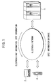
- First, referring to FIG. 1, the configuration of the information processing system according to an embodiment of the present invention is as follows.
- An information processing system according to an embodiment of the present invention, as shown in FIG. 1, has a
server apparatus 1 which provides a service using electronic map information, and aterminal apparatus 2 operated by a user who receives the service. Theserver apparatus 1 and theterminal apparatus 2 are electrically connected via an electronic network, and configured so as to enable information exchange between the apparatuses. - The above-noted term "electronic network" will be understood as encompassing any information communication network making use of electrical communications technology, including a telephone circuit, an Internet system based on TCP (Transmission Control Protocol)/IP (Internet Protocol), a WAN (Wire Area Network) , a LAN (Local Area Network) , an optical fiber communication network, a cable communication network, and a satellite communication network and the like.
- The
server apparatus 1 is formed by, for example, an information processing apparatus, such as a personal computer, a workstation, or a general-purpose computer and, as shown in FIG. 2, has aCPU 1a, aRAM 1b, a ROM 1c, acommunication controller 1d, an electronicmap information database 1e, and aspot information database 1f. - The
CPU 1a controls processing operation of theserver apparatus 1 in accordance with a program stored in the ROM 1c.
For example, theCPU 1a loads a position information/electronic map assignment program and data necessary for execution of the program stored in the ROM 1c into theRAM 1b, and executes processing so as to extract electronic map data for the area surrounding the position of theterminal apparatus 2 from within the electronicmap information database 1e, in accordance with the position information/electronic map assignment program. - The above-noted
RAM 1b provides a working area for temporary storage of data and a program to be executed by theCPU 1a. - The above-noted ROM 1c is used to store various programs and data required for the execution of these programs related to processing executed by the
server apparatus 1, such as a startup program, a position information/electronic map assignment program, and a storage processing program, for example. - In this case, the ROM 1c is configured so as to include a storage medium that is readable by the
CPU 1a, such as a magnetic or optical storage medium, or a semiconductor memory or the like, and part or all of the program and data in the ROM 1c can be downloaded via an electronic network. - The above-noted
communication controller 1d has installed in it various information communication protocols in accordance with the type of electronic network. Thecommunication controller 1d is connected to theterminal apparatus 2 in accordance with the installed information communication protocol, and sends to theterminal apparatus 2 various information in a data format in accordance with the electronic network. Thecommunication controller 1d converts various information received via the electronic network to a data format suitable for processing by theCPU 1a. - The electronic
map information database 1e stores electronic map data which is in a digital form that can be processed by theserver apparatus 1 and theterminal apparatus 2. In this case, the electronic map data can be two-dimensional electronic map data comprising xy coordinates (hereinafter longitude and latitude to be defined respectively as x and y), and can alternatively be three-dimensional electronic map data by adding height-direction (z) information to two-dimensional information so as to express objects in the two-dimensional electronic map in three dimensions. - The above-noted
spot information database 1f is used to store information with regard to positions on the electronic map stored beforehand by the service provider or by the creator of the electronic map data for such places as stores, post offices, and gasoline stations and the like (hereinafter referred to as default information), and further is used to store information with regard to positions on the electronic map stored by the user operating theterminal apparatus 2 via the electronic network (hereinafter referred to as spot information). Information with regard to positions stored in thespot information database 1f is linked to the electronic map data for the area in which the location exists. The configuration is such that it is possible for the service provider or electronic map data creator to update the default information at any arbitrary time. - The above-noted
spot information database 1f also stores user attribute information with regard to a user who receives the service provided by theserver apparatus 1. The user attribute information includes, for example, the user's name, address, telephone number, user ID, authorization password, account number for payment of service charges, and credit card number and the like. Theserver apparatus 1 refers to the information such as, for example, the user ID included in the user attribute information so as to distinguish between users, and provide service for a particular user. - The
terminal apparatus 2 is an information processing apparatus capable of information communication via an electronic network, and can be implemented as, for example a portable telephone, a simple mobile telephone, or a personal data assistant (PDA). - The above-noted portable telephone encompasses portable telephones making use of the next-generation mobile telephone communications system, such as IMT-2000 (International Mobile Telecommunications 2000) or the like. The above-noted simple mobile telephone encompasses PHS (Personal Handyphone System, Japan), PCS (Personal Communication System, US), CT2 (Codeless Telecommunications second generation, UK and France), and DECT (Digital European Codeless Telecommunication, Europe), and the like.
- The
terminal apparatus 2, as shown in FIG. 3, has aCPU 2a, aRAM 2b, aROM 2c, acommunication controller 2d, anoperation input section 2e, adisplay output section 2f, and aposition detection section 2g. - The above-noted
CPU 2a performs control of processing operations of theterminal apparatus 2 in accordance with a program stored in theROM 2c. - The above-noted
RAM 2b provides a working area for temporary storage of programs related to various processing executed by theCPU 2a and various data related to the programs. - The above-noted
ROM 2c, similar to the ROM 1c of theserver apparatus 1, includes a storage medium such as a magnetic or optical storage medium, or a semiconductor memory or the like that is readable by theCPU 2a, and the configuration can be made such that part or all of the program and data in theROM 2c can be downloaded via an electronic network. - The above-noted
communication controller 2d has installed in it various information communication protocols in accordance with the type of electronic network and the kind of theterminal apparatus 2. Thecommunication controller 2d is connected to theserver apparatus 1 in accordance with the installed information communication protocol, and sends to theserver apparatus 1 various information in a data format in accordance with the type of electronic network. Thecommunication controller 2d converts information received via the electronic network to a data format suitable for processing by theCPU 2a. - The
operation input section 2e is comprised of a general type of input device, such as a ten-key pad, a keyboard, or a touch panel or the like, and outputs an input operation signal to theCPU 2a in response to operation by a user. - The
display output section 2f is comprised of a general type of display output apparatus, such as a liquid-crystal display or the like, and displays various information in accordance with control from theCPU 2a. - The above-noted
position detection section 2g, in accordance with control from theCPU 2a, obtains information (hereinafter referred to as position information) with regard to the latitude (x), longitude (y), and height (z) and the like, for example, of a position at which theterminal apparatus 2 exists, using at least one of a communication radio signal or GPS (Global Positioning System). - In the case in which the
position detection section 2g, such as in a portable telephone or a simple portable telephone, uses a communication radio signal to perform position detection, theposition detection section 2g performs communication with the nearest communication station to obtain the position information of theterminal apparatus 2. - In the case in which the
position detection section 2g uses a GPS radio signal to perform position detection, a GPS receiving function is provided within theposition detection section 2g. This GPS receiving function generally comprises a GPS antenna for receiving a GPS radio signal, a GPS radio section, which demodulates the received GPS radio signal, and a GPS controller, which determines and outputs latitude/longitude information of the present position by calculation from the demodulated GPS radio signal. The GPS radio receiving function receives a GPS signal, which includes a precision time signal and which is transmitted by a GPS satellite, from at least three GPS satellites existing in orbit at positions from which receiving is possible, calculates the distance to the GPS satellites from the times of arrival of the GPS radio signal from each GPS satellite, taking the point at which these distances coincide to be the current position of the receiver. - The above-noted information processing system can be generally broken down into three types of processing: (1) storage processing for storing spot information into the
spot information database 1f of theserver apparatus 1 via the electronic network, (2) spot detection processing, whereby the current position of the user is detected and, when the user is in the vicinity of a position stored by the storage processing, notification is made to the user, and (3) exchange processing, whereby spot information stored in thespot information database 1f is exchanged between users. - Referring to the flowchart shown in FIG. 4, the operation of the information processing system when executing storage processing is as follows.
- According to the flowchart shown in FIG. 4, the user sets the power supply of the
terminal apparatus 2 to on and operates theoperation section 2e so as to input an execution starting command, thereby starting execution, at which point control of the storage operation transfers to the processing of step S1. - When the storage operation execution starting command is input, the user operates the
operation input section 2e so that information is also sent to theterminal apparatus 2 for identification of the location of the service provider on the electronic network, this being, for example, the telephone number (access point) of theserver apparatus 1, the IP (Internet Protocol) address, or the URL (Uniform Resource Locator) of the service provider. - As the processing of step S1, the
communication controller 2d of theterminal apparatus 2 refers to the inputted position of the service provider on the electronic network, and makes a connection to theserver apparatus 1 via the electronic network. This completes the processing of step S1, at which point control of storage processing transfers from step S1 to step S2. - As the processing of step S2, the
CPU 1a of theserver apparatus 1 generates data for a user ID and an authorization password input screen for authentication of the user operating theterminal apparatus 2. Thecommunication controller 1d of theserver apparatus 1 sends the thus generated input screen data to theterminal apparatus 2 via the electronic network. This completes the processing of step S2, at which point control of storage processing transfers from step S2 to step S3. - As the processing of step S3, the
communication controller 2d of theterminal apparatus 2 receives the input screen data sent from theserver apparatus 1 and stores the received data in theRAM 2b. When input screen data is stored in theRAM 2b, theCPU 2a controls thedisplay output section 2f so that the user ID and authorization password input screen is displayed. When the input screen is displayed, the user operates theoperation input section 2e so as to input the user ID and authorization password. When the input of the user ID and authorization password has been completed, thecommunication controller 2d converts the user ID and authorization password to an appropriate data format and send the user ID and authorization password to theserver apparatus 1, via the electronic network. This completes the processing of step S3, at which point control of storage processing transfers to step S4. - As the processing of step S4, the
communication controller 1d of theserver apparatus 1 receives the user ID and authorization password sent from theterminal apparatus 2, and inputs the received user ID and authorization password into theRAM 1b. When the user ID and authorization password are input to theRAM 1b, theCPU 1a compares the user ID and authorization password stored in thespot information database 1f to those received so as to perform authorization of the user. This completes the processing of step S4, at which point control of storage control processing transfers to step S5. - As the processing of step S5, the
CPU 1a of the determine whether or not the user ID and authorization password stored in thespot information database 1f is the same as the received user ID and authorization password, thereby determining whether or not the authentication of the user operating theterminal apparatus 2 succeeds and, in the case in which the authentication fails, control of the storage processing transfers from step S5 to step S6. - As the processing of step S6, the
CPU 1a of theserver apparatus 1 generates an error message, such as "Authentication Failed. Re-input user ID and authorization password" and thecommunication controller 1d of theserver apparatus 1 sends the thus generated error message to theterminal apparatus 2 via the electronic network. This completes the processing of step S6. The user views the error message sent from theserver apparatus 1 and performs error processing such as re-entering the user ID and authorization password, at which point control returns to step S3. - If the user authentication succeeded, however, the storage processing control transfers from step S5 to step S7.
- As the processing of step S7, the
CPU 1a of theserver apparatus 1 generates service screen data for displaying a service menu which theserver apparatus 1 provides. When this service screen data is generated, thecommunication controller 1d of theserver apparatus 1 sends the service screen data to theterminal apparatus 2 via the electronic network. This completes the processing of step S7, at which point storage processing control transfers from step S7 to step S8. - As the processing of step S8, the
communication controller 2d of theterminal apparatus 2 receives the service screen data sent from theserver apparatus 1 and stores the received data in theRAM 2b. When the service screen data is stored in theRAM 2b, theCPU 2a controls thedisplay output section 2f so as to display the service screen. When the service screen is output, the user selects the position detection menu item from the service screen, thereby issuing an instruction to start execution of detection of the position at which theterminal apparatus 2 exists. When the instruction is given to start execution of position detection, thecommunication controller 2d of theterminal apparatus 2 sends a position detection execution command to theserver apparatus 1. This completes the processing of step S8, at which point control of storage processing transfers from step S8 to step S9. - When the above-noted position detection execution command is sent, the
communication controller 2d of theterminal apparatus 2 sends information with regard to the position information acquisition method of theposition detection section 2g, such as the PHS/PCS system, the IMT-2000 system, the GPS radio receiving system or the like, to the server apparatus 1 (this being expressed as a type ID). Specifically, in the cases in which the position information acquisition method is the PHS/PCS system, the IMT-2000 system, the GPS radio receiving system, the setting is made to type I, type II, or type III respectively. By receiving this type ID, theserver apparatus 1 can control theposition detection section 2g via the electronic network, for example, to acquire position information for theterminal apparatus 2. - Within the above-noted screen, although not illustrated, there is a "New Storage Processing" icon and a "Stored Data Search Processing" icon. When the user operates the
operation input section 2e so as to select the "New Storage Processing" icon, a "Current Position Detection Processing" icon and an "Electronic Map Display Processing" icon are displayed, and when the user operates theoperation input section 2e so as to select the "Stored Data Search Processing" icon, a "Location Name Input" icon and "Keyword Input" icon are displayed. In this manner, by representing processing to instruct theterminal apparatus 2 to perform by icons, it is possible to select an appropriate processing icon by operating theoperation input section 2e, thereby enabling the user to simply start execution of the desired processing. - As the processing of step S9, the
CPU 1a of theserver apparatus 1 controls theposition detection section 2g (or theCPU 2a) of theterminal apparatus 2 according to the received type ID so as to acquire position information of theterminal apparatus 2. This completes the processing of step S9, at which point control of the storage processing transfers from step S9 to step S10. - As the processing of step S10, the
CPU 1a of theserver apparatus 1 refers to the acquired position information, and extracts from the electronicmap information database 1e electronic map data for the area surrounding the position of theterminal apparatus 2. Thecommunication controller 1d of theserver apparatus 1 sends the extracted electronic map data and position information to theterminal apparatus 2 via the electronic network. This completes the processing of step S10, at which point control of storage processing transfers from step S10 to step S11. - As the processing of step S11, the
communication controller 2d of theterminal apparatus 2 receives electronic map data and position information sent from theserver apparatus 1 and stores this electronic map data and position information in theRAM 2b. TheCPU 2a controls thedisplay output section 2f so as to display the electronic map data and position information stored in theRAM 2b. This completes the processing of step S11, at which point control of storage processing transfers from step S11 to step S12. - When electronic map data is displayed on the
display output section 2f, theCPU 2a, for example as shown in FIG. 5, displays an indicator A, in the shape of a cross, at the position of theterminal apparatus 2 on the electronic map. The indicator A can be moved on the electronic map in accordance with operation by the user via theoperation input section 2e. The electronic map displayed on thedisplay output section 2f can be zoomed in or out in accordance with operation by the user via theoperation input section 2e. - It will be understood that the above-noted indicator A is not restricted to the shape of a cross, and can alternatively take other shapes, for example a circle, a triangle, or other shape. Furthermore, although the electronic map shown in FIG. 5 is a two-dimensional map, it is alternatively possible to display a three-dimensional electronic map, and to display an indicator at the position of the
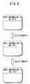
terminal apparatus 2 on the map, taking into consideration the height-direction position. In the case of a three-dimensional electronic map, it is desirable that the configuration be such that it is possible to switch the viewing point with respect to the electronic map according to the operation by the user. - As the processing of step S12, the user refers to the position of the indicator A on the electronic map, and verifies whether or not the indicator A is at a position for which information storage is desired. If the result of this verification is that the position of the indicator A is a position for which information storage is desired, the user, for example as shown in FIG. 6, presses a selection button assigned to the
operation input section 2e so as to instruct theCPU 2a to store information with regard to the position of the indicator in thespot information database 1f. - If, however, because of error in the position detection processing or error in the electronic map the position of the indicator A is not a position for which information storage is desired, the user operates the movement buttons assigned to the
operation input section 2e as shown in FIG. 6, so at to move the indicator A to a position for which information storage is desired and presses the above-noted button. This completes the processing of step S12, at which point control of the storage processing transfers from step S12 to step S13. - In the case in which the electronic map is a three-dimensional map, the user moves the indicator in three-dimensions so as to specify a position at which information storage is desired. More specifically, as shown in FIG. 7, three-dimensional data for buildings and the like on the electronic map is displayed translucently, and movement buttons assigned on the
operation input section 2e are operated to independently move the indicator A in the horizontal (xy) plane and height (z) direction. By adopting this configuration, it is possible to store information for the height (z) direction as well, for example the seventh floor of the XYZ building. - As the processing of step S13, the
CPU 2a controls thedisplay output section 2f so that a message is output to verify whether or not attribute information such as the name of a building or a telephone number is to be input. In the case in which it is desired to input attribute information, the user presses the input desired button assigned to theoperation input section 2e to send an instruction theCPU 2a to perform input processing for attribute information. This completes the processing of step S13, at which point control of storage processing transfers from step S13 to step S14. - If, however, it is not desired to input attribute information, the user presses a storage execution button assigned to the
operation input section 2e, at which point storage processing control is transferred to step S15 without going through the processing of step S14. - As the processing of step S14, the
CPU 2a controls thedisplay output section 2f so as to successively output a sequence of messages such as "Location?", "Name?", "Telephone Number?", "Characteristics?", "Comment?", and so on, thereby requesting the user to input attribute information. When the above inquiry messages are output, the user operates theoperation input section 2e so as to input in text format attribute information in response to the inquiries. This completes the processing of step S14, at which point control of storage processing transfers from step S14 to step S15. - The information regarding "Location" noted above can also be automatically input by the
terminal apparatus 2 based on acquired position information. The configuration can alternatively be such that, in the case in which attribute information with regard to a position which a user attempts to input is already stored in thespot information database 1f of theserver apparatus 1 as default information, theserver apparatus 1 sends the default information to theterminal apparatus 2, and theterminal apparatus 2 inputs the received default information instead of the user as attribute information. According to such a configuration, the burden on the user when inputting attribute information is lightened, and the user is permitted to correct or change the default information to the desired information. - When inputting this attribute information, the user can set whether or not attribute information stored in the spot detection processing (to be described below) is to be revealed to other users (this being referred to as public/private setting).
- In the case in which the
terminal apparatus 2 has a function that allows the storage of static image or movie image data, or audio data, the user can be permitted to include the image or audio data in the attribute information, in which case theCPU 2a at theterminal apparatus 2 either before or after storing attribute information outputs a verification message, for example "Store image/audio?" and when the user wishes to store such data, controls thedisplay output section 2f so as to display such icons as an "Image" or "Audio" icon. If the user selects the "Image" icon, image data input via an image input apparatus equipped with or connected to theterminal apparatus 2 is included in the attribute information. If the user selects the "Audio" icon, audio data input via an audio input apparatus equipped with or connected to theterminal apparatus 2 is included in the attribute information. This processing is completed by pressing an "End" button assigned on theoperation input section 2e. When performing this processing, if necessary the image or audio data captured in theterminal apparatus 2 can be played back so as to have the user verify whether or not it is the correct content. - As the processing of step S15, the
CPU 2a of theterminal apparatus 2 formats the input attribute information and user-specified information regarding position on the electronic map into a format such as shown in FIG. 8, and thecommunication controller 2d sends the formatted information to theserver apparatus 1 via the electronic network. This completes the processing of step S15, at which point control of the storage processing transfers from step S15 to step S16. - The formatted information, as shown in FIG. 8, includes such data as user ID, spot information ID,
terminal apparatus 2 type ID, storage date, storage time, public/private setting, related data IDs (before) (after), position information (longitude (x), latitude (y), height (z)), corresponding electronic map ID, country name, prefecture (state) name, city (town, borough) name, address number, name, telephone number, characteristics, comment, static image data, movie image data, and audio data. The user makes a setting for each of the items in the formatted information, which establishes whether or not the that item will be permitted to be transferred to another user at the time of spot information exchange processing, which is described later. - Of this formatted information, the spot information ID is left blank when the formatted information is transmitted to the
server apparatus 1. After receiving the formatted information, theserver apparatus 1 assigns a spot information ID and registers the assigned spot information ID into the formatted information. - In newly registering a spot information ID, the
server apparatus 1 registers the spot IDs before and after as the related data IDs (before) (after) of the formatted information. Specifically, in newly registering a spot information ID, theserver apparatus 1 registers the newly registered spot information ID as the related data ID (after) of the spot information immediately before. Similarly, theserver apparatus 1 registers the newly registered spot information ID as the related data ID (before) of the spot information immediately after. - Although the present explanation is described as the related data ID is assigned by the
server apparatus 1, user may rearrange the registered spot information and replace (or modify) the related data ID. In this case, the user copies to the related data ID of other spot information a spot information ID to be associated with by operating his or herterminal apparatus 2. Then, the user transmits and registers the content of the modification to theserver apparatus 1. According to such a processing, user can associate arbitrary spot information, such as associating previously registered spot information about "Central Park" with future registered spot information about "shops around the Central Park". - Although the present explanation is described as the related data ID is connected in one dimension, the related data ID may be connected derivatively such as a tree structure. According to such a processing, the spot information can be associated more systematically.
- In the case in which attribute information is not input, the data fields after the name are left blank. Of this formatted information, part or all of the user ID,
terminal apparatus 2 type ID, storage date, storage time, position information (longitude (x), latitude (y), height (z)), corresponding electronic map ID, country name, prefecture (state) name, city (town, borough) name, address number, name, and telephone number are input automatically by theterminal apparatus 2. Further, public/private setting can be done for each of the item in the formatted information. - The related data ID (before) and related data ID (after) noted above are areas used to store ID numbers of spot information related to spot information to be stored. By providing these storage areas, it is possible to store a plurality of spot information in the
spot information database 1f, as shown in FIG. 9, with a relation established therebetween, and this function enables the following types of processing. - (1) Continuous storage of spot information by the user, and use of the related data IDs to form a group of the plurality of spot information as a time series.
- (2) Automatic execution of position detection processing at a prescribed time interval, and use of the related data IDs to form a group of the continuous position history.
-
- According to the above-noted processing types (1), it is possible for the user, for example, to easily create a electronic diary with an electronic map. Because this spot information is all held in the
server apparatus 1, there is no undue burden placed on the hardware resources in theterminal apparatus 2, and it is further possible for the user to view the electronic diary on his or her home computer. Furthermore, according to the above-noted processing types (2) because it is possible for another user to verify from his or her home computer the position or movement history of a user carrying aterminal apparatus 2, it is possible, for example, to provide a service whereby the family of a child that is made to carry theterminal apparatus 2 is notified when the spot information storage is interrupted. - Although the present embodiment is described as executing the above-noted processing based on an a related data ID, it will be understood that it is alternatively possible to perform the above-noted processing based on the storage date or time that is included in the formatted information, according to which method it is possible to eliminate the need for the user to input related data ID.
- As the processing of step S16, the
communication controller 1d of theserver apparatus 1 receives the formatted data sent from theterminal apparatus 2 and stores the received formatted information in theRAM 1b. TheCPU 1a stores the formatted data in a storage area in thespot information database 1f corresponding to the user ID of the formatted information. This completes the processing of step S16, thereby completing the overall series of processing steps to perform storage processing. - Referring to the flowchart of FIG. 10, the operation of the information processing system when performing spot detection processing is as follows.
- According to the flowchart shown in FIG. 10, when the user sets the power supply of the
terminal apparatus 2 to on and sets theterminal apparatus 2 to the "automatic detection mode," control of processing is transferred to step S21. The automatic detection mode, as used herein, refers to a processing mode in which the above-noted spot detection processing provided in theterminal apparatus 2 can be executed, and enabling this mode permits the execution of the processing steps described below. Theterminal apparatus 2 can be alternatively configured so as to not have an automatic detection mode, in which case the following described processing steps are performed as long as the power is applied to theterminal apparatus 2. - As the processing of step S21, the
position detection section 2g of theterminal apparatus 2 acquires position information for theterminal apparatus 2, and sends the position information, together with the user ID of theterminal apparatus 2 to theserver apparatus 1, via the electronic network. This completes the processing of step S21, at which point control of spot detection processing transfers from step S21 to step S22. - The user can be made to input the user ID each time the automatic detection mode is set, and it is alternatively possible to store the user ID in the
ROM 2c beforehand, and to have theCPU 2a read the user ID from theROM 2c when the position information is sent. - As the processing of step S22, the
communication controller 1d of theserver apparatus 1 receives the position information of theterminal apparatus 2 and the user ID, and stores the received position information and user ID in theRAM 1b. TheCPU 1a of theserver apparatus 1 then extracts from thespot information database 1f spot information stored by the user corresponding to the user ID stored in theRAM 1b. This completes the processing of step S22, at which point control of the spot detection processing transfers from step S22 to step S23. - As the processing of step S23, the
CPU 1a refers to the position information of theterminal apparatus 2 stored in theRAM 1b and the extracted stored information, and determine whether or not the position of the extracted spot information is within a prescribed range from theterminal apparatus 2. If the result of this determination is that the extracted spot information position in not within the prescribed range from theterminal apparatus 2, the spot detection processing returns to the processing of step S21. If, however, the result of the determination is that the spot information position is within the prescribed range from theterminal apparatus 2, control of spot detection processing transfers to step S24. - The above-noted determination processing is performed, for example, by pre-specifying a detection criterion of being within several hundred meters, and by determining whether the distance between the position of the
terminal apparatus 2 and the spot information position is within this allowable distance. The tolerance range can be set by the service provider, and can alternatively be set by the user when inputting attribute information. - As the processing of step S24, the
CPU 1a of theserver apparatus 1 sends a control signal to theterminal apparatus 2 which gives notification that there is a stored spot information position in the vicinity of the position of theterminal apparatus 2. This completes the processing of step S24, at which point spot detection processing control transfers from step S24 to step S25. - As the processing of step S25, the
CPU 2a of theterminal apparatus 2 controls thedisplay output section 2f so as to display a detection flag B such as shown in FIG. 11, thereby notifying the user that there is a nearby spot information location. In response to a user request, theCPU 2a of theterminal apparatus 2 controls thedisplay output section 2f so as to output an electronic map with an indicator displayed at the spot information position. This completes the processing of step S25, at which point control of spot detection processing returns to the processing of step S21. - In the processing of the above-noted step S25, it is desirable that the user be allowed to operate the
operation input section 2e so as to scroll the electronic map, enabling the user to refer to the geography in the region surrounding the spot information position. - Although in the above-noted spot detection processing, only the spot information corresponding to the sent user ID was the target for the detection, it will be understood that it is possible for this to include spot information stored by another user. More specifically, for example, spot information can be grouped between friends and a determination can be made in the case in which there is any that is close to the position of the current
terminal apparatus 2 and also which has the public/private setting set to public. By adopting such a configuration, it is possible for a user to easily head for a location other than locations that he or she has directly stored. - The above-noted spot detection processing can also be applied in the case of a three-dimensional electronic map, and in the case in which, for example, the position of the
terminal apparatus 2 and spot information position are close as seen from the height direction, it is possible to perform the above-noted processing and display a three-dimensional electronic map on thedisplay output section 2f. - Additionally, in the above-noted spot detection processing, the case described is one in which the
server apparatus 1 detects the position at which the user exists, determines whether or not there is spot information stored in the region of the detected position, and if so makes notification. It will be understood, however, that it is further possible in the above-noted spot detection processing to have theserver apparatus 1 perform a determination whether or not stored default information in the region of the detected position has been updated by the service provider or by the electronic map creator (for example, changes in telephone numbers or store names) , and if it had been updated, to notify the user of this by sending a message such as "Information has changed. Update now?" In this case, in the case in which there is coincidence between the position at which default information is stored and the position at which spot information is stored, it is desirable that theserver apparatus 1, in response to a user request, automatically or by a manual operation by the user, perform information updating. Additionally, it is possible to have theserver apparatus 1 refer to user attribute information stored within thespot information database 1f so as to identify the user, and to notify only specific users related to specific default information when the default information has been changed. According to such processing, it is not only possible for the user to maintain the spot information in the most update condition, but also possible for the service provider provide a special service with respect to users viewing updated content, thereby enabling the providing of new services. - Additionally, although in the above-noted spot detection processing the
terminal apparatus 2 detects the position of the user and performs execution, so that the user is in a so-called passive role at the start of the processing, it is alternatively possible to input keywords expressing a place such as "Central Park," or address or position information, in response to which detection is made of spot information stored in the region of the location indicated by the input content, so that the user is in an active role in the starting of this processing. In this case, theserver apparatus 1 detects spot information stored by the user himself or herself, and also detects user spot information of other users that is set to "public," and performs display control of thedisplay output section 2f of theterminal apparatus 2 so as to display the detected spot information and the electronic map in the region near the detected spot information. According to such processing, it is possible for the user to collect information regarding regions that the user has not actually visited by referring to spot information stored by other users, thereby being able to refer to the information when going to that location. - Referring to the flowchart of FIG. 12, the operation of the information processing system when executing spot information exchange processing is as follows.
- The flowchart of FIG. 12 shows the processing that starts after the user performs the processing of step S1 through step S7 for the above-described storing processing, when the user operates the
operation input section 2e and clicks on a "keyword input" icon display on the service screen, at which point the processing control transfers to step S31. - As the processing of step S31, the
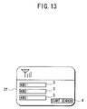
CPU 2a controls thedisplay output section 2f so as to display a keyword search screen. When the keyword search screen is displayed, the user operates theoperation input section 2e so as to input a search keyword to the keyword search screen, and press a Start Search button. When the Start Search button is pressed, thecommunication controller 2d of theterminal apparatus 2 sends the user ID and the search keyword to theserver apparatus 1 via the electronic network. This completes the processing of step S31, at which point control of exchange processing transfers from step S31 to step S32. - The above-noted keyword input screen, as shown in FIG. 13, has plurality of
keyword input boxes 3 so as to enable searching on a plurality of input keywords, and aStart Search button 4 at the bottom of the screen for starting the execution of the search. - As the processing of step S32, the
CPU 1a of theserver apparatus 1 extracts from thespot information database 1f spot information stored by the user corresponding to the sent user ID, and then further extracts from the extracted spot information related to the search keyword or keywords. TheCPU 1a extracts from the electronicmap information database 1e electronic map data in which the extracted spot information is included. This completes the processing of step S32, at which point control of the exchange processing transfers from step S32 to step S33. - As the processing of step S33, the
communication controller 1d sends the extracted spot information and electronic map data to theterminal apparatus 2 via the electronic network. This completes the processing of step S33, at which point control of the exchange processing transfers from step S33 to step S34. - As the processing of step S34, the
CPU 2a of theterminal apparatus 2 controls thedisplay output section 2f so as to display the spot information and electronic map data sent from theserver apparatus 1. This completes the processing of step S34, at which point control of the exchange processing transfers from step S34 to step S35. - When performing the processing of step S34, a Detail button, which gives an instruction to display the spot information attribute information, an Exchange button, which gives an instruction to transfer spot information to another user, and a Return button, which gives an instruction to return to the immediately previous processing, are assigned to the
operation input section 2e. - In the above-noted processing of step S34, the
CPU 2a of theterminal apparatus 2, similar to as shown in the electronic map of FIG. 5, displays an indicator at a position corresponding to the spot information location. In this case, however, if there is a plurality of spot information, theCPU 2a, before displaying the electronic map, displays the names of the spot information and the user select a name by operating theoperation input section 2e. According to the selected name, theCPU 2a displays the place of spot information. - As the processing of step S35, the user presses the "Exchange" button assigned to the
operation input section 2e so as to issue an instruction to theterminal apparatus 2 to execute exchange processing of spot information. When the "Exchange" button is selected, theCPU 2a of theterminal apparatus 2 controls thedisplay output section 2f so as to display a verifying message such as "Transfer data no. 1011?" When this message is displayed, the user operates theoperation input section 2e so as to press the OK button. This completes the processing of step S35, at which point control of the exchange processing transfers from step S35 to step S36. - As the processing of step S36, the
CPU 2a of theterminal apparatus 2 controls thedisplay output section 2f so as to display a message that prompts the user to specify which should be transferred among attribute information included in spot information selected in the processing of step S35, and also to display the attribute information included in the spot information. When this message is displayed, the user operates theoperation input section 2e so as to specify the attribute information to be transferred. This completes the processing of step S36, at which point control of the exchange processing transfers from step S36 to step S37. - As the processing of step S37, the
CPU 2a of theterminal apparatus 2 controls thedisplay output section 2f so as to display a message that prompts the input of an e-mail address as the transfer address. When this message is displayed, the user operates theoperation input section 2e so as to input the e-mail address as the transfer address. This completes the processing of step S37, at which point control of the exchange processing transfers from step S37 to step S38. - As the processing of step S38, the
CPU 2a of theterminal apparatus 2 sends information such as "Spot information sent from Mr. XX. Install now?" to the e-mail address input by the user. This completes the processing of step S38, at which point control of the exchange processing transfers from step S38 to step S39. - At this point, rather than attaching the data to be transferred to the above-noted e-mail, only the spot information user ID and attribute information to be sent (in the case in which the transfer enable/unable setting is made, only attribute information which is set for transfer enable) is attached. By doing this, it is possible to prevent trouble arising when a user not desiring the transfer of spot information is sent electronic map data or image data having a large data volume. It is also possible to perform quick transfer of spot information, even in cases in which the bandwidth of the electronic network is small.
- As the processing of step S39, the destination user receives the e-mail and determines whether or not to install the spot information by referring to the received e-mail. In the case in which the spot information is not to be installed, the destination user performs, as the processing of step S40, exchange-refusing processing to send e-mail such as "Installation of spot information is refused." to the
terminal apparatus 2 of the transmitter. On the other hand, in the case in which the spot information is to be installed, the destination user gives an instruction to start execution of the installation to the user's ownterminal apparatus 2 as the processing of step S41. When the instruction is given to start installation, thecommunication controller 2d of thedestination terminal apparatus 2 sends a control signal to start the execution of the installation to theserver apparatus 1. This control signal includes spot information ID number and information regarding the attribute information to be disclosed. This completes the processing of step S41, at which point control of the exchange processing transfers from step S41 to step S42. - As the processing of step S42, the
communication controller 1d of theserver apparatus 1 receives the control signal sent from theterminal apparatus 2, and theCPU 1a of theserver apparatus 1 extracts from thespot information database 1f spot information corresponding to the ID number of the sent spot information. TheCPU 1a copies spot information having attribute information permitting it to be disclosed into the user storage area within thespot information database 1f, enabling the destination user to make use of the transferred spot information. When this is done, theCPU 1a assigns a new ID number to the copied spot information, and notifies the user of the destination of this ID number. This completes the processing of step S42, thereby completing the overall series of steps for exchange processing. - It will be understood that rather than copying actual spot information to be transferred it is possible to record only the spot information ID number into another user' s storage area. According to this configuration, it is possible to minimize the growth in memory capacity required for the spot information database.
- Although in the above-described embodiment, the description was for the case in which spot information is exchanged via e-mail, it is alternatively possible to use a wireless communication means such as Bluetooth ® or the like to perform direct exchange of spot information between
terminal apparatuses 2. In this case, the user operates theoperation input section 2e of theterminal apparatus 2 so as to input the telephone number, IP address, or device ID or the like of theuser terminal apparatus 2 to which spot information is to be sent. It is desirable that whether spot information is to be sent directly or via aserver apparatus 1 indirectly be specifiable by the user. In the above-noted transfer processing, rather than sending the spot information itself, the spot information ID number are exchanged. - As is clear from the detailed description above, in an information processing system according to an embodiment of the present invention, because the configuration is such that the
server apparatus 1 has aspot information database 1f which stores information with regard to arbitrary locations in the electronic map data, and it is possible to view information stored in thespot information database 1f on theterminal apparatus 2 via an electronic network, it is possible for a user to store information regarding an arbitrary location on an electronic map into thespot information database 1f of theserver apparatus 1 via the electronic network, and to specify search conditions for viewing information stored in thespot information database 1f later, thereby enabling the provision of an electronic map service that matches the style of the user. - In the information processing system according to an embodiment of the present invention, because the
server apparatus 1 is configured so that when a user exists in the vicinity of the spot stored in thespot information database 1f, notification of this fact is made to the user, it is possible for a user to reliably reach the stored location, even in the case in which the user has forgotten information regarding the location that is stored in thespot information database 1f. - Additionally, in the information processing system according to an embodiment of the present invention, because the
server apparatus 1, in accordance with an instruction from theterminal apparatus 2, transfers spot information stored in thespot information database 1f between users, it is possible for the user to obtain via theterminal apparatus 2 a large amount of beneficial information, in addition to just the information provided by the service provider. - Finally, it should be noted that the foregoing embodiment is merely an exemplary descriptive form of the present invention, to which the present invention is not restricted, and that the present invention can take other various forms, within the scope of the technical concept thereof, but different from the foregoing described embodiments. It will be understood that a person skilled in the art can, based on an embodiment of the present invention, make other embodiments, and such embodiments and operating technologies are encompassed by the present invention.
- In so far as the embodiments of the invention described above are implemented, at least in part, using software-controlled data processing apparatus, it will be appreciated that a computer program providing such software control and a transmission, storage or other medium by which such a computer program is provided are envisaged as aspects of the present invention.
Claims (22)
- An information processing system comprising:a terminal apparatus comprising a position detecting means that acquires position information; anda server apparatus comprising:an electronic map information database, into which is stored electronic map data;electronic map assignment means for referring to position information sent from the terminal apparatus, extracting from the electronic map information database electronic map data for a vicinity of a position at which the terminal apparatus exists, and sending the extracted electronic map data to the terminal apparatus;a spot information database into which is stored information regarding an arbitrary location in the electronic map data sent from the terminal apparatus; andinformation extracting means for extracting from information stored in the spot information database information satisfying a search condition sent from the terminal apparatus, and sending the extracted information to the terminal apparatus.
- An information processing system according to claim 1, wherein
the server apparatus, in determining that the terminal apparatus is within a prescribed range from an arbitrary location on the electronic map data stored in the spot information database, sends prescribed information to the terminal apparatus. - An information processing system according to claim 1 or 2, wherein
information stored in the spot information database can be transferred in accordance with an operation from the terminal apparatus. - An information processing system according to any one of claims 1 to 3, wherein
the terminal apparatus applies a different identification number for each location to information regarding an arbitrary location in the electronic map data. - An information processing system according to claim 4, wherein
the terminal apparatus inputs an identification number of information related to information regarding an arbitrary location in the electronic map data. - An information processing system according to any one of claims 1 to 5, wherein
the terminal apparatus includes at least one of audio data and image data with regard to a location corresponding to information regarding an arbitrary location in the electronic map data. - An information processing system according to any one of claims 1 to 6, wherein the information extracted by the information extracting means is readable through second terminal apparatus.
- A terminal apparatus comprising:position detecting means for acquiring position information;displaying means for displaying electronic map data, including position information;input means for specifying an arbitrary location in the electronic map data, and inputting information regarding the arbitrary location; andextracting means for extracting information regarding the arbitrary location satisfying an input search condition.
- A terminal apparatus according to claim 8, further comprising:control means for controlling the displaying means when a distance between an acquired position information and an arbitrary location in the electronic map data is within a prescribed range, so that the displaying means displays a prescribed flag.
- A terminal apparatus according to claim 8 or 9, wherein
information regarding an arbitrary location in the electronic map data can be transferred. - A terminal apparatus according to any one of claims 8 to 10, further comprising:means for applying a different identification number for each location to information regarding an arbitrary location in the electronic map data.
- A terminal apparatus according to claim 11, further comprising:means for inputting an identification number of information related to information regarding an arbitrary location in the electronic map data.
- A terminal apparatus according to any one of claims 8 to 12, further comprising:means for inputting at least one of audio data and image data with regard to a location corresponding to information regarding an arbitrary location in the electronic map data.
- A method for processing information, comprising the steps of:acquiring position information of a terminal apparatus;referring to the position information, extracting electronic map data for a vicinity in which the terminal apparatus exists, and sending the extracted electronic map data to the terminal;storing information regarding an arbitrary location in electronic map data sent from the terminal apparatus; andextracting information regarding an arbitrary location in electronic map data satisfying a search condition sent from the terminal apparatus, and sending the extracted information to the terminal apparatus.
- A method for processing information according to claim 14, further comprising the step of:referring to the position information and, in determining that the terminal apparatus is within a prescribed range from an arbitrary location in the stored electronic map data, sending prescribed information to the terminal apparatus.
- A method for processing information according to claim 14 or 15, wherein
information regarding an arbitrary location in the electronic map data can be transferred. - A method for processing information according to any one of claims 14 to 16, wherein
the information regarding an arbitrary location in the electronic map data includes at least one of audio data and image data of the location. - An information processing program to be executed by a computer, comprising the steps of:acquiring position information of a terminal apparatus;referring to the position information, extracting electronic map data for a vicinity in which the terminal apparatus exists, and sending the extracted electronic map data to the terminal;storing information regarding an arbitrary location in electronic map data sent from the terminal apparatus; andextracting information regarding an arbitrary location in electronic map data satisfying a search condition sent from the terminal apparatus, and sending the extracted information to the terminal apparatus.
- A computer-readable storage medium having recording therein an information processing program to be executed by a computer, wherein the information processing program comprises the steps of:acquiring position information of a terminal apparatus;referring to the position information, extracting electronic map data for a vicinity in which the terminal apparatus exists, and sending the extracted electronic map data to the terminal;storing information regarding an arbitrary location in electronic map data sent from the terminal apparatus; andextracting information regarding an arbitrary location in electronic map data satisfying a search condition sent from the terminal apparatus, and sending the extracted information to the terminal apparatus.
- A computer-readable storage medium according to claim 19, wherein the information processing further comprises the step of:referring to the position information and, in determining that the terminal apparatus is within a prescribed range from an arbitrary location in the stored electronic map data, sending prescribed information to the terminal apparatus.
- A computer-readable storage medium according to claim 19 or 20, wherein
information regarding an arbitrary location in the electronic map data can be transferred. - A computer-readable storage medium according to any one of claims 19 to 21, wherein
the information regarding an arbitrary location in the electronic map data includes at least one of audio data and image data of the location.
Applications Claiming Priority (4)
| Application Number | Priority Date | Filing Date | Title |
|---|---|---|---|
| JP2001267834 | 2001-09-04 | ||
| JP2001267834 | 2001-09-04 | ||
| JP2002252481A JP3608740B2 (en) | 2001-09-04 | 2002-08-30 | Information processing system, terminal device, information processing method, information processing program, and computer-readable recording medium recording the information processing program |
| JP2002252481 | 2002-08-30 |
Publications (3)
| Publication Number | Publication Date |
|---|---|
| EP1288626A2 true EP1288626A2 (en) | 2003-03-05 |
| EP1288626A3 EP1288626A3 (en) | 2011-04-13 |
| EP1288626B1 EP1288626B1 (en) | 2014-08-06 |
Family
ID=26621653
Family Applications (1)
| Application Number | Title | Priority Date | Filing Date |
|---|---|---|---|
| EP02256114.6A Expired - Lifetime EP1288626B1 (en) | 2001-09-04 | 2002-09-03 | Information processing system and method providing a service using electronic map information |
Country Status (6)
| Country | Link |
|---|---|
| US (1) | US6836727B2 (en) |
| EP (1) | EP1288626B1 (en) |
| JP (1) | JP3608740B2 (en) |
| KR (1) | KR100933607B1 (en) |
| CN (1) | CN1476570A (en) |
| WO (1) | WO2003027900A1 (en) |
Cited By (4)
| Publication number | Priority date | Publication date | Assignee | Title |
|---|---|---|---|---|
| EP1718050A1 (en) | 2005-04-23 | 2006-11-02 | LG Electronics Inc. | Mobile communication terminal for providing geographical information and method thereof |
| US20130065616A1 (en) * | 2011-09-13 | 2013-03-14 | Sony Computer Entertainment Inc. | Information processing system, mobile information terminal, server, and information processing method |
| US8489591B2 (en) | 2007-01-17 | 2013-07-16 | Google Inc. | Presentation of local results |
| US10783177B2 (en) | 2007-01-17 | 2020-09-22 | Google Llc | Providing relevance-ordered categories of information |
Families Citing this family (29)
| Publication number | Priority date | Publication date | Assignee | Title |
|---|---|---|---|---|
| JP2004271901A (en) * | 2003-03-07 | 2004-09-30 | Matsushita Electric Ind Co Ltd | Map display system |
| US7356332B2 (en) * | 2003-06-09 | 2008-04-08 | Microsoft Corporation | Mobile information system for presenting information to mobile devices |
| WO2005015420A1 (en) * | 2003-08-11 | 2005-02-17 | Sony Corporation | Information processing device and communication method |
| CN1296856C (en) * | 2004-03-12 | 2007-01-24 | 倚天资讯股份有限公司 | Small frequency width picking and transfer system and method thereof |
| US20050289469A1 (en) * | 2004-06-28 | 2005-12-29 | Chandler Roger D | Context tagging apparatus, systems, and methods |
| JP4204610B2 (en) * | 2006-09-12 | 2009-01-07 | パイオニア株式会社 | Memo page information registration system, server device, and program |
| JP4284349B2 (en) * | 2006-09-29 | 2009-06-24 | 株式会社東芝 | SIP trunk gateway device |
| JP5035743B2 (en) * | 2006-10-06 | 2012-09-26 | 日本電気株式会社 | Portable information terminal and portable information terminal control program |
| US8005822B2 (en) * | 2007-01-17 | 2011-08-23 | Google Inc. | Location in search queries |
| KR101341494B1 (en) | 2007-02-13 | 2013-12-16 | 엘지전자 주식회사 | Apparatus for providing location information of hand-held devices and method thereof |
| JP2008232967A (en) * | 2007-03-23 | 2008-10-02 | Equos Research Co Ltd | Information delivery service system |
| CN101060565A (en) * | 2007-05-30 | 2007-10-24 | 华为技术有限公司 | General community information query method, device and system |
| US20090106681A1 (en) * | 2007-10-19 | 2009-04-23 | Abhinav Gupta | Method and apparatus for geographic specific search results including a map-based display |
| KR101096392B1 (en) * | 2010-01-29 | 2011-12-22 | 주식회사 팬택 | System and method for providing augmented reality |
| KR100970672B1 (en) * | 2010-03-23 | 2010-07-15 | 김동현 | According to fruit variety automatic thin skin differs a rotary angle |
| KR101003781B1 (en) * | 2010-07-12 | 2010-12-24 | 주식회사 유비샘 | System of providing realtime image for business office displayed on digital map, and method for the same |
| JP5760484B2 (en) * | 2011-02-17 | 2015-08-12 | 株式会社富士通ゼネラル | Emergency command system |
| CN102419171A (en) * | 2011-08-10 | 2012-04-18 | 王桥生 | Disaster detection electronic mapping system based on UAV aerial photography |
| CN103136767B (en) * | 2011-11-24 | 2016-08-17 | 北京图盟科技有限公司 | A kind of vectorgraph charting method and apparatus |
| CN103634740A (en) * | 2012-08-29 | 2014-03-12 | 深圳市智慧宇宙科技有限公司 | Method and device for inputting geographical location information, and terminal device |
| JP6199575B2 (en) * | 2013-02-18 | 2017-09-20 | 株式会社ぐるなび | Computer program, computer, and content usage method |
| GB201306937D0 (en) * | 2013-04-17 | 2013-05-29 | Tomtom Int Bv | Methods, devices and computer software for facilitating searching and display of locations relevant to a digital map |
| CN103440344A (en) * | 2013-09-11 | 2013-12-11 | 陈迪 | Electronic map displaying method and electronic map displaying device |
| CN104657374A (en) * | 2013-11-20 | 2015-05-27 | 富士通株式会社 | Information processing device and method and electronic equipment |
| CN105701105A (en) * | 2014-11-26 | 2016-06-22 | 联想(北京)有限公司 | Information processing method and electronic equipment |
| JP6129927B2 (en) * | 2015-10-15 | 2017-05-17 | クラリオン株式会社 | Information processing apparatus, voice operation system, and voice operation method of information processing apparatus |
| CN105571586A (en) * | 2016-01-08 | 2016-05-11 | 广东信兴科技有限公司 | Hiking navigation system |
| CN106197454A (en) * | 2016-07-28 | 2016-12-07 | 成都康普斯北斗科技有限公司 | For guiding the navigation system and method moved in |
| KR101929875B1 (en) * | 2018-05-18 | 2018-12-18 | 문경진 | Method for providing voice guidance service for vision impairment using stream live broadcast in real time |
Citations (2)
| Publication number | Priority date | Publication date | Assignee | Title |
|---|---|---|---|---|
| EP0767358A1 (en) | 1995-10-04 | 1997-04-09 | Aisin Aw Co., Ltd. | Vehicle navigation system |
| US6115611A (en) | 1996-04-24 | 2000-09-05 | Fujitsu Limited | Mobile communication system, and a mobile terminal, an information center and a storage medium used therein |
Family Cites Families (15)
| Publication number | Priority date | Publication date | Assignee | Title |
|---|---|---|---|---|
| JPH1047982A (en) | 1996-08-06 | 1998-02-20 | Sony Corp | Instrument and method for measuring location, device and method for navigation, information service method, and automobile |
| JPH10143520A (en) * | 1996-11-07 | 1998-05-29 | Toshiba Corp | Multimedia information terminal equipment |
| JPH10340178A (en) * | 1997-06-06 | 1998-12-22 | Sony Corp | Portable terminal equipment, information display method and information processing method |
| JPH1153376A (en) * | 1997-07-31 | 1999-02-26 | Nippon Telegr & Teleph Corp <Ntt> | Method and system for providing information |
| US6680694B1 (en) * | 1997-08-19 | 2004-01-20 | Siemens Vdo Automotive Corporation | Vehicle information system |
| JP2000156882A (en) | 1998-11-19 | 2000-06-06 | Nippon Telegr & Teleph Corp <Ntt> | Phs terminal position information system, position information acquiring device and phs terminal |
| JP2000331006A (en) * | 1999-05-18 | 2000-11-30 | Nippon Telegr & Teleph Corp <Ntt> | Information retrieval device |
| EP1750091B1 (en) * | 1999-06-22 | 2008-05-21 | Mitsubishi Denki Kabushiki Kaisha | Server in a navigation system |
| JP2001050762A (en) * | 1999-08-12 | 2001-02-23 | Fujitsu Ten Ltd | Navigation system |
| JP2001056805A (en) * | 1999-08-18 | 2001-02-27 | Sony Corp | Behavior predicting method and its device |
| JP2001134618A (en) * | 1999-08-26 | 2001-05-18 | Naoyuki Kageyama | Portable information system |
| JP4155374B2 (en) * | 1999-09-03 | 2008-09-24 | セコム株式会社 | Mobile safety confirmation device |
| JP3386018B2 (en) * | 1999-10-21 | 2003-03-10 | 日本電気株式会社 | Information provision system |
| JP2001195696A (en) * | 2000-01-07 | 2001-07-19 | Software Factory:Kk | System and method for monitoring position information and recording medium for recording position information monitoring program |
| JP3929894B2 (en) * | 2000-10-11 | 2007-06-13 | 三菱電機株式会社 | Location-related information mediation / acquisition method, mediation computer system, and mobile terminal |
-
2002
- 2002-08-30 JP JP2002252481A patent/JP3608740B2/en not_active Expired - Lifetime
- 2002-09-03 WO PCT/JP2002/008927 patent/WO2003027900A1/en active Application Filing
- 2002-09-03 CN CNA028031237A patent/CN1476570A/en active Pending
- 2002-09-03 EP EP02256114.6A patent/EP1288626B1/en not_active Expired - Lifetime
- 2002-09-03 KR KR1020037007475A patent/KR100933607B1/en active IP Right Grant
- 2002-09-04 US US10/234,757 patent/US6836727B2/en not_active Expired - Lifetime
Patent Citations (2)
| Publication number | Priority date | Publication date | Assignee | Title |
|---|---|---|---|---|
| EP0767358A1 (en) | 1995-10-04 | 1997-04-09 | Aisin Aw Co., Ltd. | Vehicle navigation system |
| US6115611A (en) | 1996-04-24 | 2000-09-05 | Fujitsu Limited | Mobile communication system, and a mobile terminal, an information center and a storage medium used therein |
Cited By (9)
| Publication number | Priority date | Publication date | Assignee | Title |
|---|---|---|---|---|
| EP1718050A1 (en) | 2005-04-23 | 2006-11-02 | LG Electronics Inc. | Mobile communication terminal for providing geographical information and method thereof |
| US7787890B2 (en) | 2005-04-23 | 2010-08-31 | Lg Electronics Inc. | Mobile communication terminal for providing geographical information and method thereof |
| US8489591B2 (en) | 2007-01-17 | 2013-07-16 | Google Inc. | Presentation of local results |
| US10783177B2 (en) | 2007-01-17 | 2020-09-22 | Google Llc | Providing relevance-ordered categories of information |
| US11334610B2 (en) | 2007-01-17 | 2022-05-17 | Google Llc | Providing relevance-ordered categories of information |
| US11709876B2 (en) | 2007-01-17 | 2023-07-25 | Google Llc | Providing relevance-ordered categories of information |
| US20130065616A1 (en) * | 2011-09-13 | 2013-03-14 | Sony Computer Entertainment Inc. | Information processing system, mobile information terminal, server, and information processing method |
| EP2571295A1 (en) * | 2011-09-13 | 2013-03-20 | Sony Computer Entertainment Inc. | Information processing system, mobile information terminal, server, and information processing method |
| US9002383B2 (en) | 2011-09-13 | 2015-04-07 | Sony Corporation | Information processing system, mobile information terminal, server, and information processing method |
Also Published As
| Publication number | Publication date |
|---|---|
| EP1288626B1 (en) | 2014-08-06 |
| WO2003027900A1 (en) | 2003-04-03 |
| KR100933607B1 (en) | 2009-12-23 |
| US6836727B2 (en) | 2004-12-28 |
| JP3608740B2 (en) | 2005-01-12 |
| EP1288626A3 (en) | 2011-04-13 |
| US20030078723A1 (en) | 2003-04-24 |
| JP2003196286A (en) | 2003-07-11 |
| KR20040029961A (en) | 2004-04-08 |
| CN1476570A (en) | 2004-02-18 |
Similar Documents
| Publication | Publication Date | Title |
|---|---|---|
| EP1288626B1 (en) | Information processing system and method providing a service using electronic map information | |
| JP3730967B2 (en) | Vehicle allocation system and management server | |
| US6430498B1 (en) | Portable terminal with the function of walking navigation | |
| KR100449468B1 (en) | Position information informing method and mobile communication terminal | |
| KR100450571B1 (en) | Location information providing apparatus, communication terminal, mobile communication terminal and location information providing method | |
| US20040203909A1 (en) | Systems and methods for location dependent information download to a mobile telephone | |
| US20020062263A1 (en) | Method of providing store information and store information server | |
| JPH11282863A (en) | Information presentation system and information presenting method | |
| JP2004214875A (en) | Communication terminal and radio wave state management apparatus utilizing communication terminal | |
| JP4290722B2 (en) | Information management server, communication device between portable terminals, portable terminal, and information providing method | |
| WO2002013061A1 (en) | Server apparatus for processing information according to information about position of terminal | |
| JP4335611B2 (en) | Location information providing method and location information providing program | |
| JP2008206126A (en) | Communication device, managing device, control method, program, and recording medium | |
| KR20060012390A (en) | Mobile satation with function of operating application on lacation based and method thereof | |
| JP3511980B2 (en) | Information display method and system using network | |
| JPH1013946A (en) | Portable information terminal | |
| JP2002073630A (en) | Terminal retrieval device, position information processing system and storage medium | |
| KR20010047166A (en) | Method for providing navigation service using a mobile communication system | |
| JP2009141764A (en) | System and method for providing position information | |
| WO2002098148A2 (en) | Data communication system | |
| JP2002189908A (en) | Digital contents reservation and delivery system, recording medium for program for contents server, and recording medium for program for downloading terminal | |
| JP2003134220A (en) | Telephone number information providing system, information processor and information processing method | |
| KR100574653B1 (en) | System and method for providing location information of mobile communication terminal on automatic response system | |
| JP2001177651A (en) | Information providing system | |
| JP3502810B2 (en) | Position correspondence information providing apparatus, position correspondence information provision method, and communication terminal |
Legal Events
| Date | Code | Title | Description |
|---|---|---|---|
| PUAI | Public reference made under article 153(3) epc to a published international application that has entered the european phase |
Free format text: ORIGINAL CODE: 0009012 |
|
| AK | Designated contracting states |
Kind code of ref document: A2 Designated state(s): AT BE BG CH CY CZ DE DK EE ES FI FR GB GR IE IT LI LU MC NL PT SE SK TR Designated state(s): AT BE BG CH CY CZ DE DK EE ES FI FR GB GR IE IT LI LU MC NL PT SE SK TR |
|
| AX | Request for extension of the european patent |
Extension state: AL LT LV MK RO SI |
|
| PUAL | Search report despatched |
Free format text: ORIGINAL CODE: 0009013 |
|
| AK | Designated contracting states |
Kind code of ref document: A3 Designated state(s): AT BE BG CH CY CZ DE DK EE ES FI FR GB GR IE IT LI LU MC NL PT SE SK TR |
|
| AX | Request for extension of the european patent |
Extension state: AL LT LV MK RO SI |
|
| 17P | Request for examination filed |
Effective date: 20110324 |
|
| 17Q | First examination report despatched |
Effective date: 20110415 |
|
| AKX | Designation fees paid |
Designated state(s): DE ES FR GB IT |
|
| RAP1 | Party data changed (applicant data changed or rights of an application transferred) |
Owner name: SONY COMPUTER ENTERTAINMENT INCORPORATED |
|
| RAP1 | Party data changed (applicant data changed or rights of an application transferred) |
Owner name: SONY COMPUTER ENTERTAINMENT INC. |
|
| REG | Reference to a national code |
Ref country code: DE Ref legal event code: R079 Ref document number: 60246504 Country of ref document: DE Free format text: PREVIOUS MAIN CLASS: G01C0021340000 Ipc: G01C0021360000 |
|
| GRAP | Despatch of communication of intention to grant a patent |
Free format text: ORIGINAL CODE: EPIDOSNIGR1 |
|
| RIC1 | Information provided on ipc code assigned before grant |
Ipc: G01C 21/36 20060101AFI20140212BHEP Ipc: G09B 29/10 20060101ALI20140212BHEP |
|
| INTG | Intention to grant announced |
Effective date: 20140228 |
|
| GRAS | Grant fee paid |
Free format text: ORIGINAL CODE: EPIDOSNIGR3 |
|
| GRAA | (expected) grant |
Free format text: ORIGINAL CODE: 0009210 |
|
| AK | Designated contracting states |
Kind code of ref document: B1 Designated state(s): DE ES FR GB IT |
|
| REG | Reference to a national code |
Ref country code: GB Ref legal event code: FG4D |
|
| REG | Reference to a national code |
Ref country code: DE Ref legal event code: R096 Ref document number: 60246504 Country of ref document: DE Effective date: 20140918 |
|
| PG25 | Lapsed in a contracting state [announced via postgrant information from national office to epo] |
Ref country code: ES Free format text: LAPSE BECAUSE OF FAILURE TO SUBMIT A TRANSLATION OF THE DESCRIPTION OR TO PAY THE FEE WITHIN THE PRESCRIBED TIME-LIMIT Effective date: 20140806 |
|
| PG25 | Lapsed in a contracting state [announced via postgrant information from national office to epo] |
Ref country code: IT Free format text: LAPSE BECAUSE OF FAILURE TO SUBMIT A TRANSLATION OF THE DESCRIPTION OR TO PAY THE FEE WITHIN THE PRESCRIBED TIME-LIMIT Effective date: 20140806 |
|
| REG | Reference to a national code |
Ref country code: DE Ref legal event code: R097 Ref document number: 60246504 Country of ref document: DE |
|
| PLBE | No opposition filed within time limit |
Free format text: ORIGINAL CODE: 0009261 |
|
| STAA | Information on the status of an ep patent application or granted ep patent |
Free format text: STATUS: NO OPPOSITION FILED WITHIN TIME LIMIT |
|
| 26N | No opposition filed |
Effective date: 20150507 |
|
| REG | Reference to a national code |
Ref country code: FR Ref legal event code: PLFP Year of fee payment: 14 |
|
| REG | Reference to a national code |
Ref country code: FR Ref legal event code: PLFP Year of fee payment: 15 |
|
| REG | Reference to a national code |
Ref country code: FR Ref legal event code: PLFP Year of fee payment: 16 |
|
| REG | Reference to a national code |
Ref country code: FR Ref legal event code: PLFP Year of fee payment: 17 |
|
| PGFP | Annual fee paid to national office [announced via postgrant information from national office to epo] |
Ref country code: FR Payment date: 20210812 Year of fee payment: 20 |
|
| PGFP | Annual fee paid to national office [announced via postgrant information from national office to epo] |
Ref country code: DE Payment date: 20210727 Year of fee payment: 20 Ref country code: GB Payment date: 20210728 Year of fee payment: 20 |
|
| REG | Reference to a national code |
Ref country code: DE Ref legal event code: R071 Ref document number: 60246504 Country of ref document: DE |
|
| REG | Reference to a national code |
Ref country code: GB Ref legal event code: PE20 Expiry date: 20220902 |
|
| PG25 | Lapsed in a contracting state [announced via postgrant information from national office to epo] |
Ref country code: GB Free format text: LAPSE BECAUSE OF EXPIRATION OF PROTECTION Effective date: 20220902 |