EP1285808A1 - Method and means of controlling and regulating a vehicle - Google Patents
Method and means of controlling and regulating a vehicle Download PDFInfo
- Publication number
- EP1285808A1 EP1285808A1 EP02020597A EP02020597A EP1285808A1 EP 1285808 A1 EP1285808 A1 EP 1285808A1 EP 02020597 A EP02020597 A EP 02020597A EP 02020597 A EP02020597 A EP 02020597A EP 1285808 A1 EP1285808 A1 EP 1285808A1
- Authority
- EP
- European Patent Office
- Prior art keywords
- vehicle
- speed
- acceleration
- distance
- signal
- Prior art date
- Legal status (The legal status is an assumption and is not a legal conclusion. Google has not performed a legal analysis and makes no representation as to the accuracy of the status listed.)
- Ceased
Links
- 238000000034 method Methods 0.000 title claims abstract description 163
- 230000001105 regulatory effect Effects 0.000 title claims abstract description 16
- 230000001276 controlling effect Effects 0.000 title claims abstract description 11
- 230000001133 acceleration Effects 0.000 claims abstract description 227
- 230000006870 function Effects 0.000 claims description 88
- 230000033228 biological regulation Effects 0.000 claims description 24
- 230000001419 dependent effect Effects 0.000 claims description 24
- 230000015654 memory Effects 0.000 claims description 24
- 230000007704 transition Effects 0.000 claims description 22
- 230000008569 process Effects 0.000 claims description 19
- 238000001914 filtration Methods 0.000 claims description 15
- 230000008859 change Effects 0.000 claims description 13
- 230000009467 reduction Effects 0.000 claims description 12
- 230000000694 effects Effects 0.000 claims description 11
- 238000012937 correction Methods 0.000 claims description 9
- 238000001514 detection method Methods 0.000 claims description 8
- 230000007423 decrease Effects 0.000 claims description 7
- 230000010354 integration Effects 0.000 claims description 6
- 230000003321 amplification Effects 0.000 claims description 5
- 238000012544 monitoring process Methods 0.000 claims description 5
- 238000003199 nucleic acid amplification method Methods 0.000 claims description 5
- 238000005259 measurement Methods 0.000 claims description 4
- 230000002123 temporal effect Effects 0.000 claims description 4
- 238000009499 grossing Methods 0.000 claims description 3
- 238000004088 simulation Methods 0.000 claims description 3
- 230000000295 complement effect Effects 0.000 claims description 2
- 238000013016 damping Methods 0.000 claims description 2
- 230000036962 time dependent Effects 0.000 claims description 2
- 230000007257 malfunction Effects 0.000 claims 2
- 230000003287 optical effect Effects 0.000 claims 1
- 238000004904 shortening Methods 0.000 claims 1
- 238000012546 transfer Methods 0.000 claims 1
- 230000002829 reductive effect Effects 0.000 description 11
- 230000006399 behavior Effects 0.000 description 9
- 238000004364 calculation method Methods 0.000 description 8
- 230000008901 benefit Effects 0.000 description 7
- 238000010586 diagram Methods 0.000 description 6
- 239000012530 fluid Substances 0.000 description 6
- 238000012545 processing Methods 0.000 description 5
- 238000001228 spectrum Methods 0.000 description 5
- 230000005540 biological transmission Effects 0.000 description 4
- 238000006243 chemical reaction Methods 0.000 description 4
- 230000003247 decreasing effect Effects 0.000 description 4
- 238000011161 development Methods 0.000 description 4
- 238000011156 evaluation Methods 0.000 description 4
- 230000004044 response Effects 0.000 description 4
- 238000003825 pressing Methods 0.000 description 3
- 239000000243 solution Substances 0.000 description 3
- 238000002604 ultrasonography Methods 0.000 description 3
- 239000002131 composite material Substances 0.000 description 2
- 230000006872 improvement Effects 0.000 description 2
- 238000011835 investigation Methods 0.000 description 2
- 238000007639 printing Methods 0.000 description 2
- 230000035484 reaction time Effects 0.000 description 2
- 230000002787 reinforcement Effects 0.000 description 2
- 238000005070 sampling Methods 0.000 description 2
- 230000002269 spontaneous effect Effects 0.000 description 2
- 230000009471 action Effects 0.000 description 1
- 230000003213 activating effect Effects 0.000 description 1
- 230000006978 adaptation Effects 0.000 description 1
- 238000013459 approach Methods 0.000 description 1
- 238000004422 calculation algorithm Methods 0.000 description 1
- 238000010276 construction Methods 0.000 description 1
- 230000036461 convulsion Effects 0.000 description 1
- 230000008878 coupling Effects 0.000 description 1
- 230000001934 delay Effects 0.000 description 1
- 238000009795 derivation Methods 0.000 description 1
- 238000009826 distribution Methods 0.000 description 1
- 238000005516 engineering process Methods 0.000 description 1
- 230000003203 everyday effect Effects 0.000 description 1
- 238000002347 injection Methods 0.000 description 1
- 239000007924 injection Substances 0.000 description 1
- 230000003993 interaction Effects 0.000 description 1
- 230000002452 interceptive effect Effects 0.000 description 1
- 230000007774 longterm Effects 0.000 description 1
- 230000007935 neutral effect Effects 0.000 description 1
- 230000036961 partial effect Effects 0.000 description 1
- 230000010363 phase shift Effects 0.000 description 1
- 238000012887 quadratic function Methods 0.000 description 1
- 230000002441 reversible effect Effects 0.000 description 1
- 230000003068 static effect Effects 0.000 description 1
- 238000011144 upstream manufacturing Methods 0.000 description 1
Images


Classifications
-
- B—PERFORMING OPERATIONS; TRANSPORTING
- B60—VEHICLES IN GENERAL
- B60R—VEHICLES, VEHICLE FITTINGS, OR VEHICLE PARTS, NOT OTHERWISE PROVIDED FOR
- B60R16/00—Electric or fluid circuits specially adapted for vehicles and not otherwise provided for; Arrangement of elements of electric or fluid circuits specially adapted for vehicles and not otherwise provided for
-
- B—PERFORMING OPERATIONS; TRANSPORTING
- B60—VEHICLES IN GENERAL
- B60W—CONJOINT CONTROL OF VEHICLE SUB-UNITS OF DIFFERENT TYPE OR DIFFERENT FUNCTION; CONTROL SYSTEMS SPECIALLY ADAPTED FOR HYBRID VEHICLES; ROAD VEHICLE DRIVE CONTROL SYSTEMS FOR PURPOSES NOT RELATED TO THE CONTROL OF A PARTICULAR SUB-UNIT
- B60W30/00—Purposes of road vehicle drive control systems not related to the control of a particular sub-unit, e.g. of systems using conjoint control of vehicle sub-units, or advanced driver assistance systems for ensuring comfort, stability and safety or drive control systems for propelling or retarding the vehicle
- B60W30/14—Adaptive cruise control
- B60W30/16—Control of distance between vehicles, e.g. keeping a distance to preceding vehicle
-
- B—PERFORMING OPERATIONS; TRANSPORTING
- B60—VEHICLES IN GENERAL
- B60K—ARRANGEMENT OR MOUNTING OF PROPULSION UNITS OR OF TRANSMISSIONS IN VEHICLES; ARRANGEMENT OR MOUNTING OF PLURAL DIVERSE PRIME-MOVERS IN VEHICLES; AUXILIARY DRIVES FOR VEHICLES; INSTRUMENTATION OR DASHBOARDS FOR VEHICLES; ARRANGEMENTS IN CONNECTION WITH COOLING, AIR INTAKE, GAS EXHAUST OR FUEL SUPPLY OF PROPULSION UNITS IN VEHICLES
- B60K31/00—Vehicle fittings, acting on a single sub-unit only, for automatically controlling vehicle speed, i.e. preventing speed from exceeding an arbitrarily established velocity or maintaining speed at a particular velocity, as selected by the vehicle operator
- B60K31/0008—Vehicle fittings, acting on a single sub-unit only, for automatically controlling vehicle speed, i.e. preventing speed from exceeding an arbitrarily established velocity or maintaining speed at a particular velocity, as selected by the vehicle operator including means for detecting potential obstacles in vehicle path
-
- B—PERFORMING OPERATIONS; TRANSPORTING
- B60—VEHICLES IN GENERAL
- B60K—ARRANGEMENT OR MOUNTING OF PROPULSION UNITS OR OF TRANSMISSIONS IN VEHICLES; ARRANGEMENT OR MOUNTING OF PLURAL DIVERSE PRIME-MOVERS IN VEHICLES; AUXILIARY DRIVES FOR VEHICLES; INSTRUMENTATION OR DASHBOARDS FOR VEHICLES; ARRANGEMENTS IN CONNECTION WITH COOLING, AIR INTAKE, GAS EXHAUST OR FUEL SUPPLY OF PROPULSION UNITS IN VEHICLES
- B60K31/00—Vehicle fittings, acting on a single sub-unit only, for automatically controlling vehicle speed, i.e. preventing speed from exceeding an arbitrarily established velocity or maintaining speed at a particular velocity, as selected by the vehicle operator
- B60K31/02—Vehicle fittings, acting on a single sub-unit only, for automatically controlling vehicle speed, i.e. preventing speed from exceeding an arbitrarily established velocity or maintaining speed at a particular velocity, as selected by the vehicle operator including electrically actuated servomechanism including an electric control system or a servomechanism in which the vehicle velocity affecting element is actuated electrically
- B60K31/04—Vehicle fittings, acting on a single sub-unit only, for automatically controlling vehicle speed, i.e. preventing speed from exceeding an arbitrarily established velocity or maintaining speed at a particular velocity, as selected by the vehicle operator including electrically actuated servomechanism including an electric control system or a servomechanism in which the vehicle velocity affecting element is actuated electrically and means for comparing one electrical quantity, e.g. voltage, pulse, waveform, flux, or the like, with another quantity of a like kind, which comparison means is involved in the development of an electrical signal which is fed into the controlling means
- B60K31/042—Vehicle fittings, acting on a single sub-unit only, for automatically controlling vehicle speed, i.e. preventing speed from exceeding an arbitrarily established velocity or maintaining speed at a particular velocity, as selected by the vehicle operator including electrically actuated servomechanism including an electric control system or a servomechanism in which the vehicle velocity affecting element is actuated electrically and means for comparing one electrical quantity, e.g. voltage, pulse, waveform, flux, or the like, with another quantity of a like kind, which comparison means is involved in the development of an electrical signal which is fed into the controlling means where at least one electrical quantity is set by the vehicle operator
- B60K31/045—Vehicle fittings, acting on a single sub-unit only, for automatically controlling vehicle speed, i.e. preventing speed from exceeding an arbitrarily established velocity or maintaining speed at a particular velocity, as selected by the vehicle operator including electrically actuated servomechanism including an electric control system or a servomechanism in which the vehicle velocity affecting element is actuated electrically and means for comparing one electrical quantity, e.g. voltage, pulse, waveform, flux, or the like, with another quantity of a like kind, which comparison means is involved in the development of an electrical signal which is fed into the controlling means where at least one electrical quantity is set by the vehicle operator in a memory, e.g. a capacitor
- B60K31/047—Vehicle fittings, acting on a single sub-unit only, for automatically controlling vehicle speed, i.e. preventing speed from exceeding an arbitrarily established velocity or maintaining speed at a particular velocity, as selected by the vehicle operator including electrically actuated servomechanism including an electric control system or a servomechanism in which the vehicle velocity affecting element is actuated electrically and means for comparing one electrical quantity, e.g. voltage, pulse, waveform, flux, or the like, with another quantity of a like kind, which comparison means is involved in the development of an electrical signal which is fed into the controlling means where at least one electrical quantity is set by the vehicle operator in a memory, e.g. a capacitor the memory being digital
-
- B—PERFORMING OPERATIONS; TRANSPORTING
- B60—VEHICLES IN GENERAL
- B60T—VEHICLE BRAKE CONTROL SYSTEMS OR PARTS THEREOF; BRAKE CONTROL SYSTEMS OR PARTS THEREOF, IN GENERAL; ARRANGEMENT OF BRAKING ELEMENTS ON VEHICLES IN GENERAL; PORTABLE DEVICES FOR PREVENTING UNWANTED MOVEMENT OF VEHICLES; VEHICLE MODIFICATIONS TO FACILITATE COOLING OF BRAKES
- B60T13/00—Transmitting braking action from initiating means to ultimate brake actuator with power assistance or drive; Brake systems incorporating such transmitting means, e.g. air-pressure brake systems
- B60T13/10—Transmitting braking action from initiating means to ultimate brake actuator with power assistance or drive; Brake systems incorporating such transmitting means, e.g. air-pressure brake systems with fluid assistance, drive, or release
- B60T13/66—Electrical control in fluid-pressure brake systems
-
- B—PERFORMING OPERATIONS; TRANSPORTING
- B60—VEHICLES IN GENERAL
- B60T—VEHICLE BRAKE CONTROL SYSTEMS OR PARTS THEREOF; BRAKE CONTROL SYSTEMS OR PARTS THEREOF, IN GENERAL; ARRANGEMENT OF BRAKING ELEMENTS ON VEHICLES IN GENERAL; PORTABLE DEVICES FOR PREVENTING UNWANTED MOVEMENT OF VEHICLES; VEHICLE MODIFICATIONS TO FACILITATE COOLING OF BRAKES
- B60T7/00—Brake-action initiating means
- B60T7/12—Brake-action initiating means for automatic initiation; for initiation not subject to will of driver or passenger
- B60T7/22—Brake-action initiating means for automatic initiation; for initiation not subject to will of driver or passenger initiated by contact of vehicle, e.g. bumper, with an external object, e.g. another vehicle, or by means of contactless obstacle detectors mounted on the vehicle
-
- B—PERFORMING OPERATIONS; TRANSPORTING
- B60—VEHICLES IN GENERAL
- B60T—VEHICLE BRAKE CONTROL SYSTEMS OR PARTS THEREOF; BRAKE CONTROL SYSTEMS OR PARTS THEREOF, IN GENERAL; ARRANGEMENT OF BRAKING ELEMENTS ON VEHICLES IN GENERAL; PORTABLE DEVICES FOR PREVENTING UNWANTED MOVEMENT OF VEHICLES; VEHICLE MODIFICATIONS TO FACILITATE COOLING OF BRAKES
- B60T8/00—Arrangements for adjusting wheel-braking force to meet varying vehicular or ground-surface conditions, e.g. limiting or varying distribution of braking force
- B60T8/17—Using electrical or electronic regulation means to control braking
- B60T8/172—Determining control parameters used in the regulation, e.g. by calculations involving measured or detected parameters
-
- B—PERFORMING OPERATIONS; TRANSPORTING
- B60—VEHICLES IN GENERAL
- B60T—VEHICLE BRAKE CONTROL SYSTEMS OR PARTS THEREOF; BRAKE CONTROL SYSTEMS OR PARTS THEREOF, IN GENERAL; ARRANGEMENT OF BRAKING ELEMENTS ON VEHICLES IN GENERAL; PORTABLE DEVICES FOR PREVENTING UNWANTED MOVEMENT OF VEHICLES; VEHICLE MODIFICATIONS TO FACILITATE COOLING OF BRAKES
- B60T8/00—Arrangements for adjusting wheel-braking force to meet varying vehicular or ground-surface conditions, e.g. limiting or varying distribution of braking force
- B60T8/32—Arrangements for adjusting wheel-braking force to meet varying vehicular or ground-surface conditions, e.g. limiting or varying distribution of braking force responsive to a speed condition, e.g. acceleration or deceleration
- B60T8/34—Arrangements for adjusting wheel-braking force to meet varying vehicular or ground-surface conditions, e.g. limiting or varying distribution of braking force responsive to a speed condition, e.g. acceleration or deceleration having a fluid pressure regulator responsive to a speed condition
- B60T8/36—Arrangements for adjusting wheel-braking force to meet varying vehicular or ground-surface conditions, e.g. limiting or varying distribution of braking force responsive to a speed condition, e.g. acceleration or deceleration having a fluid pressure regulator responsive to a speed condition including a pilot valve responding to an electromagnetic force
-
- B—PERFORMING OPERATIONS; TRANSPORTING
- B60—VEHICLES IN GENERAL
- B60T—VEHICLE BRAKE CONTROL SYSTEMS OR PARTS THEREOF; BRAKE CONTROL SYSTEMS OR PARTS THEREOF, IN GENERAL; ARRANGEMENT OF BRAKING ELEMENTS ON VEHICLES IN GENERAL; PORTABLE DEVICES FOR PREVENTING UNWANTED MOVEMENT OF VEHICLES; VEHICLE MODIFICATIONS TO FACILITATE COOLING OF BRAKES
- B60T8/00—Arrangements for adjusting wheel-braking force to meet varying vehicular or ground-surface conditions, e.g. limiting or varying distribution of braking force
- B60T8/32—Arrangements for adjusting wheel-braking force to meet varying vehicular or ground-surface conditions, e.g. limiting or varying distribution of braking force responsive to a speed condition, e.g. acceleration or deceleration
- B60T8/34—Arrangements for adjusting wheel-braking force to meet varying vehicular or ground-surface conditions, e.g. limiting or varying distribution of braking force responsive to a speed condition, e.g. acceleration or deceleration having a fluid pressure regulator responsive to a speed condition
- B60T8/48—Arrangements for adjusting wheel-braking force to meet varying vehicular or ground-surface conditions, e.g. limiting or varying distribution of braking force responsive to a speed condition, e.g. acceleration or deceleration having a fluid pressure regulator responsive to a speed condition connecting the brake actuator to an alternative or additional source of fluid pressure, e.g. traction control systems
-
- G—PHYSICS
- G08—SIGNALLING
- G08G—TRAFFIC CONTROL SYSTEMS
- G08G1/00—Traffic control systems for road vehicles
- G08G1/16—Anti-collision systems
- G08G1/166—Anti-collision systems for active traffic, e.g. moving vehicles, pedestrians, bikes
-
- B—PERFORMING OPERATIONS; TRANSPORTING
- B60—VEHICLES IN GENERAL
- B60T—VEHICLE BRAKE CONTROL SYSTEMS OR PARTS THEREOF; BRAKE CONTROL SYSTEMS OR PARTS THEREOF, IN GENERAL; ARRANGEMENT OF BRAKING ELEMENTS ON VEHICLES IN GENERAL; PORTABLE DEVICES FOR PREVENTING UNWANTED MOVEMENT OF VEHICLES; VEHICLE MODIFICATIONS TO FACILITATE COOLING OF BRAKES
- B60T2201/00—Particular use of vehicle brake systems; Special systems using also the brakes; Special software modules within the brake system controller
- B60T2201/02—Active or adaptive cruise control system; Distance control
-
- B—PERFORMING OPERATIONS; TRANSPORTING
- B60—VEHICLES IN GENERAL
- B60T—VEHICLE BRAKE CONTROL SYSTEMS OR PARTS THEREOF; BRAKE CONTROL SYSTEMS OR PARTS THEREOF, IN GENERAL; ARRANGEMENT OF BRAKING ELEMENTS ON VEHICLES IN GENERAL; PORTABLE DEVICES FOR PREVENTING UNWANTED MOVEMENT OF VEHICLES; VEHICLE MODIFICATIONS TO FACILITATE COOLING OF BRAKES
- B60T2230/00—Monitoring, detecting special vehicle behaviour; Counteracting thereof
- B60T2230/04—Jerk, soft-stop; Anti-jerk, reduction of pitch or nose-dive when braking
-
- B—PERFORMING OPERATIONS; TRANSPORTING
- B60—VEHICLES IN GENERAL
- B60T—VEHICLE BRAKE CONTROL SYSTEMS OR PARTS THEREOF; BRAKE CONTROL SYSTEMS OR PARTS THEREOF, IN GENERAL; ARRANGEMENT OF BRAKING ELEMENTS ON VEHICLES IN GENERAL; PORTABLE DEVICES FOR PREVENTING UNWANTED MOVEMENT OF VEHICLES; VEHICLE MODIFICATIONS TO FACILITATE COOLING OF BRAKES
- B60T2260/00—Interaction of vehicle brake system with other systems
- B60T2260/09—Complex systems; Conjoint control of two or more vehicle active control systems
-
- B—PERFORMING OPERATIONS; TRANSPORTING
- B60—VEHICLES IN GENERAL
- B60W—CONJOINT CONTROL OF VEHICLE SUB-UNITS OF DIFFERENT TYPE OR DIFFERENT FUNCTION; CONTROL SYSTEMS SPECIALLY ADAPTED FOR HYBRID VEHICLES; ROAD VEHICLE DRIVE CONTROL SYSTEMS FOR PURPOSES NOT RELATED TO THE CONTROL OF A PARTICULAR SUB-UNIT
- B60W50/00—Details of control systems for road vehicle drive control not related to the control of a particular sub-unit, e.g. process diagnostic or vehicle driver interfaces
- B60W2050/0001—Details of the control system
- B60W2050/0002—Automatic control, details of type of controller or control system architecture
- B60W2050/0012—Feedforward or open loop systems
-
- B—PERFORMING OPERATIONS; TRANSPORTING
- B60—VEHICLES IN GENERAL
- B60W—CONJOINT CONTROL OF VEHICLE SUB-UNITS OF DIFFERENT TYPE OR DIFFERENT FUNCTION; CONTROL SYSTEMS SPECIALLY ADAPTED FOR HYBRID VEHICLES; ROAD VEHICLE DRIVE CONTROL SYSTEMS FOR PURPOSES NOT RELATED TO THE CONTROL OF A PARTICULAR SUB-UNIT
- B60W50/00—Details of control systems for road vehicle drive control not related to the control of a particular sub-unit, e.g. process diagnostic or vehicle driver interfaces
- B60W2050/0001—Details of the control system
- B60W2050/0019—Control system elements or transfer functions
- B60W2050/0022—Gains, weighting coefficients or weighting functions
-
- B—PERFORMING OPERATIONS; TRANSPORTING
- B60—VEHICLES IN GENERAL
- B60W—CONJOINT CONTROL OF VEHICLE SUB-UNITS OF DIFFERENT TYPE OR DIFFERENT FUNCTION; CONTROL SYSTEMS SPECIALLY ADAPTED FOR HYBRID VEHICLES; ROAD VEHICLE DRIVE CONTROL SYSTEMS FOR PURPOSES NOT RELATED TO THE CONTROL OF A PARTICULAR SUB-UNIT
- B60W50/00—Details of control systems for road vehicle drive control not related to the control of a particular sub-unit, e.g. process diagnostic or vehicle driver interfaces
- B60W2050/0001—Details of the control system
- B60W2050/0019—Control system elements or transfer functions
- B60W2050/0028—Mathematical models, e.g. for simulation
- B60W2050/0031—Mathematical model of the vehicle
-
- B—PERFORMING OPERATIONS; TRANSPORTING
- B60—VEHICLES IN GENERAL
- B60W—CONJOINT CONTROL OF VEHICLE SUB-UNITS OF DIFFERENT TYPE OR DIFFERENT FUNCTION; CONTROL SYSTEMS SPECIALLY ADAPTED FOR HYBRID VEHICLES; ROAD VEHICLE DRIVE CONTROL SYSTEMS FOR PURPOSES NOT RELATED TO THE CONTROL OF A PARTICULAR SUB-UNIT
- B60W50/00—Details of control systems for road vehicle drive control not related to the control of a particular sub-unit, e.g. process diagnostic or vehicle driver interfaces
- B60W2050/0001—Details of the control system
- B60W2050/0043—Signal treatments, identification of variables or parameters, parameter estimation or state estimation
- B60W2050/0052—Filtering, filters
-
- B—PERFORMING OPERATIONS; TRANSPORTING
- B60—VEHICLES IN GENERAL
- B60W—CONJOINT CONTROL OF VEHICLE SUB-UNITS OF DIFFERENT TYPE OR DIFFERENT FUNCTION; CONTROL SYSTEMS SPECIALLY ADAPTED FOR HYBRID VEHICLES; ROAD VEHICLE DRIVE CONTROL SYSTEMS FOR PURPOSES NOT RELATED TO THE CONTROL OF A PARTICULAR SUB-UNIT
- B60W2510/00—Input parameters relating to a particular sub-units
- B60W2510/06—Combustion engines, Gas turbines
- B60W2510/0657—Engine torque
-
- B—PERFORMING OPERATIONS; TRANSPORTING
- B60—VEHICLES IN GENERAL
- B60W—CONJOINT CONTROL OF VEHICLE SUB-UNITS OF DIFFERENT TYPE OR DIFFERENT FUNCTION; CONTROL SYSTEMS SPECIALLY ADAPTED FOR HYBRID VEHICLES; ROAD VEHICLE DRIVE CONTROL SYSTEMS FOR PURPOSES NOT RELATED TO THE CONTROL OF A PARTICULAR SUB-UNIT
- B60W2510/00—Input parameters relating to a particular sub-units
- B60W2510/10—Change speed gearings
- B60W2510/1005—Transmission ratio engaged
-
- B—PERFORMING OPERATIONS; TRANSPORTING
- B60—VEHICLES IN GENERAL
- B60W—CONJOINT CONTROL OF VEHICLE SUB-UNITS OF DIFFERENT TYPE OR DIFFERENT FUNCTION; CONTROL SYSTEMS SPECIALLY ADAPTED FOR HYBRID VEHICLES; ROAD VEHICLE DRIVE CONTROL SYSTEMS FOR PURPOSES NOT RELATED TO THE CONTROL OF A PARTICULAR SUB-UNIT
- B60W2520/00—Input parameters relating to overall vehicle dynamics
- B60W2520/10—Longitudinal speed
- B60W2520/105—Longitudinal acceleration
-
- B—PERFORMING OPERATIONS; TRANSPORTING
- B60—VEHICLES IN GENERAL
- B60W—CONJOINT CONTROL OF VEHICLE SUB-UNITS OF DIFFERENT TYPE OR DIFFERENT FUNCTION; CONTROL SYSTEMS SPECIALLY ADAPTED FOR HYBRID VEHICLES; ROAD VEHICLE DRIVE CONTROL SYSTEMS FOR PURPOSES NOT RELATED TO THE CONTROL OF A PARTICULAR SUB-UNIT
- B60W2520/00—Input parameters relating to overall vehicle dynamics
- B60W2520/12—Lateral speed
- B60W2520/125—Lateral acceleration
-
- B—PERFORMING OPERATIONS; TRANSPORTING
- B60—VEHICLES IN GENERAL
- B60W—CONJOINT CONTROL OF VEHICLE SUB-UNITS OF DIFFERENT TYPE OR DIFFERENT FUNCTION; CONTROL SYSTEMS SPECIALLY ADAPTED FOR HYBRID VEHICLES; ROAD VEHICLE DRIVE CONTROL SYSTEMS FOR PURPOSES NOT RELATED TO THE CONTROL OF A PARTICULAR SUB-UNIT
- B60W2520/00—Input parameters relating to overall vehicle dynamics
- B60W2520/14—Yaw
-
- B—PERFORMING OPERATIONS; TRANSPORTING
- B60—VEHICLES IN GENERAL
- B60W—CONJOINT CONTROL OF VEHICLE SUB-UNITS OF DIFFERENT TYPE OR DIFFERENT FUNCTION; CONTROL SYSTEMS SPECIALLY ADAPTED FOR HYBRID VEHICLES; ROAD VEHICLE DRIVE CONTROL SYSTEMS FOR PURPOSES NOT RELATED TO THE CONTROL OF A PARTICULAR SUB-UNIT
- B60W2540/00—Input parameters relating to occupants
- B60W2540/12—Brake pedal position
-
- B—PERFORMING OPERATIONS; TRANSPORTING
- B60—VEHICLES IN GENERAL
- B60W—CONJOINT CONTROL OF VEHICLE SUB-UNITS OF DIFFERENT TYPE OR DIFFERENT FUNCTION; CONTROL SYSTEMS SPECIALLY ADAPTED FOR HYBRID VEHICLES; ROAD VEHICLE DRIVE CONTROL SYSTEMS FOR PURPOSES NOT RELATED TO THE CONTROL OF A PARTICULAR SUB-UNIT
- B60W2540/00—Input parameters relating to occupants
- B60W2540/18—Steering angle
-
- B—PERFORMING OPERATIONS; TRANSPORTING
- B60—VEHICLES IN GENERAL
- B60W—CONJOINT CONTROL OF VEHICLE SUB-UNITS OF DIFFERENT TYPE OR DIFFERENT FUNCTION; CONTROL SYSTEMS SPECIALLY ADAPTED FOR HYBRID VEHICLES; ROAD VEHICLE DRIVE CONTROL SYSTEMS FOR PURPOSES NOT RELATED TO THE CONTROL OF A PARTICULAR SUB-UNIT
- B60W2554/00—Input parameters relating to objects
- B60W2554/40—Dynamic objects, e.g. animals, windblown objects
- B60W2554/404—Characteristics
- B60W2554/4042—Longitudinal speed
-
- B—PERFORMING OPERATIONS; TRANSPORTING
- B60—VEHICLES IN GENERAL
- B60W—CONJOINT CONTROL OF VEHICLE SUB-UNITS OF DIFFERENT TYPE OR DIFFERENT FUNCTION; CONTROL SYSTEMS SPECIALLY ADAPTED FOR HYBRID VEHICLES; ROAD VEHICLE DRIVE CONTROL SYSTEMS FOR PURPOSES NOT RELATED TO THE CONTROL OF A PARTICULAR SUB-UNIT
- B60W2554/00—Input parameters relating to objects
- B60W2554/80—Spatial relation or speed relative to objects
- B60W2554/804—Relative longitudinal speed
-
- B—PERFORMING OPERATIONS; TRANSPORTING
- B60—VEHICLES IN GENERAL
- B60W—CONJOINT CONTROL OF VEHICLE SUB-UNITS OF DIFFERENT TYPE OR DIFFERENT FUNCTION; CONTROL SYSTEMS SPECIALLY ADAPTED FOR HYBRID VEHICLES; ROAD VEHICLE DRIVE CONTROL SYSTEMS FOR PURPOSES NOT RELATED TO THE CONTROL OF A PARTICULAR SUB-UNIT
- B60W2710/00—Output or target parameters relating to a particular sub-units
- B60W2710/10—Change speed gearings
- B60W2710/105—Output torque
-
- B—PERFORMING OPERATIONS; TRANSPORTING
- B60—VEHICLES IN GENERAL
- B60W—CONJOINT CONTROL OF VEHICLE SUB-UNITS OF DIFFERENT TYPE OR DIFFERENT FUNCTION; CONTROL SYSTEMS SPECIALLY ADAPTED FOR HYBRID VEHICLES; ROAD VEHICLE DRIVE CONTROL SYSTEMS FOR PURPOSES NOT RELATED TO THE CONTROL OF A PARTICULAR SUB-UNIT
- B60W2720/00—Output or target parameters relating to overall vehicle dynamics
- B60W2720/10—Longitudinal speed
- B60W2720/106—Longitudinal acceleration
-
- B—PERFORMING OPERATIONS; TRANSPORTING
- B60—VEHICLES IN GENERAL
- B60W—CONJOINT CONTROL OF VEHICLE SUB-UNITS OF DIFFERENT TYPE OR DIFFERENT FUNCTION; CONTROL SYSTEMS SPECIALLY ADAPTED FOR HYBRID VEHICLES; ROAD VEHICLE DRIVE CONTROL SYSTEMS FOR PURPOSES NOT RELATED TO THE CONTROL OF A PARTICULAR SUB-UNIT
- B60W2754/00—Output or target parameters relating to objects
- B60W2754/10—Spatial relation or speed relative to objects
- B60W2754/30—Longitudinal distance
-
- B—PERFORMING OPERATIONS; TRANSPORTING
- B60—VEHICLES IN GENERAL
- B60W—CONJOINT CONTROL OF VEHICLE SUB-UNITS OF DIFFERENT TYPE OR DIFFERENT FUNCTION; CONTROL SYSTEMS SPECIALLY ADAPTED FOR HYBRID VEHICLES; ROAD VEHICLE DRIVE CONTROL SYSTEMS FOR PURPOSES NOT RELATED TO THE CONTROL OF A PARTICULAR SUB-UNIT
- B60W30/00—Purposes of road vehicle drive control systems not related to the control of a particular sub-unit, e.g. of systems using conjoint control of vehicle sub-units, or advanced driver assistance systems for ensuring comfort, stability and safety or drive control systems for propelling or retarding the vehicle
- B60W30/08—Active safety systems predicting or avoiding probable or impending collision or attempting to minimise its consequences
- B60W30/09—Taking automatic action to avoid collision, e.g. braking and steering
-
- B—PERFORMING OPERATIONS; TRANSPORTING
- B60—VEHICLES IN GENERAL
- B60W—CONJOINT CONTROL OF VEHICLE SUB-UNITS OF DIFFERENT TYPE OR DIFFERENT FUNCTION; CONTROL SYSTEMS SPECIALLY ADAPTED FOR HYBRID VEHICLES; ROAD VEHICLE DRIVE CONTROL SYSTEMS FOR PURPOSES NOT RELATED TO THE CONTROL OF A PARTICULAR SUB-UNIT
- B60W50/00—Details of control systems for road vehicle drive control not related to the control of a particular sub-unit, e.g. process diagnostic or vehicle driver interfaces
- B60W50/08—Interaction between the driver and the control system
- B60W50/14—Means for informing the driver, warning the driver or prompting a driver intervention
Definitions
- the present application relates to improvements in Vehicle control or regulation.
- the in this application Aspects mentioned can be individually or together come together with each other. When used in combination there are special advantages.
- a first aspect of the present invention relates to a Method and device for controlling a Motor vehicle according to the preambles of claims 1 and 10.
- a well-known example of such coordination is that Interplay between driver request (accelerator pedal), cruise control and vehicle sequence control.
- the vehicle sequence control gives if necessary, the target speeds suitable for the cruise control before so that the vehicle sequence control her Can achieve the regulatory goal.
- This is the vehicle sequence control connected in series to the cruise control.
- the driver's request usually in the form of accelerator pedal actuation integrated into the system so that it automatically generated signals overwrites.
- the above system or method has the disadvantage that the dynamic behavior of the follow-up scheme no better than that of the cruise control. It has been shown that the dynamic Behavior is not enough.
- the object of this aspect of the invention is a method and to provide a device for vehicle control, with those suitable reference variables for vehicle control can be determined.
- control interventions do not use the detour speed controller but direct, comparable to that Driver intervention, braking and accelerating.
- Driver interventions change the longitudinal acceleration of the vehicle; the longitudinal acceleration is chosen as the controlled variable.
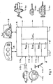
- 1 shows various sources for setpoint specifications.
- 1-17a-c designate various sensors, according to which target accelerations are generated.
- 1-17a denotes a distance sensor with which the distance to the vehicle in front is determined.
- a vehicle sequence control 11a determines a vehicle acceleration a sequence which is suitable for the vehicle sequence control .
- 1-17b symbolize buttons that are located on the steering wheel or a steering column switch with which the cruise control can be influenced.
- the keyboard can have keys for setting, increasing, decreasing or resuming a specific target speed.
- the cruise control 1-11b determines an acceleration a temp desired to achieve its control objective.
- pedals 1-17c (brake pedal and accelerator, possibly clutch), a driver can directly influence the vehicle as desired.
- a suitable control 1-11c determines an acceleration a pedal from these variables and from other operating conditions.
- Reference number 1-11d symbolizes further sources of intermediate acceleration values, for example a curve speed adjustment or a driving stability control.
- This acceleration a Lsoll is input to an acceleration controller 1-13, which actuates the various vehicle actuators such as brakes 1-14a and / or transmission 1-14b and / or motor 1-14c according to this requirement.
- the coordinator device 1-12 can have various configurations. In a simple case, the coordination device 1-12 is designed in such a way that it outputs the smallest of all the values entered to it as the setpoint a Lsoll to the acceleration controller 1-13. "The smallest value" is to be understood in the mathematical sense, ie taking the sign into account.
- the coordination device 1-12 can, however, also form a weighted average from the values received by it, it being possible for the weights to be adapted or shifted depending on the situation.
- the state variables in and around the vehicle are detected by sensors 1-16 and 1-17a-c. The values supplied by these sensors can be used to control the weighting or the selection of individual target acceleration values entered by the coordinator device 1-12.
- the individual components 1-11a-d generating setpoints lie and work functionally parallel to each other. This makes it possible to give the individual components different characteristics without such characteristics being blurred by subsequent components. For example, it is possible to set the cruise control to "soft", while the distance sequence control can be set to "immediate”.
- the coordinator device 1-12 can then, for example in the case of competing signals from cruise control 1-11b and vehicle sequence control 1-11a, select the acceleration a sequence output by the vehicle sequence control 1-11a and supply it to the acceleration controller 1-13 as acceleration a Lsoll without the "immediate” characteristic of the vehicle sequence control being blurred again by the "soft" characteristic of the cruise control 1-11b.
- the output result of the vehicle sequence control would be evaluated by the downstream cruise control and thus possibly washed out.
- the components 1-11a - 1-11d that generate the setpoints are not limited to the examples above.
- vehicle control can include other components are added, which generate individual target values. she can run in parallel to the other components that already exist be switched and coordinated by the Coordinator device 1-12 are included.
- control and security logic 1-18 monitors, which ensures the control process and appropriate measures if individual components fail like partial shutdown, full shutdown or similar grasps.
- a Adaptation of different characteristic curves to different driver classes about monitoring driver behavior, the Vehicle reaction and the environment is also possible.
- the control and safety logic 1-18 monitors also user interface 1-15 by using your appropriate Signals are supplied and received signals received from it become.
- Another aspect of the present invention relates to a Method and device for vehicle sequence control.
- Curve 3-10 shows the speed of a vehicle in front, curve 3-11 the speed of an immediately following vehicle.
- the starting point is now the steady state, in which the two vehicles drive one behind the other at constant speed v 0 . It is then assumed that the vehicle in front brakes at time t 1 and then continues at reduced speed v 1 . From time t 1, curve 3-10 thus shows a drop in speed from v 0 to v 1 . This results in a state that the speed of the following vehicle (curve 3-11) is higher than the speed of the preceding vehicle (curve 3-10) from time t 1 . In order to prevent the rearward collision, the following vehicle must also brake sooner or later. Now the following vehicle cannot immediately follow the speed change of the preceding vehicle.
- time t 4 Up to time t 4 , at which the speed of the following vehicle has adjusted to that of the preceding vehicle, the speed of the following vehicle is higher than that of the preceding vehicle. Therefore, the distance between the two vehicles decreases until time t 4 .
- the reduction in distance corresponds to the area (integral) between the two curves.
- the following vehicle is braked further. This is usually done by reducing the speed until the original distance or a distance corresponding to the new speed is restored between the two vehicles. In Fig. 9 this is assumed at time t 5 .
- ICC regulation Intelligent Cruise Control
- one ICC regulation has response times that lead to that there are distances between vehicles running behind one another decrease when the vehicle in front brakes. Such reductions in distance are achieved by braking of the following vehicle below the minimum speed of the vehicle in front, as referenced described in FIG.
- the object of this aspect of the invention is a method and to specify a device for driving speed control, with the effects of response or delay times be reduced or avoided.
- the controller 10 shows a distance controller. It receives input signals, that of a comparatively sophisticated one Sensors are supplied. Among other things, it receives signals the distance and relative speed of your own Vehicle from or in front of a vehicle in front Specify vehicle. The controller also knows its own Speed. The controller is designed, at least the above input signals control signals for the to produce your own vehicle. These control signals can Control signals include both acceleration as well as braking the vehicle. An acceleration of the vehicle can be achieved by the Distance controller outputs signals that, for example, the digitized Correspond to signals from an accelerator pedal. This Output signals are then from a subsequent engine control processed in a suitable manner. Just as direct are Control signals for the throttle valve conceivable, if necessary in connection with signals for the injection duration, to directly increase the speed. Via accelerator pedal and throttle signals can also be a decrease the vehicle speed are caused (engine brake). In addition, the ICC controller can output signals that an active braking of the vehicle by the Brake system is controlled directly or indirectly.
- Fig. 11 shows the case that the ICC control the speed of the following vehicle (Curve 3-31) regulates so that the braking of the vehicle in front Vehicle also braked with a time delay will, but the speed of the vehicle in front is not undercut.
- FIG. 11 shows the control aim of not letting the speed of the following vehicle drop below the speed of the preceding vehicle.
- the speed of the following vehicle (curve 3-31) is higher than the speed of the preceding vehicle (curve 3-30).
- the distance between the two vehicles thus decreases between the times mentioned.
- the reduction in distance corresponds to the integral over the relative speed.
- the reduction in distance is shown in the lower part of FIG. 11. In the upper part the reduction in distance corresponds figuratively to the area between curves 3-30 and 3-31, in the lower part the value is marked as - ⁇ .
- the distance between the two vehicles between t 9 and t 10 has decreased by this value - ⁇ .
- Fig. 11 shows the case in which the preceding vehicle accelerates again (time t 11 ).
- the ICC control can be designed such that it does not immediately follow the acceleration of the vehicle in front, but only with a time delay at time t 12 .
- the following vehicle is then accelerated until it has resumed the speed of the preceding vehicle at time t 13 .
- the distance is then preferably the same as before time t 9 .
- the time offset t 12 -t 11 between the driver's own acceleration and acceleration of the preceding vehicle is preferably as large as the time offset between the beginning of the braking of the preceding vehicle and the beginning of the braking of the following vehicle.
- the ICC control can be designed such that it specifies the target speed of the following vehicle so that it is slightly below the speed v 1 of the preceding vehicle. This somewhat reduced speed is preferably specified only after a certain period of time has elapsed after the lower constant speed v 1 (time t 10 ) has been reached. This reduced default speed is maintained until the desired distance between the vehicles for the speed v 1 is reached.
- the ICC control can also be designed in such a way that, in the event that braking of the vehicle in front is detected, it allows briefly comparatively smaller distances than in the stationary state between the two vehicles. This permitting of shorter distances can also be taken over for a period in which the vehicle in front has reached a constant lower speed after braking. In FIG. 11 that would be the speed v 1 from the time t 14 .
- the minimum distances permitted in the steady state or the minimum distances permitted in dynamic transition states can be speed-dependent and can be stored in tables or maps.
- the distance actually intended for steady-state conditions can be set by braking one's own vehicle slightly until the distance between the steady-state condition and, if applicable, the corresponding speed, between the both vehicles are set again. Then you can accelerate until the two vehicles have the same speed.
- the regulation described above can be made by a suitable programmed computer to be implemented using the above takes the input variables mentioned and also described Control signals delivers. Such systems are time-discretely sampled, the signal processing takes place digital.
- Another aspect of the present invention relates to a Method and device for generating a Vehicle speed indicating speed signal.
- control becomes an accurate speed signal needed. So far the speed signal either delivered directly from a sensor or one Output taken from an ABS control. Such signals are but heavily overlaid with noise, so that in some Applications, e.g. in ICC systems, not easily can be used.
- the object of this aspect of the invention is a method and to provide a device with which an accurate speed signal received with little delay can be.
- noise does not disturb the speed signal evenly distributed over the frequency range, but that there are individually distinguishable interference components.
- the inventors found that, on the one hand, parts that can be localized by a frequency band and, on the other hand, higher-frequency parts disturb the speed signal.
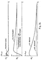
- Fig. 12 shows the spectrum of a speed signal, as is usually used for engine or vehicle control.
- Such disturbances have a significant influence on the accuracy or reliability of the vehicle control and must therefore be suppressed.
- FIG. 13 shows a block diagram of an embodiment according to the invention for suppressing disturbances in the speed signal.
- the disturbed input speed signal v E passes through a low-pass filter 4-20 and a band-stop filter 4-21. Both filters 4-20 and 4-21 need not be provided. One of the two may be sufficient, the connection in series, possibly in the reverse order, leading to very good results.
- the fact when filtering the input speed signal v E, the fact must be taken into account that the acceleration of the vehicle can lead to amounts of speed change in the disturbed input signal that are comparable in size or greater than disturbing ripple components in the signal. Such components must not simply be filtered out, otherwise the filtered signal would not reproduce the speed correctly or only with a time delay.
- FIG. 14 shows an embodiment of the low pass 4-20 according to the invention.
- it is a first-order low-pass filter PT 1 . It is formed by the gain K 30 and the integrator 1 / s 4-31.
- a gradient restriction 4-32 specifies the extent to which changes in the input speed signal v E can move.
- the gradient limitation is understood here and below to mean the limitation of the rise and fall speed of a signal. The problem arises here that during accelerations these changes can lie far above the level of ripples. Without further measures, the filter would cut off parts of the useful signal.
- Another PT 1 element 4-33 is therefore connected in parallel with the gradient limitation 4-32. The PT 1 element provides an offset which is added to output the gradient limitation 4-32. This ensures that the permitted ripple is carried along with the acceleration level present in each case.
- the corner frequency of the further PT 1 element 4-33 is preferably higher than that of the overall transmission of the low pass 4-20.
- the interference frequency is simulated on the one hand (serial integrators 4-43 and 4-44 and negative feedback 4-45).
- the simulated interference frequency ⁇ 0 is subtracted from the input speed signal v z at point 4-40. This subtraction produces the output speed signal v A , which is also fed back into the simulation of the interference frequency ⁇ 0 via blocks 4-41 and 4-42.
- the output speed signal v A is fed back into the simulation of the interference frequency ⁇ 0 in such a way that the signal is fed via adjustable gains K 1 and K 2 and is additionally fed in before the input of the series-connected integrators 4-43 and 4-44. In this way, the interfering frequency band is filtered out, the circuit according to FIG. 15 appears as a bandstop.
- the filtering of the raw signal v E proposed according to the invention produces a speed signal v A which is well suited for further processing. Higher frequency components are not filtered out indiscriminately. Such indiscriminate filtering would result in accelerations of the motor vehicle, which are represented as higher-frequency components in the frequency range of the speed signal, would be smoothed out in the speed signal and would thus deliver a poorly adapted signal or signal that slowly follows the actual conditions.
- the embodiment of the low-pass filter with gradient limitation 4-32 and offset feed 4-33 results in a non-linear filter with which acceleration levels permitted despite filtering out ripples are reliably or quickly mapped in the filtered signal.
- the corner frequency of the low-pass filter is constant and is determined in comparison with linear filters of different corner frequencies.
- the described bandstop filter according to the invention can be adapted to the prevailing conditions via the feedback of the output signal v A via the factors of K 1 and K 2.
- FIG. 16 shows the spectrum of a speed signal, that pass through a bandstop according to FIG. 13 or FIG. 15 Has. It is clearly recognizable that the disturbance at approx. 2 Hz is fixed.
- FIG. 17 and 18 show the overview or in detail Output signal of the non-linear filter according to the invention compared to the output signal from the ABS control and compared to linear filters of different corner frequencies.
- Fig. 17 is a driving course with accelerating, braking and with a phase of uniform speed (Constant travel at about 7 seconds) over a period of about 25 seconds. As an enlarged section this driving course is the time segment in FIG maximum speed applied during the 25 seconds.
- the most noisy signal is the output signal an ABS regulation. This signal is that too Input signal for all additionally shown filters.
- Denoted by NL is the output signal of the invention non-linear filter shown. It is very much smoother than the ABS signal. Furthermore are for comparison the output signals of linear filters with different Cutoff frequencies (2 to 10 Hz) specified.
- the non-linear filter has a lower corner frequency (4 Hz) than some of the linear filters.
- the Loss of amplitude of the filter according to the invention is the same of a linear 8 Hz filter.
- the ripple of the invention non-linear filter is roughly the same as one linear 2 Hz filter comparable.
- Another aspect of the present invention relates to a Method and device for vehicle control. He relates in particular to vehicle control systems in which Target speeds are specified, which are then by a downstream control can be set. Such speed settings can for example by Cruise control takes place. Such cruise control can be comparatively be of a simple nature. They then consist of different ones Switches with which set speeds are set, increased, decreased, deleted or resumed can. Cruise control can also be combined with more complex ones Regulations are used. Such regulations are known as ICC (Intelligent Cruise Control). In such Regulations will not only speed the vehicle regulated according to driver requirements, but also according to Providing information, the sensors from the vehicle environment have recorded. Distance sensors would be a priority here to name the distance to possibly leading vehicles Determine vehicles. In addition there are sensors conceivable, for example, the road conditions check.
- ICC Intelligent Cruise Control
- the regulations described above work in accordance with the Driver will and according to information provided by Sensors inside or outside the vehicle can be detected. In many cases, they create a reference variable Set speed. Vehicle accelerations can also work just as well or distances to vehicles in front be specified as reference values. In any case it may be that these benchmarks for one Driving unpleasant operating conditions of the vehicle, for example to abrupt accelerations, sudden Braking or jerky driving of the vehicle. This can happen especially if there are sudden changes in the predetermined target speed. Such target speed changes are so far unrated in the Regulation added as a benchmark. So that The above-mentioned unpleasant driving conditions are not sufficient can be prevented well.
- the object of this aspect of the invention is a method and a device for vehicle control specify with which a comfortable and jerky driving becomes possible.
- the target speed jump is smoothed.
- the smoothing is carried out by a suitable device.
- the combination of the devices 5-10, 5-11 and 5-12 is shown by way of example in FIG. 19.
- the circuit shown is a low-pass filter.
- the device 5-11 can be a reinforcement. It is followed by an integrator 5-12.
- the output variable of the integrator in the example shown results in the PT 1- evaluated course of the entered target speed course. The sharp rise in the target speed is thereby mitigated and unpleasant driving conditions of the vehicle are avoided.
- a PT 1 link does not necessarily have to be provided as the low pass, but PT 2 links or general low passes can also be used.
- a further safeguard against unpleasant driving conditions can be achieved if a gradient restriction is introduced for the target speed.
- a gradient restriction can be introduced separately or in conjunction with the low pass described above (for example PT 1 or PT 2 element).
- the effect of the gradient restriction is first described with reference to FIG. 20.
- the gradient here is the change in the target speed per unit of time. Physically, this is an acceleration. 20 shows the strongest gradient shortly after the beginning of the rise of curve 5-21. It is symbolized by the tangent 5-22. Your slope corresponds to the gradient. The greater the jump in the target speed, the steeper the steepest rise in curve 5-21 will be. There may be situations in which the rise becomes too steep despite filtering. In the end, the same disadvantages then result as in the ideal jump of the target speed assumed at the beginning.
- the gradient - the slope of the tangent 5-22 - is limited to a certain value, which is not exceeded regardless of the size of the jump in the setpoint speed. In one embodiment, this can be done by a separate circuit. 19 shows a further embodiment. There the reinforcement 11 is provided with a restriction. The amplification thus has a characteristic similar to FIG. 21. The difference originating from the device 5-10 is thus only amplified up to a certain maximum value. Via integrator 5-12 and feedback, this leads to the desired gradient limitation being achieved.
- the gradient restriction can be for positive and negative Acceleration can be set differently by different Kinks in the characteristic of FIG. 21 can be set. It may also be desirable allow manipulation of the gradient constraint. If, for example, according to the driver's request - entered for example by pressing the acceleration button several times - strong acceleration desired higher gradients can be allowed, for example by only in this case the kinks in Fig. 21 pushed further away from the origin. Then they are steeper Increases of the specified target speed possible, and the vehicle accelerates faster. The driver, if caused by him, this change in the gradient restriction arises as a direct response to his actions represents.
- a function generator 5-15 receives the difference between the output of the low pass 5-10 - 5-12 and the actual vehicle speed.
- Function generator 5-15 thus receives a value that corresponds to the difference between the filtered target speed and the actual speed. As output, it delivers an acceleration that can be used as a reference variable in accordance with the function it represents. In contrast to FIG.
- FIG. 19 shows an embodiment in which in the adder 5-6 a feed forward portion for output of the function generator 5-15 is added using a filter 5-18 is generated from a signal between amplification 5-11 and integrator 5-12 was tapped.
- the characteristic of the filter 5-18 can have a gain as well as system characteristics be incorporated so that through use of the feed-forward part a very spontaneous reaction to the driver's specification while maintaining the comfortable Controller dynamics becomes possible.
- a device 5-19 Long-term observation of driver activities. For example can frequency, duration and size of accelerations and delays are detected. Such grasped Values can then be classified (for example, "quieter Driver "," sporty driver "). In accordance with this Individual parameters in the system can then be classified be modified.
- the device 5-19 can in the system of 19, for example, the gradient restriction 5-11 Feed-forward filter 5-18 or the function generator 5-15 influence.
- a setpoint speed specified, for example, by the function generator 5-15 can be limited to certain absolute values, for example -1.0 m / s 2 , +1.5 m / s 2 . If the driver briefly exceeds the speed set by the cruise control using the accelerator pedal, for example when overtaking a truck, the controller is switched to standby due to the driver intervention. After stepping over, i.e. after the overtaking process has ended, the vehicle brakes to the speed set by the cruise control. So that this braking does not become too strong, for example to avoid braking of the vehicle that has just been overhauled, the limitation of the acceleration specified by the function generator 5-15 can be reduced, for example to -0.7 m / s 2 , +1.0 m / s 2 . In general, such border changes can be made after driver interventions. If the requested acceleration is then below the set limit value, the original limit values, which are higher in terms of amount, can be reset.
- Another aspect of the invention relates to a method for "smooth" control of a hydraulically operated brake in the "sliding mode” method and a device for Performing this procedure.
- the object of this aspect of the invention is therefore a method and to provide a device with which the required Processor performance reduced to a low level can be.
- the method is characterized by outputting a pressure build-up signal and a pressure reduction signal to means for adjusting the braking pressure to the brake to achieve a target pressure P.
- the means for setting the brake pressure are two digitally switching valves which are connected to the pressure generator or the pressure reservoir, the unpressurized reservoir and the brake cylinder (recipient). One valve connects the pressure reservoir to the brake cylinder, the second valve connects the unpressurized reservoir to the brake cylinder.
- the required pressure in the consumer (recipient) is set by appropriately clocked opening and closing of the digitally switching valves.
- another embodiment is characterized in that the first valve can be dispensed with if the finite volume flow from the pressure generator through the supply lines is taken into account. Then the pressure reduction through the second valve (immediately before the unpressurized reservoir) only has to be permitted for a short time.
- a target volume flow Q to from the desired brake pressure P soll and a gauge pressure p measured at the valves corresponding actual pressure p is determined on a brake cylinder.
- the actual pressure p ist in the brake cylinder is determined by a pressure observer from the measured pressure p mess at the valves.
- the model on which the print observer is based is taken into account besides the pressure difference between measuring point and Brake u. a. the impedance of the feed lines on the Working fluid acts.
- the impedance and the pressure difference determine the volume flow through the supply lines, d. H. the volume flowing through the supply lines per unit of time.
- the volume flow can in particular be directly proportional on the impedance and otherwise on the root of the Depending on the pressure difference between the measuring point and the brake. at known volume over a period of time in the Brake cylinder has flowed, so the brake pressure is known.
- the brake pressure depends on z. B. square of that Volume of the brake cylinder.
- the root dependency of the volume flow from the pressure difference replaced a linear dependency
- the working point of the control loop must be chosen so that in both directions no major deviations occur. This is of course only possible over a limited working area.
- the signals for controlling the volume flow also be filtered before being output to the valves. This is done in a separate control loop, the above is virtually downstream.
- This type becomes the set volume flow and the actual volume flow Control signals for the digital valve or the digital valves according to the so-called sliding mode control principle generated. Both the pressure build-up signal and the pressure release signal are thus from the target volume flow and a the actual volume flow corresponding to the measuring pressure is determined.
- the time derivation of the actual volume flow be taken into account.
- the inertia of the Working fluids or the valve used In other words, the pressure itself is no longer regulated, but regulation takes place exclusively via the control of the Volume flow of the working fluid.
- a target pressure p target is entered for the brake system as a default.
- This first control circuit comprises a subtractor 6-1, a pressure regulator 6-2 and a pressure observer 6-3.
- the pressure observer 6-3 determines on the basis of a measured measuring pressure p mess in the hydraulic system 6-6 an actual pressure p which is subtracted from the target pressure p soll at the input of the control circuit, the difference then being processed by the pressure regulator.
- the pressure regulator also reports further states to the pressure observer with which the model of the pressure observer can be compared.
- the output of the pressure regulator is a signal corresponding to the flow rate Q, which must be produced to achieve the required braking pressure.
- This signal Q soll is converted by a volume flow controller 6-4 into control signals for one or more (not shown) digital valves 6-7 and 6-8 in the hydraulic system 6-6. The order and generation of these signals will be explained later in connection with FIGS. 26a and 27.
- the pressure observer 6-3 determined on the basis of the measured pressure in the hydraulic system 6-6 p measuring the actual pressure p.
- the pressure observer can also be a control loop.
- the control loop output is p is determined from the input variable p measured in negative feedback.
- a quantity p is subtracted from the measured pressure p mess in a subtractor 6-9 analogously to the structure of the first control loop in FIG. 23.
- the difference between these two signals is further converted by a first multiplication element 6-10, a first integrator element 6-11 and a first characteristic element 6-12 into an actual pressure p ist .
- Several independent models can be used as a basis; the model of the control loop in this embodiment is based on the image shown in FIG. 25. Both a value that corresponds to a pressure and a value that corresponds to a volume flow can serve as the actual output variable.
- the pressure of a (sub) system is preferably measured in the immediate vicinity of the central control devices.
- this has the disadvantage that changes in pressure due to influences by the pressure line are not detected.
- this can be countered with a model that takes known influences of the pressure lines into account and determines the values actually prevailing at the end of the line from the values measured at a central point.
- a model is based on the control elements 6-9 to 6-12 and is shown in FIG. 25.
- the properties of the supply line 6-13 for the working fluid are summarized as impedance D v 6-14.
- the supply lines end on the brake 6-15 in a brake cylinder (not shown), the volume of which is V.
- the measured pressure is recorded immediately behind a valve (not shown) for regulating the volume flow by a pressure sensor 6-16 and transmitted to the pressure observer 6-3.
- the brake pressure or actual pressure at the brakes p ist can be estimated from the current or current volume flow Q ist to the brake cylinder.
- the pressure regulator 6-2 itself needs as shown in Fig. 24 to be just a simple curve element that ever after entering a volume flow that is as already described above by a volume flow controller 6-4 in signals is implemented for digital valves 6-7 and 6-8.
- a "linearized" pressure observer can be used.
- Such a linearized pressure observer is shown in FIG. 26b, and for comparison in FIG. 26a a non-linear pressure observer, as in the embodiment according to FIG. 24.
- the structure in FIG. 26a is in principle the same as in FIG. 24 with the same Elements, namely subtractor 6-9, multiplier 6-10, integrator 6-11 and characteristic element 6-12, only that here, unlike in the embodiment described above, instead of the brake pressure p , a volume flow Q represents the output variable.
- the multiplier 6-10 has been replaced by a first proportional element 6-17 and the characteristic element 6-12 has been replaced by a second proportional element 6-18.
- the function of the pressure monitor 6-3 is identical in both cases.
- the output signal of the first control circuit in FIG. 23 with pressure regulator 6-1 and pressure observer 6-3 can be converted directly into control signals for the digital valves 6-7 and 6-8 by a volume regulator 6-4.
- a volume flow monitor 6-5 is used.
- the control loop, which is to the volume flow Q sets, is constructed as a negative feedback circuit whose input is the output of the first control circuit. (The output quantity must be a volume flow signal in this case.)
- a value Q ist is subtracted from the output signal of the first control circuit Q soll , which value was generated by the volume flow observer 6-5.
- the volume flow observer has this value based on the measured pressure p meas determined which already input value for the actual pressure p was due to the pressure observers.
- the general structure of this second control circuit for setting the switching signals for the digital valves 6-7 and 6-8 in the hydraulic system 6-6 is obvious to the person skilled in the art and need not be explained further here.
- the volume flow observer 6-5 is a first DT 1 element.
- the output signal corresponds to the actual flow rate Q, the target from the target volumetric flow Q, the output from the first control circuit in Fig. 23, is subtracted at the input of the control loop. This is shown in the right part of FIG. 27.
- the signal Q is present at the inverting input of the two subtractors 6-19 and 6-20.
- it is present at the input of a second or third DT 1 element, the output of which is inverted and is connected to the output of one of the subtractors 6-19 and 6-20, so that a composite signal s results in each case.
- This composite signal s is applied to a characteristic element 6-23 or 6-24.
- the characteristic element 6-23 or 6-24 outputs a valve control signal SO or SG for the two digital valves 6-7 and 6-8, which opens or closes them, depending on the input variable. So that there is no hydrodynamic or pneumatic short circuit, the characteristic curves in the characteristic curve members are selected so that simultaneous opening of the digital valves 6-7 and 6-8 is impossible. Specifically, this means that the zero crossing of the two characteristic curves in the characteristic elements 6-23 and 6-24 takes place at different sizes of the signal s and, over the entire range through which the signal s can pass, there results a switching behavior of the valves, which is a hysteresis like.
- the "sliding mode" control process takes place in this embodiment with high pressure hydraulics as follows.
- the quantity Q should increase and thus leads to a control error in the volume flow controller 6-4.
- This deviation is converted into a switch-on pulse for a digital valve 6-7, an SG valve, whereupon the current in the coil of the valve increases.
- the valve After overcoming the restoring forces and frictional forces, the valve begins to open and the measured pressure at the valve 6-7 increases. This also increases the current volume flow Q ist . If the control condition is fulfilled, ie the signal s in FIG. 27 falls back to zero, the valve is switched off and the current drops. As a result, the valve stops the opening movement, and the value Q is reduced again or at most increases very slowly.
- control signals s which in FIG. 27 are the input signals of the characteristic elements 6-23 and 6-24 are very output at high frequency if expression (1) is 0 will disappear. But if s> 0, the valves must 6-7 and 6-8 are switched so that pressure builds up stattindet. On the other hand, if s ⁇ 0, pressure must be reduced through the valves 6-7 and 6-8.
- a certain Quiet zone in the valve control between issuing a SO control signal and an SG control signal guaranteed - As already described above - the certainty that not both valves can be activated at the same time. on the other hand can also open both valves for a short time be achieved, which ensures that the ripple in the pressure build-up is minimized in the recipient.
- FIG. 28 The structure of the printing system in which the invention Pressure control is used is shown in Fig. 28.
- a pressure is built up by a pressure generator 6-25.
- the pressure generator is usually one Pump with a motor as a drive.
- the pressure cycle will by check valves 6-26 and 6-27 upstream or aligned downstream of the pressure generator 6-25 in one sense. Downstream from the pressure generator 6-25 and the First check valve 6-27 is the SG valve 6-7. Should pressure build up downstream of this valve 6-7 If the condition s> 0 is fulfilled, then this valve is controlled by the characteristic element 6-24, so that it opens.
- the pressure is immediately behind the valve 6-7 measured by the pressure sensor 6-16.
- a valve can be dispensed with.
- This embodiment is shown in Fig. 29. This is where the pressure generator works 6-25 constant against a pressure in the brake system while the SO valve 6-7 opens again and again, so that the pressure one does not exceed the specified value. For the rest is the operation of this embodiment is the same as that discussed above. Analogously, the pressure generator can also like the SG valve can be activated.
- the printing system can be used for any braking system and Brake distributions applied to the wheels of a vehicle become.
- Another aspect of the invention relates to a method and a device for the smoothest possible transition between two driving conditions.
- a method and device for jerky stopping an object is known from DE 34 34 793.
- Object the current speed and the current delay of the object is detected.
- a deceleration setpoint is calculated.
- the deceleration setpoint is compared to the current delay, and a corresponding difference signal is generated.
- the braking device is controlled so that the Differential signal becomes minimal and the current delay is adjusted to the deceleration setpoint.
- a "jerky Stop "is desired then a calculated deceleration setpoint output, the delay being proportional to a function of speeds.
- the Deceleration setpoint is approximately zero when the current one Speed goes to zero.
- the solution to the above problem is based on the calculation the transition accelerations by means of variation calculation.
- the result of the variation calculation is an algorithm the optimal course of time in the above sense of the Provides driving status during the transition phase. It can the duration of the transition phase a predetermined, constant Be worth or be a function of at least one of the above driving parameters.
- the actual state is defined by the current location, the current absolute speed, the current acceleration and the current driving parameters which define the driving state in a further reference system.
- the corresponding parameters are thus the distance (to the vehicle in front), the relative speed (in relation to the vehicle in front) and the relative acceleration (in relation to the vehicle in front).
- the target inventive acceleration is determined by the method according to the invention, which accelerates smoothly from the current driving state with the unsuitable distance changes into a target driving state with the desired distance.
- a time-dependent acceleration function defined over a predetermined time interval is determined in such a way that its integral is minimal over the square of its time derivative, the start and end states being defined.
- this would be, in particular, knowledge of the current distance to the vehicle in front and the definition of a target distance to the vehicle in front.
- Procedure will use the acceleration function that the above Minimum condition met, from a set of predefined functions selected, which limits the search space somewhat can be. This is of particular interest to the numerical evaluation of the cheapest acceleration function, because the functions to be searched are limited Storage must be accommodated. in this connection can then be used depending on the variation calculation Problem, for example, the number of functions to be searched on quadratic functions dependent on time be restricted. As a quadratic dependency, however may not lead to the desired goal, functions may also have to be taken into account, which depend cubically on time. In both cases the stored functions can be parametric from the specified transition time to reaching the target state and / or from the target distance and / or from the actual state and / or depend on the target state. Finally, the transition period still depend on driving parameters.
- the vehicle under consideration in which a device for implementing the method according to the invention for controlling the longitudinal movement of the vehicle is installed, travels the distance x (t) in time t.
- the distance s (t) to the vehicle in front is measured continuously. This is done using known distance sensors, such as radar or ultrasound or laser sensors. The distance measurement itself can then be carried out with a sequence of pulses which are emitted continuously by the sensor and are collected by a detector connected to the sensor.
- continuous signals can also be used, which are particularly useful if the changes are also to be recorded continuously. While this is only possible in pulse mode by measuring the time differences from pulse to pulse, ie discretely, the frequency shift of the signal due to the relative speed can be used for the continuous signal.
- the absolute value of the distance can only be determined with a continuous signal via triangulation or the like.
- the driving state defined by the above six-sector must therefore change to a driving state defined by the following six-sector:
- the transition must be such that the integral in the equation 90/1 becomes minimal. Specifically, that means that Square of the rucks is minimized. By squaring the the function to be integrated is independent of this whether the transition acceleration is a positive or negative acceleration. The means that if a solution to this problem with the constraint, given by the six servectors from above is found, so the problem with both Braking as well as when the vehicle gets faster. In addition, it must also be noted that the limits of integration for the calculation of the integral become. However, it is possible that these limits of integration be continuously adapted to the current driving condition. In other words, the transition time t can be practically free to get voted.
- this is the procedure to determine the optimal acceleration function if from an initial state with a predetermined distance, more predetermined Relative speed and predetermined relative acceleration as well as predetermined speed and predetermined Acceleration of the vehicle can be transferred should be in a final state with a predetermined target distance to the vehicle in front.
- this is a special one Problem, its mathematical treatment here, for example was reproduced.
- There may be other transition conditions such as the transition from a current speed to a target speed or target relative speed and a transition between an instantaneous acceleration and a target relative acceleration or target acceleration, their calculation essentially according to the same principles as described above.
- step 7-S1 This value in the memory represents the integral that is to be minimized is a - in step 7-S1 - fictitious function with which the functions selected in the following steps become.
- a function becomes one Functional space selected, processed below and to be compared with the above fictional function.
- the memory can be a number of Contain zeros of first degree polynomials, where then the desired function by multiplying the several First degree polynomials arise depending on the desired one highest potency of the function.
- the memory also exponential functions in the form of their decay coefficients include.
- the selected function is after time differentiated and then squared.
- step 7-S4 the function between the limits 0 and t e , ie the end of the transition phase, is finally integrated.
- t e is initially a fixed value. However, this can be adapted to the respective target speed and / or the respective target distance and / or the absolute speed and / or the current distance as required in the course of the method.
- step 7-S5 the value of this integral becomes the value compared in the memory from step S1. Is the value of the integral less than the value that is in the memory, so the method continues with step 7-S7, in which the function in the form of its parameters in a function memory is saved.
- This functional memory is built similar to the functional space in step 7-S2, only that this memory is only set up for one function.
- step 7-S7 it is checked whether the running parameter a predetermined value equal to the upper limit of the functions to be tested. This comparison takes place in step S6.
- step 7-S5 when comparing the immediate previously evaluated integrals with those stored in memory Value determined that the value stored in the memory is smaller than the integral value, the method also runs proceed immediately to step 7-S6, bypassing Step 7-S7.
- step 7-S6 If it is determined in step 7-S6 that the running parameter n has not yet reached the maximum value n max , the method jumps back to step 7-S2 and a new function is selected from the functional space by incrementing the running parameter n. If, however, it is found that the running parameter n is already equal to the maximum value n max , the function stored in the function memory is output as a result in step 7-S8. The process flow ends in step 7-S9, which follows step 7-S8.
- the optimal acceleration function represents, for example, a third degree polynomial, the coefficients of the polynomial being parametric from the predetermined transition time t e to reaching the desired state and / or from the current desired distance and / or depend on the current relative speed and / or the current relative acceleration and / or the current absolute speed and / or the current absolute acceleration.
- “currently” means the beginning of the transition phase.
- the independent quantity t can be set equal to the sampling time in digital processing for a discrete vehicle longitudinal controller, so that the optimum acceleration value for the coming sampling point in each case is obtained. If you want to use linear filters to determine the optimal change in acceleration, you can do this for a continuous vehicle longitudinal controller by replacing equation 7/9 with a series expansion and aborting it after the linear term.
- the device comprises a differentiating element for differentiating a selected function, the output of which is connected to the input of a square element for squaring the differentiated function. This square element multiplies the function by itself and then outputs it to the input of an integrator.
- the control device comprises a comparator for comparing the output value of the integrator with the numerical value stored in the memory and also for outputting the optimal acceleration function found.
- Another aspect of the invention relates to a method for distance control with virtual springs and dampers, thus with artificially generated dynamics in the process of raining a distance to a vehicle in front, and an apparatus for performing this method.
- the security system described there includes a distance sensor to determine the distance ahead Vehicles and a program-controlled computer for processing the signals from the distance sensor and output corresponding control commands.
- the ultrasonic distance sensor works on the runtime principle.
- the computer differentiates the measured value from the distance sensor according to the Time and activates a warning device or brakes it Vehicle off when the relative speed is so high and the distance becomes so small that without braking a collision is inevitable.
- Another example for such a security system is known from US 5 165 497.
- E-gas i.e. the electric controllable engine torque
- active brake an electrically operated brake
- the object of this aspect of the invention is therefore a method and to provide a device with which the undesired strong speed changes of the vehicle to avoid.
- the method is characterized by outputting a target sequence acceleration to achieve a desired distance A is a preceding vehicle, the abgNeill s, the relative velocity v rel and the absolute velocity v abs of the instantaneous distance.
- the instantaneous distance s here means the distance to the time at which the output of the target follow-on acceleration a Fsoll takes place.
- the target following acceleration a Fsoll is the sum of a first component f, which depends on the instantaneous distance s from a vehicle in front, and a second component g, which depends on the relative speed v rel compared to a vehicle in front.
- the target following acceleration a Fsoll is determined as the sum of three components.
- the first summand or the first component is a term that depends on the distance s. In particular, this distance-dependent term can be proportional to the second derivative of the distance over time, but it can also depend directly on the distance.
- the second summand or the second component depends on the relative speed v rel . In particular, the second summand is proportional to the relative speed.
- the third summand finally depends on the absolute speed, that is to say the speed of the following vehicle, that is to say the vehicle in which the system according to the invention is installed.
- a Fsoll is the acceleration specification or the target follow- up acceleration value
- a (s) a term dependent on the distance, which is in particular proportional to the second time derivative of the distance s between the (following) and the preceding vehicle
- v rel and v abs are those Relative or absolute speed of the (following) vehicle compared to the preceding vehicle or the road.
- the coefficients b and c are weighting factors.
- the simplest version is the dependency of the coefficients linear from the relative speed. It can also vary depending on the coefficient Dependence of the coefficients on the relative speed to get voted. This is particularly useful if if the weighting of the individual components or summands in the above equation (8/2) depend on the driving condition. In particular, it can be achieved that at small differential speeds of the "damper" between the two vehicles and at high differential speeds the "damper" between the vehicle and the road is determining for the target follow-up acceleration. The transition between the two cases can moreover when skillful Choice of the dependence of the coefficients on the Relative speed can be designed smoothly.
- Target following acceleration Due to the variable coefficients, the relationship between Target following acceleration and the relative or absolute speed no longer linear. This already applies to the very simple equation (8/2). In addition to the representation the target follow-up acceleration as a sum can, however of course find more complicated functions, other friction laws to achieve special effects based on what corresponds to non-linear springs and dampers.
- the procedure was numerically simulated and showed the expected Behavior: caused by the dead times between issue a target acceleration value without virtual springs and masses was calculated, and reaching the desired Acceleration of fanned vibrations in a column of vehicles were suppressed using the method according to the invention, there were no longer any regular deviations.
- FIG. 31 shows two vehicles 8-1 and 8-2 traveling in series, of which the rear vehicle 8-1 is the one in which the control according to the invention is installed.
- the two vehicles are connected to each other by a virtual spring 8-3 and a virtual damper 8-4.
- These two virtual coupling elements are adjustable so that the desired or desired distance between the two vehicles results, which is composed of a term dependent on the absolute speed and a so-called "offset" term A offset .
- the term dependent on the absolute speed can be represented as a product of a time and the absolute speed v abs .
- the time factor in the product is the time that would pass at the current absolute speed until the (following) vehicle 8-1 would collide with the stationary “preceding” vehicle (time to collision, T col ).
- the spring 8-4 acts in a certain way against the spring and thus prevents excessive deflections or vibration amplitudes of the system from two successive vehicles.
- the one output from the speed selector switch 8-6 Minimum distance d is given by the distance sensor 8-5 subtractor 8-7.
- the difference signal of the two distances from the subtractor 8-7 is the input variable of a spring characteristic element 8-9.
- this spring characteristic element 8-9 a first acceleration value corresponding to the input variable generated.
- the relationship between input variable and The output variable, i.e. the first acceleration value, is here usually non-linear.
- the spring characteristic element 8-9 is differentiated according to time Distance signal (in particular from a Doppler shift measurement can originate) from the distance sensor 8-5 to determine a second acceleration value used.
- time Distance signal in particular from a Doppler shift measurement can originate
- the time-derived signal used as the input variable of a damping characteristic element 8-8, that outputs a second acceleration value is also here. Also here is the relationship between input variable and output value usually non-linear.
- characteristic curves dependent on the absout speed are used in the method according to the invention; that is, the characteristic curve stored in each characteristic element depends parametrically on the current own absolute speed v abs .
- the two acceleration values are in an adder 8-10 added and then filtered and at their maximum Amplitude limited by a filter 8-11. This filtered and limited acceleration value corresponds to the Should result acceleration.
- the characteristic elements 8-8 and 8-9 are combined to form a characteristic element 8-12, so that with distance and relative speed from the distance sensor 8-5 as input variables from one quasi three-dimensional map, a corresponding value for the acceleration value can be read.
- the family of characteristic maps depends parametrically on the current absolute speed v abs of the vehicle.
- the embodiment according to FIG. 33 has the advantage that the adder 8-10 can be saved.
- 34 shows the course of important driving variables during the control phase.
- the target distance initially amount to 10 m. This target distance must be timed not constant, it depends essentially as already described depending on the current driving situation, in particular the speed of the vehicle in front, your own absolute speed etc.
- the speed can be set as shown in Fig. 34b is. It is assumed that the vehicle in front Vehicle 8-2 at a constant speed of 50 km / h drives. Now if the vehicle 8-1 is accelerated to reduce the distance to the vehicle in front 8-1, so changes as shown in part a of FIG Target distance depending on the absolute speed. Because the speed always depends on the current distance is tracked by the vehicle 8-2 in front, there are small fluctuations in the speed curve, which are a bit "higher frequency". These higher frequency parts in speed are then found in the acceleration signal in Fig. 34c again. They are clear there pronounced and show the reaction and tracking the target follow-up acceleration by the system according to the invention and procedures.
- Another aspect of the invention relates to an operating concept for a cruise control and in particular a Method for setting a target distance to a preceding one Vehicle through a distance controller, being the driver can modify the set distance. Moreover this aspect of the invention relates to a device to carry out the procedure.
- the target distance becomes too a preceding vehicle depending on the current one own speed determined.
- For distance control becomes a current distance to the vehicle in front Vehicle detected, an absolute speed detected, a first target distance from the current distance and the absolute speed betimmt.
- the Distance controller described there can be used for one of an engine driven first vehicle that is inserted into a Idle position for the engine preloaded power control element, a brake control element and a signal generator having.
- the signal generator generates to the distance of the leading second vehicle proportional first as well second control signals that fall below predetermined Clearances the power control and the brake control actuate. If the distance falls below a first dimension, the first actuator urges the power control element as the distance becomes smaller and smaller Spring force in the neutral position. If the distance falls below a second dimension, which is smaller than the first measure is and if the power element is around a the specified dimension is pushed into the idle position, the second actuator increasingly brakes the first vehicle with increasing distance. If the distance falls below a third dimension, which is smaller than the second Dimension is, so the signal generator to the second actuator third control signals for full braking of the first Vehicle and to a third actuator for resetting the power control to its idle position and to stop in its idle position.
- variable distance controllers are examined.
- this distance controller still under development currently with additional controls for the driver such as rotary knob or slider for entering the degree of undershoot of the safety distance experimented.
- This New controls have the disadvantage that it just "Additional" controls are, the function of which Driver must first understand.
- the object of this aspect of the invention is therefore a method and to provide a device with which the Driver can fall below the safety distance without the Distance controller must be switched off and without additional Controls are required.
- the method is characterized by the output of a second target distance A target when an accelerator pedal is pressed.
- warning signals are output acoustically and / or optically and / or haptically.
- the proposed measures will make it usable of the distance controller according to the invention better than that of Distance controller according to the state of the art, since it is used in all Driving situations, especially when there is a lot of traffic can stay on all the time and not how must be deactivated in the prior art if the Driver intends to stay below the safety distance.
- the behavior of the distance control according to the invention is transparent in that the operation of the Accelerator pedal leads to the fact that the own vehicle despite being switched on Distance control closer to the one in front as usual Vehicle approaches and when the accelerator pedal is released falls back again. The distance control always remains active and prevents a collision even with a reduced safety distance.
- Step 9-S1 i.e. activating the distance controller or the control device
- step 9-S2 the distance s recorded for a vehicle in front. This happens as is generally known with the help of a distance sensor, for example on the measurement of the ultrasound Laser or radar pulses or triangulation based on laser continuous wave signals.
- An absolute speed v abs of the vehicle is then detected in step 9-S3.
- the reference speed of an ABS system is preferably adopted for this purpose, but it can also be any other signal representing the speed of the vehicle, such as. B. the speedometer signal can be evaluated.
- step 9-S4 a first target distance A target is determined from the variables known up to this point, which depends on the absolute speed v abs .
- step 9-S5 it is determined that the driver is operating made an acceleration specification of the accelerator pedal has to fall below the first target distance would lead, this driver specification is recorded. This can the setting angle ⁇ of the accelerator pedal can be detected.
- step S7 a new 9-, second nominal distance A is determined 'and output.
- This new target distance A soll 'can depend on the setting angle ⁇ , for example linearly or via a previously stored characteristic curve.
- the second target distance is set in step 9-S8.
- step 9-S5 After the determination of the new target distance A soll ', the method jumps to the same point as after step 9-S5, where the method is continued if the driver has not made an acceleration specification.
- step 9-S9 checks in step 9-S9 whether the Distance control should be switched off. If this is the If so, the execution of the method jumps to the Address of step 9-S10 with which the method ends.
- step 9-S2 the method jumps back to step 9-S2 and moves on the detection of the current distance s to a vehicle in front Vehicle away. The others then close Procedural steps until the vehicle reaches its destination or the distance control is deactivated.
- Another aspect of the invention relates to a method for curve speed adjustment in a vehicle driving through a curve and a device for Performing this procedure.
- To the tasks of a comprehensive speed control also includes lowering the speed in the curve, if it is too high and there is a risk that Vehicle is carried out of the curve or at least the driving comfort for the occupants decreases.
- the object of this aspect of the invention is a method and a curve speed adjustment device specify.
- a vehicle In the process of automatically adjusting the curve speed a vehicle first becomes an absolute speed of the vehicle.
- the procedure takes effect go back to already known sizes and can be independent but also in particular together with a distance control and / or a speed control in one Vehicle can be installed and activated. This is all the more advantageous since all of the systems mentioned are partly based on access the same actuators and sensors, whereby the driving situations, in which to intervene and the intended ones Effects in the systems, however, are different.
- the method according to the invention for automatically adjusting the cornering speed of a vehicle is characterized by detecting a lateral acceleration of the vehicle.
- This lateral acceleration can either be measured directly with an acceleration sensor or determined from the yaw rate and vehicle speed, provided there is no transverse drift of at least one axle of the vehicle.
- the determined lateral acceleration is compared with a predetermined reference lateral acceleration and a corresponding speed correction signal is output.
- An intermediate acceleration value is determined on the basis of this speed correction signal, so that a transverse limit acceleration in the curve is not exceeded. This is done without the driver having to actively intervene. If the vehicle leaves the curve and drives straight again, the lateral acceleration drops to zero. A control intervention in the sense of a curve speed adjustment is then no longer necessary.
- the reference lateral acceleration with which the actual lateral acceleration is compared and which can correspond to the limit acceleration is between 2 and 3 m / s 2 for comfortable driving.
- the advantages of the method according to the invention are that in the curves the absolute speed of the vehicle the curve radius is adjusted and thus the lateral acceleration is kept in a comfortable range of values. This is the case for vehicles with built-in cruise control Advantage that the target speed can always be the value set for a straight line can be. The driver does not have to before and after everyone Turn off the cruise control function or reprogram the cruise control.
- the device according to the invention is a control device for automatic speed adjustment.
- the control device is characterized by means for detecting a lateral acceleration of the Vehicle and a comparison device for comparison the lateral acceleration with a reference lateral acceleration and for outputting a speed correction signal as Acceleration intermediate value.
- the start of the system is initially a Absolute speed of the vehicle determined. This happens usually via the vehicle speedometer, but can also be determined from the speed of the individual wheels, especially if the vehicle has an ABS control features.
- the lateral acceleration a transverse is determined in step 10-S1.
- the lateral acceleration is recorded directly via a suitably installed acceleration sensor. This directly measures an acceleration component acting on the vehicle and lying perpendicular to the longitudinal direction of the vehicle in the vehicle horizontal.
- Another way of determining the lateral acceleration is to measure the yaw rate (angular velocity around the vertical axis of the vehicle) and multiply it by the vehicle speed (the tangential speed in the curve).
- This second type of determination of the lateral acceleration has the advantage that a separate acceleration sensor can be saved, since a yaw rate sensor is already present in many vehicles.
- (vibration) gyroscopes are used as yaw rate sensors. If you want to save this sensor too, you can use the ABS control and determine the yaw rate from the speed of the wheels. Finally, the yaw rate can also be determined from an output signal from a steering wheel position sensor and the absolute vehicle speed.
- the detected or determined lateral acceleration is with the Limit acceleration value compared (step 10-S2). Out the comparison of these two variables results in a difference signal, that into a speed correction signal as Intermediate acceleration value is converted and output (Step 10-S3).
- step 10-S3 the method jumps after step 10-S3 back to step 10-S1 and drives along processing the subsequent steps 10-S1 to 10-S3 proceed as described above.
- the control device for implementing this method is shown in Fig. 37. It includes means 10-1 to Determine an absolute speed. To correct the Absolute speed when cornering is the invention Control device with means 10-2 for detection the lateral acceleration. It can be as already described above around different types of sensors act, namely a direct acceleration sensor or a combined speed and yaw rate sensor. These means for detecting the lateral acceleration output an acceleration value, which in a comparison device 10-3 compared to a reference value becomes. The reference value corresponds to an acceleration at which the cornering is still considered comfortable by the occupants is felt.
- the comparison signal is converted by the output device 10-4 derived a speed correction signal.
- This Speed correction signal goes as an intermediate acceleration value in the procedure for controlling or regulating the Vehicle.
Abstract
Description
Die vorliegende Anmeldung betrifft Verbesserungen bei der Fahrzeugsteuerung bzw. -regelung. Die in dieser Anmeldung genannten Aspekte können einzeln voneinander oder gemeinsam miteinander zur Anwendung kommen. Bei kombinierter Anwendung ergeben sich besondere Vorteile.The present application relates to improvements in Vehicle control or regulation. The in this application Aspects mentioned can be individually or together come together with each other. When used in combination there are special advantages.
Ein erster Aspekt der vorliegenden Erfindung betrifft ein
Verfahren und eine Vorrichtung zum Steuern bzw. Regeln eines
Kraftfahrzeuges gemäß den Oberbegriffen der Ansprüche 1
und 10.A first aspect of the present invention relates to a
Method and device for controlling a
Motor vehicle according to the preambles of
In modernen Fahrzeugregelungsverfahren bzw. -systemen gibt es verschiedenen Komponenten, die insbesondere auf die Regelung der Längsdynamik (Beschleunigung bzw. Abbremsen in Fahrtrichtung) Einfluß nehmen können bzw. wollen, um dem Fahrer, der bisher diese Aufgabe alleine zu bewältigen hatte, zu assistieren:
- der vom Fahrer gesteuerte Geschwindigkeitsregler (Tempomat),
- eine Fahrzeugfolgeregelung, mit der Abstände zu vorausfahrenden Fahrzeugen überwacht und eingehalten bzw. eingestellt werden,
- Kurvendynamikregelungen, die auch auf die Geschwindigkeit bzw. Beschleunigung in Fahrtrichtung Einfluß nehmen,
- Motor/Getriebe-Regelungen, die einen Motor unter technisch/ökonomisch/ökologischen Gesichtspunkten regeln,
- Bremsenregelungen z. B. abstandsgestützter Bremsassistent, analoger Bremsassistent.
- the speed controller (cruise control) controlled by the driver,
- a vehicle sequence control with which distances to vehicles in front are monitored and maintained or set,
- Curve dynamics controls that also influence the speed or acceleration in the direction of travel,
- Engine / transmission regulations that regulate an engine from a technical / economic / ecological point of view,
- Brake regulations z. B. Distance-assisted brake assist, analog brake assist.
Die obige, auch derzeit sicher nicht abschließende Aufzählung von Systemkomponenten geben jeweils nach ihren Kriterien ermittelte Sollwerte für entweder Beschleunigung oder Geschwindigkeit des Fahrzeugs vor. Es ergibt sich somit die Notwendigkeit, die verschiedenen Sollwertquellen zu koordinieren, um Motor und Bremse geeignet steuern zu können.The above list, which is certainly not exhaustive at the moment of system components give according to their criteria determined setpoints for either acceleration or Speed of the vehicle. The result is Need to coordinate the different setpoint sources, in order to be able to control the motor and brake appropriately.
Ein bekanntes Beispiel einer solchen Koordination ist das Zusammenspiel zwischen Fahrerwunsch (Gaspedal), Tempomat und Fahrzeugfolgeregelung. Dabei gibt die Fahrzeugfolgeregelung, falls notwendig, dem Tempomaten geeignete Sollgeschwindigkeiten vor, damit die Fahrzeugfolgeregelung ihr Regelungsziel erreichen kann. Damit ist die Fahrzeugfolgeregelung seriell zum Tempomaten geschaltet. Der Fahrerwunsch in Form der Fahrpedalbetätigung wird dabei üblicherweise so in das System eingebunden, daß er die automatisch erzeugten Signale überschreibt. Bei einer Bremsung schaltet das Längsdynamikregelsystem ab.A well-known example of such coordination is that Interplay between driver request (accelerator pedal), cruise control and vehicle sequence control. The vehicle sequence control gives if necessary, the target speeds suitable for the cruise control before so that the vehicle sequence control her Can achieve the regulatory goal. This is the vehicle sequence control connected in series to the cruise control. The driver's request usually in the form of accelerator pedal actuation integrated into the system so that it automatically generated signals overwrites. When braking, switches the longitudinal dynamics control system.
Das obige System bzw. Verfahren hat den Nachteil, daß das dynamische Verhalten der Folgeregelung nicht besser als das des Tempomaten sein kann. Es hat sich gezeigt, daß das dynamische Verhalten nicht ausreicht. The above system or method has the disadvantage that the dynamic behavior of the follow-up scheme no better than that of the cruise control. It has been shown that the dynamic Behavior is not enough.
Aufgabe dieses Aspekts der Erfindung ist es, ein Verfahren und eine Vorrichtung für die Fahrzeugregelung anzugeben, mit denen geeignete Führungsgrößen für die Fahrzeugregelung ermittelt werden können.The object of this aspect of the invention is a method and to provide a device for vehicle control, with those suitable reference variables for vehicle control can be determined.
Diese Aufgabe wird mit den Merkmalen der Ansprüche 1 und 10
gelöst. Abhängige Ansprüche sind auf bevorzugte Ausführungsformen
der Erfindung gerichtet.This object is achieved with the features of
Um eine ausreichende Dynamik zu erzielen, erfolgen erfindungsgemäß die Regeleingriffe nicht über den Umweg Geschwindigkeitsregler sondern direkt, vergleichbarzu den Fahrereingriffen Bremsen und Gasgeben. Diese Fahrereingriffe verändern als Regelgröße die Längebeschleunigung des Fahrzeugs; die Längsbeschleunigung wird als Regelgröße gewählt.In order to achieve sufficient dynamics, according to the invention the control interventions do not use the detour speed controller but direct, comparable to that Driver intervention, braking and accelerating. These driver interventions change the longitudinal acceleration of the vehicle; the longitudinal acceleration is chosen as the controlled variable.
Nachfolgend werden Bezug nehmend auf die Zeichnungen einzelne
Ausführungsformen der Erfindung beschrieben, es zeigen:
Bezug nehmend auf Fig. 1 wird nachfolgend eine erfindungsgemäße Ausführungsform beschrieben.With reference to FIG. 1, an inventive method is described below Embodiment described.
Beispielhaft zeigt Fig. 1 verschiedene Quellen für Sollwertvorgaben. Mit 1-17a - c sind verschiedene Sensoren bezeichnet, nach deren Maßgabe Sollbeschleunigungen erzeugt werden. 1-17a bezeichnet einen Abstandssensor, mit dem der Abstand zum vorausfahrenden Fahrzeug bestimmt wird. Nach Maßgabe des Signals vom Sensor 1-17a bestimmt eine Fahrzeugfolgeregelung 11a eine für die Fahrzeugfolgeregelung geeignete Fahrzeugbeschleunigung aFolge. Mit 1-17b sind Tasten symbolisiert, die sich am Lenkrad befinden, oder ein Lenkstockschalter, mit denen bzw. dem der Tempomat beeinflußt werden kann. Die Tastatur kann Tasten zum Setzen, Erhöhen, Erniedrigen oder Wiederaufnehmen einer bestimmten Sollgeschwindigkeit aufweisen. Nach Maßgabe der über solche Tasten eingegebenen Befehle bzw. sonstiger Betriebsbedingungen ermittelt der Tempomat 1-11b eine zur Erreichung seines Regelungsziels gewünschte Beschleunigung aTemp. Über Pedale 1-17c (Bremspedal und Gaspedal, ggf. Kupplung) kann ein Fahrer das Fahrzeug wunschgemäß direkt beeinflussen. Eine geeignete Regelung 1-11c ermittelt aus diesen Größen sowie aus sonstigen Betriebsbedingungen eine Beschleunigung aPedal. Bezugsziffer 1-11d symbolisiert weitere Quellen für Beschleunigungzwischenwerte, beispielsweise eine Kurvengeschwindigkeitsanpassung oder eine Fahrstabilitätsregelung.1 shows various sources for setpoint specifications. 1-17a-c designate various sensors, according to which target accelerations are generated. 1-17a denotes a distance sensor with which the distance to the vehicle in front is determined. In accordance with the signal from the sensor 1-17a, a vehicle sequence control 11a determines a vehicle acceleration a sequence which is suitable for the vehicle sequence control . 1-17b symbolize buttons that are located on the steering wheel or a steering column switch with which the cruise control can be influenced. The keyboard can have keys for setting, increasing, decreasing or resuming a specific target speed. In accordance with the commands or other operating conditions entered via such buttons, the cruise control 1-11b determines an acceleration a temp desired to achieve its control objective. Using pedals 1-17c (brake pedal and accelerator, possibly clutch), a driver can directly influence the vehicle as desired. A suitable control 1-11c determines an acceleration a pedal from these variables and from other operating conditions. Reference number 1-11d symbolizes further sources of intermediate acceleration values, for example a curve speed adjustment or a driving stability control.
Erfindungsgemäß wird vorgeschlagen, die verschiedenen Einzelsollbeschleunigungen durch die jeweils "zuständigen" Komponenten 1-11a - 1-11d funktionell parallel zu erzeugen, die so erzeugten Einzelsollängsbeschleunigungen parallel einer Koordinationseinrichtung 1-12 zuzuführen und in dieser Koordinationseinrichtung in geeigneter Weise daraus eine resultierende Sollängsbeschleunigung aLsoll zu ermitteln.According to the invention, it is proposed to functionally generate the various individual target accelerations in parallel by the "responsible" components 1-11a - 1-11d, to supply the individual target longitudinal accelerations thus generated in parallel to a coordination device 1-12 and in a suitable manner in this coordination device to result in a resultant target longitudinal acceleration a Lset to investigate.
Diese Beschleunigung aLsoll wird einem Beschleunigungsregler 1-13 eingegeben, der nach dieser Maßgabe die verschiedenen Fahrzeugaktoren wie Bremse 1-14a und/oder Getriebe 1-14b und/ oder Motor 1-14c betätigt.This acceleration a Lsoll is input to an acceleration controller 1-13, which actuates the various vehicle actuators such as brakes 1-14a and / or transmission 1-14b and / or motor 1-14c according to this requirement.
Die Koordinatoreinrichtung 1-12 kann verschiedene Ausgestaltungen erfahren. In einem einfachen Fall ist die Koordinationseinrichtung 1-12 so ausgelegt, daß sie den kleinsten aller ihr eingegebenen Werte als Sollwert aLsoll an den Beschleunigungsregler 1-13 ausgibt. Dabei ist "der kleinste Wert" im mathematischen Sinne zu verstehen, d. h. unter Berücksichtigung des Vorzeichens. Die Koordinationseinrichtung 1-12 kann aber auch ein gewichtetes Mittel aus den von ihr empfangenen Werten bilden, wobei die Gewichtungen ggf. situativ angepaßt bzw. verschoben werden können. Die Zustandsgrößen im Fahrzeug und um das Fahrzeug herum werden durch Sensoren 1-16 und 1-17a - c erfaßt. Die von diesen Sensoren gelieferten Werte können zur Steuerung der Gewichtung bzw. der Auswahl einzelner, der Koordinatoreinrichtung 1-12 eingegebener Einzelsollbeschleunigungswerte herangezogen werden.The coordinator device 1-12 can have various configurations. In a simple case, the coordination device 1-12 is designed in such a way that it outputs the smallest of all the values entered to it as the setpoint a Lsoll to the acceleration controller 1-13. "The smallest value" is to be understood in the mathematical sense, ie taking the sign into account. The coordination device 1-12 can, however, also form a weighted average from the values received by it, it being possible for the weights to be adapted or shifted depending on the situation. The state variables in and around the vehicle are detected by sensors 1-16 and 1-17a-c. The values supplied by these sensors can be used to control the weighting or the selection of individual target acceleration values entered by the coordinator device 1-12.
Die einzelnen Sollwerte erzeugenden Komponenten 1-11a - d liegen und arbeiten damit funktionell parallel zueinander. Damit ist es möglich, den einzelnen Komponenten verschiedene Charakteristika zu geben, ohne daß solche Charakteristika durch nachfolgende Komponenten wieder verwischt würden. Beispielsweise ist es möglich, den Tempomaten auf "weich" einzustellen, während die Abstandsfolgeregelung auf "unmittelbar" eingestellt werden kann. Im erfindungsgemäßen System kann die Koordinatoreinrichtung 1-12 dann beispielsweise bei konkurrierend auftretenden Signalen aus Tempomat 1-11b und Fahrzeugfolgeregelung 1-11a die von der Fahrzeugfolgeregelung 1-11a ausgegebene Beschleunigung aFolge auswählen und als Beschleunigung aLsoll dem Beschleunigungsreg-ler 1-13 zuführen, ohne daß die "unmittelbare" Charakteristik der Fahrzeugfolgeregelung durch die "weiche" Charakteristik des Tempomaten 1-11b wieder verwischt würde. Im eingangs beschriebenen bekannten Beispiel wäre es dagegen so, daß das Ausgangsergebnis der Fahrzeugfolgeregelung durch den nachgeschalteten Tempomaten bewertet und damit ggf. verwaschen würde.The individual components 1-11a-d generating setpoints lie and work functionally parallel to each other. This makes it possible to give the individual components different characteristics without such characteristics being blurred by subsequent components. For example, it is possible to set the cruise control to "soft", while the distance sequence control can be set to "immediate". In the system according to the invention, the coordinator device 1-12 can then, for example in the case of competing signals from cruise control 1-11b and vehicle sequence control 1-11a, select the acceleration a sequence output by the vehicle sequence control 1-11a and supply it to the acceleration controller 1-13 as acceleration a Lsoll without the "immediate" characteristic of the vehicle sequence control being blurred again by the "soft" characteristic of the cruise control 1-11b. In the known example described at the outset, on the other hand, it would be the case that the output result of the vehicle sequence control would be evaluated by the downstream cruise control and thus possibly washed out.
Die die Sollwerte erzeugenden Komponenten 1-11a - 1-11d sind nicht auf die obigen Beispiele beschränkt. Im Zuge der Fortentwicklung der Fahrzeugregelung können weitere Komponenten hinzukommen, die individuell Sollwerte erzeugen. Sie können parallel zu den übrigen schon vorhandenen Komponenten geschaltet werden und in die Koordinierung durch die Koordinatoreinrichtung 1-12 miteinbezogen werden.The components 1-11a - 1-11d that generate the setpoints are not limited to the examples above. In the course of Further development of vehicle control can include other components are added, which generate individual target values. she can run in parallel to the other components that already exist be switched and coordinated by the Coordinator device 1-12 are included.
Das gesamte System wird durch eine Kontroll- und Sicherheitslogik 1-18 überwacht, die den Regelablauf sicherstellt und bei Ausfall einzelner Komponenten entsprechende Maßnahmen wie Teilabschaltung, Vollabschaltung o.ä. ergreift. Eine Adaption verschiedener Kennlinien auf verschiedene Fahrerklassen über die Beobachtung des Fahrerverhaltens, der Fahrzeugreaktion und der Umfeldverhältnisse ist ebenfalls möglich. Die Kontroll- und Sicherheitslogik 1-18 überwacht auch die Benutzerschnittstelle 1-15, indem ihr geeignete Signale zugeführt und von ihr die empfangenen Signale empfangen werden.The entire system is controlled by a control and security logic 1-18 monitors, which ensures the control process and appropriate measures if individual components fail like partial shutdown, full shutdown or similar grasps. A Adaptation of different characteristic curves to different driver classes about monitoring driver behavior, the Vehicle reaction and the environment is also possible. The control and safety logic 1-18 monitors also user interface 1-15 by using your appropriate Signals are supplied and received signals received from it become.
Ein weiterer Aspekt der vorliegenden Erfindung betrifft ein Verfahren und eine Vorrichtung für die Fahrzeugfolgeregelung.Another aspect of the present invention relates to a Method and device for vehicle sequence control.
Ein im modernen Straßenverkehr immer wieder auftretendes Problem ist das Auftreten von Staus auf dicht befahrenen Straßen ohne ersichtlichen Anlaß. Solche Staus treten insbesondere bei Kolonnenfahrten auf, also dann, wenn viele Fahrzeuge hintereinander herfahren, wobei ihre individuelle Geschwindigkeit nicht durch jeweils den freien Willen des jeweiligen Fahrers, sondern durch die Geschwindigkeit des vorausfahrenden Fahrzeugs bestimmt ist. Anhand Fig. 9 wird das Auftreten solcher Staus erklärt.A recurring occurrence in modern road traffic The problem is the occurrence of traffic jams on busy traffic Streets for no apparent reason. Such congestion occurs in particular on column trips, so when there are many Drive vehicles in a row, taking your individual Speed not by the free will of the respective driver, but by the speed of the vehicle in front is determined. 9 is the occurrence of such congestion is explained.
Fig. 9 zeigt Geschwindigkeitsverläufe verschiedener Fahrzeuge. Kurve 3-10 zeigt die Geschwindigkeit eines vorausfahrenden Fahrzeugs, Kurve 3-11 die Geschwindigkeit eines unmittelbar folgenden Fahrzeugs. Ausgegangen wird nun vom stationären Zustand, in dem die beiden Fahrzeuge mit konstanter Geschwindigkeit v0 hintereinander herfahren. Es wird dann angenommen, daß das vorausfahrende Fahrzeug zum Zeitpunkt t1 abbremst und danach mit verminderter Geschwindigkeit v1 weiterfährt. Kurve 3-10 zeigt somit ab dem Zeitpunkt t1 ein Abfallen der Geschwindigkeit von v0 bis v1. Damit stellt sich ein Zustand ein, daß die Geschwindigkeit des folgenden Fahrzeugs (Kurve 3-11) ab dem Zeitpunkt t1 höher ist als die Geschwindigkeit des vorausfahrenden Fahrzeugs (Kurve 3-10). Um das Auffahren zu verhindern, muß das folgende Fahrzeug früher oder später ebenfalls abbremsen. Nun kann das folgende Fahrzeug der Geschwindigkeitsänderung des vorausfahrenden Fahrzeugs nicht unmittelbar folgen. Zumindest die Reaktionszeit des Fahrers des nachfolgenden Fahrzeugs verstreicht, bis zum Zeitpunkt t2 das folgende Fahrzeug ebenfalls seine Geschwindigkeit verringert. Bis zum Zeitpunkt t4, an dem sich die Geschwindigkeit des folgenden Fahrzeugs derjenigen des vorausfahrenden Fahrzeugs angeglichen hat, ist die Geschwindigkeit des folgenden Fahrzeugs höher als die des vorausfahrenden. Deshalb verringert sich bis zum Zeitpunkt t4 der Abstand zwischen beiden Fahrzeugen. Die Abstandsverringerung entspricht dabei der Fläche (Integral) zwischen den beiden Kurven. Bis zum Zeitpunkt t4 hat sich damit der Abstand zwischen den beiden Fahrzeugen verringert. Um diese Verringerung auszugleichen, wird das folgende Fahrzeug weiter abgebremst. Üblicherweise geschieht dies so, daß die Geschwindigkeit solange verringert wird, bis der ursprüngliche Abstand bzw. ein der neuen Geschwindigkeit entsprechender Abstand zwischen den beiden Fahrzeugen wieder hergestellt ist. In Fig. 9 wird dies zum Zeitpunkt t5 angenommen. Zwischen dem Zeitpunkt t4 und t5 ist die Geschwindigkeit des folgenden Fahrzeugs geringer als die des vorausfahrenden Fahrzeugs, so daß sich der Abstand zwischen beiden wieder erhöht. Die Fläche 3-14 zwischen den beiden Kurven 3-10 und 3-11 entspricht dann der Abstandsvergrößerung. Wenn der ursprüngliche Abstand wieder hergestellt ist, beginnt der Beschleunigungsvorgang, um die Geschwindigkeit des vorausfahrenden Fahrzeugs wieder aufzunehmen. Da ab dem Zeitpunkt t5 die Geschwindigkeit des folgenden Fahrzeugs immer noch niedriger ist als die des vorausfahrenden Fahrzeugs, wird sich der Abstand zwischen beiden weiter erhöhen, bis sie zum Zeitpunkt t6 die gleiche Geschwindigkeit haben. Die weitere Abstandszunahme entspricht der Fläche 3-15. Um diesen Betrag ist der Abstand zum Zeitpunkt t6 größer als vor dem Zeitpunkt t1. Er kann später (etwa zwischen den Zeitpunkten t7 und t8) wieder aufgeholt werden, indem das folgende Fahrzeug schneller fährt als das vorausfahrende Fahrzeug.9 shows speed profiles of different vehicles. Curve 3-10 shows the speed of a vehicle in front, curve 3-11 the speed of an immediately following vehicle. The starting point is now the steady state, in which the two vehicles drive one behind the other at constant speed v 0 . It is then assumed that the vehicle in front brakes at time t 1 and then continues at reduced speed v 1 . From time t 1, curve 3-10 thus shows a drop in speed from v 0 to v 1 . This results in a state that the speed of the following vehicle (curve 3-11) is higher than the speed of the preceding vehicle (curve 3-10) from time t 1 . In order to prevent the rearward collision, the following vehicle must also brake sooner or later. Now the following vehicle cannot immediately follow the speed change of the preceding vehicle. At least the reaction time of the driver of the following vehicle passes until the following vehicle also reduces its speed by time t 2 . Up to time t 4 , at which the speed of the following vehicle has adjusted to that of the preceding vehicle, the speed of the following vehicle is higher than that of the preceding vehicle. Therefore, the distance between the two vehicles decreases until time t 4 . The reduction in distance corresponds to the area (integral) between the two curves. By the time t 4 , the distance between the two vehicles has thus decreased. To compensate for this reduction, the following vehicle is braked further. This is usually done by reducing the speed until the original distance or a distance corresponding to the new speed is restored between the two vehicles. In Fig. 9 this is assumed at time t 5 . Between times t 4 and t 5 , the speed of the following vehicle is lower than that of the preceding vehicle, so that the distance between the two increases again. The area 3-14 between the two curves 3-10 and 3-11 then corresponds to the increase in distance. When the original distance is restored, the acceleration process begins to resume the speed of the vehicle in front. Since from time t 5 the speed of the following vehicle is still lower than that of the preceding vehicle, the distance between the two will continue to increase until they have the same speed at time t 6 . The further increase in distance corresponds to the area 3-15. The distance at time t 6 is greater by this amount than before time t 1 . It can be caught up later (approximately between times t 7 and t 8 ) by the following vehicle driving faster than the preceding vehicle.
Somit ergibt sich, daß es Zeiträume gibt, in denen die Geschwindigkeit des folgenden Fahrzeugs niedriger ist als diejenige des vorausfahrenden Fahrzeugs. Im erläuterten Beispiel ist dies zwischen den Zeitpunkten t4 und t6 der Fall. Wenn hinter dem folgenden Fahrzeug ein weiteres, drittes Fahrzeug fährt, werden sich zwischen diesen beiden letztgenannten Fahrzeugen ähnliche Vorgänge abspielen wie zwischen den beiden anfänglich betrachteten Fahrzeugen. Dies führt dazu, daß das dritte Fahrzeug eine Minimalgeschwindigkeit einnimmt, die geringer sein wird als die geringste Geschwindigkeit des zweiten Fahrzeugs. In Fig. 9 ist dies schematisch durch die Kurve 3-12 angedeutet. Somit kann sich der Vorgang aufschaukeln, so daß es zum völligen Verkehrsstillstand kommt. As a result, there are periods when the speed of the following vehicle is lower than that of the preceding vehicle. In the example explained, this is the case between times t 4 and t 6 . If a further, third vehicle drives behind the following vehicle, similar processes will take place between these latter two vehicles as between the two initially considered vehicles. This leads to the third vehicle assuming a minimum speed which will be lower than the lowest speed of the second vehicle. In Fig. 9, this is indicated schematically by curve 3-12. Thus, the process can build up, so that there is a complete traffic standstill.
Dabei spielt es keine Rolle, ob die Fahrzeuge frei von ihrem jeweiligen Fahrer geführt werden oder ob eine ICC-Regelung (Intelligent Cruise Control) stattfindet. Auch eine ICC-Regelung weist Reaktionszeiten auf, die dazu führen, daß sich Abstände zwischen hintereinander fahrenden Fahrzeugen verringern, wenn das vorausfahrende Fahrzeug abbremst. Solche Abstandsverringerungen werden durch Abbremsen des folgenden Fahrzeugs bis unter die Mindestgeschwindigkeit des vorausfahrenden Fahrzeugs ausgeglichen, wie bezugnehmend auf Fig. 9beschrieben.It doesn't matter whether the vehicles are free of theirs respective driver or whether an ICC regulation (Intelligent Cruise Control) takes place. Also one ICC regulation has response times that lead to that there are distances between vehicles running behind one another decrease when the vehicle in front brakes. Such reductions in distance are achieved by braking of the following vehicle below the minimum speed of the vehicle in front, as referenced described in FIG.
Aufgabe dieses Aspekts der Erfindung ist es, ein Verfahren und eine Vorrichtung zur Fahrgeschwindigkeitsregelung anzugeben, mit der Auswirkungen von Reaktions- bzw. Verzögerungszeiten verringert bzw. vermieden werden.The object of this aspect of the invention is a method and to specify a device for driving speed control, with the effects of response or delay times be reduced or avoided.
Diese Aufgabe wird gemäß den Merkmalen der unabhängigen Ansprüche 43, 44, 47 und 48 gelöst, davon abhängige Ansprüche sind auf bevorzugte Ausführungsformen dieses Aspekts der Erfindung gerichtet.This object is achieved according to the features of the independent claims 43, 44, 47 and 48 solved, dependent claims are of preferred embodiments of this aspect of the Invention directed.
Bezugnehmend auf die Zeichnungen werden nun einzelne Ausführungsformen dieses Aspekts der Erfindung beschrieben, es zeigen:
- Fig. 9
- ein Zeitdiagramm zur Erläuterung des Zustandekommens mens spontaner Staus,
- Fig. 10
- schematisch einen Abstandsregler, und
- Fig. 11
- Verläufe von Geschwindigkeiten und Abstand bei Regelung gemäß einer erfindungsgemäßen Ausführungsform.
- Fig. 9
- 1 shows a time diagram to explain the occurrence of spontaneous traffic jams,
- Fig. 10
- schematically a distance controller, and
- Fig. 11
- Curves of speeds and distance when controlled according to an embodiment of the invention.
Fig. 10 zeigt einen Abstandsregler. Er empfängt Eingangssignale, die von einer vergleichsweise hochentwickelten Sensorik geliefert werden. Unter anderem empfängt er Signale, die den Abstand und die Relativgeschwindigkeit des eigenen Fahrzeugs von bzw. gegenüber einem vorausfahrenden Fahrzeug angeben. Darüber hinaus kennt der Regler die eigene Geschwindigkeit. Der Regler ist dazu ausgelegt, aus zumindest den obigen Eingangssignalen Steuersignale für das eigene Fahrzeug zu erzeugen. Diese Steuersignale können Steuersignale umfassen, die sowohl zu einer Beschleunigung als auch zu einem Abbremsen des Fahrzeugs führen. Eine Beschleunigung des Fahrzeugs kann erreicht werden, indem der Abstandsregler Signale ausgibt, die beispielsweise den digitalisierten Signalen eines Gaspedals entsprechen. Diese Ausgabesignale werden dann von einer nachfolgenden Motorregelung in geeigneter Weise verarbeitet. Genausogut sind direkte Ansteuersignale für die Drosselklappe denkbar, gegebenenfalls in Verbindung mit Signalen für die Einspritzdauer, um die Geschwindigkeit direkt zu erhöhen. Über Gaspedal- und Drosselklappensignale kann auch eine Verminderung der Fahrzeuggeschwindigkeit bewirkt werden (Motorbremse). Darüber hinaus kann der ICC-Regler Signale ausgeben, die zu einer aktiven Abbremsung des Fahrzeugs führen, indem das Bremssystem direkt oder indirekt angesteuert wird.10 shows a distance controller. It receives input signals, that of a comparatively sophisticated one Sensors are supplied. Among other things, it receives signals the distance and relative speed of your own Vehicle from or in front of a vehicle in front Specify vehicle. The controller also knows its own Speed. The controller is designed, at least the above input signals control signals for the to produce your own vehicle. These control signals can Control signals include both acceleration as well as braking the vehicle. An acceleration of the vehicle can be achieved by the Distance controller outputs signals that, for example, the digitized Correspond to signals from an accelerator pedal. This Output signals are then from a subsequent engine control processed in a suitable manner. Just as direct are Control signals for the throttle valve conceivable, if necessary in connection with signals for the injection duration, to directly increase the speed. Via accelerator pedal and throttle signals can also be a decrease the vehicle speed are caused (engine brake). In addition, the ICC controller can output signals that an active braking of the vehicle by the Brake system is controlled directly or indirectly.
Das anhand Fig. 9 beschriebene Problem des Auftretens spontaner Staus bei Kolonnenfahrt kann dadurch verringert werden, daß im Falle, daß zwei Fahrzeuge hintereinander herfahren, die Geschwindigkeit des hinteren Fahrzeugs so geregelt wird, daß entweder die Geschwindigkeit des vorausfahrenden Fahrzeugs nicht unterschritten wird, oder daß der für eine gegebene Geschwindigkeit angemessene Sicherheitsabstand erst mit zeitlicher Verzögerung eingestellt wird. Zwischenzeitlich wird ein verringerter Abstand zwischen den Fahrzeugen in Kauf genommen. Es ergibt sich dann beispielsweise ein Geschwindigkeits- und Abstandsverlauf wie in Fig. 11 gezeigt. Kurve 3-30 zeigt die Geschwindigkeit des vorausfahrenden Fahrzeugs, Kurve 3-31 die Geschwindigkeit des folgenden Fahrzeugs. Kurve 3-30 entspricht qualitativ der Kurve 3-10. Nicht zu vermeiden ist auch bei moderner Technik eine Verzögerungszeit zwischen Bremsbeginn des vorausfahrenden Fahrzeugs und Bremsbeginn des folgenden Fahrzeugs. Die ICC-Regelung kann aber geeignete Regelungsziele vorgeben, um negative Auswirkungen, wie sie in Fig. 9 auftreten, zu vermeiden. Fig. 11 zeigt den Fall, daß die ICC-Regelung die Geschwindigkeit des nachfolgenden Fahrzeugs (Kurve 3-31) so regelt, daß auf das Abbremsen des vorausfahrenden Fahrzeugs hin zeitversetzt ebenfalls abgebremst wird, aber die Geschwindigkeit des vorausfahrenden Fahrzeugs nicht unterschritten wird. Ein anderes Regelungsziel kann es sein, beim Erkennen des Abbremsens des vorausfahrenden Fahrzeugs zeitweise kürzere Abstände zwischen vorausfahrendem Fahrzeug und folgendem Fahrzeug zuzulassen als dies im stationären Zustand der Fall wäre.The problem of occurrence described spontaneously with reference to FIG. 9 Congestion when traveling in a column can be reduced that if two vehicles drive in a row, the speed of the rear vehicle so regulated is that either the speed of the car ahead Vehicle is not undercut, or that the Appropriate safety distance for a given speed is only set with a time delay. In the meantime, a reduced distance between the Accepted vehicles. It then results, for example a speed and distance curve as in Fig. 11 shown. Curve 3-30 shows the speed of the vehicle in front Vehicle, curve 3-31 the speed of the following vehicle. Curve 3-30 corresponds qualitatively to that Curve 3-10. Even with modern technology, it cannot be avoided a delay between the start of braking by the vehicle in front Vehicle and start of braking of the following vehicle. However, the ICC regulation can be suitable regulation goals pretend to have negative effects as they occur in Fig. 9 to avoid. Fig. 11 shows the case that the ICC control the speed of the following vehicle (Curve 3-31) regulates so that the braking of the vehicle in front Vehicle also braked with a time delay will, but the speed of the vehicle in front is not undercut. Another regulatory goal it can be when recognizing the braking of the vehicle in front Vehicle sometimes shorter distances between vehicles in front Approve vehicle and following vehicle than would be the case in the stationary state.
Fig. 11 zeigt das Regelungsziel, die Geschwindigkeit des nachfolgenden Fahrzeugs nicht unter die Geschwindigkeit des vorausfahrenden Fahrzeugs absinken zu lassen. Zwischen den Zeitpunkten t9 und t10 ist die Geschwindigkeit des folgenden Fahrzeugs (Kurve 3-31) höher als die Geschwindigkeit des vorausfahrenden Fahrzeugs (Kurve 3-30). Somit verringert sich zwischen den genannten Zeitpunkten der Abstand zwischen den beiden Fahrzeugen. Die Abstandsverringerung entspricht dem Integral über der Relativgeschwindigkeit. Die Abstandsverringerung ist im unteren Teil der Fig. 11 gezeigt. Im oberen Teil entspricht die Abstandsverringerung bildlich der Fläche zwischen den Kurven 3-30 und 3-31, im unteren Teil ist der Wert als -Δ gekennzeichnet. Um diesen Wert -Δ hat sich der Abstand zwischen den beiden Fahrzeugen zwischen t9 und t10 verringert. Wenn dann ab dem Zeitpunkt t10 die Geschwindigkeit der beiden Fahrzeuge gleich ist, wird dieser Abstand konstant eingehalten. Dadurch ist vorläufig der negative Effekt aus Fig. 9 vermieden. Die Geschwindigkeit des folgenden Fahrzeugs sinkt nicht unter die Geschwindigkeit des vorausfahrenden Fahrzeugs, so daß der Effekt sich insbesondere bei vielen aufeinanderfolgenden Fahrzeugen nicht aufschaukeln kann.FIG. 11 shows the control aim of not letting the speed of the following vehicle drop below the speed of the preceding vehicle. Between times t 9 and t 10 , the speed of the following vehicle (curve 3-31) is higher than the speed of the preceding vehicle (curve 3-30). The distance between the two vehicles thus decreases between the times mentioned. The reduction in distance corresponds to the integral over the relative speed. The reduction in distance is shown in the lower part of FIG. 11. In the upper part the reduction in distance corresponds figuratively to the area between curves 3-30 and 3-31, in the lower part the value is marked as -Δ. The distance between the two vehicles between t 9 and t 10 has decreased by this value -Δ. If the speed of the two vehicles is the same from time t 10 , this distance is kept constant. This temporarily avoids the negative effect from FIG. 9. The speed of the following vehicle does not drop below the speed of the preceding vehicle, so that the effect cannot build up, particularly in the case of many successive vehicles.
Im weiteren zeitlichen Verlauf sind verschiedene Maßnahmen denkbar. Fig. 11 zeigt den Fall, daß das vorausfahrende Fahrzeug wieder beschleunigt (Zeitpunkt t11). Für diesen Fall kann die ICC-Regelung so ausgelegt sein, daß sie der Beschleunigung des vorausfahrenden Fahrzeugs nicht unmittelbar folgt, sondern zeitverzögert erst zum Zeitpunkt t12. Danach wird das nachfolgende Fahrzeug solange beschleunigt, bis es die Geschwindigkeit des vorausfahrenden Fahrzeugs zum Zeitpunkt t13 wieder eingenommen hat. Vorzugsweise ist dann der Abstand der gleiche wie vor dem Zeitpunkt t9. Vorzugsweise ist der Zeitversatz t12 - t11 zwischen eigener Beschleunigung und Beschleunigung des vorausfahrenden Fahrzeugs genauso groß wie der Zeitversatz zwischen Beginn des Abbremsens des vorausfahrenden Fahrzeugs und Beginn des Abbremsens des folgenden Fahrzeugs.Various measures are conceivable in the further course of time. Fig. 11 shows the case in which the preceding vehicle accelerates again (time t 11 ). In this case, the ICC control can be designed such that it does not immediately follow the acceleration of the vehicle in front, but only with a time delay at time t 12 . The following vehicle is then accelerated until it has resumed the speed of the preceding vehicle at time t 13 . The distance is then preferably the same as before time t 9 . The time offset t 12 -t 11 between the driver's own acceleration and acceleration of the preceding vehicle is preferably as large as the time offset between the beginning of the braking of the preceding vehicle and the beginning of the braking of the following vehicle.
Wenn das vorausfahrende Fahrzeug zum Zeitpunkt t11 nicht beschleunigt, sondern mit konstanter Geschwindigkeit weiterfährt, kann die ICC-Regelung so ausgelegt sein, daß sie die Sollgeschwindigkeit des nachfolgenden Fahrzeugs so vorgibt, daß sie geringfügig unter der Geschwindigkeit v1 des vorausfahrenden Fahrzeugs liegt. Vorzugsweise wird diese etwas verringerte Geschwindigkeit erst nach Ablauf einer bestimmten Zeitspanne nach Einnehmen der geringeren konstanten Geschwindigkeit v1 (Zeitpunkt t10) vorgegeben. Diese verringerte Vorgabegeschwindigkeit wird solange eingehalten, bis der für die Geschwindigkeit v1 gewünschte Abstand zwischen den Fahrzeugen erreicht ist.If the preceding vehicle does not accelerate at time t 11 but continues at a constant speed, the ICC control can be designed such that it specifies the target speed of the following vehicle so that it is slightly below the speed v 1 of the preceding vehicle. This somewhat reduced speed is preferably specified only after a certain period of time has elapsed after the lower constant speed v 1 (time t 10 ) has been reached. This reduced default speed is maintained until the desired distance between the vehicles for the speed v 1 is reached.
Wenn als Regelungsziel "Geschwindigkeit des folgenden Fahrzeugs nicht unter der Geschwindigkeit des vorausfahrenden Fahrzeugs" vorgegeben ist, kann überprüft werden, ob während des Abbremsens des folgenden Fahrzeugs (vor dem Zeitpunkt t10 in Fig. 11) der Abstand zwischen den beiden Fahrzeugen unter einen gegebenenfalls geschwindigkeitsabhängigen Mindestwert fällt, der nicht unterschritten werden darf. Wenn er unterschritten wird, kann die Bremskraft erhöht werden und gegebenenfalls auch das obengenannte Regelungsziel verlassen werden, so daß in diesem Falle die Geschwindigkeit des folgenden Fahrzeugs doch unter die Geschwindigkeit des vorausfahrenden Fahrzeugs fällt. Damit ist sichergestellt, daß die ICC-Regelung bei der Verhinderung von Kollisionen assistierend eingreifen kann.If "speed of the following vehicle is not below the speed of the preceding vehicle" is specified as the control target, it can be checked whether the distance between the two vehicles is less than one during braking of the following vehicle (before time t 10 in FIG. 11) speed-dependent minimum value falls, which must not be fallen below. If the speed drops below this, the braking force can be increased and, if necessary, the above-mentioned control target can also be left, so that in this case the speed of the following vehicle nevertheless falls below the speed of the preceding vehicle. This ensures that the ICC control can intervene to assist in preventing collisions.
Die ICC-Regelung kann auch so ausgelegt sein, daß sie im Falle, daß ein Abbremsen des vorausfahrenden Fahrzeugs erkannt wird, kurzzeitig vergleichsweise geringere Abstände als im stationären Zustand zwischen den beiden Fahrzeugen zuläßt. Dieses Zulassen kürzerer Abstände kann auch noch für einen Zeitraum übernommen werden, in dem das vorausfahrende Fahrzeug nach dem Abbremsen eine konstante geringere Geschwindigkeit eingenommen hat. In Fig. 11 wäre das die Geschwindigkeit v1 ab dem Zeitpunkt t14. Die im stationären Zustand zugelassenen Mindestabstände bzw. die in dynamischen Übergangszuständen zuzulassenden Mindestabstände können geschwindigkeitsabhängig sein und in Tabellen bzw. Kennfeldern abgelegt sein. Ähnlich wie bei der weiter oben genannten Ausführungsform kann nach Ablauf einer weiteren Zeitspanne der für stationäre Zustände eigentlich vorgesehene Abstand eingestellt werden, indem das eigene Fahrzeug geringfügig abgebremst wird, bis der für den stationären Zustand - und gegebenenfalls für die entsprechende Geschwindigkeit passende - Abstand zwischen den beiden Fahrzeugen wieder eingestellt ist. Danach kann beschleunigt werden, bis die beiden Fahrzeuge die gleiche Geschwindigkeit haben. The ICC control can also be designed in such a way that, in the event that braking of the vehicle in front is detected, it allows briefly comparatively smaller distances than in the stationary state between the two vehicles. This permitting of shorter distances can also be taken over for a period in which the vehicle in front has reached a constant lower speed after braking. In FIG. 11 that would be the speed v 1 from the time t 14 . The minimum distances permitted in the steady state or the minimum distances permitted in dynamic transition states can be speed-dependent and can be stored in tables or maps. Similar to the embodiment mentioned above, after a further period of time the distance actually intended for steady-state conditions can be set by braking one's own vehicle slightly until the distance between the steady-state condition and, if applicable, the corresponding speed, between the both vehicles are set again. Then you can accelerate until the two vehicles have the same speed.
Die oben beschriebene Regelung kann durch einen geeignet programmierten Rechner implementiert werden, der die oben erwähnten Eingangsgrößen aufnimmt und die ebenfalls beschriebenen Steuersignale liefert. Solche Systeme sind zeitdiskret abtastend aufgebaut, die Signalverarbeitung erfolgt digital.The regulation described above can be made by a suitable programmed computer to be implemented using the above takes the input variables mentioned and also described Control signals delivers. Such systems are time-discretely sampled, the signal processing takes place digital.
Ein weiterer Aspekt der vorliegenden Erfindung betrifft ein Verfahren und eine Vorrichtung zum Erzeugen eines eine Fahrzeuggeschwindigkeit angebenden Geschwindigkeitssignals.Another aspect of the present invention relates to a Method and device for generating a Vehicle speed indicating speed signal.
Für die verschiedensten Aufgaben im Bereich der Fahrzeugsteuerung bzw. -regelung wird ein genaues Geschwindigkeitssignal benötigt. Bisher wird das Geschwindigkeitssignal entweder direkt von einem Sensor geliefert oder einem Ausgang einer ABS-Regelung entnommen. Solche Signale sind aber stark durch Rauschen überlagert, so daß sie in manchen Anwendungen, z.B. in ICC-Systemen, nicht ohne weiteres eingesetzt werden können.For a wide range of vehicle control tasks control becomes an accurate speed signal needed. So far the speed signal either delivered directly from a sensor or one Output taken from an ABS control. Such signals are but heavily overlaid with noise, so that in some Applications, e.g. in ICC systems, not easily can be used.
Aufgabe dieses Aspekts der Erfindung ist es, ein Verfahren und eine Vorrichtung anzugeben, mit denen ein genaues Geschwindigkeitssignal mit nur geringer Zeitverzögerung erhalten werden kann.The object of this aspect of the invention is a method and to provide a device with which an accurate speed signal received with little delay can be.
Diese Aufgabe wird gemäß den Merkmalen der Ansprüche 51 und 60 gelöst. Abhängige Ansprüche sind auf bevorzugte Ausführungsformen der Erfindung gerichtet.This object is achieved according to the features of claims 51 and 60 solved. Dependent claims are on preferred embodiments directed of the invention.
Im Rahmen der Untersuchung des o.g. Problems haben die Erfinder festgestellt, daß Rauschen das Geschwindigkeitssignal nicht gleichmäßig über den Frequenzbereich verteilt stört, sondern daß einzeln unterscheidbare Störkomponenten vorliegen. Insbesondere stellten die Erfinder fest, daß einerseits durch ein Frequenzband lokalisierbare Anteile und andererseits höherfrequente Anteile das Geschwindigkeitssignal stören. Ein insbesondere stark gestörtes Frequenzband liegt im Bereich von f0 = 1 bis 4 Hz, außerdem sind Frequenzen ab ca. f1 = 8 Hz stark verrauscht.As part of the investigation of the above problem, the inventors found that noise does not disturb the speed signal evenly distributed over the frequency range, but that there are individually distinguishable interference components. In particular, the inventors found that, on the one hand, parts that can be localized by a frequency band and, on the other hand, higher-frequency parts disturb the speed signal. A particularly strongly disturbed frequency band is in the range from f 0 = 1 to 4 Hz, and frequencies from approximately f 1 = 8 Hz are also very noisy.
Bezugnehmend auf die Zeichnungen werden nun einzelne Ausführungsformen
der Erfindung beschrieben. Es zeigen:
Fig. 12 zeigt das Spektrum eines Geschwindigkeitssignals,
wie es üblicherweise für die Motor- bzw. Fahrzeugsteuerung
verwendet wird. Das Spektrum, das zwischen den Frequenzen
0 und 5 Hz genommen wurde, zeigt einen deutlichen Peak bei
etwas unter f0 = 2 Hz. Solche Störungen beeinflussen die
Genauigkeit bzw. Zuverlässigkeit der Fahrzeugregelung deutlich
und müssen deshalb unterdrückt werden.Fig. 12 shows the spectrum of a speed signal, as is usually used for engine or vehicle control. The spectrum that was taken between the
Fig. 13 zeigt ein Blockschaltbild einer erfindungsgemäßen Ausführungsform zur Unterdrückung von Störungen des Geschwindigkeitssignals. Das gestörte Eingangsgeschwindigkeitssignal vE durchläuft in diesem Blockschaltbild einen Tiefpaß 4-20 sowie eine Bandsperre 4-21. Dabei müssen nicht beide Filter 4-20 und 4-21 vorgesehen sein. Einer von beiden kann ausreichend sein, wobei die Hintereinanderschaltung - gegebenenfalls auch in umgekehrter Reihenfolge - zu sehr guten Resultaten führt.13 shows a block diagram of an embodiment according to the invention for suppressing disturbances in the speed signal. In this block diagram, the disturbed input speed signal v E passes through a low-pass filter 4-20 and a band-stop filter 4-21. Both filters 4-20 and 4-21 need not be provided. One of the two may be sufficient, the connection in series, possibly in the reverse order, leading to very good results.
In einer bevorzugten Ausführungsform ist bei der Filterung des Eingangsgeschwindigkeitssignals vE dem Umstand Rechnung zu tragen, daß die Beschleunigung des Fahrzeugs zu Geschwindigkeitsänderungsbeträgen im gestörten Eingangssignal führen kann, die ihrer Größenordnung nach vergleichbar oder größer sind als störende Welligkeitskomponenten im Signal. Solche Komponenten dürfen nicht einfach weggefiltert werden, anderenfalls würde das gefilterte Signal die Geschwindigkeit nicht richtig oder nur zeitverzögert wiedergeben.In a preferred embodiment, when filtering the input speed signal v E, the fact must be taken into account that the acceleration of the vehicle can lead to amounts of speed change in the disturbed input signal that are comparable in size or greater than disturbing ripple components in the signal. Such components must not simply be filtered out, otherwise the filtered signal would not reproduce the speed correctly or only with a time delay.
Bezugnehmend auf die Fig. 14 und 15 werden nun Ausführungsformen
von Tiefpaß 4-20 und Bandsperre 4-21 aus Fig. 13 erläutert.
Fig. 14 zeigt eine Ausführungsform des erfindungsgemäßen
Tiefpasses 4-20. Beispielsweise handelt es sich um
einen Tiefpaß erster Ordnung PT1. Er wird durch die Verstärkung
K 30 sowie durch den Integrator 1/s 4-31 gebildet.With reference to FIGS. 14 and 15, embodiments of low-pass filter 4-20 and band-stop filter 4-21 from FIG. 13 will now be explained. 14 shows an embodiment of the low pass 4-20 according to the invention. For example, it is a first-order low-pass filter PT 1 . It is formed by the gain K 30 and the
In einer bevorzugten Ausführungsform gibt eine Gradientenbeschränkung 4-32 das Maß an, in dem sich Änderungen des Eingangsgeschwindigkeitssignals vE bewegen können. Unter der Gradientenbeschränkung wird hier und im folgenden die Beschränkung der Anstiegs- bzw. Abfallgeschwindugkeit eines Signals verstanden. Hier tritt das Problem auf, daß bei Beschleunigungen diese Änderungen weit über dem Maß von Welligkeiten liegen können. Ohne weitere Maßnahmen würde dann der Filter Teile des Nutzsignals abschneiden. Parallel zur Gradientenbeschränkung 4-32 wird deshalb ein weiteres PT1-Glied 4-33 geschaltet. Das PT1-Glied liefert einen Offset, der zur Ausgabe der Gradientenbeschränkung 4-32 addiert wird. Dadurch wird erreicht, daß die erlaubte Welligkeit mit dem jeweils vorhandenen Beschleunigungsniveau mitgeführt wird. Vorzugsweise ist die Eckfrequenz des weiteren PT1-Glieds 4-33 höher als die der Gesamtübertragung des Tiefpasses 4-20.In a preferred embodiment, a gradient restriction 4-32 specifies the extent to which changes in the input speed signal v E can move. The gradient limitation is understood here and below to mean the limitation of the rise and fall speed of a signal. The problem arises here that during accelerations these changes can lie far above the level of ripples. Without further measures, the filter would cut off parts of the useful signal. Another PT 1 element 4-33 is therefore connected in parallel with the gradient limitation 4-32. The PT 1 element provides an offset which is added to output the gradient limitation 4-32. This ensures that the permitted ripple is carried along with the acceleration level present in each case. The corner frequency of the further PT 1 element 4-33 is preferably higher than that of the overall transmission of the low pass 4-20.
Fig. 15 zeigt eine Ausführungsform einer Bandsperre. Sie
ist so ausgelegt, daß zum einen die Störfrequenz nachgebildet
wird (serielle Integratoren 4-43 und 4-44 und Gegenkopplung
4-45). Die Rückführung 4-45 ist ihrem Betrag nach
an die Mittenkreisfrequenz ω0 = 2 πf0 des Störfrequenzbandes
angepaßt. Die nachgebildete Störfrequenz ω0 wird am
Punkt 4-40 vom Eingangsgeschwindigkeitssignal vz subtrahiert.
Durch diese Subtraktion entsteht das Ausgangsgeschwindigkeitssignal
vA, das über Blöcke 4-41 und 4-42 auch
in die Nachbildung der Störfrequenz ω0 rückgeführt wird.
Die Rückführung des Ausgangsgeschwindigkeitssignals vA in
die Nachbildung der Störfrequenz ω0 erfolgt derart, daß das
Signal über einstellbare Verstärkungen K 1 bzw. K 2 geführt
wird und jeweils vor den Eingang der seriell geschalteten
Integratoren 4-43 und 4-44 additiv eingespeist wird. Auf
diese Weise wird das störende Frequenzband herausgefiltert,
die Schaltung nach Fig. 15 erscheint als Bandsperre.15 shows an embodiment of a band stop. It is designed so that the interference frequency is simulated on the one hand (serial integrators 4-43 and 4-44 and negative feedback 4-45). The feedback 4-45 is adjusted in amount to the central angular frequency ω 0 = 2 πf 0 of the interference frequency band. The simulated interference frequency ω 0 is subtracted from the input speed signal v z at point 4-40. This subtraction produces the output speed signal v A , which is also fed back into the simulation of the interference frequency ω 0 via blocks 4-41 and 4-42. The output speed signal v A is fed back into the simulation of the interference frequency ω 0 in such a way that the signal is fed via
Durch die erfindungsgemäß vorgeschlagene Filterung des Rohsignals
vE wird ein für die weitere Verarbeitung gut geeignetes
Geschwindigkeitssignal vA erzeugt. Es werden nicht
wahllos höhere Frequenzanteile herausgefiltert. Eine solche
wahllose Filterung würde dazu führen, daß auch Beschleunigungen
des Kraftfahrzeugs, die sich im Frequenzbereich des
Geschwindigkeitssignals als höherfrequente Anteile darstellen,
im Geschwindigkeitssignal verschliffen würden und damit
ein schlecht angepaßtes bzw. langsam den tatsächlichen
Verhältnissen folgendes Signal liefern würde. Die Ausführungsform
des Tiefpasses mit Gradientenbeschränkung 4-32
und Offseteinspeisung 4-33 ergibt einen nichtlinearen Filter,
mit dem trotz des Herausfilterns von Welligkeiten erlaubte
Beschleunigungspegel sicher bzw. schnell im gefilterten
Signal abgebildet werden. Die Eckfrequenz des Tiefpasses
ist konstant eingestellt und wird im Vergleich mit
linearen Filtern verschiedener Eckfrequenzen ermittelt. Die
beschriebene erfindungsgemäße Bandsperre kann über die
Rückführungen des Ausgangssignals vA über die Faktoren des
K 1 und K 2 an die jeweils herrschenden Verhältnisse angepaßt
werden.The filtering of the raw signal v E proposed according to the invention produces a speed signal v A which is well suited for further processing. Higher frequency components are not filtered out indiscriminately. Such indiscriminate filtering would result in accelerations of the motor vehicle, which are represented as higher-frequency components in the frequency range of the speed signal, would be smoothed out in the speed signal and would thus deliver a poorly adapted signal or signal that slowly follows the actual conditions. The embodiment of the low-pass filter with gradient limitation 4-32 and offset feed 4-33 results in a non-linear filter with which acceleration levels permitted despite filtering out ripples are reliably or quickly mapped in the filtered signal. The corner frequency of the low-pass filter is constant and is determined in comparison with linear filters of different corner frequencies. The described bandstop filter according to the invention can be adapted to the prevailing conditions via the feedback of the output signal v A via the factors of
Fig. 16 zeigt das Spektrum eines Geschwindigkeitssignals, das eine Bandsperre nach Fig. 13 bzw. Fig. 15 durchlaufen hat. Deutlich erkennbar ist, daß die Störung bei ca. 2 Hz behoben ist.16 shows the spectrum of a speed signal, that pass through a bandstop according to FIG. 13 or FIG. 15 Has. It is clearly recognizable that the disturbance at approx. 2 Hz is fixed.
Fig. 17 und 18 zeigen in der Übersicht bzw. im Detail das Ausgangssignal des erfindungsgemäßen nicht-linearen Filters im Vergleich zu dem Ausgangssignal von der ABS-Regelung und im Vergleich zu linearen Filtern verschiedener Eckfrequenzen. In Fig. 17 ist ein Fahrverlauf mit Beschleunigen, Abbremsen und mit einer Phase gleichförmiger Geschwindigkeit (Konstantfahrt bei etwa 7 Sekunden) über eine Dauer von etwa 25 Sekunden dargestellt. Als ein vergrößerter Abschnitt dieses Fahrverlaufs ist in Fig. 18 der Zeitabschnitt um die maximale Gechwindigkeit während der 25 Sekunden aufgetragen. Das am stärksten verrauschte Signal ist dabei das Ausgangssignal einer ABS-Regelung. Dieses Signal ist auch das Eingangssignal für alle zusätzlich dargestellten Filter. Mit NL bezeichnet ist das Ausgangssignal des erfindungsgemäßen nicht-linearen Filters gezeigt. Es ist sehr viel glatter als das ABS-Signal. Des weiteren sind zum Vergleich die Ausgangssignale von linearen Filtern mit unterschiedlichen Eckfrequenzen (2 bis 10 Hz) angegeben. Man sieht, daß sie zwar auch glatte Ausgangssignale erzeugen, daß sie aber eine größere Phasendrehung oder einen größeren Amplitudenverlust als das nicht-lineare Filter bewirken. Dabei ist zu beachten daß das nicht-lineare Filter eine niedrigere Eckfrequenz (4 Hz) als einige der linearen Filter hat. Der Amplitudenverlust des erfindungsgemäßen Filters gleicht dem eines linearen 8 Hz Filters. Die Welligkeit des erfindungsgemäßen nicht-linearen Filters ist in etwa mit der eines linearen 2 Hz Filters vergleichbar.17 and 18 show the overview or in detail Output signal of the non-linear filter according to the invention compared to the output signal from the ABS control and compared to linear filters of different corner frequencies. In Fig. 17 is a driving course with accelerating, braking and with a phase of uniform speed (Constant travel at about 7 seconds) over a period of about 25 seconds. As an enlarged section this driving course is the time segment in FIG maximum speed applied during the 25 seconds. The most noisy signal is the output signal an ABS regulation. This signal is that too Input signal for all additionally shown filters. Denoted by NL is the output signal of the invention non-linear filter shown. It is very much smoother than the ABS signal. Furthermore are for comparison the output signals of linear filters with different Cutoff frequencies (2 to 10 Hz) specified. One can see that they also produce smooth output signals, but they do a larger phase shift or a greater loss of amplitude than the non-linear filter. It is too note that the non-linear filter has a lower corner frequency (4 Hz) than some of the linear filters. The Loss of amplitude of the filter according to the invention is the same of a linear 8 Hz filter. The ripple of the invention non-linear filter is roughly the same as one linear 2 Hz filter comparable.
Ein weiterer Aspekt der vorliegenden Erfindung betrifft ein Verfahren und eine Vorrichtung für die Fahrzeugregelung. Er betrifft insbesondere Fahrzeugregelungssysteme, in denen Sollgeschwindigkeiten vorgegeben werden, die dann durch eine nachgeschaltete Regelung eingestellt werden. Solche Geschwindigkeitseinstellungen können beispielsweise durch Tempomaten erfolgen. Solche Tempomaten können vergleichsweise einfacher Natur sein. Sie bestehen dann aus verschiedenen Schaltern, mit denen Sollgeschwindigkeiten gesetzt, erhöht, erniedrigt, gelöscht oder wieder aufgenommen werden können. Tempomaten können aber auch in Verbindung mit komplexeren Regelungen verwendet werden. Solche Regelungen sind als ICC (Intelligent Cruise Control) bekannt. In solchen Regelungen wird die Fahrzeuggeschwindigkeit nicht nur nach Maßgabe von Fahrervorgaben geregelt, sondern auch nach Maßgabe von Informationen, die Sensoren aus der Fahrzeugumgebung aufgenommen haben. Vorrangig wären hier Abstandssensoren zu nennen, die den Abstand zu möglicherweise vorausfahrenden Fahrzeugen bestimmen. Darüber hinaus sind Sensoren denkbar, die beispielsweise die Straßenbeschaffenheit überprüfen.Another aspect of the present invention relates to a Method and device for vehicle control. He relates in particular to vehicle control systems in which Target speeds are specified, which are then by a downstream control can be set. Such speed settings can for example by Cruise control takes place. Such cruise control can be comparatively be of a simple nature. They then consist of different ones Switches with which set speeds are set, increased, decreased, deleted or resumed can. Cruise control can also be combined with more complex ones Regulations are used. Such regulations are known as ICC (Intelligent Cruise Control). In such Regulations will not only speed the vehicle regulated according to driver requirements, but also according to Providing information, the sensors from the vehicle environment have recorded. Distance sensors would be a priority here to name the distance to possibly leading vehicles Determine vehicles. In addition there are sensors conceivable, for example, the road conditions check.
Die oben beschriebenen Regelungen arbeiten nach Maßgabe des Fahrerwillens und nach Maßgabe von Informationen, die von Sensoren innerhalb oder außerhalb des Fahrzeugs erfaßt werden. Sie erzeugen als Führungsgröße in vielen Fällen eine Sollgeschwindigkeit. Genausogut können aber auch Fahrzeugbeschleunigungen oder Abstände zu vorausfahrenden Fahrzeugen als Führungsgrößen vorgegeben werden. In jedem Fall kann es sein, daß diese Führungsgrößenvorgaben zu für einen Fahrer unangenehmen Betriebszuständen des Fahrzeugs führen, beispielsweise zu abrupten Beschleunigungen, plötzlichen Abbremsungen oder ruckelnder Fahrweise des Fahrzeugs. Dies kann insbesondere geschehen, wenn plötzliche Änderungen der vorgegebenen Sollgeschwindigkeit erfolgen. Solche Sollgeschwindigkeitsänderungen werden bisher unbewertet in die Regelung als Führungsgröße aufgenommen. Damit können die oben erwähnten unangenehmen Fahrzustände nicht hinreichend gut verhindert werden.The regulations described above work in accordance with the Driver will and according to information provided by Sensors inside or outside the vehicle can be detected. In many cases, they create a reference variable Set speed. Vehicle accelerations can also work just as well or distances to vehicles in front be specified as reference values. In any case it may be that these benchmarks for one Driving unpleasant operating conditions of the vehicle, for example to abrupt accelerations, sudden Braking or jerky driving of the vehicle. This can happen especially if there are sudden changes in the predetermined target speed. Such target speed changes are so far unrated in the Regulation added as a benchmark. So that The above-mentioned unpleasant driving conditions are not sufficient can be prevented well.
Aufgabe dieses Aspekts der Erfindung ist es, ein Verfahren und eine Vorrichtung für die Fahrzeugsteuerung bzw. -regelung anzugeben, mit denen ein angenehmes und ruckarmes Fahren möglich wird.The object of this aspect of the invention is a method and a device for vehicle control specify with which a comfortable and jerky driving becomes possible.
Diese Aufgabe wird gemäß den Merkmalen der unabhängigen Ansprüche 69 und 79 gelöst. Davon abhängige Ansprüche sind auf bevorzugte Ausführungsformen dieses Aspekts der Erfindung gerichtet.This object is achieved according to the features of the independent claims 69 and 79 solved. Dependent claims are to preferred embodiments of this aspect of the invention directed.
Nachfolgend werden einzelne Merkmale dieses Aspekts der Erfindung bezugnehmend auf die beiliegende Fig. 19 beschrieben. Fig. 19 zeigt in Kombination die nachfolgend beschriebenen verschiedenen Merkmale dieses Aspekts der Erfindung.Below are individual features of this aspect of the invention described with reference to the accompanying Fig. 19. 19 shows in combination those described below various features of this aspect of the invention.
Folgende Maßnahmen können getroffen werden, um die der Erfindung zugrundeliegende Aufgabe zu lösen:
- Plötzliche Sprünge in der vorgegebenen Sollgeschwindigkeit können in ihrem zeitlichen Verlauf geglättet werden.
- Zeitliche Änderungen der vorgegebenen Sollgeschwindigkeit können begrenzt werden. Der Gradient der Sollgeschwindigkeit ist dadurch begrenzt. Die Begrenzung kann abschnittweise oder über ein Kennfeld definiert sein und auch bestimmten Veränderungen unterliegen.
- Abhängig von der Differenz zwischen der wie oben gefilterten Sollgeschwindigkeit oder der ungefilterten Sollgeschwindigkeit und der tatsächlichen Fahrzeuggeschwindigkeit kann eine Beschleunigung als Führungsgröße vorgegeben werden.
- Über einen Feed-Forward-Zweig können bekannte Reaktionen des Systems vorweg ausgeglichen werden.
- Die obigen Maßnahmen können durch eine übergeordnete Regelung überwacht werden. Durch eine lernende Fahrzeugregelung können sie adaptiert werden.
- Sudden jumps in the specified target speed can be smoothed over time.
- Changes in the specified target speed over time can be limited. The gradient of the target speed is thereby limited. The limitation can be defined in sections or via a map and can also be subject to certain changes.
- Depending on the difference between the target speed filtered as above or the unfiltered target speed and the actual vehicle speed, an acceleration can be specified as a reference variable.
- Known system reactions can be compensated in advance via a feed-forward branch.
- The above measures can be monitored by a higher-level regulation. They can be adapted through a learning vehicle control.
Nachfolgend werden die obigen Merkmale ausführlicher beschrieben.The above features are described in more detail below.
Fig. 19 zeigt in Kombination mehrere der obengenannten Komponenten. Gezeigt ist ein Beispiel, bei dem von links die Vorgabegeschwindigkeit vSoll in das erfindungsgemäße System eingegeben wird. Wenn nicht anders angegeben, wird bei den nachfolgenden Erläuterungen davon ausgegangen, daß diese vorgegebene Sollgeschwindigkeit plötzlich springt. Im praktischen Betrieb kann dies beispielsweise dadurch erfolgen, daß ein Fahrer am Lenkrad durch mehrmaliges Betätigen der entsprechenden Taste bzw. des Lenkstockschalters die Sollgeschwindigkeit stark erhöht. Ein solcher Sprung kann in vielen Fällen zu Motorschwingungen führen und ist deshalb a priori zu vermeiden.19 shows several of the above components in combination. An example is shown in which the set speed v target is entered into the system according to the invention from the left. Unless stated otherwise, it is assumed in the following explanations that this predetermined target speed suddenly jumps. In practical operation, this can take place, for example, in that a driver on the steering wheel greatly increases the target speed by repeatedly pressing the corresponding button or the steering column switch. In many cases, such a jump can lead to engine vibrations and should therefore be avoided a priori.
Hierzu wird eine Verschleifung des Sollgeschwindigkeitssprungs vorgenommen. Die Verschleifung erfolgt durch eine geeignete Einrichtung. Beispielhaft ist hierfür in Fig. 19 die Kombination der Einrichtungen 5-10, 5-11 und 5-12 gezeigt. Prinzipiell handelt es sich bei der gezeigten Schaltung um einen Tiefpaß. Die Einrichtung 5-11 kann im einfachsten Fall eine Verstärkung sein. Ihr schließt sich ein Integrator 5-12 an. Durch die Gegenkopplung im Punkt 5-10 ergibt sich als Ausgangsgröße des Integrators im gezeigten Beispiel der PT1 bewertete Verlauf des eingegebenen Sollgeschwindigkeitsverlaufs. Der scharfe Anstieg der Sollgeschwindigkeit wird dadurch abgemildert, und unangenehme Fahrzustände des Fahrzeugs werden vermieden. Als Tiefpaß muß nicht unbedingt ein PT1-Glied vorgesehen sein, es können auch PT2-Glieder oder allgemeine Tiefpässe verwendet werden. Fig. 20 zeigt das Ausgangssignal des Tiefpasses (Ausgang des Integrators 5-12), wie sie durch ein PT2-Glied als Reaktion auf einen plötzlichen Sprung der Sollgeschwindigkeit erfolgt sein könnte. Der plötzliche Sprung der Sollgeschwindigkeit von Null auf einen bestimmten Wert (Kurve 5-20) wird in einen langsamen Anstieg (Kurve 5-21) umgewandelt.For this purpose, the target speed jump is smoothed. The smoothing is carried out by a suitable device. The combination of the devices 5-10, 5-11 and 5-12 is shown by way of example in FIG. 19. In principle, the circuit shown is a low-pass filter. In the simplest case, the device 5-11 can be a reinforcement. It is followed by an integrator 5-12. Through the negative feedback in point 5-10, the output variable of the integrator in the example shown results in the PT 1- evaluated course of the entered target speed course. The sharp rise in the target speed is thereby mitigated and unpleasant driving conditions of the vehicle are avoided. A PT 1 link does not necessarily have to be provided as the low pass, but PT 2 links or general low passes can also be used. 20 shows the output signal of the low-pass filter (output of the integrator 5-12), as it could have been caused by a PT 2 element in response to a sudden jump in the setpoint speed. The sudden jump in the setpoint speed from zero to a certain value (curve 5-20) is converted into a slow increase (curve 5-21).
Eine weitere Absicherung gegen unangenehme Fahrzustände kann erreicht werden, wenn für die Sollgeschwindigkeit eine Gradientenbeschränkung eingeführt wird. Eine Gradientenbeschränkung kann separat oder in Verbindung mit dem oben beschriebenen Tiefpaß (etwa PT1- oder PT2-Glied) eingeführt werden. Anhand Fig. 20 wird zunächst die Auswirkung der Gradientenbeschränkung beschrieben. Als Gradient wird hier die Änderung der Sollgeschwindigkeit pro Zeiteinheit bezeichnet. Physikalisch ist dies eine Beschleunigung. Fig. 20 zeigt den stärksten Gradienten kurz nach Beginn des Anstiegs der Kurve 5-21. Er ist durch die Tangente 5-22 symbolisiert. Ihre Steigung entspricht dem Gradienten. Je größer der Sprung der Sollgeschwindigkeit war, desto steiler wird der steilste Anstieg der Kurve 5-21 sein. Es kann Situationen geben, in denen der Anstieg trotz Filterung zu steil wird. Es ergeben sich letztendlich dann die gleichen Nachteile wie beim eingangs angenommenen idealen Sprung der Sollgeschwindigkeit. Um dies zu verhindern, wird der Gradient - die Steigung der Tangente 5-22 - auf einen bestimmten Wert begrenzt, der unabhängig von der Größe des Sprungs der Sollgeschwindigkeit nicht überschritten wird. Dies kann in einer Ausführungsform durch eine separate Schaltung erfolgen. Fig. 19 zeigt eine weitere Ausführungsform. Dort ist die Verstärkung 11 mit einer Beschränkung versehen. Die Verstärkung hat damit eine Kennlinie ähnlich Fig. 21. Die aus der Einrichtung 5-10 stammende Differenz wird damit nur bis auf einen bestimmten Maximalwert verstärkt. Über Integrator 5-12 und Rückführung führt dies dazu, daß die gewünschte Gradientenbeschränkung erreicht wird.A further safeguard against unpleasant driving conditions can be achieved if a gradient restriction is introduced for the target speed. A gradient restriction can be introduced separately or in conjunction with the low pass described above (for example PT 1 or PT 2 element). The effect of the gradient restriction is first described with reference to FIG. 20. The gradient here is the change in the target speed per unit of time. Physically, this is an acceleration. 20 shows the strongest gradient shortly after the beginning of the rise of curve 5-21. It is symbolized by the tangent 5-22. Your slope corresponds to the gradient. The greater the jump in the target speed, the steeper the steepest rise in curve 5-21 will be. There may be situations in which the rise becomes too steep despite filtering. In the end, the same disadvantages then result as in the ideal jump of the target speed assumed at the beginning. To prevent this, the gradient - the slope of the tangent 5-22 - is limited to a certain value, which is not exceeded regardless of the size of the jump in the setpoint speed. In one embodiment, this can be done by a separate circuit. 19 shows a further embodiment. There the reinforcement 11 is provided with a restriction. The amplification thus has a characteristic similar to FIG. 21. The difference originating from the device 5-10 is thus only amplified up to a certain maximum value. Via integrator 5-12 and feedback, this leads to the desired gradient limitation being achieved.
Die Gradientenbeschränkung kann für positive und negative Beschleunigung unterschiedlich eingestellt sein, indem unterschiedliche Knickstellen in der Kennlinie der Fig. 21 eingestellt werden. Außerdem kann es wünschenswert sein, eine Manipulation der Gradientenbeschränkung zuzulassen. Wenn beispielsweise ausweislich des Fahrerwunsches - eingegeben über beispielsweise mehrfache Betätigung der Beschleunigungstaste - eine starke Beschleunigung gewünscht ist, können höhere Gradienten zugelassen werden, indem beispielsweise nur in diesem Fall die Knickstellen in Fig. 21 weiter vom Ursprung weggeschoben werden. Dann sind steilere Anstiege der vorgegebenen Sollgeschwindigkeit möglich, und das Fahrzeug beschleunigt schneller. Dem Fahrer, sofern durch ihn veranlaßt, stellt sich diese Veränderung der Gradientenbeschränkung als direkter Durchgriff seiner Aktionen dar.The gradient restriction can be for positive and negative Acceleration can be set differently by different Kinks in the characteristic of FIG. 21 can be set. It may also be desirable allow manipulation of the gradient constraint. If, for example, according to the driver's request - entered for example by pressing the acceleration button several times - strong acceleration desired higher gradients can be allowed, for example by only in this case the kinks in Fig. 21 pushed further away from the origin. Then they are steeper Increases of the specified target speed possible, and the vehicle accelerates faster. The driver, if caused by him, this change in the gradient restriction arises as a direct response to his actions represents.
Es ist weiterhin möglich, zur Verbesserung des Fahrkomforts bei Differenz zwischen vorgegebener Sollgeschwindigkeit vSoll und Istgeschwindigkeit vRef- also wenn eine Beschleunigung notwendig wird - diese Beschleunigung nach Maßgabe der Differenz zwischen Soll und Ist vorzugeben. In Fig. 19 erfolgt diese Vorgabe durch einen Funktionsgenerator 5-15. Im gezeigten Beispiel empfängt er die Differenz zwischen Ausgabe des Tiefpasses 5-10 - 5-12 und der tatsächlichen Fahrzeuggeschwindigkeit. Die Differenz Δv = vSoll - vRef wird in der Einrichtung 5-13 gebildet. Funktionsgenerator 5-15 empfängt damit einen Wert, der der Differenz zwischen gefilterter Sollgeschwindigkeit und tatsächlicher Geschwindigkeit entspricht. Als Ausgabe liefert er entsprechend der durch ihn dargestellten Funktion eine Beschleunigung, die als Führungsgröße verwendet werden kann. Anders als in Fig. 19 ist es auch möglich, die ungefiltertete Sollgeschwindigkeit in die Einrichtung 5-13 einzugeben. Fig. 22 zeigt beispielhaft zwei Kennlinien, die durch den Funktionsgenerator 5-15 beschreiben. Kurve 5-41 zeigt einen einfachen Fall, in dem die ausgegebene Beschleunigung ASoll proportional zur Differenz zwischen Soll und Ist ist. Es sind aber auch kompliziertere Verläufe denkbar, beispielsweise wie durch Kurve 5-42 gezeigt. Durch verschiedene Steigungen können Fahrverhalten nachgebildet werden, die empirisch ermittelt werden. Damit führt die erfindungsgemäße Regelung zu einem Fahrverhalten, das als sehr natürlich empfunden wird. Die Kennlinie aus Fig. 22 kann als Formel implementiert sein oder in einer Tabelle abgelegt sein.It is also possible to improve driving comfort when there is a difference between the predetermined target speed v target and actual speed v Ref - that is, when acceleration is necessary - to specify this acceleration in accordance with the difference between target and actual. 19, this specification is made by a function generator 5-15. In the example shown, it receives the difference between the output of the low pass 5-10 - 5-12 and the actual vehicle speed. The difference Δv = v target - v Ref is formed in the device 5-13. Function generator 5-15 thus receives a value that corresponds to the difference between the filtered target speed and the actual speed. As output, it delivers an acceleration that can be used as a reference variable in accordance with the function it represents. In contrast to FIG. 19, it is also possible to enter the unfiltered target speed into the device 5-13. 22 shows an example of two characteristic curves which are described by the function generator 5-15. Curve 5-41 shows a simple case in which the output acceleration A target is proportional to the difference between target and actual. However, more complicated courses are also conceivable, for example as shown by curve 5-42. Different slopes can be used to simulate driving behavior, which are determined empirically. The regulation according to the invention thus leads to driving behavior which is perceived as very natural. The characteristic curve from FIG. 22 can be implemented as a formula or stored in a table.
Eine weitere Verbesserung des Fahrverhaltens wird erreicht, wenn einer beispielsweise wie oben ermittelten Sollbeschleunigung ein Feed-Forward-Anteil hinzugefügt wird. In Fig. 19 ist eine Ausführungsform gezeigt, in der im Addierer 5-6 zur Ausgabe des Funktionsgenerators 5-15 ein Feed-Forward-Anteil hinzuaddiert wird, der über ein Filter 5-18 aus einem Signal erzeugt wird, das zwischen Verstärkung 5-11 und Integrator 5-12 abgegriffen wurde. In die Kennlinie des Filters 5-18 können eine Verstärkung sowie Systemcharakteristika eingearbeitet werden, so daß durch die Verwendung des Feed-Forward-Anteils eine sehr spontane Reaktion auf die Fahrervorgabe unter Beibehaltung der komfortablen Reglerdynamik möglich wird. A further improvement in driving behavior is achieved if, for example, a target acceleration determined as above a feed forward portion is added. In Fig. 19 shows an embodiment in which in the adder 5-6 a feed forward portion for output of the function generator 5-15 is added using a filter 5-18 is generated from a signal between amplification 5-11 and integrator 5-12 was tapped. In the characteristic of the filter 5-18 can have a gain as well as system characteristics be incorporated so that through use of the feed-forward part a very spontaneous reaction to the driver's specification while maintaining the comfortable Controller dynamics becomes possible.
Schließlich ist es möglich, über eine Einrichtung 5-19 eine Langzeitbeobachtung der Fahreraktivitäten vorzunehmen. Beispielsweise können Häufigkeit, Dauer und Größe von Beschleunigungen und Verzögerungen erfaßt werden. Solche erfaßten Werte können dann klassifiziert werden (etwa "ruhiger Fahrer", "sportlicher Fahrer"). Nach Maßgabe dieser Klassifizierung können dann einzelne Parameter im System modifiziert werden. Die Einrichtung 5-19 kann im System der Fig. 19 beispielsweise die Gradientenbeschränkung 5-11, den Feed-Forward-Filter 5-18 oder den Funktionsgenerator 5-15 beeinflussen.Finally, it is possible to use a device 5-19 Long-term observation of driver activities. For example can frequency, duration and size of accelerations and delays are detected. Such grasped Values can then be classified (for example, "quieter Driver "," sporty driver "). In accordance with this Individual parameters in the system can then be classified be modified. The device 5-19 can in the system of 19, for example, the gradient restriction 5-11 Feed-forward filter 5-18 or the function generator 5-15 influence.
Eine beispielsweise durch den Funktionsgenerator 5-15 vorgegebene Sollgeschwindigkeit kann auf bestimmte Absolutwerte begrenzt werden, z.B. -1,0 m/s2, +1,5 m/s2. Übertritt der Fahrer mit dem Gaspedal die vom Tempomaten gesetzte Geschwindigkeit kurzzeitig, etwa beim Überholen eines LKW, wird der Regler aufgrund der Fahrerintervention auf Stand-by geschaltet. Nach dem Übertreten, also etwa nach Beendigung des Überholvorgangs, wird auf die vom Tempomaten gesetzte Geschwindigkeit abgebremst. Damit dieses Abbremsen nicht zu stark wird, um beispielsweise das Ausbremsen des eben überholten Fahrzeugs zu vermeiden, kann die Beschränkung der durch den Funktionsgenerator 5-15 vorgegebenen Beschleunigung verringert werden, beispielsweise auf -0,7 m/s2, +1,0 m/s2. Allgemein können solche Grenzveränderungen nach Fahrerinterventionen vorgenommen werden. Liegt die angeforderte Beschleunigung im weiteren Verlauf dann unter dem gesetzten Grenzwert, können die ursprünglichen, betragsmäßig höher liegenden Grenzwerte, wieder eingestellt werden.A setpoint speed specified, for example, by the function generator 5-15 can be limited to certain absolute values, for example -1.0 m / s 2 , +1.5 m / s 2 . If the driver briefly exceeds the speed set by the cruise control using the accelerator pedal, for example when overtaking a truck, the controller is switched to standby due to the driver intervention. After stepping over, i.e. after the overtaking process has ended, the vehicle brakes to the speed set by the cruise control. So that this braking does not become too strong, for example to avoid braking of the vehicle that has just been overhauled, the limitation of the acceleration specified by the function generator 5-15 can be reduced, for example to -0.7 m / s 2 , +1.0 m / s 2 . In general, such border changes can be made after driver interventions. If the requested acceleration is then below the set limit value, the original limit values, which are higher in terms of amount, can be reset.
Die oben beschriebenen Funktionen können durch diskrete Bauelemente bzw. Einrichtungen implementiert werden. Statt dessen ist es auch möglich, einen entsprechend programmierten Rechner zu verwenden, der digitale Eingangssignale empfängt und diese in zeitdiskreter Weise verarbeitet.The functions described above can be done by discrete Components or devices are implemented. Instead of of which it is also possible to have a suitably programmed To use computers that receive digital input signals and processed them in a time-discrete manner.
Ein weiterer Aspekt der Erfindung betrifft ein Verfahren zum "glatten" Ansteuern einer hydraulisch betätigten Bremse im "sliding mode"-Verfahren sowie eine Vorrichtung zur Durchführung dieses Verfahrens.Another aspect of the invention relates to a method for "smooth" control of a hydraulically operated brake in the "sliding mode" method and a device for Performing this procedure.
Es ist allgemein bekannt, mit wenigstens einem digital schaltenden Ventil und einem Druckerzeuger (vorzugsweise Pumpe) oder Druckreservoir in einem Rezipienten (z. B. Bremszylinder) einen nahezu beliebigen Druck aufzubauen, der nur durch den Druckerzeuger (Pumpe) bzw. das Druckreservoir begrenzt ist. Dies erfolgt, indem entweder bei konstantem Vordruck der Druckaufbau gegen eine durch das digitale Ventil einstellbare Leckrate erfolgt oder bei konstanter Leckrate eine Verbindung (ein Ventil) zwischen Rezipient (z. B. Bremszylinder) und Druckerzeuger bzw. Druckreservoir zeitweilig hergestellt wird. Dabei werden in der Regel stromlos offene (SO) und stromlos geschlossene (SG) Ventile als digitale Ventile eingesetzt.It is well known with at least one digital switching valve and a pressure generator (preferably Pump) or pressure reservoir in a recipient (e.g. Brake cylinder) to build up almost any pressure, that only by the pressure generator (pump) or the pressure reservoir is limited. This is done by either at constant Form the pressure build up against one by the digital Valve adjustable leak rate takes place or at constant Leakage rate a connection (a valve) between recipient (e.g. brake cylinder) and pressure generator or pressure reservoir is temporarily produced. Thereby in the Normally open (SO) and normally closed (SG) Valves used as digital valves.
Solche Systeme haben den Nachteil, daß die Ventile i. a. pulsbreitenmoduliert geschaltet werden, was für die Berechnung der Pulsbreiten (ein und/oder aus) eine hohe Rechenkapazität erfordert.Such systems have the disadvantage that the valves i. a. pulse width modulated, what for the calculation the pulse widths (on and / or off) a high computing capacity requires.
Aufgabe dieses Aspekts der Erfindung ist es daher, ein Verfahren und eine Vorrichtung anzugeben, mit der die erforderliche Prozessorleistung auf ein geringes Maß reduziert werden kann.The object of this aspect of the invention is therefore a method and to provide a device with which the required Processor performance reduced to a low level can be.
Diese Aufgabe wird mit den Merkmalen der Ansprüche 89 und 96 gelöst. Bevorzugte Ausführungsformen des Verfahrens wie der Vorrichtung sind Gegenstand der jeweiligen Unteransprüche. This object is achieved with the features of claims 89 and 96 solved. Preferred embodiments of the method such as the device are the subject of the respective subclaims.
Das Verfahren ist gekennzeichnet durch Ausgeben eines Druckaufbausignals und eines Druckabbausignals an Mittel zum Einstellen des Bremsdrucks zum Erzielen eines Bremssolldrucks Psoll. Dabei sind die Mittel zum Einstellen des Bremsdrucks in einer Ausführungsform zwei digital schaltende Ventile, die mit dem Druckerzeuger bzw. dem Druckreservoir, dem drucklosen Reservoir und dem Bremszylinder (Rezipient) verbunden sind. Das eine Ventil verbindet das Druckreservoir mit dem Bremszlinder, das zweite Ventil das drucklose Reservoir mit dem Bremszylinder. Durch entsprechend getaktetes Öffnen und Schließen der digital schaltenden Ventile wird der gewünschte Druck im Verbraucher (Rezipient) eingestellt. Insbesondere zeichnet sich eine andere Ausführungsform dadurch aus, daß man auf das erste Ventil verzichten kann, wenn man den endlichen Volumenstrom vom Druckerzeuger durch die Zuleitungen berücksichtigt. Dann braucht nämlich der Druckabbau durch das zweite Ventil (unmittelbar vor dem drucklosen Reservoir) nur kurzzeitig zugelassen zu werden.The method is characterized by outputting a pressure build-up signal and a pressure reduction signal to means for adjusting the braking pressure to the brake to achieve a target pressure P. In one embodiment, the means for setting the brake pressure are two digitally switching valves which are connected to the pressure generator or the pressure reservoir, the unpressurized reservoir and the brake cylinder (recipient). One valve connects the pressure reservoir to the brake cylinder, the second valve connects the unpressurized reservoir to the brake cylinder. The required pressure in the consumer (recipient) is set by appropriately clocked opening and closing of the digitally switching valves. In particular, another embodiment is characterized in that the first valve can be dispensed with if the finite volume flow from the pressure generator through the supply lines is taken into account. Then the pressure reduction through the second valve (immediately before the unpressurized reservoir) only has to be permitted for a short time.
In einer bevorzugten Ausführungsform des Verfahrens wird ein Sollvolumenstrom Qsoll aus dem Bremssolldruck Psoll und einem einem Meßdruck pmess an den Ventilen entsprechenden Istdruck pist an einem Bremszylinder bestimmt. Im einzelnen errechnet dabei ein Druckregler aus einem Vergleich zwischen einem Istdruck pist und einem Vorgabewert, also dem Solldruck psoll, einen Volumenstrom des Arbeitsfluids, der nötig ist, um den Solldruck psoll einzustellen. Dabei wird der Istdruck pist im Bremszylinder von einem Druckbeobachter aus dem gemessenen Druck pmess an den Ventilen bestimmt.In a preferred embodiment of the method, a target volume flow Q to from the desired brake pressure P soll and a gauge pressure p measured at the valves corresponding actual pressure p is determined on a brake cylinder. In detail, calculates a pressure regulator from a comparison between an actual pressure p and a default value, so the target pressure to p, a volume flow of the working fluid, which is necessary p to the target pressure to adjust. The actual pressure p ist in the brake cylinder is determined by a pressure observer from the measured pressure p mess at the valves.
Das dem Druckbeobachter zugrundeliegende Modell berücksichtigt dabei neben der Druckdifferenz zwischen Meßpunkt und Bremse u. a. die Impedanz der Zufuhrleitungen, die auf das Arbeitsfluid einwirkt. Die Impedanz und die Druckdifferenz bestimmen den Volumenstrom durch die Zuleitungen, d. h. das durch die Zuleitungen pro Zeiteinheit fließende Volumen. Der Volumenstrom kann dabei insbesondere direkt proportional von der Impedanz und im übrigen von der Wurzel der Druckdifferenz zwischen Meßpunkt und Bremse abhängen. Bei bekanntem Volumen, das über eine bestimmte Zeit in den Bremszylinder geflossen ist, ist also der Bremsdruck bekannt. Der Bremsdruck hängt dabei z. B. quadratisch von dem Volumen des Bremszylinders ab.The model on which the print observer is based is taken into account besides the pressure difference between measuring point and Brake u. a. the impedance of the feed lines on the Working fluid acts. The impedance and the pressure difference determine the volume flow through the supply lines, d. H. the volume flowing through the supply lines per unit of time. The volume flow can in particular be directly proportional on the impedance and otherwise on the root of the Depending on the pressure difference between the measuring point and the brake. at known volume over a period of time in the Brake cylinder has flowed, so the brake pressure is known. The brake pressure depends on z. B. square of that Volume of the brake cylinder.
Damit ist der einzustellende Volumenstrom bestimmt, und die Bremsregelung kann somit erfolgen, indem dem Druckaufbauund dem Druckabbauventil jeweils in schneller Folge Öffnungs- bzw. Schließsignale zugeleitet werden.This determines the volume flow to be set, and the Brake control can thus be done by building up pressure the pressure relief valve in quick succession or closing signals are supplied.
In einer linearisierten Ausführungsform wird die Wurzelabhängigkeit des Volumenstroms von der Druckdifferenz durch eine lineare Abhängigkeit ersetzt, wobei der Arbeitspunkt des Regelkreises so gewählt werden muß, daß in beiden Richtungen keine allzu großen Abweichungen auftreten. Dies ist natürlich nur über einen begrenzten Arbeitsbereich möglich.In a linearized embodiment, the root dependency of the volume flow from the pressure difference replaced a linear dependency, the working point of the control loop must be chosen so that in both directions no major deviations occur. This is of course only possible over a limited working area.
In einer Weiterentwicklung dieser Ausführungsform können jedoch die Signale zur Steuerung des Volumenstroms ebenfalls vor ihrer Ausgabe an die Ventile gefiltert werden. Dies erfolgt in einem gesonderten Regelkreis, der dem obigen quasi nachgeschaltet ist. Dabei wird der augenblickliche Volumenstrom dem Sollvolumenstrom gegengekoppelt. Auf diese Art werden aus dem Sollvolumenstrom und dem Istvolumenstrom Ansteuersignale für das digitale Ventil bzw. die digitalen Ventile nach dem sog. sliding mode Regelprinzip erzeugt. Sowohl das Druckaufbausignal als auch das Druckabbausignal werden also aus dem Sollvolumenstrom und einem dem Meßdruck entsprechenden Istvolumenstrom bestimmt. In a further development of this embodiment can however, the signals for controlling the volume flow also be filtered before being output to the valves. This is done in a separate control loop, the above is virtually downstream. The current one Volume flow against the set volume flow. On This type becomes the set volume flow and the actual volume flow Control signals for the digital valve or the digital valves according to the so-called sliding mode control principle generated. Both the pressure build-up signal and the pressure release signal are thus from the target volume flow and a the actual volume flow corresponding to the measuring pressure is determined.
In einer bevorzugten Ausführungsform kann neben dem Istvolumenstrom auch die zeitliche Ableitung des Istvolumenstroms berücksichtigt werden.In a preferred embodiment, in addition to the actual volume flow also the time derivation of the actual volume flow be taken into account.
Damit es zu keinem Kurzschluß zwischen dem Druckreservoir und dem Leck kommt, dürfen in einer Ausführungsform mit zwei digitalen Ventilen nicht beide gleichzeitig öffnen. Daher werden das Druckaufbausignal und das Druckabbausignal zueinander komplementär erzeugt, so daß ihre Einschaltpunkte nicht zusammenfallen. Das heißt, daß das eine Ventil nur dann geöffnet werden kann, wenn das andere geschlossen ist.So that there is no short circuit between the pressure reservoir and the leak comes in one embodiment do not open two digital valves both at the same time. Therefore, the pressure build-up signal and the pressure release signal generated complementary to each other so that their switch-on points do not collapse. That means that the one valve only can be opened when the other is closed.
Bei dem erfindungsgemäßen Verfahren wird die Trägheit des Arbeitsfluids bzw. des Ventils ausgenutzt. Mit anderen Worten, es wird nicht mehr der Druck an sich geregelt, sondern die Regelung erfolgt ausschließlich über die Steuerung des Volunmenstroms des Arbeitsfluids.In the method according to the invention, the inertia of the Working fluids or the valve used. In other words, the pressure itself is no longer regulated, but regulation takes place exclusively via the control of the Volume flow of the working fluid.
Generelle Vorteile sind bei dem erfindungsgemäßen Verfahren, daß die Druckregelung verhältnismäßig langsam sein kann. Das bedeutet, daß sie von einem allgemeinen Prozessor übernommen werden kann, der auch noch andere Aufgaben bearbeitet und daher nicht besonders schnell sein muß. Die eigentliche Regelung des Volumenstroms dagegen erfolgt schnell durch eine maßgeschneiderte Regelung, die vorzugsweise durch eine analoge oder eine schnelle digitale Schaltung erfolgt. Mit dieser Aufteilung in eine Druckregelung einerseits und eine Volumenstromregelung andererseits ist eine höherdynamische Regelung möglich. Sie ist jetzt außerdem unabhängig von Zykluszeiten des Prozessorsystems und kann mit einer Rate bis zu einigen kHz erfolgen.General advantages are in the method according to the invention, that the pressure control will be relatively slow can. That means they're from a general processor can be taken over who also works on other tasks and therefore does not have to be particularly fast. The real one Regulation of the volume flow, however, takes place quickly through a tailored scheme that is preferred through an analog or a fast digital circuit he follows. With this division into a pressure control on the one hand and volume flow control on the other higher dynamic control possible. She is also now independent of the cycle times of the processor system and can be done at a rate up to a few kHz.
Im folgenden wird ein Ausführungsbeispiel des erfindungsgemäßen
Verfahrens anhand der Zeichnungen beschrieben. Dabei
ist in
Fig. 23 zeigt zwei hintereinandergeschaltete Regelkreise, nämlich einmal für die Druckregelung und einmal für die eigentliche Volumenstromregelung. Dabei ist der zweite Regelkreis optional und soll daher erst weiter unten beschrieben werden.23 shows two control loops connected in series, namely once for the pressure control and once for the actual one Flow control. Here is the second control loop optional and should therefore only be described below become.
Bei dem ersten Regelkreis wird als Vorgabe ein Solldruck psoll für das Bremssystem eingegeben. Dieser erste Regelkreis umfaßt einen Subtrahierer 6-1, einen Druckregler 6-2 und einen Druckbeobachter 6-3. Der Druckbeobachter 6-3 ermittelt dabei aufgrund eines gemessenen Meßdruckes pmess in der Hydraulik 6-6 einen Istdruck pist, der von dem Solldruck psoll am Eingang des Regelkreises abgezogen wird, wobei dann vom Druckregler die Differenz weiterverarbeitet wird. Dabei werden in dieser Ausführungsform der Erfindung vom Druckregler auch weitere Zustände an den Druckbeobachter gemeldet, mit denen sich das Modell der Druckbeobachtung abgleichen läßt. Die Ausgangsgröße des Druckreglers ist ein Signal, das dem Volumenstrom Qsoll entspricht, der zum Erreichen des notwendigen Bremsdruckes erzeugt werden muß. Dieses Signal Qsoll wird von einem Volumenstromregler 6-4 in Steuersignale für ein oder mehrere (nicht gezeigte) digitale Ventile 6-7 und 6-8 in der Hydraulik 6-6 umgesetzt. Die Reihenfolge und Erzeugung dieser Signale wird später in Zusammenhang mit Fig. 26a und Fig. 27 erläutert.In the first control circuit, a target pressure p target is entered for the brake system as a default. This first control circuit comprises a subtractor 6-1, a pressure regulator 6-2 and a pressure observer 6-3. The pressure observer 6-3 determines on the basis of a measured measuring pressure p mess in the hydraulic system 6-6 an actual pressure p which is subtracted from the target pressure p soll at the input of the control circuit, the difference then being processed by the pressure regulator. In this embodiment of the invention, the pressure regulator also reports further states to the pressure observer with which the model of the pressure observer can be compared. The output of the pressure regulator is a signal corresponding to the flow rate Q, which must be produced to achieve the required braking pressure. This signal Q soll is converted by a volume flow controller 6-4 into control signals for one or more (not shown) digital valves 6-7 and 6-8 in the hydraulic system 6-6. The order and generation of these signals will be explained later in connection with FIGS. 26a and 27.
Der Druckbeobachter 6-3 ermittelt aufgrund des im Hydrauliksystem 6-6 gemessenen Druckes pmess den Istdruck pist. Dabei kann der Druckbeobachter selbst auch ein Regelkreis sein. In der bevorzugten Ausführungsform, wie sie in Fig. 24 dargestellt ist, wird dabei aus der Eingangsgröße pmess in Gegenkopplung die Regelkreisausgangsgröße pist ermittelt. Dazu wird analog zu dem Aufbau des ersten Regelkreises in Fig. 23 von dem gemessenen Druck pmess in einem Subtrahierer 6-9 eine Größe pist abgezogen. Die Differenz dieser beiden Signale wird im weiteren von einem ersten Multiplikationsglied 6-10, von einem ersten Integratorglied 6-11 und einem ersten Kennlinienglied 6-12 in einen Istdruck pist umgewandelt. Dabei können mehrere unabhängige Modelle zugrundegelegt werden; das Modell des Regelkreises in dieser Ausführungsform beruht auf dem in Fig. 25 dargestellten Bild. Als eigentliche Ausgangsgröße kann dabei sowohl ein Wert dienen, der einem Druck entspricht, als auch ein Wert, der einem Volumenstrom entspricht.The pressure observer 6-3 determined on the basis of the measured pressure in the hydraulic system 6-6 p measuring the actual pressure p. The pressure observer can also be a control loop. In the preferred embodiment, as shown in Fig. 24, while the control loop output is p is determined from the input variable p measured in negative feedback. For this purpose, a quantity p is subtracted from the measured pressure p mess in a subtractor 6-9 analogously to the structure of the first control loop in FIG. 23. The difference between these two signals is further converted by a first multiplication element 6-10, a first integrator element 6-11 and a first characteristic element 6-12 into an actual pressure p ist . Several independent models can be used as a basis; the model of the control loop in this embodiment is based on the image shown in FIG. 25. Both a value that corresponds to a pressure and a value that corresponds to a volume flow can serve as the actual output variable.
Um Meßwege kurz zu halten und damit auch Störungen auf dem
Übertragungsweg zu minimieren, wird der Druck eines (Sub-)
Systems bevorzugt in unmittelbarer Nähe zu den zentralen
Steuereinrichtungen gemessen. Das hat allerdings den Nachteil,
daß Veränderungen des Druckes aufgrund von Einflüssen
durch die Druckleitung nicht erfaßt werden. Diesem kann man
jedoch mit einem Modell begegnen, das bekannte Einflüsse
der Druckleitungen berücksichtigt und aus den an zentraler
Stelle gemessenen Werten die tatsächlich am Leitungsende
herrschenden Größen ermittelt. Ein solches Modell liegt den
Regelgliedern 6-9 bis 6-12 zugrunde und ist in Fig. 25 dargestellt.
In der Fig. sind die Eigenschaften der Zuleitung
6-13 für das Arbeitsfluid als Impedanz Dv 6-14 zusammengefaßt.
Die Zuleitungen enden an der Bremse 6-15 in einem
(nicht gezeigten) Bremszylinder, dessen Volumen V ist. Der
durch die Zuleitungen 6-13 strömende Volumenstrom Q ist in
dem hier zugrundegelegten Modell proportional zu der Impedanz
und zu der Wurzel aus der Druckdifferenz über die Zuleitung
6-13. Das bedeutet, daß unter Berücksichtigung der
Richtung des Volumenstroms sich der Volumenstrom ausdrücken
läßt als
Dabei gibt sign(pmess - pist) die Strömungsrichtung an, und |pmess - pist | ist der Absolutwert der Druckdifferenz.Sign (p mess - p ist ) indicates the direction of flow, and | p mess - p ist | is the absolute value of the pressure difference.
Der gemessene Druck wird unmittelbar hinter einem (nicht
gezeigten) Ventil zur Regelung des Volumenstroms von einem
Drucksensor 6-16 aufgenommen und an den Druckbeobachter 6-3
übertragen. Aus dem bisherigen bzw. derzeitigen Volumenstrom
Qist zu dem Bremszylinder läßt sich der Bremsdruck
bzw. Istdruck an den Bremsen pist abschätzen. Bei dieser
Ausführungsform wird dabei ein quadratischer Zusammenhang
zugrundegelegt, so daß sich der Bremsdruck Pist als
Aus diesen drei Abhängigkeiten wird durch den Druckbeobachter so der momentane Bremsdruck bestimmt, der dann am Eingang des ersten Regelkreises in Fig. 23 von dem Eingangswert psoll abgezogen wird.From these three dependencies so the instantaneous brake pressure is determined by the pressure observer, then p of the input value to is subtracted at the input of the first control circuit in Fig. 23.
Der Druckregler 6-2 selbst braucht wie in Fig. 24 dargestellt nur ein einfaches Kennlinienglied zu sein, das je nach Eingabe einen Volumenstrom ausgibt, der wie bereits oben beschrieben durch einen Volumenstromregler 6-4 in Signale für digitale Ventile 6-7 und 6-8 umgesetzt wird.The pressure regulator 6-2 itself needs as shown in Fig. 24 to be just a simple curve element that ever after entering a volume flow that is as already described above by a volume flow controller 6-4 in signals is implemented for digital valves 6-7 and 6-8.
In einer etwas vereinfachten Version des ersten Regelkreises in Fig. 23 kann ein "linearisierter" Druckbeobachter eingesetzt werden. Ein solcher linearisierter Druckbeobachter ist in Fig. 26b dargestellt, und zum Vergleich in Fig. 26a ein nichtlinearer Druckbeobachter, wie in der Ausführungsform nach Fig. 24. Der Aufbau in Fig. 26a ist dabei im Prinzip der gleiche wie in Fig. 24 mit denselben Gliedern, nämlich Subtrahierer 6-9, Multiplikator 6-10, Integrator 6-11 und Kennlinienglied 6-12, nur daß hier anders als in der oben beschriebenen Ausführungsform statt des Bremsdruckes pist ein Volumenstrom Q die Ausgangsgröße darstellt. Bei dem linearisierten Druckbeobachter in Fig 26b ist dagegen der Multiplikator 6-10 durch ein erstes Proportionalglied 6-17 und das Kennlinienglied 6-12 durch ein zweites Proportionalglied 6-18 ersetzt worden. Dadurch wird der Aufbau des Druckbeobachters vereinfacht, was u. a. schnelleres Schalten zuläßt. Die Funktion des Druckbeobachters 6-3 ist jedoch in beiden Fällen identisch.In a somewhat simplified version of the first control circuit in FIG. 23, a "linearized" pressure observer can be used. Such a linearized pressure observer is shown in FIG. 26b, and for comparison in FIG. 26a a non-linear pressure observer, as in the embodiment according to FIG. 24. The structure in FIG. 26a is in principle the same as in FIG. 24 with the same Elements, namely subtractor 6-9, multiplier 6-10, integrator 6-11 and characteristic element 6-12, only that here, unlike in the embodiment described above, instead of the brake pressure p , a volume flow Q represents the output variable. In contrast, in the linearized pressure observer in FIG. 26b, the multiplier 6-10 has been replaced by a first proportional element 6-17 and the characteristic element 6-12 has been replaced by a second proportional element 6-18. This simplifies the construction of the pressure monitor, which among other things allows faster switching. However, the function of the pressure monitor 6-3 is identical in both cases.
Im folgenden wird unter Bezug auf Fig. 23 und Fig. 27 die Funktionsweise des Volumenstromreglers erläutert. In the following, with reference to FIGS. 23 and 27 Operation of the volume flow controller explained.
Wie bereits beschrieben kann das Ausgangssignal des ersten Regelkreises in Fig. 23 mit Druckregler 6-1 und Druckbeobachter 6-3 direkt in Steuersignale für die digitalen Ventile 6-7 und 6-8 durch ein Volumenregler 6-4 umgesetzt werden. Um aber eine noch bessere Regulierung der Ansteuerung der digitalen Ventile zu erreichen, wird ein Volumenstrombeobachter 6-5 eingesetzt. Der Regelkreis, der den Volumenstrom Qsoll einstellt, ist dabei als Gegenkopplungskreis aufgebaut, dessen Eingangsgröße die Ausgangsgröße des ersten Regelkreises bildet. (Ausgangsgröße muß also in diesem Fall ein Volumenstromsignal sein.) Von dem Ausgangssignal des ersten Regelkreises Qsoll wird ein Wert Qist abgezogen, der von dem Volumenstrombeobachter 6-5 erzeugt wurde. Der Volumenstrombeobachter hat diesen Wert aufgrund des gemessenen Druckes pmess ermittelt, der bereits Eingangsgröße für den Istdruck pist durch den Druckbeobachter war. Der generelle Aufbau dieses zweiten Regelkreises zum Einstellen der Schaltsignale für die digitalen Ventile 6-7 und 6-8 in der Hydraulik 6-6 ist für den Fachmann offensichtlich und braucht hier nicht weiter erläutert zu werden.As already described, the output signal of the first control circuit in FIG. 23 with pressure regulator 6-1 and pressure observer 6-3 can be converted directly into control signals for the digital valves 6-7 and 6-8 by a volume regulator 6-4. In order to achieve even better regulation of the control of the digital valves, a volume flow monitor 6-5 is used. The control loop, which is to the volume flow Q sets, is constructed as a negative feedback circuit whose input is the output of the first control circuit. (The output quantity must be a volume flow signal in this case.) A value Q ist is subtracted from the output signal of the first control circuit Q soll , which value was generated by the volume flow observer 6-5. The volume flow observer has this value based on the measured pressure p meas determined which already input value for the actual pressure p was due to the pressure observers. The general structure of this second control circuit for setting the switching signals for the digital valves 6-7 and 6-8 in the hydraulic system 6-6 is obvious to the person skilled in the art and need not be explained further here.
Wie aus Fig. 27 ersichtlich ist im einfachsten Fall der Volumenstrombeobachter 6-5 ein erstes DT1-Glied. Dessen Ausgangssignal entspricht dann dem Istvolumenstrom Qist, der von dem Sollvolumenstrom Qsoll, der von dem ersten Regelkreis in Fig. 23 ausgegeben wurde, am Eingang der Regelschleife abgezogen wird. Dieses ist in dem rechten Teil der Fig. 27 dargestellt. Das Signal Qist liegt an jeweils dem invertierenden Eingang der beiden Subtrahierer 6-19 und 6-20 an. Gleichzeitig liegt es an dem Eingang jeweils eines zweiten bzw. dritten DT1-Gliedes an, dessen Ausgang invertiert wird und jeweils mit dem Ausgang eines der Subtrahierer 6-19 und 6-20 zusammengeschaltet ist, so daß sich jeweils ein zusammengesetztes Signal s ergibt. Dieses zusammengesetzte Signal s liegt an einem Kennlinienglied 6-23 bzw. 6-24 an. Das Kennlinienglied 6-23 bzw. 6-24 gibt je nach Eingangsgröße ein Ventilansteuersignal SO bzw. SG für die beiden digitalen Ventile 6-7 und 6-8 aus, das diese öffnet bzw. schließt. Damit es keinen hydrodynamischen oder pneumatischen Kurzschluß gibt, sind die Kennlinien in den Kennliniengliedern so gewählt, daß ein gleichzeitiges Öffnen der digitalen Ventile 6-7 und 6-8 unmöglich ist. Im einzelnen bedeutet dies, daß der Nulldurchgang der beiden Kennlinien in den Kennliniengliedern 6-23 und 6-24 bei verschiedenen Größen des Signals s erfolgt und sich über den Gesamtbereich, den das Signal s durchlaufen kann, ein Schaltverhalten der Ventile ergibt, das einer Hysterese gleicht.As can be seen from FIG. 27, in the simplest case the volume flow observer 6-5 is a first DT 1 element. The output signal then corresponds to the actual flow rate Q, the target from the target volumetric flow Q, the output from the first control circuit in Fig. 23, is subtracted at the input of the control loop. This is shown in the right part of FIG. 27. The signal Q is present at the inverting input of the two subtractors 6-19 and 6-20. At the same time, it is present at the input of a second or third DT 1 element, the output of which is inverted and is connected to the output of one of the subtractors 6-19 and 6-20, so that a composite signal s results in each case. This composite signal s is applied to a characteristic element 6-23 or 6-24. The characteristic element 6-23 or 6-24 outputs a valve control signal SO or SG for the two digital valves 6-7 and 6-8, which opens or closes them, depending on the input variable. So that there is no hydrodynamic or pneumatic short circuit, the characteristic curves in the characteristic curve members are selected so that simultaneous opening of the digital valves 6-7 and 6-8 is impossible. Specifically, this means that the zero crossing of the two characteristic curves in the characteristic elements 6-23 and 6-24 takes place at different sizes of the signal s and, over the entire range through which the signal s can pass, there results a switching behavior of the valves, which is a hysteresis like.
Der "sliding mode" - Regelvorgang spielt sich bei dieser
Ausführungsform mit Hochdruckhydraulik daher wie folgt ab.
Die Größe Qsoll steigt an und führt somit zu einem Regelfehler
in dem Volumenstromregler 6-4. Diese Abweichung wird in
ein Einschaltimpuls für ein digitales Ventil 6-7, ein SG-Ventil
umgewandelt, woraufhin der Strom in der Spule des
Ventils ansteigt. Nach dem Überwinden der Rückstellkräfte
und Reibungskräfte beginnt sich das Ventil zu öffnen, und
der gemessenen Druck an dem Ventil 6-7 steigt. Damit steigt
auch der momentane Volumenstrom Qist. Wird die Regelbedingung
erfüllt, d. h. fällt das Signal s in Fig. 27 auf Null
zurück, so wird das Ventilausgeschaltet, und der Strom
fällt ab. In der Folge stoppt das Ventil die Öffnungsbewegung,
und der Wert Qist sinkt wieder oder steigt allenfalls
sehr langsam weiter. Ist die Änderung von Qist nun immer
quasi konform mit der Änderung von Qsoll (≈ 0), wird das
Ventil 6-7 mit sehr hoher Frequenz geschaltet, und das Ventil
bewegt sich entsprechend dem Verlauf von Qsoll. Dieser
gerade beschriebenen "sliding mode" - Regelvorgang läßt
sich am einfachsten in Form einer Schaltgerade verwirklichen,
die sich darstellen läßt als Bedingung
Dabei werden Steuersignale s, die in Fig. 27 die Eingangssignale der Kennlinienglieder 6-23 und 6-24 sind, sehr hochfrequent ausgegeben, wenn der Ausdruck (1) gleich 0 wird, also verschwindet. Ist aber s > 0, so müssen die Ventile 6-7 und 6-8 so geschaltet werde, daß ein Druckaufbau stattindet. Ist andereseits s < 0, so muß ein Druckabbau durch die Ventile 6-7 und 6-8 stattfinden. Eine gewissen Ruhezone in der Ventilansteuerung zwischen Ausgabe eines SO-Ansteuersignals und eines SG-Ansteuersignals gewährleistet - wie bereits oben beschrieben - die Sicherheit, daß nicht beide Ventile gleichzeitig angesteuert werden. Andererseits können aber auch beide Ventile kurzzeitig geöffnet werden, womit erreicht wird, daß die Welligkeit beim Druckaufbau im Rezipienten minimiert wird.In this case, control signals s, which in FIG. 27 are the input signals of the characteristic elements 6-23 and 6-24 are very output at high frequency if expression (1) is 0 will disappear. But if s> 0, the valves must 6-7 and 6-8 are switched so that pressure builds up stattindet. On the other hand, if s <0, pressure must be reduced through the valves 6-7 and 6-8. A certain Quiet zone in the valve control between issuing a SO control signal and an SG control signal guaranteed - As already described above - the certainty that not both valves can be activated at the same time. on the other hand can also open both valves for a short time be achieved, which ensures that the ripple in the pressure build-up is minimized in the recipient.
Der Aufbau des Drucksystems, bei dem die erfindungsgemäße Drucksteuerung eingesetzt wird, ist in Fig. 28 wiedergegeben. Durch einen Druckerzeuger 6-25 wird ein Druck aufgebaut. Der Druckerzeuger ist dabei gewöhnlicherweise eine Pumpe mit einem Motor als Antrieb. Der Druckkreislauf wird durch Rückschlagventile 6-26 und 6-27 stromaufwärts bzw. stromabwärts von dem Druckerzeuger 6-25 in einem Sinne ausgerichtet. Stromabwärts von dem Druckerzeuger 6-25 und dem ersten Rückschlagventil 6-27 befindet sich das SG-Ventil 6-7. Soll stromabwärts von diesem Ventil 6-7 ein Druck aufgebaut werden, ist also die Bedingung s > 0 erfüllt, so wird diese Ventil durch das Kennlinienglied 6-24 angesteuert, so daß es öffnet. Der Druck wird unmittelbar hinter dem Ventil 6-7 durch den Drucksensor 6-16 gemessen. Steigt der Druck hinter dem Ventil über einen vorgegebenen Wert an, so ändert sich die Regelbedingung in s = 0 oder s < 0, so daß das SG-Ventil 6-7 zunächst geschlossen wird und dann das SO-Ventil 6-8 geöffnet wird. Dadurch kann der Druck an den Bremsen 6-15 entweichen, das Arbeitsfluid strömt in das Reservoir 6-28. Dieses wechselnde Einschalten der Ventile mit der Überwachung durch den Drucksensor 6-16 in unmittelbarer Nähe zu den angesteuerten Ventilen 6-7 und 6-8 läßt wie oben beschrieben eine feine Dosierung des Bremsdruckes zu.The structure of the printing system in which the invention Pressure control is used is shown in Fig. 28. A pressure is built up by a pressure generator 6-25. The pressure generator is usually one Pump with a motor as a drive. The pressure cycle will by check valves 6-26 and 6-27 upstream or aligned downstream of the pressure generator 6-25 in one sense. Downstream from the pressure generator 6-25 and the First check valve 6-27 is the SG valve 6-7. Should pressure build up downstream of this valve 6-7 If the condition s> 0 is fulfilled, then this valve is controlled by the characteristic element 6-24, so that it opens. The pressure is immediately behind the valve 6-7 measured by the pressure sensor 6-16. The pressure increases behind the valve above a predetermined value, so changes the control condition changes to s = 0 or s <0, so that the SG valve 6-7 is first closed and then that SO valve 6-8 is opened. This can relieve the pressure on the Brakes 6-15 escape, the working fluid flows into the reservoir 6-28. This changing switching of the valves with monitoring by the pressure sensor 6-16 in immediate Proximity to the controlled valves 6-7 and 6-8 leaves as above described a fine metering of the brake pressure.
In einer weiteren Ausführuhgsform dieses Bremssystems kann auf ein Ventil verzichtet werden. Diese Ausführungsform ist in Fig. 29 dargestellt. Hier arbeitet der Druckerzeuger 6-25 konstant gegen einen Druck in dem Bremssystem, während das SO-Ventil 6-7 immer wieder öffnet, so daß der Druck einen vorgegebenen Wert nicht überschreitet. Im übrigen ist die Funktionsweise dieser Ausführungsform genauso wie die oben diskutierte. Analog kann auch der Druckerzeuger wie das SG-Ventil aktiviert werden.In a further embodiment of this braking system a valve can be dispensed with. This embodiment is shown in Fig. 29. This is where the pressure generator works 6-25 constant against a pressure in the brake system while the SO valve 6-7 opens again and again, so that the pressure one does not exceed the specified value. For the rest is the operation of this embodiment is the same as that discussed above. Analogously, the pressure generator can also like the SG valve can be activated.
Das Drucksystem kann dabei für beliebige Bremssysteme und Bremsaufteilungen auf die Räder eines Fahrzeuges angewendet werden.The printing system can be used for any braking system and Brake distributions applied to the wheels of a vehicle become.
Ein weiterer Aspekt der Erfindung betrifft ein Verfahren und eine Vorrichtung zum möglichst ruckfreien Übergang zwischen zwei Fahrzuständen.Another aspect of the invention relates to a method and a device for the smoothest possible transition between two driving conditions.
Ein Verfahren und eine Vorrichtung zum ruckarmen Anhalten eines Objekts ist aus DE 34 34 793 bekannt. Bei dem Verfahren zum ruckarmen Anhalten nach diesem Stand der Technik wird bei einem mit einer steuerbaren Bremseinrichtung ausgestatteten Objekt die momentane Geschwindigkeit und die momentane Verzögerung des Objekts erfaßt. Aus diesen beiden Werten wird ein Verzögerungssollwert berechnet. Der Verzögerungssollwert wird mit der momentanen Verzögerung verglichen, und es wird ein entsprechendes Differenzsignal erzeugt. Die Bremseinrichtung wird so angesteuert, daß das Differenzsignal minimal wird und die momentane Verzögerung dem Verzögerungssollwert angeglichen wird. Ist ein "ruckarmes Anhalten" gewünscht, so wird ein errechneter Verzögerungssollwert ausgegeben, wobei die Verzögerung proportional zu einer Funktion der Geschwindigkeiten ist. Dabei sind zu Beginn der Betriebsart "ruckarmes Anhalten" die momentane Verzögerung und der Verzögerungssollwert gleich. Der Verzögerungssollwert ist annähernd Null, wenn die momentane Geschwindigkeit gegen Null geht.A method and device for jerky stopping an object is known from DE 34 34 793. In the process for smooth stopping according to this state of the art is equipped with a controllable braking device Object the current speed and the current delay of the object is detected. For these two A deceleration setpoint is calculated. The deceleration setpoint is compared to the current delay, and a corresponding difference signal is generated. The braking device is controlled so that the Differential signal becomes minimal and the current delay is adjusted to the deceleration setpoint. Is a "jerky Stop "is desired, then a calculated deceleration setpoint output, the delay being proportional to a function of speeds. Are at the beginning of the "jerky stopping" operating mode the current one Deceleration and the deceleration setpoint are the same. The Deceleration setpoint is approximately zero when the current one Speed goes to zero.
Bei dem Verfahren nach dem Stand der Technik wird ein Anfangs- und ein Endzustand festgelegt durch den jeweiligen Geschwindigkeitswert bzw. Verzögerungswert. Bei den zur Zeit entwickelten Fahrerassistenzsystemen, die den Fahrer beim Beschleunigen und Abbremsen seines Fahrzeugs unterstützen sollen, ist die Einschränkung auf Beschleunigung und Geschwindigkeit aber ein Nachteil, der die Einsetzbarkeit des Systems deutlich limitiert. Flexiblere Lösungen sind insbesondere wünschenswert für automatische Regelungen der Fahrgeschwindigkeit (Tempomat), des Abstandes zum vorausfahrenden Fahrzeug, des Anfahrvorgangs und - wie als einziges im genannten Stand der Technik berücksichtigt - der Zielbremsung. In allen diesen Fällen soll ein gegebener momentaner Fahrzustand automatisch in einen gewünschten zukünftigen Fahrzustand überführt werden.In the prior art method, an initial and a final state determined by the respective Speed value or deceleration value. At the for Time developed driver assistance systems that the driver assist in accelerating and braking his vehicle is the limitation to acceleration and speed but a disadvantage of usability of the system is clearly limited. More flexible solutions are particularly desirable for automatic controls the driving speed (cruise control), the distance to the vehicle in front Vehicle, the starting process and - as as only considered in the state of the art - the target braking. In all of these cases, a given current driving state automatically into a desired future one Driving state are transferred.
Es ist daher Aufgabe dieses Aspekts der Erfindung, einen Fahrzustand in einen gewünschten Fahrzustand zu überführen, wobei dies möglich sein soll für alle Fahrzustandsparameter und wobei der mit dem Übergang verbundene Ruck minimal sein soll.It is therefore an object of this aspect of the invention to Convert driving state into a desired driving state, this should be possible for all driving state parameters and the jerk associated with the transition being minimal should.
Diese Aufgabe wird gemäß den Ansprüchen 105 und 112 gelöst. Bevorzugte.Ausführungsformen sind Gegenstand der jeweiligen Unteransprüche.This object is achieved according to claims 105 and 112. Preferred embodiments are the subject of the respective Dependent claims.
Die Lösung des obigen Problems basiert auf der Berechnung der Übergangsbeschleunigungen mittels Variationsrechnung. Das Ergebnis der Variationsrechnung ist ein Algorithmus, der den im obengenannten Sinne optimalen Zeitverlauf des Fahrzustands während der Übergangsphase liefert. Dabei kann die Dauer der Übergangsphase ein vorgegebener, konstanter Wert sein oder selbst eine Funktion wenigstens eines der obengenannten Fahrparameter sein.The solution to the above problem is based on the calculation the transition accelerations by means of variation calculation. The result of the variation calculation is an algorithm the optimal course of time in the above sense of the Provides driving status during the transition phase. It can the duration of the transition phase a predetermined, constant Be worth or be a function of at least one of the above driving parameters.
Bei dem erfindungsgemäßen Verfahren ist der Istzustand definiert
durch den momentanen Ort, die momentane Absolutgeschwindigkeit,
die momentane Beschleunigung sowie die momentanen
Fahrparameter, die den Fahrzustand in einem weiteren
Bezugssystem definieren. Dies ist insbesondere ein dem
Fahrzeug vorausfahrendes anderes Fahrzeug. Damit sind die
entsprechenden Parameter der Abstand (zu dem vorausfahrenden
Fahrzeug), die Relativgeschwindigkeit (gegenüber dem
vorausfahrenden Fahrzeug) und die Relativbeschleunigung
(gegenüber dem vorausfahrenden Fahrzeug). Ist beispielsweise
die augenblickliche Fahrsituation dadurch gekennzeichnet,
daß der Abstand zu gering ist, so daß ein sicheres
Fahren nicht gewährleistet ist, also der Abstand sich von
einem Sollabstand unterscheidet, so wird durch das erfindungsgemäße
Verfahren eine Sollängsbeschleunigung ermittelt,
die ruckfrei vom momentanen Fahrzustand mit dem ungeeigneten
Abstand in einen Sollfahrzustand mit dem gewünschten
Abstand übergeht. Dazu wird eine über einem vorgegebenen
Zeitintervall definierte zeitabhängige Beschleunigungsfunktion
derart bestimmt, daß deren Integral über das Quadrat
ihrer zeitlichen Ableitung minimal ist, wobei Anfangs- und
Endzustand definiert sind. In dem obigen Beispielsfall
wäre dies also insbesondere die Kenntnis des momentanen Abstandes
zum vorausfahrenden Fahrzeug und die Definition eines
Sollabstandes zum vorausfahrenden Fahrzeug. Mathematisch
ausgedrückt heißt dies


Bei einer bevorzugten Ausführungsform des erfindungsgemäßen Verfahrens wird die Beschleunigungsfunktion, die die obige Minimalbedingung erfüllt, aus einem Satz vorgegebener Funktionen ausgewählt, wodurch der Suchraum etwas eingeschränkt werden kann. Insbesondere ist dies von Interesse bei der numerischen Evaluierung der günstigsten Beschleunigungsfunktion, da die abzusuchenden Funktionen in einem beschränkten Speicher untergebracht werden müssen. Hierbei kann dann je nach der Variationsrechnung zugrundeliegendem Problem die Menge der abzusuchenden Funktionen beispielsweise auf quadratisch von der Zeit abhängige Funktionen eingeschränkt werden. Da eine quadratische Abhängigkeit jedoch unter Umständen nicht zu dem gewünschten Ziel führt, müssen gegebenenfalls auch Funktionen berücksichtigt werden, die kubisch von der Zeit abhängen. In beiden Fällen können dabei die abgespeicherten Funktionen parametrisch von der vorgegebenen Übergangszeit zum Erreichen des Sollzustandes und/oder vom Sollabstand und/oder vom Istzustand und/oder vom Sollzustand abhängen. Schließlich kann die Übergangszeit selbst noch von Fahrparametern abhängen.In a preferred embodiment of the invention Procedure will use the acceleration function that the above Minimum condition met, from a set of predefined functions selected, which limits the search space somewhat can be. This is of particular interest to the numerical evaluation of the cheapest acceleration function, because the functions to be searched are limited Storage must be accommodated. in this connection can then be used depending on the variation calculation Problem, for example, the number of functions to be searched on quadratic functions dependent on time be restricted. As a quadratic dependency, however may not lead to the desired goal, functions may also have to be taken into account, which depend cubically on time. In both cases the stored functions can be parametric from the specified transition time to reaching the target state and / or from the target distance and / or from the actual state and / or depend on the target state. Finally, the transition period still depend on driving parameters.
Im folgenden soll anhand der Figur die Evaluierung der günstigsten Beschleunigungsfunktion als Sollängsbeschleunigung in einem Beispiel erläutert werden. Die Figur zeigt ein Flußlaufdiagramm, nach dem das Verfahren abläuft.In the following, the evaluation of the cheapest acceleration function as target longitudinal acceleration are explained in an example. The figure shows a flowchart according to which the process proceeds.
In dem folgenden Beispiel legt das betrachtete Fahrzeug, in
dem eine Vorrichtung zur Durchführung des erfindungsgemäßen
Verfahrens zur Steuerung der Fahrzeuglängsbewegung eingebaut
ist, in der Zeit t die Fahrstrecke x(t) zurück. Dabei
wird in diesem Beispiel der Abstand s(t) zum vorausfahrenden
Fahrzeug kontinuierlich gemessen. Dieses erfolgt über
bekannte Abstandssensoren, wie Radar- oder Ultraschall- oder
Lasersensoren. Die Abstandsmessung selbst kann dann mit
einer Folge von Impulsen erfolgen, die kontinuierlich von
dem Sensor ausgesendet werden und von einem mit dem Sensor
verbundenen Detektor aufgefangen werden. Es können aber
auch Dauer-Signale verwendet werden, die insbesondere dann
sinnvoll sind, wenn auch die Veränderungen kontinuierlich
erfaßt werden sollen. Während dies im Impulsbetrieb nur dadurch
möglich ist, daß Laufzeitunterschiede von Puls zu
Puls, also diskret, gemessen werden, kann man sich beim
Dauer-Signal die Frequenzverschiebung des Signals aufgrund
der Relativgeschwindigkeit zunutze machen. Der Absolutwert
des Abstandes kann mit einem Dauer-Signal nur über Triangulation
od. dgl. ermittelt werden. Der Sollabstand des Fahrzeugs
vom vorausfahrenden Fahrzeug ist dabei durch
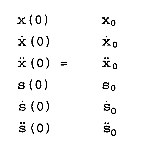
Um den Sollabstand zu erreichen, muß daher der durch den
obigen Sechservektor definierte Fahrzustand in einen Fahrzustand
übergehen, der durch den folgenden Sechservektor
definiert ist:
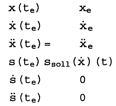
Der Übergang muß so ablaufen, daß das Integral in der Gleichung 90/1 minimal wird. Das bedeutet im einzelnen, daß das Quadrat des Rucks minimiert wird. Durch die Quadrierung der zu integrierenden Funktion ist die Aufgabe unabhängig davon geworden, ob es sich bei der Übergangsbeschleunigung um eine positive oder negative Beschleunigung handelt. Das heißt, daß, wenn eine Lösung dieses Problems mit der Randbedingung, die durch die Sechservektoren von oben gegeben ist, gefunden wird, so ist damit das Problem sowohl beim Bremsen als auch beim Schnellerwerden des Fahrzeugs gelöst. Ergänzend muß hierbei noch beachtet werden, daß die Integrationsgrenzen für die Berechnung des Integrals festgelegt werden. Es ist jedoch möglich, daß diese Integrationsgrenzen laufend an den momentanen Fahrzustand angepaßt werden. Mit anderen Worten, praktisch kann die Übergangszeit t frei gewählt werden. The transition must be such that the integral in the equation 90/1 becomes minimal. Specifically, that means that Square of the rucks is minimized. By squaring the the function to be integrated is independent of this whether the transition acceleration is a positive or negative acceleration. The means that if a solution to this problem with the constraint, given by the six servectors from above is found, so the problem with both Braking as well as when the vehicle gets faster. In addition, it must also be noted that the limits of integration for the calculation of the integral become. However, it is possible that these limits of integration be continuously adapted to the current driving condition. In other words, the transition time t can be practically free to get voted.
Bei der Durchführung der Berechnung ergibt sich zunächst
die Schwierigkeit, daß zum Zeitpunkt t=0 nicht bekannt ist,
wie sich das vorausfahrende Fahrzeug für t>0 bewegt. Seine
Bewegung muß daher extrapoliert werden. Dazu wird die Bewegung
in eine Tälerreihe entwickelt, die nach der zweiten
Ordnung abgebrochen wird, so daß sich für die Bewegung
x(t) + s(t) ergibt
![]()
![]()
Durch mehrmaliges Differenzieren nach der Zeit geht die
Gleichung 7/4 in die Gleichung
![]()

![]()
Dabei gelten die Randbedingungen


Für die absolute Beschleunigung ![]()

![]()
Wie oben bereits beschrieben, ist dies die Vorgehensweise zum Bestimmen der optimalen Beschleunigungsfunktion, wenn aus einem Anfangszustand mit vorgegebenem Abstand, vorgegebener Relativgeschwindigkeit und vorgegebener Relativbeschleunigung sowie vorgegebener Geschwindigkeit und vorgegebener Beschleunigung des Fahrzeugs übergegangen werden soll in einen Endzustand mit einem vorgegebenen Sollabstand zum vorausfahrenden Fahrzeug. Dies ist jedoch ein spezielles Problem, dessen mathematische Behandlung hier beispielsweise wiedergegeben wurde. Es können auch andere Übergangsbedingungen gestellt werden, wie z.B. der Übergang von einer momentanen Geschwindigkeit in eine Sollgeschwindigkeit oder Sollrelativgeschwindigkeit und ein Übergang zwischen einer momentanen Beschleunigung und einer Sollrelativbeschleunigung oder Sollbeschleunigung, deren Berechnung jeweils im wesentlichen nach den gleichen Prinzipien wie oben beschrieben erfolgt.As already described above, this is the procedure to determine the optimal acceleration function if from an initial state with a predetermined distance, more predetermined Relative speed and predetermined relative acceleration as well as predetermined speed and predetermined Acceleration of the vehicle can be transferred should be in a final state with a predetermined target distance to the vehicle in front. However, this is a special one Problem, its mathematical treatment here, for example was reproduced. There may be other transition conditions such as the transition from a current speed to a target speed or target relative speed and a transition between an instantaneous acceleration and a target relative acceleration or target acceleration, their calculation essentially according to the same principles as described above.
Das für alle Übergangsbedingungen gleiche erfindungsgemäße Verfahren ist in Fig. 30 dargestellt. Wird die Ermittlung einer optimalen Beschleunigungsfunktion für den Übergang von einem Istzustand in einen Sollzustand gewünscht, so wird das Verfahren damit gestartet (Schritt 7-S1), daß ein hoher Wert in einen Speicher geschrieben wird. Dieser Wert in dem Speicher stellt das Integral, das zu minimieren ist, einer - in Schritt 7-S1 - fiktiven Funktion dar, mit dem die in den folgenden Schritten ausgewählten Funktionen verglichen werden.The same according to the invention for all transition conditions The method is shown in FIG. 30. Will the investigation an optimal acceleration function for the transition desired from an actual state to a target state, so the method is started (step 7-S1) that a high value is written into a memory. This value in the memory represents the integral that is to be minimized is a - in step 7-S1 - fictitious function with which the functions selected in the following steps become.
Als nächstes wird in Schritt 7-S2 eine Funktion aus einem Funktionsraum ausgewählt, die im folgenden verarbeitet und verglichen werden soll mit der obigen fiktiven Funktion. Dabei kann im einfachsten Fall der Speicher eine Anzahl von Nullstellen von Polynomen ersten Grades enthalten, wobei die gewünschte Funktion dann durch Multiplikation der mehreren Polynome ersten Grades entsteht, je nach gewünschter höchster Potenz der Funktion. Daneben kann der Speicher auch exponentielle Funktionen in Form ihrer Abklingkoeffizienten beinhalten. Diese Techniken sind dem Fachmann bekannt und brauchen hier daher nicht weiter erläutert zu werden.Next, in step 7-S2, a function becomes one Functional space selected, processed below and to be compared with the above fictional function. In the simplest case, the memory can be a number of Contain zeros of first degree polynomials, where then the desired function by multiplying the several First degree polynomials arise depending on the desired one highest potency of the function. In addition, the memory also exponential functions in the form of their decay coefficients include. These techniques are known to the person skilled in the art and therefore need no further explanation here become.
Bei jeder Auswahl einer Funktion aus dem Funktionsraum wird gleichzeitig ein Laufparameter n inkrementiert.With each selection of a function from the functional space simultaneously increments a running parameter n.
Im nächsten Schritt 7-S3 wird die ausgewählte Funktion nach der Zeit differenziert und anschließend quadriert.In the next step 7-S3, the selected function is after time differentiated and then squared.
In Schritt 7-S4 wird schließlich die Funktion zwischen den
Grenzen 0 und te, d.h. dem Ende der Übergangsphase, integriert.
Hierbei ist te zunächst ein fester Wert. Dieser kann
jedoch je nach Bedarf im Laufe des Verfahrens an die jeweilige
Sollgeschwindigkeit und/oder den jeweiligen Sollabstand
und/oder die Absolutgeschwindigkeit und/oder den momentanen
Abstand angepaßt werden.In step 7-S4, the function between the
Im Schritt 7-S5 wird der Wert dieses Integrals mit dem Wert im Speicher aus Schritt S1 verglichen. Ist der Wert des Integrals kleiner als der Wert, der in dem Speicher steht, so wird das Verfahren mit Schritt 7-S7 fortgesetzt, bei dem die Funktion in Form ihrer Parameter in einem Funktionsspeicher abgespeichert wird. Dieser Funktionsspeicher ist ähnlich dem Funktionsraum in Schritt 7-S2 aufgebaut, nur daß dieser Speicher nur für eine Funktion eingerichtet ist. Nach diesem Schritt 7-S7 wird geprüft, ob der Laufparameter einem vorgegebenen Wert gleicht, der die obere Grenze der zu testenden Funktionen darstellt. Dieser Vergleich findet im Schritt S6 statt.In step 7-S5, the value of this integral becomes the value compared in the memory from step S1. Is the value of the integral less than the value that is in the memory, so the method continues with step 7-S7, in which the function in the form of its parameters in a function memory is saved. This functional memory is built similar to the functional space in step 7-S2, only that this memory is only set up for one function. After this step 7-S7 it is checked whether the running parameter a predetermined value equal to the upper limit of the functions to be tested. This comparison takes place in step S6.
Wird in dem Schritt 7-S5 beim Vergleich des unmittelbar vorher evaluierten Integrals mit dem im Speicher abgelegten Wert festgestellt, daß der im Speicher abgelegte Wert kleiner als der Integralwert ist, so fährt das Verfahren ebenfalls unmittelbar mit Schritt 7-S6 fort, unter Umgehung von Schritt 7-S7.Is in step 7-S5 when comparing the immediate previously evaluated integrals with those stored in memory Value determined that the value stored in the memory is smaller than the integral value, the method also runs proceed immediately to step 7-S6, bypassing Step 7-S7.
Wird im Schritt 7-S6 festgestellt, daß der Laufparameter n noch nicht den Maximalwert nmax erreicht hat, so springt das Verfahren zu Schritt 7-S2 zurück, und es wird eine neue Funktion aus dem Funktionsraum unter Inkrementierung des Laufparameters n ausgewählt. Findet man jedoch, daß der Laufparameter n bereits dem Maximalwert nmax gleicht, so wird die in dem Funktionsspeicher abgelegte Funktion in Schritt 7-S8 als Ergebnis ausgegeben. In Schritt 7-S9, der dem Schritt 7-S8 folgt, endet der Verfahrensablauf.If it is determined in step 7-S6 that the running parameter n has not yet reached the maximum value n max , the method jumps back to step 7-S2 and a new function is selected from the functional space by incrementing the running parameter n. If, however, it is found that the running parameter n is already equal to the maximum value n max , the function stored in the function memory is output as a result in step 7-S8. The process flow ends in step 7-S9, which follows step 7-S8.
Hat man nach der Durchführung des erfindungsgemäßen Verfahrens
einen mathematischen Ausdruck für die optimale Beschleunigungsfunktion
erhalten, die dann z.B. ein Polynom
dritten Grades darstellt, wobei die Koeffizienten des Polynoms
parametrisch von der vorgegebenen Übergangszeit te zum
Erreichen des Sollzustandes und/oder vom momentanen Sollabstand
und/oder von der momentanen Relativgeschwindigkeit
und/oder der momentanen Relativbeschleunigung und/oder der
momentanen Absolutgeschwindigkeit und/oder der momentanen
Absolutbeschleunigung abhängen. Mit "momentan" ist in diesem
Zusammenhang der Beginn der Übergangsphase gemeint.
Beim Zugrundelegen eines solchen Polynoms dritten Grades,
wie es in der Gleichung 7/9 dargestellt ist, kann bei der
digitalen Verarbeitung für einen zeitdiskreten Fahrzeug-Längsregler
die unabhängige Größe t gleich der Abtastzeit
gesetzt werden, so daß jeweils der optimale Beschleunigungswert
für den kommenden Abtastzeitpunkt erhalten wird.
Will man lineare Filter zur Bestimmung der optimalen Beschleunigungsänderung
verwenden, so erhält man dies für einen
kontinuierlichen Fahrzeug-Längsregler, indem man die
Gleichung 7/9 durch eine Reihenentwicklung ersetzt und diese
nach dem linearen Term abbricht. After performing the method according to the invention, has a mathematical expression for the optimal acceleration function been obtained which then represents, for example, a third degree polynomial, the coefficients of the polynomial being parametric from the predetermined transition time t e to reaching the desired state and / or from the current desired distance and / or depend on the current relative speed and / or the current relative acceleration and / or the current absolute speed and / or the current absolute acceleration. In this context, “currently” means the beginning of the transition phase. On the basis of such a third-degree polynomial, as shown in
Die erfindungsgemäße Vorrichtung für die Durchführung des obigen Verfahrens umfaßt einen Speicher zum Abspeichern eines numerischen Wertes, der das Integral einer Funktion darstellt, sowie mehrere zu einem Funktionsraum zusammengefaßte Funktionsspeicher, in denen im voraus die Funktionen abgespeichert sind, unter denen die Übergangsfunktion gefunden werden soll, und schließlich einem einzelnen Funktionsspeicher, in dem die Funktion abgespeichert ist, die das Variationsproblem löst. Außerdem umfaßt die Vorrichtung ein Differenzierglied zum Differenzieren einer ausgewählten Funktion, dessen Ausgang mit dem Eingang eines Quadriergliedes zum Quadrieren der differenzierten Funktion verbunden ist. Dieses Quadrierglied multipliziert die Funktion mit sich selbst und gibt sie anschließend an den Eingang eines Integrators aus. Dieser Integrator bildet das Integral von dem Eingangssignal, wobei die untere Integrationsgrenze im allgemeinen mit dem Start des Verfahrensablaufs zusammenfällt, die aber auch frei gewählt werden kann durch den Fahrer z.B., und die obere Integrationsgrenze te durch den Fahrer vorgegeben wird. Schließlich umfaßt die erfindungsgemäße Steuerungsvorrichtung einen Vergleicher zum Vergleichen des Ausgangswertes des Integrators mit dem in dem Speicher abgelegten numerischen Wert und außerdem zum Ausgeben der gefundenen optimalen Beschleunigungsfunktion.The device according to the invention for carrying out the above method comprises a memory for storing a numerical value, which represents the integral of a function, and several function memories combined into a functional space, in which the functions under which the transition function is to be found are stored beforehand, and finally a single function memory in which the function that solves the variation problem is stored. In addition, the device comprises a differentiating element for differentiating a selected function, the output of which is connected to the input of a square element for squaring the differentiated function. This square element multiplies the function by itself and then outputs it to the input of an integrator. This integrator forms the integral of the input signal, the lower integration limit generally coinciding with the start of the method sequence, but which can also be freely selected by the driver, for example, and the upper integration limit t e is specified by the driver. Finally, the control device according to the invention comprises a comparator for comparing the output value of the integrator with the numerical value stored in the memory and also for outputting the optimal acceleration function found.
Ein weiterer Aspekt der Erfindung betrifft ein Verfahren zur Abstandsregelung mit virtuellen Federn und Dämpfern, also mit künstlich erzeugter Dynamik beim Vorgang des Einregeins eines Abstandes zu einem vorausfahrenden Fahrzeug, sowie eine Vorrichtung zur Durchführung dieses Verfahrens.Another aspect of the invention relates to a method for distance control with virtual springs and dampers, thus with artificially generated dynamics in the process of raining a distance to a vehicle in front, and an apparatus for performing this method.
Es ist allgemein bekannt, den Sollabstand zu einem vorausfahrenden
Fahrzeug in Abhängigkeit von der momentanen eigenen
Geschwindigkeit zu bestimmen. Außerdem kann der Sollabstand
zu dem vorausfahrenden Fahrzeug auch zusätzlich in
Abhängigkeit von der Relativgeschwindigkeit der beiden
Fahrzeuge zueinander ermittelt werden. Dazu wird die eigene
Fahrgeschwindigkeit und der Abstand zu dem vorausfahrenden
Fahrzeug erfaßt. Ein solches System ist z.B. aus DE 43 12
595 bekannt. Das dort beschriebene Sicherheitssystem umfaßt
einen Abstandssensor zur Bestimmung der Entfernung vorausfahrender
Fahrzeuge und einen programmgesteuerten Rechner
zur Verarbeitung der Signale vom Abstandssensor und Ausgabe
entsprechender Steuerbefehle. Der Ultraschall-Abstandssensor
arbeitet nach dem Laufzeitprinzip. Der Rechner
differenziert den Meßwert vom Abstandssensor nach der
Zeit und aktiviert eine Warneinrichtung bzw. bremst das
Fahrzeug ab, wenn die Relativgeschwindigkeit derart groß
und die Entfernung derart klein wird, daß ohne Bremsvorgang
ein Zusammenstoß unvermeidbar ist. Ein weiteres Beispiel
für ein solches Sicherheitssystem ist aus US 5 165 497 bekannt.It is generally known that the target distance to a vehicle ahead
Vehicle depending on the current own
To determine speed. In addition, the target distance
in addition to the vehicle in front
Dependence on the relative speed of the two
Vehicles are determined to each other. This is your own
Driving speed and the distance to the vehicle in front
Vehicle detected. Such a system is e.g. from DE 43 12
595 known. The security system described there includes
a distance sensor to determine the distance ahead
Vehicles and a program-controlled computer
for processing the signals from the distance sensor and output
corresponding control commands. The ultrasonic distance sensor
works on the runtime principle. The computer
differentiates the measured value from the distance sensor according to the
Time and activates a warning device or brakes it
Vehicle off when the relative speed is so high
and the distance becomes so small that without braking
a collision is inevitable. Another example
for such a security system is known from
Zur Regelung des Abstandes zu einem vorausfahrenden Fahrzeug muß mit Hilfe vom sogenannten E-Gas, also dem elektrisch steuerbaren Motormoment, und einer aktiven Bremse, also einer elektrisch betätigbaren Bremse, das (nachfolgende) Fahrzeug so beschleunigt bzw. abgebremst werden, daß sich ein vorgegebener, von der eigenen Fahrgeschwindigkeit (des nachfolgenden Fahrzeugs) abhängiger Abstand einstellt.To control the distance to a vehicle in front must with the help of the so-called E-gas, i.e. the electric controllable engine torque, and an active brake, an electrically operated brake, the (following) Vehicle is accelerated or braked so that yourself a predetermined one, based on your own driving speed (of the following vehicle) dependent distance.
In der Praxis zeigt sich aber, daß zwischen der Ausgabe der Beschleunigungsvorgabe durch eine Steuerungsvorrichtung und dem tatsächlichen Erreichen des Beschleunigungswertes durch das Fahrzeug eine bisweilen erhebliche Zeitspanne vergeht. Diese sogenannte Totzeit führt bei den oben genannten Steuerungen und Systemen nach dem Stand der Technik dazu, daß das Gesamtsystem aus mehreren hintereinanderfahrenden Fahrzeugen zu schwingen beginnt, so daß sich die Schwingungen immer weiter verstärken, bis es schließlich zu einem Absinken wenigstens einzelner Fahrzeuggeschwindigkeiten auf Null oder zum Stau einer Fahrzeugkolonne kommt. In practice, however, it turns out that between the issue of the Acceleration specification by a control device and the actual achievement of the acceleration value the vehicle passes a sometimes considerable period of time. This so-called dead time leads to the controls mentioned above and prior art systems that the entire system consisting of several vehicles driving in series begins to vibrate so that the vibrations keep increasing until it finally drops at least individual vehicle speeds to zero or comes to a traffic jam in a convoy.
Aufgabe dieses Aspekts der Erfindung ist es daher, ein Verfahren und eine Vorrichtung anzugeben, mit dem bzw. der unerwünscht starke Geschwindigkeitsänderungen des Fahrzeugs zu vermeiden.The object of this aspect of the invention is therefore a method and to provide a device with which the undesired strong speed changes of the vehicle to avoid.
Diese Aufgabe wird gemäß den Ansprüche 114 und 118 gelöst. Bevorzugte Ausführungsformen des Verfahrens wie der Vorrichtung sind Gegenstand der jeweiligen Unteransprüche.This object is achieved according to claims 114 and 118. Preferred embodiments of the method such as the device are the subject of the respective subclaims.
Bei der Untersuchung des obigen Problems hat der Erfinder erkannt, daß sich die Abstandsregelung zwischen einem vorausfahrenden Fahrzeug und einem nachfolgenden Fahrzeug mit einem Modell aus einer mit Feder und Dämpfer unter Einbeziehung von Reibung gekoppelten Masse beschreiben läßt. Auf dieses Modell beziehen sich die folgenden Erläuterungen.When examining the above problem, the inventor recognized that the distance control between a preceding Vehicle and a following vehicle with a model of one with spring and damper with inclusion mass coupled by friction. On The following explanations refer to this model.
Das Verfahren ist gekennzeichnet durch Ausgeben einer Sollfolgebeschleunigung zum Erreichen eines Sollabstandes Asoll zu einem vorausfahrenden Fahrzeug, die von dem momentanen Abstand s, der Relativgeschwindigkeit vrel und der Absolutgeschwindigkeit vabs abghängt. Mit dem momentanen Abstand s ist hier der Abstand zu der Zeit gemeint, zu der die Ausgabe der Sollfolgebeschleunigung aFsoll erfolgt. Mit dieser Abhängigkeit der Sollfolgebeschleunigung aFsoll von dem Abstand s, der Relativgeschwindigkeit vrel und der eigenen oder Absolutgeschwindigkeit vabs wird gegenüber dem Stand der Technik in die Bestimmung der Sollfolgebeschleunigung ein zusätzlicher Term eingeführt, der modellhaft betrachtet der Reibung des Fahrzeuges auf der Fahrbahn entspricht. Die Tot- bzw. Reaktionszeiten der Steuerungen und Aktoren des Fahrzeuges können durch eine Masse, die Regelung auf konstanten Abstand zwischen den Fahrzeugen durch eine Feder modelliert werden. The method is characterized by outputting a target sequence acceleration to achieve a desired distance A is a preceding vehicle, the abghängt s, the relative velocity v rel and the absolute velocity v abs of the instantaneous distance. The instantaneous distance s here means the distance to the time at which the output of the target follow-on acceleration a Fsoll takes place. With this dependency of the target follow-on acceleration a Fsoll on the distance s, the relative speed v rel and the own or absolute speed v abs , an additional term is introduced compared to the prior art in the determination of the target follow-on acceleration, which corresponds to the model's friction of the vehicle on the road , The dead times or reaction times of the controls and actuators of the vehicle can be modeled by means of a mass, the regulation at a constant distance between the vehicles by means of a spring.
In einer bevorzugten Ausführungsform ist die Sollfolgebeschleunigung
aFsoll die Summe aus einer ersten Komponente f,
die vom momentanen Abstand s zu einem vorausfahrenden Fahrzeug
abhängt, und einer zweiten Komponente g, die von der
Relativgeschwindigkeit vrel gegenüber einem vorausfahrenden
Fahrzeug abhängt. Die Abhängigkeiten sind dabei ihrerseits
eine Funktion der Absolutgeschwindigkeit vabs, so daß sich
formelmäßig dies darstellen läßt als
In einer besonders bevorzugten Ausführungsfunktion werden dabei die Funktionswerte f und g addiert.In a particularly preferred execution function the function values f and g are added.
In einer weiteren bevorzugten Ausführungsform des Verfahrens
wird die Sollfolgebeschleunigung aFsoll als Summe aus
drei Komponenten bestimmt. Dabei ist der erste Summand oder
die erste Komponente ein vom Abstand s abhängiger Term.
Insbesondere kann dieser abstandsabhängige Term proportional
zu der zweiten Ableitung des Abstandes nach der Zeit
sein, er kann aber auch direkt vom Abstand abhängen. Der
zweite Summand oder die zweite Komponente hängt in dieser
Ausführungsform von der Relativgeschwindigkeit vrel ab. Insbesondere
ist der zweite Summand proportional zu der Relativgeschwindigkeit.
Der dritte Summand schließlich hängt
von der Absolutgeschwindigkeit, also der Geschwindigkeit
des nachfolgenden Fahrzeuges, also des Fahrzeuges ab, in
dem das erfindungsgemäße System eingebaut ist. Auch hier
ist der dritte Summand insbesondere proportional zu der Absolutgeschwindigkeit,
so daß sich als eine spezielle Ausführungsform
eine Sollfolgebeschleunigung in der Form
Die Wichtungsfaktoren können konstant sein. Dies hat jedoch
den Nachteil, daß die zusätzlichen Reibungsterme auf Dauer
dazu führen, daß sich der Abstand zwischen den Fahrzeugen
unerwünscht vergrößert. In einer bevorzugten Ausführungsform
des erfindungsgemäßen Verfahrens werden daher variable
Koeffizienten bei der Evaluierung der Sollfolgebeschleunigung
verwendet. Diese variablen Koeffizienten hängen dann
bevorzugt von der Relativgeschwindigkeit vrel ab, so daß
gilt
In einer einfachsten Version ist die Abhängigkeit der Koeffizienten von der Relativgeschwindigkeit dabei linear. Es kann aber auch je nach Koeffizient eine unterschiedliche Abhängigkeit der Koefizienten von der Relativgeschwindigkeit gewählt werden. Dies ist insbesondere dann sinnvoll, wenn die Wichtung der einzelnen Komponenten oder Summanden in der obigen Gleichung (8/2) vom Fahrzustand abhängen sollen. Insbesondere läßt sich so erreichen, daß dann bei kleinen Differenzgeschwindigkeiten der "Dämpfer" zwischen den beiden Fahrzeugen und bei großen Differenzgeschwindigkeiten der "Dämpfer" zwischen dem Fahrzeug und der Fahrbahn für die Sollfolgebeschleunigung bestimmend wird. Der Übergang zwischen den beiden Fällen kann darüber hinaus bei geschickter Wahl der Abhängigkeit der Koeffizienten von der Relativgeschwindigkeit gleitend gestaltet werden.The simplest version is the dependency of the coefficients linear from the relative speed. It can also vary depending on the coefficient Dependence of the coefficients on the relative speed to get voted. This is particularly useful if if the weighting of the individual components or summands in the above equation (8/2) depend on the driving condition. In particular, it can be achieved that at small differential speeds of the "damper" between the two vehicles and at high differential speeds the "damper" between the vehicle and the road is determining for the target follow-up acceleration. The transition between the two cases can moreover when skillful Choice of the dependence of the coefficients on the Relative speed can be designed smoothly.
Durch die variablen Koeffizienten ist der Zusammenhang zwischen Sollfolgebeschleunigung und der Relativ- bzw. Absolutgeschwindigkeit nicht mehr linear. Dies gilt bereits für die sehr einfache Gleichung (8/2). Neben der Darstellung der Sollfolgebeschleunigung als Summe lassen sich aber selbstverständlich auch kompliziertere Funktionen finden, die zur Erzielung spezieller Effekte andere Reibgesetze zugrunde legen, was nichtlinearen Federn und Dämpfern entspricht.Due to the variable coefficients, the relationship between Target following acceleration and the relative or absolute speed no longer linear. This already applies to the very simple equation (8/2). In addition to the representation the target follow-up acceleration as a sum can, however of course find more complicated functions, other friction laws to achieve special effects based on what corresponds to non-linear springs and dampers.
Das Verfahren wurde numerisch simuliert und zeigte das erwartete Verhalten: die durch die Totzeiten zwischen Ausgabe eines Sollbeschleunigungswertes, der ohne virtuelle Federn und Massen berechnet wurde, und dem Erreichen der gewünschten Beschleunigung angefachten Schwingungen einer Fahrzeugkolonne wurden mit dem erfindungsgemäßen Verfahren unterdrückt, es kam nicht mehr zu bleibenden Regelabweichungen.The procedure was numerically simulated and showed the expected Behavior: caused by the dead times between issue a target acceleration value without virtual springs and masses was calculated, and reaching the desired Acceleration of fanned vibrations in a column of vehicles were suppressed using the method according to the invention, there were no longer any regular deviations.
Im folgenden wird ein Ausführungsbeispiel des erfindungsgemäßen
Verfahrens anhand der Zeichnungen beschrieben. Dabei
ist in
Fig. 31 zeigt zwei hintereinanderfahrende Fahrzeuge 8-1 und 8-2, von denen das hintere Fahrzeug 8-1 dasjenige ist, in welchem die erfindungsgemäße Steuerung eingebaut ist. Die beiden Fahrzeuge sind durch eine virtuelle Feder 8-3 und einen virtuellen Dämpfer 8-4 miteinander verbunden. Diese beiden virtuellen Kopplungsglieder sind einstellbar, so daß sich gewünschter oder Sollabstand zwischen den beiden Fahrzeugen ergibt, der sich aus einem von der Absolutgeschwindigkeit abhängigen Term und einem sogenannten "offset"-Term Aoffset zusammensetzt. Der von der Absolutgeschwindigkeit abhängige Term läßt sich dabei als Produkt aus, einer Zeit und der Absolutgeschwindigkeit vabs darstellen. Der Zeitfaktor in dem Produkt ist dabei die Zeit, die bei der momentanen Absolutgeschwindigkeit vergehen würde, bis das (nachfahrenden) Fahrzeug 8-1 auf das stehende "vorausfahrende" Fahrzeug auffahren würde (time to collision, Tcol). Der Feder wirkt der Dämpfer 8-4 in gewisser Weise entgegen und verhindert so zu große Ausschläge bzw. Schwingungsamplituden des Systems aus zwei aufeinander folgenden Fahrzeugen.31 shows two vehicles 8-1 and 8-2 traveling in series, of which the rear vehicle 8-1 is the one in which the control according to the invention is installed. The two vehicles are connected to each other by a virtual spring 8-3 and a virtual damper 8-4. These two virtual coupling elements are adjustable so that the desired or desired distance between the two vehicles results, which is composed of a term dependent on the absolute speed and a so-called "offset" term A offset . The term dependent on the absolute speed can be represented as a product of a time and the absolute speed v abs . The time factor in the product is the time that would pass at the current absolute speed until the (following) vehicle 8-1 would collide with the stationary “preceding” vehicle (time to collision, T col ). The spring 8-4 acts in a certain way against the spring and thus prevents excessive deflections or vibration amplitudes of the system from two successive vehicles.
Der in Fig. 31 dargestellte Sachverhalt gibt die Situation im statischen Fall korrekt wieder. Beim Übergang zu dem zeitlich veränderlichen Fall müssen jedoch die zeitliche Entwicklung der Fahrgrößen mit berücksichtigt werden. Der Aufbau der erfindungsgemäßen Steuerung, die hierfür einsetzbar ist, ist in Fig. 32 gezeigt.The situation shown in Fig. 31 gives the situation in the static case correctly again. When transitioning to that time-changing case, however, must be the temporal Development of the driving variables are taken into account. The Structure of the control according to the invention, which can be used for this is shown in FIG. 32.
Ein Abstandssensor 8-5 gibt Signale aus, die dem momentanen
Abstand d des Fahrzeugs 8-1 von einem vorausfahrenden Fahrzeug
8-2 entsprechen. Diese Signale können aus der Laufzeit
von z. B. Ultraschallpulsen abgeleitet werden, oder sie
können mittels Triangulationsmethode bei Dauerstrichsignalen
gewonnen werden. Mit dem fortlaufend gemessenen Abstand
ist auch seine Änderung über die Zeit, d. h. seine zeitliche
Ableitung vrel bekannt. Gleichzeitig wird vom Geschwindigkeitswählschalter
die momentane Geschwindigkeit des
Fahrzeuges 8-1 und damit ein Mindestabstand vorgegeben, den
das Fahrzeug 8-1 von einem vorausfahrenden Fahrzeug 8-2
einzuhalten hat. Dieser Mindestabstand beträgt wie bereits
in Zusammenhang mit Fig. 31 beschrieben
Der von dem Geschwindigkeitswählschalter 8-6 ausgegebene Mindestabstand d wird von dem vom Abstandssensor 8-5 ausgegebenen momentanen Abstand in einem Subtrahierer 8-7 abgezogen. Das Differenzsignal der beiden Abstände aus dem Subtrahierer 8-7 ist die Eingangsgröße eines Federekennliniengliedes 8-9. In diesem Federkennlinienglied 8-9 wird entsprechend der Eingangsgröße ein erster Beschleunigungswert erzeugt. Der Zusammenhang zwischen Eingangsgröße und Ausgangsgröße, also erstem Beschleunigungswert ist hierbei in der Regel nichtlinear.The one output from the speed selector switch 8-6 Minimum distance d is given by the distance sensor 8-5 subtractor 8-7. The difference signal of the two distances from the subtractor 8-7 is the input variable of a spring characteristic element 8-9. In this spring characteristic element 8-9 a first acceleration value corresponding to the input variable generated. The relationship between input variable and The output variable, i.e. the first acceleration value, is here usually non-linear.
Neben der Bestimmung eines ersten Beschleunigungwertes aus dem Federkennlinienglied 8-9 wird das nach der Zeit differenzierte Abstandssignal (das insbesondere aus einer Dopplerverschiebungsmessung stammen kann) von dem Abstandssensor 8-5 zur Bestimmung eines zweiten Beschleunigungswertes herangezogen. Dabei wird das zeitlich abgeleitete Signal als Eingangsgröße eines Dämpfungskennliniengliedes 8-8 verwendet, das einen zweiten Beschleunigungswert ausgibt. Auch hier ist der Zusammenhang zwischen Eingangsgröße und Ausgangswert in der Regel nichtlinear.In addition to determining a first acceleration value the spring characteristic element 8-9 is differentiated according to time Distance signal (in particular from a Doppler shift measurement can originate) from the distance sensor 8-5 to determine a second acceleration value used. The time-derived signal used as the input variable of a damping characteristic element 8-8, that outputs a second acceleration value. Also here is the relationship between input variable and output value usually non-linear.
In beiden Kennliniengliedern 8-8 und 8-9 werden bei dem erfindungsgemäßen Verfahren dabei von der Absloutgeschwindigkeit abhängige Kennlinien verwendet; d. h. die in jedem Kennlinienglied gespeicherte Kennlinien hängt parametrisch von der momentanen eigenen Absolutgeschwindigkeit vabs ab.In both characteristic curve elements 8-8 and 8-9, characteristic curves dependent on the absout speed are used in the method according to the invention; that is, the characteristic curve stored in each characteristic element depends parametrically on the current own absolute speed v abs .
Die beiden Beschleunigungswerte werden in einem Addierer 8-10 addiert und anschließend gefiltert und in ihrer maximalen Amplitude begrenzt durch einen Filter 8-11. Dieser gefilterte und begrenzte Beschleunigungswert entspricht der Sollfolgebeschleunigung.The two acceleration values are in an adder 8-10 added and then filtered and at their maximum Amplitude limited by a filter 8-11. This filtered and limited acceleration value corresponds to the Should result acceleration.
In einer anderen Ausführungsform der erfindungsgemäßen Steuerungsvorrichtung, die in Fig. 33 gezeigt ist, werden die Kennlinienglieder 8-8 und 8-9 zusammengefaßt zu einem Kennfeldglied 8-12, so daß mit Abstand und Relativgeschwindigkeit von dem Abstandssensor 8-5 als Eingangsgrößen aus einem quasi dreidimensionalen Kennfeld ein entsprechender Wert für den Beschleunigungswert abgelesen werden kann. Auch hier hängt die Schar der Kennfelder parametrisch von der momentanen Absolutgeschwindigkeit vabs des Fahrzeuges ab. Die Ausführungsform nach Fig. 33 hat den Vorteil, daß damit der Addierer 8-10 eingespart werden kann.In another embodiment of the control device according to the invention, which is shown in Fig. 33, the characteristic elements 8-8 and 8-9 are combined to form a characteristic element 8-12, so that with distance and relative speed from the distance sensor 8-5 as input variables from one quasi three-dimensional map, a corresponding value for the acceleration value can be read. Here too, the family of characteristic maps depends parametrically on the current absolute speed v abs of the vehicle. The embodiment according to FIG. 33 has the advantage that the adder 8-10 can be saved.
In Fig. 34 ist der Verlauf von wichtigen Fahrgrößen während der Steuerungsphase dargestellt. In Fig. 34a ist der Verlauf des Abstandes des Fahrzeuges 8-1 von dem vorausfahrenden Fahrzeug 8-2 über die Zeit aufgetragen. Zum Zeitpunkt t = 0 beträgt dieser Abstand z. B. 200 m. Der Sollabstand betrage zunächst 10 m. Dieser Sollabstand muß aber zeitlich nicht konstant sein, er hängt wie bereits beschrieben wesentlich von der augenblicklichen Fahrsituation ab, insbesondere von der Geschwindigkeit des vorausfahrenden Fahrzeuges, von der eigenen Absolutgeschwindigkeit etc.34 shows the course of important driving variables during the control phase. 34a is the course the distance of the vehicle 8-1 from the vehicle in front Vehicle 8-2 plotted over time. At the time t = 0 this distance is z. B. 200 m. The target distance initially amount to 10 m. This target distance must be timed not constant, it depends essentially as already described depending on the current driving situation, in particular the speed of the vehicle in front, your own absolute speed etc.
Um eine möglichst zügige Annäherung der beiden Fahrzeuge auf den Sollabstand zu erreichen, wie er am rechten Ende der graphischen Darstellung des zeitlichen Verlaufs des Abstandes und des Sollabstandes erreicht ist, muß die Geschwindigkeit eingestellt werden, wie sie in Fig. 34b gezeigt ist. Dabei wird angenommen, daß das vorausfahrende Fahrzeug 8-2 mit einer konstanten Geschwindigkeit von 50 km/h fährt. Wenn nun das Fahrzeug 8-1 beschleunigt wird, um den Abstand zu dem vorausfahrenden Fahrzeug 8-1 zu verringern, so ändert sich wie in Teil a der Fig. 34 gezeigt der Sollabstand in Abhängigkeit von der Absolutgeschwindigkeit. Da die Geschwindigkeit immer wieder je nach momentanem Abstand vom vorausfahrenden Fahrzeug 8-2 nachgeführt wird, kommt es zu kleinen Schwankungen der Geschwindigkeitskurve, die etwas "höherfrequent" sind. Diese höherfrequenten Anteile in der Geschwindigkeit finden sich dann in dem Beschleunigungssignal in Fig. 34c wieder. Dort sind sie deutlich ausgeprägt und zeigen die Reaktion und die Nachführung der Sollfolgebeschleunigung durch das erfindungsgemäße System und Verfahren.To bring the two vehicles closer together as quickly as possible to reach the target distance as he is at the right end the graphical representation of the time course of the distance and the target distance is reached, the speed can be set as shown in Fig. 34b is. It is assumed that the vehicle in front Vehicle 8-2 at a constant speed of 50 km / h drives. Now if the vehicle 8-1 is accelerated to reduce the distance to the vehicle in front 8-1, so changes as shown in part a of FIG Target distance depending on the absolute speed. Because the speed always depends on the current distance is tracked by the vehicle 8-2 in front, there are small fluctuations in the speed curve, which are a bit "higher frequency". These higher frequency parts in speed are then found in the acceleration signal in Fig. 34c again. They are clear there pronounced and show the reaction and tracking the target follow-up acceleration by the system according to the invention and procedures.
Ein weiterer Aspekt der Erfindung betrifft ein Bedienkonzept für einen Abstandsregeltempomat und insbesondere ein Verfahren zum Einstellen eines Sollabstands zu einem vorausfahrenden Fahrzeug durch einen Abstandsregler, wobei der Fahrer den eingeregelten Abstand modifizieren kann. Außerdem betrifft dieser Aspekt der Erfindung eine Vorrichtung zur Durchführung des Verfahrens.Another aspect of the invention relates to an operating concept for a cruise control and in particular a Method for setting a target distance to a preceding one Vehicle through a distance controller, being the driver can modify the set distance. Moreover this aspect of the invention relates to a device to carry out the procedure.
Bei der Einführung der automatischen Regelung des Abstandes eines Fahrzeuges zum vorausfahrenden Fahrzeug stellt sich die Frage nach dem richtigen Abstand. Es gibt die Faustregel "halber Tacho" und den gesetzlich vorgeschriebenen Sicherheitsabstand von "einem Viertel der gefahrenen km/h in Metern". In der täglichen Fahrpraxis werden diese Werte durch zu dichtes Auffahren regelmäßig unterschritten.At the introduction of automatic distance control of a vehicle turns to the vehicle in front the question of the correct distance. There is a rule of thumb "Half speedometer" and the legally required safety distance from "a quarter of the km / h driven in Meters ". In everyday driving practice these values regularly falling below due to excessive opening.
Bei automatischen Abstandsreglern wird der Sollabstand zu einem vorausfahrenden Fahrzeug in Abhängigkeit von der momentanen eigenen Geschwindigkeit bestimmt. Zur Abstandsregelung wird ein momentaner Abstand zu dem vorausfahrenden Fahrzeug erfaßt, eine Absolutgeschwindigkeit erfaßt, ein erster Sollabstand aus dem momentanen Abstand und der Absolutgeschwindigkeit betimmt.In the case of automatic distance controllers, the target distance becomes too a preceding vehicle depending on the current one own speed determined. For distance control becomes a current distance to the vehicle in front Vehicle detected, an absolute speed detected, a first target distance from the current distance and the absolute speed betimmt.
Ein solches System ist z.B. aus DE 31 30 873 bekannt. Der dort beschriebene Abstandsregler ist einsetzbar für ein von einem Motor angetriebenes erstes Fahrzeug, das ein in eine Leerlaufstellung für den Motor vorgespanntes Leistungssteuerelement, ein Bremssteuerelement und einen Signalgenerator aufweist. Der Signalgenerator erzeugt zu dem Abstand des vorausfahrenden zweiten Fahrzeugs proportionale erste sowie zweite Steuersignale, die beim Unterschreiten vorbestimmter Abstände das Leistungssteuerelement und das Bremssteuerelement betätigen. Wenn der Abstand ein erstes Maß unterschreitet, drängt das erste Stellglied das Leistungssteuerelement mit zunehmend kleiner werdendem Abstand unter zunehmender Federkraft in Richtung der Leerlaufstellung. Wenn der Abstand ein zweites Maß unterschreitet, das kleiner als das erste Maß ist, und wenn das Leistungselement um ein vorgegebenes Maß in die Leerlaufstellung gedrängt ist, bremst das zweite Stellglied zunehmend das erste Fahrzeug mit zunehmend kleiner werdendem Abstand. Wenn der Abstand ein drittes Maß unterschreitet, das kleiner als das zweite Maß ist, so gibt der Signalgenerator an das zweite Stellglied dritte Steuersignale zur Vollbremsung des ersten Fahrzeuges und an ein drittes Stellglied zur Rückstellung des Leistungssteuerelements in seine Leerlaufstellung und zum Halten in seiner Leerlaufstellung aus.Such a system is e.g. known from DE 31 30 873. The Distance controller described there can be used for one of an engine driven first vehicle that is inserted into a Idle position for the engine preloaded power control element, a brake control element and a signal generator having. The signal generator generates to the distance of the leading second vehicle proportional first as well second control signals that fall below predetermined Clearances the power control and the brake control actuate. If the distance falls below a first dimension, the first actuator urges the power control element as the distance becomes smaller and smaller Spring force in the neutral position. If the distance falls below a second dimension, which is smaller than the first measure is and if the power element is around a the specified dimension is pushed into the idle position, the second actuator increasingly brakes the first vehicle with increasing distance. If the distance falls below a third dimension, which is smaller than the second Dimension is, so the signal generator to the second actuator third control signals for full braking of the first Vehicle and to a third actuator for resetting the power control to its idle position and to stop in its idle position.
Ein weiteres Beispiel für ein solches Verfahren zur Abstandsregelung von Kraftfahrzeugen ist aus DE 44 37 678 bekannt. Bei dem Verfahren wird der Abstand zum vorausfahrenden Kraftfahrzeug durch eine Meßeinheit erfaßt, dieser durch eine Kontrolleinheit ausgewertet und in Abhängigkeit der Auswertung ein geschwindigkeitsabhängiger Sollabstand eingestellt.Another example of such a distance control method of motor vehicles is known from DE 44 37 678. In the process, the distance to the vehicle in front becomes Motor vehicle detected by a measuring unit, this evaluated by a control unit and dependent the evaluation a speed-dependent target distance set.
Jedoch werden diese Regelungen erfahrungsgemäß vom Fahrer ausgeschaltet, wenn der Abstandsregler aufgrund des Verkehrflusses dauernd in die Fahrzeugsteuerung eingreifen müßte und dies zu einem häufigen Abbremsen des Fahrzeuges führte, weil z. B. häufig andere Fahrzeuge vor dem Fahrzeug mit Abstandsregler einscheren. Bei den meisten Abstandsreglern beinhaltet ihr Bedienkonzept bereits die sofortige Abschaltung der Geschwindigkeitsregelung, sobald das Fahrpedal oder das Bremspedal betätigt wird. Schaltet der Fahrer den Abstandsregler aus, so kann es somit trotz eingebautem Abstandsregler zu einem zu dichten Auffahren kommen.However, experience has shown that these regulations are applied by the driver turned off when the distance controller due to traffic flow constantly intervene in the vehicle control should and this to a frequent braking of the vehicle led because z. B. often other vehicles in front of the vehicle Cut in with distance controller. With most distance controllers your operating concept already includes immediate shutdown the cruise control as soon as the accelerator pedal or the brake pedal is operated. Switches the driver the distance controller, so it can despite the built-in Distance controllers come to a too tight opening.
Daher werden variable Abstandsregler untersucht. Für diese noch in der Entwicklung befindlichen Abstandsregler wird zur Zeit mit zusätzlichen Bedienelementen für den Fahrer wie Drehknopf oder Schieber zur Eingabe des Grades der Unterschreitung des Sicherheitsabstandes experimentiert. Diese neuen Bedienelemente haben aber den Nachteil, daß es eben "zusätzliche" Bedienelements sind, deren Funktion der Fahrer erst einmal verstehen muß.Therefore variable distance controllers are examined. For this distance controller still under development currently with additional controls for the driver such as rotary knob or slider for entering the degree of undershoot of the safety distance experimented. This New controls have the disadvantage that it just "Additional" controls are, the function of which Driver must first understand.
Aufgabe dieses Aspekts der Erfindung ist es daher, ein Verfahren und eine Vorrichtung anzugeben, mit dem bzw. der der Fahrer den Sicherheitsabstand unterschreiten kann, ohne den Abstsandsregler ausschalten zu müssen und ohne daß zusätzliche Bedienelemente erforderlich werden.The object of this aspect of the invention is therefore a method and to provide a device with which the Driver can fall below the safety distance without the Distance controller must be switched off and without additional Controls are required.
Diese Aufgabe wird durch die Ansprüche 122 und 126 gelöst. Bevorzugte Ausführungsformen des Verfahrens wie der Vorrichtung sind Gegenstand der jeweiligen Unteransprüche.This object is solved by claims 122 and 126. Preferred embodiments of the method such as the device are the subject of the respective subclaims.
Das Verfahren ist gekennzeichnet durch das Ausgeben eines zweiten Sollabstandes Asoll bei Betätigen eines Fahrpedals. The method is characterized by the output of a second target distance A target when an accelerator pedal is pressed.
Damit wird erreicht, daß der Fahrer den Abstandsregler eingeschaltet lassen kann. Erfindungsgemäß wird also bei eingeschaltetem Abstandsregler der gesetzlich zulässige Abstand eingehalten, solange das Fahrpedal (Gaspedal) des Fahrzeuges sich in seiner Ausgangsstellung befindet. Sobald der Fahrer dagegen das Fahrpedal betätigt, wird der einzuregelnde Sollabstand in Abhängigkeit vom Wert der Pedalbetätigung verkürzt. Dies hat zur Folge, daß der Fahrer nach wie vor die volle Kontrolle über sien Fahrzeug behält und so auch die Verantwortung für ein Unterschreiten des Sicherheitsabstandes behält. Trotzdem kann er die Vorteile der automatischen Abstandsregelung nutzen.This ensures that the driver switches on the distance controller can leave. According to the invention, therefore, when switched on Distance controller the legally permissible distance kept as long as the accelerator pedal (accelerator pedal) of the Vehicle is in its starting position. As soon as the driver, on the other hand, pressing the accelerator pedal becomes the one to be regulated Target distance depending on the value of the pedal actuation shortened. This has the consequence that the driver after remains in full control of your vehicle and thus also the responsibility for falling below the safety distance reserves. Even so, he can take advantage use the automatic distance control.
In einer bevorzugten Ausführungsform werden bei Unterschreiten des Sicherheitsabstandes Warnsignale an den Fahrer ausgegeben, deren Höhe von der Größe der Unterschreitung abhängt. Die Ausgabe der Warnsignale erfolgt dabei akustisch und/oder optisch und/oder haptisch.In a preferred embodiment, falling below the safety distance warning signals to the driver spent, the amount of which falls short of the size depends. The warning signals are output acoustically and / or optically and / or haptically.
Durch die vorgeschlagenen Maßnahmen wird die Bedienbarkeit des erfindungsgemäßen Abstandsreglers besser als die der Abstandsregler nach dem Stand der Technik, da er in allen Fahrsituationen, insbesondere auch bei hohem Verkehrsaufkommen ständig eingeschaltet bleiben kann und nicht wie beim Stand der Technik deaktiviert werden muß, wenn der Fahrer dir Absicht hat, den Sicherheitsabstand zu unterschreiten. Das Verhalten der erfindungsgemäßen Abstandsregelung ist insofern transparent, als die Betätigung des Fahrpedals dazu führt, daß das eigene Fahrzeug trotz eingeschaltetem Abstandsregler wie gewohnt näher an das vorausfahrende Fahrzeug heranfährt und beim Lösen des Fahrpedals wieder zurückfällt. Die Abstandsregelung bleibt stets aktiv und verhindert eine Kollision auch bei verkürztem Sicherheitsabstand. The proposed measures will make it usable of the distance controller according to the invention better than that of Distance controller according to the state of the art, since it is used in all Driving situations, especially when there is a lot of traffic can stay on all the time and not how must be deactivated in the prior art if the Driver intends to stay below the safety distance. The behavior of the distance control according to the invention is transparent in that the operation of the Accelerator pedal leads to the fact that the own vehicle despite being switched on Distance control closer to the one in front as usual Vehicle approaches and when the accelerator pedal is released falls back again. The distance control always remains active and prevents a collision even with a reduced safety distance.
Im folgenden wird ein Ausführungsbeispiel des erfindungsgemäßen Verfahrens anhand der Zeichnungen beschrieben. Dabei ist in Fig. 35 der Flußlaufplan einer Ausführungsform des erfindungsgemäßen Verfahrens dargestellt.The following is an embodiment of the invention Process described with reference to the drawings. there 35 is the flow chart of an embodiment of the represented method according to the invention.
Bei dem Verfahren zum Regeln eines Sollabstandes zu einem vorausfahrenden Fahrzeug nach Fig. 35 wird nach dem Start (Schritt 9-S1), also dem Aktivieren des Abstandsreglers oder der Steuerungsvorrichtung, in dem Schritt 9-S2 der Abstand s zu einem vorausfahrenden Fahrzeug erfaßt. Dies geschieht wie allgemein bekannt mit Hilfe eines Abstandssensors, der beispielsweise auf der Lausfzeitmessung von Ultraschall-, Laser- oder Radarpulsen oder der Triangulation von Laserdauerstrichsignalen beruht.In the method for regulating a target distance to one the preceding vehicle according to Fig. 35 is after the start (Step 9-S1), i.e. activating the distance controller or the control device, in step 9-S2 the distance s recorded for a vehicle in front. this happens as is generally known with the help of a distance sensor, for example on the measurement of the ultrasound Laser or radar pulses or triangulation based on laser continuous wave signals.
Anschließend wird in Schritt 9-S3 eine Absolutgeschwindigkeit vabs des Fahrzeugs erfaßt. Vorzugsweise wird dazu die Referenzgeschwindigkeit eines ABS-Systems übernommen, es kann aber auch jedes andere, die Geschwindigkeit des Fahrzeugs repräsentierende Signal wie z. B. das Tachosignal ausgewertet werden.An absolute speed v abs of the vehicle is then detected in step 9-S3. The reference speed of an ABS system is preferably adopted for this purpose, but it can also be any other signal representing the speed of the vehicle, such as. B. the speedometer signal can be evaluated.
Aus den bis hierher bekannten Größen wird in Schritt 9-S4 ein erster Sollabstand Asoll bestimmt, der von der Absolutgeschwindigkeit vabs abhängt.In step 9-S4, a first target distance A target is determined from the variables known up to this point, which depends on the absolute speed v abs .
Wird in Schritt 9-S5 festgestellt, daß der Fahrer durch Betätigung des Fahrpedals eine Beschleunigungsvorgabe gemacht hat, die zu einer Unterschreitung des ersten Sollabstandes führen würde, so wird diese Fahrervorgabe erfaßt. Dazu kann der Stellwinkel ϕ des Fahrpedals erfaßt werden.In step 9-S5, it is determined that the driver is operating made an acceleration specification of the accelerator pedal has to fall below the first target distance would lead, this driver specification is recorded. This can the setting angle ϕ of the accelerator pedal can be detected.
Mit der Fahrervorgabe wird in Schritt 9-S7 ein neuer, zweiter Sollabstand Asoll' bestimmt und ausgegeben. Dabei kann dieser neue Sollabstand Asoll' von dem Stellwinkel ϕ abhängen, beispielsweise linear oder über eine vorher abgespeicherte Kennlinie. Der zweite Sollabstand wird in Schritt 9-S8 eingestellt.With the driver's selection, in step S7, a new 9-, second nominal distance A is determined 'and output. This new target distance A soll 'can depend on the setting angle ϕ, for example linearly or via a previously stored characteristic curve. The second target distance is set in step 9-S8.
Nach der Bestimmung des neuen Sollabstandes Asoll' springt das Verfahren an die gleiche Stelle wie nach Schritt 9-S5, wo das Verfahren fortgesetzt wird, wenn der Fahrer keine Beschleunigungsvorgabe gemacht hat.After the determination of the new target distance A soll ', the method jumps to the same point as after step 9-S5, where the method is continued if the driver has not made an acceleration specification.
Schließlich überprüft das Verfahren in Schritt 9-S9, ob die Abstandsregelung abgeschaltet werden soll. Wenn dies der Fall ist, so springt die Ausführung des Verfahrens an die Adresse des Schrittes 9-S10, mit dem das Verfahren endet.Finally, the process checks in step 9-S9 whether the Distance control should be switched off. If this is the If so, the execution of the method jumps to the Address of step 9-S10 with which the method ends.
Wird nicht beabsichtigt, das Verfahren zu unterbrechen, so springt das Verfahren zurück zu Schritt 9-S2 und fährt mit der Erfassung des momentanen Abstandes s zu einem vorausfahrenden Fahrzeug fort. Es schließen sich dananch die übrigen Verfahrensschritte an, bis das Fahrzeug sein Ziel erreicht oder die Abstandsregelung deaktiviert wird.If the intention is not to interrupt the process, then the method jumps back to step 9-S2 and moves on the detection of the current distance s to a vehicle in front Vehicle away. The others then close Procedural steps until the vehicle reaches its destination or the distance control is deactivated.
Ein weiterer Aspekt der Erfindung betrifft ein Verfahren zur Kurvengeschwindigkeitsanpassung bei einem Fahrzeug bei der Fahrt durch eine Kurve sowie eine Vorrichtung zur Durchführung dieses Verfahrens.Another aspect of the invention relates to a method for curve speed adjustment in a vehicle driving through a curve and a device for Performing this procedure.
Es ist allgemein bekannt, die Geschwindigkeiten den augenblicklichen Gegebenheiten automatisch anzupassen und damit dem Fahrer bei der Steuerung des Fahrzeugs zu assistieren: routinemäßige Bedienungserfordernisse werden ihm abgenommen. Auf gerader Strecke übernehmen solche Aufgaben z. B. ein Abstandsregler oder ein Tempomat. Diese leiten Beschleunigungs- bzw. Bremsmanöver in Abhängigkeit von der augenblicklichen Verkehrslage automatisch ein und verhindern so zu dichtes Auffahren oder halten eine eingestellte Tempomatgeschwindigkeit unabhängig von Steigungen. It is well known that the speeds are instantaneous Adjust conditions automatically and thus to assist the driver in controlling the vehicle: routine operating requirements are relieved. Such tasks take over on a straight route. B. a distance controller or a cruise control. These guide acceleration or braking maneuvers depending on the automatically prevent and prevent the current traffic situation opening too tight or holding a set one Cruise control speed regardless of inclines.
Zu den Aufgaben einer umfassenden Geschwindigkeitsregelung gehört auch die Absenkung der Geschwindigkeit in der Kurve, wenn diese zu hoch ist und die Gefahr besteht, daß das Fahrzeug aus der Kurve getragen wird oder aber zumindest der Fahrkomfort für die Insassen sinkt.To the tasks of a comprehensive speed control also includes lowering the speed in the curve, if it is too high and there is a risk that Vehicle is carried out of the curve or at least the driving comfort for the occupants decreases.
In der Praxis zeigt sich, daß eine solche einfache Kurvengeschwindigkeitsbegrenzung zwar die Sicherheit erhöht, nicht aber dem Wunsch der Insassen nach komfortabler Fahrweise Rechnung trägt. Häufig möchte man bereits vor der Situation, in der die automatische Regelung aus Sicherheitsgründen die Steuerung des Fahrzeugs beeinflußt, eine angepaßte Fahrweise eingestellt haben (erweiterte Geschwindigkeitsregelung).In practice it turns out that such a simple curve speed limitation while increasing security, but not the occupants' desire for a comfortable driving style Takes into account. Often, before the situation, in which the automatic regulation for safety reasons affects the control of the vehicle, an adapted Have set their driving style (extended cruise control).
Aufgabe dieses Aspekts der Erfindung ist es, ein Verfahren und eine Vorrichtung zur Anpassung der Kurvengeschwindigkeit anzugeben.The object of this aspect of the invention is a method and a curve speed adjustment device specify.
Diese Aufgabe wird durch die Ansprüche 127 und 134 gelöst. Bevorzugte Ausführungsformen des Verfahrens wie der Vorrichtung sind Gegenstand der jeweiligen Unteransprüche.This object is solved by claims 127 and 134. Preferred embodiments of the method such as the device are the subject of the respective subclaims.
Bei dem Verfahren zur automatischen Anpassung der Kurvengeschwindigkeit eines Fahrzeugs wird zunächst eine Absolutgeschwindigkeit des Fahrzeugs ermittelt. Das Verfahren greift dabei auf bereits bekannte Größen zurück und kann unabhängig von aber auch insbesondere zusammen mit einer Abstandsregelung und/oder einer Geschwindigkeitsregelung in einem Fahrzeug installiert und aktiviert werden kann. Dies ist umso vorteilhafter, da alle genannten Systeme teilweise auf dieselben Aktoren und Sensoren zugreifen, wobei die Fahrsituationen, in denen eingegriffen wird, und die beabsichtigten Wirkungen bei den Systemen jedoch unterschiedlich sind. In the process of automatically adjusting the curve speed a vehicle first becomes an absolute speed of the vehicle. The procedure takes effect go back to already known sizes and can be independent but also in particular together with a distance control and / or a speed control in one Vehicle can be installed and activated. This is all the more advantageous since all of the systems mentioned are partly based on access the same actuators and sensors, whereby the driving situations, in which to intervene and the intended ones Effects in the systems, however, are different.
Im folgenden wird unter Längsdynamikregelung sowohl die Geschwindigkeits- als auch eine Abstandsregelung oder jede andere, die Reisegeschwindigkeit des Fahrzeugs beeinflussende Regelung verstanden.In the following, both the speed as well as a distance control or any others that affect the vehicle's cruising speed Understood scheme.
Das erfindungsgemäße Verfahren zur automatischen Anpassung
der Kurvengeschwindigkeit eines Fahrzeugs ist gekennzeichnet
durch das Erfassen einer Querbeschleunigung des Fahrzeugs.
Diese Querbeschleunigung kann entweder direkt mit
einem Beschleunigungssensor gemessen werden oder aus Gierrate
und Fahrzeuggeschwindigkeit ermittelt werden, sofern
keine Querkdrift wenigstens einer Achse des Fahrzeugs vorhanden
ist. Die ermittelte Querbeschleunigung wird mit einer
vorbestimmten Referenzquerbeschleunigung verglichen,
und es wird ein entsprechendes Geschwindigkeitskorrektursignal
ausgegeben. Aufgrund dieses
Geschwindigkeitskorrektursignals wird ein
Beschleunigungszwischenwert bestimmt, so daß eine
Grenzquerbeschleunigung in der Kurve nicht überschritten
wird.
Dies erfolgt, ohne daß der Fahrer aktiv eingreifen muß.
Verläßt das Fahrzeug die Kurve und fährt wieder geradeaus,
so sinkt die Querbeschleunigung auf Null. Ein Regelungseingriff
im Sinne einer Kurvengeschwindigkeitsanpassung ist
dann nicht mehr erforderlich.The method according to the invention for automatically adjusting the cornering speed of a vehicle is characterized by detecting a lateral acceleration of the vehicle. This lateral acceleration can either be measured directly with an acceleration sensor or determined from the yaw rate and vehicle speed, provided there is no transverse drift of at least one axle of the vehicle. The determined lateral acceleration is compared with a predetermined reference lateral acceleration and a corresponding speed correction signal is output. An intermediate acceleration value is determined on the basis of this speed correction signal, so that a transverse limit acceleration in the curve is not exceeded.
This is done without the driver having to actively intervene. If the vehicle leaves the curve and drives straight again, the lateral acceleration drops to zero. A control intervention in the sense of a curve speed adjustment is then no longer necessary.
Die Referenzquerbeschleunigung, mit der die tatsächliche Querbeschleunigung verglichen wird und die der Grenzbeschleunigung entsprechen kann, liegt dabei für ein komfortables Fahren zwischen 2 und 3 m/s2.The reference lateral acceleration with which the actual lateral acceleration is compared and which can correspond to the limit acceleration is between 2 and 3 m / s 2 for comfortable driving.
Die Vorteile des erfindungsgemäßen Verfahrens liegen darin, daß in den Kurven die Absolutgeschwindigkeit des Fahrzeugs dem Kurvenradius angepaßt wird und damit die Querbeschleunigung in einem komfortablen Wertebereich gehalten wird. Bei Fahrzeugen mit eingebautem Tempomat ergibt sich der Vorteil, daß die Sollgeschwindigkeit kann dabei stets auf dem für eine gerade Strecke eingestellten Wert gehalten werden kann. Der Fahrer muß also nicht vor und nach jeder Kurve die Geschwindigkeitsreglerfunktion ausschalten bzw. den Geschwindigkeitsregler umprogrammieren.The advantages of the method according to the invention are that in the curves the absolute speed of the vehicle the curve radius is adjusted and thus the lateral acceleration is kept in a comfortable range of values. This is the case for vehicles with built-in cruise control Advantage that the target speed can always be the value set for a straight line can be. The driver does not have to before and after everyone Turn off the cruise control function or reprogram the cruise control.
Die erfindungsgemäße Vorrichtung ist eine Steuerungsvorrichtung zur automatischen Anpassung der Geschwindigkeit.The device according to the invention is a control device for automatic speed adjustment.
Die erfindungsgemäße Steuerungsvorrichtung ist gekennzeichnet durch Mittel zum Erfassen einer Querbeschleunigung des Fahrzeugs und eine Vergleichsvorrichtung zum Vergleichen der Querbeschleunigung mit einer Referenzquerbeschleunigung und zum Ausgeben eines Geschwindigkeitskorrektursignals als Beschleunigungszwischenwert.The control device according to the invention is characterized by means for detecting a lateral acceleration of the Vehicle and a comparison device for comparison the lateral acceleration with a reference lateral acceleration and for outputting a speed correction signal as Acceleration intermediate value.
Im folgenden wird ein Ausführungsbeispiel des erfindungsgemäßen
Verfahrens und der erfindungsgemäßen Vorrichtung anhand
der Zeichnungen beschrieben. Dabei ist in
Fig. 36 der Ablauf einer Ausführungsform des erfindungsgemäßen
Verfahrens dargestellt und in
Fig. 37 eine Ausführungsform einer erfindungsgemäßen Steuerung
dargestellt.An exemplary embodiment of the method and the device according to the invention is described below with reference to the drawings. Here is in
36 shows the sequence of an embodiment of the method according to the invention and in
37 shows an embodiment of a control according to the invention.
Fig. 36 zeigt den Ablauf des erfindungsgemäßen Verfahrens als Flußdiagramm mit den Schritten 10-S1 bis 10-S3. Nach dem Start des Systems wird erfindungsgemäß zunächst eine Absolutgeschwindigkeit des Fahrzeugs ermittelt. Dies erfolgt gewöhnlich über das Fahrzeugtachometer, kann aber auch über die Drehzahl der einzelnen Räder ermittelt werden, insbesondere wenn das Fahrzeug über eine ABS-Regelung verfügt. 36 shows the sequence of the method according to the invention as a flow chart with steps 10-S1 to 10-S3. To According to the invention, the start of the system is initially a Absolute speed of the vehicle determined. this happens usually via the vehicle speedometer, but can can also be determined from the speed of the individual wheels, especially if the vehicle has an ABS control features.
Zur Einhaltung einer komfortablen Kurvengeschwindigkeit wird in Schritt 10-S1 die Querbeschleunigung aQuer ermittelt. Zur Ermittlung der Querbeschleunigung aQuer gibt es mehrere, dem Fachmann bekannte Möglichkeiten. Die unmittelbare Erfassung der Querbeschleunigung erfolgt über einen geeignet eingebauten Beschleunigungssensor. Dieser mißt direkt eine senkrecht zur Fahrzeuglängsrichtung in der Fahrzeughorizontalen liegende auf das Fahrzeug wirkende Beschleunigungskomponente. Eine andere Art zur Ermittlung der Querbeschleunigung besteht darin, die Gierrate (Winkelgeschwindigkeit um die Hochachse des Fahrzeugs) zu messen und mit der Fahrzeuggeschwindigkeit (der Tangentialgeschwindigkeit in der Kurve) zu multiplizieren. Diese zweite Art der Bestimmung der Querbeschleunigung hat den Vorteil, daß ein eigener Beschleunigugssensor eingespart werden kann, da in vielen Fahrzeugen ein Gierratensensor bereits vorhanden ist. Als Gierratensensoren finden dabei z.B. (Schwingungs-) Gyroskope Verwendung. Will man auch diesen Sensor einsparen, kann man auf die ABS-Regelung zurückgreifen und die Gierrate aus den Drehzahlen der Räder bestimmen. Schließlich ist die Ermittlung der Gierrate auch aus einem Ausgangssignal von einem Lenkradstellungssensor und der Fahrzeugabsolutgeschwindigkeit möglich.In order to maintain a comfortable cornering speed, the lateral acceleration a transverse is determined in step 10-S1. There are several possibilities known to the person skilled in the art for determining the transverse acceleration a transverse . The lateral acceleration is recorded directly via a suitably installed acceleration sensor. This directly measures an acceleration component acting on the vehicle and lying perpendicular to the longitudinal direction of the vehicle in the vehicle horizontal. Another way of determining the lateral acceleration is to measure the yaw rate (angular velocity around the vertical axis of the vehicle) and multiply it by the vehicle speed (the tangential speed in the curve). This second type of determination of the lateral acceleration has the advantage that a separate acceleration sensor can be saved, since a yaw rate sensor is already present in many vehicles. For example, (vibration) gyroscopes are used as yaw rate sensors. If you want to save this sensor too, you can use the ABS control and determine the yaw rate from the speed of the wheels. Finally, the yaw rate can also be determined from an output signal from a steering wheel position sensor and the absolute vehicle speed.
Die erfaßte oder ermittelte Querbeschleunigung wird mit dem Grenzbeschleunigungswert verglichen (Schritt 10-S2). Aus dem Vergleich dieser beiden Größen resultiert ein Differenzsignal, das in ein Geschwindigkeitskorrektursignal als Beschleunigungszwischenwert umgewandelt und ausgegeben wird (Schritt 10-S3).The detected or determined lateral acceleration is with the Limit acceleration value compared (step 10-S2). Out the comparison of these two variables results in a difference signal, that into a speed correction signal as Intermediate acceleration value is converted and output (Step 10-S3).
Damit eine laufende Anpassung der Geschwindigkeit bei der Fahrt durch die Kurve auch dann möglich ist, wenn sich der Krümmungsradius der Kurve ändert, springt das Verfahren nach Schritt 10-S3 zu Schritt 10-S1 zurück und fährt mit der Bearbeitung der nachfolgenden Schritte10-S1 bis 10-S3 wie oben beschrieben fort.So that a continuous adjustment of the speed at the Driving through the curve is also possible if the The radius of curvature of the curve changes, the method jumps after step 10-S3 back to step 10-S1 and drives along processing the subsequent steps 10-S1 to 10-S3 proceed as described above.
Die Steuerungsvorrichtung für die Umsetzung dieses Verfahrens ist in Fig. 37 dargestellt. Sie umfaßt Mittel 10-1 zum Bestimmen einer Absolutgeschwindigkeit. Zur Korrektur der Absolutgeschwindigkeit bei Kurvenfahrten ist die erfindungsgemäße Steuerungsvorrichtung mit Mitteln 10-2 zum Erfassen der Querbeschleunigung versehen. Dabei kann es sich wie bereits oben beschrieben um verschiedene Arten von Sensoren handeln, nämlich einen direkten Beschleunigungssensor oder um einen kombinierten Geschwindigkeits- und Gierratensensor. Diese Mittel zum Erfassen der Querbeschleunigung geben einen Beschleunigungswert aus, der in einer Vergleichsvorrichtung 10-3 mit einem Referenzwert verglichen wird. Der Referenzwert entspricht einer Beschleunigung, bei der die Kurvenfahrt von den Insassen noch als komfortabel empfunden wird.The control device for implementing this method is shown in Fig. 37. It includes means 10-1 to Determine an absolute speed. To correct the Absolute speed when cornering is the invention Control device with means 10-2 for detection the lateral acceleration. It can be as already described above around different types of sensors act, namely a direct acceleration sensor or a combined speed and yaw rate sensor. These means for detecting the lateral acceleration output an acceleration value, which in a comparison device 10-3 compared to a reference value becomes. The reference value corresponds to an acceleration at which the cornering is still considered comfortable by the occupants is felt.
Aus dem Vergleichssignal wird durch die Ausgabevorrichtung 10-4 ein Geschwindigkeitskorrektursignal abgeleitet. Diese Geschwindigkeitskorrektursignal geht als Beschleunigungszwischenwert in das Verfahren zum Steuern bzw. Regeln des Fahrzeugs ein.The comparison signal is converted by the output device 10-4 derived a speed correction signal. This Speed correction signal goes as an intermediate acceleration value in the procedure for controlling or regulating the Vehicle.
Mit dem erfindungsgemäßen Verfahren und der dazugehörigen Vorrichtung ist es möglich, immer wiederkehrende Bedienvorgänge z. B. bei Einfahrten und Ausfahrten auf und von Autobahnen zu automatisieren.With the inventive method and the associated Device, it is possible to perform recurring operations z. B. at entrances and exits on and from highways to automate.
Claims (113)
einem Abstandssensor zum Erfassen eines Abstandes (s) zu dem vorausfahrenden Fahrzeug,
einer Rechnereinheit zum Bestimmen des Sollabstandes (Asoll) aus der Absolutgeschwindigkeit (vabs), gekennzeichnet durch
eine Steuereinrichtung zum Einstellen eines Sollabstands (Asoll),
eine Vorrichtung zum Ausgeben eines zweiten Sollabstandes (Asoll') bei Betätigen des Fahrpedals an die Steuereinrichtung. Control device in particular according to claim 10
a distance sensor for detecting a distance (s) from the vehicle in front,
a computer unit for determining the desired distance (A soll) from the absolute velocity (v abs), characterized by
control means for setting a desired distance (A soll),
a device for outputting a second target distance (A soll ') when the accelerator pedal is actuated to the control device.
Vergleichen (10-S2) der Querbeschleunigung (aQ) mit einer Referenzquerbeschleunigung (aQRef)und Ausgeben (10-S3) eines Geschwindigkeitskorrektursignals als Beschleunigungszwischenwert (azwi).Method for controlling or regulating a vehicle, in particular according to claim 1, characterized by determining (10-S1) a lateral acceleration (a Q ) of the vehicle,
Compare (10-S2) the lateral acceleration (a Q ) with a reference lateral acceleration (a QRef ) and output (10-S3) a speed correction signal as an intermediate acceleration value (a zwi ).
Mittel (10-2) zum Erfassen einer Querbeschleunigung (aQ) des Fahrzeugs,
eine Vergleichsvorrichtung (10-3) zum Vergleichen der Querbeschleunigung mit einer Referenzquerbeschleunigung und
eine Ausgabevorrichtung (10-4) zum Ausgeben eines Geschwindigkeitskorrektursignals als Beschleunigungszwischenwert (azwi).Control device in particular according to claim 10 for performing the method according to claim 127, characterized by
Means (10-2) for detecting a lateral acceleration (a Q ) of the vehicle,
a comparison device (10-3) for comparing the lateral acceleration with a reference lateral acceleration and
an output device (10-4) for outputting a speed correction signal as an intermediate acceleration value (a zwi ).
Applications Claiming Priority (3)
| Application Number | Priority Date | Filing Date | Title |
|---|---|---|---|
| DE19654769A DE19654769A1 (en) | 1996-12-30 | 1996-12-30 | Method and device for vehicle control or regulation |
| DE19654769 | 1996-12-30 | ||
| EP97954454A EP0946377B1 (en) | 1996-12-30 | 1997-12-22 | Method and device for steering or controlling a vehicle |
Related Parent Applications (1)
| Application Number | Title | Priority Date | Filing Date |
|---|---|---|---|
| EP97954454A Division EP0946377B1 (en) | 1996-12-30 | 1997-12-22 | Method and device for steering or controlling a vehicle |
Publications (1)
| Publication Number | Publication Date |
|---|---|
| EP1285808A1 true EP1285808A1 (en) | 2003-02-26 |
Family
ID=7816430
Family Applications (2)
| Application Number | Title | Priority Date | Filing Date |
|---|---|---|---|
| EP97954454A Expired - Lifetime EP0946377B1 (en) | 1996-12-30 | 1997-12-22 | Method and device for steering or controlling a vehicle |
| EP02020597A Ceased EP1285808A1 (en) | 1996-12-30 | 1997-12-22 | Method and means of controlling and regulating a vehicle |
Family Applications Before (1)
| Application Number | Title | Priority Date | Filing Date |
|---|---|---|---|
| EP97954454A Expired - Lifetime EP0946377B1 (en) | 1996-12-30 | 1997-12-22 | Method and device for steering or controlling a vehicle |
Country Status (4)
| Country | Link |
|---|---|
| EP (2) | EP0946377B1 (en) |
| KR (1) | KR20000062431A (en) |
| DE (2) | DE19654769A1 (en) |
| WO (1) | WO1998029279A2 (en) |
Cited By (3)
| Publication number | Priority date | Publication date | Assignee | Title |
|---|---|---|---|---|
| WO2009122262A1 (en) | 2008-04-01 | 2009-10-08 | Toyota Jidosha Kabushiki Kaisha | Following distance control device and following distance control method |
| DE102004013655B4 (en) * | 2003-04-03 | 2013-08-14 | Honda Motor Co., Ltd. | Cruise control device for a vehicle |
| DE102009008302B4 (en) | 2008-06-11 | 2022-10-06 | Volkswagen Ag | Process and device for integrated lateral and longitudinal guidance of a motor vehicle |
Families Citing this family (67)
| Publication number | Priority date | Publication date | Assignee | Title |
|---|---|---|---|---|
| DE19704854A1 (en) | 1997-02-10 | 1998-08-13 | Itt Mfg Enterprises Inc | Method and device for regulating the longitudinal dynamics of a vehicle |
| DE19704890B4 (en) * | 1997-02-10 | 2010-07-22 | Continental Teves Ag & Co. Ohg | Method and device for determining the relative speed of a vehicle |
| DE19719476A1 (en) * | 1997-05-07 | 1998-11-12 | Man Nutzfahrzeuge Ag | Operating lever and operating management for a distance-controlled vehicle speed controller |
| DE19806119A1 (en) * | 1998-02-14 | 1999-08-19 | Bayerische Motoren Werke Ag | Brake control system in motor vehicles |
| DE19806687A1 (en) * | 1998-02-18 | 1999-08-26 | Daimler Chrysler Ag | Method of preventing collision of vehicle with obstruction |
| DE19936586B4 (en) * | 1998-08-04 | 2015-04-09 | Denso Corporation | Apparatus and method for controlling a desired distance and a warning distance between two moving vehicles and data carriers for storing the control method |
| JP3661495B2 (en) * | 1998-08-26 | 2005-06-15 | 日産自動車株式会社 | Preceding vehicle tracking control device |
| GB9818960D0 (en) | 1998-09-02 | 1998-10-21 | Rover Group | A vehicle |
| JP2000108860A (en) * | 1998-10-06 | 2000-04-18 | Toyota Motor Corp | Brake controller |
| WO2000061412A1 (en) * | 1999-04-12 | 2000-10-19 | Continental Teves Ag & Co. Ohg | Method for controlling a vehicle |
| DE10021436B4 (en) * | 1999-05-04 | 2009-12-10 | Continental Teves Ag & Co. Ohg | Method and device for determining a manipulated variable of a valve and method and device for determining a variable representing the speed of movement of an actuator of a valve |
| DE19937475A1 (en) * | 1999-08-07 | 2001-02-08 | Continental Teves Ag & Co Ohg | Device and method for controlling a hydraulic brake system |
| DE19937818A1 (en) * | 1999-08-11 | 2001-02-15 | Continental Teves Ag & Co Ohg | Method and device for controlling a vehicle brake system |
| DE19947313B4 (en) * | 1999-10-01 | 2016-10-27 | Volkswagen Ag | Device for limiting the speed of a vehicle, in particular a land vehicle |
| DE10021135B4 (en) * | 2000-04-29 | 2007-08-30 | Bayerische Motoren Werke Ag | Method and device for regulating a predetermined target deceleration of a motor vehicle |
| DE10031849B4 (en) * | 2000-07-04 | 2014-05-15 | Robert Bosch Gmbh | Device and method for stabilizing a vehicle |
| US6634722B1 (en) | 2001-07-31 | 2003-10-21 | Kelsey-Hayes Company | Vehicle braking system with proportional poppet valve pressure control strategy |
| US8121770B2 (en) | 2001-07-31 | 2012-02-21 | Kelsey-Hayes Company | Boundary adaptation scheme for spool valve pressure control |
| JP4489333B2 (en) * | 2001-09-26 | 2010-06-23 | 日産自動車株式会社 | Vehicle driving force control device |
| US6517172B1 (en) * | 2001-11-08 | 2003-02-11 | Ford Global Technologies, Inc. | Driver augmented autonomous braking system |
| DE10155204A1 (en) | 2001-11-09 | 2003-05-22 | Bosch Gmbh Robert | Method and device for vehicle control |
| SE0104245D0 (en) | 2001-12-17 | 2001-12-17 | Scania Cv Abp | A method for a vehicle |
| FR2834562B1 (en) * | 2002-01-08 | 2004-03-12 | Renault | METHOD AND DEVICE FOR ESTIMATING THE LATERAL ACCELERATION OF A MOTOR VEHICLE |
| DE10201160A1 (en) | 2002-01-15 | 2003-07-24 | Bosch Gmbh Robert | Method for controlling a vehicle's driving speed uses functions to influence vehicle speed and avoid conflict between the functions by creating a base value for allowed variables for the functions. |
| DE10210572A1 (en) * | 2002-03-11 | 2003-10-02 | Delphi Tech Inc | Method for controlling the speed of a motor vehicle driven by a drive device determines a target speed while repeatedly recording actual speed and defining a target acceleration/adjustment variable. |
| FR2838396B1 (en) * | 2002-04-15 | 2004-07-02 | Renault Sa | BRAKING SYSTEM FOR A MOTOR VEHICLE |
| US6856877B2 (en) * | 2002-05-29 | 2005-02-15 | Ford Global Technologies, Llc | Integration of active assist and vehicle dynamics control and method |
| DE10225891A1 (en) * | 2002-06-11 | 2003-12-24 | Bosch Gmbh Robert | Method and device for setting a desired longitudinal deceleration or longitudinal acceleration |
| US7155341B2 (en) * | 2002-06-21 | 2006-12-26 | Nissan Motor Co., Ltd. | System and method for informing vehicle environment |
| DE10231360A1 (en) | 2002-07-11 | 2004-01-22 | Robert Bosch Gmbh | Method for regulating the speed of a vehicle |
| DE10251038A1 (en) * | 2002-11-02 | 2004-05-19 | Robert Bosch Gmbh | Motor vehicle driving system, involves deriving single weighting variable from set of input variables |
| GB0300974D0 (en) * | 2003-01-16 | 2003-02-19 | Ford Global Tech Inc | Adaptive cruise control apparatus |
| DE10311191B4 (en) * | 2003-03-12 | 2014-10-16 | Robert Bosch Gmbh | Method and device for controlling the speed of a motor vehicle |
| DE10321158A1 (en) * | 2003-05-12 | 2004-12-02 | Robert Bosch Gmbh | Method and device for stopping a vehicle smoothly |
| DE10326562B4 (en) * | 2003-06-12 | 2013-11-07 | Robert Bosch Gmbh | Device for longitudinal guidance of a motor vehicle |
| DE10332669B4 (en) * | 2003-07-18 | 2009-03-26 | Adam Opel Ag | Brake and traction system for motor vehicles |
| KR20060109907A (en) * | 2003-11-14 | 2006-10-23 | 콘티넨탈 테베스 아게 운트 코. 오하게 | Method for improving a headway distance control |
| DE102004041072B4 (en) | 2003-12-19 | 2019-03-21 | Fka Forschungsgesellschaft Kraftfahrwesen Mit Beschränkter Haftung, Aachen | Method for vehicle control |
| JP4543910B2 (en) * | 2004-01-29 | 2010-09-15 | トヨタ自動車株式会社 | Vehicle deceleration control device |
| JP4246084B2 (en) * | 2004-02-17 | 2009-04-02 | 日産自動車株式会社 | Vehicle travel control device |
| DE102004012908A1 (en) * | 2004-03-17 | 2005-10-06 | Daimlerchrysler Ag | Device and method for moderating speed of reaction of electronic control devices related to vehicle with automated speed control |
| DE102004062504A1 (en) * | 2004-12-24 | 2006-07-06 | Daimlerchrysler Ag | Method and system for operating a motor vehicle |
| DE102005036924A1 (en) * | 2005-08-05 | 2007-02-08 | Bayerische Motoren Werke Ag | Driver assistance system for a motor vehicle |
| DE102006024427A1 (en) * | 2006-05-24 | 2007-11-29 | Siemens Ag | Electronic brake controlling device for vehicle has pressing element coupled to actuator for pressing against braking element by actuator |
| FR2893295B1 (en) * | 2005-11-17 | 2009-04-24 | Peugeot Citroen Automobiles Sa | CONTROL SYSTEM FOR DRIVING THE SPEED OF A MOTOR VEHICLE. |
| DE102005060820B4 (en) | 2005-12-20 | 2022-05-19 | Zf Cv Systems Hannover Gmbh | Method for assisting in driving a vehicle |
| DE102006022806A1 (en) * | 2006-05-16 | 2007-11-22 | Robert Bosch Gmbh | Regulation of the brake pressure by means of a pressure relief valve II |
| JP2009051310A (en) * | 2007-08-24 | 2009-03-12 | Advics:Kk | Vehicle traveling controller |
| JP5353211B2 (en) | 2008-12-02 | 2013-11-27 | 株式会社アドヴィックス | Travel control device |
| JP5152003B2 (en) * | 2009-01-19 | 2013-02-27 | 株式会社アドヴィックス | Longitudinal acceleration control device |
| US8099221B2 (en) | 2009-05-06 | 2012-01-17 | GM Global Technology Operations LLC | Method and system for controlling an engine and transmission using a dual request closed loop request |
| DE102009024036A1 (en) | 2009-06-05 | 2010-12-09 | Continental Teves Ag & Co. Ohg | Method for traction control of a motor vehicle and traction control system |
| DE102011012096A1 (en) * | 2011-02-23 | 2012-08-23 | GM Global Technology Operations LLC (n. d. Ges. d. Staates Delaware) | Method for operating a driver assistance system of a motor vehicle and driver assistance system |
| DE102011012541A1 (en) * | 2011-02-26 | 2012-08-30 | Conti Temic Microelectronic Gmbh | Method for performing longitudinal control of vehicle, involves using driver input and additional environment information to perform longitudinal control of vehicle when vehicle distance to obstacle is less than preset distance |
| DE102011109842B4 (en) * | 2011-08-09 | 2021-09-16 | Robert Bosch Gmbh | Method for operating a driver assistance device and driver assistance device |
| JP5406395B1 (en) | 2013-03-28 | 2014-02-05 | 富士重工業株式会社 | Vehicle control device |
| DE102013011623A1 (en) * | 2013-07-12 | 2015-01-15 | Wabco Gmbh | Method and device for the automatic control of a longitudinal dynamics of a motor vehicle |
| JP2018069743A (en) | 2015-02-26 | 2018-05-10 | ヤマハ発動機株式会社 | Drive torque control device, driving source unit, and vehicle |
| DE102015208219A1 (en) * | 2015-05-04 | 2016-11-10 | Continental Teves Ag & Co. Ohg | Cooperative longitudinal regulation for a vehicle |
| DE102016214747A1 (en) * | 2016-08-09 | 2018-02-15 | Volkswagen Aktiengesellschaft | Central longitudinal dynamics torque coordinator and vehicle control |
| DE102017217804A1 (en) | 2017-10-06 | 2019-04-11 | Bayerische Motoren Werke Aktiengesellschaft | DEVICE AND METHOD FOR DETERMINING A VEHICLE TACHOMETER LINE OF A VEHICLE, SYSTEM FOR REGULATING THE SPEED OF A VEHICLE AND VEHICLE |
| DE102018218968B4 (en) * | 2018-11-07 | 2022-11-10 | Audi Ag | Method for controlling the longitudinal dynamics of a motor vehicle |
| US11126178B2 (en) * | 2019-01-18 | 2021-09-21 | Zoox, Inc. | Vehicle control |
| EP3828051B1 (en) * | 2019-11-29 | 2022-10-05 | Robert Bosch GmbH | Improving vehicle dynamics by predicting the longitudinal acceleration |
| DE102019220118A1 (en) * | 2019-12-19 | 2021-06-24 | Continental Automotive Gmbh | Method for determining the direction of travel of a vehicle |
| JP7338520B2 (en) * | 2020-03-11 | 2023-09-05 | 株式会社ジェイテクト | steering controller |
| CN115551754A (en) * | 2020-05-15 | 2022-12-30 | 日产自动车株式会社 | Vehicle control method and vehicle control device |
Citations (36)
| Publication number | Priority date | Publication date | Assignee | Title |
|---|---|---|---|---|
| GB2002617A (en) * | 1977-08-12 | 1979-02-21 | Ericsson Telefon Ab L M | Pulse doppler radar |
| US4316173A (en) * | 1979-06-15 | 1982-02-16 | Hitachi, Ltd | Doppler radar vehicle speed sensing system including means for checking system operation based on the detection of low frequency Doppler frequency components |
| US4468740A (en) * | 1982-01-11 | 1984-08-28 | Robert Bosch Gmbh | Vehicle wheel anti-skid or anti brake-lock system |
| US4495913A (en) * | 1983-03-15 | 1985-01-29 | Dana Corporation | Ignition current sensor for an electronic speed control system |
| EP0226803A2 (en) * | 1985-12-21 | 1987-07-01 | Robert Bosch Gmbh | Pressure-actuated, in particular pneumatic, brake arrangement for vehicles |
| US4706195A (en) * | 1984-06-15 | 1987-11-10 | Nippon Soken, Inc. | Speed control system for a motor vehicle |
| US4713665A (en) * | 1984-05-14 | 1987-12-15 | Deere & Company | Ground speed sensor |
| US4833612A (en) * | 1986-04-01 | 1989-05-23 | Mazda Motor Corporation | Constant speed control for a motor vehicle |
| US4844557A (en) * | 1987-06-02 | 1989-07-04 | Alfred Teves Gmbh | Circuit configuration for brake systems with anti-lock control and/or traction slip control |
| EP0429646A1 (en) * | 1988-05-20 | 1991-06-05 | Mitsubishi Jidosha Kogyo Kabushiki Kaisha | Vehicle engine control system |
| US5029090A (en) * | 1988-06-08 | 1991-07-02 | Daimler-Benz Ag | Method and device for controlling propulsion in motor vehicles |
| EP0441961A1 (en) * | 1988-11-14 | 1991-08-21 | Mitsubishi Jidosha Kogyo Kabushiki Kaisha | Vehicle engine control unit |
| US5048631A (en) * | 1988-06-16 | 1991-09-17 | Nissan Motor Company, Limited | System and method for automatically controlling vehicle speed to cruise speed |
| EP0484995A2 (en) * | 1990-11-05 | 1992-05-13 | General Motors Corporation | Method of controlling the speed of a vehicle |
| US5166881A (en) * | 1990-01-17 | 1992-11-24 | Mitsubishi Denki K.K. | Following control apparatus for an automotive vehicle |
| US5189619A (en) * | 1989-09-05 | 1993-02-23 | Toyota Jidosha Kabushiki Kaisha | AI-based adaptive vehicle control system |
| DE4129580A1 (en) * | 1991-09-06 | 1993-03-11 | Alfred Prof Dr Ing Marganitz | Doppler effect vehicle speed measuring equipment - has numerically controlled oscillator for sum and difference frequencies from processed Janus aerial system |
| US5197562A (en) * | 1990-04-28 | 1993-03-30 | Aisin Seiki K.K. | Vehicle cruising control device |
| DE4240557A1 (en) * | 1991-12-02 | 1993-06-03 | Koyo Seiko Co | Safety system for car - has steering angle, speed and cross-acceleration sensors with alarm activated by discriminator if speed in curves is dangerous |
| EP0548881A2 (en) * | 1991-12-20 | 1993-06-30 | Sumitomo Electric Industries, Limited | Antilock brake control apparatus |
| EP0612641A1 (en) * | 1993-02-20 | 1994-08-31 | Lucas Industries Public Limited Company | Method of and apparatus for cruise control |
| US5375060A (en) * | 1992-03-20 | 1994-12-20 | Daimler-Benz Ag | Method for controlling the distance between moving motor vehicles |
| DE4422982A1 (en) * | 1993-06-30 | 1995-01-12 | Mazda Motor | Drive control system for a motor vehicle |
| US5394954A (en) * | 1992-04-09 | 1995-03-07 | Toyota Jidosha Kabushiki Kaisha | Engine control apparatus |
| US5396426A (en) * | 1992-08-26 | 1995-03-07 | Nippondenso Co., Ltd. | Constant speed traveling apparatus for vehicle with inter-vehicle distance adjustment function |
| US5400864A (en) * | 1992-01-14 | 1995-03-28 | Robert Bosch Gmbh | Method and apparatus for controlling the speed of a vehicle and its spacing from a preceding vehicle |
| DE4340921A1 (en) * | 1993-12-01 | 1995-06-08 | Bosch Gmbh Robert | Brake pressure control system for car |
| EP0661188A1 (en) * | 1993-12-30 | 1995-07-05 | MAGNETI MARELLI S.p.A. | Automatic vehicle speed control system |
| DE4409909A1 (en) * | 1994-03-23 | 1995-09-28 | Teves Gmbh Alfred | Circuit arrangement for a brake system with electronic control |
| US5479349A (en) * | 1991-12-12 | 1995-12-26 | Mitsubishi Denki Kabushiki Kaisha | Cruise control apparatus for a vehicle using a control quantity to actuate the throttle and a control quantity integrator to actuate the gear change determiner |
| DE4443219C1 (en) * | 1994-12-05 | 1996-05-15 | Daimler Benz Ag | Motor vehicle speed-cruise control device |
| US5529139A (en) * | 1993-03-03 | 1996-06-25 | Nippondenso Co., Ltd. | Vehicle speed control system |
| EP0720928A2 (en) * | 1994-12-13 | 1996-07-10 | Lucas Industries Public Limited Company | Apparatus and method for cruise control |
| EP0729860A2 (en) * | 1995-03-01 | 1996-09-04 | Eaton VORAD Technologies, L.L.C. | System and method for intelligent cruise control using standard engine control modes |
| DE19509492A1 (en) * | 1995-03-16 | 1996-09-19 | Daimler Benz Ag | Method and device for limiting the speed of a motor vehicle |
| FR2732651A1 (en) * | 1995-04-07 | 1996-10-11 | Renault | Regulation of longitudinal acceleration of motor vehicle |
Family Cites Families (18)
| Publication number | Priority date | Publication date | Assignee | Title |
|---|---|---|---|---|
| DE2839478A1 (en) * | 1978-09-11 | 1980-03-20 | Vdo Schindling | DEVICE FOR REGULATING THE SPEED OF A MOTOR VEHICLE |
| DE3606797C2 (en) * | 1986-03-01 | 2000-11-23 | Bosch Gmbh Robert | Device and method for controlling, in particular for limiting, the driving speed of a road vehicle |
| DE3701331A1 (en) * | 1987-01-19 | 1988-07-28 | Vdo Schindling | System for controlling the speed of a motor vehicle |
| JPH0455156A (en) * | 1990-06-21 | 1992-02-21 | Mazda Motor Corp | Traction control device for vehicle |
| US5165497A (en) * | 1991-02-26 | 1992-11-24 | Chi C Y | Automatic safety driving distance control device for a vehicle |
| DE4312595A1 (en) * | 1992-09-23 | 1994-03-24 | Werner Laukien | Collision prevention system for vehicles - uses distance sensing arrangement with ultrasound transmitter mounted on front face of vehicle. |
| DE4236004A1 (en) * | 1992-10-24 | 1994-04-28 | Bosch Gmbh Robert | Traction control system |
| DE4337872C2 (en) * | 1992-12-22 | 1998-04-30 | Mitsubishi Electric Corp | Distance measuring device and vehicle speed control device for maintaining an inter-vehicle distance |
| US5450324A (en) * | 1993-01-07 | 1995-09-12 | Ford Motor Company | Electric vehicle regenerative antiskid braking and traction control system |
| DE4302925C2 (en) * | 1993-02-03 | 1998-09-24 | Bosch Gmbh Robert | Method and device for error reporting in vehicles |
| JPH06229279A (en) * | 1993-02-04 | 1994-08-16 | Fuji Heavy Ind Ltd | Throttle device for self-traveling |
| DE4418085C2 (en) * | 1993-05-21 | 1999-09-09 | Toyota Motor Co Ltd | Safety device for a vehicle |
| DE19502954B4 (en) * | 1994-02-05 | 2011-06-16 | Volkswagen Ag | Method for controlling the speed of a motor vehicle |
| US5431241A (en) * | 1994-05-31 | 1995-07-11 | Zexel-Gleason Usa, Inc. | Hybrid traction control system |
| JP3571370B2 (en) * | 1994-06-27 | 2004-09-29 | 富士重工業株式会社 | Vehicle driving force control device |
| JP3612745B2 (en) * | 1994-09-20 | 2005-01-19 | 株式会社デンソー | Vehicle motion characteristic control device |
| DE4437678B4 (en) * | 1994-10-21 | 2007-07-05 | Conti Temic Microelectronic Gmbh | Method for adjusting the distance of motor vehicles |
| DE19514023A1 (en) * | 1995-04-13 | 1996-10-17 | Daimler Benz Ag | Method and device for speed and distance control for a motor vehicle |
-
1996
- 1996-12-30 DE DE19654769A patent/DE19654769A1/en not_active Ceased
-
1997
- 1997-12-22 KR KR1019997006531A patent/KR20000062431A/en not_active Application Discontinuation
- 1997-12-22 EP EP97954454A patent/EP0946377B1/en not_active Expired - Lifetime
- 1997-12-22 DE DE59710353T patent/DE59710353D1/en not_active Expired - Lifetime
- 1997-12-22 WO PCT/EP1997/007238 patent/WO1998029279A2/en active IP Right Grant
- 1997-12-22 EP EP02020597A patent/EP1285808A1/en not_active Ceased
Patent Citations (36)
| Publication number | Priority date | Publication date | Assignee | Title |
|---|---|---|---|---|
| GB2002617A (en) * | 1977-08-12 | 1979-02-21 | Ericsson Telefon Ab L M | Pulse doppler radar |
| US4316173A (en) * | 1979-06-15 | 1982-02-16 | Hitachi, Ltd | Doppler radar vehicle speed sensing system including means for checking system operation based on the detection of low frequency Doppler frequency components |
| US4468740A (en) * | 1982-01-11 | 1984-08-28 | Robert Bosch Gmbh | Vehicle wheel anti-skid or anti brake-lock system |
| US4495913A (en) * | 1983-03-15 | 1985-01-29 | Dana Corporation | Ignition current sensor for an electronic speed control system |
| US4713665A (en) * | 1984-05-14 | 1987-12-15 | Deere & Company | Ground speed sensor |
| US4706195A (en) * | 1984-06-15 | 1987-11-10 | Nippon Soken, Inc. | Speed control system for a motor vehicle |
| EP0226803A2 (en) * | 1985-12-21 | 1987-07-01 | Robert Bosch Gmbh | Pressure-actuated, in particular pneumatic, brake arrangement for vehicles |
| US4833612A (en) * | 1986-04-01 | 1989-05-23 | Mazda Motor Corporation | Constant speed control for a motor vehicle |
| US4844557A (en) * | 1987-06-02 | 1989-07-04 | Alfred Teves Gmbh | Circuit configuration for brake systems with anti-lock control and/or traction slip control |
| EP0429646A1 (en) * | 1988-05-20 | 1991-06-05 | Mitsubishi Jidosha Kogyo Kabushiki Kaisha | Vehicle engine control system |
| US5029090A (en) * | 1988-06-08 | 1991-07-02 | Daimler-Benz Ag | Method and device for controlling propulsion in motor vehicles |
| US5048631A (en) * | 1988-06-16 | 1991-09-17 | Nissan Motor Company, Limited | System and method for automatically controlling vehicle speed to cruise speed |
| EP0441961A1 (en) * | 1988-11-14 | 1991-08-21 | Mitsubishi Jidosha Kogyo Kabushiki Kaisha | Vehicle engine control unit |
| US5189619A (en) * | 1989-09-05 | 1993-02-23 | Toyota Jidosha Kabushiki Kaisha | AI-based adaptive vehicle control system |
| US5166881A (en) * | 1990-01-17 | 1992-11-24 | Mitsubishi Denki K.K. | Following control apparatus for an automotive vehicle |
| US5197562A (en) * | 1990-04-28 | 1993-03-30 | Aisin Seiki K.K. | Vehicle cruising control device |
| EP0484995A2 (en) * | 1990-11-05 | 1992-05-13 | General Motors Corporation | Method of controlling the speed of a vehicle |
| DE4129580A1 (en) * | 1991-09-06 | 1993-03-11 | Alfred Prof Dr Ing Marganitz | Doppler effect vehicle speed measuring equipment - has numerically controlled oscillator for sum and difference frequencies from processed Janus aerial system |
| DE4240557A1 (en) * | 1991-12-02 | 1993-06-03 | Koyo Seiko Co | Safety system for car - has steering angle, speed and cross-acceleration sensors with alarm activated by discriminator if speed in curves is dangerous |
| US5479349A (en) * | 1991-12-12 | 1995-12-26 | Mitsubishi Denki Kabushiki Kaisha | Cruise control apparatus for a vehicle using a control quantity to actuate the throttle and a control quantity integrator to actuate the gear change determiner |
| EP0548881A2 (en) * | 1991-12-20 | 1993-06-30 | Sumitomo Electric Industries, Limited | Antilock brake control apparatus |
| US5400864A (en) * | 1992-01-14 | 1995-03-28 | Robert Bosch Gmbh | Method and apparatus for controlling the speed of a vehicle and its spacing from a preceding vehicle |
| US5375060A (en) * | 1992-03-20 | 1994-12-20 | Daimler-Benz Ag | Method for controlling the distance between moving motor vehicles |
| US5394954A (en) * | 1992-04-09 | 1995-03-07 | Toyota Jidosha Kabushiki Kaisha | Engine control apparatus |
| US5396426A (en) * | 1992-08-26 | 1995-03-07 | Nippondenso Co., Ltd. | Constant speed traveling apparatus for vehicle with inter-vehicle distance adjustment function |
| EP0612641A1 (en) * | 1993-02-20 | 1994-08-31 | Lucas Industries Public Limited Company | Method of and apparatus for cruise control |
| US5529139A (en) * | 1993-03-03 | 1996-06-25 | Nippondenso Co., Ltd. | Vehicle speed control system |
| DE4422982A1 (en) * | 1993-06-30 | 1995-01-12 | Mazda Motor | Drive control system for a motor vehicle |
| DE4340921A1 (en) * | 1993-12-01 | 1995-06-08 | Bosch Gmbh Robert | Brake pressure control system for car |
| EP0661188A1 (en) * | 1993-12-30 | 1995-07-05 | MAGNETI MARELLI S.p.A. | Automatic vehicle speed control system |
| DE4409909A1 (en) * | 1994-03-23 | 1995-09-28 | Teves Gmbh Alfred | Circuit arrangement for a brake system with electronic control |
| DE4443219C1 (en) * | 1994-12-05 | 1996-05-15 | Daimler Benz Ag | Motor vehicle speed-cruise control device |
| EP0720928A2 (en) * | 1994-12-13 | 1996-07-10 | Lucas Industries Public Limited Company | Apparatus and method for cruise control |
| EP0729860A2 (en) * | 1995-03-01 | 1996-09-04 | Eaton VORAD Technologies, L.L.C. | System and method for intelligent cruise control using standard engine control modes |
| DE19509492A1 (en) * | 1995-03-16 | 1996-09-19 | Daimler Benz Ag | Method and device for limiting the speed of a motor vehicle |
| FR2732651A1 (en) * | 1995-04-07 | 1996-10-11 | Renault | Regulation of longitudinal acceleration of motor vehicle |
Cited By (5)
| Publication number | Priority date | Publication date | Assignee | Title |
|---|---|---|---|---|
| DE102004013655B4 (en) * | 2003-04-03 | 2013-08-14 | Honda Motor Co., Ltd. | Cruise control device for a vehicle |
| WO2009122262A1 (en) | 2008-04-01 | 2009-10-08 | Toyota Jidosha Kabushiki Kaisha | Following distance control device and following distance control method |
| US8359150B2 (en) | 2008-04-01 | 2013-01-22 | Toyota Jidosha Kabushiki Kaisha | Following distance control device and following distance control method |
| CN101998913B (en) * | 2008-04-01 | 2013-05-01 | 丰田自动车株式会社 | Following distance control device and following distance control method |
| DE102009008302B4 (en) | 2008-06-11 | 2022-10-06 | Volkswagen Ag | Process and device for integrated lateral and longitudinal guidance of a motor vehicle |
Also Published As
| Publication number | Publication date |
|---|---|
| EP0946377B1 (en) | 2003-06-25 |
| WO1998029279A2 (en) | 1998-07-09 |
| EP0946377A2 (en) | 1999-10-06 |
| KR20000062431A (en) | 2000-10-25 |
| DE19654769A1 (en) | 1998-07-02 |
| WO1998029279A3 (en) | 1999-02-18 |
| DE59710353D1 (en) | 2003-07-31 |
Similar Documents
| Publication | Publication Date | Title |
|---|---|---|
| EP1285808A1 (en) | Method and means of controlling and regulating a vehicle | |
| DE60034077T2 (en) | Distance-related cruise control system | |
| EP1912843B1 (en) | Driver assistance system for a motor vehicle | |
| DE60016500T2 (en) | Distance-related cruise control system | |
| DE102007009860B4 (en) | Method and device for speed control when driving downhill | |
| DE19632337C2 (en) | Method and device for regulating the longitudinal dynamics of a motor vehicle | |
| DE19919888B4 (en) | Apparatus and method for automatically controlling a vehicle speed | |
| DE19814186B4 (en) | Vehicle tracking control apparatus | |
| DE60218418T2 (en) | System and method for driving assistance | |
| EP1812272B1 (en) | Method for automatically controlling and/or regulating a motion of a vehicle during a parking process, and automatic parking system | |
| EP0278232B1 (en) | Method for controlling the travelling speed of a motor vehicle, and device for carrying out this method | |
| DE102004008888A1 (en) | Vehicle control system | |
| DE102009014747A1 (en) | Method for controlling actuators influencing the roll angle of a motor vehicle | |
| DE102007023928A1 (en) | Technology for starting a motor vehicle on a sloping route | |
| DE102008023100A1 (en) | Control device and method for the inter-vehicle distance | |
| DE102010055373A1 (en) | Method for controlling longitudinal dynamics of motor car to adjust target speed of motor car at idle travel, involves determining target acceleration depending on weighting factor for lowering sensitivity of controlling process | |
| EP3016814B1 (en) | Method, control and system for controlling an accelerator force feedback pedal (affp) as assistance system for distance or speed control in traffic | |
| WO2015003767A1 (en) | Method and device for automatically regulating a longitudinal dynamic of a motor vehicle | |
| DE19961720C2 (en) | Method and device for regulating the speed of a motor vehicle | |
| DE102004040456B4 (en) | Acceleration-based cruise control system | |
| DE10241059A1 (en) | Method and device for limiting the speed of a vehicle | |
| EP2437958A1 (en) | Method for traction control of a motor vehicle and traction control system | |
| DE102006048835A1 (en) | Method for controlling the yaw rate of a motor vehicle | |
| DE102019214931A1 (en) | Control of a vehicle | |
| EP1042137A1 (en) | Method and device for controlling the speed of a vehicle |
Legal Events
| Date | Code | Title | Description |
|---|---|---|---|
| PUAI | Public reference made under article 153(3) epc to a published international application that has entered the european phase |
Free format text: ORIGINAL CODE: 0009012 |
|
| AC | Divisional application: reference to earlier application |
Ref document number: 0946377 Country of ref document: EP Kind code of ref document: P |
|
| AK | Designated contracting states |
Kind code of ref document: A1 Designated state(s): DE FR GB IT Designated state(s): DE FR GB IT |
|
| 17P | Request for examination filed |
Effective date: 20030826 |
|
| AKX | Designation fees paid |
Designated state(s): DE FR GB IT |
|
| 17Q | First examination report despatched |
Effective date: 20031210 |
|
| APBN | Date of receipt of notice of appeal recorded |
Free format text: ORIGINAL CODE: EPIDOSNNOA2E |
|
| APBR | Date of receipt of statement of grounds of appeal recorded |
Free format text: ORIGINAL CODE: EPIDOSNNOA3E |
|
| APAF | Appeal reference modified |
Free format text: ORIGINAL CODE: EPIDOSCREFNE |
|
| APBT | Appeal procedure closed |
Free format text: ORIGINAL CODE: EPIDOSNNOA9E |
|
| STAA | Information on the status of an ep patent application or granted ep patent |
Free format text: STATUS: THE APPLICATION HAS BEEN REFUSED |
|
| 18R | Application refused |
Effective date: 20100209 |