EP1282964B1 - Method for controlling shared access to wireless transmission systems and increasing throughput of the same - Google Patents
Method for controlling shared access to wireless transmission systems and increasing throughput of the same Download PDFInfo
- Publication number
- EP1282964B1 EP1282964B1 EP01927269A EP01927269A EP1282964B1 EP 1282964 B1 EP1282964 B1 EP 1282964B1 EP 01927269 A EP01927269 A EP 01927269A EP 01927269 A EP01927269 A EP 01927269A EP 1282964 B1 EP1282964 B1 EP 1282964B1
- Authority
- EP
- European Patent Office
- Prior art keywords
- wireless stations
- wireless
- calibration
- period
- stations
- Prior art date
- Legal status (The legal status is an assumption and is not a legal conclusion. Google has not performed a legal analysis and makes no representation as to the accuracy of the status listed.)
- Expired - Lifetime
Links
- 238000000034 method Methods 0.000 title claims abstract description 56
- 230000005540 biological transmission Effects 0.000 title claims description 39
- 238000004891 communication Methods 0.000 claims abstract description 107
- 239000000969 carrier Substances 0.000 claims description 49
- 230000003247 decreasing effect Effects 0.000 claims 1
- 230000007613 environmental effect Effects 0.000 abstract description 2
- 230000001413 cellular effect Effects 0.000 description 4
- 230000008569 process Effects 0.000 description 4
- 239000000835 fiber Substances 0.000 description 3
- 238000013507 mapping Methods 0.000 description 3
- 239000011159 matrix material Substances 0.000 description 3
- 230000006855 networking Effects 0.000 description 3
- 238000012546 transfer Methods 0.000 description 3
- 230000008859 change Effects 0.000 description 2
- 238000005516 engineering process Methods 0.000 description 2
- 230000006872 improvement Effects 0.000 description 2
- 230000002093 peripheral effect Effects 0.000 description 2
- 238000012360 testing method Methods 0.000 description 2
- 235000008694 Humulus lupulus Nutrition 0.000 description 1
- 230000006978 adaptation Effects 0.000 description 1
- 230000003044 adaptive effect Effects 0.000 description 1
- 230000009286 beneficial effect Effects 0.000 description 1
- 230000008901 benefit Effects 0.000 description 1
- 238000012937 correction Methods 0.000 description 1
- 238000013461 design Methods 0.000 description 1
- 230000000694 effects Effects 0.000 description 1
- 238000005259 measurement Methods 0.000 description 1
- 238000012986 modification Methods 0.000 description 1
- 230000004048 modification Effects 0.000 description 1
- 230000009467 reduction Effects 0.000 description 1
- 230000004044 response Effects 0.000 description 1
- 238000005070 sampling Methods 0.000 description 1
- 229920006395 saturated elastomer Polymers 0.000 description 1
- 238000010187 selection method Methods 0.000 description 1
- 230000011664 signaling Effects 0.000 description 1
Images
Classifications
-
- H—ELECTRICITY
- H04—ELECTRIC COMMUNICATION TECHNIQUE
- H04W—WIRELESS COMMUNICATION NETWORKS
- H04W52/00—Power management, e.g. TPC [Transmission Power Control], power saving or power classes
- H04W52/04—TPC
- H04W52/30—TPC using constraints in the total amount of available transmission power
- H04W52/34—TPC management, i.e. sharing limited amount of power among users or channels or data types, e.g. cell loading
- H04W52/346—TPC management, i.e. sharing limited amount of power among users or channels or data types, e.g. cell loading distributing total power among users or channels
-
- H—ELECTRICITY
- H04—ELECTRIC COMMUNICATION TECHNIQUE
- H04L—TRANSMISSION OF DIGITAL INFORMATION, e.g. TELEGRAPHIC COMMUNICATION
- H04L1/00—Arrangements for detecting or preventing errors in the information received
- H04L1/12—Arrangements for detecting or preventing errors in the information received by using return channel
- H04L1/16—Arrangements for detecting or preventing errors in the information received by using return channel in which the return channel carries supervisory signals, e.g. repetition request signals
- H04L1/18—Automatic repetition systems, e.g. Van Duuren systems
-
- H—ELECTRICITY
- H04—ELECTRIC COMMUNICATION TECHNIQUE
- H04W—WIRELESS COMMUNICATION NETWORKS
- H04W52/00—Power management, e.g. TPC [Transmission Power Control], power saving or power classes
- H04W52/04—TPC
- H04W52/30—TPC using constraints in the total amount of available transmission power
- H04W52/34—TPC management, i.e. sharing limited amount of power among users or channels or data types, e.g. cell loading
-
- H—ELECTRICITY
- H04—ELECTRIC COMMUNICATION TECHNIQUE
- H04W—WIRELESS COMMUNICATION NETWORKS
- H04W52/00—Power management, e.g. TPC [Transmission Power Control], power saving or power classes
- H04W52/04—TPC
- H04W52/38—TPC being performed in particular situations
- H04W52/50—TPC being performed in particular situations at the moment of starting communication in a multiple access environment
-
- H—ELECTRICITY
- H04—ELECTRIC COMMUNICATION TECHNIQUE
- H04W—WIRELESS COMMUNICATION NETWORKS
- H04W74/00—Wireless channel access, e.g. scheduled or random access
- H04W74/002—Transmission of channel access control information
- H04W74/006—Transmission of channel access control information in the downlink, i.e. towards the terminal
-
- H—ELECTRICITY
- H04—ELECTRIC COMMUNICATION TECHNIQUE
- H04W—WIRELESS COMMUNICATION NETWORKS
- H04W88/00—Devices specially adapted for wireless communication networks, e.g. terminals, base stations or access point devices
- H04W88/02—Terminal devices
- H04W88/06—Terminal devices adapted for operation in multiple networks or having at least two operational modes, e.g. multi-mode terminals
Definitions
- the present invention is directed to communication systems and networks and is particularly directed toward methods for controlling shared access to wireless transmission systems.
- Network systems and network traffic loads have evolved and stratified in several important dimensions.
- the systems have adapted to a great range of distances -- e.g., from personal area networks (PANs) to local area (LANs), metro area (MANs) and wide area (WANs).
- PANs personal area networks
- LANs local area
- MANs metro area
- WANs wide area
- the bandwidth properties of the physical media have also grown to span a wide range of possibilities - there are significant transmission systems for kilobits, megabits, gigabits, and terabits.
- Traffic loads have grown from simple telecommunication and file transfer applications to include a wide variety of traffic types such as:
- Ethernet networking systems
- Ethernet pioneered packet transmission over a contention medium and is not optimized for isochronous traffic.
- Other networks have been designed for different missions. Examples include Fibre Channel which was originally developed as an interconnect method for disk storage, and ATM which was originally designed for telephony and media traffic.
- Wireless networks while sharing the wireless medium, have been developed with great diversity including both cell-based TDMA control (HiperLan) and Ethernet-like contention-based methods (IEEE 802.11).
- Contemporary wireless communication systems specify one or more communication "channels", or frequency bands, for stations to transmit and receive encoded data.
- the channels are used in one of two ways: a station transmits data to a control unit, usually called an access point (AP), which forwards the data to another station (forwarding mode), or a station may transmit data directly to a destination station without passing through an access point (direct mode).
- AP access point
- forwarding mode forwards the data to another station
- direct mode directly to a destination station without passing through an access point
- Forwarding mode provides an advantage in that stations that may not be able to transmit directly to each other because of range limitations or other problems can still communicate by forwarding through the access point.
- One disadvantage of this method is that data must traverse the channel twice, thus reducing the total available bandwidth by half.
- the access point in wireless networking supplies control methods and protocols that coordinate the various transfers between wireless stations. It is common practice to define an ad hoc network as a set of wireless stations without a dedicated access point. In this configuration it is assumed that some, if not all, of the stations are capable of serving as access point and that a selection procedure exists whereby one of the stations will provide the necessary control functions.
- the IEEE 802.11a standard specifies multiple channels each consisting of multiple carrier frequencies with several possible modulation schemes, e.g., OFDM, defined for the channels.
- OFDM orthogonal frequency division multiple access
- a channel is operated as a monolithic unit where a transmitter always sends on the complete set of carriers defined for a channel and a receiver always receives from the complete set of carriers.
- New technologies have been invented whereby a transmitter can use a subset of the carriers while other transmitters simultaneously utilize a different non-conflicting set of carriers from the same channel.
- This technology introduces a new operational mode for the channel which can be called "overlaid mode".
- multiple transmitters can be using a channel in overlaid mode whereas in the normal non-overlaid mode only a single transmitter can be active.
- Wireless networks and particularly networks with multi-carrier channels have certain constraints:
- a wireless transmission system experiences much higher bit error rates, or packet error rates, than a comparable wired transmission system.
- the physical layer design of wireless systems typically incorporates some or all of the following adaptive techniques:
- Access methods for wireless channels fall into three general categories: contention methods, polling methods, and TDMA methods.
- Contention systems such as IEEE 802.11 use heuristics - e.g., random backoff, listen-before-talk, and mandated interframe delay periods - to avoid (but not completely eliminate) collisions on the wireless medium.
- IEEE 802.11 also employs a beacon message which can be asserted by the access point and which allows the access point to individually poll selected stations for sending or receiving data. The duration of the polling period is controlled by a parameter set by the access point and contained within the beacon message.
- Slotted systems e.g., TDMA, assign timeslots to individual transmitters to eliminate collision and assign predictable amounts of bandwidth.
- the contention systems are well-suited to asynchronous bursty traffic. These systems work particularly well when the burst sizes are comparable to the natural packet size of the medium, or small multiples of the natural packet size. Slotted systems are well-suited to isochronous applications that have a need for continuous channel bandwidth, although they may have extra overhead in comparison to contention systems when carrying asynchronous bursty traffic.
- Fibre Channel classes and ATM adaptation layers or convergence layers specify procedures for mapping different kinds of traffic onto underlying media. In all cases these are mappings onto an underlying medium - packet-based in the case of Fibre Channel or cell-based in the case of ATM. Mappings and convergence layers are separate and distinct from the underlying physical medium, and the distinction is equally appropriate for wireless network which have been designed to operate either as contention networks or slotted or TDMA networks.
- ADACHI & NAKAGAWA IEICE TRANS COMMUN July 1998, pgs 1500-1506 , discloses a system where a decision is made of whether two mobile terminals are sufficiently near to each other to communicate directly or if a cellular system should be used. To make this decision, a first mobile terminal compares a signal from a base station with a signal from the second mobile terminal to determine which signal is stronger. If the signal from the second mobile terminal is stronger, then direct contact is made. Otherwise, the cellular system is used.
- US 5,357,513 discloses a mobile telephone system that exploits inactive periods during a telephone conversation to increase the capacity of the system.
- a mobile detects the onset of a speech spurt, the mobile formulates a channel allocation request and is assigned a channel.
- the mobile tunes its transmitter to the identified channel and begins transmission of the speech spurt.
- a channel is only allocated to a particular mobile when required.
- EP-A-1063819 discloses a calibration procedure of wireless networks to create a topology map mainly consisting of two phases: a measurement phase during which each wireless device, i.e. all mobile terminals end the central controller, transmits a calibration signal in broadcast mode and each other wireless device measures the received signal quality and the reporting phase during which each mobile terminal reports the measured results to the central controller of the network.
- a method of establishing communications in a multi-carrier communication system between a plurality of wireless stations each wireless station handling communication on less than all carriers in the multi-carrier communication system comprising the steps of: providing each of the plurality of wireless stations with at least one assignment message that includes an assigned carrier and a commonly assigned calibration transmit power level for transmission; allowing a period of time for each of the plurality of wireless stations to transmit a plurality of calibration messages on the assigned carrier at the commonly assigned calibration power levels, wherein the plurality of calibration messages for each of the plurality of wireless stations are transmitted at different power levels designated by the at least one assignment message; receiving from each of the plurality of wireless stations information regarding transmissions received from other ones of the plurality of wireless stations, the information including the receive power level of each of the received transmissions; and using the received information to map which ones of the plurality of wireless stations can communicate with other ones of the plurality of wireless stations on assigned carriers, at a common transmit power level chosen from a plurality of available transmit
- a multi-carrier communication system comprising a plurality of wireless stations in which each wireless station handles communication on less than all carriers in the multi-carrier communication system, the system being constructed and arranged such that: each of the plurality of wireless stations is provided with at least one assignment message that includes an assigned carrier and a commonly assigned calibration transmit power level for transmission, a period of time is allowed for each of the plurality of wireless stations to transmit a plurality of calibration messages on the assigned carrier at the commonly assigned calibration power levels, wherein each of the plurality of calibration messages for each of the plurality of wireless stations is transmitted at different power levels designated by the at least one assignment message; information regarding transmissions received from other ones of the plurality of wireless stations is received from each of the plurality of wireless stations, the information including the receive power level of each of the received transmissions; and a map is made using the received information to map which ones of the plurality of wireless stations can communicate with other ones of the plurality of wireless stations on assigned carriers, at a common transmit power level chosen from
- a wireless communication system implements a calibration mode by which individual nodes in the system can determine which other nodes in the system are physically close to them and therefore can be reached with less than full transmitting power. It may also implement a calibration mode by which the signal quality at different carrier frequencies can be determined for pairs of stations. Nodes which can communicate with one another via low power can form a low power constellation (a subset of the complete network) whose nodes can communicate directly with one another using this low power arrangement. The direct communication mode may additionally be used by itself. In another mode, the nodes in the system can communicate amongst themselves via bridges - other, non-access point nodes - to lessen the load on the access point or to accommodate environmental or other conditions.
- Various ones of these modes may be combined into a predetermined cycle of communication modes to help the physical layer accommodate various types of data handled by the network using beacons or another coordinating technique.
- Overhead in the form of packet retransmission may be reduced by interpolating to recover lost packets rather than retransmitting them.
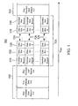
- FIG. 1 charts a communication segment 500 in this embodiment which is preferably implemented using a microprocessor or similar controller in each communicating unit and begins with a non-overlaid communication period 510 commencing with a non-overlaid communication start beacon 512.
- the segment 512 includes a header pattern which allows all nodes to easily recognize that it is a non-overlaid communication start beacon 512, as well as the length of time non-overlaid communication will be available.
- the start beacon 512 may additionally carry other information; for example, it may specify when the beginning and end of various communication periods will occur as well as their lengths. The inclusion of such information allows all nodes to stay in synch with the network, even if they cannot interpret the messages during the overlaid communication period 524, or during the non-overlaid communication period 510. Also, since the non-overlaid communication start beacon 512 is broadcast over all available carriers all nodes will receive it, though nodes that can receive only a subset of carriers may not be able to interpret it.
- the next communication segment in the non-overlaid communication period 510 is the non-overlaid data communication period 514 which supports communication between nodes that can use all carrier frequencies within the multi-carrier communications channel. Since all available carriers are used by a single node during this period, the non-overlaid data communication period 514 cannot support overlaid communication. The non-overlaid data communication period 514 is useful for supporting nodes that are not able to use a subset of the available carriers. Additionally, since only one node is transmitting, the non-overlaid data communication period 514 can be used to support peer-to-peer communication without violating the need for time alignment, power control, and half duplex operation mode.
- Nodes that can receive only a subset of carriers will neither transmit nor receive during the non-overlaid data communication period 514 -- based on the overlaid beacons which these nodes can understand, they will know when to transmit and will not transmit outside of the overlaid period.
- a non-overlaid communication end beacon 516 complements the start beacon 512 and follows the non-overlaid data communication period 514.
- the end beacon 516 is an information segment signaled by a coordinator node over all available carriers.
- the beacon 516 includes a header pattern which allows all nodes to easily recognize that it is a non-overlaid communication end beacon 516, as well as the length of time before non-overlaid communication will again be available.
- the end beacon 516 may additionally carry other information as described above in connection with the non-overlaid start beacon 512. Since the non-overlaid communication end beacon 516 is broadcast over all available carriers all nodes will receive it, though nodes that can receive only a subset of carriers will not be able to interpret it as described in connection with the start beacon.
- the overlaid communication period 524 After the non-overlaid communication end beacon 516 comes the overlaid communication period 524. Its beginning is signaled by the overlaid communication start beacon 520 which parallels the non-overlaid communication start beacon 512 in its purpose.
- the overlaid communication start beacon 520 is transmitted on all available carriers so that even a node that can receive only one channel can recover the start beacon 520, and preferably contains a header which enables nodes to easily recognize it.
- the overlaid communication start beacon 520 preferably contains assignments of nodes to carrier frequencies as described above and, potentially, time slots for node shifting.
- the start beacon 520 also preferably specifies the length of the following overlaid data communication period 524, or alternatively the time at which the period 524 will end, as well as other information such as that described above in connection with the non-overlaid communication period 510. Nodes that are not able to handle overlaid communications may not understand this beacon. This is because current systems code the information across all carriers in a particular way. In this case, information is preferably coded serially down each carrier individually.
- the overlaid data communication period 524 follows the overlaid data communication start beacon 520. It is here that the basic overlaid communication scheme may be implemented. That is, the overlaid data communication period 524 supports overlaid signaling in which more than one node is transmitting at the same time and nodes use fewer than all of the available carrier frequencies. These different carriers are shown in FIG. 1 as different rows 526 in the overlaid data communication period 524.
- a given carrier 526 may be assigned to only one node for transmission. In the present embodiment, this means the node would occupy each data slot 528 for a particular carrier 526.
- a particular carrier 526 might be shared in time between several nodes including the controller node. Methods for sharing in time while in overlaid communication mode will be described in greater detail below. Nodes that cannot handle overlaid communications would neither transmit nor receive during the overlaid data communication period 524.
- the end of the overlaid data communication period 524 is signaled by an overlaid communication end beacon 530.
- this beacon 530 preferably includes an easily-recognizable header and indicates the time at which (or the delay before) the next overlaid communication period 524 begins. It might also carry information similar to that of the overlaid communication start beacon 520 described above.
- this beacon 530 is preferably transmitted on all available carriers to ensure that even nodes capable of accessing only a single channel will receive it. Nodes that do not know how to handle overlaid communications will not understand this beacon.
- the overlaid communication start beacon 520 and overlaid communication end beacon 530 preferably contain nearly the same information described above in connection with their non-overlaid counterpart beacons 512 and 516; however, the overlaid beacons 520 and 530 may contain different information on each carrier frequency 526. Some information such as the time reference and when the overlaid communication period 524 begins and ends needs to be transmitted on each carrier 526; however, other information such as which time slot 528 is assigned to which node for a given carrier 526 is unique to each carrier 526. Information unique to a given node, e.g., sleep/wake information, only needs to be transmitted on one of the carriers 526 assigned to that node. Also, the beacons 520 and 530 may contain information about which carrier/time slot pairs are available for nodes to request service.
- One further piece of information that the overlaid communication period beacons 520 and 530 need to carry is the assignment of nodes to frequency carriers 526. As shown in FIG. 1 , after the overlaid communication period 524 ends, operation preferably continues with a new communication segment 500.
- This super frame protocol may be readily adapted to work with existing industry standard protocols.
- the IEEE 802.11 standard specifies a PCF beacon which specifies an amount of time during which nodes are to remain silent as long as they are not requested to transmit by a poll message.
- This beacon could be used as the overlaid communication start beacon 520. Nodes that do not understand transmissions during the overlaid communication period 524 would remain silent based on the time period specified in the PCF beacon. After the time period 524 is up, these nodes would be free to communicate in their standard non-overlaid mode during the non-overlaid communication period 510.
- the IEEE 802.11 standard defines a CF-End beacon. This beacon announces the end of the polling period. It is used if the polling is completed before the time reserved in the PCF beacon period expires. This beacon could serve as the overlaid communication end beacon 530 to indicate that the overlaid communication period 524 has ended, thereby allowing nodes to begin communicating in their traditional non-overlaid manner in the next non-overlaid communication period 510.
- the frame protocol 500 of this embodiment may be readily adapted to work with the existing HiperlanII industry standard protocol.
- this protocol communication during the non-overlaid period is done by time division multiple access (TDMA). Since the assignment of time slots for transmissions is controlled, it is easy in this communication system to reserve a period of time during which overlaid communication would be supported.
- TDMA time division multiple access
- beacon concept is extended to denote special periods of time for:
- a calibration period has three components: a control indication from the access point, a controlled transmission period by certain selected stations, and a period where stations communicate information back to the access point.
- every station will have a MAC address as well as a station ID which may be either assigned by administrative means to each station or assigned by the access point to each station, or determined by a distributed voting algorithm or other means.
- a station ID which may be either assigned by administrative means to each station or assigned by the access point to each station, or determined by a distributed voting algorithm or other means.
- each of N wireless stations will have an ID which will be, for purposes of this example only, a value between 1 and N.
- the number of single carriers available for overlaid transmission is C.
- the access point begins a calibration period by broadcasting a message to all stations. This assigns a carrier frequency and power level to C, or fewer, stations. If the number of stations is greater than C, then multiple calibration periods can be initiated until all stations have been selected.
- One way of encoding the carrier assignment is to transmit a vector of length N where each of the N elements contains a carrier frequency value or identifier. However, it is more useful to transmit a vector with the number of elements equal to the number of available carriers. The number of carriers may be smaller than the number of stations in some instances, e.g., a large classroom or meeting room. Furthermore, this representation allows the AP to assign more than one carrier to a station.
- the access point In addition to assigning one or more carrier frequencies, the access point also assigns a power level for transmission. For a basic scheme the power levels could be represented as “low”, “medium”, and "high”.
- the access point In addition to assigning carrier frequencies and power levels, the access point also specifies a time interval for calibration. After receiving a calibration beacon message, each station that has been selected to transmit on one or more carriers will do so. Each station transmits a short message including, but not limited to, the station ID and power level. Because stations cannot both send and receive, a sufficient number of calibration periods must be scheduled so that all stations that wish to operate in overlaid mode have an opportunity to transmit during a calibration period.
- An access point can thus direct a set of stations to transmit on assigned carriers with an assigned power level for a certain period.
- This capability is the basis for creating a map or grid of stations that can "hear" one another at certain power levels at specified frequencies.
- One preferred method for using the calibration period by direction from an AP or other designated controller is: 1. all nodes transmit at low power (on different carriers assigned by AP). 2. all stations (up to C per period) record which carriers they can decode. They also record the received power level (e.g., "low”, “medium”, “high”). 3. all stations report results to AP either via a poll response or by transmitting in an assigned or implied slot following the calibration period. 4. process repeats with AP changing the set of nodes that transmit, their assigned carriers, and transmit power levels. 5. process converges to a map which could take the form shown in TABLE I. TABLE I station ID 1 2 3 1 low high 2 low low low 3 high low
- station pairs (1,2) and (2,3) can communicate at low power, and station pair (1,3) needs high power.
- (1,3) cannot use overlays at the same time as the others because station 2 would be saturated by station 3.
- a "brute force” process would involve testing all combinations of station, carrier frequencies, and power level. Clearly, reductions in testing complexity can be obtained by using observed receive power levels when transmitting lower power settings to identify “nearby” stations that will overpower “remote” stations as calibration power levels are increased.
- the end result of a sequence of calibration periods will be one or more matrices, or equivalent data structures, as described, with each preferably corresponding to a frequency assignment.
- the AP can keep this data for decision-making purposes, e.g., when making channel allocations for overlaid communications, and the AP may also transmit the matrix or selected subsections of the matrix to individual stations for their local use, or to prepare for the possibility that the AP function may migrate from one station to another.
- an AP Given a matrix or equivalent structure containing reachability information as described, an AP can make correct decisions about which stations may be allowed to participate in a overlaid timeslot. This information is necessary for both station-to-AP transmission in overlaid mode and station-to-station transmission when in overlaid mode.
- an additional mode of low-power operation may be defined.
- a station operates at a power setting so low that only devices within a small volume, e.g., 3 or 4 feet (approx. 90 to 120 cm), can communicate with one another.
- a small computer system might be a wireless station communicating through an access point and could also have a wireless keyboard or mouse and other local peripherals such as telephone sets and personal organizers that communicate only via low-power transmissions.
- the computer system and its peripherals can be thought of as a "constellation" of devices.
- the method of using a beacon or control methods derived from beacons can be used to define a time period, or time slot, during which all the stations under control of an access point communicate at very low power levels with the wireless devices in their local constellation. This method provides more sharing of the wireless channel than would otherwise be possible.
- nodes may communicate in a direct mode, i.e., station-to-station mode, instead of forwarding through an AP.
- a direct mode i.e., station-to-station mode
- This provides full channel bandwidth.
- direct mode communication is also possible in overlay mode, i.e., with multiple simultaneous active transmitters using non-conflicting carriers and power levels that have been selected using data acquired during a power-frequency calibration procedure.
- Direct overlaid communication can thus increase channel efficiency and bandwidth by increasing the number of active transmitters and receivers.
- An additional communication mode in which individual nodes act as bridges between two communicating peers without use of the AP can also be implemented.
- This mode extends the reach of an ad hoc network. Using this mode it is possible to have fewer cellular base stations in a cellular telephone system to cover the same area as long as there are a sufficient number ofphones willing to act as bridges between peer devices. On a smaller scale, one could cover a large office from a single AP that could reach all the wireless devices that were a few hops away by going through bridging stations instead of needing direct communications with every station.
- Some embodiments of the present invention implement only one of these communication modes in a dedicated fashion; however, another embodiment implements two or more of the modes using the super frame arrangement generally described above in connection with FIG. 1 in which a communication cycle is composed of several segments separated by start and end beacons for that mode.
- a system might operate according to a communication protocol establishing a communication cycle having a first period in which calibration communication is performed, followed by a second period of low power communication.
- This concept may be extended to include three or more modes within the communication cycle.
- Various ones of the modes may further be combined with one another to form hybrid modes which can be implemented as well. All of these may be used to render the physical communication medium in a form most appropriate for a particular type of data being carried thereon.
- Full-carrier communication on a wireless channel normally requires an acknowledgement after every transmission, and that behaviour can be duplicated in overlaid mode.
- Receivers can send acks using the same subset of overlaid carriers that were active when receiving messages.
- the burst sizes may be very small and the amount of time on the channel for sending sound samples may be comparable to the amount of time on the channel for sending acks. In such cases it can be useful to eliminate the customary acknowledgement after transmission.
- a missing sample can be approximated by interpolation, thus eliminating the need for retransmitting the lost sample.
- Other types of data e.g., analog sampled data having few or no high-frequency components, may also be used with this technique to avoid retransmission of packets.
- Certain applications may acknowledge and retransmit on error or implement error correction or data interpolation procedures as described for audio sampling.
- the packet sizes are small compared to the channel time needed for the normal wireless packet acknowledgement, the data transmission is not time critical, and the channel experiences sufficiently low noise and interference levels, then an improvement in channel efficiency can be provided by turning off the physical layer wireless acknowledgement procedures built into higher-level protocol layers.
Abstract
Description
- The present invention is directed to communication systems and networks and is particularly directed toward methods for controlling shared access to wireless transmission systems.
- Network systems and network traffic loads have evolved and stratified in several important dimensions. The systems have adapted to a great range of distances -- e.g., from personal area networks (PANs) to local area (LANs), metro area (MANs) and wide area (WANs). The bandwidth properties of the physical media have also grown to span a wide range of possibilities - there are significant transmission systems for kilobits, megabits, gigabits, and terabits. Traffic loads have grown from simple telecommunication and file transfer applications to include a wide variety of traffic types such as:
- -- bursty asynchronous small data (e.g., 1-128 byte messages);
- -- bursty asynchronous file/page data (e.g., 1-16 KB messages);
- -- bursty asynchronous bulk data (e.g., 1 MB and beyond);
- -- streaming (isochronous) small data, file data and bulk data;
- -- streaming (variable bit rate);
- -- multicast or broadcast data;
- -- guaranteed rate and/or guaranteed jitter; and
- -- prioritized traffic.
- It is important to consider how diverse traffic types can coexist on a given network or mix of networks. The effectiveness of different methods for carrying different kinds of traffic will vary with the geographic range of the network -- i.e., PAN, LAN, MAN, WAN -- with the available bandwidth on the medium, with the control scheme of the network, and with the mix of the traffic types loading the network.
- Many networking systems, e.g., Ethernet, were invented prior to the existence of a wide range of traffic types. Ethernet pioneered packet transmission over a contention medium and is not optimized for isochronous traffic. Other networks have been designed for different missions. Examples include Fibre Channel which was originally developed as an interconnect method for disk storage, and ATM which was originally designed for telephony and media traffic. Wireless networks, while sharing the wireless medium, have been developed with great diversity including both cell-based TDMA control (HiperLan) and Ethernet-like contention-based methods (IEEE 802.11).
- Contemporary wireless communication systems specify one or more communication "channels", or frequency bands, for stations to transmit and receive encoded data. The channels are used in one of two ways: a station transmits data to a control unit, usually called an access point (AP), which forwards the data to another station (forwarding mode), or a station may transmit data directly to a destination station without passing through an access point (direct mode).
- Forwarding mode provides an advantage in that stations that may not be able to transmit directly to each other because of range limitations or other problems can still communicate by forwarding through the access point. One disadvantage of this method is that data must traverse the channel twice, thus reducing the total available bandwidth by half.
- The access point in wireless networking supplies control methods and protocols that coordinate the various transfers between wireless stations. It is common practice to define an ad hoc network as a set of wireless stations without a dedicated access point. In this configuration it is assumed that some, if not all, of the stations are capable of serving as access point and that a selection procedure exists whereby one of the stations will provide the necessary control functions.
- The IEEE 802.11a standard specifies multiple channels each consisting of multiple carrier frequencies with several possible modulation schemes, e.g., OFDM, defined for the channels. In typical practice a channel is operated as a monolithic unit where a transmitter always sends on the complete set of carriers defined for a channel and a receiver always receives from the complete set of carriers. New technologies have been invented whereby a transmitter can use a subset of the carriers while other transmitters simultaneously utilize a different non-conflicting set of carriers from the same channel. This technology introduces a new operational mode for the channel which can be called "overlaid mode". Thus, multiple transmitters can be using a channel in overlaid mode whereas in the normal non-overlaid mode only a single transmitter can be active.
- With the addition of an overlaid mode, conventional channels that would otherwise have only two modes (forwarding or direct) could have at least four modes: forwarding, forwarding+overlaid (where the transmitter communicates with the receiver via the access point over only a subset of the full carrier set), direct, and direct+overlaid (where the transmitter communicates with the receiver directly over only a subset of the full carrier set).
- Wireless networks and particularly networks with multi-carrier channels have certain constraints:
- radios used in wireless networking are not able to simultaneously send and receive (because the transmitter would overwhelm a local receiver); and
- power received on different carriers in a multi-carrier system must be approximately equal across all the carriers; otherwise signals on stronger carriers will overwhelm weaker carriers in systems where a common amplifier with automatic gain control processes all of the carriers.
- There are a number of factors such as uniform timing, frequency stability, multi-path and noise phenomena that are preferably considered as well in creating a viable overlaid transmission system. The issue of power control in the overlaid mode is another of these. There exist both open-loop and closed-loop power control methods that help a single transmitter adjust its power output, and help a single receiver adjust its receiver gain, when a particular transmitter/receiver pair is active. These procedures are not applicable when either
- multiple transmitters are sending to the same receiver at the same time; or
- multiple transmitters are engaged in direct transfers in an overlaid mode at the same time.
- A wireless transmission system experiences much higher bit error rates, or packet error rates, than a comparable wired transmission system. In order to make wireless systems robust the physical layer design of wireless systems typically incorporates some or all of the following adaptive techniques:
- -- means to select a more robust, and hence lower data rate, encoding scheme when the channel is noisy or a less redundant and a higher data rate encoding scheme when the channel is clear;
- -- means to quickly acknowledge the correct reception of a packet -- and thus to quickly retransmit the packet if necessary -- in order to reduce the packet error rate; and
- -- means to change frequencies or channels in a dynamic manner in order to move from a frequency band that is noisy or affected by multi-path effects to a different frequency band that is better.
- These techniques for improving channel robustness must be reconsidered, modified, or replaced in the context of overlaid communication. The frequency assignment problem is more complicated because multiple carriers must be assigned to multiple transmitters instead of all carriers being assigned to a single transmitter. The traditional method of acknowledging a transmitted packet must be reconsidered in overlaid mode because there are multiple simultaneous packets to acknowledge rather than a single packet. Mobile stations may need to change carrier frequencies, but it will be difficult to determine which frequencies are available and which frequencies might offer some improvement.
- Access methods for wireless channels fall into three general categories: contention methods, polling methods, and TDMA methods. Contention systems such as IEEE 802.11 use heuristics - e.g., random backoff, listen-before-talk, and mandated interframe delay periods - to avoid (but not completely eliminate) collisions on the wireless medium. IEEE 802.11 also employs a beacon message which can be asserted by the access point and which allows the access point to individually poll selected stations for sending or receiving data. The duration of the polling period is controlled by a parameter set by the access point and contained within the beacon message. Slotted systems, e.g., TDMA, assign timeslots to individual transmitters to eliminate collision and assign predictable amounts of bandwidth. The contention systems are well-suited to asynchronous bursty traffic. These systems work particularly well when the burst sizes are comparable to the natural packet size of the medium, or small multiples of the natural packet size. Slotted systems are well-suited to isochronous applications that have a need for continuous channel bandwidth, although they may have extra overhead in comparison to contention systems when carrying asynchronous bursty traffic.
- Methods have been devised to map different kinds of traffic to a particular medium, i.e., to give slotted media some of the attributes of contention media and vice versa. For example, Fibre Channel classes and ATM adaptation layers or convergence layers specify procedures for mapping different kinds of traffic onto underlying media. In all cases these are mappings onto an underlying medium - packet-based in the case of Fibre Channel or cell-based in the case of ATM. Mappings and convergence layers are separate and distinct from the underlying physical medium, and the distinction is equally appropriate for wireless network which have been designed to operate either as contention networks or slotted or TDMA networks.
- ADACHI & NAKAGAWA, IEICE TRANS COMMUN July 1998, pgs 1500-1506, discloses a system where a decision is made of whether two mobile terminals are sufficiently near to each other to communicate directly or if a cellular system should be used. To make this decision, a first mobile terminal compares a signal from a base station with a signal from the second mobile terminal to determine which signal is stronger. If the signal from the second mobile terminal is stronger, then direct contact is made. Otherwise, the cellular system is used.
-
US 5,357,513 discloses a mobile telephone system that exploits inactive periods during a telephone conversation to increase the capacity of the system. When a mobile detects the onset of a speech spurt, the mobile formulates a channel allocation request and is assigned a channel. The mobile tunes its transmitter to the identified channel and begins transmission of the speech spurt. Thus, a channel is only allocated to a particular mobile when required. -
EP-A-1063819 discloses a calibration procedure of wireless networks to create a topology map mainly consisting of two phases: a measurement phase during which each wireless device, i.e. all mobile terminals end the central controller, transmits a calibration signal in broadcast mode and each other wireless device measures the received signal quality and the reporting phase during which each mobile terminal reports the measured results to the central controller of the network. - In view of the above, it is an object of the present invention to provide a more efficient wireless transmission system by calibrating transmit power levels in an overlaid multi-carrier system with changing conditions or mobile stations.
- According to a first aspect of the present invention, there is provided a method of establishing communications in a multi-carrier communication system between a plurality of wireless stations each wireless station handling communication on less than all carriers in the multi-carrier communication system, the method comprising the steps of: providing each of the plurality of wireless stations with at least one assignment message that includes an assigned carrier and a commonly assigned calibration transmit power level for transmission; allowing a period of time for each of the plurality of wireless stations to transmit a plurality of calibration messages on the assigned carrier at the commonly assigned calibration power levels, wherein the plurality of calibration messages for each of the plurality of wireless stations are transmitted at different power levels designated by the at least one assignment message; receiving from each of the plurality of wireless stations information regarding transmissions received from other ones of the plurality of wireless stations, the information including the receive power level of each of the received transmissions; and using the received information to map which ones of the plurality of wireless stations can communicate with other ones of the plurality of wireless stations on assigned carriers, at a common transmit power level chosen from a plurality of available transmit power levels.
- According to a second aspect of the present invention, there is provided a multi-carrier communication system comprising a plurality of wireless stations in which each wireless station handles communication on less than all carriers in the multi-carrier communication system, the system being constructed and arranged such that: each of the plurality of wireless stations is provided with at least one assignment message that includes an assigned carrier and a commonly assigned calibration transmit power level for transmission, a period of time is allowed for each of the plurality of wireless stations to transmit a plurality of calibration messages on the assigned carrier at the commonly assigned calibration power levels, wherein each of the plurality of calibration messages for each of the plurality of wireless stations is transmitted at different power levels designated by the at least one assignment message; information regarding transmissions received from other ones of the plurality of wireless stations is received from each of the plurality of wireless stations, the information including the receive power level of each of the received transmissions; and a map is made using the received information to map which ones of the plurality of wireless stations can communicate with other ones of the plurality of wireless stations on assigned carriers, at a common transmit power level chosen from a plurality of available transmit power levels.
- A wireless communication system implements a calibration mode by which individual nodes in the system can determine which other nodes in the system are physically close to them and therefore can be reached with less than full transmitting power. It may also implement a calibration mode by which the signal quality at different carrier frequencies can be determined for pairs of stations. Nodes which can communicate with one another via low power can form a low power constellation (a subset of the complete network) whose nodes can communicate directly with one another using this low power arrangement. The direct communication mode may additionally be used by itself. In another mode, the nodes in the system can communicate amongst themselves via bridges - other, non-access point nodes - to lessen the load on the access point or to accommodate environmental or other conditions. Various ones of these modes may be combined into a predetermined cycle of communication modes to help the physical layer accommodate various types of data handled by the network using beacons or another coordinating technique. Overhead in the form of packet retransmission may be reduced by interpolating to recover lost packets rather than retransmitting them.
- Embodiments of the present invention will hereinafter be described, with reference to the accompanying drawings, in which:
-
Figure 1 is a timing chart of a frame protocol according to a preferred embodiment of the present invention. - The overlaid communication system described above may be used as part of an integrated overlaid/non-overlaid "super-frame communication system.
Figure 1 charts acommunication segment 500 in this embodiment which is preferably implemented using a microprocessor or similar controller in each communicating unit and begins with anon-overlaid communication period 510 commencing with a non-overlaid communication startbeacon 512. This is an information segment signalled by a coordinator node (a base station, a node that has been elected or volunteered to perform system coordination functions, or a number of nodes among which the coordination function is handed in an ad hoc network where there is no established infrastructure such as an established base station) over all available carriers; alternatively, for robustness and distributed ad hoc operation the duty of sending thenon-overlaid start beacon 512 may be shared amongst the nodes. In this case there would not be one fixed permanent coordinator, but each of the nodes would act as coordinator on a temporary basis. - Preferably, the
segment 512 includes a header pattern which allows all nodes to easily recognize that it is a non-overlaid communication startbeacon 512, as well as the length of time non-overlaid communication will be available. Thestart beacon 512 may additionally carry other information; for example, it may specify when the beginning and end of various communication periods will occur as well as their lengths. The inclusion of such information allows all nodes to stay in synch with the network, even if they cannot interpret the messages during the overlaidcommunication period 524, or during thenon-overlaid communication period 510. Also, since the non-overlaid communication startbeacon 512 is broadcast over all available carriers all nodes will receive it, though nodes that can receive only a subset of carriers may not be able to interpret it. This is particularly the case where when the signal is sent on all carriers it is coded across all the carriers, so that if a node cannot receive all carriers it cannot understand the signal. This is characteristic of systems that are backwards-compatible with nodes implementing protocols such as HiperlanII or IEEE 802.11. - The next communication segment in the
non-overlaid communication period 510 is the non-overlaiddata communication period 514 which supports communication between nodes that can use all carrier frequencies within the multi-carrier communications channel. Since all available carriers are used by a single node during this period, the non-overlaiddata communication period 514 cannot support overlaid communication. The non-overlaiddata communication period 514 is useful for supporting nodes that are not able to use a subset of the available carriers. Additionally, since only one node is transmitting, the non-overlaiddata communication period 514 can be used to support peer-to-peer communication without violating the need for time alignment, power control, and half duplex operation mode. Nodes that can receive only a subset of carriers will neither transmit nor receive during the non-overlaiddata communication period 514 -- based on the overlaid beacons which these nodes can understand, they will know when to transmit and will not transmit outside of the overlaid period. - A non-overlaid
communication end beacon 516 complements thestart beacon 512 and follows the non-overlaiddata communication period 514. Like its counterpart, theend beacon 516 is an information segment signaled by a coordinator node over all available carriers. Preferably, thebeacon 516 includes a header pattern which allows all nodes to easily recognize that it is a non-overlaidcommunication end beacon 516, as well as the length of time before non-overlaid communication will again be available. Theend beacon 516 may additionally carry other information as described above in connection with thenon-overlaid start beacon 512. Since the non-overlaidcommunication end beacon 516 is broadcast over all available carriers all nodes will receive it, though nodes that can receive only a subset of carriers will not be able to interpret it as described in connection with the start beacon. - After the non-overlaid
communication end beacon 516 comes the overlaidcommunication period 524. Its beginning is signaled by the overlaidcommunication start beacon 520 which parallels the non-overlaid communication startbeacon 512 in its purpose. The overlaidcommunication start beacon 520 is transmitted on all available carriers so that even a node that can receive only one channel can recover thestart beacon 520, and preferably contains a header which enables nodes to easily recognize it. The overlaidcommunication start beacon 520 preferably contains assignments of nodes to carrier frequencies as described above and, potentially, time slots for node shifting. Thestart beacon 520 also preferably specifies the length of the following overlaiddata communication period 524, or alternatively the time at which theperiod 524 will end, as well as other information such as that described above in connection with thenon-overlaid communication period 510. Nodes that are not able to handle overlaid communications may not understand this beacon. This is because current systems code the information across all carriers in a particular way. In this case, information is preferably coded serially down each carrier individually. - As mentioned above, the overlaid
data communication period 524 follows the overlaid datacommunication start beacon 520. It is here that the basic overlaid communication scheme may be implemented. That is, the overlaiddata communication period 524 supports overlaid signaling in which more than one node is transmitting at the same time and nodes use fewer than all of the available carrier frequencies. These different carriers are shown inFIG. 1 asdifferent rows 526 in the overlaiddata communication period 524. During the overlaiddata communication period 524, a givencarrier 526 may be assigned to only one node for transmission. In the present embodiment, this means the node would occupy eachdata slot 528 for aparticular carrier 526. Also, aparticular carrier 526 might be shared in time between several nodes including the controller node. Methods for sharing in time while in overlaid communication mode will be described in greater detail below. Nodes that cannot handle overlaid communications would neither transmit nor receive during the overlaiddata communication period 524. - The end of the overlaid
data communication period 524 is signaled by an overlaidcommunication end beacon 530. As with its non-overlaid counterpart, thisbeacon 530 preferably includes an easily-recognizable header and indicates the time at which (or the delay before) the next overlaidcommunication period 524 begins. It might also carry information similar to that of the overlaidcommunication start beacon 520 described above. Like the non-overlaidcommunication end beacon 516, thisbeacon 530 is preferably transmitted on all available carriers to ensure that even nodes capable of accessing only a single channel will receive it. Nodes that do not know how to handle overlaid communications will not understand this beacon. - The overlaid
communication start beacon 520 and overlaidcommunication end beacon 530 preferably contain nearly the same information described above in connection with theirnon-overlaid counterpart beacons beacons carrier frequency 526. Some information such as the time reference and when the overlaidcommunication period 524 begins and ends needs to be transmitted on eachcarrier 526; however, other information such as whichtime slot 528 is assigned to which node for a givencarrier 526 is unique to eachcarrier 526. Information unique to a given node, e.g., sleep/wake information, only needs to be transmitted on one of thecarriers 526 assigned to that node. Also, thebeacons - One further piece of information that the overlaid
communication period beacons frequency carriers 526. As shown inFIG. 1 , after the overlaidcommunication period 524 ends, operation preferably continues with anew communication segment 500. - This super frame protocol may be readily adapted to work with existing industry standard protocols. For example, the IEEE 802.11 standard specifies a PCF beacon which specifies an amount of time during which nodes are to remain silent as long as they are not requested to transmit by a poll message. This beacon could be used as the overlaid
communication start beacon 520. Nodes that do not understand transmissions during the overlaidcommunication period 524 would remain silent based on the time period specified in the PCF beacon. After thetime period 524 is up, these nodes would be free to communicate in their standard non-overlaid mode during thenon-overlaid communication period 510. - Further, the IEEE 802.11 standard defines a CF-End beacon. This beacon announces the end of the polling period. It is used if the polling is completed before the time reserved in the PCF beacon period expires. This beacon could serve as the overlaid
communication end beacon 530 to indicate that the overlaidcommunication period 524 has ended, thereby allowing nodes to begin communicating in their traditional non-overlaid manner in the nextnon-overlaid communication period 510. - Similarly, the
frame protocol 500 of this embodiment may be readily adapted to work with the existing HiperlanII industry standard protocol. In this protocol, communication during the non-overlaid period is done by time division multiple access (TDMA). Since the assignment of time slots for transmissions is controlled, it is easy in this communication system to reserve a period of time during which overlaid communication would be supported. - In a system such as IEEE 802.11 which has start-beacon and end-beacon signals and the system described above where the beacon defines a time period for slotted overlaid transmission, in preferred embodiments of the present invention the beacon concept is extended to denote special periods of time for:
- -- carrier calibration;
- -- slotted non-overlaid communication; and
- -- local constellation communication.
Preferred methods for specifying one of these time periods include the following: - -- encoding the type of period using bits that may be available in the beacon message itself;
- -- encoding the type of period in a specially-designed message that immediately follows the beacon message;
- -- encoding the type of period by using a non-existent station ID in an 802.11-defined beacon or polling message; and
- -- by prearrangement using either administrative control or a message exchange using ordinary means between access point and individual stations.
- A method for defining and using the calibration period will first be described. A calibration period has three components: a control indication from the access point, a controlled transmission period by certain selected stations, and a period where stations communicate information back to the access point.
- By definition, all stations collaborating with an access point must be able to exchange data messages with that access point. Also, every station will have a MAC address as well as a station ID which may be either assigned by administrative means to each station or assigned by the access point to each station, or determined by a distributed voting algorithm or other means. By one method or another each of N wireless stations will have an ID which will be, for purposes of this example only, a value between 1 and N. The number of single carriers available for overlaid transmission is C.
- The access point begins a calibration period by broadcasting a message to all stations.
This assigns a carrier frequency and power level to C, or fewer, stations. If the number of stations is greater than C, then multiple calibration periods can be initiated until all stations have been selected. One way of encoding the carrier assignment is to transmit a vector of length N where each of the N elements contains a carrier frequency value or identifier. However, it is more useful to transmit a vector with the number of elements equal to the number of available carriers. The number of carriers may be smaller than the number of stations in some instances, e.g., a large classroom or meeting room. Furthermore, this representation allows the AP to assign more than one carrier to a station. - In addition to assigning one or more carrier frequencies, the access point also assigns a power level for transmission. For a basic scheme the power levels could be represented as "low", "medium", and "high".
- In addition to assigning carrier frequencies and power levels, the access point also specifies a time interval for calibration. After receiving a calibration beacon message, each station that has been selected to transmit on one or more carriers will do so. Each station transmits a short message including, but not limited to, the station ID and power level. Because stations cannot both send and receive, a sufficient number of calibration periods must be scheduled so that all stations that wish to operate in overlaid mode have an opportunity to transmit during a calibration period.
- An access point can thus direct a set of stations to transmit on assigned carriers with an assigned power level for a certain period. This capability is the basis for creating a map or grid of stations that can "hear" one another at certain power levels at specified frequencies.
- One preferred method for using the calibration period by direction from an AP or other designated controller is:
1. all nodes transmit at low power (on different carriers assigned by AP).
2. all stations (up to C per period) record which carriers they can decode. They also record the received power level (e.g., "low", "medium", "high").
3. all stations report results to AP either via a poll response or by transmitting in an assigned or implied slot following the calibration period.
4. process repeats with AP changing the set of nodes that transmit, their assigned carriers, and transmit power levels.
5. process converges to a map which could take the form shown in TABLE I.TABLE I station ID 1 2 3 1 low high 2 low low 3 high low - This shows that station pairs (1,2) and (2,3) can communicate at low power, and station pair (1,3) needs high power. Thus (1,3) cannot use overlays at the same time as the others because
station 2 would be saturated by station 3. - A "brute force" process would involve testing all combinations of station, carrier frequencies, and power level. Clearly, reductions in testing complexity can be obtained by using observed receive power levels when transmitting lower power settings to identify "nearby" stations that will overpower "remote" stations as calibration power levels are increased.
- The end result of a sequence of calibration periods will be one or more matrices, or equivalent data structures, as described, with each preferably corresponding to a frequency assignment.
The AP can keep this data for decision-making purposes, e.g., when making channel allocations for overlaid communications, and the AP may also transmit the matrix or selected subsections of the matrix to individual stations for their local use, or to prepare for the possibility that the AP function may migrate from one station to another. - Given a matrix or equivalent structure containing reachability information as described, an AP can make correct decisions about which stations may be allowed to participate in a overlaid timeslot. This information is necessary for both station-to-AP transmission in overlaid mode and station-to-station transmission when in overlaid mode.
- Given a wireless transmission system with output power control and the ability to perform a power-frequency calibration procedure as described above, an additional mode of low-power operation may be defined. In this mode, a station operates at a power setting so low that only devices within a small volume, e.g., 3 or 4 feet (approx. 90 to 120 cm), can communicate with one another. For example, a small computer system might be a wireless station communicating through an access point and could also have a wireless keyboard or mouse and other local peripherals such as telephone sets and personal organizers that communicate only via low-power transmissions. The computer system and its peripherals can be thought of as a "constellation" of devices. The method of using a beacon or control methods derived from beacons can be used to define a time period, or time slot, during which all the stations under control of an access point communicate at very low power levels with the wireless devices in their local constellation.
This method provides more sharing of the wireless channel than would otherwise be possible. - Additional communication modes may be supported in the preferred embodiments. For example, nodes may communicate in a direct mode, i.e., station-to-station mode, instead of forwarding through an AP. This provides full channel bandwidth. Moreover, direct mode communication is also possible in overlay mode, i.e., with multiple simultaneous active transmitters using non-conflicting carriers and power levels that have been selected using data acquired during a power-frequency calibration procedure. Direct overlaid communication can thus increase channel efficiency and bandwidth by increasing the number of active transmitters and receivers.
- An additional communication mode in which individual nodes act as bridges between two communicating peers without use of the AP can also be implemented. This mode extends the reach of an ad hoc network. Using this mode it is possible to have fewer cellular base stations in a cellular telephone system to cover the same area as long as there are a sufficient number ofphones willing to act as bridges between peer devices. On a smaller scale, one could cover a large office from a single AP that could reach all the wireless devices that were a few hops away by going through bridging stations instead of needing direct communications with every station.
- Some embodiments of the present invention implement only one of these communication modes in a dedicated fashion; however, another embodiment implements two or more of the modes using the super frame arrangement generally described above in connection with
FIG. 1 in which a communication cycle is composed of several segments separated by start and end beacons for that mode.
For example, a system might operate according to a communication protocol establishing a communication cycle having a first period in which calibration communication is performed, followed by a second period of low power communication. This concept may be extended to include three or more modes within the communication cycle. Various ones of the modes may further be combined with one another to form hybrid modes which can be implemented as well. All of these may be used to render the physical communication medium in a form most appropriate for a particular type of data being carried thereon. - Full-carrier communication on a wireless channel normally requires an acknowledgement after every transmission, and that behaviour can be duplicated in overlaid mode. Receivers can send acks using the same subset of overlaid carriers that were active when receiving messages. However, for short bursty or short isochronous traffic such as audio or voice traffic, the burst sizes may be very small and the amount of time on the channel for sending sound samples may be comparable to the amount of time on the channel for sending acks. In such cases it can be useful to eliminate the customary acknowledgement after transmission. With interleaved audio samples, a missing sample can be approximated by interpolation, thus eliminating the need for retransmitting the lost sample. Other types of data, e.g., analog sampled data having few or no high-frequency components, may also be used with this technique to avoid retransmission of packets.
- There are other circumstances where it can be beneficial to eliminate traditional wireless packet acknowledgements. Certain applications, e.g., datagram applications utilizing the UDP protocol, may acknowledge and retransmit on error or implement error correction or data interpolation procedures as described for audio sampling. In cases where the packet sizes are small compared to the channel time needed for the normal wireless packet acknowledgement, the data transmission is not time critical, and the channel experiences sufficiently low noise and interference levels, then an improvement in channel efficiency can be provided by turning off the physical layer wireless acknowledgement procedures built into higher-level protocol layers.
- It will be appreciated that variations in, and modifications to, the embodiments disclosed and illustrated may be made within the scope of the appended claims.
Claims (16)
- A method of establishing communications in a multi-carrier communication system between a plurality of wireless stations each wireless station handling communication on less than all carriers in the multi-carrier communication system, the method comprising the steps of:providing each of the plurality of wireless stations with at least one assignment message that includes an assigned carrier and a commonly assigned calibration transmit power level for transmission;allowing a period of time for each of the plurality of wireless stations to transmit a plurality of calibration messages on the assigned carrier at the commonly assigned calibration power levels, wherein the plurality of calibration messages for each of the plurality of wireless stations are transmitted at different power levels designated by the at least one assignment message;receiving from each of the plurality of wireless stations information regarding transmissions received from other ones of the plurality of wireless stations, the information including the receive power level of each of the received transmissions; andusing the received information to map which ones of the plurality of wireless stations can communicate with other ones of the plurality of wireless stations on assigned carriers, at a common transmit power level chosen from a plurality of available transmit power levels.
- A method according to claim 1, wherein each of the plurality of power calibration messages for each of the plurality of wireless stations is transmitted at increasing power levels.
- A method according to claim 1, wherein each of the plurality of power calibration messages for each of the plurality of wireless stations is transmitted at decreasing power levels.
- A method according to any preceding claim, wherein the steps of providing and receiving occur at the another wireless station.
- A method according to claim 4, wherein the another wireless station is an access point.
- A method according to any preceding claim, wherein it is determined that a first wireless station communicating with a second wireless station at one of the available power levels at the same time prevents a third wireless station from communicating.
- A method according to claim 6, wherein it is determined that the first wireless station communicating with the second wireless station at one of the available power levels at the same time saturates the third wireless station.
- A method according to any preceding claim, wherein the message further specifies a period of time.
- A method according to any preceding claim, wherein the message further specifies one of a plurality of calibration periods that exist during a period of time for each of the plurality of wireless stations to transmit on the assigned carrier and at the assigned power level.
- A method according to claim 9, wherein each of the plurality of wireless stations transmit during the period of time the calibration message containing therein an identifier of the transmitting wireless station and a transmit power level at which the calibration message is being transmitted.
- A method according to claim 10, wherein the received calibration message from various ones of the transmitting wireless stations is collected at each receiving wireless station and used to obtain the information during the step of receiving.
- A method according to any preceding claim, wherein the step of providing the message provides the carrier assignment using a vector having a number of elements equal to a number of available carriers.
- A method according to any preceding claim, further including a transmission period during which the plurality of wireless stations communicate within constraints of the map.
- A method according to claim 13, wherein during the transmission period, at least one pair of the plurality of wireless stations communicate without an acknowledgement after a transmission.
- A method according to any preceding claim, wherein during the period of time, transmissions of different calibration messages on respectively different carriers can take place at the same time.
- A multi-carrier communication system comprising a plurality of wireless stations in which each wireless station handles communication on less than all carriers in the multi-carrier communication system, the system being constructed and arranged such that:each of the plurality of wireless stations is provided with at least one assignment message that includes an assigned carrier and a commonly assigned calibration transmit power level for transmission,a period of time is allowed for each of the plurality of wireless stations to transmit a plurality of calibration messages on the assigned carrier at the commonly assigned calibration power levels, wherein each of the plurality of calibration messages for each of the plurality of wireless stations is transmitted at different power levels designated by the at least one assignment message;information regarding transmissions received from other ones of the plurality of wireless stations is received from each of the plurality of wireless stations, the information including the receive power level of each of the received transmissions; anda map is made using the received information to map which ones of the plurality of wireless stations can communicate with other ones of the plurality of wireless stations on assigned carriers, at a common transmit power level chosen from a plurality of available transmit power levels.
Applications Claiming Priority (3)
| Application Number | Priority Date | Filing Date | Title |
|---|---|---|---|
| US19905000P | 2000-04-22 | 2000-04-22 | |
| US199050P | 2000-04-22 | ||
| PCT/US2001/012920 WO2001082500A2 (en) | 2000-04-22 | 2001-04-20 | Methods for controlling shared access to wireless transmission systems and increasing throughput of the same |
Publications (2)
| Publication Number | Publication Date |
|---|---|
| EP1282964A2 EP1282964A2 (en) | 2003-02-12 |
| EP1282964B1 true EP1282964B1 (en) | 2009-09-02 |
Family
ID=22735996
Family Applications (1)
| Application Number | Title | Priority Date | Filing Date |
|---|---|---|---|
| EP01927269A Expired - Lifetime EP1282964B1 (en) | 2000-04-22 | 2001-04-20 | Method for controlling shared access to wireless transmission systems and increasing throughput of the same |
Country Status (7)
| Country | Link |
|---|---|
| US (1) | US6795407B2 (en) |
| EP (1) | EP1282964B1 (en) |
| AT (1) | ATE441990T1 (en) |
| AU (1) | AU2001253740A1 (en) |
| DE (1) | DE60139771D1 (en) |
| TW (1) | TW512603B (en) |
| WO (1) | WO2001082500A2 (en) |
Families Citing this family (71)
| Publication number | Priority date | Publication date | Assignee | Title |
|---|---|---|---|---|
| US7308279B1 (en) | 2000-08-18 | 2007-12-11 | Nortel Networks Limited | Dynamic power level control on transmitted messages in a wireless LAN |
| US7280495B1 (en) | 2000-08-18 | 2007-10-09 | Nortel Networks Limited | Reliable broadcast protocol in a wireless local area network |
| US7366103B2 (en) * | 2000-08-18 | 2008-04-29 | Nortel Networks Limited | Seamless roaming options in an IEEE 802.11 compliant network |
| US7339892B1 (en) | 2000-08-18 | 2008-03-04 | Nortel Networks Limited | System and method for dynamic control of data packet fragmentation threshold in a wireless network |
| US6807165B2 (en) * | 2000-11-08 | 2004-10-19 | Meshnetworks, Inc. | Time division protocol for an ad-hoc, peer-to-peer radio network having coordinating channel access to shared parallel data channels with separate reservation channel |
| US6965575B2 (en) * | 2000-12-29 | 2005-11-15 | Tropos Networks | Selection of routing paths based upon path quality of a wireless mesh network |
| GB0110125D0 (en) | 2001-04-25 | 2001-06-20 | Koninkl Philips Electronics Nv | Radio communication system |
| WO2002103970A1 (en) * | 2001-06-18 | 2002-12-27 | Tatara Systems, Inc. | Method and apparatus for converging local area and wide area wireless data networks |
| JP4046961B2 (en) * | 2001-09-03 | 2008-02-13 | キヤノン株式会社 | Position detection method, position detection apparatus, exposure apparatus, and exposure method |
| CA2461733A1 (en) * | 2001-10-03 | 2003-04-10 | Sergio T. Montano | Method of operating a media access controller |
| US7346357B1 (en) | 2001-11-08 | 2008-03-18 | At&T Corp. | Frequency assignment for multi-cell IEEE 802.11 wireless networks |
| US20030087645A1 (en) | 2001-11-08 | 2003-05-08 | Kim Byoung-Jo J. | Frequency assignment for multi-cell IEEE 802.11 wireless networks |
| WO2003047175A1 (en) * | 2001-11-28 | 2003-06-05 | Millennial Net | Etwork protocol for an ad hoc wireless network |
| TW561757B (en) * | 2002-03-20 | 2003-11-11 | Quanta Comp Inc | System and method for a mobile station to handle resource collision between tasks |
| US7606573B1 (en) | 2002-09-27 | 2009-10-20 | Autocell Laboratories, Inc. | Wireless switched network |
| US7698550B2 (en) * | 2002-11-27 | 2010-04-13 | Microsoft Corporation | Native wi-fi architecture for 802.11 networks |
| JP4100182B2 (en) * | 2003-01-30 | 2008-06-11 | 松下電器産業株式会社 | Communication terminal device and control method thereof |
| CN100586086C (en) * | 2003-02-03 | 2010-01-27 | 索尼株式会社 | Radio communication system, radio communication device, radio communication method |
| US7869822B2 (en) | 2003-02-24 | 2011-01-11 | Autocell Laboratories, Inc. | Wireless network apparatus and system field of the invention |
| US7221943B2 (en) | 2003-02-24 | 2007-05-22 | Autocell Laboratories, Inc. | Wireless station protocol program |
| US8055753B2 (en) * | 2003-06-11 | 2011-11-08 | International Business Machines Corporation | Peer to peer job monitoring and control in grid computing systems |
| KR101002883B1 (en) * | 2003-10-27 | 2010-12-21 | 재단법인서울대학교산학협력재단 | Apparatus and method for controlling transmission power in a wireless communication system |
| KR100686775B1 (en) * | 2003-11-07 | 2007-02-23 | 삼성전자주식회사 | Method for transmitting traffic a indication message in broadband wireless access communication system |
| WO2005060300A1 (en) * | 2003-12-15 | 2005-06-30 | Philips Intellectual Property & Standards Gmbh | Wireless system comprising a first station and a second station system |
| US7133373B2 (en) * | 2003-12-19 | 2006-11-07 | Motorola, Inc. | Wireless network with improved sharing of high power consumption tasks |
| US7206550B2 (en) * | 2003-12-29 | 2007-04-17 | Intel Corporation | Antenna subsystem calibration apparatus and methods in spatial-division multiple-access systems |
| US8369790B2 (en) | 2003-12-30 | 2013-02-05 | Intel Corporation | Communication overhead reduction apparatus, systems, and methods |
| US7366169B1 (en) | 2004-02-18 | 2008-04-29 | Autocell Laboratories, Inc. | Apparatus for scanning radio frequency channels |
| US7684783B1 (en) | 2004-03-23 | 2010-03-23 | Autocell Laboratories, Inc. | System and method for authenticating devices in a wireless network |
| US7965686B1 (en) | 2004-03-26 | 2011-06-21 | Autocell Laboratories, Inc. | Selecting a wireless access point when load information is not provided by all access points |
| US20050213549A1 (en) * | 2004-03-26 | 2005-09-29 | Laura Bridge | System and method for access point/probe conversion |
| US7043277B1 (en) | 2004-05-27 | 2006-05-09 | Autocell Laboratories, Inc. | Automatically populated display regions for discovered access points and stations in a user interface representing a wireless communication network deployed in a physical environment |
| US7660263B1 (en) | 2004-05-27 | 2010-02-09 | Autocell Laboratories, Inc. | Graphical representations of associations between devices in a wireless communication network indicating available throughput and channel selection |
| US7283848B1 (en) | 2004-05-27 | 2007-10-16 | Autocell Laboratories, Inc. | System and method for generating display objects representing areas of coverage, available bandwidth and channel selection for wireless devices in a wireless communication network |
| US7774028B1 (en) | 2004-05-27 | 2010-08-10 | Autocell Laboratories, Inc. | System and method for stateful representation of wireless network devices in a user interface to a wireless communication environment planning and management system |
| MX2007001704A (en) * | 2004-08-12 | 2007-04-12 | Interdigital Tech Corp | Method and system for controlling access to a wireless communication medium. |
| US7378953B2 (en) | 2004-08-30 | 2008-05-27 | International Business Machines Corporation | Transmission between a sensor and a controller in a wireless sensor network |
| US7996746B2 (en) | 2004-10-12 | 2011-08-09 | Nortel Networks Limited | Structured low-density parity-check (LDPC) code |
| US20060171327A1 (en) * | 2005-02-03 | 2006-08-03 | Autocell Laboratories, Inc. | Interference source recognition for wireless LANs |
| US8345643B1 (en) | 2005-02-03 | 2013-01-01 | Piccata Fund Limited Liability Company | Exception processing for wireless roaming |
| US7505751B1 (en) | 2005-02-09 | 2009-03-17 | Autocell Laboratories, Inc. | Wireless mesh architecture |
| AR052591A1 (en) * | 2005-03-08 | 2007-03-21 | Qualcomm Flarion Tech | METHOD AND APPLIANCE FOR EFFICIENT SIGNS OF DIGITAL DIFFUSION IN A WIRELESS COMMUNICATIONS SYSTEM |
| US8483200B2 (en) | 2005-04-07 | 2013-07-09 | Interdigital Technology Corporation | Method and apparatus for antenna mapping selection in MIMO-OFDM wireless networks |
| US7813370B2 (en) * | 2005-04-25 | 2010-10-12 | Autocell Laboratories, Inc. | Facilitating wireless spectrum migration |
| US7773944B2 (en) * | 2005-06-06 | 2010-08-10 | Autocell Laboratories, Inc. | RF domains |
| US7636550B2 (en) * | 2005-06-23 | 2009-12-22 | Autocell Laboratories, Inc. | System and method for determining channel quality in a wireless network |
| US7505434B1 (en) | 2005-06-23 | 2009-03-17 | Autocell Laboratories, Inc. | VLAN tagging in WLANs |
| US7633901B2 (en) * | 2005-06-23 | 2009-12-15 | Autocell Laboratories, Inc. | Co-channel congestion method and apparatus |
| US20070002939A1 (en) * | 2005-06-29 | 2007-01-04 | Tellabs Operations, Inc. | Method and apparatus for testing a data path |
| KR100606103B1 (en) * | 2005-07-15 | 2006-07-31 | 삼성전자주식회사 | Methodd for performing handover between different mobile communication networks and the dual mode terminal therefor |
| KR101154979B1 (en) * | 2005-07-22 | 2012-06-18 | 엘지전자 주식회사 | apparatus for receiving and transmitting data of multi-carrier system and method for receiving and transmitting data using the same |
| US8411616B2 (en) | 2005-11-03 | 2013-04-02 | Piccata Fund Limited Liability Company | Pre-scan for wireless channel selection |
| JP4955014B2 (en) * | 2005-12-22 | 2012-06-20 | コーニンクレッカ フィリップス エレクトロニクス エヌ ヴィ | Radio station and method for operating radio station |
| US8218567B2 (en) * | 2007-03-12 | 2012-07-10 | Broadcom Corporation | Method and system for reducing transceiver power via a variable signal constellation |
| US8014728B2 (en) * | 2009-04-28 | 2011-09-06 | Broadcom Corporation | Pulsed interval radio calibration |
| US8730930B2 (en) * | 2011-05-31 | 2014-05-20 | Broadcom Corporation | Polling using B-ACK for occasional back-channel traffic in VoWIFI applications |
| US8868056B2 (en) | 2011-08-18 | 2014-10-21 | Qualcomm Incorporated | Systems and methods of device calibration |
| US9036603B2 (en) | 2012-08-03 | 2015-05-19 | Intel Corporation | Network assistance for device-to-device discovery |
| WO2014022776A1 (en) | 2012-08-03 | 2014-02-06 | Intel Corporation | Method and system for enabling device-to-device communication |
| CN104471876B (en) | 2012-08-03 | 2018-08-10 | 英特尔公司 | Include the 3GPP/M2M method and apparatus of equipment triggering recall/replacement feature |
| US8913518B2 (en) | 2012-08-03 | 2014-12-16 | Intel Corporation | Enhanced node B, user equipment and methods for discontinuous reception in inter-ENB carrier aggregation |
| US9191828B2 (en) | 2012-08-03 | 2015-11-17 | Intel Corporation | High efficiency distributed device-to-device (D2D) channel access |
| US9100160B2 (en) | 2012-08-03 | 2015-08-04 | Intel Corporation | Apparatus and method for small data transmission in 3GPP-LTE systems |
| US8873518B2 (en) * | 2012-09-24 | 2014-10-28 | Silver Spring Networks, Inc. | System and method for broadcasting messages to nodes within a wireless mesh network |
| EP2936866B1 (en) * | 2012-12-18 | 2018-10-03 | Telefonaktiebolaget LM Ericsson (publ) | Base station and method thereof |
| US9681354B2 (en) | 2013-08-08 | 2017-06-13 | Intel IP Corporation | Signaling radio bearer optimizations and other techniques for supporting small data transmissions |
| EP3031146B1 (en) | 2013-08-08 | 2019-02-20 | Intel IP Corporation | Method, apparatus and system for electrical downtilt adjustment in a multiple input multiple output system |
| US9326122B2 (en) | 2013-08-08 | 2016-04-26 | Intel IP Corporation | User equipment and method for packet based device-to-device (D2D) discovery in an LTE network |
| EP3352522B1 (en) * | 2015-09-17 | 2023-11-01 | LG Electronics Inc. | Method and device for performing lbt process on multiple carriers in wireless access system supporting unlicensed band |
| US9813141B1 (en) * | 2016-07-29 | 2017-11-07 | Sprint Communications Company L.P. | Dynamic control of automatic gain control (AGC) in a repeater system |
| JP7311404B2 (en) | 2019-11-21 | 2023-07-19 | 矢崎総業株式会社 | Beacon receiving terminal and wireless communication system |
Citations (1)
| Publication number | Priority date | Publication date | Assignee | Title |
|---|---|---|---|---|
| EP1063819A1 (en) * | 1999-06-23 | 2000-12-27 | Sony International (Europe) GmbH | Calibration procedure for wireless networks with direct mode traffic |
Family Cites Families (19)
| Publication number | Priority date | Publication date | Assignee | Title |
|---|---|---|---|---|
| DE3304823A1 (en) | 1983-02-11 | 1984-08-16 | Siemens AG, 1000 Berlin und 8000 München | METHOD FOR A TELECOMMUNICATION, IN PARTICULAR TELEPHONE EXTENSION PLANT WITH A DATA TRANSFER LINE SYSTEM, IN PARTICULAR WITH AN OPTICAL DATA TRANSMISSION LINE SYSTEM |
| US4866710A (en) * | 1988-02-22 | 1989-09-12 | Motorola, Inc. | Reuse groups for scan monitoring in digital cellular systems |
| RU2101870C1 (en) * | 1988-10-21 | 1998-01-10 | Томсон-ЦСФ | Method of modulated wave transmission, transmitting and receiving devices |
| US5657317A (en) * | 1990-01-18 | 1997-08-12 | Norand Corporation | Hierarchical communication system using premises, peripheral and vehicular local area networking |
| US5142690A (en) * | 1990-03-20 | 1992-08-25 | Scientific-Atlanta, Inc. | Cable television radio frequency data processor |
| US5357513A (en) * | 1990-12-06 | 1994-10-18 | Hughes Aircraft Company | Transmission power level adjustment in radio telephony |
| US5422887A (en) * | 1991-11-27 | 1995-06-06 | Ncr Corporation | Medium access protocol for wireless local area network |
| US5384777A (en) * | 1993-04-19 | 1995-01-24 | International Business Machines Corporation | Adaptive medium access control scheme for wireless LAN |
| US5768683A (en) * | 1993-09-01 | 1998-06-16 | Motorola, Inc. | Method for automatic re-transmission of voice messages by a mobile communication unit |
| CA2129193C (en) * | 1994-07-29 | 1999-07-20 | Peter E. Reissner | Access point tracking for mobile wireless network node |
| CA2168327C (en) * | 1995-01-30 | 2000-04-11 | Shinichi Kikuchi | A recording medium on which a data containing navigation data is recorded, a method and apparatus for reproducing a data according to navigationdata, a method and apparatus for recording a data containing navigation data on a recording medium. |
| US5987011A (en) * | 1996-08-30 | 1999-11-16 | Chai-Keong Toh | Routing method for Ad-Hoc mobile networks |
| JP3535344B2 (en) | 1997-05-30 | 2004-06-07 | 松下電器産業株式会社 | Multicarrier transmission method, data transmission device, mobile station device, and base station device |
| US5912921A (en) | 1997-08-20 | 1999-06-15 | Intermec Ip Corp. | Concurrent multiple data rate communications in a wireless local area network |
| EP0924896A1 (en) | 1997-12-17 | 1999-06-23 | Hewlett-Packard Company | Communicating isochronous and asynchronous data |
| EP0938208A1 (en) | 1998-02-22 | 1999-08-25 | Sony International (Europe) GmbH | Multicarrier transmission, compatible with the existing GSM system |
| SE522344C2 (en) * | 1999-02-26 | 2004-02-03 | Ericsson Telefon Ab L M | Method and device for wireless telecommunications |
| GB9919432D0 (en) | 1999-08-18 | 1999-10-20 | Baglin Neil E | Access platform |
| US7463600B2 (en) | 2000-01-20 | 2008-12-09 | Nortel Networks Limited | Frame structure for variable rate wireless channels transmitting high speed data |
-
2001
- 2001-04-20 AT AT01927269T patent/ATE441990T1/en not_active IP Right Cessation
- 2001-04-20 US US09/839,647 patent/US6795407B2/en not_active Expired - Lifetime
- 2001-04-20 EP EP01927269A patent/EP1282964B1/en not_active Expired - Lifetime
- 2001-04-20 WO PCT/US2001/012920 patent/WO2001082500A2/en active Application Filing
- 2001-04-20 DE DE60139771T patent/DE60139771D1/en not_active Expired - Fee Related
- 2001-04-20 AU AU2001253740A patent/AU2001253740A1/en not_active Abandoned
- 2001-05-29 TW TW090109550A patent/TW512603B/en not_active IP Right Cessation
Patent Citations (1)
| Publication number | Priority date | Publication date | Assignee | Title |
|---|---|---|---|---|
| EP1063819A1 (en) * | 1999-06-23 | 2000-12-27 | Sony International (Europe) GmbH | Calibration procedure for wireless networks with direct mode traffic |
Also Published As
| Publication number | Publication date |
|---|---|
| DE60139771D1 (en) | 2009-10-15 |
| US20020045428A1 (en) | 2002-04-18 |
| ATE441990T1 (en) | 2009-09-15 |
| WO2001082500A3 (en) | 2002-04-11 |
| TW512603B (en) | 2002-12-01 |
| AU2001253740A1 (en) | 2001-11-07 |
| US6795407B2 (en) | 2004-09-21 |
| WO2001082500A2 (en) | 2001-11-01 |
| EP1282964A2 (en) | 2003-02-12 |
Similar Documents
| Publication | Publication Date | Title |
|---|---|---|
| EP1282964B1 (en) | Method for controlling shared access to wireless transmission systems and increasing throughput of the same | |
| US10447386B2 (en) | Method and system for controlling access to a wireless communication medium | |
| US7352718B1 (en) | Spatial division multiple access for wireless networks | |
| US20060203795A1 (en) | Method for sharing bandwidth using reduced duty cycle signals and media access control | |
| CA2689852C (en) | Method for performing wireless switching | |
| KR20050058393A (en) | Method and apparatus for assuring quality of service in wireless local area networks | |
| JP2004530349A (en) | Increase link capacity through simultaneous transmission in centralized wireless LAN | |
| CA2584394A1 (en) | A system and method for dynamic adaptation of data rate and transmit power with a beaconing protocol | |
| US7656962B2 (en) | Method for transmitting signals in a radio communication system | |
| WO2023033184A1 (en) | Communication device and communication method | |
| KR200401646Y1 (en) | System for controlling access to a wireless communication medium | |
| Shimizu et al. | Performance evaluation of novel DSA scheme that combines polling method with random access method | |
| Kim | Link-adaptive medium access control protocols for high-speed wireless networks |
Legal Events
| Date | Code | Title | Description |
|---|---|---|---|
| PUAI | Public reference made under article 153(3) epc to a published international application that has entered the european phase |
Free format text: ORIGINAL CODE: 0009012 |
|
| 17P | Request for examination filed |
Effective date: 20021105 |
|
| AK | Designated contracting states |
Designated state(s): AT BE CH CY DE DK ES FI FR GB GR IE IT LI LU MC NL PT SE TR |
|
| AX | Request for extension of the european patent |
Extension state: AL LT LV MK RO SI |
|
| 17Q | First examination report despatched |
Effective date: 20041206 |
|
| 17Q | First examination report despatched |
Effective date: 20041206 |
|
| GRAP | Despatch of communication of intention to grant a patent |
Free format text: ORIGINAL CODE: EPIDOSNIGR1 |
|
| RTI1 | Title (correction) |
Free format text: METHOD FOR CONTROLLING SHARED ACCESS TO WIRELESS TRANSMISSION SYSTEMS AND INCREASING THROUGHPUT OF THE SAME |
|
| GRAS | Grant fee paid |
Free format text: ORIGINAL CODE: EPIDOSNIGR3 |
|
| GRAA | (expected) grant |
Free format text: ORIGINAL CODE: 0009210 |
|
| AK | Designated contracting states |
Kind code of ref document: B1 Designated state(s): AT BE CH CY DE DK ES FI FR GB GR IE IT LI LU MC NL PT SE TR |
|
| REG | Reference to a national code |
Ref country code: CH Ref legal event code: EP |
|
| REG | Reference to a national code |
Ref country code: IE Ref legal event code: FG4D |
|
| REF | Corresponds to: |
Ref document number: 60139771 Country of ref document: DE Date of ref document: 20091015 Kind code of ref document: P |
|
| PG25 | Lapsed in a contracting state [announced via postgrant information from national office to epo] |
Ref country code: FI Free format text: LAPSE BECAUSE OF FAILURE TO SUBMIT A TRANSLATION OF THE DESCRIPTION OR TO PAY THE FEE WITHIN THE PRESCRIBED TIME-LIMIT Effective date: 20090902 Ref country code: SE Free format text: LAPSE BECAUSE OF FAILURE TO SUBMIT A TRANSLATION OF THE DESCRIPTION OR TO PAY THE FEE WITHIN THE PRESCRIBED TIME-LIMIT Effective date: 20090902 |
|
| NLV1 | Nl: lapsed or annulled due to failure to fulfill the requirements of art. 29p and 29m of the patents act | ||
| PG25 | Lapsed in a contracting state [announced via postgrant information from national office to epo] |
Ref country code: NL Free format text: LAPSE BECAUSE OF FAILURE TO SUBMIT A TRANSLATION OF THE DESCRIPTION OR TO PAY THE FEE WITHIN THE PRESCRIBED TIME-LIMIT Effective date: 20090902 |
|
| PG25 | Lapsed in a contracting state [announced via postgrant information from national office to epo] |
Ref country code: CY Free format text: LAPSE BECAUSE OF FAILURE TO SUBMIT A TRANSLATION OF THE DESCRIPTION OR TO PAY THE FEE WITHIN THE PRESCRIBED TIME-LIMIT Effective date: 20090902 |
|
| PG25 | Lapsed in a contracting state [announced via postgrant information from national office to epo] |
Ref country code: ES Free format text: LAPSE BECAUSE OF FAILURE TO SUBMIT A TRANSLATION OF THE DESCRIPTION OR TO PAY THE FEE WITHIN THE PRESCRIBED TIME-LIMIT Effective date: 20091213 Ref country code: PT Free format text: LAPSE BECAUSE OF FAILURE TO SUBMIT A TRANSLATION OF THE DESCRIPTION OR TO PAY THE FEE WITHIN THE PRESCRIBED TIME-LIMIT Effective date: 20100104 |
|
| PG25 | Lapsed in a contracting state [announced via postgrant information from national office to epo] |
Ref country code: BE Free format text: LAPSE BECAUSE OF FAILURE TO SUBMIT A TRANSLATION OF THE DESCRIPTION OR TO PAY THE FEE WITHIN THE PRESCRIBED TIME-LIMIT Effective date: 20090902 Ref country code: AT Free format text: LAPSE BECAUSE OF FAILURE TO SUBMIT A TRANSLATION OF THE DESCRIPTION OR TO PAY THE FEE WITHIN THE PRESCRIBED TIME-LIMIT Effective date: 20090902 |
|
| PLBE | No opposition filed within time limit |
Free format text: ORIGINAL CODE: 0009261 |
|
| STAA | Information on the status of an ep patent application or granted ep patent |
Free format text: STATUS: NO OPPOSITION FILED WITHIN TIME LIMIT |
|
| PG25 | Lapsed in a contracting state [announced via postgrant information from national office to epo] |
Ref country code: DK Free format text: LAPSE BECAUSE OF FAILURE TO SUBMIT A TRANSLATION OF THE DESCRIPTION OR TO PAY THE FEE WITHIN THE PRESCRIBED TIME-LIMIT Effective date: 20090902 |
|
| 26N | No opposition filed |
Effective date: 20100603 |
|
| PG25 | Lapsed in a contracting state [announced via postgrant information from national office to epo] |
Ref country code: GR Free format text: LAPSE BECAUSE OF FAILURE TO SUBMIT A TRANSLATION OF THE DESCRIPTION OR TO PAY THE FEE WITHIN THE PRESCRIBED TIME-LIMIT Effective date: 20091203 |
|
| PG25 | Lapsed in a contracting state [announced via postgrant information from national office to epo] |
Ref country code: MC Free format text: LAPSE BECAUSE OF NON-PAYMENT OF DUE FEES Effective date: 20100430 |
|
| REG | Reference to a national code |
Ref country code: CH Ref legal event code: PL |
|
| PG25 | Lapsed in a contracting state [announced via postgrant information from national office to epo] |
Ref country code: IE Free format text: LAPSE BECAUSE OF NON-PAYMENT OF DUE FEES Effective date: 20100420 |
|
| PG25 | Lapsed in a contracting state [announced via postgrant information from national office to epo] |
Ref country code: LI Free format text: LAPSE BECAUSE OF NON-PAYMENT OF DUE FEES Effective date: 20100430 Ref country code: DE Free format text: LAPSE BECAUSE OF NON-PAYMENT OF DUE FEES Effective date: 20101103 Ref country code: CH Free format text: LAPSE BECAUSE OF NON-PAYMENT OF DUE FEES Effective date: 20100430 |
|
| PG25 | Lapsed in a contracting state [announced via postgrant information from national office to epo] |
Ref country code: IT Free format text: LAPSE BECAUSE OF FAILURE TO SUBMIT A TRANSLATION OF THE DESCRIPTION OR TO PAY THE FEE WITHIN THE PRESCRIBED TIME-LIMIT Effective date: 20090902 |
|
| PG25 | Lapsed in a contracting state [announced via postgrant information from national office to epo] |
Ref country code: LU Free format text: LAPSE BECAUSE OF NON-PAYMENT OF DUE FEES Effective date: 20100420 |
|
| PG25 | Lapsed in a contracting state [announced via postgrant information from national office to epo] |
Ref country code: TR Free format text: LAPSE BECAUSE OF FAILURE TO SUBMIT A TRANSLATION OF THE DESCRIPTION OR TO PAY THE FEE WITHIN THE PRESCRIBED TIME-LIMIT Effective date: 20090902 |
|
| REG | Reference to a national code |
Ref country code: GB Ref legal event code: 732E Free format text: REGISTERED BETWEEN 20130620 AND 20130626 |
|
| REG | Reference to a national code |
Ref country code: FR Ref legal event code: TP Owner name: QUALCOMM INCORPORATED, US Effective date: 20130724 |
|
| REG | Reference to a national code |
Ref country code: FR Ref legal event code: PLFP Year of fee payment: 16 |
|
| REG | Reference to a national code |
Ref country code: FR Ref legal event code: PLFP Year of fee payment: 17 |
|
| REG | Reference to a national code |
Ref country code: FR Ref legal event code: PLFP Year of fee payment: 18 |
|
| PGFP | Annual fee paid to national office [announced via postgrant information from national office to epo] |
Ref country code: GB Payment date: 20180328 Year of fee payment: 18 |
|
| PGFP | Annual fee paid to national office [announced via postgrant information from national office to epo] |
Ref country code: FR Payment date: 20180320 Year of fee payment: 18 |
|
| GBPC | Gb: european patent ceased through non-payment of renewal fee |
Effective date: 20190420 |
|
| PG25 | Lapsed in a contracting state [announced via postgrant information from national office to epo] |
Ref country code: GB Free format text: LAPSE BECAUSE OF NON-PAYMENT OF DUE FEES Effective date: 20190420 |
|
| PG25 | Lapsed in a contracting state [announced via postgrant information from national office to epo] |
Ref country code: FR Free format text: LAPSE BECAUSE OF NON-PAYMENT OF DUE FEES Effective date: 20190430 |