EP1277436A1 - Instrument to observe the skin or hairs - Google Patents
Instrument to observe the skin or hairs Download PDFInfo
- Publication number
- EP1277436A1 EP1277436A1 EP02291574A EP02291574A EP1277436A1 EP 1277436 A1 EP1277436 A1 EP 1277436A1 EP 02291574 A EP02291574 A EP 02291574A EP 02291574 A EP02291574 A EP 02291574A EP 1277436 A1 EP1277436 A1 EP 1277436A1
- Authority
- EP
- European Patent Office
- Prior art keywords
- skin
- light
- observation
- examined
- area
- Prior art date
- Legal status (The legal status is an assumption and is not a legal conclusion. Google has not performed a legal analysis and makes no representation as to the accuracy of the status listed.)
- Granted
Links
Images


Classifications
-
- A—HUMAN NECESSITIES
- A61—MEDICAL OR VETERINARY SCIENCE; HYGIENE
- A61B—DIAGNOSIS; SURGERY; IDENTIFICATION
- A61B5/00—Measuring for diagnostic purposes; Identification of persons
- A61B5/44—Detecting, measuring or recording for evaluating the integumentary system, e.g. skin, hair or nails
- A61B5/448—Hair evaluation, e.g. for hair disorder diagnosis
-
- A—HUMAN NECESSITIES
- A61—MEDICAL OR VETERINARY SCIENCE; HYGIENE
- A61B—DIAGNOSIS; SURGERY; IDENTIFICATION
- A61B5/00—Measuring for diagnostic purposes; Identification of persons
- A61B5/44—Detecting, measuring or recording for evaluating the integumentary system, e.g. skin, hair or nails
- A61B5/441—Skin evaluation, e.g. for skin disorder diagnosis
-
- G—PHYSICS
- G01—MEASURING; TESTING
- G01N—INVESTIGATING OR ANALYSING MATERIALS BY DETERMINING THEIR CHEMICAL OR PHYSICAL PROPERTIES
- G01N21/00—Investigating or analysing materials by the use of optical means, i.e. using sub-millimetre waves, infrared, visible or ultraviolet light
- G01N21/84—Systems specially adapted for particular applications
-
- A—HUMAN NECESSITIES
- A61—MEDICAL OR VETERINARY SCIENCE; HYGIENE
- A61B—DIAGNOSIS; SURGERY; IDENTIFICATION
- A61B5/00—Measuring for diagnostic purposes; Identification of persons
- A61B5/0059—Measuring for diagnostic purposes; Identification of persons using light, e.g. diagnosis by transillumination, diascopy, fluorescence
- A61B5/0077—Devices for viewing the surface of the body, e.g. camera, magnifying lens
-
- A—HUMAN NECESSITIES
- A61—MEDICAL OR VETERINARY SCIENCE; HYGIENE
- A61B—DIAGNOSIS; SURGERY; IDENTIFICATION
- A61B5/00—Measuring for diagnostic purposes; Identification of persons
- A61B5/103—Detecting, measuring or recording devices for testing the shape, pattern, colour, size or movement of the body or parts thereof, for diagnostic purposes
- A61B5/1032—Determining colour for diagnostic purposes
-
- A—HUMAN NECESSITIES
- A61—MEDICAL OR VETERINARY SCIENCE; HYGIENE
- A61B—DIAGNOSIS; SURGERY; IDENTIFICATION
- A61B5/00—Measuring for diagnostic purposes; Identification of persons
- A61B5/44—Detecting, measuring or recording for evaluating the integumentary system, e.g. skin, hair or nails
- A61B5/441—Skin evaluation, e.g. for skin disorder diagnosis
- A61B5/443—Evaluating skin constituents, e.g. elastin, melanin, water
-
- A—HUMAN NECESSITIES
- A61—MEDICAL OR VETERINARY SCIENCE; HYGIENE
- A61B—DIAGNOSIS; SURGERY; IDENTIFICATION
- A61B5/00—Measuring for diagnostic purposes; Identification of persons
- A61B5/44—Detecting, measuring or recording for evaluating the integumentary system, e.g. skin, hair or nails
- A61B5/441—Skin evaluation, e.g. for skin disorder diagnosis
- A61B5/444—Evaluating skin marks, e.g. mole, nevi, tumour, scar
-
- G—PHYSICS
- G01—MEASURING; TESTING
- G01N—INVESTIGATING OR ANALYSING MATERIALS BY DETERMINING THEIR CHEMICAL OR PHYSICAL PROPERTIES
- G01N21/00—Investigating or analysing materials by the use of optical means, i.e. using sub-millimetre waves, infrared, visible or ultraviolet light
- G01N21/84—Systems specially adapted for particular applications
- G01N2021/8444—Fibrous material
Definitions
- the present invention relates to the evaluation of characteristics of the body typology, including appearance characteristics such as shine, color and skin relief, for example.
- dermatoscopes that contain a magnification system and integrated lighting means making it possible to make precise observations.
- these dermatoscopes are not intended to deliver an image other than a simple enlargement of the observed area.
- the lighting characteristics are likely to vary from one dermatoscope to another, which is not too troublesome when is to observe a skin defect but is unsatisfactory when it comes to evaluating appearance characteristics such as gloss or color, for example.
- the invention aims in particular, according to one of its aspects, to meet this need.
- this device being able to characterize, according to one aspect of the invention, that it makes it possible to observe directly to an area of the skin or hair and includes means for generate at least two images of an examined area that differ in different ways from the magnification or light intensity of an integrated source.
- Said images can be generated so that they can be compared between them, either simultaneously or successively.
- Said images can be generated successively by acting between two observations on an organ of the device to vary a characteristic other than the magnification or luminous intensity of the source.
- Said images can also be generated simultaneously when the device is arranged to simultaneously produce, with optical elements, two different images of the observed area.
- Said images may differ for example by the orientation of a direction polarization of an analyzer, by the degree of directivity of the incident light, by the direction of incidence of incident light, by the color of light, by filtering light from the area under examination, or by mechanical action exerted on the examined area, such as pressure, wrinkling or stretching.
- Said images may or may not be generated to follow the evolution of a area examined over time.
- the observation device can make it possible to follow the evolution of a zone of skin over time, generating at a given moment at least two images of the area skin, differing only in the magnification or luminous intensity of a skin integrated source, and generating, for example a month later, at least two images of the same skin area, differing only in magnification or intensity of an integrated source.
- the device according to the invention allows direct observation, that is to say in looking through the observation device the examined area, without acquisition by a camera, a video camera or other types of electronic sensors. Its cost of production can thus remain compatible with a wide diffusion.
- the observation can be made under conditions predefined illumination, it is possible to quantify the observed characteristic of a relatively accurate and reproducible way.
- the device comprises an optical system arranged to produce an enlarged image of the examined area. It is thus possible to evaluate skin characteristics that are difficult to see with the naked eye, such as example its desquamation.
- the device is arranged to to reduce or eliminate the brightness of at least part of the area examined, which may make it easier, for example, to observe the color of the skin or hair, without being bothered by reflections.
- the deletion or decrease of brilliance can also be helpful in observing the color of light that is backscattered, from deep layers of the epidermis or hair, and depends on the state of these layers.
- the latter may comprise a rotary polarizer or two polarizers having different polarization directions, one of which may be perpendicular to the direction of polarization of the incident light and the other parallel.
- the examined area can be illuminated using a lighting means for illuminating it with different inclinations of the incident light, for example to observe it under diffuse lighting or under lighting shaving.
- Shading lighting can give relief information and diffused lighting information on the homogeneity of the color.
- the device comprises at least one screen able to be interposed between a light source and the examined area, so as not to allow lighting of the latter only by diffusion of light under the screen, in the examined tissue.
- This screen can be mobile, movable from a first position in which it is removed from a surface bordering the examined area to a second position in which it comes into contact with said surface.
- We can thus observe the skin or hair by transillumination, that is to say that the illumination of a zone of skin or hair is made by light from adjacent areas, skin or hair used as a light guide, and in particular to obtain transparency information, this information which may be combined, where appropriate, with other information previous observations that occurred under different illumination conditions.
- the screen can still be brought into a position in which it allows illumination shaving the area examined.
- the screen may comprise a tubular wall extending, at during use, around the area examined.
- the screen which may be of non-section circular, may have a conical or pyramidal portion converging towards the zone examined.
- the device may comprise at least one spring to recall the screen in a rest position, in the absence of use.
- the device may comprise a reticle, in particular for measuring the distance from which the scattering of light is no longer visible, when one observed by transillumination.
- the device comprises at least one filter colored.
- This filter can be blue in order to highlight the pigmentation of the skin, for example.
- the device comprises at least one polarizer.
- This polarizer can be placed on the path of light, between a source of light and the area examined.
- the device may also include at least one polarizer placed on the path of light between the examined area and an eye of the observer.
- the device may comprise at least two orientation polarizers different, juxtaposed, placed on the path of light between the examined area and an eye of the observer. It is thus possible to observe a contrast between two zones of the image, and enjoy the rather high sensitivity of the human eye to a contrast.
- the device can have at least one polarizer rotatably mounted so as to allow the user to change the orientation of its direction of polarization with respect to a direction of reference.
- the device may comprise for example a handle comprising an actuating member such as a wheel, for example, allowing change the orientation of the polarizer with the same hand that holds the handle.
- the device can be arranged to allow illumination of the examined area by natural light.
- the device may in particular comprise a skirt made of transparent plastic, one edge of which may extend around the examined area.
- the device may also include at least one integrated light source.
- This integrated light source may comprise at least one chosen light element among the following: incandescent lamp, light-emitting diode, fluorescent lamp fluorescence.
- the device may comprise lighting elements illuminating in respective ranges of different wavelengths.
- the device can for example have a source that reproduces the spectral characteristics of natural light, which may comprise slightly colored light-emitting diodes.
- the device may comprise a plurality of light elements and control means permitting selectively supplying at least a portion of these light elements.
- the device observation can include light elements arranged circularly.
- the device may further comprise a housing for receiving one or several batteries.
- a housing for receiving one or several batteries.
- Such a housing may have a substantially perpendicular to a direction of observation of the area examined.
- the device may comprise a window for compressing the skin in the area examined to expel the blood.
- a window may be made of glass or transparent plastic material, possibly colored.
- Such a window may constitute a removable accessory or an element permanently attached to the device, movable between a active position in which it interposes itself between the skin and the path of light towards the observer and an inactive position, in which the window is not on the path of the light towards the observer.
- the device may comprise a ring allowing the adaptation of a device photographic.
- the device is associated with an atlas comprising a plurality of reference images. These images can be arranged on a single support or be connected together. The images can each be associated with an alphanumeric indication.
- the device can also be associated with a computer for displaying reference images.
- the observation device may, moreover, comprise or be used in combination with a tool for folding or stretching the skin.
- This tool may include, for example, two parts intended to be applied to the skin and can be moved apart or together to stretch or skin.
- the tool can have on each part intended to be applied to the skin a strip of a double-sided adhesive allowing it to adhere to the skin.
- the tool can be attached to the observation device.
- At least one difference between the images observed through the device observation can be the degree of wrinkling or stretching of the skin.
- the tool for folding or stretching the skin can also be used independently of the viewing device.
- the object of the invention is therefore, independently of the observation device mentioned above, a skin assessment tool consisting of two parts intended to be applied on the skin and connected to each other by a link allowing them to be moved relative to each other between a laying position of the tool on the skin, in which the two parts are close together and a position of stretching of the skin, in which the two parts are separated, the connection comprising at least one resilient member requesting the two parts apart.
- the two parts can be brought together against the action of the organ elastic and then placed on the skin and relaxed.
- the elastic member can solicit them then spread out or assist the user who manually bypasses them.
- the link that connects the two parts can be configured to allow the user to move them away from a predetermined distance.
- the link can for example comprise at least one stop determining the maximum spacing of the two parts.
- the link can be configured to create a hard point in the displacement of the two parts when they reach their maximum spacing.
- the connection may for example comprise at least one locking member which engages when the spacing is maximum.
- each of the two parts may have a general form in U when the tool is viewed from above, in a direction perpendicular to the direction relative displacement of two parts.
- Both parts can be configured to form between them, when in a close position, a window of observation of the skin.
- this window is formed by the two concavities of the U.
- a material for making an impression for example a wax or a resin
- the skin stretching tool can be used especially to make appear microcysts or other skin defects.
- the stretching tool can still be configured to allow measure the distance between the two parts applied to the skin under the sole action of the elastic member.
- a greater or lesser separation of the two parts may ability to stretch more or less of the skin.
- one of the aforementioned stems may have graduations allowing the user to carry out a measurement of the distance between the two parts.
- the subject of the invention is also a method in which the stretching tool defined above is used.
- the separation of the two parts can take place for example under the sole effect of at least one elastic member and / or under the effect of a spreading action of a user.
- Both parts can be maintained with a predetermined spacing during the observation of the skin.
- the observed images can be compared with reference images, to select one of them.
- the contrast between light that has a reflection component and a backscattered component and light which has essentially a backscattered component by illuminating the examined area with polarized light and observing it with an analyzer.
- Reference images can be displayed on the screen of a computer, as indicated above.
- the reference images can in particular be transmitted to the computer from a server via a computer network, before being displayed on said screen.
- the method may further include the step of transmitting to server an indication representative of the selected reference image.
- the server can then be programmed to establish a diagnosis, for example, or to advocate a cosmetic or care product.
- a method is evaluation of a characteristic of the body typology, we carry out a treatment, in particular cosmetic, which may have an effect on said characteristic, then a new evaluation is carried out to detect a possible evolution of the said characteristic and determine the effectiveness of the treatment.
- the types of observation chosen may include (i) and (ii), (v) and (vi), (vii) and viii), ix) and x) or xi) and xii).
- the process may comprise the step of, before observing a skin area using the device described above, apply a tool for stretching or wrinkling the skin, for example a tool as defined previously, on the skin area and stretch or wrinkle the area of skin.
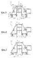
- the optical instrument 10 shown in FIGS. 1 to 4 is intended for the observation of the skin P or the hair and comprises a support 11 to be placed on the surface to be observed, a mobile assembly 12 that can be moved relative to the support 11 along an axis X, and a handle 13 allowing the gripping of the instrument by a user, this handle 13 being fixed relative to the support 11 and housing internally one or more batteries or accumulators 14.
- An elastic return system interacts between the support 11 and the assembly movable 12, so as to recall the latter in a rest position, corresponding to FIG. 1, in which the assembly 12 bears against the handle 13.
- this return system comprises several springs 15 while working in compression, bearing at one end against a shoulder of the support 11 and at the other end against the assembly 12.
- the latter comprises a plurality of light emitters 17 constituted, in the example described, by white light-emitting diodes distributed all around the X axis, as shown in FIG. 2, so as to produce either a diffuse illumination of the Z zone examined when all the light emitters are powered, ie a light in one or more particular directions, if only part of the transmitters bright is powered.
- the light emitters 17 are supplied with electricity thanks to to the batteries 14 by a supply circuit 30, shown very schematically, in a concern for clarity of the drawing. This supply circuit 30 is connected to a control circuit 31.
- An optical element 23 is placed on the path of light between the emitters 17 and the zone examined Z.
- This optical element 23 is constituted in the example considered by a translucent annular piece, which may be colorless or colored, and which constitutes a broadcaster.
- the tube 18 is extended below by a screen 27, whose free edge 28 delimits the field of observation.
- the optical instrument 10 makes it possible to carry out successive observations, in different lighting conditions, from the same surface.
- the examined zone Z can be diffusely and omnidirectionally lit by all light emitters 17.
- the screen 27 can be brought closer to the examined zone Z thanks to the mobility of the assembly 12 relative to the support 11, as shown in Figure 3.
- the lower edge 28 of the screen 27 could be moved closer by the user exerting a sufficient downward pressure on the assembly 12, against the recall action 15. It is then possible to obtain a lighting grazing of the zone examined Z, capable of to bring out more the relief of the skin or the hair and to increase the shine.
- the user can also fully press the assembly 12 so as to bring the screen 27 in contact with the surface of the skin or hair, as shown in Figure 4.
- the examined area Z is illuminated only by transillumination, ie by diffusion of light into the tissue observed, which makes it possible, for example, to obtain information on its transparency, color or its irrigation by the blood. Power supply of light emitters 17 can remain unchanged between different observations.
- the control circuit 31 may consist of a simple switch electrical controlling all-or-nothing power of all transmitters 17 or by a more complex system, allowing for example to feed selectively certain light emitters 17, so as to obtain, for example, a lighting directional or multidirectional, fixed or rotating, or even in the case where transmitters luminaires would have diodes of different colors or capable of emitting variable wavelengths, to modify the spectral characteristics of the light illuminate the area examined.
- FIGS. 5 to 7 show an optical instrument 10 'which corresponds to to a variant of the instrument 10 described above.
- the instrument 10 ' comprises a body 16' which is fixed and a screen 27 'which is movable relative to the body 16' along the axis X, to modify the conditions of illumination of the observed zone Z, to allow for example to pass from multidirectional diffuse lighting to grazing lighting, as shown in Figure 6, even to transillumination illumination, as illustrated in FIG. 7.
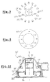
- a polarizer 23 'shown in isolation in FIG. 8 is placed on the path of the light between the light emitters 17 'and the observed zone Z.
- This polarizer 23' has an annular shape and a single polarization direction, indicated by arrows in Figure 8.
- the screen 27 ' is slidably mounted on a tube 18' which supports lenses 20 ', 21' and polarizers 24 ', 25' and can be moved by means of a protruding tab 30 ' outside the instrument, passing through a slot 31 'of the body 16', on which are mounted the light emitters 17 '. These are arranged in the same way as the light emitters 17 of the previous set.
- An advantage of the instrument 10 ' do not change the distance between the examined area and the lenses 20 ', 21' during change of configuration of the lighting by moving the screen 27 '.
- two polarisers 24 'and 25' each shaped half disc and joined by their base so as to form an analyzer disc, are placed in the path of light in the tube 18 ', in the image focal plane of the lens 20'.
- the Polarization directions of the polarizers 24 'and 25' are perpendicular to each other and indicated by arrows in Figure 9.
- the analyzer constituted by the polarizers 24 'and 25' makes it possible to obtain a half-image with brilliance and half-image without brilliance, choosing the direction of polarization of one of the half-discs 24 'and 25' parallel to the direction of polarization of the polarizer 23 '.
- the polarizers 24 'and 25' are replaced by a polarizer rotatably mounted about the X axis so that it can coincide with its direction of polarization with the direction of polarization of incident light and secondly then direct its direction of polarization perpendicular to the direction of polarization of the polarizer 23 '.
- the two-part analyzer 24 ', 25' makes it possible to obtain an image contrast, and therefore to take advantage of the increased sensitivity of the human eye to a contrast.
- This window 35 can be made of plastic for example, and have a rim 36 allowing its positioning on the instrument.
- the window 35 constitutes a removable accessory but it is not beyond the scope of the present invention when the window is retractable and remains attached to the instrument in its retracted position. when is in place on the instrument, the window 35 compresses the skin and expels the blood ; we can thus make observations of the skin by decreasing the incidence of the color of the blood on the color of the skin.
- a series of observations can be made without the window 35, then to a new series of observations with the window 35, under different types of lighting or polarizations and compare the results to draw a useful information.
- FIGS. 11, 13 and 14 show an instrument 40, one of which particularity, compared to the instruments 10 and 10 'previously described, is to have no built-in lighting
- the instrument 40 comprises a body 41 extended downwards by a skirt transparent 42.
- the body 41 serves as support for an optical assembly comprising lenses 43, 44 carried by a tube 45, snapped into the body 41.
- the optical assembly comprises also a reticle 46 for measuring a distance on the examined area. This the reticle is printed, in the example described and shown separately in FIG. glass 47 placed on the path of light from the area examined.
- a colored filter 46 is removably mounted on the body 41.
- this filter is blue, so as to highlight, if desired, the pigmentary spots.
- a screen consisting of an opaque ring 48 can slide on the body 41 and on the transparent skirt 42, between a completely retracted position, corresponding to FIG. 11, in which the ring 48 does not cover the transparent skirt 42, a intermediate position corresponding to Figure 13, in which the ring 48 comes cover a major part of the transparent skirt 42, to allow illumination shaving the area examined, and a fully lowered position of the ring 48 corresponding to Figure 14, in which the latter completely covers the skirt transparent 42 and allows illumination by transillumination.
- flutes 49 and 50 are formed on the body 41 and the transparent skirt 42 so as to allow immobilization of the ring 48 in each of the different configurations described.
- the observer can measure by means of the reticle the distance from which the diffusion of the light is no longer visible and draw information on the transparency of the skin.
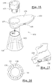
- FIG. 15 shows another example of an observation device 120 made according to the invention.
- This device 120 comprises a light source 122, a tip 123, and a optical assembly 121.
- the light source 122 comprises a handle 124 which forms a housing to inside which are arranged one or more batteries or accumulators, and a part openwork 127 in which can be engaged the optical assembly 121.
- the latter has an eyepiece 128 and one or more lenses represented, so as to produce an enlarged image, as well as a polarizer.
- the light source 122 comprises a selector 126 making it possible to illuminate the area to be observed with for example two different light intensities or two types different lighting, for example one simulating daylight and the other lighting incandescent.
- the tip 123 has a generally frustoconical shape with a base 129 having a diameter greater than the field of view of the optical assembly 121.
- the diameter of the base 129 is of the order of 40 mm and that of the field of view of the order of 30 mm. This avoids the pressure of contact of the tip 123 on the skin influences the appearance of the zone located in the field observation.
- the tip 123 may for example comprise a magnetic ring metal.
- the tip 123 may have at its end that comes into contact with the skin a removable ring.
- the light source 122 comprises, as can be seen in FIG. a plurality of electroluminescent diodes 130 whose axis is substantially parallel to that of the optical assembly 121. These light emitting diodes 130 are covered by a polarizer 131.
- the height of the nozzle 123 is chosen so that the lighting of the skin area located in the field of view is substantially homogeneous.
- the optical assembly 121 comprises two juxtaposed polarizers having perpendicular directions of polarization, as in the case of the embodiment described above, with reference to FIG. 9.
- the device 120 may comprise, as illustrated in FIG. 133 allowing the user to rotate the optical assembly 121 with the hand who holds the handle 124.
- Each image observed by means of an optical instrument for example one of those just described, this observation having taken place under conditions of specific illumination, can be compared with a reference image of an atlas containing several reference images, for example images expressing various degrees a characteristic of the body typology, especially the brilliance or the skin color, or images corresponding to varying degrees of contrast.
- a gloss atlas comprising several reference images 60 corresponding each to a degree of shine of the skin, quantified by an identifier alphanumeric 61.
- FIG. 19 shows very schematically an atlas of contrast or differences in brightness or color, with several images of reference 70, corresponding to different degrees of contrast or deviation that can be observed when using an analyzer such as that formed by the half-discs 24 ', 25 ', previously described. These images 70 are associated with identifiers alphanumeric 71, to identify them.
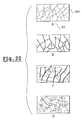
- FIG. 20 very schematically shows an atlas of cutaneous dryness, comprising several images 80, each associated with an identifier alphanumeric 81, the 80 images expressing various degrees of cutaneous dryness, ranging severe desquamation, characteristic of extremely dry skin, absence desquamation, translating normal skin.
- the reference images of an atlas can be printed on the same support or be connected together, as shown in Figure 21.
- Reference images can also be displayed on the screen of a computer 110, as illustrated in FIG. 22, each image being associated with an identifier alphanumeric.
- the results of an evaluation can be transmitted remotely by a network computer, including the Internet, by means of the computer 110 to a server 100, as shown in FIG. 23.
- the server 100 can be arranged to make a diagnosis according to the results transmitted and, if necessary, to recommend a product cosmetic or care.
- these images can be transmitted by the server 100, after connection of the user on the corresponding website.
- the invention can be implemented so as to monitor the effectiveness of a treatment, carrying out an evaluation after each phase of treatment and comparing the results of successive evaluations.
- a bank of multivector data combining a set of vectors each corresponding to a individual, each vector having at least two components each constituted by the result of an observation made using the same optical instrument.
- observation devices which have just been described can be used in combination with a tool for wrinkling or stretching the skin.
- FIGS. 24 and 25 show an example of a tool 140 making it possible to wrinkle or stretch the skin.
- the tool 140 shown in these figures has two parts 141 and 142 intended to be applied to the skin and connected by a connection allowing a relative displacement of one relative to the other.
- each of the parts 141 and 142 has a shape of U and the two parts define between them, when close together, as one can see it in FIG. 25, a window 137 for observation of the skin, this window being formed by the concavities of the U.
- connection between the parts 141 and 142 can be achieved in various ways.
- the link comprises two rods 143 and 144 of axes parallel.
- the rod 143 is fixed at one end in the portion 142 and can slide in a housing of the portion 141.
- the rod 143 has at its opposite end a head widened 145, connecting to the rest of the rod forming a groove 146.
- the rod 143 also comprises a second groove 147 and the portion 141 comprises a ball 148, biased by a spring 149 bearing against the rod 143.
- each ball 148 comes engage in the corresponding groove 146 which allows to immobilize the two parts 141 and 142 in their separated position.
- each ball 148 engages in the groove 147 corresponding.
- the tool 140 can be positioned on the skin by disposing an adhesive tape double-sided on each of the parts 141 and 142.
- the observation device can be configured to cooperate with the tool 140.
- the tool 140 may advantageously be provided, as illustrated in FIGS. 26 and 27, at least one elastic member constituted by example of a coil spring 150 engaged on one of the rods.
- Each rod 143 or 144 can be provided with its corresponding spring 150.
- the spring 150 can, as illustrated in FIG. 26, bear on one end against a ring 151 attached to one of the parts intended to be applied to the skin and come to bear on the other end against a shoulder 152 of the rod.
- the spring 150 is in the compressed state when the two parts 141 and 142 are close together.
- the tool can be placed on the skin while the parts 141 and 142 are brought together, each spring 150 being compressed then the parts 141 and 142 can deviate under the effect of the relaxation of the springs 150.
- At least one of the rods 143 or 144 may comprise graduations 153 which become apparent when parts 141 and 142 deviate, allowing precisely determine the spacing between the two parts 141 and 142.
- At least one elastic member arranged differently, for example a coil spring 160 working in compression, engaged on one of the rods 143 and 144, whose ends support in the bottom of housing 161 and 162 facing each other parts 141 and 142, these housings being made for example in the branches of the U, as illustrated in FIG. Figure 28.
- the device of Figure 28 may allow, where appropriate, to retain the grooves 146, 147 and the balls 148 of the example of FIGS. 24 and 25.
- the invention is not limited to the examples that have just been described and the structure of the optical instrument can be modified, particularly in replacing the light-emitting diodes by other means of illumination, such as by example of incandescent or fluorescent lamps.
- this screen can be constituted by an element attached, removably attached to the optical instrument.
Abstract
Description
La présente invention est relative à l'évaluation de caractéristiques de la typologique corporelle, notamment des caractéristiques d'apparence telles que la brillance, la couleur et le relief cutané, par exemple.The present invention relates to the evaluation of characteristics of the body typology, including appearance characteristics such as shine, color and skin relief, for example.
Il existe des dermatoscopes qui contiennent un système de grossissement et des moyens d'éclairage intégrés permettant de faire des observations précises. Toutefois, ces dermatoscopes ne sont pas prévus pour délivrer une image autre qu'un simple agrandissement de la zone observée. De plus, les caractéristiques de l'éclairage sont susceptibles de varier d'un dermatoscope à l'autre, ce qui n'est pas trop gênant lorsqu'il s'agit d'observer un défaut de la peau mais n'est pas satisfaisant lorsqu'il s'agit d'évaluer des caractéristiques d'apparence telles que la brillance ou la couleur, par exemple.There are dermatoscopes that contain a magnification system and integrated lighting means making it possible to make precise observations. However, these dermatoscopes are not intended to deliver an image other than a simple enlargement of the observed area. In addition, the lighting characteristics are likely to vary from one dermatoscope to another, which is not too troublesome when is to observe a skin defect but is unsatisfactory when it comes to evaluating appearance characteristics such as gloss or color, for example.
Des systèmes complexes utilisant des caméras vidéo ou d'autres capteurs électroniques existent par ailleurs, étant décrits par exemple dans la demande de brevet EP-A-0 655 221 ou le brevet US 5 377 000. Ces systèmes sont relativement coûteux et se prêtent mal à une large diffusion afin d'équiper par exemple tous les points de vente d'un produit ou de permettre au public de s'évaluer lui-même.Complex systems using video cameras or other sensors electronic devices exist, for example described in the patent application EP-A-0 655 221 or US Pat. No. 5,377,000. These systems are relatively expensive and do not lend themselves to wide distribution in order to equip for example all the outlets of a product or to allow the public to evaluate itself.
Il existe par conséquent un besoin pour bénéficier d'un instrument simple à utiliser, relativement peu coûteux, permettant d'évaluer au moins une caractéristique d'apparence de la peau ou des cheveux, par exemple des caractéristiques liées à l'éclat du teint ou à l'éclat des cheveux, telles que la brillance et la couleur.There is therefore a need to benefit from a simple instrument to use, relatively inexpensive, to evaluate at least one characteristic appearance of the skin or hair, for example characteristics related to the brightness of the skin complexion or shine, such as shine and color.
L'invention vise notamment, selon un de ses aspects, à répondre à ce besoin.The invention aims in particular, according to one of its aspects, to meet this need.
Elle y parvient grâce à un nouveau dispositif d'observation portatif permettant d'évaluer au moins une caractéristique de la typologie corporelle, notamment une caractéristique d'apparence de la peau et/ou des cheveux, ce dispositif pouvant se caractériser par le fait, selon l'un des aspects de l'invention, qu'il permet d'observer directement une zone de la peau ou des cheveux et comporte des moyens permettant de générer au moins deux images d'une zone examinée qui diffèrent autrement que par le grossissement ou l'intensité lumineuse d'une source intégrée.It achieves it with a new portable observation device to evaluate at least one characteristic of the body typology, in particular an appearance characteristic of the skin and / or hair, this device being able to characterize, according to one aspect of the invention, that it makes it possible to observe directly to an area of the skin or hair and includes means for generate at least two images of an examined area that differ in different ways from the magnification or light intensity of an integrated source.
Lesdites images peuvent être générées de manière à pouvoir être comparées entre elles, soit simultanément, soit successivement.Said images can be generated so that they can be compared between them, either simultaneously or successively.
Lesdites images peuvent être générées successivement en agissant entre les deux observations sur un organe du dispositif permettant de faire varier une caractéristique autre que le grossissement ou l'intensité lumineuse de la source.Said images can be generated successively by acting between two observations on an organ of the device to vary a characteristic other than the magnification or luminous intensity of the source.
Lesdites images peuvent aussi être générées simultanément lorsque le dispositif est agencé pour produire simultanément, avec des éléments optiques, deux images différentes de la zone observée.Said images can also be generated simultaneously when the device is arranged to simultaneously produce, with optical elements, two different images of the observed area.
Lesdites images peuvent différer par exemple par l'orientation d'une direction de polarisation d'un analyseur, par le degré de directivité de la lumière incidente, par la direction d'incidence de la lumière incidente, par la couleur de la lumière, par le filtrage de la lumière provenant de la zone examinée, ou encore par une action mécanique exercée sur la zone examinée, par exemple une pression, un plissement ou un étirement.Said images may differ for example by the orientation of a direction polarization of an analyzer, by the degree of directivity of the incident light, by the direction of incidence of incident light, by the color of light, by filtering light from the area under examination, or by mechanical action exerted on the examined area, such as pressure, wrinkling or stretching.
Lesdites images peuvent être ou non générées pour suivre l'évolution d'une zone examinée au cours du temps.Said images may or may not be generated to follow the evolution of a area examined over time.
Le dispositif d'observation peut permettre de suivre l'évolution d'une zone de peau au cours du temps, en générant à un instant donné au moins deux images de la zone de peau, différant autrement que par le grossissement ou l'intensité lumineuse d'une source intégrée, et en générant, par exemple un mois plus tard, au moins deux images de la même zone de peau, différant autrement que par le grossissement ou l'intensité lumineuse d'une source intégrée.The observation device can make it possible to follow the evolution of a zone of skin over time, generating at a given moment at least two images of the area skin, differing only in the magnification or luminous intensity of a skin integrated source, and generating, for example a month later, at least two images of the same skin area, differing only in magnification or intensity of an integrated source.
Le dispositif selon l'invention permet une observation directe, c'est-à-dire en regardant au travers du dispositif d'observation la zone examinée, sans acquisition par un appareil photographique, une caméra vidéo ou d'autres types de capteurs électroniques. Son coût de production peut ainsi rester compatible avec une large diffusion.The device according to the invention allows direct observation, that is to say in looking through the observation device the examined area, without acquisition by a camera, a video camera or other types of electronic sensors. Its cost of production can thus remain compatible with a wide diffusion.
Par ailleurs, l'observation pouvant s'effectuer dans des conditions d'illumination prédéfinies, il est possible de quantifier la caractéristique observée d'une manière relativement précise et reproductible.Moreover, the observation can be made under conditions predefined illumination, it is possible to quantify the observed characteristic of a relatively accurate and reproducible way.
Dans une réalisation particulière, le dispositif comporte un système optique agencé pour produire une image agrandie de la zone examinée. Il est ainsi possible d'évaluer des caractéristiques de la peau difficiles à observer à l'oeil nu, telles que par exemple sa desquamation.In a particular embodiment, the device comprises an optical system arranged to produce an enlarged image of the examined area. It is thus possible to evaluate skin characteristics that are difficult to see with the naked eye, such as example its desquamation.
Toujours dans une réalisation particulière, le dispositif est agencé pour permettre de réduire ou d'éliminer la brillance d'une partie au moins de la zone examinée, ce qui peut permettre par exemple d'observer plus facilement la couleur de la peau ou des cheveux, sans être gêné par des reflets. La suppression ou la diminution de la brillance peut également être utile pour observer la couleur de la lumière qui est rétrodiffusée, provenant des couches profondes de l'épiderme ou des cheveux, et qui dépend de l'état de ces couches. Il peut notamment être intéressant d'observer le contraste entre la lumière qui comporte une composante de réflexion et une composante rétrodiffusée et la lumière qui comporte essentiellement une composante rétrodiffusée, en éclairant par exemple la zone examinée avec une lumière polarisée et en observant avec un analyseur. Ce dernier peut comporter un polariseur rotatif ou deux polariseurs ayant des directions de polarisation différentes, dont l'une peut être perpendiculaire à la direction de polarisation de la lumière incidente et l'autre parallèle.Still in a particular embodiment, the device is arranged to to reduce or eliminate the brightness of at least part of the area examined, which may make it easier, for example, to observe the color of the skin or hair, without being bothered by reflections. The deletion or decrease of brilliance can also be helpful in observing the color of light that is backscattered, from deep layers of the epidermis or hair, and depends on the state of these layers. It may be interesting to observe the contrast between light that has a reflection component and a component backscattered light and the light which essentially comprises a backscattered component, in illuminating for example the examined area with polarized light and observing with an analyzer. The latter may comprise a rotary polarizer or two polarizers having different polarization directions, one of which may be perpendicular to the direction of polarization of the incident light and the other parallel.
Dans une réalisation particulière, la zone examinée peut être éclairée à l'aide d'un moyen d'éclairage permettant de l'illuminer avec des inclinaisons différentes de la lumière incidente, afin par exemple de l'observer sous éclairage diffus ou sous éclairage rasant.In a particular embodiment, the examined area can be illuminated using a lighting means for illuminating it with different inclinations of the incident light, for example to observe it under diffuse lighting or under lighting shaving.
On peut disposer ainsi de plusieurs conditions d'observation, ce qui peut permettre d'évaluer plus facilement une caractéristique d'apparence, en faisant ressortir les différences entre deux images, par exemple.We can thus have several observation conditions, which can make it easier to evaluate an appearance characteristic, highlighting the differences between two images, for example.
L'éclairage rasant peut donner des informations de relief et l'éclairage diffus des informations sur l'homogénéité de la couleur.Shading lighting can give relief information and diffused lighting information on the homogeneity of the color.
Dans une réalisation particulière, le dispositif comporte au moins un écran apte à être interposé entre une source de lumière et la zone examinée, de manière à ne permettre l'éclairage de cette dernière que par diffusion de la lumière sous l'écran, dans le tissu examiné. Cet écran peut être mobile, pouvant être déplacé d'une première position dans laquelle il est éloigné d'une surface bordant la zone examinée à une deuxième position dans laquelle il vient au contact de ladite surface. On peut ainsi observer la peau ou les cheveux par transillumination, c'est-à-dire que l'éclairage d'une zone de peau ou de cheveux s'effectue par la lumière provenant de zones adjacentes, la peau ou les cheveux servant de guide de lumière, et obtenir notamment une information de transparence, cette information pouvant se combiner le cas échéant à d'autres informations tirées d'observations précédentes ayant eu lieu dans des conditions d'illumination différentes. L'écran peut encore être amené dans une position dans laquelle il permet un éclairage rasant de la zone examinée. L'écran peut comporter une paroi tubulaire s'étendant, au cours de l'utilisation, autour de la zone examinée. L'écran, qui peut être de section non circulaire, peut comporter une portion conique ou pyramidale convergeant vers la zone examinée. Le dispositif peut comporter au moins un ressort pour rappeler l'écran dans une position de repos, en l'absence d'utilisation.In a particular embodiment, the device comprises at least one screen able to be interposed between a light source and the examined area, so as not to allow lighting of the latter only by diffusion of light under the screen, in the examined tissue. This screen can be mobile, movable from a first position in which it is removed from a surface bordering the examined area to a second position in which it comes into contact with said surface. We can thus observe the skin or hair by transillumination, that is to say that the illumination of a zone of skin or hair is made by light from adjacent areas, skin or hair used as a light guide, and in particular to obtain transparency information, this information which may be combined, where appropriate, with other information previous observations that occurred under different illumination conditions. The screen can still be brought into a position in which it allows illumination shaving the area examined. The screen may comprise a tubular wall extending, at during use, around the area examined. The screen, which may be of non-section circular, may have a conical or pyramidal portion converging towards the zone examined. The device may comprise at least one spring to recall the screen in a rest position, in the absence of use.
Le dispositif peut comporter un réticule, permettant notamment de mesurer la distance à partir de laquelle la diffusion de la lumière n'est plus visible, lorsque l'on observe par transillumination.The device may comprise a reticle, in particular for measuring the distance from which the scattering of light is no longer visible, when one observed by transillumination.
Dans une réalisation particulière, le dispositif comporte au moins un filtre coloré. Ce filtre peut être de couleur bleue, afin de faire ressortir la pigmentation de la peau, par exemple.In a particular embodiment, the device comprises at least one filter colored. This filter can be blue in order to highlight the pigmentation of the skin, for example.
Dans une réalisation particulière, le dispositif comporte au moins un polariseur. Ce polariseur peut être placé sur le trajet de la lumière, entre une source de lumière et la zone examinée. Le dispositif peut également comporter au moins un polariseur placé sur le trajet de la lumière entre la zone examinée et un oeil de l'observateur. Le dispositif peut comporter au moins deux polariseurs d'orientations différentes, juxtaposés, placés sur le trajet de la lumière entre la zone examinée et un oeil de l'observateur. On peut ainsi observer un contraste entre deux zones de l'image, et profiter de la sensibilité plutôt élevée de l'oeil humain à un contraste. Le dispositif peut comporter au moins un polariseur monté rotatif de manière à permettre à l'utilisateur de modifier l'orientation de sa direction de polarisation par rapport à une direction de référence. Dans ce dernier cas, le dispositif peut comporter par exemple une poignée comportant un organe d'actionnement tel qu'une molette par exemple, permettant de modifier l'orientation du polariseur avec la même main que celle qui tient la poignée.In a particular embodiment, the device comprises at least one polarizer. This polarizer can be placed on the path of light, between a source of light and the area examined. The device may also include at least one polarizer placed on the path of light between the examined area and an eye of the observer. The device may comprise at least two orientation polarizers different, juxtaposed, placed on the path of light between the examined area and an eye of the observer. It is thus possible to observe a contrast between two zones of the image, and enjoy the rather high sensitivity of the human eye to a contrast. The device can have at least one polarizer rotatably mounted so as to allow the user to change the orientation of its direction of polarization with respect to a direction of reference. In the latter case, the device may comprise for example a handle comprising an actuating member such as a wheel, for example, allowing change the orientation of the polarizer with the same hand that holds the handle.
Le dispositif peut être agencé pour permettre l'éclairage de la zone examinée par la lumière naturelle. Le dispositif peut notamment comporter une jupe en matière plastique transparente, dont un bord peut s'étendre autour de la zone examinée.The device can be arranged to allow illumination of the examined area by natural light. The device may in particular comprise a skirt made of transparent plastic, one edge of which may extend around the examined area.
Le dispositif peut aussi comporter au moins une source lumineuse intégrée. Cette source lumineuse intégrée peut comporter au moins un élément lumineux choisi parmi les suivants: lampe à incandescence, diode électroluminescente, lampe à fluorescence. Le dispositif peut comporter des éléments lumineux éclairant dans des gammes respectives de longueur d'onde différentes. Le dispositif peut par exemple comporter une source reproduisant les caractéristiques spectrales de la lumière naturelle, pouvant comporter des diodes électroluminescentes légèrement colorées. Le dispositif peut comporter plusieurs éléments lumineux et des moyens de commande permettant d'alimenter sélectivement au moins une partie de ces éléments lumineux. Le dispositif d'observation peut comporter des éléments lumineux disposés circulairement.The device may also include at least one integrated light source. This integrated light source may comprise at least one chosen light element among the following: incandescent lamp, light-emitting diode, fluorescent lamp fluorescence. The device may comprise lighting elements illuminating in respective ranges of different wavelengths. The device can for example have a source that reproduces the spectral characteristics of natural light, which may comprise slightly colored light-emitting diodes. The device may comprise a plurality of light elements and control means permitting selectively supplying at least a portion of these light elements. The device observation can include light elements arranged circularly.
Le dispositif peut encore comporter un logement pour recevoir une ou plusieurs piles électriques. Un tel logement peut présenter un axe sensiblement perpendiculaire à une direction d'observation de la zone examinée.The device may further comprise a housing for receiving one or several batteries. Such a housing may have a substantially perpendicular to a direction of observation of the area examined.
Le dispositif peut comporter une vitre permettant de comprimer la peau dans la zone examinée pour en chasser le sang. Une telle vitre peut être réalisée en verre ou en matière plastique transparente, éventuellement colorée. Une telle vitre peut constituer un accessoire amovible ou un élément fixé à demeure sur le dispositif, mobile entre une position active dans laquelle elle s'interpose entre la peau et le trajet de la lumière vers l'observateur et une position inactive, dans laquelle la vitre ne se situe pas sur le trajet de la lumière vers l'observateur.The device may comprise a window for compressing the skin in the area examined to expel the blood. Such a window may be made of glass or transparent plastic material, possibly colored. Such a window may constitute a removable accessory or an element permanently attached to the device, movable between a active position in which it interposes itself between the skin and the path of light towards the observer and an inactive position, in which the window is not on the path of the light towards the observer.
Le dispositif peut comporter une bague permettant l'adaptation d'un appareil photographique.The device may comprise a ring allowing the adaptation of a device photographic.
Dans une réalisation particulière, le dispositif est associé à un atlas comprenant une pluralité d'images de référence. Ces images peuvent être disposées sur un support unique ou être reliées ensemble. Les images peuvent être associées chacune à une indication alphanumérique.In a particular embodiment, the device is associated with an atlas comprising a plurality of reference images. These images can be arranged on a single support or be connected together. The images can each be associated with an alphanumeric indication.
Le dispositif peut également être associé à un ordinateur permettant d'afficher des images de référence.The device can also be associated with a computer for displaying reference images.
Le dispositif d'observation peut, par ailleurs, comporter ou être utilisé en combinaison avec un outil de plissement ou d'étirement de la peau.The observation device may, moreover, comprise or be used in combination with a tool for folding or stretching the skin.
Cet outil peut comporter, par exemple, deux parties destinées à être appliquées sur la peau et pouvant être écartées ou rapprochées pour étirer ou plisser la peau.This tool may include, for example, two parts intended to be applied to the skin and can be moved apart or together to stretch or skin.
L'outil peut comporter sur chaque partie destinée à être appliquée sur la peau une bande d'un adhésif double face lui permettant d'adhérer à la peau.The tool can have on each part intended to be applied to the skin a strip of a double-sided adhesive allowing it to adhere to the skin.
L'outil peut être fixé sur le dispositif d'observation.The tool can be attached to the observation device.
Au moins une différence entre les images observées au travers du dispositif d'observation peut être le degré de plissement ou d'étirement de la peau. At least one difference between the images observed through the device observation can be the degree of wrinkling or stretching of the skin.
L'outil de plissement ou d'étirement de la peau peut aussi être utilisé indépendamment du dispositif d'observation.The tool for folding or stretching the skin can also be used independently of the viewing device.
L'invention a ainsi pour objet, indépendamment du dispositif d'observation précité, un outil d'évaluation de la peau, comportant deux parties destinées à être appliquées sur la peau et reliées entre elles par une liaison permettant de les déplacer l'une par rapport à l'autre entre une position de pose de l'outil sur la peau, dans laquelle les deux parties sont rapprochées et une position d'étirement de la peau, dans laquelle les deux parties sont écartées, la liaison comportant au moins un organe élastique sollicitant les deux parties en écartement.The object of the invention is therefore, independently of the observation device mentioned above, a skin assessment tool consisting of two parts intended to be applied on the skin and connected to each other by a link allowing them to be moved relative to each other between a laying position of the tool on the skin, in which the two parts are close together and a position of stretching of the skin, in which the two parts are separated, the connection comprising at least one resilient member requesting the two parts apart.
Ainsi, les deux parties peuvent être rapprochées contre l'action de l'organe élastique puis posées sur la peau et relâchées. L'organe élastique peut les solliciter alors en écartement ou assister l'utilisateur qui les écarte manuellement.Thus, the two parts can be brought together against the action of the organ elastic and then placed on the skin and relaxed. The elastic member can solicit them then spread out or assist the user who manually bypasses them.
La liaison qui relie les deux parties peut être configurée de manière à permettre à l'utilisateur de les écarter d'une distance prédéterminée. La liaison peut comporter par exemple au moins une butée déterminant l'écartement maximal des deux parties. La liaison peut être configurée de manière à créer un point dur dans le déplacement des deux parties lorsque celles-ci atteignent leur écartement maximum. La liaison peut par exemple comporter au moins un organe de verrouillage qui s'enclenche lorsque l'écartement est maximal.The link that connects the two parts can be configured to allow the user to move them away from a predetermined distance. The link can for example comprise at least one stop determining the maximum spacing of the two parts. The link can be configured to create a hard point in the displacement of the two parts when they reach their maximum spacing. The connection may for example comprise at least one locking member which engages when the spacing is maximum.
Chacune des deux parties peut présenter par exemple une forme générale en U lorsque l'outil est observé de dessus, dans une direction perpendiculaire à la direction de déplacement relatif de deux parties.For example, each of the two parts may have a general form in U when the tool is viewed from above, in a direction perpendicular to the direction relative displacement of two parts.
Ces dernières peuvent être reliées entre elles par deux tiges, l'une des tiges étant fixée sur l'une des parties et l'autre tige fixée sur l'autre partie, chaque tige qui est fixée dans l'une des parties pouvant coulisser dans un logement de l'autre partie. Ce logement peut traverser une branche du U.These can be connected together by two rods, one of the rods being fixed on one of the parts and the other rod fixed on the other part, each rod which is fixed in one of the parts slidable in a housing of the other party. This housing can cross a branch of the U.
Les deux parties peuvent être configurées de manière à former entre elles, lorsqu'elles sont en position rapprochée, une fenêtre d'observation de la peau. Dans le cas où les deux parties présentent chacune une forme en U, cette fenêtre est formée par les deux concavités du U.Both parts can be configured to form between them, when in a close position, a window of observation of the skin. In the case where the two parts each have a U shape, this window is formed by the two concavities of the U.
Un matériau permettant de réaliser une empreinte, par exemple une cire ou une résine, peut être coulé dans la fenêtre précitée dans chacune des positions rapprochée ou écartée des deux parties de l'outil, par exemple afin de comparer l'aspect de la peau à l'état étiré ou non étiré à des intervalles de temps successifs.A material for making an impression, for example a wax or a resin, can be poured into the aforementioned window in each of the close positions or removed from both parts of the tool, for example to compare the appearance of the skin to the stretched or unstretched state at successive time intervals.
L'outil d'étirement de la peau peut être utilisé notamment pour faire apparaítre des microkystes ou d'autres défauts de la peau.The skin stretching tool can be used especially to make appear microcysts or other skin defects.
L'outil d'étirement peut encore être configuré de manière à permettre de mesurer l'écartement entre les deux parties appliquées sur la peau sous la seule action de l'organe élastique. Un écartement plus ou moins grand des deux parties peut traduire une capacité d'étirement plus ou moins grande de la peau. Dans le cas où la liaison entre les parties comporte des tiges comme défini plus haut, l'une des tiges précitée peut comporter des graduations permettant à l'utilisateur d'effectuer une mesure de l'écartement entre les deux parties.The stretching tool can still be configured to allow measure the distance between the two parts applied to the skin under the sole action of the elastic member. A greater or lesser separation of the two parts may ability to stretch more or less of the skin. In the case where the link between the parts has stems as defined above, one of the aforementioned stems may have graduations allowing the user to carry out a measurement of the distance between the two parts.
L'invention a encore pour objet un procédé dans lequel l'outil d'étirement défini ci-dessus est utilisé.The subject of the invention is also a method in which the stretching tool defined above is used.
Ce procédé peut comporter les étapes suivantes :
- disposer sur la peau un outil comportant deux parties d'application reliées par une liaison permettant de modifier leur écartement, ces deux parties étant par exemple mobiles en translation l'une par rapport à l'autre, ces deux parties étant de préférence solidarisées à la peau chacune au moyen d'un ruban adhésif double face, alors qu'elles sont dans une position rapprochée,
- écarter les deux parties pour provoquer un étirement de la zone de peau située entre elles.
- have on the skin a tool having two application parts connected by a connection to change their spacing, these two parts being for example movable in translation relative to each other, these two parts being preferably secured to the skin each with double-sided tape, while in a close position,
- separate the two parts to cause stretching of the skin area between them.
L'écartement des deux parties peut avoir lieu par exemple sous le seul effet d'au moins un organe élastique et/ou sous l'effet d'une action d'écartement d'un utilisateur.The separation of the two parts can take place for example under the sole effect of at least one elastic member and / or under the effect of a spreading action of a user.
Les deux parties peuvent être maintenues avec un écartement prédéterminé pendant l'observation de la peau.Both parts can be maintained with a predetermined spacing during the observation of the skin.
L'invention a encore pour objet un procédé pour évaluer le degré d'une caractéristique de la typologie corporelle, caractérisé par le fait qu'il comporte l'étape suivante :
- observer la peau ou les cheveux au moyen d'un dispositif d'observation tel que défini plus haut.
- observe the skin or hair by means of an observation device as defined above.
Les images observées peuvent être comparées avec des images de référence, afin de sélectionner l'une d'elles.The observed images can be compared with reference images, to select one of them.
Dans une mise en oeuvre particulière du procédé, on observe le contraste entre la lumière qui comporte une composante de réflexion et une composante rétrodiffusée et la lumière qui comporte essentiellement une composante rétrodiffusée, en éclairant la zone examinée avec une lumière polarisée et en l'observant avec un analyseur.In a particular implementation of the method, the contrast between light that has a reflection component and a backscattered component and light which has essentially a backscattered component, by illuminating the examined area with polarized light and observing it with an analyzer.
Les images de référence peuvent être affichées à l'écran d'un ordinateur, comme indiqué plus haut.Reference images can be displayed on the screen of a computer, as indicated above.
Les images de référence peuvent notamment être transmises à l'ordinateur depuis un serveur par un réseau informatique, avant d'être affichées sur ledit écran.The reference images can in particular be transmitted to the computer from a server via a computer network, before being displayed on said screen.
Le procédé peut comporter en outre l'étape consistant à transmettre au serveur une indication représentative de l'image de référence sélectionnée. Le serveur peut alors être programmé de manière à établir un diagnostic, par exemple, ou préconiser un produit cosmétique ou de soins.The method may further include the step of transmitting to server an indication representative of the selected reference image. The server can then be programmed to establish a diagnosis, for example, or to advocate a cosmetic or care product.
Dans une mise en oeuvre particulière de l'invention, on procède à une évaluation d'une caractéristique de la typologie corporelle, on effectue un traitement, notamment cosmétique, susceptible d'avoir une incidence sur ladite caractéristique, puis on procède à une nouvelle évaluation pour détecter une éventuelle évolution de ladite caractéristique et déterminer l'efficacité du traitement.In a particular embodiment of the invention, a method is evaluation of a characteristic of the body typology, we carry out a treatment, in particular cosmetic, which may have an effect on said characteristic, then a new evaluation is carried out to detect a possible evolution of the said characteristic and determine the effectiveness of the treatment.
Comme indiqué plus haut, on peut effectuer à l'aide du même dispositif
d'observation, successivement ou simultanément, au moins deux types d'observations,
choisis parmi les suivants :
Les types d'observation choisis peuvent notamment être i) et ii), v) et vi), vii) et viii), ix) et x) ou xi) et xii).The types of observation chosen may include (i) and (ii), (v) and (vi), (vii) and viii), ix) and x) or xi) and xii).
Dans le cas de l'observation selon ix) et x) ou xi) et xii), le procédé peut comporter l'étape consistant à, avant d'observer une zone de peau à l'aide du dispositif décrit plus haut, appliquer un outil d'étirement ou de plissement de la peau, par exemple un outil tel que défini précédemment, sur la zone de peau et étirer ou plisser la zone de peau.In the case of observation according to ix) and x) or xi) and xii), the process may comprise the step of, before observing a skin area using the device described above, apply a tool for stretching or wrinkling the skin, for example a tool as defined previously, on the skin area and stretch or wrinkle the area of skin.
L'invention a encore pour objet, selon un autre de ses aspects, un procédé pour évaluer le degré d'une caractéristique de la typologie corporelle, pouvant comporter les étapes suivantes :
- appliquer un outil d'étirement ou de plissement de la peau sur celle-ci,
- éventuellement prendre une empreinte de la zone de peau avant étirement ou plissement,
- étirer ou plisser la zone de peau,
- prendre une nouvelle empreinte de la zone de peau,
- observer la ou les empreintes ainsi obtenues à l'aide du dispositif d'observation défini plus haut.
- apply a tool for stretching or folding the skin on it,
- possibly take an impression of the skin area before stretching or folding,
- stretch or wrinkle the skin area,
- take a new imprint of the skin area,
- observe the fingerprint (s) thus obtained using the observation device defined above.
D'autres caractéristiques et avantages de la présente invention ressortiront à la lecture de la description détaillée qui va suivre, d'exemples non limitatifs de mise en oeuvre, et à l'examen du dessin annexé, sur lequel :
- la figure 1 représente de manière très schématique, en coupe axiale partielle, un instrument optique pour la mise en oeuvre de l'invention,
- la figure 2 est une vue partielle de dessus selon la flèche II de la figure 1, illustrant le positionnement des éléments lumineux,
- la figure 3 représente le dispositif de la figure 1 dans une configuration d'observation sous éclairage rasant,
- la figure 4 représente le dispositif de la figure 1 dans une configuration permettant une transillumination,
- la figure 5 est une coupe axiale, schématique et partielle, d'une variante du dispositif de la figure 1,
- la figure 6 représente le dispositif de la figure 5, dans une configuration permettant un éclairage rasant,
- la figure 7 représente le dispositif de la figure 5 dans une configuration permettant la transillumination,
- la figure 8 représente le polariseur du dispositif des figures 5 à 7, en vue de dessus,
- la figure 9 est une vue partielle de dessus, représentant le disque analyseur du dispositif des figures 5 à 7, et illustrant la disposition des émetteurs lumineux,
- la figure 10 représente une variante du dispositif des figures 5 à 7,
- la figure 11 représente, en coupe axiale schématique et partielle, un autre exemple d'instrument optique pour la mise en oeuvre de l'invention,
- la figure 12 est une vue partielle de dessus de la figure 11,
- la figure 13 représente le dispositif de la figure 11 dans une configuration d'éclairage rasant,
- la figure 14 représente le dispositif de la figure 11 dans une configuration permettant la transillumination,
- la figure 15 représente un autre exemple de dispositif, en perspective éclatée,
- la figure 16 est une vue partielle de face selon XVI de la figure 15,
- la figure 17 représente une variante d'une partie du dispositif de la figure 15,
- la figure 18 représente de manière très schématique un atlas de brillance,
- la figure 19 représente de manière très schématique un atlas de contrastes,
- la figure 20 représente de manière très schématique un atlas de sécheresse cutanée,
- la figure 21 illustre la réalisation d'un atlas sous la forme d'un ensemble d'images reliées,
- la figure 22 représente de manière schématique un ordinateur permettant d'afficher, sur un écran, des images de référence,
- la figure 23 illustre la connexion d'un ordinateur, sur lequel peuvent être affichées des images de référence, à un serveur distant,
- les figures 24 et 25 représentent en vue de dessus schématique un outil de plissement de la peau avec les parties d'application sur la peau respectivement en positions écartée et rapprochée,
- les figures 26 et 27 sont des coupes partielles d'un outil d'étirement de la peau, lorsque l'outil est en configuration de mise en place sur la peau et d'étirement de la peau, et
- la figure 28 représente partiellement une variante de l'outil des figures 24 à 27.
- FIG. 1 very schematically shows, in partial axial section, an optical instrument for implementing the invention,
- FIG. 2 is a partial view from above according to the arrow II of FIG. 1, illustrating the positioning of the light elements,
- FIG. 3 represents the device of FIG. 1 in an observation configuration under grazing light,
- FIG. 4 represents the device of FIG. 1 in a configuration allowing a transillumination,
- FIG. 5 is an axial section, schematic and partial, of a variant of the device of FIG. 1,
- FIG. 6 represents the device of FIG. 5, in a configuration allowing grazing illumination,
- FIG. 7 represents the device of FIG. 5 in a configuration allowing transillumination,
- FIG. 8 represents the polarizer of the device of FIGS. 5 to 7, seen from above,
- FIG. 9 is a partial view from above, representing the analyzer disc of the device of FIGS. 5 to 7, and illustrating the arrangement of the light emitters,
- FIG. 10 represents a variant of the device of FIGS. 5 to 7,
- FIG. 11 represents, in schematic and partial axial section, another example of an optical instrument for implementing the invention,
- FIG. 12 is a partial view from above of FIG. 11,
- FIG. 13 represents the device of FIG. 11 in a grazing lighting configuration,
- FIG. 14 represents the device of FIG. 11 in a configuration allowing transillumination,
- FIG. 15 represents another example of a device, in exploded perspective,
- FIG. 16 is a partial front view according to XVI of FIG. 15,
- FIG. 17 represents a variant of a part of the device of FIG. 15,
- FIG. 18 very schematically represents an atlas of brightness,
- FIG. 19 very schematically represents an atlas of contrasts,
- FIG. 20 very schematically represents an atlas of cutaneous dryness,
- FIG. 21 illustrates the production of an atlas in the form of a set of related images,
- FIG. 22 schematically represents a computer making it possible to display, on a screen, reference images,
- FIG. 23 illustrates the connection of a computer, on which reference images can be displayed, to a remote server,
- FIGS. 24 and 25 are a diagrammatic plan view of a tool for folding the skin with the application parts on the skin respectively in spaced apart and close positions,
- FIGS. 26 and 27 are partial sections of a skin stretching tool, when the tool is in the configuration of placement on the skin and stretching of the skin, and
- Figure 28 partially shows a variant of the tool of Figures 24 to 27.
L'instrument optique 10 représenté sur les figures 1 à 4 est destiné à
l'observation de la peau P ou des cheveux et comporte un support 11 à poser sur la
surface à observer, un ensemble mobile 12 pouvant être déplacé par rapport au support 11
selon un axe X, et une poignée 13 permettant la préhension de l'instrument par un
utilisateur, cette poignée 13 étant fixe par rapport au support 11 et logeant intérieurement
une ou plusieurs piles ou accumulateurs 14.The
Un système de rappel élastique interagit entre le support 11 et l'ensemble
mobile 12, de manière à rappeler ce dernier dans une position de repos, correspondant à
la figure 1, dans laquelle l'ensemble 12 vient en appui contre la poignée 13. Dans
l'exemple illustré, ce système de rappel comporte plusieurs ressorts 15 en travaillant en
compression, venant en appui à une extrémité contre un épaulement du support 11 et à
l'autre extrémité contre l'ensemble 12.An elastic return system interacts between the
Ce dernier comporte une pluralité d'émetteurs lumineux 17 constitués, dans
l'exemple décrit, par des diodes électroluminescentes blanches, réparties tout autour de
l'axe X, comme illustré sur la figure 2, de manière à produire soit un éclairage diffus de
la zone Z examinée lorsque tous les émetteurs lumineux sont alimentés, soit un éclairage
dans une ou plusieurs directions particulières, si seulement une partie des émetteurs
lumineux est alimentée. Les émetteurs lumineux 17 sont alimentés en électricité grâce
aux piles 14 par un circuit d'alimentation 30, représenté très schématiquement, dans un
souci de clarté du dessin. Ce circuit d'alimentation 30 est relié à un circuit de commande
31.The latter comprises a plurality of
L'observation s'effectue au travers d'un tube 18 de l'ensemble mobile 12.The observation is made through a
Un élément optique 23 est placé sur le trajet de la lumière entre les émetteurs
lumineux 17 et la zone examinée Z. Cet élément optique 23 est constitué dans l'exemple
considéré par une pièce annulaire translucide, qui peut être incolore ou colorée, et qui
constitue un diffuseur. An
Le tube 18 est prolongé inférieurement par un écran 27, dont le bord libre 28
délimite le champ d'observation.The
L'instrument optique 10 permet d'effectuer des observations successives,
dans des conditions d'éclairage différentes, de la même surface.The
Dans la configuration représentée à la figure 1, la zone examinée Z peut être
éclairée de manière diffuse et omnidirectionnelle par la totalité des émetteurs lumineux
17.In the configuration shown in FIG. 1, the examined zone Z can be
diffusely and omnidirectionally lit by all
L'écran 27 peut être rapproché de la zone examinée Z grâce à la mobilité de
l'ensemble 12 par rapport au support 11, comme illustré sur la figure 3. Sur cette figure,
on voit que le bord inférieur 28 de l'écran 27 a pu être rapproché par l'utilisateur en
exerçant une pression suffisante vers le bas sur l'ensemble 12, contre l'action de rappel
des ressorts 15. On peut alors obtenir un éclairage rasant de la zone examinée Z, capable
de faire ressortir davantage le relief de la peau ou des cheveux et d'augmenter la brillance.The
L'utilisateur a également la possibilité d'appuyer complètement sur
l'ensemble 12 de manière à amener l'écran 27 au contact de la surface de la peau ou des
cheveux, comme illustré sur la figure 4. Dans ce cas, la zone examinée Z est éclairée
uniquement par transillumination, c'est-à-dire par diffusion de la lumière dans le tissu
observé, ce qui permet par exemple d'obtenir une information sur sa transparence, sa
couleur ou son irrigation par le sang. Le courant d'alimentation des émetteurs lumineux
17 peut rester inchangé entre les différentes observations.The user can also fully press
the
Le circuit de commande 31 peut être constitué par un simple interrupteur
électrique commandant l'alimentation en tout ou rien de la totalité des émetteurs
lumineux 17 ou par un système plus complexe, permettant par exemple d'alimenter
sélectivement certains émetteurs lumineux 17, afin d'obtenir par exemple un éclairage
directionnel ou pluridirectionnel, fixe ou tournant, voire dans le cas où les émetteurs
lumineux comporteraient des diodes de différentes couleurs ou capables d'émettre à des
longueurs d'ondes variables, pour modifier les caractéristiques spectrales de la lumière
venant éclairer la zone examinée.The
Conformément à l'invention, entre les différentes configurations d'observation de la zone examinée représentées sur les figures 1, 3 et 4, au moins une caractéristique d'observation autre que le grossissement ou l'intensité de la source lumineuse intégrée a été modifiée. According to the invention, between the different observation configurations of the examined area shown in FIGS. 1, 3 and 4, at least one characteristic other than the magnification or intensity of the integrated light source has been modified.
On a représenté sur les figures 5 à 7 un instrument optique 10' qui correspond
à une variante de l'instrument 10 décrit précédemment.FIGS. 5 to 7 show an optical instrument 10 'which corresponds to
to a variant of the
Dans cette variante, l'instrument 10' comporte un corps 16' qui est fixe et un écran 27' qui est mobile par rapport au corps 16' selon l'axe X, pour modifier les conditions d'illumination de la zone observée Z, afin de permettre par exemple de passer d'un éclairage diffus multidirectionnel à un éclairage rasant, comme illustré à la figure 6, voire à un éclairage par transillumination, comme illustré sur la figure 7.In this variant, the instrument 10 'comprises a body 16' which is fixed and a screen 27 'which is movable relative to the body 16' along the axis X, to modify the conditions of illumination of the observed zone Z, to allow for example to pass from multidirectional diffuse lighting to grazing lighting, as shown in Figure 6, even to transillumination illumination, as illustrated in FIG. 7.
Un polariseur 23' représenté isolément sur la figure 8 est placé sur le trajet de la lumière entre les émetteurs lumineux 17' et la zone observée Z. Ce polariseur 23' présente une forme annulaire et une direction de polarisation unique, indiquée par des flèches sur la figure 8.A polarizer 23 'shown in isolation in FIG. 8 is placed on the path of the light between the light emitters 17 'and the observed zone Z. This polarizer 23' has an annular shape and a single polarization direction, indicated by arrows in Figure 8.
L'écran 27' est monté coulissant sur un tube 18' qui supporte des lentilles
20', 21' et des polariseurs 24', 25' et peut être déplacé grâce à une patte 30' faisant saillie
à l'extérieur de l'instrument, traversant une fente 31' du corps 16', sur lequel sont montés
les émetteurs lumineux 17'. Ces derniers sont agencés de la même manière que les
émetteurs lumineux 17 de l'ensemble précédent. Un avantage de l'instrument 10' est de
ne pas modifier la distance entre la zone examinée et les lentilles 20', 21' lors du
changement de configuration de l'éclairage par déplacement de l'écran 27'.The screen 27 'is slidably mounted on a tube 18' which supports lenses
20 ', 21' and polarizers 24 ', 25' and can be moved by means of a protruding tab 30 '
outside the instrument, passing through a slot 31 'of the body 16', on which are mounted
the light emitters 17 '. These are arranged in the same way as the
Dans l'exemple considéré, deux polariseurs 24' et 25', en forme chacun de demi-disque et réunis par leur base de manière à former un disque analyseur, sont placés sur le trajet de la lumière dans le tube 18', dans le plan focal image de la lentille 20'. Les directions de polarisation des polariseurs 24' et 25' sont perpendiculaires entre elles et indiquées par des flèches sur la figure 9.In the example under consideration, two polarisers 24 'and 25' each shaped half disc and joined by their base so as to form an analyzer disc, are placed in the path of light in the tube 18 ', in the image focal plane of the lens 20'. The Polarization directions of the polarizers 24 'and 25' are perpendicular to each other and indicated by arrows in Figure 9.
L'analyseur constitué par les polariseurs 24' et 25' permet d'obtenir une demi-image avec brillance et une demi-image sans brillance, en choisissant la direction de polarisation de l'un des demi-disques 24' et 25' parallèle à la direction de polarisation du polariseur 23'.The analyzer constituted by the polarizers 24 'and 25' makes it possible to obtain a half-image with brilliance and half-image without brilliance, choosing the direction of polarization of one of the half-discs 24 'and 25' parallel to the direction of polarization of the polarizer 23 '.
Le cas échéant, les polariseurs 24' et 25' sont remplacés par un polariseur monté rotatif autour de l'axe X afin de pouvoir faire d'une part coïncider sa direction de polarisation avec la direction de polarisation de la lumière incidente et d'autre part orienter ensuite sa direction de polarisation perpendiculairement à la direction de polarisation du polariseur 23'. Where appropriate, the polarizers 24 'and 25' are replaced by a polarizer rotatably mounted about the X axis so that it can coincide with its direction of polarization with the direction of polarization of incident light and secondly then direct its direction of polarization perpendicular to the direction of polarization of the polarizer 23 '.
L'analyseur en deux parties 24', 25' permet cependant d'obtenir une image contrastée, et donc de profiter de la sensibilité accrue de l'oeil humain à un contraste.The two-part analyzer 24 ', 25', however, makes it possible to obtain an image contrast, and therefore to take advantage of the increased sensitivity of the human eye to a contrast.
Chaque instrument 10 ou 10' peut recevoir, comme illustré pour l'instrument
20' sur la figure 10, une vitre 35 à travers laquelle s'effectue l'observation. Cette vitre 35
peut être réalisée en matière plastique par exemple, et comporter un rebord 36 permettant
son positionnement sur l'instrument. Dans l'exemple considéré, la vitre 35 constitue un
accessoire amovible mais on ne sort pas du cadre de la présente invention lorsque la vitre
est escamotable et reste solidaire de l'instrument dans sa position escamotée. Lorsqu'elle
est en place sur l'instrument, la vitre 35 permet de comprimer la peau et d'en chasser le
sang ; on peut ainsi effectuer des observations de la peau en diminuant l'incidence de la
couleur du sang sur la couleur de la peau. On peut procéder à une série d'observations
sans la vitre 35, puis à une nouvelle série d'observations avec la vitre 35, sous différents
types d'éclairage ou de polarisations et comparer les résultats pour en tirer une
information utile.Each
On a représenté sur les figures 11, 13 et 14 un instrument 40 dont une
particularité, par rapport aux instruments 10 et 10' précédemment décrits, est de ne
comporter aucun éclairage intégré.FIGS. 11, 13 and 14 show an
L'instrument 40 comporte un corps 41 prolongé vers le bas par une jupe
transparente 42.The
Le corps 41 sert de support à un ensemble optique comportant des lentilles
43, 44 portées par un tube 45, encliqueté dans le corps 41. L'ensemble optique comporte
également un réticule 46 permettant de mesurer une distance sur la zone examinée. Ce
réticule est imprimé, dans l'exemple décrit et représenté isolément sur la figure 12, sur un
verre 47 placé sur le trajet de la lumière provenant de la zone examinée.The
Un filtre coloré 46 est monté de manière amovible sur le corps 41. Dans
l'exemple représenté, ce filtre est bleu, de manière à faire ressortir, si on le souhaite, les
tâches pigmentaires.A
Un écran constitué par une bague opaque 48 peut coulisser sur le corps 41 et
sur la jupe transparente 42, entre une position complètement escamotée, correspondant à
la figure 11, dans laquelle la bague 48 ne vient pas recouvrir la jupe transparente 42, une
position intermédiaire correspondant à la figure 13, dans laquelle la bague 48 vient
recouvrir une majeure partie de la jupe transparente 42, afin de permettre un éclairage
rasant de la zone examinée, et une position complètement descendue de la bague 48
correspondant à la figure 14, dans laquelle cette dernière recouvre en totalité la jupe
transparente 42 et permet un éclairage par transillumination. Dans l'exemple représenté,
des godrons 49 et 50 sont formés sur le corps 41 et la jupe transparente 42, de manière à
permettre l'immobilisation de la bague 48 dans chacune des différentes configurations
décrites.A screen consisting of an
Lorsque la zone examinée est observée par transillumination, l'observateur peut mesurer au moyen du réticule la distance à partir de laquelle la diffusion de la lumière n'est plus visible et en tirer une information sur la transparence de la peau.When the examined area is observed by transillumination, the observer can measure by means of the reticle the distance from which the diffusion of the light is no longer visible and draw information on the transparency of the skin.
On a représenté à la figure 15 un autre exemple de dispositif d'observation
120 réalisé conformément à l'invention.FIG. 15 shows another example of an
Ce dispositif 120 comporte une source lumineuse 122, un embout 123, et un
ensemble optique 121.This
La source lumineuse 122 comporte une poignée 124 qui forme un logement à
l'intérieur duquel sont disposées une ou plusieurs piles ou accumulateurs, et une partie
ajourée 127 dans laquelle peut être engagé l'ensemble optique 121.The
Ce dernier comporte un oculaire 128 et une ou plusieurs lentilles non
représentées, de manière à produire une image agrandie, ainsi qu'un polariseur.The latter has an
La source lumineuse 122 comporte un sélecteur 126 permettant d'éclairer la
zone à observer avec par exemple deux intensités lumineuses différentes ou deux types
d'éclairage différents, par exemple l'un simulant la lumière du jour et l'autre un éclairage
incandescent.The
L'embout 123 présente une forme générale tronconique avec une base 129
ayant un diamètre supérieur au champ d'observation de l'ensemble optique 121.The
Dans l'exemple illustré, le diamètre de la base 129 est de l'ordre de 40 mm et
celui du champ d'observation de l'ordre de 30 mm. On évite ainsi que la pression de
contact de l'embout 123 sur la peau influence l'aspect de la zone située dans le champ
d'observation.In the example illustrated, the diameter of the
On peut prévoir une fixation magnétique de l'embout sur la source lumineuse
122. L'embout 123 peut par exemple comporter un anneau aimanté métallique.It can provide a magnetic attachment of the tip on the
L'embout 123 peut comporter à son extrémité qui vient au contact de la peau
une bague amovible. The
La source lumineuse 122 comporte, comme on peut le voir sur la figure 16,
une pluralité de diodes électroluminescentes 130 dont l'axe est sensiblement parallèle à
celui de l'ensemble optique 121. Ces diodes électroluminescentes 130 sont recouvertes
par un polariseur 131.The
La hauteur de l'embout 123 est choisie de telle sorte que l'éclairage de la
zone de peau située dans le champ d'observation soit sensiblement homogène.The height of the
Le dispositif d'observation 120 s'utilise de la manière suivante :
Il est ainsi possible d'observer la peau successivement avec brillance et sans brillance.It is thus possible to observe the skin successively with brilliance and without shine.
Dans une variante de réalisation, l'ensemble optique 121 comporte deux
polariseurs juxtaposés ayant des directions de polarisation perpendiculaires, à l'instar de
l'exemple de réalisation décrit précédemment, en référence à la figure 9.In an alternative embodiment, the
Le dispositif 120 peut comporter, comme illustré à la figure 17, une molette
133 permettant à l'utilisateur d'entraíner en rotation l'ensemble optique 121 avec la main
qui tient la poignée 124.The
Chaque image observée au moyen d'un instrument optique, par exemple l'un de ceux qui viennent d'être décrits, cette observation ayant eu lieu dans des conditions d'illumination spécifiques, peut être comparée avec une image de référence d'un atlas comportant plusieurs images de référence, par exemple des images exprimant à des degrés divers une caractéristique de la typologie corporelle, notamment la brillance ou la couleur de la peau, ou des images correspondant à divers degrés de contraste.Each image observed by means of an optical instrument, for example one of those just described, this observation having taken place under conditions of specific illumination, can be compared with a reference image of an atlas containing several reference images, for example images expressing various degrees a characteristic of the body typology, especially the brilliance or the skin color, or images corresponding to varying degrees of contrast.
On a représenté de manière très schématique, à titre d'exemple, sur la figure
18, un atlas de brillance comportant plusieurs images de référence 60 correspondant
chacune à un degré de brillance de la peau, quantifié par un identifiant
alphanumérique 61.It is shown very schematically, by way of example, in the figure
18, a gloss atlas comprising
On a représenté de manière très schématique sur la figure 19 un atlas de
contraste ou d'écarts de luminosité ou de couleur, comportant plusieurs images de
référence 70, correspondant à différents degrés de contraste ou d'écart pouvant être
observés lors de l'utilisation d'un analyseur tel que celui formé par les demi-disques 24',
25', précédemment décrit. Ces images 70 sont associées à des identifiants
alphanumériques 71, permettant de les repérer.FIG. 19 shows very schematically an atlas of
contrast or differences in brightness or color, with several images of
On a représenté à la figure 20 de manière très schématique un atlas de
sécheresse cutanée, comportant plusieurs images 80, associées chacune à un identifiant
alphanumérique 81, les images 80 exprimant divers degrés de sécheresse cutanée, allant
d'une desquamation sévère, caractéristique d'une peau extrêmement sèche, à une absence
de desquamation, traduisant une peau normale.FIG. 20 very schematically shows an atlas of
cutaneous dryness, comprising
Les images de référence d'un atlas peuvent être imprimées sur un même support ou être reliées ensemble, comme illustré sur la figure 21.The reference images of an atlas can be printed on the same support or be connected together, as shown in Figure 21.
Des images de référence peuvent également être affichées à l'écran d'un
ordinateur 110, comme illustré à la figure 22, chaque image étant associée à un identifiant
alphanumérique.Reference images can also be displayed on the screen of a
Les résultats d'une évaluation peuvent être transmis à distance par un réseau
informatique, notamment le réseau Internet, au moyen de l'ordinateur 110 à un serveur
100, comme illustré à la figure 23. Le serveur 100 peut être agencé pour rendre un
diagnostic en fonction des résultats transmis et, le cas échéant, préconiser un produit
cosmétique ou de soins.The results of an evaluation can be transmitted remotely by a network
computer, including the Internet, by means of the
Dans le cas où des images de référence sont affichées sur l'écran d'un
ordinateur, ces images peuvent être transmises par le serveur 100, après connexion de
l'utilisateur sur le site Internet correspondant.In the case where reference images are displayed on the screen of a
computer, these images can be transmitted by the
L'invention peut être mise en oeuvre de manière à suivre l'efficacité d'un traitement, en procédant à une évaluation après chaque phase du traitement et en comparant les résultats des évaluations successives.The invention can be implemented so as to monitor the effectiveness of a treatment, carrying out an evaluation after each phase of treatment and comparing the results of successive evaluations.
Grâce à la possibilité d'obtenir au moyen d'un même instrument optique des informations de brillance, de couleur, de relief et de transparence, et grâce à l'utilisation d'un atlas permettant de quantifier ces informations, on peut constituer une banque de données multivectorielle regroupant un ensemble de vecteurs correspondant chacun à un individu, chaque vecteur comportant au moins deux composantes constituées chacune par le résultat d'une observation effectuée au moyen d'un même instrument optique.Thanks to the possibility of obtaining, by means of the same optical instrument, information of brightness, color, relief and transparency, and through the use of an atlas to quantify this information, a bank of multivector data combining a set of vectors each corresponding to a individual, each vector having at least two components each constituted by the result of an observation made using the same optical instrument.
Les dispositifs d'observation qui viennent d'être décrits peuvent être utilisés en combinaison avec un outil permettant de plisser ou d'étirer la peau.The observation devices which have just been described can be used in combination with a tool for wrinkling or stretching the skin.
On a représenté sur les figures 24 et 25 un exemple d'outil 140 permettant de
plisser ou d'étirer la peau.FIGS. 24 and 25 show an example of a
L'outil 140 représenté sur ces figures comporte deux parties 141 et 142
destinées à être appliquées sur la peau et reliées par une liaison permettant un
déplacement relatif de l'une par rapport à l'autre.The
Dans l'exemple illustré, chacune des parties 141 et 142 présente une forme
générale de U et les deux parties définissent entre elles, lorsque rapprochées, comme on
peut le voir sur la figure 25, une fenêtre 137 d'observation de la peau, cette fenêtre étant
formée par les concavités des U.In the illustrated example, each of the
La liaison entre les parties 141 et 142 peut être réalisée de diverses manières.The connection between the
Dans l'exemple considéré, la liaison comporte deux tiges 143 et 144 d'axes
parallèles.In the example under consideration, the link comprises two
La tige 143 est fixée à une extrémité dans la partie 142 et peut coulisser dans
un logement de la partie 141. La tige 143 présente à son extrémité opposée une tête
élargie 145, se raccordant au reste de la tige en formant une gorge 146. La tige 143
comporte également une deuxième gorge 147 et la partie 141 comporte une bille 148,
sollicitée par un ressort 149 en appui contre la tige 143.The
Il en est de même de la tige 144, qui est fixe par rapport à la partie 141 et qui
coulisse dans un logement de la partie 142.It is the same with the
Dans la position écartée des parties 141 et 142, chaque bille 148 vient
s'engager dans la gorge 146 correspondante ce qui permet d'immobiliser les deux parties
141 et 142 dans leur position écartée. Lorsque les parties 141 et 142 sont rapprochées,
chaque bille 148 s'engage dans la gorge 147 correspondante.In the separated position of
Cela permet de créer une sensation de point dur lorsque les deux parties sont en position écartée ou rapprochée.This creates a hard point sensation when both parts are in a remote or close position.
L'outil 140 peut être positionné sur la peau en disposant un ruban adhésif
double face sur chacune des parties 141 et 142.The
On peut procéder, au moyen de l'un des dispositifs d'observation décrits
précédemment, à deux observations, l'une lorsque la peau est non plissée, c'est-à-dire par
exemple dès que l'outil 140 a été posé sur la peau dans la position écartée représentée à la
figure 24, et l'autre après plissement de la peau, c'est-à-dire après que les parties 141 et
142 ont été rapprochées comme illustré sur la figure 25. Le dispositif d'observation peut
être configuré de manière à coopérer avec l'outil 140.One can proceed, by means of one of the described observation devices
previously, to two observations, one when the skin is not wrinkled, that is to say by
example as soon as the
On peut également procéder à une observation alors que la peau est à l'état
non étiré, c'est-à-dire après que l'outil 140 a été posé sur la peau alors que les parties 141
et 142 sont à l'état rapproché, comme illustré sur la figure 25, et à une observation
lorsque la peau est étirée, les parties 141 et 142 ayant été amenées dans la position écartée
représentée à la figure 24.We can also make an observation while the skin is in the state
not stretched, that is to say after the
Pour faciliter le passage de la position rapprochée représentée à la figure 25 à
la position écartée représentée à la figure 24, l'outil 140 peut être avantageusement muni,
comme illustré aux figures 26 et 27, d'au moins un organe élastique constitué par
exemple d'un ressort hélicoïdal 150 engagé sur l'une des tiges. Chaque tige 143 ou 144
peut être munie de son ressort 150 correspondant. Le ressort 150 peut, comme illustré à la
figure 26, prendre appui à une extrémité contre une bague 151 fixée sur l'une des parties
destinée à être appliquée sur la peau et venir en appui à l'autre extrémité contre un
épaulement 152 de la tige. Le ressort 150 est à l'état comprimé lorsque les deux parties
141 et 142 sont rapprochées. L'outil peut ainsi être posé sur la peau alors que les parties
141 et 142 sont rapprochées, chaque ressort 150 étant comprimé puis les parties 141 et
142 peuvent s'écarter sous l'effet de la détente des ressorts 150.To facilitate the transition from the close position shown in FIG.
the spaced apart position shown in FIG. 24, the
Au moins l'une des tiges 143 ou 144 peut comporter des graduations 153 qui
deviennent apparentes lorsque les parties 141 et 142 s'écartent, ce qui permet de
déterminer précisément l'écartement entre les deux parties 141 et 142.At least one of the
On pourrait bien entendu, sans sortir du cadre de la présente invention,
utiliser au moins un organe élastique disposé autrement, par exemple un ressort hélicoïdal
160 travaillant en compression, engagé sur l'une des tiges 143 et 144, dont les extrémités
viennent en appui dans le fond de logements 161 et 162 se faisant face des parties 141 et
142, ces logements étant réalisés par exemple dans les branches des U, comme illustré à
la figure 28.One could of course, without departing from the scope of the present invention,
use at least one elastic member arranged differently, for example a
Le dispositif de la figure 28 peut permettre, le cas échéant, de conserver les
gorges 146, 147 et les billes 148 de l'exemple des figures 24 et 25.The device of Figure 28 may allow, where appropriate, to retain the
Bien entendu, l'invention n'est pas limitée aux exemples qui viennent d'être décrits et l'on peut modifier la structure de l'instrument optique, notamment en remplaçant les diodes électroluminescentes par d'autres moyens d'éclairage, tels que par exemple des lampes à incandescence ou à fluorescence. Dans le cas où un écran serait utilisé pour observer par transillumination, cet écran peut être constitué par un élément rapporté, fixé de manière amovible sur l'instrument optique.Of course, the invention is not limited to the examples that have just been described and the structure of the optical instrument can be modified, particularly in replacing the light-emitting diodes by other means of illumination, such as by example of incandescent or fluorescent lamps. In the event that a screen is used to observe by transillumination, this screen can be constituted by an element attached, removably attached to the optical instrument.
Claims (51)
caractérisé par le fait qu'il comporte un système optique (20', 41' ; 44, 46 ; 121) agencé pour produire une image agrandie de la zone examinée.Device according to any one of the preceding claims,
characterized in that it comprises an optical system (20 ', 41'; 44, 46; 121) arranged to produce an enlarged image of the examined area.
Applications Claiming Priority (2)
| Application Number | Priority Date | Filing Date | Title |
|---|---|---|---|
| FR0109091 | 2001-07-09 | ||
| FR0109091A FR2826857B1 (en) | 2001-07-09 | 2001-07-09 | INSTRUMENT FOR OBSERVING SKIN OR HAIR |
Publications (2)
| Publication Number | Publication Date |
|---|---|
| EP1277436A1 true EP1277436A1 (en) | 2003-01-22 |
| EP1277436B1 EP1277436B1 (en) | 2009-12-02 |
Family
ID=8865283
Family Applications (1)
| Application Number | Title | Priority Date | Filing Date |
|---|---|---|---|
| EP02291574A Expired - Fee Related EP1277436B1 (en) | 2001-07-09 | 2002-06-25 | Instrument to observe the skin or hairs |
Country Status (7)
| Country | Link |
|---|---|
| US (1) | US7986987B2 (en) |
| EP (1) | EP1277436B1 (en) |
| JP (2) | JP4383024B2 (en) |
| CA (1) | CA2391595A1 (en) |
| DE (1) | DE60234555D1 (en) |
| ES (1) | ES2337771T3 (en) |
| FR (1) | FR2826857B1 (en) |
Cited By (4)
| Publication number | Priority date | Publication date | Assignee | Title |
|---|---|---|---|---|
| EP1523936A1 (en) | 2003-10-16 | 2005-04-20 | L'oreal | System for skin analysis |
| US8452384B2 (en) | 2003-10-03 | 2013-05-28 | MicroVision Medical Holdings B.V. | Systems and methods for sidesstream dark field imaging |
| US9131861B2 (en) | 2004-11-30 | 2015-09-15 | Academisch Medisch Centrum | Pulsed lighting imaging systems and methods |
| US10438356B2 (en) | 2014-07-24 | 2019-10-08 | University Health Network | Collection and analysis of data for diagnostic purposes |
Families Citing this family (53)
| Publication number | Priority date | Publication date | Assignee | Title |
|---|---|---|---|---|
| FR2831790B1 (en) * | 2001-11-06 | 2004-07-16 | Oreal | MEASUREMENT AND / OR ANALYSIS DEVICE OF AT LEAST ONE PARAMETER OF AN EXTERNAL PORTION OF THE HUMAN BODY |
| FR2833827B1 (en) * | 2001-12-21 | 2004-12-10 | Oreal | PROCESS FOR EVALUATING THE EYE CONTOUR REGION AND DEVICE FOR CARRYING OUT SUCH A METHOD |
| JP4216523B2 (en) * | 2002-04-25 | 2009-01-28 | スカラ株式会社 | unit |
| US7006223B2 (en) * | 2003-03-07 | 2006-02-28 | 3Gen, Llc. | Dermoscopy epiluminescence device employing cross and parallel polarization |
| US20050234526A1 (en) * | 2004-04-14 | 2005-10-20 | Gilhuly Terence J | Systems and methods for detection of disease including oral scopes and ambient light management systems (ALMS) |
| KR101142923B1 (en) * | 2004-04-20 | 2012-05-11 | 코닌클리케 필립스 일렉트로닉스 엔.브이. | Hair-detection device and hair-removing device comprising the same |
| JPWO2006049192A1 (en) * | 2004-11-05 | 2008-05-29 | ヤーマン株式会社 | Skin treatment equipment |
| US20060246020A1 (en) * | 2005-04-29 | 2006-11-02 | Cole Curtis A | Topical composition detection |
| ATE546294T1 (en) | 2005-08-12 | 2012-03-15 | Tcms Transparent Beauty Llc | SYSTEM AND METHOD FOR DELIVERING A REFLECTION MODIFICATION AGENT TO IMPROVE THE APPEARANCE OF HUMAN SKIN |
| US8942775B2 (en) * | 2006-08-14 | 2015-01-27 | Tcms Transparent Beauty Llc | Handheld apparatus and method for the automated application of cosmetics and other substances |
| US8184901B2 (en) | 2007-02-12 | 2012-05-22 | Tcms Transparent Beauty Llc | System and method for applying a reflectance modifying agent to change a person's appearance based on a digital image |
| US10486174B2 (en) * | 2007-02-12 | 2019-11-26 | Tcms Transparent Beauty Llc | System and method for applying a reflectance modifying agent electrostatically to improve the visual attractiveness of human skin |
| US10092082B2 (en) * | 2007-05-29 | 2018-10-09 | Tcms Transparent Beauty Llc | Apparatus and method for the precision application of cosmetics |
| JP5360352B2 (en) * | 2008-04-30 | 2013-12-04 | 花王株式会社 | Skin property measuring device |
| ES2715633T3 (en) | 2008-05-20 | 2019-06-05 | Univ Health Network | Device and method for imaging and fluorescence monitoring |
| JP5161011B2 (en) * | 2008-09-12 | 2013-03-13 | 花王株式会社 | Internal condition evaluation method and internal condition evaluation apparatus for hair |
| US20110075144A1 (en) * | 2009-09-25 | 2011-03-31 | Bossa Nova Technologies, Llc | Visual appearance measurement method and system for randomly arranged birefringent fibers |
| US8223322B2 (en) * | 2009-09-25 | 2012-07-17 | Bossa Nova Technologies, Llc | Visual appearance measurement method and system for randomly and regularly arranged birefringent fibers |
| FR2972109A1 (en) | 2011-03-04 | 2012-09-07 | Peritesco | METHOD FOR DETERMINING A STANDARDIZED LIGHTING FOR SURFACE CONDITION STUDY OF A SKIN AREA AND ASSOCIATED DEVICE |
| WO2012153695A1 (en) * | 2011-05-10 | 2012-11-15 | 国立大学法人豊橋技術科学大学 | Inspection device and inspection method using functional light source, and functional light source and design method therefor |
| US9693752B2 (en) * | 2011-06-21 | 2017-07-04 | Rescon Ltd | Non-resistive contact electrosonic sensor systems |
| JP5774930B2 (en) * | 2011-07-21 | 2015-09-09 | 日本電産コパル株式会社 | Skin observation device |
| JP5961265B2 (en) * | 2011-08-22 | 2016-08-02 | コーニンクレッカ フィリップス エヌ ヴェKoninklijke Philips N.V. | Hair treatment device with hair detector |
| US9057713B2 (en) | 2012-02-22 | 2015-06-16 | Rescon Ltd | Non-resistive contact electrical systems and methods for visualizing the structure and function of objects or systems |
| NL2008692C2 (en) * | 2012-04-24 | 2013-10-28 | Univ Delft Tech | A system and method for imaging body areas. |
| US9364684B2 (en) | 2012-06-22 | 2016-06-14 | S & Y Enterprises Llc | Aesthetic treatment device and method |
| JP6029379B2 (en) * | 2012-08-10 | 2016-11-24 | 花王株式会社 | Skin condition evaluation method and skin condition evaluation apparatus |
| DE202012008449U1 (en) | 2012-09-04 | 2012-09-20 | Heine Optotechnik Gmbh & Co Kg | Spacer attachment for a dermatoscope |
| JP5360449B2 (en) * | 2012-12-03 | 2013-12-04 | 花王株式会社 | Skin property measuring apparatus and method |
| US10617305B2 (en) * | 2013-02-28 | 2020-04-14 | Canfield Scientific, Incorporated | Dermatoscope devices |
| US9101320B2 (en) | 2013-04-09 | 2015-08-11 | Elc Management Llc | Skin diagnostic and image processing methods |
| US9256963B2 (en) | 2013-04-09 | 2016-02-09 | Elc Management Llc | Skin diagnostic and image processing systems, apparatus and articles |
| US9458990B2 (en) * | 2013-08-01 | 2016-10-04 | 3Gen, Inc. | Dermoscopy illumination device with selective polarization and orange light for enhanced viewing of pigmented tissue |
| GB2530055B (en) * | 2014-09-10 | 2017-05-10 | Coronet Medical Tech Ltd | Trephine guide |
| CN107920769B (en) * | 2015-08-27 | 2020-09-18 | 荷兰联合利华有限公司 | Handheld imaging device for measuring characteristics of hair and scalp |
| JP6855451B2 (en) | 2015-08-27 | 2021-04-07 | ユニリーバー・ナームローゼ・ベンノートシヤープ | Methods and systems for making product recommendations |
| KR101785056B1 (en) * | 2016-07-08 | 2017-11-06 | 주식회사 일루코 | Dermatoscope devices |
| RU2760377C2 (en) * | 2016-08-09 | 2021-11-24 | Конинклейке Филипс Н.В. | Apparatus and method for measuring the elasticity of skin |
| US11122206B2 (en) | 2016-11-08 | 2021-09-14 | Preh Holding, Llc | Personal care device with camera |
| US10511777B2 (en) | 2016-11-08 | 2019-12-17 | Thomas Nichols | Personal care device with camera |
| JP6965514B2 (en) * | 2016-12-21 | 2021-11-10 | 大日本印刷株式会社 | Observatory |
| EP3384829A1 (en) * | 2017-04-05 | 2018-10-10 | Koninklijke Philips N.V. | Skin gloss measurement for quantitative estimation of skin gloss |
| EP3384831A1 (en) * | 2017-04-05 | 2018-10-10 | Koninklijke Philips N.V. | Skin gloss measurement using brewster's angle |
| WO2019025175A1 (en) * | 2017-08-03 | 2019-02-07 | Kasprzak Michal Pawel | Dermoscope and methods |
| EP3479756A1 (en) | 2017-11-02 | 2019-05-08 | Koninklijke Philips N.V. | Optical skin sensor and method for optically sensing skin parameters |
| US10441379B2 (en) | 2017-12-28 | 2019-10-15 | 3Gen, Inc. | Multipurpose medical illuminator with magnification |
| EP3505048A1 (en) * | 2017-12-28 | 2019-07-03 | Koninklijke Philips N.V. | Optical skin sensor using optimal spectral bands to minimize the effect of probe pressure |
| JP7010265B2 (en) * | 2019-04-02 | 2022-01-26 | 花王株式会社 | Quantitative method of scales |
| US11140302B2 (en) * | 2019-04-09 | 2021-10-05 | Charles Hudson | Combined camera and wearable ring for holding a camera |
| KR102260260B1 (en) * | 2019-05-07 | 2021-06-03 | 주식회사 코드스콥 | Diagnostic Imaging System for Scalp Using Multi-Angle and wavelength Light Sources |
| US20200383631A1 (en) * | 2019-06-09 | 2020-12-10 | Canfield Scientific, Incorporated | Hair analysis methods and apparatuses |
| US11395714B2 (en) | 2019-11-11 | 2022-07-26 | Dermlite Llc | Medical illuminator with variable polarization |
| USD1000624S1 (en) | 2019-12-27 | 2023-10-03 | Thomas Nichols | Personal care device with camera |
Citations (3)
| Publication number | Priority date | Publication date | Assignee | Title |
|---|---|---|---|---|
| FR2650890A1 (en) * | 1989-08-09 | 1991-02-15 | Oreal | Apparatus intended to allow the evaluation of the brilliance of a surface, in particular of the skin |
| WO1996016698A2 (en) * | 1994-12-01 | 1996-06-06 | Artner, Norbert | Skin examination device |
| WO2001045557A1 (en) * | 1999-12-22 | 2001-06-28 | Xillix Technologies Corporation | Portable system for detecting skin abnormalities |
Family Cites Families (50)
| Publication number | Priority date | Publication date | Assignee | Title |
|---|---|---|---|---|
| US1339698A (en) * | 1919-05-15 | 1920-05-11 | Faix John | Combination-tool |
| US5311293A (en) | 1983-07-18 | 1994-05-10 | Chromatics Color Sciences International, Inc. | Method and instrument for selecting personal compatible colors |
| US5146923A (en) * | 1986-12-18 | 1992-09-15 | Dhawan Atam P | Apparatus and method for skin lesion examination |
| JPH01117756A (en) | 1987-10-30 | 1989-05-10 | Sadanari Nakano | Food comprising orange peel as main component |
| US4911544A (en) | 1987-11-13 | 1990-03-27 | Walsh John P | Skin condition analyzer for cosmetologists |
| JPH0365205A (en) | 1989-08-02 | 1991-03-20 | Mitsubishi Electric Corp | Bathtub water purification apparatus |
| JPH0719839B2 (en) | 1989-10-18 | 1995-03-06 | 株式会社東芝 | Method for manufacturing semiconductor substrate |
| JPH0722655Y2 (en) * | 1990-02-23 | 1995-05-24 | スカラ株式会社 | Skin observation device |
| FR2665959B1 (en) * | 1990-08-16 | 1994-01-14 | Oreal | APPARATUS FOR ASSESSING THE SHINE OF A SURFACE, PARTICULARLY SKIN. |
| JP3007978B2 (en) | 1990-12-11 | 2000-02-14 | スカラ株式会社 | Illumination mechanism for magnifying observation |
| JP2565679Y2 (en) | 1991-04-09 | 1998-03-18 | スカラ株式会社 | Observation device of simultaneous contrast type of heterogeneous image and composite filter used therefor |
| US6485413B1 (en) * | 1991-04-29 | 2002-11-26 | The General Hospital Corporation | Methods and apparatus for forward-directed optical scanning instruments |
| JP2745870B2 (en) | 1991-07-11 | 1998-04-28 | 株式会社島津製作所 | Skin analyzer |
| JPH0771945A (en) | 1992-08-07 | 1995-03-17 | Kao Corp | Method and device for measuring surface shape |
| JPH0695996A (en) | 1992-09-14 | 1994-04-08 | Ricoh Co Ltd | Information processing system |
| US5377000A (en) | 1993-04-29 | 1994-12-27 | Color And Appearance Technology, Inc. | Portable appearance measuring apparatus |
| JPH0722655A (en) | 1993-06-29 | 1995-01-24 | Aisin Seiki Co Ltd | Thermoelectric transducer |
| JP3219551B2 (en) | 1993-06-30 | 2001-10-15 | 株式会社資生堂 | Surface condition analysis system |
| JPH07143967A (en) | 1993-09-29 | 1995-06-06 | Kao Corp | Method and apparatus for measuring light transmissivity of skin |
| NL9302043A (en) | 1993-11-25 | 1995-06-16 | Recticel Nederland Bv | Two-piece core mattress with taper towards the center. |
| FR2712985B1 (en) | 1993-11-26 | 1996-01-26 | Oreal | Colorimetric measuring head, and method for determining the internal color of a non-opaque material. |
| JP3065205B2 (en) | 1994-02-14 | 2000-07-17 | 新日本製鐵株式会社 | Control method of tandem rolling mill |
| US5986746A (en) * | 1994-02-18 | 1999-11-16 | Imedge Technology Inc. | Topographical object detection system |
| JP3566333B2 (en) | 1994-03-17 | 2004-09-15 | スカラ株式会社 | Observation method and observation device |
| JPH07289524A (en) | 1994-04-27 | 1995-11-07 | Pola Chem Ind Inc | Device for skin evaluation and method therefor |
| JPH07323013A (en) | 1994-06-01 | 1995-12-12 | Kao Corp | Skin surface observation apparatus |
| JP3151122B2 (en) * | 1995-04-20 | 2001-04-03 | カネボウ株式会社 | Skin condition evaluation method and device used therefor |
| US5813987A (en) * | 1995-08-01 | 1998-09-29 | Medispectra, Inc. | Spectral volume microprobe for analysis of materials |
| GB2304187B (en) | 1995-08-07 | 1998-12-30 | Dia Stron Ltd | Translucency measurement |
| FR2749659B1 (en) | 1996-06-11 | 1998-08-28 | Fabre Pierre Dermo Cosmetique | DEVICE FOR MEASURING THE SEBUM RATE SECRETED BY SCALP |
| US5825502A (en) * | 1996-10-09 | 1998-10-20 | Teach Screen Software Gmbh | Device for close-up photography of surfaces |
| JP3365227B2 (en) | 1996-10-25 | 2003-01-08 | 花王株式会社 | Method and apparatus for measuring optical properties of skin surface condition |
| CA2192036A1 (en) | 1996-12-04 | 1998-06-04 | Harvey Lui | Fluorescence scope system for dermatologic diagnosis |
| US5954658A (en) * | 1997-03-21 | 1999-09-21 | Gorti; Sridhar | Method and apparatus for measuring blood flow at precise depths in tissue and skin |
| JP3980722B2 (en) | 1997-04-03 | 2007-09-26 | 株式会社モリテックス | CCD microscope |
| US6106457A (en) * | 1997-04-04 | 2000-08-22 | Welch Allyn, Inc. | Compact imaging instrument system |
| JP3496460B2 (en) | 1997-06-13 | 2004-02-09 | ダイキン工業株式会社 | Electrolytic solution and lithium secondary battery using the same |
| JP3731306B2 (en) | 1997-08-21 | 2006-01-05 | 住友化学株式会社 | Optical axis inspection instrument and optical axis inspection method using the same |
| JPH1165205A (en) | 1997-08-26 | 1999-03-05 | Casio Comput Co Ltd | Image forming position adjuster and its adjusting method |
| EP0913681A3 (en) | 1997-11-03 | 1999-11-10 | Karin Bartling-Dudziak | Device and set for visual recognition and/or for displaying the distribution of fluorescent cosmetic or dermatological compositions and composition for topical application |
| JP3821940B2 (en) | 1997-12-19 | 2006-09-13 | 新日本石油株式会社 | Method for discriminating the direction of rotation of the helical axis in cholesteric media |
| US6353753B1 (en) * | 1998-05-05 | 2002-03-05 | Stephen Thomas Flock | Optical imaging of deep anatomic structures |
| US6178340B1 (en) * | 1998-08-24 | 2001-01-23 | Eduardo Svetliza | Three-dimensional infrared imager for subcutaneous puncture and study of vascular network |
| JP2000186998A (en) | 1998-12-22 | 2000-07-04 | Matsushita Electric Works Ltd | Living body spectrum measuring device |
| JP3088723B1 (en) * | 1999-02-04 | 2000-09-18 | マイクロ・スクェア株式会社 | microscope |
| JP2001070251A (en) | 1999-09-03 | 2001-03-21 | Kao Corp | Colorimetric probe |
| US6993167B1 (en) * | 1999-11-12 | 2006-01-31 | Polartechnics Limited | System and method for examining, recording and analyzing dermatological conditions |
| JP2001166219A (en) | 1999-12-07 | 2001-06-22 | Fine Opt Kk | Skin observation device |
| US6603552B1 (en) * | 1999-12-22 | 2003-08-05 | Xillix Technologies Corp. | Portable system for detecting skin abnormalities based on characteristic autofluorescence |
| US20030018271A1 (en) * | 2001-07-02 | 2003-01-23 | Kimble Allan Wayne | Simplified and lightweight system for enhanced visualization of subcutaneous hemoglobin-containing structures |
-
2001
- 2001-07-09 FR FR0109091A patent/FR2826857B1/en not_active Expired - Lifetime
-
2002
- 2002-06-25 DE DE60234555T patent/DE60234555D1/en not_active Expired - Lifetime
- 2002-06-25 EP EP02291574A patent/EP1277436B1/en not_active Expired - Fee Related
- 2002-06-25 ES ES02291574T patent/ES2337771T3/en not_active Expired - Lifetime
- 2002-06-27 CA CA002391595A patent/CA2391595A1/en not_active Abandoned
- 2002-06-28 JP JP2002190173A patent/JP4383024B2/en not_active Expired - Fee Related
- 2002-06-28 US US10/183,625 patent/US7986987B2/en not_active Expired - Fee Related
-
2006
- 2006-11-14 JP JP2006307981A patent/JP2007075637A/en active Pending
Patent Citations (3)
| Publication number | Priority date | Publication date | Assignee | Title |
|---|---|---|---|---|
| FR2650890A1 (en) * | 1989-08-09 | 1991-02-15 | Oreal | Apparatus intended to allow the evaluation of the brilliance of a surface, in particular of the skin |
| WO1996016698A2 (en) * | 1994-12-01 | 1996-06-06 | Artner, Norbert | Skin examination device |
| WO2001045557A1 (en) * | 1999-12-22 | 2001-06-28 | Xillix Technologies Corporation | Portable system for detecting skin abnormalities |
Cited By (7)
| Publication number | Priority date | Publication date | Assignee | Title |
|---|---|---|---|---|
| US8452384B2 (en) | 2003-10-03 | 2013-05-28 | MicroVision Medical Holdings B.V. | Systems and methods for sidesstream dark field imaging |
| EP1523936A1 (en) | 2003-10-16 | 2005-04-20 | L'oreal | System for skin analysis |
| FR2860970A1 (en) * | 2003-10-16 | 2005-04-22 | Oreal | SYSTEM FOR ANALYZING THE SKIN |
| US9131861B2 (en) | 2004-11-30 | 2015-09-15 | Academisch Medisch Centrum | Pulsed lighting imaging systems and methods |
| US10438356B2 (en) | 2014-07-24 | 2019-10-08 | University Health Network | Collection and analysis of data for diagnostic purposes |
| US11954861B2 (en) | 2014-07-24 | 2024-04-09 | University Health Network | Systems, devices, and methods for visualization of tissue and collection and analysis of data regarding same |
| US11961236B2 (en) | 2014-07-24 | 2024-04-16 | University Health Network | Collection and analysis of data for diagnostic purposes |
Also Published As
| Publication number | Publication date |
|---|---|
| CA2391595A1 (en) | 2003-01-09 |
| US7986987B2 (en) | 2011-07-26 |
| US20030045799A1 (en) | 2003-03-06 |
| EP1277436B1 (en) | 2009-12-02 |
| JP2003126066A (en) | 2003-05-07 |
| FR2826857B1 (en) | 2004-03-12 |
| DE60234555D1 (en) | 2010-01-14 |
| ES2337771T3 (en) | 2010-04-29 |
| JP4383024B2 (en) | 2009-12-16 |
| JP2007075637A (en) | 2007-03-29 |
| FR2826857A1 (en) | 2003-01-10 |
Similar Documents
| Publication | Publication Date | Title |
|---|---|---|
| EP1277436B1 (en) | Instrument to observe the skin or hairs | |
| CA2391882A1 (en) | Device for quantifying body typology characteristics | |
| CA2551311C (en) | Skin imaging system with probe | |
| FR3017285A1 (en) | ||
| EP1288706A1 (en) | Device for making at least an image of at least a part of the face or of the hair of a person | |
| FR2950695A1 (en) | METHOD AND SYSTEM FOR VISUAL APPEARANCE MEASUREMENT FOR BRAZEN FIBERS ARRANGED RANDOMLY AND REGULARLY. | |
| CA1117787A (en) | Apparatus used to measure the quantity of sebum secreted by the skin | |
| FR2981465A1 (en) | Accessory for acquiring image of bunch of grapes to determine physiological state of grapes, has optical protective conduit provided with color pattern and geometric pattern in frame located in vicinity of distal end of conduit | |
| FR2930826A1 (en) | Image acquiring device for evaluating appearance characteristic e.g. makeup result, of facing zone e.g. nose, has capturing unit capturing image of facing zone illuminated by lighting unit, where lighting unit has light source | |
| WO1993002614A1 (en) | Apparatus for testing visual acuity and/or sensitivity to spatial contrasts in man, and device and process for the manufacture thereof | |
| WO2018215671A1 (en) | Probe, system and method for analysing the skin | |
| FR2894667A1 (en) | Object, e.g. tooth, colorimetry measuring system, has central processing and controlling unit calculating color represented by colorimetry coordinates from sequence of color images for certain points or preset zones of object's surface | |
| EP3457914A1 (en) | Wireless medical device for acquiring bimodal skin videos with light control | |
| KR102566912B1 (en) | Contact type dual structure cap for digital magnifying scope | |
| Hess | Gaston Bachelard et La poétique de la rêverie. Une interprétation écologique | |
| BE1026275B1 (en) | DEVICE FOR COMPRESSIVE THERAPY OF A MEMBER | |
| FR2972109A1 (en) | METHOD FOR DETERMINING A STANDARDIZED LIGHTING FOR SURFACE CONDITION STUDY OF A SKIN AREA AND ASSOCIATED DEVICE | |
| WO2020120885A1 (en) | Device for measuring a state of organisation of collagen fibrils in a corneal tissue and associated measuring method | |
| FR3083353A1 (en) | DEVICE FOR ACQUIRING IMAGES OF SCALP FOR THE CHARACTERIZATION OF A DANDRIL CONDITION | |
| FR3013578A1 (en) | VISUAL OBSERVATION DEVICE, IN PARTICULAR, FOR A DERMATOLOGICAL APPLICATION | |
| FR2784018A1 (en) | METHOD FOR MEASURING THE REFLECTION PROPERTIES OF A SURFACE AND DEVICE FOR IMPLEMENTING SAME | |
| FR2967886A1 (en) | Device for evaluating firmness of skin of woman, has lighting system illuminating projecting deformation zone to reveal variation of illumination of zone in field of observation of camera according to degree of deformation of zone |
Legal Events
| Date | Code | Title | Description |
|---|---|---|---|
| PUAI | Public reference made under article 153(3) epc to a published international application that has entered the european phase |
Free format text: ORIGINAL CODE: 0009012 |
|
| 17P | Request for examination filed |
Effective date: 20020629 |
|
| AK | Designated contracting states |
Kind code of ref document: A1 Designated state(s): AT BE CH CY DE DK ES FI FR GB GR IE IT LI LU MC NL PT SE TR |
|
| AX | Request for extension of the european patent |
Free format text: AL;LT;LV;MK;RO;SI |
|
| AKX | Designation fees paid |
Designated state(s): DE ES FR GB IT |
|
| 17Q | First examination report despatched |
Effective date: 20061207 |
|
| GRAP | Despatch of communication of intention to grant a patent |
Free format text: ORIGINAL CODE: EPIDOSNIGR1 |
|
| GRAS | Grant fee paid |
Free format text: ORIGINAL CODE: EPIDOSNIGR3 |
|
| GRAA | (expected) grant |
Free format text: ORIGINAL CODE: 0009210 |
|
| AK | Designated contracting states |
Kind code of ref document: B1 Designated state(s): DE ES FR GB IT |
|
| REG | Reference to a national code |
Ref country code: GB Ref legal event code: FG4D Free format text: NOT ENGLISH |
|
| REF | Corresponds to: |
Ref document number: 60234555 Country of ref document: DE Date of ref document: 20100114 Kind code of ref document: P |
|
| REG | Reference to a national code |
Ref country code: ES Ref legal event code: FG2A Ref document number: 2337771 Country of ref document: ES Kind code of ref document: T3 |
|
| PLBE | No opposition filed within time limit |
Free format text: ORIGINAL CODE: 0009261 |
|
| STAA | Information on the status of an ep patent application or granted ep patent |
Free format text: STATUS: NO OPPOSITION FILED WITHIN TIME LIMIT |
|
| 26N | No opposition filed |
Effective date: 20100903 |
|
| REG | Reference to a national code |
Ref country code: FR Ref legal event code: PLFP Year of fee payment: 15 |
|
| REG | Reference to a national code |
Ref country code: FR Ref legal event code: PLFP Year of fee payment: 16 |
|
| PGFP | Annual fee paid to national office [announced via postgrant information from national office to epo] |
Ref country code: CH Payment date: 20170619 Year of fee payment: 16 |
|
| PGFP | Annual fee paid to national office [announced via postgrant information from national office to epo] |
Ref country code: IT Payment date: 20170619 Year of fee payment: 16 |
|
| PGFP | Annual fee paid to national office [announced via postgrant information from national office to epo] |
Ref country code: DE Payment date: 20170621 Year of fee payment: 16 Ref country code: ES Payment date: 20170704 Year of fee payment: 16 |
|
| PGFP | Annual fee paid to national office [announced via postgrant information from national office to epo] |
Ref country code: GB Payment date: 20180403 Year of fee payment: 17 |
|
| REG | Reference to a national code |
Ref country code: DE Ref legal event code: R119 Ref document number: 60234555 Country of ref document: DE |
|
| PG25 | Lapsed in a contracting state [announced via postgrant information from national office to epo] |
Ref country code: DE Free format text: LAPSE BECAUSE OF NON-PAYMENT OF DUE FEES Effective date: 20190101 Ref country code: FR Free format text: LAPSE BECAUSE OF NON-PAYMENT OF DUE FEES Effective date: 20180630 Ref country code: IT Free format text: LAPSE BECAUSE OF NON-PAYMENT OF DUE FEES Effective date: 20180625 |
|
| REG | Reference to a national code |
Ref country code: ES Ref legal event code: FD2A Effective date: 20190916 |
|
| PG25 | Lapsed in a contracting state [announced via postgrant information from national office to epo] |
Ref country code: ES Free format text: LAPSE BECAUSE OF NON-PAYMENT OF DUE FEES Effective date: 20180626 |
|
| GBPC | Gb: european patent ceased through non-payment of renewal fee |
Effective date: 20190625 |
|
| PG25 | Lapsed in a contracting state [announced via postgrant information from national office to epo] |
Ref country code: GB Free format text: LAPSE BECAUSE OF NON-PAYMENT OF DUE FEES Effective date: 20190625 |