EP1275342B1 - Apparatus for determining cardiac output in a living subject - Google Patents
Apparatus for determining cardiac output in a living subject Download PDFInfo
- Publication number
- EP1275342B1 EP1275342B1 EP02254832.5A EP02254832A EP1275342B1 EP 1275342 B1 EP1275342 B1 EP 1275342B1 EP 02254832 A EP02254832 A EP 02254832A EP 1275342 B1 EP1275342 B1 EP 1275342B1
- Authority
- EP
- European Patent Office
- Prior art keywords
- signals
- terminals
- impedance
- ecg
- data
- Prior art date
- Legal status (The legal status is an assumption and is not a legal conclusion. Google has not performed a legal analysis and makes no representation as to the accuracy of the status listed.)
- Expired - Lifetime
Links
Images


Classifications
-
- A—HUMAN NECESSITIES
- A61—MEDICAL OR VETERINARY SCIENCE; HYGIENE
- A61B—DIAGNOSIS; SURGERY; IDENTIFICATION
- A61B5/00—Measuring for diagnostic purposes; Identification of persons
- A61B5/24—Detecting, measuring or recording bioelectric or biomagnetic signals of the body or parts thereof
- A61B5/25—Bioelectric electrodes therefor
- A61B5/271—Arrangements of electrodes with cords, cables or leads, e.g. single leads or patient cord assemblies
- A61B5/273—Connection of cords, cables or leads to electrodes
- A61B5/274—Connection of cords, cables or leads to electrodes using snap or button fasteners
-
- A—HUMAN NECESSITIES
- A61—MEDICAL OR VETERINARY SCIENCE; HYGIENE
- A61B—DIAGNOSIS; SURGERY; IDENTIFICATION
- A61B5/00—Measuring for diagnostic purposes; Identification of persons
- A61B5/02—Detecting, measuring or recording pulse, heart rate, blood pressure or blood flow; Combined pulse/heart-rate/blood pressure determination; Evaluating a cardiovascular condition not otherwise provided for, e.g. using combinations of techniques provided for in this group with electrocardiography or electroauscultation; Heart catheters for measuring blood pressure
- A61B5/02028—Determining haemodynamic parameters not otherwise provided for, e.g. cardiac contractility or left ventricular ejection fraction
-
- A—HUMAN NECESSITIES
- A61—MEDICAL OR VETERINARY SCIENCE; HYGIENE
- A61B—DIAGNOSIS; SURGERY; IDENTIFICATION
- A61B5/00—Measuring for diagnostic purposes; Identification of persons
- A61B5/02—Detecting, measuring or recording pulse, heart rate, blood pressure or blood flow; Combined pulse/heart-rate/blood pressure determination; Evaluating a cardiovascular condition not otherwise provided for, e.g. using combinations of techniques provided for in this group with electrocardiography or electroauscultation; Heart catheters for measuring blood pressure
- A61B5/026—Measuring blood flow
- A61B5/029—Measuring or recording blood output from the heart, e.g. minute volume
-
- A—HUMAN NECESSITIES
- A61—MEDICAL OR VETERINARY SCIENCE; HYGIENE
- A61B—DIAGNOSIS; SURGERY; IDENTIFICATION
- A61B5/00—Measuring for diagnostic purposes; Identification of persons
- A61B5/05—Detecting, measuring or recording for diagnosis by means of electric currents or magnetic fields; Measuring using microwaves or radio waves
- A61B5/053—Measuring electrical impedance or conductance of a portion of the body
- A61B5/0535—Impedance plethysmography
-
- A—HUMAN NECESSITIES
- A61—MEDICAL OR VETERINARY SCIENCE; HYGIENE
- A61B—DIAGNOSIS; SURGERY; IDENTIFICATION
- A61B5/00—Measuring for diagnostic purposes; Identification of persons
- A61B5/68—Arrangements of detecting, measuring or recording means, e.g. sensors, in relation to patient
- A61B5/6801—Arrangements of detecting, measuring or recording means, e.g. sensors, in relation to patient specially adapted to be attached to or worn on the body surface
- A61B5/6843—Monitoring or controlling sensor contact pressure
-
- A—HUMAN NECESSITIES
- A61—MEDICAL OR VETERINARY SCIENCE; HYGIENE
- A61B—DIAGNOSIS; SURGERY; IDENTIFICATION
- A61B5/00—Measuring for diagnostic purposes; Identification of persons
- A61B5/24—Detecting, measuring or recording bioelectric or biomagnetic signals of the body or parts thereof
- A61B5/25—Bioelectric electrodes therefor
- A61B5/279—Bioelectric electrodes therefor specially adapted for particular uses
- A61B5/28—Bioelectric electrodes therefor specially adapted for particular uses for electrocardiography [ECG]
- A61B5/282—Holders for multiple electrodes
-
- A—HUMAN NECESSITIES
- A61—MEDICAL OR VETERINARY SCIENCE; HYGIENE
- A61B—DIAGNOSIS; SURGERY; IDENTIFICATION
- A61B5/00—Measuring for diagnostic purposes; Identification of persons
- A61B5/72—Signal processing specially adapted for physiological signals or for diagnostic purposes
- A61B5/7225—Details of analog processing, e.g. isolation amplifier, gain or sensitivity adjustment, filtering, baseline or drift compensation
-
- A—HUMAN NECESSITIES
- A61—MEDICAL OR VETERINARY SCIENCE; HYGIENE
- A61B—DIAGNOSIS; SURGERY; IDENTIFICATION
- A61B5/00—Measuring for diagnostic purposes; Identification of persons
- A61B5/72—Signal processing specially adapted for physiological signals or for diagnostic purposes
- A61B5/7235—Details of waveform analysis
- A61B5/7253—Details of waveform analysis characterised by using transforms
- A61B5/726—Details of waveform analysis characterised by using transforms using Wavelet transforms
Definitions
- the present invention relates generally to the field of biomedical analysis, and particularly to an apparatus for non-invasively determining the cardiac output in a living subject using impedance cardiography.
- Noninvasive estimates of cardiac output can be obtained using impedance cardiography.
- impedance cardiography also known as thoracic bioimpedance or impedance plethysmography, is used to measure the stroke volume of the heart.
- cardiac output is obtained.
- CO Stroke volume ⁇ heart rate .
- the heart rate is obtained from an electrocardiogram.
- the basic method of correlating thoracic, or chest cavity, impedance, Z T ( t ), with stroke volume was developed by Kubicek, et al. at the University of Minnesota for use by NASA, and disclosed in U.S. Reissue Patent No.
- the method generally comprises modeling the thoracic impedance Z T (t) as a constant impedance, Z o , and time-varying impedance, ⁇ Z(t) , as illustrated schematically in Fig. 1 .
- the time-varying impedance is measured by way of an impedance waveform derived from electrodes placed on various locations of the subject's thorax; changes in the impedance over time can then be related to the change in fluidic volume (i.e., stroke volume), and ultimately cardiac output via Eqn. (1) above.
- Electrodes utilizing a weak adhesive may also be displaced laterally to a different location on the skin through subject movement, tension on the electrical leads connected to the electrodes, or even incidental contact. This so-called “motion artifact” can also reflect itself as reduced accuracy of the cardiac output measurements obtained using the impedance cardiography device.
- a second disability associated with prior art impedance cardiography techniques relates to the detection of a degraded electrical connection or loss of electrical continuity between the terminals of the electrode and the electrical leads used to connect thereto.
- the electrolyte of the electrode may lose contact with the skin, and/or the electrical leads may become partially or completely disconnected from the terminals of the electrode.
- Electrodes As part of impedance cardiographic measurements is the downward or normal pressure applied to the subject in applying the electrode to the skin, and connecting the electrical leads to the electrode. It is desirable to minimize the amount of pressure needed to securely affix the electrode to the subject's skin (as well as engage the electrical lead to the electrode), especially in subjects whose skin has been compromised by way of surgery or other injury, since significant pressure can result in pain, and reopening of wounds.
- the individual stand-alone monitors are also proprietary, such that there is limited if any interface between them for sharing data.
- a common parametric measurement e.g., ECG waveform or blood pressure
- one monitor frequently cannot transmit this data to the other monitor due to the lack of interface, thereby necessitating repeating the measurement.
- ICG impedance cardiography
- Typical patient monitors include modules for several physiologic measurements such as ECG, blood pressure, temperature, and arterial pulse oximetry.
- ECG electrocardial pressure
- ICG blood pressure
- prior art ICG devices do not provide the facility for direct transmission of the data obtained from the subject, or other parameters generated by the ICG device after processing the input data, to a remote location for analysis or storage. Rather, the prior art approaches are localized to the bedside or monitoring location. This is a distinct disability with respect to the aforementioned outpatient applications, since the subject being monitored must either manually relay the information to the caregiver (such as by telephone, mail, or visit), or perform the analysis or interpretation themselves. Additionally, it is often desirable to perform more sophisticated (e.g. algorithmic) comparative or trend analysis of the subject's data, either with respect to prior data for that same subject, or data for other subjects.
- more sophisticated e.g. algorithmic
- an improved apparatus for measuring cardiac output in a living subject.
- Such improved apparatus ideally would allow the clinician to repeatedly and consistently place the electrodes at the optimal locations. Additionally, such an improved apparatus would also permit the detection of degraded electrical continuity between the electrode terminal and skin, or the electrode terminal and electrical leads of the measurement system, and be adapted to minimize the normal pressure on the subject's tissue when applying the electrodes and electrical leads.
- the apparatus would further be adapted to interface with other monitoring/display systems and parametric measurement modules that may be coincidently in use, and have connectivity beyond the immediate locale of the apparatus to permit the ready transfer of data to and from one or more remote locations or devices. Facility for selecting the highest quality input from a number of different sources would also ideally be provided.
- the present invention satisfies the aforementioned needs by providing an improved apparatus for measuring the cardiac output of a living subject.
- the invention is described herein in terms of an apparatus for determining cardiac output suitable for use on the thorax of a human subject, the invention may also conceivably be embodied or adapted to monitor cardiac output at other locations on the human body, as well as monitoring cardiac output on other warm-blooded species.
- digital processor is meant generally to include all types of digital processing devices including, without limitation, digital signal processors (DSPs), reduced instruction set computers (RISC), general-purpose (CISC) processors, microprocessors, and application-specific integrated circuits (ASICs).
- DSPs digital signal processors
- RISC reduced instruction set computers
- CISC general-purpose processors
- microprocessors microprocessors
- ASICs application-specific integrated circuits
- monitoring device and “monitoring device” are used generally to refer to devices adapted to perform monitoring, display, user interface, and/or control functions. Such devices may be dedicated to a particular function, or multi-purpose devices adaptable to performing a variety of functions and/or interfacing with a number of functional modules.
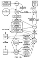
- FIG. 3a-5 the general methodology of measuring cardiac output in a living subject is described.
- the thoracic impedance Z T ( t ) of a living subject may be modeled as comprising a constant impedance, Z o , and time-varying impedance, ⁇ Z(t) .
- this change in thoracic impedance, ⁇ Z (t) is related to the pulsatile blood volume change.
- effectively constant tissue impedances such as bone, muscle, and fat are modeled as a conducting volume Z o 102 in parallel with the pulsatile impedance of the blood ⁇ Z (t) 104.
- This second impedance 104 is a time-varying fluid column with resistivity, p, cylindrical length, L , and a time-varying cross-sectional area that oscillates between zero and a value A, the latter which correlates to the stroke volume V.
- Z o the conducting tissues and fluids
- the ventricular ejection time is estimated from features in the impedance waveform, which is obtained from the measurement terminals of the electrode arrays 302, 304, 306, 308 placed on various locations of the subject's thorax as illustrated in Figs. 3a and 3b .
- a value of 150 ohm-cm is used for the resistivity of the blood, although it will be recognized that other values may be substituted as appropriate.
- the typical impedance associated with a human subject's skin is 2 to 10 times the value of the underlying thoracic impedance Z T ( t ).
- the present invention may use at least two, and typically four electrode arrays 302, 304, 306, 308 for measurement, as shown in Fig. 3a . The physical construction and these electrode arrays is described in detail with reference to Figs. 7a-8 herein.
- one electrode array 302 comprising a stimulation electrode terminal 310 and a measurement electrode terminal 312 is applied above the thorax 300 of the subject, while a second electrode array 304 (having stimulation electrode terminal 314 and measurement electrode terminal 316) is applied below the thorax 300.
- the AC current from the current source is supplied to the stimulation electrode terminals 310, 314.
- current flows from each stimulation electrode terminal 310, 314 through each constant skin impedance, Z sk1 or Z sk4 , each constant body tissue impedance, Z b1 or Z b1 , and each constant skin impedance, Z sk2 or Z sk3 , to each measurement electrode terminal 312, 316.
- the voltages at the measurement electrode terminals 312, 316 are measured and input to a differential amplifier to obtain the differential voltage, V T (t).
- the desired thoracic impedance, Z T (t) is then obtained using the relationship of Eqn. (4).
- two sets of electrode arrays may advantageously be used to monitor the impedance associated with the left and right portion of the thorax 300 in the present invention.
- the four measurement arrays are also used to obtain an electrocardiogram (ECG), based on one of four vectors modified from Lead I, II, III, or IV.
- ECG electrocardiogram
- the resulting electrocardiograms are based on the original Lead configurations, but are not of diagnostic quality.
- the Q wave of the ECG QRS interval is used to determine the heart rate and to trigger measurements of VET within the dZ t dt waveform.
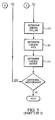
- Fig. 5 illustrates the logical flow of the method of measuring cardiac output which may be performed by apparatus according to the invention.
- the method 500 generally comprises first providing a plurality of electrode "arrays" of the type previously described herein per step 502.
- the electrode arrays are positioned at predetermined locations above and below the thoracic cavity per step 504, as illustrated in Fig. 3a herein. In one embodiment of the method, these locations are chosen to be on the right and left sides of the abdomen of the subject, and the right and left sides of the neck. These locations, with prior art band electrodes, were first used by Kubicek. Other locations and/or combinations of arrays may be substituted with equal success.
- a substantially constant AC current is generated in step 506, and the current applied to the stimulation electrode terminal 310, 314 of each of the electrode arrays in step 508.
- the voltage generated at the measurement electrode terminal 312, 316 of each electrode array is next measured in step 510. As previously discussed, this voltage is generally reduced from that applied to the stimulation electrode by virtue of the impedance of, inter alia, the thoracic cavity. Note that the measured voltage may be absolute, or relative (i.e., a differential voltage) as desired.
- step 512 the cardiac stroke volume from the measured voltage, using for example the relationship of Eqn. (3) above. Cardiac rate (step 514) is also determined by using the measurement electrodes to sense the ECG potentials generated by the heart of the subject.
- cardiac output is determined based on the stroke volume determined in step 512 and the cardiac rate in step 514 using the relationship of Eqn. 1 above.
- the system 600 generally comprises an alternating current (AC) current source 604 capable of generating a substantially constant current, a plurality of electrical leads in the form of a multi-ended lead assembly 606 for connecting the instrument monitor 607 to the individual terminals of the electrode arrays 302, 304, 306, 308, a processor 608 with associated algorithms capable of running thereon for performing analysis of the signals measured from the measurement terminals, data and program memory 609, 610 in data communication with the processor 608 for storing and retrieving program instructions and data; an I/O interface 611 (including analog-to-digital converter) for interfacing data between the measurement electrodes and the processor 608; a mass storage device 612 in data communication with the processor for storing and retrieving data; a display device 614 (with associated display driver, not shown) for providing an output display to the system operator,
- AC alternating current
- processor 608, memory 609, 610, I/O interface 611, mass storage device 612, display device 614, and input device 616 may be embodied in any variety of forms, such as a personal computer (PC), hand-held computer, or other computing device.
- PC personal computer
- I/O interface 611 I/O interface 611
- mass storage device 612 mass storage device 612
- display device 614 input device 616
- input device 616 may be embodied in any variety of forms, such as a personal computer (PC), hand-held computer, or other computing device.
- the applied current derived from the current source 604 is a 70 kHz sine wave of approximately 2.5 mA peak-to-peak.
- the measured voltage associated with the aforementioned sine wave is on the order of 75 mV peak-to-peak.
- the electrode lead assembly 606 of the illustrated embodiment contains a ten wire assembly (two wires are left unused) that branches to eight individual connectors 606a-h.
- the conductors 613a-j of the lead assembly are fashioned from electrically conductive material such as copper or aluminum, and are insulated using a polymer-based insulation having the desired dielectric strength as is well known in the electrical arts.
- the length of the conductors may also be controlled so as to match the impedance of each individual conductor to that of the others within the assembly 606.
- the body surface potential is measured between two measurement electrodes.
- This time-varying voltage reflects the electrical activity of the heart, and contains one QRS interval per cardiac cycle.
- the biopotential is analyzed to identify each QRS complex.
- the frequency of QRS complexes determines the heart rate.
- the Q wave within the QRS complex is then used to trigger identification of VET within the dZ t dt waveform, as the opening of the aortic valve (the beginning of VET) occurs after the appearance of the Q wave.
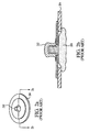
- each array comprises a flexible substrate 704 having a plurality of apertures 706, 708 formed therein.
- two terminals 310, 312 are disposed through the apertures such that the top portions 716, 718 of the terminals project above the plane of the substrate 704.
- the two terminals 310, 312 comprise a stimulation terminal 310 and measurement terminal 312 as previously described with respect to Fig. 3a .
- the stimulation terminal 310 is used to apply the potential necessary to generate the current flowing through the thoracic cavity of the subject.
- the asymmetric shape of the substrate 704 of the embodiment of Figs. 7a-7c may be used to assist the clinician in rapidly determining which electrode is the stimulation electrode and which the measurement electrode, such as by assigning a convention that the end of the array having a given shape always contains the stimulation electrode.
- the substrate may be shaped to adapt to certain physical features of the patient, such as by using a substrate having a broader width so as to better conform to the generally cylindrical shape of the subject's neck. Any number of different substrate shapes may be employed; Fig. 7d illustrates one such alternative shape.
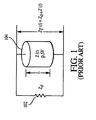
- the terminals 310, 312 are firmly held in place within the substrate 704 at a predetermined distance 705 by a mounting element 707 or any one of a variety of other constructions as will be described in greater detail below.
- the distance (measured centerline-to-centerline on the terminals 310, 312) is approximately 5 cm in the embodiment of Fig. 7a , although it will be recognized that other distances may be substituted. Desired distances may be determined through experimentation, anecdotal observations, calculations, or any other suitable method; however, experimental evidence obtained by the Applicant herein indicates that a distance of 5 cm is optimal for impedance cardiography measurements.
- the substrate 704 in the embodiment of Fig. 7a is formed from a Polyethylene foam, although other materials such as cloth or vinyl may be substituted.
- the polyethylene foam is chosen for its compliance and flexibility, thereby allowing it to conform somewhat to the contours of the subject's anatomy, while still maintaining sufficient rigidity for maintaining the terminals 312, 314 in the desired position and orientation.
- the terminals 310, 312 of each array comprise a generally cylindrical shaped sidewall portion 720 having a first diameter 722, and a top portion 724 having a second diameter 726, the second diameter 726 being greater than the first diameter 722 in order to assist in retaining a connector mated to the terminal 310, 312 as described in greater detail below.
- the outer wall 721 of the sidewall portion 720 is essentially vertical in orientation (i.e., parallel to the central axis 725 of the terminal 310, 312), while the top portion is progressively rounded as shown.
- the terminals may be manufactured from an extruded metal such nickel, with a coating of brass, or may be molded from carbon.
- the terminals may be molded of plastic, and coated with a metal such as gold or impregnated with carbon.
- a metal such as gold or impregnated with carbon.
- the extruded metal possesses the advantage of low cost, while the molded plastic impregnated with carbon possesses the advantage of radiolucency.
- a terminal molded of plastic and coated with gold may possess low noise artifact.
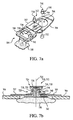
- the terminals 310, 312 of the electrode array comprise a two piece construction, having an upper terminal element 730 and a lower terminal element 732 as shown in Figs. 7a and 7b .
- the post 734 of the lower terminal element 732 is adapted to be frictionally received within the cavity 736 of the upper terminal element when the two components are mated.
- the upper and lower elements 730, 732 form a single unit when assembled, with the mounting element 707 being frictionally held or "pinched" between the lower surface 740 of the upper element 730 and the upper surface 742 of the lower element 732.
- the post 734 of the lower element perforates the mounting element 707, or alternatively penetrates through a pre-existing aperture 738 formed therein.
- the lower elements 730, 732 of the electrode array terminals 310, 312 are coated with Ag/AgCl, although other materials with the desirable mechanical and electrochemical properties such as Zinc Chloride may be used if desired.
- the electrolytic element 750 of each electrode array comprises an electrolytic gel of the type well known in the bio-electrical arts; in the present embodiment, the gel comprises an ultraviolet (UV) cured potassium chloride (KCl) gel, although it will be recognized that other types of compounds or materials may be used. UV curing of the gel allows the element 750 to have a more solidified consistency and improved mechanical properties, thereby preventing excessive spreading or thinning of the element when the array is applied to the subject while still maintaining its overall adhesiveness and electrolytic properties. As shown in Figs. 7b and 7c , the element 750 is sized so as to encompass the edges 752 of the respective aperture 706, 708 in the substrate 704 over which it is placed when assembled, although other configurations may be used.
- UV ultraviolet
- KCl potassium chloride
- the top portion 755 of the element 750 fits at least partially within the aperture 706, 708 and conforms substantially thereto, thereby effecting contact with the bottom surface 760 of the bottom terminal element 732. In this way, ions are passed between the skin of the subject and the terminals of the array via the gel element 750.
- the gel also provides for adhesion of the array to the skin of the subject, although the array of the present embodiment also includes a separate adhesive 762 which is applied to the bottom surface of the substrate 704, as shown in Fig. 7c .
- the gel of the element 750 is advantageously placed in the embodiment of Figs. 7a-c so as to be symmetric with respect to the terminal 310, 312. It will be recognized, however, that the element(s) 750 may also be placed so as to produce certain desired electrolytic conditions. Similarly, the element 750 may be split into two or more component parts if desired.
- Figs. 7a-c employs two fixed terminals that are effectively immovable within the substrate
- means for allowing adjustment or change of the relative position of the terminals may be substituted.
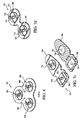
- a terminal array having three terminal posts may be used, the second post 802 being spaced a first distance 804 from the first post 806, and the third post 810 being spaced a second distance 808 from the first post 806, such that the clinician can select one of two terminal spacings as desired.
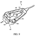
- each electrode lead assembly connector 606a-h is designed to mitigate the downward force required to mate the connector with its respective electrode array terminal.
- each connector 606a-h contains two spring-biased conductive jaws 902 that are spread apart by the cam surface 904 of an actuator button 906 disposed on the front 907 of the connector body 908.
- the connector jaws 902 and bias mechanism are designed to allow the upper and sidewall portions 724, 720 of the electrode terminal 310, 312 ( Fig. 7b ) to be received within the recess 910 of the jaws 902 when the button 906 is fully depressed. In this fashion, effectively no downward force is required to engage the connector to its respective terminal.
- the jaws 902 are contoured to engage substantially the entire surface of the sidewall portion 720 of the terminal when the actuator button 906 is released. Since the sidewall portion 720 of the terminal is effectively circular in cross-section, the connector may advantageously rotate around the axis of the terminal 310, 312 when lateral tension is applied to the conductor attached to that connector.
- U.S. Patent No. 5,895,298 issued April 20, 1999 entitled “DC Biopotential Electrode Connector and Connector Condition Sensor,” and incorporated herein by reference in its entirety, describes a bias jaw electrical connector of the type referenced above in greater detail.
- each connector 606a-h is fastened to one of the two terminals 310, 312 of an electrode array.
- the 68 kHz constant current is applied from the current source to four electrode terminals (i.e., one terminal per array).
- complete circuits are formed between the current source and the I/O device 611 of the system 600 via the electrical conductors and connectors associated with the stimulation electrode terminals, the stimulation electrode terminals themselves, the thorax of the subject, the measurement terminals, and the electrical conductors and connectors associated with the measurement terminals.
- Fig. 10 the method of evaluating the electrical continuity of one or more leads within the system is described. Note that while the following description is based on the two-terminal array configuration ( Figs 7a-7c ) and the use of four arrays as shown in Fig. 3a , the method may be applied to many alternate configurations with equal success.
- the electrode arrays are disposed on the skin of the subject.
- the position at which the electrode arrays are disposed on the subject are measured in relation to the thoracic cavity as illustrated in Fig. 3a , or alternatively may be inferred by the weight and height of the subject.
- a current is generated between the stimulation electrodes and the measurement electrodes of the respective arrays in step 1004. As previously discussed, the current passes through at least a portion of the subject's thoracic cavity, encountering a time-variant impedance therein.
- An impedance waveform is then measured from two or more of the measurement terminals of the arrays in step 1006.
- the waveforms comprise measurements of impedance as a function of time, which is well known in the cardiographic arts. These measured waveforms are then compared to one another in step 1008 to detect changes or variations between them.
- two waveforms are differenced by way of a simple differencing algorithm resident on the processor 608 of the system 600 ( Fig. 6 ), although it will be recognized that other approaches may be used.
- the base impedance may be calculated for the left and right sides. The larger base impedance may then be subtracted from the smaller base impedance, with this difference then divided by the smaller impedance.
- the resulting percentage ratio when greater than a predetermined threshold value, may represent the presence of detached or loose electrodes. While some variation between the waveforms is normal, significant variations are indicative of either a degraded electrical connection, such as between the electrode array terminal and its respective connector, or between the electrolytic gel and the skin of the patient, or even the gel and the terminal of the array or between the cable and connector.
- a threshold value is determined and set by the operator of the system in step 1010 such that when the threshold "difference" is exceeded as determined by the aforementioned algorithm (step 1012), the operator will be alerted to the degraded condition such as by a visual or audible alarm in step 1014.
- the difference in impedance (or voltage) between the individual terminals 310, 312 of one or more electrode arrays is measured and used as the basis for the continuity determination. Specifically, the difference in the values measured from one terminal 310 with respect to another terminal 312 of the exemplary two-terminal array 302 illustrated herein is measured; when this value exceeds a certain threshold difference value (e.g., 650 Ohms, although other values may be substituted based on any number of factors), a loose electrode or otherwise degraded connection is suspected. It will be recognized that this methodology may also be employed when more that two electrical terminals are electrically connected to the system.
- a certain threshold difference value e.g., 650 Ohms, although other values may be substituted based on any number of factors
- the algorithm would be adapted to measure the difference between each of the non-repeating permutations (i.e., 1-2, 1-3, and 2-3) and compare such differences to the threshold.
- the aforementioned threshold value may be algorithmically determined and/or parametrically variant. For example, based on data obtained by the system before and/or during operation, the apparatus of the present invention may periodically or continuously calculate new threshold values as a function of time. Alternatively, the system may be adapted to calculate a plurality of such impedance difference values across each of the terminal arrays in use, and average the values periodically to maintain a "moving average" of impedance differences. As yet another alternative, other physiological parameters of the subject being monitored could be used as "triggers" for revised threshold determination and/or impedance difference calculation.
- the use of the multi- terminal electrode arrays having predetermined and substantially equal terminal spacing as previously described allows such comparisons between electrode waveforms to be made; errors resulting from uncontrolled spacing of the terminals are effectively eliminated.
- the aforementioned method would be largely ineffective, since these error sources would force the threshold value to be set artificially high, thereby potentially masking conditions of degraded electrical continuity which could affect the ultimate accuracy of and cardiac output estimation made by the system.
- the ICG module utilizes the electrical bioimpedance measurements previously described herein to continuously generate a signal indicative of pulsatile thoracic impedance changes.
- This pulsatile thoracic impedance signal is processed to produce signals indicative of other related parameters, such as the ventricular ejection time (VET) and the maximum rate of change of pulsatile thoracic impedance, which are used to calculate the volume of blood pumped per stroke according to equations previously discussed.
- VET ventricular ejection time
- VET maximum rate of change of pulsatile thoracic impedance
- the voltage developed across the thoracic impedance at any instant in time can vary due to a number of different factors. Specifically, the voltage is affected by four primary components: (i) base impedance; (ii) respiration; (iii) cardiac changes; and (iv) patient motion.
- the base impedance comprises the largest component of the modulated waveform, and represents the nominal conductivity of the thorax. It is a function of the tissue and fluid distribution within the interrogated area.
- the average value of the base impedance, or TFI is roughly 30 Ohms, but can vary from 5 to 60 Ohms in adult humans.
- the ventilation cycle is relatively long, typically 0.2 to 0.7 Hz with variable magnitude.
- Impedance changes occur due to the cardiac cycle, such as after ventricular depolarization (QRS complex), and have very small magnitudes (approximately 0.05 - 0.3 Ohms). These impedance changes are the result of aortic expansion after blood is ejected from the ventricle, and contraction as blood is flows into the circulatory system.
- QRS complex ventricular depolarization
- Movement by the patient causes significant impedance changes due to fluid shifts and density/volume changes in the thorax, with varying frequency and magnitude.
- the motion component of impedance is effectively eliminated when the patient is monitored at rest.
- Fig. 11 is a graph illustrating the frequency ranges of these four signal components for a typical adult human subject.
- the ICG module advantageously addresses the foregoing components of thoracic impedance through its signal processing circuitry and algorithms, now described in detail.
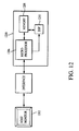
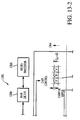
- the ICG module 1200 is electrically coupled to the host monitor 1202 via the interface device 1204.
- the ICG module 1200 generally comprises a microprocessor 1206, storage device 1208, and digital signal processor 1210, as described in greater detail below with respect to Fig. 13 .
- the module 1200 communicates with a host monitor 1202 to continuously monitor and display the cardiac output and pulse rate of the subject under evaluation. Communications are in the illustrated embodiment conducted according to a predetermined protocol (such as a serial interface protocol of the type well known in the art), although other approaches may be substituted with equal success.
- the module further includes other features such as input power conditioning and "soft-start" current limiting functionality, software/firmware download from the host device, and electrical isolation (e.g., 4000 V) for the subject being monitored.
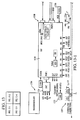
- the exemplary embodiment of the module 1200 comprises two component boards 1302, 1304, identified herein as the "patient board” 1302 and the “processor board” 1304. It will be recognized that these may or may not be separate physical boards or substrates.
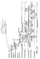
- the patient board 1302 provides a number of functions, including (i) interface with the external signal sources; e.g., the patient leads and electrodes which provide, inter alia, the impedance and ECG waveform signals to the module; (ii) ECG vector select (described in greater detail below); and (iii) input signal filtration, conditioning, and domain conversion.
- the patient board 1302 also isolates the electrical (ECG) the mechanical ( ⁇ Z) components of cardiac activity from each other, and from the components of respiration and motion present in the signals derived from the subject under evaluation.
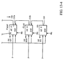
- a first high-pass filter (pole at 0.33 Hz) 1306 filters the input impedance waveform 1307 and ECG waveform 1308.
- Band-pass filters 1309a, 1309b comprising a low-pass filter with pole at 1.59 MHz and high-pass filter with pole at 9.72 kHz are used to further filter the respective high-pass filtered impedance waveforms of each input channel (a channel being defined for the purposes of this exemplary discussion as a pair of electrodes; i.e., "left" channel and "right” channel).
- Fixed gain amplifiers 1310a, 1310b receive the output of the band-pass filters 1309a, 1309b for each channel, and provide a fixed gain output signal to respective digital potentiometers 1311a, 1311b, the output of which is supplied to respective demodulators/filters 1312a, 1312b.
- the output of the demodulator/filter units 1312a, 1312b is passed through 5 M Ohm resistors and subsequently input to respective analog-to-digital converters (ADCs) 1313a, 1313b, which are clocked according to a 2 MHz clock signal (described below).
- ADCs analog-to-digital converters
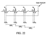
- the patient board 1302 further comprises a plurality of ECG inputs 1314 which are obtained from the aforementioned electrode pairs and input to a crosspoint switch 1315 (e.g., a 16 x 16 analog multiplexer such as the AD75019 device manufactured by Analog Devices), which selects the best "quality” input from among the four inputs as described in detail below with respect to Figs. 20-22 .
- the selected ECG signal is low-pass filtered 1316, amplified to a fixed gain 1317, high-pass filtered 1318, and then supplied (via 1 M Ohm resistor) to the ECG ADC 1319.
- the three ADCs 1313a, 1313b, 1319 output digitized signals to the DSP 1210 on the processor board 1304, described below.
- the patient board 1302 also uses this crosspoint switch to provide several other functions, including connection of leads to the patient, provision of multiple ECG vectors, loose electrode testing (previously described), cable identification, and calibration.
- the processor board 1304 comprises a digital signal processor (DSP) 1210 with direct memory access (DMA) of the type well known in the electronic arts, a microprocessor 1206, a storage device 1208 coupled with the DSP 1210 and microprocessor 1206 via a data bus, a first signal (constant current) source 1330 generating a nominal 70 kHz output signal, a second signal source 1332 generating a nominal 2 MHz output signal, a clock signal generator (12 MHz nominal), and digital-to-analog converter (DAC) 1334.
- DSP digital signal processor
- DMA direct memory access
- the module is configured with a DC/DC converter operating at 90 kHz, and the aforementioned ICG current source at 70 +/- 6 kHz.
- Fig. 13a graphically illustrates the impedance signal extraction process performed by the ICG module 1200.
- the microprocessor 1206 comprises a microcomputer running at a crystal frequency of approximately 32.7 KHz, although it will be recognized that other platforms may be substituted with equal success.
- the system clock is generated by an on-chip phase-locked loop (PLL) and is software programmed for an operating frequency of 16 MHz.
- PLL phase-locked loop
- the device is operated in the 8-bit bus operating mode with all data transfers occurring on data lines 8 through 15.
- the processor also has a QSPI built in, which in the present embodiment is used for communications to the host device, such as by using a serial interface protocol of the type previously referenced herein.
- the ICG module 1200 utilizes a three-part software architecture comprising three modules: (i) "Initialization” module; (ii) “Operating” module; and (iii) "Processing” module. Any one of the three software code modules can be independently downloaded.
- the Initialization operating system of the microprocessor 1206 comprises a variant of the "C Executive" system manufactured by JMI Software Consultants, Inc., although it will be recognized that other operating systems may be substituted.
- C Executive comprises a real-time, memory-resident, event driven monitor program designed for embedded systems which require multi-tasking functionality and ROM storage.
- the initialization module software uses the initialization OS for process scheduling, input and output, and inter-process communication.
- Fig. 13b graphically illustrates the high-level program flow of the Operating software module of the illustrated embodiment.
- the processing module executes the bioimpedance algorithms. It also controls peripheral functions, such as the gain of the impedance amplifiers, the setting the ECG vector, reading of the impedance and ECG A/D converters, and detection of electrical continuity.
- the DSP 1210 adapted for use with the invention comprises an Analog Devices ADSP-2181 device, although it will be recognized that any digital processing device adapted for algorithms such as those described herein may be used with proper adaptation. For example, members of the Texas Instruments 'C4x family of floating point DSPs, 'C5x family of fixed point processors, 'C6x family of VLIW processors, the Lucent DSP 16000 family, or even a user-customized processor core or ASIC may be used. Many other types of digital signal processors exist, any number of which may be adapted for use with the present invention.
- Parameters determined from the digitized data are communicated to the microprocessor 1206 via the storage device 1208, specifically by writing data words to predetermined locations within the storage device.
- a dual-port RAM (DPR) is selected to allow dual-port access and two-way communication by the DSP 1210 (via, e.g., the BDM port) and microprocessor 1206 via first and second memory ports, respectively; however, it will be recognized that other types and configurations of storage device including DRAM, SDRAM, SRAM, dual data rate synchronous DRAM (DDR-SDRAM), ROM, or even non-semiconductor storage devices may be substituted.
- DRAM dual-port RAM
- SRAM dual data rate synchronous DRAM
- ROM dual data rate synchronous DRAM
- non-semiconductor storage devices may be substituted.
- Fig. 13 further comprises a DMA unit of the type well known in the art, thereby facilitating direct memory accesses by the processor(s).
- the module 1200 is further configured such that address and data bus interfaces exist between the microprocessor 1206 and storage device 1208, and between the DSP 1210 and storage device 1208, thereby providing for memory addressing and data transfer by both processors.
- Fig. 13c illustrates one exemplary embodiment of the memory map used with the DPR 1208 of the ICG module.
- An address range is also specified at the microprocessor 1206 and connected to the DSP's DMA port 1350 for DSP code download from the microprocessor 1206 (and host 1202) to the DSP 1210 during operation.
- the impedance and ECG waveform data present within the module consists of all measured and calculated parameters related to a specific cardiac event, without any averaging.
- the start of data is placed at the Q point of the cardiac cycle measured.
- Table 2 illustrates the data write operations into memory performed by the DSP 1210 at a 200Hz rate: Table 2 Data Memory address Description ⁇ Z 7FA0 ECG 7FA2 Respiration 7FA4 dZ/dt 7FA6 pacer impulse 7FA8 Pace enhanced ECG 7FAA ECG + pacer spikes ECG gain factor 7FAC Loose Electrode 7FAE
- the module 1200 further utilizes a 512K x 8 static RAM (SRAM) array for temporary data storage.
- SRAM static RAM
- the static RAM is also used as temporary storage of ICG Monitor program code during program download of the software.
- the program code is stored in a 128K x 8 sectored "flash" EPROM. This device can be erased on an individual sector basis.
- the first sector of the flash memory is used for storing the initialization (boot-up) code. In general, this sector of code is not modified, thereby ensuring that even if a download of code fails, the module will still be able to attempt another download.
- the other seven sectors of the flash memory are used for storage of the Operating code.
- the Operating code is the code which is run during normal operation of the module. This code can be updated using the host monitor or other external storage device.
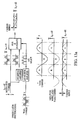
- the SPORT0 is a standard port of the DSP which is used to transmit setup control to the ADCs 1313a, 1313b, 1319, digital potentiometers 1311a, 1311b, and the crosspoint switch, and receive data from the ADCs.
- DSP port SPORT1 is used to transmit data to the DAC 1334.
- Fig. 13d graphically illustrates the SPORT0 and ADC data acquisition and timing relationships of the present embodiment in detail.
- Fig. 14 illustrates portions of the data and signal flow within and between the patient and processor boards (and associated components) of the ICG module of Figs. 12-13 .
- Appendix I hereto provides a listing of the various parameters utilized within or generated by the ICG module 1200.
- VEPT Volume of Electrically Participating Tissue
- BSA Body Surface Area
- Hemodynamic parameters are calculated from the values HR, PEP, VET, TFI, dZ t dt max and d 2 ⁇ Z t dt 2 max which are extracted from the aforementioned ECG, dZ t dt and d 2 ⁇ Z t dt 2 waveforms.
- Indexed parameters are obtained by dividing the parameter (e.g., BSA, CO, CI, SI) by the appropriate index.
- Appendix II details the communications protocol (including memory address) for the patient data communicated by the exemplary embodiment of the module to the host device.
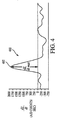
- Two important parameters present in estimations of cardiac output are (i) the maximum negative change in the impedance signal ( Z ( t )) as a function of time, dZ t dt max ; and (ii) the ventricular ejection time (VET).
- These parameters, as well as other related parameters, are found from features referred to as "fiducial points" that are present in the inverted first derivative of the impedance waveform, dZ t dt .
- the maximum value of dZ t dt referred to as dZ t dt max
- C point the time at which the inverted derivative value has the highest amplitude
- VET also known as LVET, relating to the left ventricle of the heart in a human
- That point in time associated with aortic valve opening also commonly known as the "B point”
- B point is generally determined as the time associated with the onset of the rapid upstroke (a slight inflection) in dZ t dt before the occurrence of the C point.
- the time associated with aortic valve closing also known as the "X point” is generally determined as the time associated with the inverted derivative global minimum, which occurs after the C point.
- the O point represents the time of opening of the mitral valve of the heart.
- the O point is generally determined as the time associated with the first peak after the X point.
- the time difference between aortic valve closing and mitral valve opening is known as the iso-volumetric relaxation time, IVRT.
- Impedance cardiography further requires recording of the subject's electrocardiogram (ECG) in conjunction with the thoracic impedance waveform previously described.
- ECG electrocardiogram
- Processing of the impedance waveform for hemodynamic analysis requires the use of ECG fiducial points as landmarks.
- Processing of the impedance waveform is generally performed on a beat-by-beat basis, with the ECG being used for beat detection.
- detection of some fiducial points of the impedance signal may require the use of ECG fiducial points as landmarks.
- individual beats are identified by detecting the presence of QRS complexes within the ECG.
- the peak of the R wave (commonly referred to as the "R point") in the QRS complex is also detected, as well as the onset of depolarization of the QRS complex ("Q point").
- R point The peak of the R wave
- Q point the onset of depolarization of the QRS complex
- the ICG module for use in the present invention is further modified to incorporate fiducial point detection within the aforementioned impedance and/or ECG waveforms provided as inputs to the module.
- “event markers” are placed within the waveform buffers to indicate the algorithm detection points with reference to the waveform samples.
- Table 4 shows some of the marker values used for the various fiducial points: Table 4 Fiducial Point Marker Value Q point 0x10 B point 0x20 X point 0x30 dZ/dt max 0x50 d 2 Z/dt 2 max 0x60
- LVET ventricular ejection time
- fiducial point detection within the ICG module is conducted using the wavelet transform methodology as disclosed in co-pending U.S. patent application publication number US 20020138014 .
- the fiducial points of the ⁇ Z and dZ/dt waveforms (e.g., B, C, X, and O) are detected in this variant using discrete wavelet transforms, rather than by empirical detection, which is based on processing features in the first and second derivatives of ⁇ Z(t).
- the wavelet transform methodology advantageously requires only simple additions and multiplications of real numbers, thereby substantially simplifying the processing associated with the cardiac output (CO) determination performed by the DSP 1210 and associated algorithms.
- the wavelet transform methodology compared to the empirical methodology, is much less sensitive to noise artifact.
- fiducial points are utilized in evaluating the electrocardiogram (ECG) waveform of the subject, with specific individual "beats" of the subject's cardiac muscle being identified through detection of one or more fiducial points, either by the aforementioned wavelet transforms or by other means.
- ECG electrocardiogram
- the peak of the R wave (R point) in the QRS complex as well as the onset of depolarization of the QRS complex (Q point) are also detected.
- the time interval between the R waves is also used to calculate the subject's heart rate.
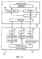
- Figs. 15a-c one embodiment of the ICG module for use in the present invention adapted for rack mounting is described.
- the module 1500 is fitted with a faceplate 1502 disposed generally at the front portion 1506 of the module housing 1504, as well as a plurality of electrical connectors 1510, 1512, one connector 1510 disposed generally at the front portion 1506 of the housing, and one connector 1512 at the rear portion 1515 of the housing 1504.
- a debug port connector (not shown) is also provided to facilitate debug of the microprocessor 1206.
- Optional module status indicators 1520 are also disposed on the faceplate 1502 so as to be viewable by a user or clinician during operation of the module when the module is received within an equipment "rack" (described in greater detail below).
- the module housing 1504 is shaped and sized so as to be received within the rack adjacent or generally in proximity to other modules, such that space is economized.
- the front panel connector 1510 comprises the ICG module interface with the patient being monitored, including electrical connection to the measurement and stimulation electrode terminals previously described herein.
- the front panel connector 1510 may be of any configuration, such as a multi-pin standardized male or female electrical connector of the type well known in the art, although literally any configuration (proprietary or otherwise) may be substituted.
- the rear panel connector 1512 allows for electrical connection of the module to the host monitor/interface unit, such as for example via a multi-pin female connector for mating with backplane connectors of the host monitoring equipment (including any voltage supply associated therewith). It will be recognized, however, that other types and "pin-outs" of connector or data/power interface may be substituted with equal success, dependent primarily on the host equipment with which the module must interface.
- the equipment module 1500 of Fig. 15 may also be configured with a network data interface (described in detail below with respect to Fig. 19 ), thereby allowing the distribution of data to a plurality of different local and/or remote nodes for analysis, storage, or other functions.
- a network data interface described in detail below with respect to Fig. 19
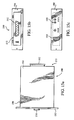
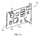
- Fig. 16 illustrates yet another embodiment of the ICG module for use in the invention, configured as a plug-in circuit card 1600 for use within a host device such as a dedicated stand-alone monitor or host monitoring device (e.g., one that has a primary function which may or may not be related to ICG or cardiography), personal computer, laptop computer, hand-held computer, minicomputer, or SUN UNIX workstation.
- the circuit card 1600 integrates all of the functionality of the embodiment of Fig. 1300, including processor and patient interface boards, onto one card substrate 1602.
- a standardized edge-type electrical connector 1604 is also provided to permit interface with the card receptacle of the host device (not shown), which may be configured according to any electrical interface standard (such PCMCIA, PC Card, or otherwise).
- the ICG module for use in the invention comprises a card generally similar to that shown in Fig. 16 , except that the edge-type connector 1604 is replaced with a ribbon-cable and associated connector (or other type of connector) of the type well known in the electrical arts for interfacing the module with other circuit elements and boards within the host device.
- the ICG module may be plugged directly into another module within the host device. It will be recognized that literally any type of electrical interconnection scheme and protocol between the ICG module (whether in "card” form as in Fig. 16 or otherwise) and the host device with which the module is used may be employed consistent with the invention.
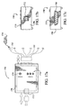
- Figs. 17a-c illustrate yet another embodiment of the ICG module, configured as a "yoke" 1700 adapted for mobility and electrical interface with a monitoring device.
- the term yoke is meant to include any configuration of mobile or transportable device which is used to facilitate centralization of a plurality of patient signals.
- the yoke 1700 is adapted to receive a plurality of electrical leads 1702 (whether as individual leads, in one variant, or as a single multi-terminal electrical connector 1708, in another variant) which are connected to the electrodes 1704 disposed on the thorax of the patient being monitored.
- the yoke 1700 is configured to be light weight and rugged, and utilizes a molded plastic impact-resistant housing 1706 of the type well known in the polymer arts, although other materials may be used.
- the yoke housing 1706 contains the electronics of the ICG module, including processor and patient interface boards (not shown), and further optionally includes an LED 1710 or other status indication for the ICG module.
- the output of the ICG module electronics in the yoke 1700 is transferred to the monitoring device (not shown) via a data interface 1712, in the present embodiment a universal serial bus (USB) connection and cable of the type well known in the electrical arts.
- USB universal serial bus
- a wireless interface between the yoke 1700 and host monitor may be used.
- an RF transceiver and modulator device are provided and adapted to generally comply with the well known "BluetoothTM" wireless interface standard.
- the Bluetooth "3G” wireless technology allows users to make wireless and instant connections between various communication devices, such as mobile devices (e.g., cellular telephones, PDAs, notebook computers, local or remote patient monitoring stations, and the like) and desktop computers or other fixed devices.
- the Bluetooth topology supports both point-to-point and point-to-multipoint connections. Multiple "slave" devices can be set to communicate with a 'master' device.
- the yoke 1700 when outfitted with a Bluetooth wireless suite, may communicate directly with other Bluetooth compliant mobile or fixed devices including a receiver disposed at the host monitor, or alternatively other Bluetooth-capable devices such as a cellular telephone, PDA, notebook computer, or desktop computer. Alternatively, WMTS telemetry may be utilized.
- the operation of the wireless interface is effectively transparent to the yoke 1700 and host monitor, although it will be recognized that data may be "buffered" within one or more intermediary storage devices (not shown) if desired.
- the signal processing and transceiver/modulator components of the interface may be embodied in a fully integrated "system on a chip” (SoC) application specific integrated circuit (ASIC) of the type generally known in the semiconductor fabrication arts (not shown).
- SoC ASIC incorporates, inter alia, a digital signal processor (DSP) core, embedded program and data random access memories, RF transceiver circuitry, modulator, analog-to-digital converter (ADC), and analog interface circuitry necessary to support sampling, conversion, processing, and transmission of the cardiac output (or other) data to the host monitor's receiver.
- DSP digital signal processor
- ADC analog-to-digital converter
- a number of different subjects undergoing cardiac monitoring/analysis using the yoke 1700 may be monitored in real time at a centralized location using a single monitor receiver.
- the monitor receiver (not shown) and transceiver are adapted to receive a plurality (currently seven, under prevailing Bluetooth architecture, although such number may be increased or decreased) of signals from remote ICG module devices, whereby the individual signals may be multiplexed or alternatively processed in parallel by the host monitor and interface (with the addition of appropriate multiplexing or parallel processing hardware of the type well known in the electronic arts).
- a host monitor configured to receive such multiplexed or parallel channel data may be used to monitor the cardiac output and other related parameters of multiple subjects at once.
- Bluetooth-compliant devices operate in the 2.4 GHz ISM band.
- the ISM band is dedicated to unlicensed users, including medical facilities, thereby advantageously allowing for unrestricted spectral access.
- Maximum radiated power levels from the yoke's transceiver are in the mW range, thereby having no deleterious effect on the physiology of the subject due to radiated electromagnetic energy.
- radiated power from the antenna assembly (not shown) of the yoke transceiver may also be controlled and adjusted based on relative proximity of the transceiver, thereby further reducing electromagnetic whole body dose to the subject.
- the modulator of the yoke uses one or more variants of frequency shift keying, such as Gaussian Frequency Shift Keying (GFSK) or Gaussian Minimum Shift keying (GMSK) of the type well known in the art to modulate data onto the carrier(s), although other types of modulation (such as phase modulation or amplitude modulation) may be used.
- GFSK Gaussian Frequency Shift Keying
- GMSK Gaussian Minimum Shift keying
- Spectral access of the device may be accomplished via frequency divided multiple access (FDMA), frequency hopping spread spectrum (FHSS), direct sequence spread spectrum (DSSS, including code division multiple access) using a pseudo-noise spreading code, or even time division multiple access, depending on the needs of the user.
- FDMA frequency divided multiple access
- FHSS frequency hopping spread spectrum
- DSSS direct sequence spread spectrum
- any wireless interface capable of accommodating the bandwidth requirements of the system may be used, such as the new WMTS biomedical band of 608 - 614 MHz.
- an infrared device e.g., Infrared Data Association "IrDA”
- IrDA Infrared Data Association
- Fig. 18 is a perspective view of the yoke of Figs. 17a-c , adapted for wireless communication with the monitoring device as just described.
- a network interface device 1902 e.g., LAN card
- the network interface card 1902 and connector 1904 allow the cardiac output (CO) and other data generated by the module to be transferred to one or more remote nodes, such as the various stations of a local area network or wide area network.
- the network interface device 1902 in the present embodiment comprises an IEEE 802 Ethernet card adapted for packetized data transfer, although it will be recognized that any number of different network hardware environments (including, e.g., X.25, Token Ring, SONET, FDDI, Gibagbit Ethernet, or ATM) and protocols (e.g., TCP/IP, RTP, or FTP) may be utilized.
- the ICG module may be outfitted with a modulator/demodulator apparatus of the type well known in the data communication arts, or DSL, ADSL, or DOCSIS device.
- any data network device including satellite uplink/downlink, can be used for transferring cardiac data to/from the ICG module consistent with the invention.
- the ICG module consistent with the present invention may include provision, via the aforementioned patient board 1302, for receiving a plurality of input signals (“vectors") that may be used in the cardiac output determination.
- These input vectors typically include ECG signals that are derived, for example, from the various ICG/ECG electrodes disposed on the subject's body.
- signal sources may comprise one or more other modules or devices. Regardless of source or type of signal, these input vectors may vary significantly in terms of signal quality and/or continuity. Therefore, the present invention may be advantageously adapted to automatically (and continuously, if desired) analyze and arbitrate between the various input vectors based on their relative attributes (e.g., signal quality). This feature possible with the invention is now described in detail with respect to Figs. 20-22 .
- the ECG vector of the ICG module is selected using a vector select multiplexer 1315.
- the vector is selectable from a plurality of electrode pairs located at various points on the thorax of the subject, as shown in Table 5 below: Table 5 Vector ECG Channel 1 EF 2 CF 3 DF 4 ED
- Fig. 20 illustrates the methodology of ECG vector selection.
- each electrical lead providing a signal input is tested within a predetermined (e.g., six second) time window, beginning at the first detected R point (step 2002) in the input vector under analysis. If the total number of R points detected within the window is less than a given value n (e.g., 4) per step 2006, the lead is rejected per step 2008.
- n e.g., 4
- each lead is evaluated per step 2010 of the present method 2000 based upon three factors: (i) R-wave magnitude, (ii) QR interval difference, and (iii) RR interval difference.
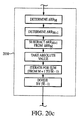
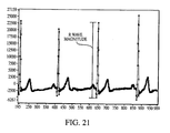
- R-wave magnitude (RM) is the peak-to-peak magnitude of the R point, which is calculated per step 2012 as shown in Fig. 20a by taking the value of the R peak (step 2014) and subtracting the value of the preceding local minimum (step 2016). If there is no local minimum found within a "back" sample or temporal window of a given size (e.g., 80 samples) per step 2018, the R point is rejected.
- Fig. 21 illustrates the calculation process graphically in terms of a typical QRS complex.
- the QR interval difference ( QR score ) and the RR interval difference ( RR score ) are determined per steps 2020 ( Fig. 20b ) and 2030 ( Fig. 20c ), respectively, as follows.
- Each lead factor is also optionally normalized, to between 0 and 1 in the illustrated embodiment.
- all of the lead magnitudes are divided by the maximum value among the leads.
- the QR score and RR score values the number are first inverted, and then normalized based upon the maximum value among the leads.
- the value are set to a small constant before inversion (or, alternatively, any other approach which accounts for the infinite value when inverting zero may be employed).
- the Assignee hereof has determined that optimal values to be used during testing are 0.01 and 0.3125 for QR score and RR score , respectively, although other values may clearly be substituted.
- the lead (vector) choice is based upon the maximum value of the sum total of the three factors for each lead.
- the leads are ranked from best to worst as: Lead 2, Lead 3, Lead 1, and Lead 4.
- the default lead order is selected based upon an ideal mean electrical axis of the heart.
- Lead 2 should, theoretically, have the largest ECG amplitude because the electrical projection onto this lead is the greatest with the electrodes 'CF' used for the ECG.
- the other rankings are determined based upon this theory, using the expected relative voltage from the lead. If two or more leads have the same score, the lead is selected based upon this ranking system.
Description
- A portion of the disclosure of this patent document contains material that is subject to copyright protection. The copyright owner has no objection to the facsimile reproduction by anyone of the patent document or the patent disclosure, as it appears in the Patent and Trademark Office patent files or records, but otherwise reserves all copyright rights whatsoever.
- The present invention relates generally to the field of biomedical analysis, and particularly to an apparatus for non-invasively determining the cardiac output in a living subject using impedance cardiography.
- Noninvasive estimates of cardiac output (CO) can be obtained using impedance cardiography. Strictly speaking, impedance cardiography, also known as thoracic bioimpedance or impedance plethysmography, is used to measure the stroke volume of the heart. As shown in Eqn. (1), when the stroke volume is multiplied by heart rate, cardiac output is obtained.

The heart rate is obtained from an electrocardiogram. The basic method of correlating thoracic, or chest cavity, impedance, ZT (t), with stroke volume was developed by Kubicek, et al. at the University of Minnesota for use by NASA, and disclosed inU.S. Reissue Patent No. 30,101 entitled "Impedance plethysmograph" issued Sept. 25, 1979. The method generally comprises modeling the thoracic impedance ZT(t) as a constant impedance, Zo , and time-varying impedance, ΔZ(t), as illustrated schematically inFig. 1 . The time-varying impedance is measured by way of an impedance waveform derived from electrodes placed on various locations of the subject's thorax; changes in the impedance over time can then be related to the change in fluidic volume (i.e., stroke volume), and ultimately cardiac output via Eqn. (1) above. - Despite their general utility, prior art impedance cardiography techniques such as those developed by Kubicek, et al. have suffered from certain disabilities. First, the distance (and orientation) between the terminals of the electrodes of the cardiography device which are placed on the skin of the subject is highly variable; this variability introduces error into the impedance measurements. Specifically, under the prior art approaches, individual electrodes 200 such as that shown in
Figs. 2a and 2b , which typically include a button "snap"type connector 202,compliant substrate 204, andgel electrolyte 206 are affixed to the skin of the subject at locations determined by the clinician. Since there is no direct physical coupling between the individual electrodes, their placement is somewhat arbitrary, both with respect to the subject and with respect to each other. Hence, two measurements of the same subject by the same clinician may produce different results, dependent at least in part on the clinician's choice of placement location for the electrodes. It has further been shown that with respect to impedance cardiography measurements, certain values of electrode spacing yield better results than other values. - Additionally, as the subject moves, contorts, and/or respirates during the measurement, the relative orientation and position of the individual electrodes may vary significantly. Electrodes utilizing a weak adhesive may also be displaced laterally to a different location on the skin through subject movement, tension on the electrical leads connected to the electrodes, or even incidental contact. This so-called "motion artifact" can also reflect itself as reduced accuracy of the cardiac output measurements obtained using the impedance cardiography device.
- A second disability associated with prior art impedance cardiography techniques relates to the detection of a degraded electrical connection or loss of electrical continuity between the terminals of the electrode and the electrical leads used to connect thereto. Specifically, as the subject moves or sweats during the measurement, the electrolyte of the electrode may lose contact with the skin, and/or the electrical leads may become partially or completely disconnected from the terminals of the electrode. These conditions result at best in a degraded signal, and at worst in a measurement which is not representative of the actual physiological condition of the subject.
- Another significant consideration in the use of electrodes as part of impedance cardiographic measurements is the downward or normal pressure applied to the subject in applying the electrode to the skin, and connecting the electrical leads to the electrode. It is desirable to minimize the amount of pressure needed to securely affix the electrode to the subject's skin (as well as engage the electrical lead to the electrode), especially in subjects whose skin has been compromised by way of surgery or other injury, since significant pressure can result in pain, and reopening of wounds.
- It is also noted that it is highly desirable to integrate cardiac output measurement capability into a compact, rugged, and efficient platform which is readily compatible with different hardware and software environments. The prior art approach of having a plurality of different, discrete stand-alone monitors which include, for example, a dedicated, redundant display and/or other output or storage device is not optimal, since there is often a need to conserve space at the subject's bedside or even in their home (e.g., in outpatient situations), as well as cost efficiency concerns. Furthermore, a plurality of discrete stand-alone monitors necessarily consume more electrical power (often each having their own separate power supplies), and require the subject or clinician to remain proficient with a plurality of different user interface protocols for the respective monitors. In many cases, the individual stand-alone monitors are also proprietary, such that there is limited if any interface between them for sharing data. For example, where two such monitors require a common parametric measurement (e.g., ECG waveform or blood pressure), one monitor frequently cannot transmit this data to the other monitor due to the lack of interface, thereby necessitating repeating the measurement.
- Recognizing these deficiencies, more recent approaches have involved the use of modular devices, wherein for example a common monitor/display function is utilized for a variety of different functional modules. These modules are generally physically mounted in a rack or other such arrangement, with the common monitor/display unit also being mounted therein. A common power supply is also generally provided, thereby eliminating the redundancy and diversity previously described. However, heretofore, impedance cardiography (ICG) equipment has not been made in such modular fashion, nor otherwise compatible with other modular devices (such as blood pressure monitoring or ECG equipment), such that such other signals can be obtained directly or indirectly from these devices and utilized within the ICG apparatus. The quality or continuity of these signals, whether obtained directly from the subject being monitored or from other modules, has not been readily and reliably provided for either.
- Typical patient monitors include modules for several physiologic measurements such as ECG, blood pressure, temperature, and arterial pulse oximetry. The addition of ICG provides the physician with additional useful clinical information about the patient.
- Furthermore, prior art ICG devices (modular or otherwise) do not provide the facility for direct transmission of the data obtained from the subject, or other parameters generated by the ICG device after processing the input data, to a remote location for analysis or storage. Rather, the prior art approaches are localized to the bedside or monitoring location. This is a distinct disability with respect to the aforementioned outpatient applications, since the subject being monitored must either manually relay the information to the caregiver (such as by telephone, mail, or visit), or perform the analysis or interpretation themselves. Additionally, it is often desirable to perform more sophisticated (e.g. algorithmic) comparative or trend analysis of the subject's data, either with respect to prior data for that same subject, or data for other subjects. The lack of effective transmission modes in the prior art to some degree frustrates such analysis, since even if the subject has the facility to perform the analysis (e.g., PC or personal electronic device with the appropriate software), they will not necessarily be in possession of their own prior data, which may have accumulated via monitoring at a remote health care facility, or that for other similarly situated subjects.
- Based on the foregoing, there is a need for an improved apparatus for measuring cardiac output in a living subject. Such improved apparatus ideally would allow the clinician to repeatedly and consistently place the electrodes at the optimal locations. Additionally, such an improved apparatus would also permit the detection of degraded electrical continuity between the electrode terminal and skin, or the electrode terminal and electrical leads of the measurement system, and be adapted to minimize the normal pressure on the subject's tissue when applying the electrodes and electrical leads. The apparatus would further be adapted to interface with other monitoring/display systems and parametric measurement modules that may be coincidently in use, and have connectivity beyond the immediate locale of the apparatus to permit the ready transfer of data to and from one or more remote locations or devices. Facility for selecting the highest quality input from a number of different sources would also ideally be provided.
- The present invention satisfies the aforementioned needs by providing an improved apparatus for measuring the cardiac output of a living subject.
- According to the invention, there is provided a cardiac output measuring apparatus, as claimed in
Claim 1. - Other inventive features are disclosed in the appendant claims and/or in the specification and drawings.
-
-
Fig. 1 is schematic diagram illustrating the parallel column model of the impedance of the thoracic cavity of a human being. -
Figs. 2a and 2b are perspective and cross-sectional views, respectively, of a prior art impedance cardiography electrode assembly. -
Fig. 3a is a plane view of a typical human thorax illustrating an exemplary placement of the electrode arrays during cardiac output measurement. -
Fig. 3b is a schematic diagram illustrating the measurement of cardiac output using the electrode arrays and current source of the present invention. -
Fig. 4 is graph of the derivative of the time-variant component ΔZ (t) of thoracic impedance as a function of time, illustrating the systole "peak" used in determining ventricular ejection time (VET). -
Fig. 5 is a logical flow diagram illustrating one exemplary embodiment of measuring cardiac output within a living subject. -
Fig. 6 is a logical block diagram illustrating one exemplary embodiment of the cardiac output measurement system of the present invention. -
Fig. 7a is an assembly diagram illustrating the construction of a first embodiment of the electrode array for use in the present invention. -
Fig. 7b is a cross-sectional view detailing the shape of the electrode terminals of the electrode array ofFig. 7a , and the construction thereof. -
Fig. 7c illustrates top and bottom perspective views of the electrode array ofFig. 7a when fully assembled. -
Fig. 7d is a perspective view of a second embodiment of the electrode array. -
Fig. 8 is a perspective view of a third embodiment of the electrode array. -
Fig. 9 is perspective view of one embodiment of a biased-jaw electrical connector as used in conjunction with the present invention. -
Fig. 10 is a logical flow diagram illustrating one exemplary embodiment of the method of evaluating electrical lead continuity. -
Fig. 11 is a graph illustrating the frequency ranges of thoracic signals for a typical adult human subject. -
Fig. 12 is a functional block diagram illustrating one exemplary embodiment of an ICG module in accordance with the invention, including the connection of the module to a communications interface/monitoring system. -
Fig. 13 is a functional block diagram illustrating the processor and patient interface boards of the ICG module ofFig. 12 , and relationship of components comprising these boards. -
Fig. 13a is a graphical representation of the impedance signal extraction process performed by an ICG module in accordance with the present invention. -
Fig. 13b is a logical flow diagram illustrating the Operating module program flow within the microprocessor of the ICG module ofFig. 13 . -
Fig. 13c is a graphical representation of one exemplary memory map used with the storage device of the processor board ofFig. 13 . -
Fig. 13d is a graphical representation of the DSP port (e.g., SPORT0) and ADC data acquisition and timing relationships of the module ofFig. 12 . -
Fig. 14 is functional block diagram illustrating the data flow within the ICG module ofFigs. 12-13 . -
Figs. 15a-c are top, rear, and front plan views, respectively, of the module ofFigs. 12-14 , configured so as to be received within an equipment rack. -
Fig. 16 is a perspective view of the module ofFigs. 12-14 , configured as a plug-in circuit card for use within a host device. -
Figs. 17a-c are top, rear, and front plan views, respectively, of the module ofFigs. 12-14 , configured as a yoke adapted for mobility and electrical interface with a monitoring device. -
Fig. 18 is a perspective view of the yoke ofFigs. 17a-c , adapted for wireless communication with the monitoring device. -
Fig. 19 is a block diagram of the module ofFigs. 12-14 , including network interface and associated data network. -
Fig. 20 is a logical flow diagram illustrating the methodology of auto-parameter (e.g., ECG) vector selection which may be performed by apparatus according to the invention. -
Fig. 20a is a logical flow diagram illustrating one exemplary method of determining the R-wave amplitude factor. -
Fig. 20b is a logical flow diagram illustrating one exemplary method of determining the QR interval difference (QRscore) factor. -
Fig. 20c is a logical flow diagram illustrating one exemplary method of determining the RR interval difference (RRscore) factor. -
Fig. 21 is a graphical representation of the R-wave amplitude calculation which may be performed by apparatus according to the invention. -
Fig. 22 is a graphical representation of the methodology for calculating the exemplary QR and RR interval difference parameters which may be performed by apparatus according to the invention. - Reference is now made to the drawings wherein like numerals refer to like parts throughout.
- It is noted that while the invention is described herein in terms of an apparatus for determining cardiac output suitable for use on the thorax of a human subject, the invention may also conceivably be embodied or adapted to monitor cardiac output at other locations on the human body, as well as monitoring cardiac output on other warm-blooded species.
- As used herein, the term "digital processor" is meant generally to include all types of digital processing devices including, without limitation, digital signal processors (DSPs), reduced instruction set computers (RISC), general-purpose (CISC) processors, microprocessors, and application-specific integrated circuits (ASICs). Such digital processors may be contained on a single unitary IC die, or distributed across multiple components.
- As used herein, the terms "monitor" and "monitoring device" are used generally to refer to devices adapted to perform monitoring, display, user interface, and/or control functions. Such devices may be dedicated to a particular function, or multi-purpose devices adaptable to performing a variety of functions and/or interfacing with a number of functional modules.
- Referring now to
Figs. 3a-5 , the general methodology of measuring cardiac output in a living subject is described. - As previously discussed, the thoracic impedance ZT (t) of a living subject may be modeled as comprising a constant impedance, Zo , and time-varying impedance, ΔZ(t). According to the well-known "parallel-column" model of the thorax, this change in thoracic impedance, ΔZ (t), is related to the pulsatile blood volume change. In this model, illustrated in the form of a schematic diagram in
Fig. 1 herein, effectively constant tissue impedances such as bone, muscle, and fat are modeled as a conductingvolume Z o 102 in parallel with the pulsatile impedance of the blood ΔZ (t) 104. Thissecond impedance 104 is a time-varying fluid column with resistivity, p, cylindrical length, L, and a time-varying cross-sectional area that oscillates between zero and a value A, the latter which correlates to the stroke volume V. When the pulsatile volume is at a minimum in the cardiac cycle, all the conducting tissues and fluids are represented by Zo . During the cardiac cycle, the cylinder cross-sectional area increases from zero until the cylinder's volume equals the blood volume change. - Because Zo is much greater than ΔZ(t), the relationship of Eqn. (2) holds:

where L is the distance between the measurement electrodes in cm (Fig. 3a ), VET is the ventricular ejection time in seconds, and
impedance derivative 400 is purposely inverted as shown inFig. 4 so that the original negative minimum change will appear as apositive maximum 402,
- The ventricular ejection time (VET) is estimated from features in the impedance waveform, which is obtained from the measurement terminals of the
electrode arrays Figs. 3a and 3b . In the present embodiment, a value of 150 ohm-cm is used for the resistivity of the blood, although it will be recognized that other values may be substituted as appropriate. - It is noted that the description of the volume of participating tissue may be modified. Rather than model the thorax as a cylinder as shown in
Fig. 1 above, the thorax may instead be modeled as a truncated cone (as first described by Sramek and Bernstein). This approach results in a modified stroke volume calculation as in Eqn. (3):
With either of the two aforementioned approaches (i.e., cylindrical or truncated cone), the pulsatile impedance is estimated using Ohm's law, which is well known in the electrical arts. Specifically, current from a constant current source, IT(t), is applied, and the resulting voltage, VT(t), is measured in order to calculate the ratio of Eqn. (4):
In the selected frequency range (i.e., 68 kHz), the typical impedance associated with a human subject's skin is 2 to 10 times the value of the underlying thoracic impedance ZT (t). To aid in eliminating the contribution from skin and tissue impedance, the present invention may use at least two, and typically fourelectrode arrays Fig. 3a . The physical construction and these electrode arrays is described in detail with reference toFigs. 7a-8 herein. - In a simple application, one
electrode array 302 comprising astimulation electrode terminal 310 and ameasurement electrode terminal 312 is applied above thethorax 300 of the subject, while a second electrode array 304 (havingstimulation electrode terminal 314 and measurement electrode terminal 316) is applied below thethorax 300. The AC current from the current source is supplied to thestimulation electrode terminals Figure 3b , current flows from eachstimulation electrode terminal measurement electrode terminal 312, 316. The voltages at themeasurement electrode terminals 312, 316 are measured and input to a differential amplifier to obtain the differential voltage, VT(t). The desired thoracic impedance, ZT(t), is then obtained using the relationship of Eqn. (4). - As shown in
Fig. 3a , two sets of electrode arrays may advantageously be used to monitor the impedance associated with the left and right portion of thethorax 300 in the present invention. When eight electrode terminals (fourarrays 
-
Fig. 5 illustrates the logical flow of the method of measuring cardiac output which may be performed by apparatus according to the invention. As shown inFig. 5 , themethod 500 generally comprises first providing a plurality of electrode "arrays" of the type previously described herein perstep 502. The electrode arrays are positioned at predetermined locations above and below the thoracic cavity perstep 504, as illustrated inFig. 3a herein. In one embodiment of the method, these locations are chosen to be on the right and left sides of the abdomen of the subject, and the right and left sides of the neck. These locations, with prior art band electrodes, were first used by Kubicek. Other locations and/or combinations of arrays may be substituted with equal success. - Next, a substantially constant AC current is generated in
step 506, and the current applied to thestimulation electrode terminal step 508. The voltage generated at themeasurement electrode terminal 312, 316 of each electrode array is next measured instep 510. As previously discussed, this voltage is generally reduced from that applied to the stimulation electrode by virtue of the impedance of, inter alia, the thoracic cavity. Note that the measured voltage may be absolute, or relative (i.e., a differential voltage) as desired. Next, instep 512, the cardiac stroke volume from the measured voltage, using for example the relationship of Eqn. (3) above. Cardiac rate (step 514) is also determined by using the measurement electrodes to sense the ECG potentials generated by the heart of the subject. Lastly, instep 516, cardiac output is determined based on the stroke volume determined instep 512 and the cardiac rate instep 514 using the relationship of Eqn. 1 above. - Referring now to
Fig. 6 , a first embodiment of the apparatus for measuring cardiac output using the above-described technique is disclosed. In addition to the fourelectrode arrays system 600 generally comprises an alternating current (AC)current source 604 capable of generating a substantially constant current, a plurality of electrical leads in the form of a multi-endedlead assembly 606 for connecting the instrument monitor 607 to the individual terminals of theelectrode arrays processor 608 with associated algorithms capable of running thereon for performing analysis of the signals measured from the measurement terminals, data andprogram memory processor 608 for storing and retrieving program instructions and data; an I/O interface 611 (including analog-to-digital converter) for interfacing data between the measurement electrodes and theprocessor 608; amass storage device 612 in data communication with the processor for storing and retrieving data; a display device 614 (with associated display driver, not shown) for providing an output display to the system operator, and aninput device 616 for receiving input from the operator. It will be recognized that theprocessor 608,memory O interface 611,mass storage device 612,display device 614, and input device 616 (collectively comprising the instrument monitor 607) may be embodied in any variety of forms, such as a personal computer (PC), hand-held computer, or other computing device. The construction and operation of such devices is well known in the art, and accordingly is not described further herein. - The applied current derived from the
current source 604 is a 70 kHz sine wave of approximately 2.5 mA peak-to-peak. The measured voltage associated with the aforementioned sine wave is on the order of 75 mV peak-to-peak. These values are chosen to advantageously minimize electric shock hazard, although it will be appreciated that other frequencies, currents, or voltages may be substituted. The construction and operation of AC current sources is well known in the electronic arts, and accordingly is not described further herein. - The
electrode lead assembly 606 of the illustrated embodiment contains a ten wire assembly (two wires are left unused) that branches to eightindividual connectors 606a-h. Theconductors 613a-j of the lead assembly are fashioned from electrically conductive material such as copper or aluminum, and are insulated using a polymer-based insulation having the desired dielectric strength as is well known in the electrical arts. The length of the conductors may also be controlled so as to match the impedance of each individual conductor to that of the others within theassembly 606. - Using one of four modified lead configurations, the body surface potential is measured between two measurement electrodes. This time-varying voltage reflects the electrical activity of the heart, and contains one QRS interval per cardiac cycle. The biopotential is analyzed to identify each QRS complex. The frequency of QRS complexes determines the heart rate. The Q wave within the QRS complex is then used to trigger identification of VET within the

- Additional embodiments of the cardiac output measurement apparatus of the invention are described subsequently herein with respect to
Figs. 11-22 . - Referring now to
Figs. 7a-7c , theelectrode arrays Fig. 7a , each array comprises aflexible substrate 704 having a plurality ofapertures terminals top portions substrate 704. The twoterminals stimulation terminal 310 andmeasurement terminal 312 as previously described with respect toFig. 3a . Thestimulation terminal 310 is used to apply the potential necessary to generate the current flowing through the thoracic cavity of the subject. It will be noted that despite designation of one terminal as a "stimulation terminal" and one as a "measurement" terminal, the role of these terminals may be reversed if desired, since they are functionally and physically identical but for the potential applied thereto (or measured therefrom). It is noted that the asymmetric shape of thesubstrate 704 of the embodiment ofFigs. 7a-7c may be used to assist the clinician in rapidly determining which electrode is the stimulation electrode and which the measurement electrode, such as by assigning a convention that the end of the array having a given shape always contains the stimulation electrode. Additionally, the substrate may be shaped to adapt to certain physical features of the patient, such as by using a substrate having a broader width so as to better conform to the generally cylindrical shape of the subject's neck. Any number of different substrate shapes may be employed;Fig. 7d illustrates one such alternative shape. - As shown in
Figs. 7a-7c , theterminals substrate 704 at a predetermined distance 705 by a mountingelement 707 or any one of a variety of other constructions as will be described in greater detail below. The distance (measured centerline-to-centerline on theterminals 310, 312) is approximately 5 cm in the embodiment ofFig. 7a , although it will be recognized that other distances may be substituted. Desired distances may be determined through experimentation, anecdotal observations, calculations, or any other suitable method; however, experimental evidence obtained by the Applicant herein indicates that a distance of 5 cm is optimal for impedance cardiography measurements. - The
substrate 704 in the embodiment ofFig. 7a is formed from a Polyethylene foam, although other materials such as cloth or vinyl may be substituted. The polyethylene foam is chosen for its compliance and flexibility, thereby allowing it to conform somewhat to the contours of the subject's anatomy, while still maintaining sufficient rigidity for maintaining theterminals - As shown in
Fig. 7b , theterminals sidewall portion 720 having afirst diameter 722, and atop portion 724 having asecond diameter 726, thesecond diameter 726 being greater than thefirst diameter 722 in order to assist in retaining a connector mated to the terminal 310, 312 as described in greater detail below. Theouter wall 721 of thesidewall portion 720 is essentially vertical in orientation (i.e., parallel to thecentral axis 725 of the terminal 310, 312), while the top portion is progressively rounded as shown. The terminals may be manufactured from an extruded metal such nickel, with a coating of brass, or may be molded from carbon. Alternatively, the terminals may be molded of plastic, and coated with a metal such as gold or impregnated with carbon. The extruded metal possesses the advantage of low cost, while the molded plastic impregnated with carbon possesses the advantage of radiolucency. A terminal molded of plastic and coated with gold may possess low noise artifact. - The
terminals terminal element 730 and a lowerterminal element 732 as shown inFigs. 7a and 7b . Thepost 734 of the lowerterminal element 732 is adapted to be frictionally received within the cavity 736 of the upper terminal element when the two components are mated. In this fashion, the upper andlower elements element 707 being frictionally held or "pinched" between thelower surface 740 of theupper element 730 and theupper surface 742 of thelower element 732. Thepost 734 of the lower element perforates the mountingelement 707, or alternatively penetrates through apre-existing aperture 738 formed therein. Thelower elements electrode array terminals - The
electrolytic element 750 of each electrode array comprises an electrolytic gel of the type well known in the bio-electrical arts; in the present embodiment, the gel comprises an ultraviolet (UV) cured potassium chloride (KCl) gel, although it will be recognized that other types of compounds or materials may be used. UV curing of the gel allows theelement 750 to have a more solidified consistency and improved mechanical properties, thereby preventing excessive spreading or thinning of the element when the array is applied to the subject while still maintaining its overall adhesiveness and electrolytic properties. As shown inFigs. 7b and7c , theelement 750 is sized so as to encompass the edges 752 of therespective aperture substrate 704 over which it is placed when assembled, although other configurations may be used. The top portion 755 of theelement 750 fits at least partially within theaperture terminal element 732. In this way, ions are passed between the skin of the subject and the terminals of the array via thegel element 750. The gel also provides for adhesion of the array to the skin of the subject, although the array of the present embodiment also includes a separate adhesive 762 which is applied to the bottom surface of thesubstrate 704, as shown inFig. 7c . - Since the placement of the
electrolytic element 750 with respect to theterminals element 750 is advantageously placed in the embodiment ofFigs. 7a-c so as to be symmetric with respect to the terminal 310, 312. It will be recognized, however, that the element(s) 750 may also be placed so as to produce certain desired electrolytic conditions. Similarly, theelement 750 may be split into two or more component parts if desired. - Furthermore, it is noted that while the embodiment of
Figs. 7a-c employs two fixed terminals that are effectively immovable within the substrate, means for allowing adjustment or change of the relative position of the terminals may be substituted. For example, as illustrated inFig. 8 , a terminal array having three terminal posts may be used, thesecond post 802 being spaced afirst distance 804 from thefirst post 806, and thethird post 810 being spaced asecond distance 808 from thefirst post 806, such that the clinician can select one of two terminal spacings as desired. - As illustrated in
Fig. 9 , each electrodelead assembly connector 606a-h is designed to mitigate the downward force required to mate the connector with its respective electrode array terminal. Specifically, eachconnector 606a-h contains two spring-biasedconductive jaws 902 that are spread apart by thecam surface 904 of anactuator button 906 disposed on thefront 907 of theconnector body 908. Theconnector jaws 902 and bias mechanism are designed to allow the upper andsidewall portions electrode terminal 310, 312 (Fig. 7b ) to be received within therecess 910 of thejaws 902 when thebutton 906 is fully depressed. In this fashion, effectively no downward force is required to engage the connector to its respective terminal. Thejaws 902 are contoured to engage substantially the entire surface of thesidewall portion 720 of the terminal when theactuator button 906 is released. Since thesidewall portion 720 of the terminal is effectively circular in cross-section, the connector may advantageously rotate around the axis of the terminal 310, 312 when lateral tension is applied to the conductor attached to that connector.U.S. Patent No. 5,895,298 issued April 20, 1999 , entitled "DC Biopotential Electrode Connector and Connector Condition Sensor," and incorporated herein by reference in its entirety, describes a bias jaw electrical connector of the type referenced above in greater detail. - When used with the four two-
terminal electrode arrays Fig. 3a , eachconnector 606a-h is fastened to one of the twoterminals O device 611 of thesystem 600 via the electrical conductors and connectors associated with the stimulation electrode terminals, the stimulation electrode terminals themselves, the thorax of the subject, the measurement terminals, and the electrical conductors and connectors associated with the measurement terminals. - Referring now to
Fig. 10 , the method of evaluating the electrical continuity of one or more leads within the system is described. Note that while the following description is based on the two-terminal array configuration (Figs 7a-7c ) and the use of four arrays as shown inFig. 3a , the method may be applied to many alternate configurations with equal success. - First, in
step 1002, the electrode arrays are disposed on the skin of the subject. The position at which the electrode arrays are disposed on the subject are measured in relation to the thoracic cavity as illustrated inFig. 3a , or alternatively may be inferred by the weight and height of the subject. Next, a current is generated between the stimulation electrodes and the measurement electrodes of the respective arrays instep 1004. As previously discussed, the current passes through at least a portion of the subject's thoracic cavity, encountering a time-variant impedance therein. - An impedance waveform is then measured from two or more of the measurement terminals of the arrays in
step 1006. The waveforms comprise measurements of impedance as a function of time, which is well known in the cardiographic arts. These measured waveforms are then compared to one another instep 1008 to detect changes or variations between them. In the present embodiment, two waveforms are differenced by way of a simple differencing algorithm resident on theprocessor 608 of the system 600 (Fig. 6 ), although it will be recognized that other approaches may be used. For example, the base impedance may be calculated for the left and right sides. The larger base impedance may then be subtracted from the smaller base impedance, with this difference then divided by the smaller impedance. The resulting percentage ratio, when greater than a predetermined threshold value, may represent the presence of detached or loose electrodes. While some variation between the waveforms is normal, significant variations are indicative of either a degraded electrical connection, such as between the electrode array terminal and its respective connector, or between the electrolytic gel and the skin of the patient, or even the gel and the terminal of the array or between the cable and connector. A threshold value is determined and set by the operator of the system instep 1010 such that when the threshold "difference" is exceeded as determined by the aforementioned algorithm (step 1012), the operator will be alerted to the degraded condition such as by a visual or audible alarm instep 1014. - In another embodiment of the method, the difference in impedance (or voltage) between the
individual terminals terminal 310 with respect to anotherterminal 312 of the exemplary two-terminal array 302 illustrated herein is measured; when this value exceeds a certain threshold difference value (e.g., 650 Ohms, although other values may be substituted based on any number of factors), a loose electrode or otherwise degraded connection is suspected. It will be recognized that this methodology may also be employed when more that two electrical terminals are electrically connected to the system. For example, if three electrodes (e.g.,electrodes - It will be recognized by those of ordinary skill that other approaches may be utilized for analyzing the impedance (voltage) measurements obtained from the electrode arrays in evaluating electrical continuity. Furthermore, it will be recognized that the aforementioned threshold value may be algorithmically determined and/or parametrically variant. For example, based on data obtained by the system before and/or during operation, the apparatus of the present invention may periodically or continuously calculate new threshold values as a function of time. Alternatively, the system may be adapted to calculate a plurality of such impedance difference values across each of the terminal arrays in use, and average the values periodically to maintain a "moving average" of impedance differences. As yet another alternative, other physiological parameters of the subject being monitored could be used as "triggers" for revised threshold determination and/or impedance difference calculation.
- It is noted that the use of the multi- terminal electrode arrays having predetermined and substantially equal terminal spacing as previously described allows such comparisons between electrode waveforms to be made; errors resulting from uncontrolled spacing of the terminals are effectively eliminated. Using prior art electrodes, the aforementioned method would be largely ineffective, since these error sources would force the threshold value to be set artificially high, thereby potentially masking conditions of degraded electrical continuity which could affect the ultimate accuracy of and cardiac output estimation made by the system.
- Referring now to
Figs. 11-14 , the improved impedance cardiography module which may be used with the present invention is described. The ICG module utilizes the electrical bioimpedance measurements previously described herein to continuously generate a signal indicative of pulsatile thoracic impedance changes. This pulsatile thoracic impedance signal is processed to produce signals indicative of other related parameters, such as the ventricular ejection time (VET) and the maximum rate of change of pulsatile thoracic impedance, which are used to calculate the volume of blood pumped per stroke according to equations previously discussed. While described specifically in terms of the BioZ® ICG module manufactured by the Assignee hereof, it will be appreciated that the broader inventive concepts disclosed herein may be embodied in any number of different forms and combinations of functionality, several of which are described subsequently herein as alternate embodiments. - As previously discussed, the voltage developed across the thoracic impedance at any instant in time can vary due to a number of different factors. Specifically, the voltage is affected by four primary components: (i) base impedance; (ii) respiration; (iii) cardiac changes; and (iv) patient motion.
- The base impedance comprises the largest component of the modulated waveform, and represents the nominal conductivity of the thorax. It is a function of the tissue and fluid distribution within the interrogated area. The average value of the base impedance, or TFI, is roughly 30 Ohms, but can vary from 5 to 60 Ohms in adult humans.
- Inhalation and expiration by the patient causes significant impedance changes as gases enter and exit the lungs. The ventilation cycle is relatively long, typically 0.2 to 0.7 Hz with variable magnitude.
- Impedance changes occur due to the cardiac cycle, such as after ventricular depolarization (QRS complex), and have very small magnitudes (approximately 0.05 - 0.3 Ohms). These impedance changes are the result of aortic expansion after blood is ejected from the ventricle, and contraction as blood is flows into the circulatory system.
- Movement by the patient causes significant impedance changes due to fluid shifts and density/volume changes in the thorax, with varying frequency and magnitude. The motion component of impedance is effectively eliminated when the patient is monitored at rest.
-
Fig. 11 is a graph illustrating the frequency ranges of these four signal components for a typical adult human subject. - The ICG module advantageously addresses the foregoing components of thoracic impedance through its signal processing circuitry and algorithms, now described in detail.
- As shown in
Fig. 12 , theICG module 1200 is electrically coupled to thehost monitor 1202 via the interface device 1204. TheICG module 1200 generally comprises amicroprocessor 1206,storage device 1208, anddigital signal processor 1210, as described in greater detail below with respect toFig. 13 . Themodule 1200 communicates with ahost monitor 1202 to continuously monitor and display the cardiac output and pulse rate of the subject under evaluation. Communications are in the illustrated embodiment conducted according to a predetermined protocol (such as a serial interface protocol of the type well known in the art), although other approaches may be substituted with equal success. The module further includes other features such as input power conditioning and "soft-start" current limiting functionality, software/firmware download from the host device, and electrical isolation (e.g., 4000 V) for the subject being monitored. - As shown in
Fig. 13 , the exemplary embodiment of themodule 1200 comprises twocomponent boards patient board 1302 provides a number of functions, including (i) interface with the external signal sources; e.g., the patient leads and electrodes which provide, inter alia, the impedance and ECG waveform signals to the module; (ii) ECG vector select (described in greater detail below); and (iii) input signal filtration, conditioning, and domain conversion. Thepatient board 1302 also isolates the electrical (ECG) the mechanical (ΔZ) components of cardiac activity from each other, and from the components of respiration and motion present in the signals derived from the subject under evaluation. A first high-pass filter (pole at 0.33 Hz) 1306 filters theinput impedance waveform 1307 andECG waveform 1308. Band-pass filters Fixed gain amplifiers pass filters digital potentiometers filters filter units - The
patient board 1302 further comprises a plurality ofECG inputs 1314 which are obtained from the aforementioned electrode pairs and input to a crosspoint switch 1315 (e.g., a 16 x 16 analog multiplexer such as the AD75019 device manufactured by Analog Devices), which selects the best "quality" input from among the four inputs as described in detail below with respect toFigs. 20-22 . The selected ECG signal is low-pass filtered 1316, amplified to a fixedgain 1317, high-pass filtered 1318, and then supplied (via 1 M Ohm resistor) to theECG ADC 1319. The threeADCs DSP 1210 on theprocessor board 1304, described below. - The
patient board 1302 also uses this crosspoint switch to provide several other functions, including connection of leads to the patient, provision of multiple ECG vectors, loose electrode testing (previously described), cable identification, and calibration. - The
processor board 1304 comprises a digital signal processor (DSP) 1210 with direct memory access (DMA) of the type well known in the electronic arts, amicroprocessor 1206, astorage device 1208 coupled with theDSP 1210 andmicroprocessor 1206 via a data bus, a first signal (constant current)source 1330 generating a nominal 70 kHz output signal, asecond signal source 1332 generating a nominal 2 MHz output signal, a clock signal generator (12 MHz nominal), and digital-to-analog converter (DAC) 1334. - In one variant, the module is configured with a DC/DC converter operating at 90 kHz, and the aforementioned ICG current source at 70 +/- 6 kHz.
-
Fig. 13a graphically illustrates the impedance signal extraction process performed by theICG module 1200. - In the illustrated embodiment of
Fig. 13 , themicroprocessor 1206 comprises a microcomputer running at a crystal frequency of approximately 32.7 KHz, although it will be recognized that other platforms may be substituted with equal success. The system clock is generated by an on-chip phase-locked loop (PLL) and is software programmed for an operating frequency of 16 MHz. The device is operated in the 8-bit bus operating mode with all data transfers occurring ondata lines 8 through 15. The processor also has a QSPI built in, which in the present embodiment is used for communications to the host device, such as by using a serial interface protocol of the type previously referenced herein. - The
ICG module 1200 utilizes a three-part software architecture comprising three modules: (i) "Initialization" module; (ii) "Operating" module; and (iii) "Processing" module. Any one of the three software code modules can be independently downloaded. - The Initialization operating system of the
microprocessor 1206 comprises a variant of the "C Executive" system manufactured by JMI Software Consultants, Inc., although it will be recognized that other operating systems may be substituted. C Executive comprises a real-time, memory-resident, event driven monitor program designed for embedded systems which require multi-tasking functionality and ROM storage. The initialization module software uses the initialization OS for process scheduling, input and output, and inter-process communication. - The processor Operating code does not use any operating system. Upon booting, the microprocessor registers are set for proper operation. Chip selects, interrupts, internal memory, stack pointer and initial program counter are all the responsibility of the Operating module's boot process.
Fig. 13b graphically illustrates the high-level program flow of the Operating software module of the illustrated embodiment. - The processing module executes the bioimpedance algorithms. It also controls peripheral functions, such as the gain of the impedance amplifiers, the setting the ECG vector, reading of the impedance and ECG A/D converters, and detection of electrical continuity. The
DSP 1210 adapted for use with the invention comprises an Analog Devices ADSP-2181 device, although it will be recognized that any digital processing device adapted for algorithms such as those described herein may be used with proper adaptation. For example, members of the Texas Instruments 'C4x family of floating point DSPs, 'C5x family of fixed point processors, 'C6x family of VLIW processors, the Lucent DSP 16000 family, or even a user-customized processor core or ASIC may be used. Many other types of digital signal processors exist, any number of which may be adapted for use with the present invention. - Parameters determined from the digitized data are communicated to the
microprocessor 1206 via thestorage device 1208, specifically by writing data words to predetermined locations within the storage device. In the present embodiment, a dual-port RAM (DPR) is selected to allow dual-port access and two-way communication by the DSP 1210 (via, e.g., the BDM port) andmicroprocessor 1206 via first and second memory ports, respectively; however, it will be recognized that other types and configurations of storage device including DRAM, SDRAM, SRAM, dual data rate synchronous DRAM (DDR-SDRAM), ROM, or even non-semiconductor storage devices may be substituted. The embodiment ofFig. 13 further comprises a DMA unit of the type well known in the art, thereby facilitating direct memory accesses by the processor(s). Themodule 1200 is further configured such that address and data bus interfaces exist between themicroprocessor 1206 andstorage device 1208, and between theDSP 1210 andstorage device 1208, thereby providing for memory addressing and data transfer by both processors.Fig. 13c illustrates one exemplary embodiment of the memory map used with theDPR 1208 of the ICG module. - An address range is also specified at the
microprocessor 1206 and connected to the DSP'sDMA port 1350 for DSP code download from the microprocessor 1206 (and host 1202) to theDSP 1210 during operation. - The impedance and ECG waveform data present within the module consists of all measured and calculated parameters related to a specific cardiac event, without any averaging. The start of data is placed at the Q point of the cardiac cycle measured. Waveform data is stored in the order shown in Table 1:
Table 1 Byte Value Description 0 Start_data Framing byte = 0xff 1 Error_status Error codes for cardiac cycle 2 DSP Version integer XX.00 3 DSP Version fraction 0.XX 4 ECG full scale range MSB 5 ECG full scale range LSB 6 ΔZ full scale range MSB 7 ΔZ full scale range LSB 8 R - R interval MSB Ms 9 R - R Interval LSB 10 PEP MSB Ms 11 PEP LSB 12 LVET MSB Ms 13 LVET LSB 14 Predicted LVET MSB Ms 15 Predicted LVET LSB 16 Base Impedance MSB Ω x 100 17 Base Impedance LSB 18 Integral MSB ΔZ integral * 100000 19 Integral LSB 20 Baseline MSB ΔZ baseline value for Integral 21 Baseline LSB 22 
value* 10000 23 
24 
value* 1000 25 
26 Ideal Weight MSB Kg x 100 27 Ideal Weight LSB 28 R wave dv/dt detection threshold MSB Samples 29 R wave dv/dt detection threshold LSB 30 Pacer dv/dt detection threshold MSB Samples 31 Pacer dv/dt detection threshold LSB 32 Gender 0 = male, 1 = female 33 Height Cm 34 Weight Kg 35 Body frame 0 = small, 1 = medium, 2 = large 36 Age Years 37 MAP MmHg 38 Systolic Pressure MmHg 39 Diastolic Pressure MmHg 40 CVP MmHg 41 PAOP MmHg 42 Display Update Rate 1 - 60 cycles 43 Cycle Averaging 1 - 60 cycles 44 ECG Vector 0 = EF, 1 = CF, 2 = DF, 3 = ED 45 Waveform Buffer Configuration 46 Demo Waveform Flag 0 = OFF, 1 = ON 47 Pacer Detection 0 = OFF, 1 = ON 48 Electrode configuration 0 = average, 1 = left, 2 = right 49 End data Framing byte = 0xff - So-called "live" waveform data is written into
memory 1208 at a predetermined rate and at predetermined addresses to facilitate subsequent analysis; Table 2 illustrates the data write operations into memory performed by theDSP 1210 at a 200Hz rate:Table 2 Data Memory address Description ΔZ 7FA0 ECG 7FA2 Respiration 7FA4 dZ/dt 7FA6 pacer impulse 7FA8 Pace enhanced ECG 7FAA ECG + pacer spikes ECG gain factor 7FAC Loose Electrode 7FAE - The
module 1200 further utilizes a 512K x 8 static RAM (SRAM) array for temporary data storage. The static RAM is also used as temporary storage of ICG Monitor program code during program download of the software. The program code is stored in a 128K x 8 sectored "flash" EPROM. This device can be erased on an individual sector basis. The first sector of the flash memory is used for storing the initialization (boot-up) code. In general, this sector of code is not modified, thereby ensuring that even if a download of code fails, the module will still be able to attempt another download. The other seven sectors of the flash memory are used for storage of the Operating code. As previously described below, the Operating code is the code which is run during normal operation of the module. This code can be updated using the host monitor or other external storage device. - The
DSP 1210 of the present embodiment is also configured to receive a variety of useful data from the host/interface, as set forth in Table 3 below:Table 3 Data Example DPR address Description Gender 3F50 0x0000 = male 0x0001 = female Height 3F52 Centimeters Weight 3F54 Kilograms Body Type 3F56 0x0000 = small 0x0001 = medium 0x0002 = large Age 3F58 Years MAP 3F5A MmHg Systolic 3F5C MmHg Diastolic 3F5E MmHg CVP 3F60 MmHg PAOP 3F62 MmHg - Other ports on the
DSP 1210 are used for various functions in the module. For example, the SPORT0 is a standard port of the DSP which is used to transmit setup control to theADCs digital potentiometers DAC 1334.Fig. 13d graphically illustrates the SPORT0 and ADC data acquisition and timing relationships of the present embodiment in detail. -
Fig. 14 illustrates portions of the data and signal flow within and between the patient and processor boards (and associated components) of the ICG module ofFigs. 12-13 . - Appendix I hereto provides a listing of the various parameters utilized within or generated by the
ICG module 1200. Note that the VEPT (Volume of Electrically Participating Tissue) and BSA (Body Surface Area) are, according to the present methodology, determined using the sex, height and weight of the patient measured, although other approaches may be substituted. Hemodynamic parameters are calculated from the values HR, PEP, VET, TFI,


- Appendix II details the communications protocol (including memory address) for the patient data communicated by the exemplary embodiment of the module to the host device.
- Two important parameters present in estimations of cardiac output are (i) the maximum negative change in the impedance signal (Z(t)) as a function of time,


- In addition to the foregoing "B", "C", and "X" points, the so-called "O point" may be of utility in the analysis of the cardiac muscle. The O point represents the time of opening of the mitral valve of the heart. The O point is generally determined as the time associated with the first peak after the X point. The time difference between aortic valve closing and mitral valve opening is known as the iso-volumetric relaxation time, IVRT.
- Impedance cardiography further requires recording of the subject's electrocardiogram (ECG) in conjunction with the thoracic impedance waveform previously described. Processing of the impedance waveform for hemodynamic analysis requires the use of ECG fiducial points as landmarks. Processing of the impedance waveform is generally performed on a beat-by-beat basis, with the ECG being used for beat detection. In addition, detection of some fiducial points of the impedance signal may require the use of ECG fiducial points as landmarks. Specifically, individual beats are identified by detecting the presence of QRS complexes within the ECG. The peak of the R wave (commonly referred to as the "R point") in the QRS complex is also detected, as well as the onset of depolarization of the QRS complex ("Q point"). In patients with a pacemaker, the natural process of ventricular depolarization is either supplemented or entirely overridden.
- Accordingly, in another embodiment, the ICG module for use in the present invention is further modified to incorporate fiducial point detection within the aforementioned impedance and/or ECG waveforms provided as inputs to the module. Specifically, "event markers" are placed within the waveform buffers to indicate the algorithm detection points with reference to the waveform samples. Table 4 below shows some of the marker values used for the various fiducial points:
Table 4 Fiducial Point Marker Value Q point 0x10 B point 0x20 X point 0x30 dZ/dt max 0x50 d2Z/dt2 max 0x60 - The difference between each detected X and B point is used to calculate ventricular ejection time (LVET). The magnitude of the largest negative derivative of the impedance change occurring during systole (dZ/dtmax) is calculated from the C point. LVET and dZ/dtmax are then used to calculate the stroke volume, from which cardiac output (CO) is derived.
- In yet another variant, fiducial point detection within the ICG module is conducted using the wavelet transform methodology as disclosed in co-pending U.S. patent application publication number
US 20020138014 . The fiducial points of the ΔZ and dZ/dt waveforms (e.g., B, C, X, and O) are detected in this variant using discrete wavelet transforms, rather than by empirical detection, which is based on processing features in the first and second derivatives of ΔZ(t). The wavelet transform methodology advantageously requires only simple additions and multiplications of real numbers, thereby substantially simplifying the processing associated with the cardiac output (CO) determination performed by theDSP 1210 and associated algorithms. Furthermore, the wavelet transform methodology, compared to the empirical methodology, is much less sensitive to noise artifact. - Similarly, fiducial points are utilized in evaluating the electrocardiogram (ECG) waveform of the subject, with specific individual "beats" of the subject's cardiac muscle being identified through detection of one or more fiducial points, either by the aforementioned wavelet transforms or by other means. The peak of the R wave (R point) in the QRS complex as well as the onset of depolarization of the QRS complex (Q point) are also detected. The time interval between the R waves is also used to calculate the subject's heart rate.
- Referring now to
Figs. 15a-c , one embodiment of the ICG module for use in the present invention adapted for rack mounting is described. As shown inFig. 15 , themodule 1500 is fitted with afaceplate 1502 disposed generally at thefront portion 1506 of themodule housing 1504, as well as a plurality ofelectrical connectors connector 1510 disposed generally at thefront portion 1506 of the housing, and oneconnector 1512 at therear portion 1515 of thehousing 1504. A debug port connector (not shown) is also provided to facilitate debug of themicroprocessor 1206. Optionalmodule status indicators 1520 are also disposed on thefaceplate 1502 so as to be viewable by a user or clinician during operation of the module when the module is received within an equipment "rack" (described in greater detail below). In the illustrated embodiment, themodule housing 1504 is shaped and sized so as to be received within the rack adjacent or generally in proximity to other modules, such that space is economized. - The
front panel connector 1510 comprises the ICG module interface with the patient being monitored, including electrical connection to the measurement and stimulation electrode terminals previously described herein. Thefront panel connector 1510 may be of any configuration, such as a multi-pin standardized male or female electrical connector of the type well known in the art, although literally any configuration (proprietary or otherwise) may be substituted. - The
rear panel connector 1512 allows for electrical connection of the module to the host monitor/interface unit, such as for example via a multi-pin female connector for mating with backplane connectors of the host monitoring equipment (including any voltage supply associated therewith). It will be recognized, however, that other types and "pin-outs" of connector or data/power interface may be substituted with equal success, dependent primarily on the host equipment with which the module must interface. - The
equipment module 1500 ofFig. 15 may also be configured with a network data interface (described in detail below with respect toFig. 19 ), thereby allowing the distribution of data to a plurality of different local and/or remote nodes for analysis, storage, or other functions. -
Fig. 16 illustrates yet another embodiment of the ICG module for use in the invention, configured as a plug-incircuit card 1600 for use within a host device such as a dedicated stand-alone monitor or host monitoring device (e.g., one that has a primary function which may or may not be related to ICG or cardiography), personal computer, laptop computer, hand-held computer, minicomputer, or SUN UNIX workstation. Thecircuit card 1600 integrates all of the functionality of the embodiment of Fig. 1300, including processor and patient interface boards, onto onecard substrate 1602. A standardized edge-typeelectrical connector 1604 is also provided to permit interface with the card receptacle of the host device (not shown), which may be configured according to any electrical interface standard (such PCMCIA, PC Card, or otherwise). - In yet another embodiment (not shown), the ICG module for use in the invention comprises a card generally similar to that shown in
Fig. 16 , except that the edge-type connector 1604 is replaced with a ribbon-cable and associated connector (or other type of connector) of the type well known in the electrical arts for interfacing the module with other circuit elements and boards within the host device. As yet another alternative, the ICG module may be plugged directly into another module within the host device. It will be recognized that literally any type of electrical interconnection scheme and protocol between the ICG module (whether in "card" form as inFig. 16 or otherwise) and the host device with which the module is used may be employed consistent with the invention. -
Figs. 17a-c illustrate yet another embodiment of the ICG module, configured as a "yoke" 1700 adapted for mobility and electrical interface with a monitoring device. As used herein, the term yoke is meant to include any configuration of mobile or transportable device which is used to facilitate centralization of a plurality of patient signals. In the present embodiment, theyoke 1700 is adapted to receive a plurality of electrical leads 1702 (whether as individual leads, in one variant, or as a single multi-terminalelectrical connector 1708, in another variant) which are connected to theelectrodes 1704 disposed on the thorax of the patient being monitored. Theyoke 1700 is configured to be light weight and rugged, and utilizes a molded plastic impact-resistant housing 1706 of the type well known in the polymer arts, although other materials may be used. Theyoke housing 1706 contains the electronics of the ICG module, including processor and patient interface boards (not shown), and further optionally includes anLED 1710 or other status indication for the ICG module. The output of the ICG module electronics in theyoke 1700 is transferred to the monitoring device (not shown) via adata interface 1712, in the present embodiment a universal serial bus (USB) connection and cable of the type well known in the electrical arts. This USB interface advantageously allows theyoke 1700 to interface data with any number of different types of devices, each of which include their own USB interface. - Alternatively, a wireless interface between the
yoke 1700 and host monitor (or for that matter, between theyoke 1700 and the patient electrodes) may be used. For example, in one exemplary variant, an RF transceiver and modulator device are provided and adapted to generally comply with the well known "Bluetooth™" wireless interface standard. The Bluetooth "3G" wireless technology allows users to make wireless and instant connections between various communication devices, such as mobile devices (e.g., cellular telephones, PDAs, notebook computers, local or remote patient monitoring stations, and the like) and desktop computers or other fixed devices. The Bluetooth topology supports both point-to-point and point-to-multipoint connections. Multiple "slave" devices can be set to communicate with a 'master' device. In this fashion, theyoke 1700, when outfitted with a Bluetooth wireless suite, may communicate directly with other Bluetooth compliant mobile or fixed devices including a receiver disposed at the host monitor, or alternatively other Bluetooth-capable devices such as a cellular telephone, PDA, notebook computer, or desktop computer. Alternatively, WMTS telemetry may be utilized. The operation of the wireless interface is effectively transparent to theyoke 1700 and host monitor, although it will be recognized that data may be "buffered" within one or more intermediary storage devices (not shown) if desired. - Additionally, it will be recognized that for purposes of saving space within the
yoke 1700, the signal processing and transceiver/modulator components of the interface may be embodied in a fully integrated "system on a chip" (SoC) application specific integrated circuit (ASIC) of the type generally known in the semiconductor fabrication arts (not shown). The SoC ASIC incorporates, inter alia, a digital signal processor (DSP) core, embedded program and data random access memories, RF transceiver circuitry, modulator, analog-to-digital converter (ADC), and analog interface circuitry necessary to support sampling, conversion, processing, and transmission of the cardiac output (or other) data to the host monitor's receiver. - Alternatively, a number of different subjects undergoing cardiac monitoring/analysis using the yoke 1700 (or other comparable devices) may be monitored in real time at a centralized location using a single monitor receiver. Specifically, the monitor receiver (not shown) and transceiver are adapted to receive a plurality (currently seven, under prevailing Bluetooth architecture, although such number may be increased or decreased) of signals from remote ICG module devices, whereby the individual signals may be multiplexed or alternatively processed in parallel by the host monitor and interface (with the addition of appropriate multiplexing or parallel processing hardware of the type well known in the electronic arts). Hence, a host monitor configured to receive such multiplexed or parallel channel data may be used to monitor the cardiac output and other related parameters of multiple subjects at once.
- Bluetooth-compliant devices, inter alia, operate in the 2.4 GHz ISM band. The ISM band is dedicated to unlicensed users, including medical facilities, thereby advantageously allowing for unrestricted spectral access. Maximum radiated power levels from the yoke's transceiver are in the mW range, thereby having no deleterious effect on the physiology of the subject due to radiated electromagnetic energy. As is well known in the wireless telecommunications art, radiated power from the antenna assembly (not shown) of the yoke transceiver may also be controlled and adjusted based on relative proximity of the transceiver, thereby further reducing electromagnetic whole body dose to the subject. The modulator of the yoke uses one or more variants of frequency shift keying, such as Gaussian Frequency Shift Keying (GFSK) or Gaussian Minimum Shift keying (GMSK) of the type well known in the art to modulate data onto the carrier(s), although other types of modulation (such as phase modulation or amplitude modulation) may be used.
- Spectral access of the device may be accomplished via frequency divided multiple access (FDMA), frequency hopping spread spectrum (FHSS), direct sequence spread spectrum (DSSS, including code division multiple access) using a pseudo-noise spreading code, or even time division multiple access, depending on the needs of the user. For example, devices complying with IEEE Std. 802.11 may be substituted in the probe for the Bluetooth transceiver/modulator arrangement previously described if desired. Literally any wireless interface capable of accommodating the bandwidth requirements of the system may be used, such as the new WMTS biomedical band of 608 - 614 MHz. As yet another embodiment, an infrared device (e.g., Infrared Data Association "IrDA") may be substituted or even used in conjunction with the aforementioned wireless interface of the yoke.
-
Fig. 18 is a perspective view of the yoke ofFigs. 17a-c , adapted for wireless communication with the monitoring device as just described. - Referring now to
Fig. 19 , yet another embodiment of the ICG module is described, wherein themodule 1900 is fitted with a network interface device 1902 (e.g., LAN card) and associateddata network connector 1904. Thenetwork interface card 1902 and connector 1904 (including attendant NIC software running on the ICG microprocessor 1206) allow the cardiac output (CO) and other data generated by the module to be transferred to one or more remote nodes, such as the various stations of a local area network or wide area network. Thenetwork interface device 1902 in the present embodiment comprises anIEEE 802 Ethernet card adapted for packetized data transfer, although it will be recognized that any number of different network hardware environments (including, e.g., X.25, Token Ring, SONET, FDDI, Gibagbit Ethernet, or ATM) and protocols (e.g., TCP/IP, RTP, or FTP) may be utilized. In another embodiment (not shown), the ICG module may be outfitted with a modulator/demodulator apparatus of the type well known in the data communication arts, or DSL, ADSL, or DOCSIS device. - Literally any data network device, including satellite uplink/downlink, can be used for transferring cardiac data to/from the ICG module consistent with the invention.
- The ICG module consistent with the present invention may include provision, via the
aforementioned patient board 1302, for receiving a plurality of input signals ("vectors") that may be used in the cardiac output determination. These input vectors typically include ECG signals that are derived, for example, from the various ICG/ECG electrodes disposed on the subject's body. Alternatively, such signal sources may comprise one or more other modules or devices. Regardless of source or type of signal, these input vectors may vary significantly in terms of signal quality and/or continuity. Therefore, the present invention may be advantageously adapted to automatically (and continuously, if desired) analyze and arbitrate between the various input vectors based on their relative attributes (e.g., signal quality). This feature possible with the invention is now described in detail with respect toFigs. 20-22 . - As previously described with respect to
Fig. 13 , the ECG vector of the ICG module is selected using a vectorselect multiplexer 1315. In the embodiment ofFig. 13 , the vector is selectable from a plurality of electrode pairs located at various points on the thorax of the subject, as shown in Table 5 below:Table 5 Vector ECG Channel 1 EF 2 CF 3 DF 4 ED -
Fig. 20 illustrates the methodology of ECG vector selection. - In the first
main step 2004 of the method ofvector selection 2000, each electrical lead providing a signal input is tested within a predetermined (e.g., six second) time window, beginning at the first detected R point (step 2002) in the input vector under analysis. If the total number of R points detected within the window is less than a given value n (e.g., 4) perstep 2006, the lead is rejected perstep 2008. - Additionally, each lead is evaluated per
step 2010 of thepresent method 2000 based upon three factors: (i) R-wave magnitude, (ii) QR interval difference, and (iii) RR interval difference. R-wave magnitude (RM) is the peak-to-peak magnitude of the R point, which is calculated perstep 2012 as shown inFig. 20a by taking the value of the R peak (step 2014) and subtracting the value of the preceding local minimum (step 2016). If there is no local minimum found within a "back" sample or temporal window of a given size (e.g., 80 samples) perstep 2018, the R point is rejected.Fig. 21 illustrates the calculation process graphically in terms of a typical QRS complex. - Next, the QR interval difference (QRscore ) and the RR interval difference (RRscore ) are determined per steps 2020 (
Fig. 20b ) and 2030 (Fig. 20c ), respectively, as follows. - 1. QR Interval Difference Score (QRscore ) - The QR interval difference score is used to identify variability of feature detection within the QRS complex. This factor measures the time difference between the Q point and the R point, and compares this value to all other values detected within the given time window.
Fig. 22 illustrates this process graphically (along with that of the R to R interval difference calculation, described below). Eqn. 5 defines this relationship mathematically:
- 2. RR Interval Difference Score (RRscore ) - The RR interval difference score is used primarily to identify variability of detection between QRS complexes. This factor measures the time difference between one R point to the next R point.
Fig. 22 illustrates this process graphically. Eqn. 6 defines this relationship mathematically:
- Each lead factor is also optionally normalized, to between 0 and 1 in the illustrated embodiment. For RM, all of the lead magnitudes are divided by the maximum value among the leads. For the QRscore and RRscore values, the number are first inverted, and then normalized based upon the maximum value among the leads. In the event there is zero variability between QR intervals or RR intervals, the value are set to a small constant before inversion (or, alternatively, any other approach which accounts for the infinite value when inverting zero may be employed). For example, the Assignee hereof has determined that optimal values to be used during testing are 0.01 and 0.3125 for QRscore and RRscore, respectively, although other values may clearly be substituted.
- The lead (vector) choice is based upon the maximum value of the sum total of the three factors for each lead. The normalization and selection algorithm is given by Eqn. 7:

function 
Lead 2,Lead 3,Lead 1, andLead 4. The default lead order is selected based upon an ideal mean electrical axis of the heart.Lead 2 should, theoretically, have the largest ECG amplitude because the electrical projection onto this lead is the greatest with the electrodes 'CF' used for the ECG. The other rankings are determined based upon this theory, using the expected relative voltage from the lead. If two or more leads have the same score, the lead is selected based upon this ranking system. - It will be appreciated that while a three-factor approach (i.e., R-wave amplitude, QR interval, and RR interval) is utilized, other types and number of factors may be substituted. For example, a two-factor summation of R-wave amplitude and QR-interval difference could be utilized. Furthermore, the quality determination need not rely on a summation; a mathematical factoring equation (i.e., where the individual quality factors or indexes are multiplied together to result in a single quality index) could be utilized with equal success. Many other such variations and permutations are possible consistent with the present invention, the embodiments illustrated herein being merely exemplary in nature.
- It will be recognized that while certain aspects have been described with reference to a specific sequence of steps of a method, these descriptions are only illustrative, and may be modified as required by the particular application. Certain steps may be rendered unnecessary or optional under certain circumstances. Additionally, certain steps or functionality may be added to the disclosed embodiments, or the order of performance of two or more steps permuted.
- While the above detailed description has shown, described, and pointed out novel features of the invention as applied to various embodiments, it will be understood that various omissions, substitutions, and changes in the form and details of the device or process illustrated may be made by those skilled in the art without departing from the invention and the scope of the invention should be determined with reference to the claims.
-
Abbreviation Description of Parameter Unit ACI 
s-2 BP Blood Pressure MmHg BSA Body Surface Area m2 CI Cardiac Index (CO divided by BSA) L min-1 m-2 CO Cardiac Output L min-1 CVP Central Venous Pressure MmHg dZ/dt First time-derivative of impedance Z Ω s-1 d2Z/dt2 Second time-derivative of impedance Z Ω s-2 ECG Electro Cardio Graph Milli Volts / time EDI End-Diastolic Index (EDV divided by BSA) ml m-2 EDV End-Diastolic Volume Ml EF Ejection Fraction % ER Ejection Ratio % HR Heart Rate Bpm IC 
s-1 LCW Left Cardiac Work Kg m LCWI Left Cardiac Work Index Kg m m-2 LSW Left Stroke Work G m LSWI Left Stroke Work Index G m m-2 LVET Left-Ventricular Ejection Time (also known as VET) Ms MAP Mean Arterial Pressure MmHg PAP Pulmonary Arterial Pressure MmHg PAOP Pulmonary Artery Occluded Pressure MmHg PEP Pre-Ejection Period Ms PF Peak Flow ml s-1 SI Stroke Index (SV divided by BSA) ml m-2 SpO2 Saturation of Arterial Oxygen % STR Systolic Time Ratio or Systolic Time Interval - SV Stroke Volume Ml SVR Systemic Vascular Resistance (using CO) MmHg min L-1 SVRI Systemic Vascular Resistance (using CI) MmHg min L-1 m2 SSRI Systemic Vascular Resistance (using SI) MmHg ml-1 m2 TFC Thoracic Fluid Contents = 1/Z0 kΩ-1 TFI Thoracic Fluid Index, equals Z0 Ω VEPT Volume of Electrically Participating Tissue M1 Z Impedance = Z0 + ΔZ Ω Z0 Base Impedance (averaged), equals TFI Ω ΔZ Delta Z, dynamic component of impedance Z Ω -
Data DPR address Description CO (L * min-1) 7F50 CO * 1000 CI (L * min-1 * m-2) 7F52 CI * 1000 SI (ml * m-2) 7F54 SI * 10 SV (ml) 7F56 SV * 10 SVR (mmHg * min * L-1) 7F58 SVRI (mmHg * min * L-1* m2) 7F5A HR (bpm) 7F5C MAP (mmHg) 7F5E TFC (Ω-1) 7F60 TFC * 1000 IC (sec-1) 7F62 IC * 10000 ACI (sec-2) 7F64 ACI * 1000 LCW (kg * m) 7F66 LCW * 100 LCWI (kg * m * m-2) 7F68 LCWI *100 PEP (ms) 7F6A LVET (ms) 7F6C STR 7F6E STR * 100 RR (bpm) 7F70 SSRI (mmHg * ml-1 * m2) 7F72 SSRI * 10 LSWI (g * m * m-2) 7F74 LSWI * 10 EF(%) 7F76 Program_ver_hundredth 7F78 0.0X Program_ver_tenth 7F7A 0.X0 Program_ver_ones 7F7C X.00 VEPT 7F92 Milliliters Ideal Weight 7F94 Kilograms * 100 BSA 7F96 BSA (m2) * 100
Claims (25)
- Cardiac output measuring apparatus, comprising:a stimulation source adapted to produce a stimulation current;a first interface adapted to receive;(i) first signals from a first signal source, said first signals being related at least in part to said stimulation current; and(ii) ECG signals from a second signal source;an arbitration apparatus adapted to automatically arbitrate between a plurality of said ECG signals based at least upon the quality thereof, said arbitration apparatus being configured forgenerating an R-wave magnitude, a QR interval difference, and an RR interval difference based on the received individual ECG signals;generating a sum based on at least two of the R-wave magnitude, the QR interval difference, and the RR interval difference for the individual ECG signals;selecting only one of said ECG signals for use in determining cardiac output based on a maximum value of the generated sum for the individual ECG signals; anda second interface adapted to at least provide output data to a monitoring device.
- The apparatus of Claim 1, further comprising data processing apparatus, said processing apparatus being adapted to process at least a portion of said first and ECG signals to generate said output data.
- The apparatus of Claim 2, wherein said data processing apparatus comprises:at least one analog-to-digital converter adapted to convert at least said first signals from the analog domain to the digital domain;a digital processor, operatively coupled to said at least one converter, adapted to process said digital domain signals.
- The apparatus of Claim 3, wherein said digital processor comprises a digital signal processor (DSP) with computer program running thereon, said computer program comprises a program adapted to identify at least one fiducial point within at least said first signals using a wavelet transform.
- The apparatus of Claim 4, wherein said first signals comprise an impedance waveform and said computer program is adapted to identify at least one fiducial point within each of said impedance waveform and said ECG signals.
- The apparatus of Claim 1, wherein said second interface further comprises a network interface device adapted to facilitate transmission of said output data to said monitoring device over a data network.
- The apparatus of Claim 1, wherein said second interface comprises a wireless interface adapted to transmit said output data to said monitoring device over a wireless data link.
- The apparatus of Claim 7, wherein said monitoring device comprises a personal electronic device (PED) adapted to store at least a portion of said output data therein.
- The apparatus of Claim 3, further comprising a microprocessor, said microprocessor being configured to control at least a portion of the operation of said cardiac output measuring apparatus and said second interface.
- The apparatus of Claim 1, wherein said second interface comprises said apparatus adapted to automatically arbitrate said plurality of ECG signals.
- The apparatus of Claim 2, wherein said act of selecting further comprises:receiving the ECG signals from four leads at said processingapparatus, each of said ECG signals having a plurality of R-wave magnitudes, QR interval differences, and RR interval differences associated therewith;and wherein generating a sum comprises calculating and selecting a maximum value according to the following formula:

wherein L is a lead number. - The apparatus of Claim 3, further comprising signal filtering apparatus adapted to filter at least a portion of said first and ECG signals before processing by said processing apparatus.
- The apparatus of Claim 12, further comprising demodulator apparatus adapted to demodulate said filtered first signals prior to conversion thereof to the digital domain.
- The apparatus of Claim 3, further comprising apparatus adapted to measure the difference in at least two of said first signals, said difference being compared to a first predetermined value to evaluate the electrical continuity of at least one of the electrical terminals associated with said first signal source.
- The apparatus of Claim 1, wherein said first interface is further adapted to receive blood pressure signals from a dialysis system.
- The apparatus of Claim 15, wherein said dialysis system and said cardiac measuring apparatus are substantially co-located and adapted to operate contemporaneously.
- The apparatus of Claim 15, wherein said monitoring device is in data communication with said dialysis system and said cardiac measuring apparatus, such that data from both the dialysis system and cardiac measuring apparatus may be monitored using said monitoring device.
- The apparatus of Claim 1, further comprising:a plurality of electrode assemblies, each electrode assembly having a plurality of terminals, at least two of said plurality of terminals being spaced from one another by a predetermined distance;a plurality of electrical leads connecting said stimulation source with individual ones of said terminals of said electrode assemblies,a first circuit adapted to measure the difference in voltage at said terminals resulting from the flow of said stimulation current through said subject and said terminals under varying cardiac conditions of a living subject;a second circuit adapted to measure ECG potentials from at least one of said electrode assemblies; andat least one processing circuit adapted to process said voltage and ECG potentials and develop an estimate of cardiac output therefrom.
- The apparatus of Claim 18, further comprising a third circuit adapted to measure the difference in the impedance of at least two of said terminals as a function of time, said difference being compared to a first value to evaluate the electrical continuity of at least one of said terminals.
- The apparatus of Claim 18, wherein said at least one processing circuit comprises:(i) at least one analog-to-digital converter; and(ii) at least one digital processor in data communication with said at least one converter, said at least one digital processor having at least one computer program running thereon.
- The apparatus of Claim 18, wherein said second circuit comprises a circuit adapted to measure body surface potentials between at least two of said terminals in order to identify a plurality of QRS complex events within said subject.
- The apparatus of Claim 21, wherein said QRS complex events are identified at least in part using a wavelet transform.
- The apparatus of Claim 20, further comprising apparatus operatively coupled to said second circuit and adapted for automatic selection between a plurality of said ECG potentials based on at least one parameter.
- The apparatus of Claim 18, wherein said terminals each comprise:a central axis;a sidewall portion substantially parallel to said axis; anda top portion, said top portion having a diameter greater of that of said vertical sidewall portion.
- The apparatus of Claim 1, wherein said monitoring device is configured to display information related to said cardiac output.
Applications Claiming Priority (2)
| Application Number | Priority Date | Filing Date | Title |
|---|---|---|---|
| US903473 | 2001-07-10 | ||
| US09/903,473 US6602201B1 (en) | 2000-07-10 | 2001-07-10 | Apparatus and method for determining cardiac output in a living subject |
Publications (3)
| Publication Number | Publication Date |
|---|---|
| EP1275342A2 EP1275342A2 (en) | 2003-01-15 |
| EP1275342A3 EP1275342A3 (en) | 2004-04-14 |
| EP1275342B1 true EP1275342B1 (en) | 2013-06-19 |
Family
ID=25417562
Family Applications (1)
| Application Number | Title | Priority Date | Filing Date |
|---|---|---|---|
| EP02254832.5A Expired - Lifetime EP1275342B1 (en) | 2001-07-10 | 2002-07-10 | Apparatus for determining cardiac output in a living subject |
Country Status (2)
| Country | Link |
|---|---|
| US (1) | US6602201B1 (en) |
| EP (1) | EP1275342B1 (en) |
Cited By (3)
| Publication number | Priority date | Publication date | Assignee | Title |
|---|---|---|---|---|
| US8483818B2 (en) | 2005-05-11 | 2013-07-09 | Cardiac Pacemakers, Inc. | Enhancements to the detection of pulmonary edema when using transthoracic impedance |
| US9089275B2 (en) | 2005-05-11 | 2015-07-28 | Cardiac Pacemakers, Inc. | Sensitivity and specificity of pulmonary edema detection when using transthoracic impedance |
| US9265950B2 (en) | 2001-07-31 | 2016-02-23 | Cardiac Pacemakers, Inc. | Contractility modulation based on impedance signal |
Families Citing this family (110)
| Publication number | Priority date | Publication date | Assignee | Title |
|---|---|---|---|---|
| AUPQ113799A0 (en) | 1999-06-22 | 1999-07-15 | University Of Queensland, The | A method and device for measuring lymphoedema |
| US6912420B2 (en) * | 2001-04-10 | 2005-06-28 | Cardiac Pacemakers, Inc. | Cardiac rhythm management system for hypotension |
| US6907288B2 (en) * | 2001-04-10 | 2005-06-14 | Cardiac Pacemakers, Inc. | Cardiac rhythm management system adjusting rate response factor for treating hypotension |
| US7933642B2 (en) | 2001-07-17 | 2011-04-26 | Rud Istvan | Wireless ECG system |
| US7047076B1 (en) | 2001-08-03 | 2006-05-16 | Cardiac Pacemakers, Inc. | Inverted-F antenna configuration for an implantable medical device |
| US20050101875A1 (en) * | 2001-10-04 | 2005-05-12 | Right Corporation | Non-invasive body composition monitor, system and method |
| US7628760B2 (en) * | 2007-02-28 | 2009-12-08 | Semler Scientific, Inc. | Circulation monitoring system and method |
| US7100011B2 (en) * | 2002-03-01 | 2006-08-29 | Arris International, Inc. | Method and system for reducing storage requirements for program code in a communication device |
| AU2002951925A0 (en) * | 2002-10-09 | 2002-10-24 | Queensland University Of Technology | An Impedence Cardiography Device |
| US20040092801A1 (en) * | 2002-11-13 | 2004-05-13 | Budimir Drakulic | System for, and method of, acquiring physiological signals of a patient |
| US7043293B1 (en) | 2002-12-24 | 2006-05-09 | Cardiodynamics International Corporation | Method and apparatus for waveform assessment |
| US20040243192A1 (en) * | 2003-06-02 | 2004-12-02 | Hepp Dennis G. | Physiologic stimulator tuning apparatus and method |
| US7455643B1 (en) | 2003-07-07 | 2008-11-25 | Nellcor Puritan Bennett Ireland | Continuous non-invasive blood pressure measurement apparatus and methods providing automatic recalibration |
| US20050192837A1 (en) * | 2004-02-27 | 2005-09-01 | Cardiac Pacemakers, Inc. | Systems and methods for uploading and distributing medical data sets |
| US20050192649A1 (en) * | 2004-02-27 | 2005-09-01 | Cardiac Pacemakers, Inc. | Systems and methods for providing variable medical information |
| US20050192843A1 (en) * | 2004-02-27 | 2005-09-01 | Cardiac Pacemakers, Inc. | Systems and methods for validating patient and medical devices information |
| US7751894B1 (en) | 2004-03-04 | 2010-07-06 | Cardiac Pacemakers, Inc. | Systems and methods for indicating aberrant behavior detected by an implanted medical device |
| US7261697B2 (en) * | 2004-06-16 | 2007-08-28 | Bernstein Donald P | Apparatus for determination of stroke volume using the brachial artery |
| US7806830B2 (en) * | 2004-06-16 | 2010-10-05 | Cordeus, Inc. | Apparatus and method for determination of stroke volume using the brachial artery |
| US8068906B2 (en) | 2004-06-21 | 2011-11-29 | Aorora Technologies Pty Ltd | Cardiac monitoring system |
| US20060004295A1 (en) * | 2004-06-29 | 2006-01-05 | Randolph Prydekker | Electrode connectivity determination system |
| US7387610B2 (en) | 2004-08-19 | 2008-06-17 | Cardiac Pacemakers, Inc. | Thoracic impedance detection with blood resistivity compensation |
| US20060111641A1 (en) * | 2004-11-19 | 2006-05-25 | Applied Cardiac Systems, Inc. | System and method for ICG recording and analysis |
| US7270580B2 (en) * | 2004-11-22 | 2007-09-18 | Cardio Dynamics International Corporation | Methods and apparatus for conducting electrical current |
| US7570989B2 (en) * | 2004-11-22 | 2009-08-04 | Cardiodynamics International Corporation | Method and apparatus for signal assessment including event rejection |
| US7395109B2 (en) | 2004-12-09 | 2008-07-01 | Signalife, Inc. | System for, and method of, monitoring heartbeats of a patient |
| US7299083B2 (en) | 2004-12-09 | 2007-11-20 | Signalife, Inc. | Electrode for, and method of, indicating signal characteristics at particular positions in a patient's body |
| US7856261B2 (en) * | 2004-12-13 | 2010-12-21 | Koninklijke Philips Electronics N.V. | Cable with spacer for positioning multiple medical sensors |
| US8131335B2 (en) | 2005-01-31 | 2012-03-06 | Koninklijke Philips Electronics N.V. | Multi-conductor connection device for a medical sensor |
| GB2425181B (en) * | 2005-04-14 | 2010-02-03 | Justin Pisani | Wearable physiological monitoring device |
| EP2420185A3 (en) * | 2005-04-14 | 2012-09-05 | Hidalgo Limited | Apparatus and system for monitoring |
| US7630763B2 (en) | 2005-04-20 | 2009-12-08 | Cardiac Pacemakers, Inc. | Thoracic or intracardiac impedance detection with automatic vector selection |
| US7603170B2 (en) * | 2005-04-26 | 2009-10-13 | Cardiac Pacemakers, Inc. | Calibration of impedance monitoring of respiratory volumes using thoracic D.C. impedance |
| US7340296B2 (en) | 2005-05-18 | 2008-03-04 | Cardiac Pacemakers, Inc. | Detection of pleural effusion using transthoracic impedance |
| AU2006265763B2 (en) | 2005-07-01 | 2012-08-09 | Impedimed Limited | Monitoring system |
| EP2250963A3 (en) * | 2005-07-01 | 2012-02-29 | Intersection Medical, Inc. | Pulmonary monitoring system |
| JP5607300B2 (en) | 2005-07-01 | 2014-10-15 | インぺディメッド リミテッド | Apparatus and method for performing impedance measurements on an object |
| CA2615845A1 (en) * | 2005-07-20 | 2007-01-25 | Impedance Cardiology Systems, Inc. | Index determination |
| US9839781B2 (en) | 2005-08-22 | 2017-12-12 | Cardiac Pacemakers, Inc. | Intracardiac impedance and its applications |
| CA2625631C (en) | 2005-10-11 | 2016-11-29 | Impedance Cardiology Systems, Inc. | Hydration status monitoring |
| US20070167862A1 (en) * | 2005-11-29 | 2007-07-19 | Lopez George A | Cardiac output measurement devices and methods |
| KR20070066417A (en) * | 2005-12-22 | 2007-06-27 | 삼성전자주식회사 | Portable device for measuring electrocardiogram |
| ES2545730T3 (en) | 2006-05-30 | 2015-09-15 | Impedimed Limited | Impedance measurements |
| US7569020B2 (en) * | 2006-06-19 | 2009-08-04 | St. Jude Medical Ab | Method for extracting timing parameters using a cardio-mechanical sensor |
| WO2008064426A1 (en) | 2006-11-30 | 2008-06-05 | Impedimed Limited | Measurement apparatus |
| US8290577B2 (en) * | 2007-03-23 | 2012-10-16 | Brooks Donald J | Methods and apparatus for enhanced fiducial point determination and non-invasive hemodynamic parameter determination |
| US10307074B2 (en) | 2007-04-20 | 2019-06-04 | Impedimed Limited | Monitoring system and probe |
| US20090318778A1 (en) * | 2007-04-30 | 2009-12-24 | Clifford Dacso | Non-invasive monitoring of physiological measurements in a distributed health care environment |
| EP2155042A1 (en) | 2007-04-30 | 2010-02-24 | Clifford C. Dacso | Non-invasive monitoring of physiological measurements in a distributed health care environment |
| WO2009018620A1 (en) | 2007-08-09 | 2009-02-12 | Impedimed Limited | Impedance measurement process |
| WO2009036348A1 (en) | 2007-09-14 | 2009-03-19 | Corventis, Inc. | Medical device automatic start-up upon contact to patient tissue |
| US8790257B2 (en) | 2007-09-14 | 2014-07-29 | Corventis, Inc. | Multi-sensor patient monitor to detect impending cardiac decompensation |
| US20090076343A1 (en) | 2007-09-14 | 2009-03-19 | Corventis, Inc. | Energy Management for Adherent Patient Monitor |
| US8591430B2 (en) | 2007-09-14 | 2013-11-26 | Corventis, Inc. | Adherent device for respiratory monitoring |
| US9186089B2 (en) | 2007-09-14 | 2015-11-17 | Medtronic Monitoring, Inc. | Injectable physiological monitoring system |
| US20090076345A1 (en) | 2007-09-14 | 2009-03-19 | Corventis, Inc. | Adherent Device with Multiple Physiological Sensors |
| US8460189B2 (en) | 2007-09-14 | 2013-06-11 | Corventis, Inc. | Adherent cardiac monitor with advanced sensing capabilities |
| EP2257216B1 (en) | 2008-03-12 | 2021-04-28 | Medtronic Monitoring, Inc. | Heart failure decompensation prediction based on cardiac rhythm |
| US8412317B2 (en) | 2008-04-18 | 2013-04-02 | Corventis, Inc. | Method and apparatus to measure bioelectric impedance of patient tissue |
| US8398556B2 (en) | 2008-06-30 | 2013-03-19 | Covidien Lp | Systems and methods for non-invasive continuous blood pressure determination |
| US8660799B2 (en) | 2008-06-30 | 2014-02-25 | Nellcor Puritan Bennett Ireland | Processing and detecting baseline changes in signals |
| US8506498B2 (en) | 2008-07-15 | 2013-08-13 | Nellcor Puritan Bennett Ireland | Systems and methods using induced perturbation to determine physiological parameters |
| US7950971B2 (en) * | 2008-08-08 | 2011-05-31 | Cardiodynamics International Corporation | Electrical connector apparatus and methods |
| US20150201858A1 (en) * | 2008-08-15 | 2015-07-23 | Global Cardiac Monitors, Inc. | Diagnostic device for remote sensing and transmitting biophysiological signals |
| US9314168B2 (en) | 2008-09-30 | 2016-04-19 | Nellcor Puritan Bennett Ireland | Detecting sleep events using localized blood pressure changes |
| US9687161B2 (en) | 2008-09-30 | 2017-06-27 | Nellcor Puritan Bennett Ireland | Systems and methods for maintaining blood pressure monitor calibration |
| US9301697B2 (en) | 2008-09-30 | 2016-04-05 | Nellcor Puritan Bennett Ireland | Systems and methods for recalibrating a non-invasive blood pressure monitor |
| US8532751B2 (en) | 2008-09-30 | 2013-09-10 | Covidien Lp | Laser self-mixing sensors for biological sensing |
| AU2009321478B2 (en) | 2008-11-28 | 2014-01-23 | Impedimed Limited | Impedance measurement process |
| JP5326654B2 (en) * | 2009-02-26 | 2013-10-30 | オムロンヘルスケア株式会社 | Voltage-frequency conversion circuit and blood pressure measurement device including the same |
| US8216136B2 (en) | 2009-03-05 | 2012-07-10 | Nellcor Puritan Bennett Llc | Systems and methods for monitoring heart rate and blood pressure correlation |
| US20100324404A1 (en) * | 2009-06-22 | 2010-12-23 | Analogic Corporation | Icg/ecg monitoring apparatus |
| US8290730B2 (en) | 2009-06-30 | 2012-10-16 | Nellcor Puritan Bennett Ireland | Systems and methods for assessing measurements in physiological monitoring devices |
| US9198582B2 (en) | 2009-06-30 | 2015-12-01 | Nellcor Puritan Bennett Ireland | Determining a characteristic physiological parameter |
| US8628477B2 (en) | 2009-07-31 | 2014-01-14 | Nellcor Puritan Bennett Ireland | Systems and methods for non-invasive determination of blood pressure |
| US9974463B2 (en) | 2009-08-21 | 2018-05-22 | Beth Israel Deaconess Medical Center, Inc. | Hand-held device for electrical impedance myography |
| US9220440B2 (en) | 2009-09-21 | 2015-12-29 | Nellcor Puritan Bennett Ireland | Determining a characteristic respiration rate |
| US9066660B2 (en) | 2009-09-29 | 2015-06-30 | Nellcor Puritan Bennett Ireland | Systems and methods for high-pass filtering a photoplethysmograph signal |
| US8463347B2 (en) | 2009-09-30 | 2013-06-11 | Nellcor Puritan Bennett Ireland | Systems and methods for normalizing a plethysmograph signal for improved feature analysis |
| WO2011050283A2 (en) | 2009-10-22 | 2011-04-28 | Corventis, Inc. | Remote detection and monitoring of functional chronotropic incompetence |
| JP5643829B2 (en) | 2009-10-26 | 2014-12-17 | インぺディメッド リミテッドImpedimed Limited | Method and apparatus for use in impedance measurement analysis |
| EP2501283B1 (en) | 2009-11-18 | 2016-09-21 | Impedimed Limited | Signal distribution for patient-electrode measurements |
| US9451897B2 (en) | 2009-12-14 | 2016-09-27 | Medtronic Monitoring, Inc. | Body adherent patch with electronics for physiologic monitoring |
| US9451887B2 (en) | 2010-03-31 | 2016-09-27 | Nellcor Puritan Bennett Ireland | Systems and methods for measuring electromechanical delay of the heart |
| US8965498B2 (en) | 2010-04-05 | 2015-02-24 | Corventis, Inc. | Method and apparatus for personalized physiologic parameters |
| US8898037B2 (en) | 2010-04-28 | 2014-11-25 | Nellcor Puritan Bennett Ireland | Systems and methods for signal monitoring using Lissajous figures |
| US8456295B2 (en) | 2010-05-26 | 2013-06-04 | General Electric Company | Alarm generation method for patient monitoring, physiological monitoring apparatus and computer program product for a physiological monitoring apparatus |
| US8825428B2 (en) | 2010-11-30 | 2014-09-02 | Neilcor Puritan Bennett Ireland | Methods and systems for recalibrating a blood pressure monitor with memory |
| US9259160B2 (en) | 2010-12-01 | 2016-02-16 | Nellcor Puritan Bennett Ireland | Systems and methods for determining when to measure a physiological parameter |
| US9357934B2 (en) | 2010-12-01 | 2016-06-07 | Nellcor Puritan Bennett Ireland | Systems and methods for physiological event marking |
| US8665096B2 (en) | 2010-12-21 | 2014-03-04 | General Electric Company | Alarm control method, physiological monitoring apparatus, and computer program product for a physiological monitoring apparatus |
| GB201101858D0 (en) * | 2011-02-03 | 2011-03-23 | Isansys Lifecare Ltd | Health monitoring |
| US9060695B2 (en) | 2011-11-30 | 2015-06-23 | Covidien Lp | Systems and methods for determining differential pulse transit time from the phase difference of two analog plethysmographs |
| WO2013090798A1 (en) | 2011-12-14 | 2013-06-20 | Intersection Medical, Inc. | Devices, systems and methods for determining the relative spatial change in subsurface resistivities across frequencies in tissue |
| US8755873B2 (en) | 2012-09-21 | 2014-06-17 | Welch Allyn, Inc. | Evaluation of the quality of electrode contact with a skin surface |
| CN103083011B (en) * | 2013-01-22 | 2014-11-05 | 西安交通大学 | Electrocardio R wave crest real-time locating method assisted by chest impedance second order difference image |
| AT514017B1 (en) * | 2013-02-22 | 2020-11-15 | Dr Skrabal Falko | Hemodynamic EKG |
| US9211110B2 (en) | 2013-03-15 | 2015-12-15 | The Regents Of The University Of Michigan | Lung ventillation measurements using ultrasound |
| KR102164705B1 (en) * | 2013-06-17 | 2020-10-12 | 삼성전자주식회사 | Method and device to measure bio signal using connectable capacitive coupling active electrode |
| WO2015003015A2 (en) * | 2013-07-01 | 2015-01-08 | Intersection Medical, Inc. | Compact and wearable apparatuses for home use in determining tissue wetness |
| DE102013011141A1 (en) * | 2013-07-03 | 2015-01-08 | Dräger Medical GmbH | Measuring device for measuring a body function and method for operating such a measuring device |
| ES2537351B1 (en) * | 2013-11-04 | 2015-12-03 | Universidad De Sevilla | Intelligent bioimpedance sensor for biomedical applications |
| CN105916442B (en) * | 2014-01-17 | 2021-06-04 | 皇家飞利浦有限公司 | Collecting and processing reliable ECG signals and gating pulses in a magnetic resonance environment |
| US10149628B2 (en) | 2014-05-20 | 2018-12-11 | Samsung Electronics Co., Ltd. | Signal processing method and apparatus |
| KR102455629B1 (en) * | 2014-12-29 | 2022-10-17 | 삼성전자주식회사 | Apparatus and method for processing bio-signal |
| TWI705796B (en) | 2015-06-30 | 2020-10-01 | 瑞士新時代舒意適Sa協會 | A medical device for monitoring muscular activity of an individual |
| US20190133516A1 (en) * | 2016-06-06 | 2019-05-09 | Tosense, Inc. | Physiological monitor for monitoring patients undergoing hemodialysis |
| US11241198B2 (en) | 2016-09-20 | 2022-02-08 | Nokia Technologies Oy | Method and apparatus for synchronizing impedance cardiography with electrocardiography to lower patient auxiliary current |
| EP4111972A1 (en) * | 2021-06-30 | 2023-01-04 | Wojskowa Akademia Techniczna | Electrode segment and electrode matrix for electrocardiographic and/or bioimpedance measurements |
| CN116098601B (en) * | 2023-02-09 | 2023-09-19 | 山东埃尔法智慧医疗科技有限公司 | Verification method and equipment for noninvasive cardiac output parameters |
Citations (1)
| Publication number | Priority date | Publication date | Assignee | Title |
|---|---|---|---|---|
| US5713367A (en) * | 1994-01-26 | 1998-02-03 | Cambridge Heart, Inc. | Measuring and assessing cardiac electrical stability |
Family Cites Families (20)
| Publication number | Priority date | Publication date | Assignee | Title |
|---|---|---|---|---|
| USRE30101E (en) | 1964-08-19 | 1979-09-25 | Regents Of The University Of Minnesota | Impedance plethysmograph |
| US4577639A (en) * | 1984-11-08 | 1986-03-25 | Spacelabs, Inc. | Apparatus and method for automatic lead selection in electrocardiography |
| US5178151A (en) | 1988-04-20 | 1993-01-12 | Sackner Marvin A | System for non-invasive detection of changes of cardiac volumes and aortic pulses |
| US5103828A (en) * | 1988-07-14 | 1992-04-14 | Bomed Medical Manufacturing, Ltd. | System for therapeutic management of hemodynamic state of patient |
| DE3867234D1 (en) | 1988-08-06 | 1992-02-06 | Hewlett Packard Gmbh | METHOD AND SYSTEM FOR TRANSMITTING DATA BETWEEN A DATA PROCESSING CENTER AND SUBSIDIARIES. |
| US5511553A (en) | 1989-02-15 | 1996-04-30 | Segalowitz; Jacob | Device-system and method for monitoring multiple physiological parameters (MMPP) continuously and simultaneously |
| US5178154A (en) * | 1990-09-18 | 1993-01-12 | Sorba Medical Systems, Inc. | Impedance cardiograph and method of operation utilizing peak aligned ensemble averaging |
| US5184620A (en) | 1991-12-26 | 1993-02-09 | Marquette Electronics, Inc. | Method of using a multiple electrode pad assembly |
| US5590648A (en) | 1992-11-30 | 1997-01-07 | Tremont Medical | Personal health care system |
| US5505209A (en) * | 1994-07-07 | 1996-04-09 | Reining International, Ltd. | Impedance cardiograph apparatus and method |
| JPH09173310A (en) * | 1995-11-29 | 1997-07-08 | Hewlett Packard Co <Hp> | Method and device for classifying heartbeats from ecg waveform |
| US6016445A (en) * | 1996-04-16 | 2000-01-18 | Cardiotronics | Method and apparatus for electrode and transthoracic impedance estimation |
| US6141575A (en) | 1996-08-16 | 2000-10-31 | Price; Michael A. | Electrode assemblies |
| US5876351A (en) | 1997-04-10 | 1999-03-02 | Mitchell Rohde | Portable modular diagnostic medical device |
| US5895298A (en) | 1997-05-29 | 1999-04-20 | Biofield Corp. | DC biopotential electrode connector and connector condition sensor |
| WO1998053737A1 (en) * | 1997-05-30 | 1998-12-03 | N.I. Medical Ltd. | Method and system for non-invasive determination of the main cardiorespiratory parameters of the human body |
| US6217525B1 (en) * | 1998-04-30 | 2001-04-17 | Medtronic Physio-Control Manufacturing Corp. | Reduced lead set device and method for detecting acute cardiac ischemic conditions |
| US6223831B1 (en) | 1998-10-28 | 2001-05-01 | Flexi-Coil Ltd. | Differential connecting rod and draft cable for agricultural tillage device |
| US6186955B1 (en) | 1998-11-16 | 2001-02-13 | Gail D. Baura | Noninvasive continuous cardiac output monitor |
| US6416471B1 (en) * | 1999-04-15 | 2002-07-09 | Nexan Limited | Portable remote patient telemonitoring system |
-
2001
- 2001-07-10 US US09/903,473 patent/US6602201B1/en not_active Expired - Lifetime
-
2002
- 2002-07-10 EP EP02254832.5A patent/EP1275342B1/en not_active Expired - Lifetime
Patent Citations (1)
| Publication number | Priority date | Publication date | Assignee | Title |
|---|---|---|---|---|
| US5713367A (en) * | 1994-01-26 | 1998-02-03 | Cambridge Heart, Inc. | Measuring and assessing cardiac electrical stability |
Cited By (3)
| Publication number | Priority date | Publication date | Assignee | Title |
|---|---|---|---|---|
| US9265950B2 (en) | 2001-07-31 | 2016-02-23 | Cardiac Pacemakers, Inc. | Contractility modulation based on impedance signal |
| US8483818B2 (en) | 2005-05-11 | 2013-07-09 | Cardiac Pacemakers, Inc. | Enhancements to the detection of pulmonary edema when using transthoracic impedance |
| US9089275B2 (en) | 2005-05-11 | 2015-07-28 | Cardiac Pacemakers, Inc. | Sensitivity and specificity of pulmonary edema detection when using transthoracic impedance |
Also Published As
| Publication number | Publication date |
|---|---|
| US6602201B1 (en) | 2003-08-05 |
| EP1275342A3 (en) | 2004-04-14 |
| EP1275342A2 (en) | 2003-01-15 |
Similar Documents
| Publication | Publication Date | Title |
|---|---|---|
| EP1275342B1 (en) | Apparatus for determining cardiac output in a living subject | |
| US7251524B1 (en) | Apparatus and method for determining cardiac output in a living subject | |
| Hafid et al. | Full impedance cardiography measurement device using raspberry PI3 and system-on-chip biomedical instrumentation solutions | |
| US6636754B1 (en) | Apparatus and method for determining cardiac output in a living subject | |
| US11129537B2 (en) | Body-worn sensor for characterizing patients with heart failure | |
| US10729375B2 (en) | Body-worn sensor for characterizing patients with heart failure | |
| US9211073B2 (en) | Necklace-shaped physiological monitor | |
| US8449469B2 (en) | Two-part patch sensor for monitoring vital signs | |
| CN105832317B (en) | System for measuring cardiac output, stroke volume, heart force and blood pressure | |
| CA2352403C (en) | Apparatus and method for determining an approximation of the stroke volume and the cardiac output of the heart | |
| US5511553A (en) | Device-system and method for monitoring multiple physiological parameters (MMPP) continuously and simultaneously | |
| JP2022176978A (en) | Physiological monitor for monitoring patients undergoing hemodialysis | |
| US10314496B2 (en) | Necklace-shaped physiological monitor | |
| US20140236037A1 (en) | Necklace-shaped physiological monitor | |
| US20140213880A1 (en) | Magnetically connected electrode for measuring physiological signals | |
| Sel et al. | ImpediBands: Body coupled bio-impedance patches for physiological sensing proof of concept | |
| US20140213878A1 (en) | Magnetically connected electrode for measuring physiological signals | |
| US20240081658A1 (en) | Necklace-shaped physiological monitor | |
| US20140213883A1 (en) | Magnetically connected electrode for measuring physiological signals | |
| US20170172427A1 (en) | Neck-worn physiological monitor | |
| US20170172423A1 (en) | Neck-worn physiological monitor | |
| US20140236027A1 (en) | Necklace-shaped physiological monitor | |
| Sun et al. | A design of a Band-Aid like health monitoring node for body sensor network | |
| Manjunatha et al. | ECG and PPG Data Capture using Novel Three Lead Electrode | |
| US20230061041A1 (en) | Bio electric impedance monitors, electrode arrays and method of use |
Legal Events
| Date | Code | Title | Description |
|---|---|---|---|
| PUAI | Public reference made under article 153(3) epc to a published international application that has entered the european phase |
Free format text: ORIGINAL CODE: 0009012 |
|
| AK | Designated contracting states |
Kind code of ref document: A2 Designated state(s): AT BE BG CH CY CZ DE DK EE ES FI FR GB GR IE IT LI LU MC NL PT SE SK TR |
|
| AX | Request for extension of the european patent |
Free format text: AL;LT;LV;MK;RO;SI |
|
| RIC1 | Information provided on ipc code assigned before grant |
Ipc: 7A 61B 5/00 A Ipc: 7A 61B 5/05 B Ipc: 7A 61B 5/029 B |
|
| PUAL | Search report despatched |
Free format text: ORIGINAL CODE: 0009013 |
|
| AK | Designated contracting states |
Kind code of ref document: A3 Designated state(s): AT BE BG CH CY CZ DE DK EE ES FI FR GB GR IE IT LI LU MC NL PT SE SK TR |
|
| AX | Request for extension of the european patent |
Extension state: AL LT LV MK RO SI |
|
| RIC1 | Information provided on ipc code assigned before grant |
Ipc: 7A 61B 5/0424 B Ipc: 7A 61B 5/053 B Ipc: 7A 61B 5/029 A Ipc: 7A 61B 5/00 B Ipc: 7A 61B 5/0452 B |
|
| 17P | Request for examination filed |
Effective date: 20041012 |
|
| AKX | Designation fees paid |
Designated state(s): AT BE BG CH CY CZ DE DK EE ES FI FR GB GR IE IT LI LU MC NL PT SE SK TR |
|
| 17Q | First examination report despatched |
Effective date: 20070402 |
|
| GRAP | Despatch of communication of intention to grant a patent |
Free format text: ORIGINAL CODE: EPIDOSNIGR1 |
|
| RIN1 | Information on inventor provided before grant (corrected) |
Inventor name: BAURA, GAIL D., C/O CARDIO DYNAMICS INT. CORP. Inventor name: HEPP, DENNIS G., C/O CARDIO DYNAMICS INT. CORP. Inventor name: MALECHA, JEREMY R., C/O CARDIO DYNAMICS INT. CORP. Inventor name: NG, SAU KUEN, C/O CARDIO DYNAMICS INT. CORP. Inventor name: ELF, JAMES O., C/O CARDIO DYNAMICS INT. CORP. |
|
| GRAS | Grant fee paid |
Free format text: ORIGINAL CODE: EPIDOSNIGR3 |
|
| GRAA | (expected) grant |
Free format text: ORIGINAL CODE: 0009210 |
|
| AK | Designated contracting states |
Kind code of ref document: B1 Designated state(s): AT BE BG CH CY CZ DE DK EE ES FI FR GB GR IE IT LI LU MC NL PT SE SK TR |
|
| REG | Reference to a national code |
Ref country code: GB Ref legal event code: FG4D |
|
| REG | Reference to a national code |
Ref country code: CH Ref legal event code: EP |
|
| REG | Reference to a national code |
Ref country code: AT Ref legal event code: REF Ref document number: 617191 Country of ref document: AT Kind code of ref document: T Effective date: 20130715 |
|
| REG | Reference to a national code |
Ref country code: IE Ref legal event code: FG4D |
|
| REG | Reference to a national code |
Ref country code: DE Ref legal event code: R096 Ref document number: 60245111 Country of ref document: DE Effective date: 20130814 |
|
| PG25 | Lapsed in a contracting state [announced via postgrant information from national office to epo] |
Ref country code: GR Free format text: LAPSE BECAUSE OF FAILURE TO SUBMIT A TRANSLATION OF THE DESCRIPTION OR TO PAY THE FEE WITHIN THE PRESCRIBED TIME-LIMIT Effective date: 20130920 Ref country code: SE Free format text: LAPSE BECAUSE OF FAILURE TO SUBMIT A TRANSLATION OF THE DESCRIPTION OR TO PAY THE FEE WITHIN THE PRESCRIBED TIME-LIMIT Effective date: 20130619 Ref country code: ES Free format text: LAPSE BECAUSE OF FAILURE TO SUBMIT A TRANSLATION OF THE DESCRIPTION OR TO PAY THE FEE WITHIN THE PRESCRIBED TIME-LIMIT Effective date: 20130930 Ref country code: FI Free format text: LAPSE BECAUSE OF FAILURE TO SUBMIT A TRANSLATION OF THE DESCRIPTION OR TO PAY THE FEE WITHIN THE PRESCRIBED TIME-LIMIT Effective date: 20130619 |
|
| REG | Reference to a national code |
Ref country code: AT Ref legal event code: MK05 Ref document number: 617191 Country of ref document: AT Kind code of ref document: T Effective date: 20130619 |
|
| PG25 | Lapsed in a contracting state [announced via postgrant information from national office to epo] |
Ref country code: BG Free format text: LAPSE BECAUSE OF FAILURE TO SUBMIT A TRANSLATION OF THE DESCRIPTION OR TO PAY THE FEE WITHIN THE PRESCRIBED TIME-LIMIT Effective date: 20130919 |
|
| REG | Reference to a national code |
Ref country code: NL Ref legal event code: VDEP Effective date: 20130619 |
|
| PG25 | Lapsed in a contracting state [announced via postgrant information from national office to epo] |
Ref country code: CY Free format text: LAPSE BECAUSE OF NON-PAYMENT OF DUE FEES Effective date: 20130531 Ref country code: SK Free format text: LAPSE BECAUSE OF FAILURE TO SUBMIT A TRANSLATION OF THE DESCRIPTION OR TO PAY THE FEE WITHIN THE PRESCRIBED TIME-LIMIT Effective date: 20130619 Ref country code: AT Free format text: LAPSE BECAUSE OF FAILURE TO SUBMIT A TRANSLATION OF THE DESCRIPTION OR TO PAY THE FEE WITHIN THE PRESCRIBED TIME-LIMIT Effective date: 20130619 Ref country code: PT Free format text: LAPSE BECAUSE OF FAILURE TO SUBMIT A TRANSLATION OF THE DESCRIPTION OR TO PAY THE FEE WITHIN THE PRESCRIBED TIME-LIMIT Effective date: 20131021 Ref country code: EE Free format text: LAPSE BECAUSE OF FAILURE TO SUBMIT A TRANSLATION OF THE DESCRIPTION OR TO PAY THE FEE WITHIN THE PRESCRIBED TIME-LIMIT Effective date: 20130619 Ref country code: CZ Free format text: LAPSE BECAUSE OF FAILURE TO SUBMIT A TRANSLATION OF THE DESCRIPTION OR TO PAY THE FEE WITHIN THE PRESCRIBED TIME-LIMIT Effective date: 20130619 Ref country code: BE Free format text: LAPSE BECAUSE OF FAILURE TO SUBMIT A TRANSLATION OF THE DESCRIPTION OR TO PAY THE FEE WITHIN THE PRESCRIBED TIME-LIMIT Effective date: 20130619 |
|
| PG25 | Lapsed in a contracting state [announced via postgrant information from national office to epo] |
Ref country code: NL Free format text: LAPSE BECAUSE OF FAILURE TO SUBMIT A TRANSLATION OF THE DESCRIPTION OR TO PAY THE FEE WITHIN THE PRESCRIBED TIME-LIMIT Effective date: 20130619 |
|
| REG | Reference to a national code |
Ref country code: CH Ref legal event code: PL |
|
| PG25 | Lapsed in a contracting state [announced via postgrant information from national office to epo] |
Ref country code: MC Free format text: LAPSE BECAUSE OF FAILURE TO SUBMIT A TRANSLATION OF THE DESCRIPTION OR TO PAY THE FEE WITHIN THE PRESCRIBED TIME-LIMIT Effective date: 20130619 Ref country code: CY Free format text: LAPSE BECAUSE OF NON-PAYMENT OF DUE FEES Effective date: 20130619 |
|
| REG | Reference to a national code |
Ref country code: IE Ref legal event code: MM4A |
|
| PLBE | No opposition filed within time limit |
Free format text: ORIGINAL CODE: 0009261 |
|
| REG | Reference to a national code |
Ref country code: FR Ref legal event code: ST Effective date: 20140331 |
|
| STAA | Information on the status of an ep patent application or granted ep patent |
Free format text: STATUS: NO OPPOSITION FILED WITHIN TIME LIMIT |
|
| PG25 | Lapsed in a contracting state [announced via postgrant information from national office to epo] |
Ref country code: CH Free format text: LAPSE BECAUSE OF NON-PAYMENT OF DUE FEES Effective date: 20130731 Ref country code: LI Free format text: LAPSE BECAUSE OF NON-PAYMENT OF DUE FEES Effective date: 20130731 Ref country code: DK Free format text: LAPSE BECAUSE OF FAILURE TO SUBMIT A TRANSLATION OF THE DESCRIPTION OR TO PAY THE FEE WITHIN THE PRESCRIBED TIME-LIMIT Effective date: 20130619 |
|
| 26N | No opposition filed |
Effective date: 20140320 |
|
| GBPC | Gb: european patent ceased through non-payment of renewal fee |
Effective date: 20130919 |
|
| PG25 | Lapsed in a contracting state [announced via postgrant information from national office to epo] |
Ref country code: IT Free format text: LAPSE BECAUSE OF FAILURE TO SUBMIT A TRANSLATION OF THE DESCRIPTION OR TO PAY THE FEE WITHIN THE PRESCRIBED TIME-LIMIT Effective date: 20130619 Ref country code: FR Free format text: LAPSE BECAUSE OF NON-PAYMENT OF DUE FEES Effective date: 20130819 |
|
| REG | Reference to a national code |
Ref country code: DE Ref legal event code: R097 Ref document number: 60245111 Country of ref document: DE Effective date: 20140320 |
|
| PG25 | Lapsed in a contracting state [announced via postgrant information from national office to epo] |
Ref country code: GB Free format text: LAPSE BECAUSE OF NON-PAYMENT OF DUE FEES Effective date: 20130919 Ref country code: IE Free format text: LAPSE BECAUSE OF NON-PAYMENT OF DUE FEES Effective date: 20130710 |
|
| REG | Reference to a national code |
Ref country code: DE Ref legal event code: R082 Ref document number: 60245111 Country of ref document: DE Representative=s name: DREISS PATENTANWAELTE PARTG MBB, DE |
|
| REG | Reference to a national code |
Ref country code: DE Ref legal event code: R082 Ref document number: 60245111 Country of ref document: DE Representative=s name: DREISS PATENTANWAELTE PARTG MBB, DE Effective date: 20150223 Ref country code: DE Ref legal event code: R081 Ref document number: 60245111 Country of ref document: DE Owner name: FUJIFILM SONOSITE, INC., BOTHELL, US Free format text: FORMER OWNER: CARDIODYNAMICS INTERNATIONAL CORP., SAN DIEGO, CALIF., US Effective date: 20150223 |
|
| PG25 | Lapsed in a contracting state [announced via postgrant information from national office to epo] |
Ref country code: TR Free format text: LAPSE BECAUSE OF FAILURE TO SUBMIT A TRANSLATION OF THE DESCRIPTION OR TO PAY THE FEE WITHIN THE PRESCRIBED TIME-LIMIT Effective date: 20130619 |
|
| PG25 | Lapsed in a contracting state [announced via postgrant information from national office to epo] |
Ref country code: LU Free format text: LAPSE BECAUSE OF NON-PAYMENT OF DUE FEES Effective date: 20130710 |
|
| PGFP | Annual fee paid to national office [announced via postgrant information from national office to epo] |
Ref country code: DE Payment date: 20210616 Year of fee payment: 20 |
|
| REG | Reference to a national code |
Ref country code: DE Ref legal event code: R071 Ref document number: 60245111 Country of ref document: DE |