EP1270914A2 - Fuzzy-logic on-board device for monitoring and processing motor vehicle operating data - Google Patents
Fuzzy-logic on-board device for monitoring and processing motor vehicle operating data Download PDFInfo
- Publication number
- EP1270914A2 EP1270914A2 EP02013066A EP02013066A EP1270914A2 EP 1270914 A2 EP1270914 A2 EP 1270914A2 EP 02013066 A EP02013066 A EP 02013066A EP 02013066 A EP02013066 A EP 02013066A EP 1270914 A2 EP1270914 A2 EP 1270914A2
- Authority
- EP
- European Patent Office
- Prior art keywords
- board
- electronic
- motor vehicle
- dna
- board device
- Prior art date
- Legal status (The legal status is an assumption and is not a legal conclusion. Google has not performed a legal analysis and makes no representation as to the accuracy of the status listed.)
- Granted
Links
Images


Classifications
-
- G—PHYSICS
- G06—COMPUTING; CALCULATING OR COUNTING
- G06N—COMPUTING ARRANGEMENTS BASED ON SPECIFIC COMPUTATIONAL MODELS
- G06N5/00—Computing arrangements using knowledge-based models
- G06N5/04—Inference or reasoning models
- G06N5/048—Fuzzy inferencing
-
- B—PERFORMING OPERATIONS; TRANSPORTING
- B60—VEHICLES IN GENERAL
- B60T—VEHICLE BRAKE CONTROL SYSTEMS OR PARTS THEREOF; BRAKE CONTROL SYSTEMS OR PARTS THEREOF, IN GENERAL; ARRANGEMENT OF BRAKING ELEMENTS ON VEHICLES IN GENERAL; PORTABLE DEVICES FOR PREVENTING UNWANTED MOVEMENT OF VEHICLES; VEHICLE MODIFICATIONS TO FACILITATE COOLING OF BRAKES
- B60T8/00—Arrangements for adjusting wheel-braking force to meet varying vehicular or ground-surface conditions, e.g. limiting or varying distribution of braking force
- B60T8/17—Using electrical or electronic regulation means to control braking
- B60T8/174—Using electrical or electronic regulation means to control braking characterised by using special control logic, e.g. fuzzy logic, neural computing
-
- B—PERFORMING OPERATIONS; TRANSPORTING
- B60—VEHICLES IN GENERAL
- B60W—CONJOINT CONTROL OF VEHICLE SUB-UNITS OF DIFFERENT TYPE OR DIFFERENT FUNCTION; CONTROL SYSTEMS SPECIALLY ADAPTED FOR HYBRID VEHICLES; ROAD VEHICLE DRIVE CONTROL SYSTEMS FOR PURPOSES NOT RELATED TO THE CONTROL OF A PARTICULAR SUB-UNIT
- B60W50/00—Details of control systems for road vehicle drive control not related to the control of a particular sub-unit, e.g. process diagnostic or vehicle driver interfaces
- B60W50/04—Monitoring the functioning of the control system
-
- F—MECHANICAL ENGINEERING; LIGHTING; HEATING; WEAPONS; BLASTING
- F02—COMBUSTION ENGINES; HOT-GAS OR COMBUSTION-PRODUCT ENGINE PLANTS
- F02D—CONTROLLING COMBUSTION ENGINES
- F02D41/00—Electrical control of supply of combustible mixture or its constituents
- F02D41/02—Circuit arrangements for generating control signals
- F02D41/14—Introducing closed-loop corrections
- F02D41/1401—Introducing closed-loop corrections characterised by the control or regulation method
- F02D41/1404—Fuzzy logic control
-
- F—MECHANICAL ENGINEERING; LIGHTING; HEATING; WEAPONS; BLASTING
- F02—COMBUSTION ENGINES; HOT-GAS OR COMBUSTION-PRODUCT ENGINE PLANTS
- F02D—CONTROLLING COMBUSTION ENGINES
- F02D41/00—Electrical control of supply of combustible mixture or its constituents
- F02D41/24—Electrical control of supply of combustible mixture or its constituents characterised by the use of digital means
- F02D41/2406—Electrical control of supply of combustible mixture or its constituents characterised by the use of digital means using essentially read only memories
- F02D41/2425—Particular ways of programming the data
- F02D41/2429—Methods of calibrating or learning
- F02D41/2432—Methods of calibration
- F02D41/2435—Methods of calibration characterised by the writing medium, e.g. bar code
-
- F—MECHANICAL ENGINEERING; LIGHTING; HEATING; WEAPONS; BLASTING
- F02—COMBUSTION ENGINES; HOT-GAS OR COMBUSTION-PRODUCT ENGINE PLANTS
- F02D—CONTROLLING COMBUSTION ENGINES
- F02D41/00—Electrical control of supply of combustible mixture or its constituents
- F02D41/24—Electrical control of supply of combustible mixture or its constituents characterised by the use of digital means
- F02D41/26—Electrical control of supply of combustible mixture or its constituents characterised by the use of digital means using computer, e.g. microprocessor
- F02D41/266—Electrical control of supply of combustible mixture or its constituents characterised by the use of digital means using computer, e.g. microprocessor the computer being backed-up or assisted by another circuit, e.g. analogue
-
- F—MECHANICAL ENGINEERING; LIGHTING; HEATING; WEAPONS; BLASTING
- F02—COMBUSTION ENGINES; HOT-GAS OR COMBUSTION-PRODUCT ENGINE PLANTS
- F02D—CONTROLLING COMBUSTION ENGINES
- F02D41/00—Electrical control of supply of combustible mixture or its constituents
- F02D41/30—Controlling fuel injection
- F02D41/3005—Details not otherwise provided for
-
- G—PHYSICS
- G05—CONTROLLING; REGULATING
- G05B—CONTROL OR REGULATING SYSTEMS IN GENERAL; FUNCTIONAL ELEMENTS OF SUCH SYSTEMS; MONITORING OR TESTING ARRANGEMENTS FOR SUCH SYSTEMS OR ELEMENTS
- G05B13/00—Adaptive control systems, i.e. systems automatically adjusting themselves to have a performance which is optimum according to some preassigned criterion
- G05B13/02—Adaptive control systems, i.e. systems automatically adjusting themselves to have a performance which is optimum according to some preassigned criterion electric
- G05B13/0265—Adaptive control systems, i.e. systems automatically adjusting themselves to have a performance which is optimum according to some preassigned criterion electric the criterion being a learning criterion
- G05B13/0275—Adaptive control systems, i.e. systems automatically adjusting themselves to have a performance which is optimum according to some preassigned criterion electric the criterion being a learning criterion using fuzzy logic only
-
- G—PHYSICS
- G07—CHECKING-DEVICES
- G07C—TIME OR ATTENDANCE REGISTERS; REGISTERING OR INDICATING THE WORKING OF MACHINES; GENERATING RANDOM NUMBERS; VOTING OR LOTTERY APPARATUS; ARRANGEMENTS, SYSTEMS OR APPARATUS FOR CHECKING NOT PROVIDED FOR ELSEWHERE
- G07C5/00—Registering or indicating the working of vehicles
- G07C5/08—Registering or indicating performance data other than driving, working, idle, or waiting time, with or without registering driving, working, idle or waiting time
- G07C5/0841—Registering performance data
- G07C5/085—Registering performance data using electronic data carriers
-
- B—PERFORMING OPERATIONS; TRANSPORTING
- B60—VEHICLES IN GENERAL
- B60W—CONJOINT CONTROL OF VEHICLE SUB-UNITS OF DIFFERENT TYPE OR DIFFERENT FUNCTION; CONTROL SYSTEMS SPECIALLY ADAPTED FOR HYBRID VEHICLES; ROAD VEHICLE DRIVE CONTROL SYSTEMS FOR PURPOSES NOT RELATED TO THE CONTROL OF A PARTICULAR SUB-UNIT
- B60W50/00—Details of control systems for road vehicle drive control not related to the control of a particular sub-unit, e.g. process diagnostic or vehicle driver interfaces
- B60W2050/0001—Details of the control system
- B60W2050/0002—Automatic control, details of type of controller or control system architecture
- B60W2050/0004—In digital systems, e.g. discrete-time systems involving sampling
- B60W2050/0005—Processor details or data handling, e.g. memory registers or chip architecture
-
- B—PERFORMING OPERATIONS; TRANSPORTING
- B60—VEHICLES IN GENERAL
- B60W—CONJOINT CONTROL OF VEHICLE SUB-UNITS OF DIFFERENT TYPE OR DIFFERENT FUNCTION; CONTROL SYSTEMS SPECIALLY ADAPTED FOR HYBRID VEHICLES; ROAD VEHICLE DRIVE CONTROL SYSTEMS FOR PURPOSES NOT RELATED TO THE CONTROL OF A PARTICULAR SUB-UNIT
- B60W50/00—Details of control systems for road vehicle drive control not related to the control of a particular sub-unit, e.g. process diagnostic or vehicle driver interfaces
- B60W2050/0001—Details of the control system
- B60W2050/0043—Signal treatments, identification of variables or parameters, parameter estimation or state estimation
- B60W2050/0044—In digital systems
- B60W2050/0045—In digital systems using databus protocols
Definitions
- the present invention relates to an electronic built-in on -board device, of a fuzzy-logic type, which has been specifically designed for monitoring, storing, processing and clustering data related to the operation of motor vehicles said device is applied to.
- the involved data can comprise parameters related to the operation of the motor vehicle in general, or an operating sub-system thereof.
- Said prior systems are moreover affected by further drawbacks: for example they continuously record operating additional data, to provide redundant data packets, or preset sampling frequencies and times, which are fixed and/or limited by the store size requirements, thereby cannot be considered as fully autonomous, since a continuous monitoring through the overall operation time, or an implementation of dedicated or specifically designed sensors on the motor vehicle are required.
- a further drawback to be also considered is the high cost of the storing system, sensors, managing medium and control units.
- the aim of the present invention is to provide such an electronic device adapted to overcome the above mentioned problems, i.e. to properly record and process operating data of the motor vehicle the device is installed on, and cooperate, in a fully compatible manner, with on-board networks and systems, as well as properly poll electronic dedicated control units (ECU's) controlling motor vehicles.
- ECU's electronic dedicated control units
- the above mentioned aim is achieved by an electronic microprocessor control unit, and a related software procedure, providing, based on fuzzy-logic principles, a full analysis of said operating data for deriving therefrom statistic index arrangements, thereby providing a control unit having a fully autonomous operating data managing capability.
- Such an inventive control unit or device in particular, can be integrated on the on-board ECU's, so as to process data of said ECU's and provide said ECU's, in an interactive manner, with control data flows.
- the invention provides a lot of useful applications, such as:
- a further object of the present invention is to derive in real time data related to the motor vehicle use mode from a plurality of on-board sensors coupled to respective dedicated electronic control units or ECU's, for providing integration and full compatibility with on-board networks, and achieving, from the thus processed data, a so-called "DNA", i.e. a statistic parameter array, providing a synthetic operation frame characterizing the use pattern of the motor vehicle.
- a so-called "DNA" i.e. a statistic parameter array
- Yet another object of the present invention is to statistically process, in a fully autonomous manner, all the operation data and to return to the on-board ECU's further operating data related to motor vehicle sub-system operation.
- Yet another object of the present invention is to provide such a device which is very reliable and safe in operation.
- Yet another object of the present invention is to provide such a device which is very advantageous from a mere economic standpoint.
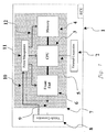
- the fuzzy-logic on-board device for monitoring and processing motor vehicle operating data comprises an on-board network connector 8, a front-end device 6, a CPU 3, an integrated store 4, a power management system 11, and a peripheral device interface connector 2.
- the CPU 3 is preferably a microchip, PIC16F877P model, microcontroller, operating to adjust and control the data flow and store related control data in store means of the device according to the present invention as well as process the acquired data flow analysis algorithms.
- the integrated store 4 preferably comprises a commercially available RAM store, of a 64 Kbyte static type, including buffer or backup battery means.
- the front end device 6 comprises preferably BJT transistors, of a NPN type, indicated by Q1, Q2, Q3, and at least a MOS transistor, and is designed to match the electric level characteristics of the motor vehicle on-board networks the device according to the invention is coupled to, which networks can be of a CAN, TTP, or a direct connection type, for example a K-line.
- the power management system 11 preferably comprises an integrated stabilizer power regulating device of a 7805 type, which is power supplied through the on-board network connector 8 and the inlet line 10, directly from the vehicle power supply circuit and operates to provide the front-end device 6, CPU 3 and store 4, with a regulated or stabilized 5-volt power supply, through the power supply lines 12.
- the CPU 3 is connected through a bus 13 to the front end device 6 and, through a further bus 14, to the store 4, said bus 14 comprising a 8-bit data bus, a 4-bit control bus, and an at least a 16-bit address bus.
- the front-end device, CPU 3, integrated store 4, power supply lines 10 and 12 and buses 13 and 14 are assembled on a single control card 7, of a printed circuit type to which said connector 8 is coupled through the lines 9 and 10, and said interface connector 2 is coupled through the coupling line 5.
- this very simple circuit together with the small capability store means necessary for processing data can be easily implemented in fully integrated form, thereby greatly reducing the size of the inventive device, which can be integrated on a single chip, and directly assembled in a conventional ECU, designed for motor vehicle use.
- Such an integrated on-board device can process operating data by a novel process, to be disclosed hereinafter, thereby also improving the control method of the motor vehicle single sub-systems.
- control method for processing information from the shared network (CAN or TTP network) or from the direct connection (K line) is shown in figure 2, and is related to an information field which can be considered as included in an artificial intelligence field pattern, in particular of a so-called “genetic algorithm construction", similar to a method for generating and selecting solutions in animal or vegetable species.
- the inventive method comprises two reiterating cycles, one nested into the other.
- the inner cycle of said cycles provides DNA genes, whereas the outer cycle selects said genes according to a fuzzy logic, collects two of the most similar DNA's, updates them and stores the method results.
- a DNA essentially represents a parameter matrix and a synthetic frame, defining a user type or a motor vehicle use type condition.
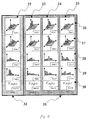
- Figure 3 shows a possible procedure of mapping the store means to store therein said genes and their DNA combinations.
- the columns indicated by the reference numbers 22, 23, 24, 25 represent store portions allocated for the DNA's.
- the shown DNA's are all defined by eight genes.
- the definition of a DNA is characterized by the structure thereof, and not by its contents.
- the rows indicated by the reference numbers 26 and 27 comprise discrete DNA genes and represent multidimensional statistic parameters, for example clustered distributions.
- the rows 28 and 29 comprise simple unidimensional distributing gene examples, whereas the row 30 comprises parametric genes, such as average values or standard offsets thereof.
- Each DNA is constituted in the gene generating step, i.e. in performing the innermost reiterating cycle of the method, for evaluating data based on statistic parameters to be formed.
- An essential parameter of this dynamically patterned method step is the condition to be applied for exiting the inner reiterating cycle, i.e. the so-called end-off-cycle condition, which sets that particular situation for which the DNA can be considered as fully formed.
- a gene can be represented by a clustered speed and acceleration distribution, and the end of cycle condition could be the joined condition of zero speed and low temperature of the engine.
- the genes are started to be filtered, according to selective criteria set by a fuzzy inference system, to clean the gene "image" from the zero-interest regions.
- fuzzy logic derives from the requirement of filtering genes in a quick, direct and flexible manner, to determine a continuous weight function in the measured data domain, or in a data linear combination domain, without performing transforms.
- the invention allows us to remain in the data domain, it is advantageously possible to perform a clean windowing of genes, to prevent non interesting domain regions for negatively affecting the DNA's processing verification steps.
- Figure 9 shows a conceptual diagram of the application of the fuzzy-logic filter, in which, as a gene, a clustered motor vehicle speed-acceleration distribution has been selected.
- the filter function structure is derived from the obtained weight function will be a normalized function, the value of which would be always included between 0 and 1, since it is a speed and acceleration function.
- the data processing method Upon detecting the most-similar DNA's, the data processing method will cluster them by generating a new DNA, as obtained for a weight combination of the two most similar DNA's.
- the statistic parameters associated with the new DNA are updated, by clustering weight and dispersion values of the DNA's which have generated them.
- the device according to the present invention will also save information related to the DNA weight, and dispersion and sequence thereof, i.e. the changing DNA sequence in the monitoring period.
- the device 1 continuously provides a processing weight for a new operating cycle to form a new evolving DNA pattern.
- figure 4 shows a typical architecture of the on-board electronic systems, in which the ECU's 33, 34, 36, 38 are coupled to one another through the shared network 35 or direct connections 37.
- the device 1 of the invention can be coupled in a fixed manner, as shown in figure 5, to become an integrating portion of the on-board electronic system and operate as an analyzer of the motor vehicle mode of use, to either provide the performed analyses to the other ECU's 33, 34, 36, 38 to take required strategic decisions, or it can store the analysis results in its store means for performing yet other subsequent analyses.
- the device 1 can be interfaced, while preserving the same capabilities, with sensors and actuators in replacement of any desired dedicated ECU's of a motor vehicle specific subsystem, while providing useful parameters for identifying the motor vehicle modes of operation, to further enhance the parameters the conventional control procedures are based upon.
- the device can be used for improving an ABS arrangement operation, by adding to its standard parameter set the motor vehicle tire wearing condition.
- the device can also be applied to change the motor vehicle engine control procedures based on the use driver of the engine to minimize the fuel consume and pollution, or provide information related to the wear condition of mechanical members or engine lubricating oil.
- the connector 2 provides connection with optional peripheral devices, for example an outer auxiliary processing unit 68 for sharing and plotting data, such as a personal computer or a palmar device, or, as shown in figure 7, a radio transmitter 60 or a wireless unit including an antenna 59 or an Ethernet adapter 65 for LAN networks, or other similar devices, of a stand-alone pattern, or associated with dedicated nets.
- peripheral devices for example an outer auxiliary processing unit 68 for sharing and plotting data, such as a personal computer or a palmar device, or, as shown in figure 7, a radio transmitter 60 or a wireless unit including an antenna 59 or an Ethernet adapter 65 for LAN networks, or other similar devices, of a stand-alone pattern, or associated with dedicated nets.
- the used materials, as well as the contingent size and shapes can be any, depending on requirements.
Abstract
Description
- The present invention relates to an electronic built-in on -board device, of a fuzzy-logic type, which has been specifically designed for monitoring, storing, processing and clustering data related to the operation of motor vehicles said device is applied to.
- The involved data can comprise parameters related to the operation of the motor vehicle in general, or an operating sub-system thereof.
- As is known, a very important requirement to be met in the motor vehicle and/or maintenance field, is that of providing on-board systems, specifically designed for collecting and processing data related to the operation of the motor vehicle, to optimize the system size and specifications of the single components of the motor vehicle and monitor their operation depending on their actual use.
- Prior technologic solutions to meet the above mentioned requirements, provide a low processing capability, require a lot of preset parameters and dedicated sensors, to be properly installed on the motor vehicle.
- Said prior systems are moreover affected by further drawbacks: for example they continuously record operating additional data, to provide redundant data packets, or preset sampling frequencies and times, which are fixed and/or limited by the store size requirements, thereby cannot be considered as fully autonomous, since a continuous monitoring through the overall operation time, or an implementation of dedicated or specifically designed sensors on the motor vehicle are required.
- Moreover, a specifically designed connecting system is also required, thereby the motor vehicle on-board electric system must be properly modified to derive therefrom the power supply for the measurement and sensor system.
- The above negatively affects the reliability of the motor vehicle and monitoring system thereof.
- A further drawback to be also considered is the high cost of the storing system, sensors, managing medium and control units.
- Accordingly, the aim of the present invention is to provide such an electronic device adapted to overcome the above mentioned problems, i.e. to properly record and process operating data of the motor vehicle the device is installed on, and cooperate, in a fully compatible manner, with on-board networks and systems, as well as properly poll electronic dedicated control units (ECU's) controlling motor vehicles.
- The above mentioned aim is achieved by an electronic microprocessor control unit, and a related software procedure, providing, based on fuzzy-logic principles, a full analysis of said operating data for deriving therefrom statistic index arrangements, thereby providing a control unit having a fully autonomous operating data managing capability.
- Such an inventive control unit or device, in particular, can be integrated on the on-board ECU's, so as to process data of said ECU's and provide said ECU's, in an interactive manner, with control data flows.
- Thus, the invention provides a lot of useful applications, such as:
- an identification of the user type, to optimize the designing of the motor vehicle and sub-systems thereof; a monitoring of the ageing status of the motor vehicle components, such as: tires, dampers, lubricating oil; an optimization of the motor vehicle use (which would be very useful for motor vehicle like that which could be performed by a fleet control applications) to provide information about the motor vehicle wear conditions useful on used motor vehicle market; a possibility of easily performing any derived risk analysis to be used by insurance companies for optimizing the cost rate and providing rate savings; and a recording of data related to the last operation of the motor vehicle, to provide diagnostic functions and the like.
-
- Within the scope of the above mentioned aim, a further object of the present invention is to derive in real time data related to the motor vehicle use mode from a plurality of on-board sensors coupled to respective dedicated electronic control units or ECU's, for providing integration and full compatibility with on-board networks, and achieving, from the thus processed data, a so-called "DNA", i.e. a statistic parameter array, providing a synthetic operation frame characterizing the use pattern of the motor vehicle.
- Yet another object of the present invention is to statistically process, in a fully autonomous manner, all the operation data and to return to the on-board ECU's further operating data related to motor vehicle sub-system operation.
- Yet another object of the present invention is to provide such a device which is very reliable and safe in operation.
- Yet another object of the present invention is to provide such a device which is very advantageous from a mere economic standpoint.
- According to one aspect of the present invention, the above mentioned aim and objects, as well as yet other objects, which will become more apparent hereinafter, are achieved by a fuzzy-logic on-board device for monitoring and processing motor vehicle operating data according to the accompanying claims.
- Further characteristics and advantages of the present invention will become more apparent hereinafter, from the following detailed disclosure of a preferred, though not exclusive, embodiment thereof, which is illustrated, by way of an indicative, but not limitative, example, in the accompanying drawings, where:
- Figure 1 is a constructional and functional block diagram of the device according to the present invention;
- Figure 2 illustrates a flow-chart related to the software algorithm implemented in fuzzy logic;
- Figure 3 illustrates a possible diagram of using store means included in the device according to the present invention;
- Figure 4 illustrates a device according to the invention applied outside of a motor vehicle;
- Figure 5 illustrates a device according to the present invention applied inside or on-board of the motor vehicle;
- Figure 6 illustrates a possible application of the device according to the present invention in replacement of an ECU;
- Figure 7 illustrates a circuit diagram for coupling the device according to the present invention to further auxiliary devices;
- Figure 8 illustrates an electric circuit used in the device according to the present invention: and
- Figure 9 illustrates a principle diagram of a fuzzy filter as implemented by the subject operating algorithm.
-
- With reference to the number references of the above mentioned figures, the fuzzy-logic on-board device for monitoring and processing motor vehicle operating data, according to the present invention, and which is generally indicated by the
reference number 1, comprises an on-board network connector 8, a front-end device 6, aCPU 3, an integratedstore 4, apower management system 11, and a peripheraldevice interface connector 2. - The
CPU 3 is preferably a microchip, PIC16F877P model, microcontroller, operating to adjust and control the data flow and store related control data in store means of the device according to the present invention as well as process the acquired data flow analysis algorithms. - The integrated
store 4 preferably comprises a commercially available RAM store, of a 64 Kbyte static type, including buffer or backup battery means. - The
front end device 6 comprises preferably BJT transistors, of a NPN type, indicated by Q1, Q2, Q3, and at least a MOS transistor, and is designed to match the electric level characteristics of the motor vehicle on-board networks the device according to the invention is coupled to, which networks can be of a CAN, TTP, or a direct connection type, for example a K-line. - The
power management system 11 preferably comprises an integrated stabilizer power regulating device of a 7805 type, which is power supplied through the on-board network connector 8 and theinlet line 10, directly from the vehicle power supply circuit and operates to provide the front-end device 6,CPU 3 andstore 4, with a regulated or stabilized 5-volt power supply, through thepower supply lines 12. - As shown the
CPU 3 is connected through abus 13 to thefront end device 6 and, through afurther bus 14, to thestore 4, saidbus 14 comprising a 8-bit data bus, a 4-bit control bus, and an at least a 16-bit address bus. - The front-end device,
CPU 3, integratedstore 4,power supply lines buses single control card 7, of a printed circuit type to which saidconnector 8 is coupled through thelines interface connector 2 is coupled through thecoupling line 5. - Thus, this very simple circuit together with the small capability store means necessary for processing data can be easily implemented in fully integrated form, thereby greatly reducing the size of the inventive device, which can be integrated on a single chip, and directly assembled in a conventional ECU, designed for motor vehicle use.
- Thus, such an integrated on-board device can process operating data by a novel process, to be disclosed hereinafter, thereby also improving the control method of the motor vehicle single sub-systems.
- The control method for processing information from the shared network (CAN or TTP network) or from the direct connection (K line) is shown in figure 2, and is related to an information field which can be considered as included in an artificial intelligence field pattern, in particular of a so-called "genetic algorithm construction", similar to a method for generating and selecting solutions in animal or vegetable species.
- More specifically, the inventive method comprises two reiterating cycles, one nested into the other.
- The inner cycle of said cycles provides DNA genes, whereas the outer cycle selects said genes according to a fuzzy logic, collects two of the most similar DNA's, updates them and stores the method results.
- In our application field, said genes represent statistic parameters, whereas a DNA essentially represents a parameter matrix and a synthetic frame, defining a user type or a motor vehicle use type condition.
- Figure 3 shows a possible procedure of mapping the store means to store therein said genes and their DNA combinations.
- The columns indicated by the
reference numbers - The shown DNA's are all defined by eight genes.
- The definition of a DNA is characterized by the structure thereof, and not by its contents.
- The rows indicated by the
reference numbers - The
rows row 30 comprises parametric genes, such as average values or standard offsets thereof. - Each DNA is constituted in the gene generating step, i.e. in performing the innermost reiterating cycle of the method, for evaluating data based on statistic parameters to be formed.
- An essential parameter of this dynamically patterned method step is the condition to be applied for exiting the inner reiterating cycle, i.e. the so-called end-off-cycle condition, which sets that particular situation for which the DNA can be considered as fully formed.
- For example, if it is necessary to typicize the motor vehicle kinematic use, then a gene can be represented by a clustered speed and acceleration distribution, and the end of cycle condition could be the joined condition of zero speed and low temperature of the engine.
- As the innermost reiterating cycle arrives at an end of cycle condition, the genes are started to be filtered, according to selective criteria set by a fuzzy inference system, to clean the gene "image" from the zero-interest regions.
- Then, a further analysis is performed to perform a data clustering operating step.
- This means that, as indicated by the
reference number 32, a novel DNA is formed and associated, as an additional information, with the DNA's in the remaining part of the store, i.e. thestore portion 31. - The herein provided use of a fuzzy logic derives from the requirement of filtering genes in a quick, direct and flexible manner, to determine a continuous weight function in the measured data domain, or in a data linear combination domain, without performing transforms.
- As is known, the calculation complexity greatly increases in calculating a transform operator, and an optional reverse transform operator, or anti-transformation operator, for performing domain changes.
- Thus, since the invention allows us to remain in the data domain, it is advantageously possible to perform a clean windowing of genes, to prevent non interesting domain regions for negatively affecting the DNA's processing verification steps.
- Figure 9 shows a conceptual diagram of the application of the fuzzy-logic filter, in which, as a gene, a clustered motor vehicle speed-acceleration distribution has been selected.
- For enhancing the region characterized by a zero acceleration it is sufficient to fuzzyfy the
respective speed 71,acceleration 72 andweight 74 function of therule assembly 73 defining the fuzzy inference the filter function structure is derived from the obtained weight function will be a normalized function, the value of which would be always included between 0 and 1, since it is a speed and acceleration function. - Upon detecting the most-similar DNA's, the data processing method will cluster them by generating a new DNA, as obtained for a weight combination of the two most similar DNA's.
- Then the statistic parameters associated with the new DNA are updated, by clustering weight and dispersion values of the DNA's which have generated them.
- Thus the device according to the present invention will also save information related to the DNA weight, and dispersion and sequence thereof, i.e. the changing DNA sequence in the monitoring period.
- As a latter method step, the
device 1 continuously provides a processing weight for a new operating cycle to form a new evolving DNA pattern. - Considering that motor vehicle makers conventionally use a
connector 40, the so-called OHD or EOBD, or other like connector, for interfacing with the outside of the motor vehicle shared networks, and accessing the on-board electric system for communicating with an outer unit the diagnostic information through the shared networks or direct connections, figure 4 shows a typical architecture of the on-board electronic systems, in which the ECU's 33, 34, 36, 38 are coupled to one another through the sharednetwork 35 ordirect connections 37. - The
device 1 of the invention can be coupled in a fixed manner, as shown in figure 5, to become an integrating portion of the on-board electronic system and operate as an analyzer of the motor vehicle mode of use, to either provide the performed analyses to the other ECU's 33, 34, 36, 38 to take required strategic decisions, or it can store the analysis results in its store means for performing yet other subsequent analyses. - Alternatively, as is shown in figure 1, the
device 1 can be interfaced, while preserving the same capabilities, with sensors and actuators in replacement of any desired dedicated ECU's of a motor vehicle specific subsystem, while providing useful parameters for identifying the motor vehicle modes of operation, to further enhance the parameters the conventional control procedures are based upon. - For example, the device can be used for improving an ABS arrangement operation, by adding to its standard parameter set the motor vehicle tire wearing condition.
- Moreover, the device can also be applied to change the motor vehicle engine control procedures based on the use driver of the engine to minimize the fuel consume and pollution, or provide information related to the wear condition of mechanical members or engine lubricating oil.
- As stated the
connector 2 provides connection with optional peripheral devices, for example an outerauxiliary processing unit 68 for sharing and plotting data, such as a personal computer or a palmar device, or, as shown in figure 7, aradio transmitter 60 or a wireless unit including anantenna 59 or anEthernet adapter 65 for LAN networks, or other similar devices, of a stand-alone pattern, or associated with dedicated nets. - From the above disclosure it should be apparent that the invention fully achieves the intended objects.
- The invention, as disclosed, is susceptible to several modifications and variations, all coming within the scope of the inventive idea.
- Moreover, all the constructional details can be replaced, the circuitry architectures included, by technically equivalent elements.
- In practicing the invention, the used materials, as well as the contingent size and shapes, can be any, depending on requirements.
Claims (19)
- An on-board electronic device, of a stand-alone and fuzzy-logic type, for monitoring and processing data related to a use of motor vehicles, characterized in that said device comprises an on-board network connector (8), a front-end device (6), a CPU (3), integrated store means (4), a power management system (11) and a peripheral device interface connector (2).
- An electronic on-board device, according to the preceding claim, characterized in that said CPU (3) is a microchip microcontroller, of a PIC16F877P type.
- An electronic on-board device, according to Claim 1, characterized in that said integrated store means comprise a 64 Kbyte static RAM memory, provided with a buffer or auxiliary store.
- An electronic on-board device, according to Claim 1, characterized in that said front-end device (6) comprises BJT transistors and/or a MOS transistor, to connect said device, through an on-board network connector (8) to a motor vehicle inner network such as: CAN, TTP or direct connections on a K-line.
- An electronic on-board device, according to Claim 1, characterized in that said power management system (11) comprises an integrated 7805 stabilizer device, power supplied through said connector (8) and an inlet line (10) directly from a motor vehicle power supply circuit providing said front-end device (6), CPU (3) and integrated store means (4) with a 5 volt regulated power supply, through power supply lines (12).
- An electronic on-board device, according to Claim 1, characterized in that said CPU (3) is connected, through a bus (13), to said front-end device (6) and, through a further bus (14), to said integrated store means (4).
- An electronic on-board device, according to Claim 1, characterized in that said front-end device (6), CPU (3), integrated store means (4), power supply lines (10, 12) and buses (13 and 14) are assembled on a single printed circuit board card (7).
- An electronic on-board device, according to Claim 1, characterized in that said device is connected, through said on-board network connector (8), to said motor vehicle inner networks therefrom said device receives data which are processed, in real time, by said CPU (3) according to an algorithm using fuzzy logic filter functions and clustering - storing data in gene and DNA forms and determining an automatic identification of a use mode of said motor vehicle.
- An electronic on-board device, according to Claim 1, characterized in that said integrated store means (4) are mapped into genes (26-30) and DNA's (22-25) and store multidimensional, unidimensional statistic parameters or simple values.
- An electronic on-board device, according to Claim 1, characterized in that said device, for processing said data, provides a generation and evolvement of said genes and an unification of said DNA's through artificial intelligence algorithmic instruments.
- An electronic on-board device, according to Claim 10, characterized in that an algorithm used for processing said data implements at least two reiterative nested cycles, i.e. an inner cycle for providing said genes and building said DNA's, and a selection outer cycle based on a fuzzy logic of said genes, and performing an unification of two most similar DNA's of said DNA's in a store portion (31) of said store means (4), updating said DNA's and storing (32) of a result of said DNA processing.
- An electronic on-board device, according to Claim 1, characterized in that said fuzzy logic provides to filter said genes in a direct manner in a domain of measured data, by fuzzyfying said genes (71, 72) and a weight function (74) by fuzzy rules (73) for deriving normalized filter functions and starting gene functions.
- An electronic on-board device, according to Claim 1, characterized in that said device is coupled, through said on-board network connector (8), to a connector (40) of an OBD or EOBD type, for interfacing the motor vehicle inner networks with an outside of said motor vehicle.
- An electronic on-board device, according to Claim 1, characterized in that said device is fixedly applied in said motor vehicle by fully integrating said device in an on-board electronic system, including ECU's (33, 24, 36, 38) coupled to one another through a shared network (35) or direct connections (37).
- An electronic on-board device, according to Claim 1, characterized in that said device is directly interfaced with sensors and actuators, to provide enhanced operating parameters including statistic parameters defining use procedures of motor vehicle sub-systems.
- An electronic on-board device, according to Claim 1, characterized in that said interface connector (2) provides connections with optional peripheral devices, such as an outer auxiliary processing unit (68), radio transmitters or wireless devices (60) including an antenna (59) or an Ethernet adapter (65) for LAN networks.
- An electronic on-board device, according to Claim 1, characterized in that said interface connector (2) is coupled to said printed board circuit card through said coupling line (5).
- An electronic on-board device, according to Claim 1, characterized in that said on-board network connector (8) is coupled to said printed board circuit card (7) through said coupling lines (9, 10).
- An electronic on-board device, according to Claim 1, characterized in that said device is made in integrated technology and mounted on-board of said motor vehicle.
Applications Claiming Priority (2)
| Application Number | Priority Date | Filing Date | Title |
|---|---|---|---|
| IT2001MI001283A ITMI20011283A1 (en) | 2001-06-18 | 2001-06-18 | AUTONOMOUS ELECTRONIC ON-BOARD DEVICE WITH FUZZY LOGIC PARTICULARLY DESIGNED TO MONITOR AND PROCESS DATA RELATING TO THE USE OF THE AU |
| ITMI20011283 | 2001-06-18 |
Publications (3)
| Publication Number | Publication Date |
|---|---|
| EP1270914A2 true EP1270914A2 (en) | 2003-01-02 |
| EP1270914A3 EP1270914A3 (en) | 2004-10-06 |
| EP1270914B1 EP1270914B1 (en) | 2011-03-16 |
Family
ID=11447890
Family Applications (1)
| Application Number | Title | Priority Date | Filing Date |
|---|---|---|---|
| EP02013066A Expired - Lifetime EP1270914B1 (en) | 2001-06-18 | 2002-06-13 | Electronic device for monitoring and processing motor vehicle operating data |
Country Status (5)
| Country | Link |
|---|---|
| US (1) | US7146346B2 (en) |
| EP (1) | EP1270914B1 (en) |
| AT (1) | ATE502199T1 (en) |
| DE (1) | DE60239436D1 (en) |
| IT (1) | ITMI20011283A1 (en) |
Families Citing this family (6)
| Publication number | Priority date | Publication date | Assignee | Title |
|---|---|---|---|---|
| US8140358B1 (en) | 1996-01-29 | 2012-03-20 | Progressive Casualty Insurance Company | Vehicle monitoring system |
| US8090598B2 (en) * | 1996-01-29 | 2012-01-03 | Progressive Casualty Insurance Company | Monitoring system for determining and communicating a cost of insurance |
| US9916625B2 (en) | 2012-02-02 | 2018-03-13 | Progressive Casualty Insurance Company | Mobile insurance platform system |
| US10109014B1 (en) | 2013-03-15 | 2018-10-23 | Allstate Insurance Company | Pre-calculated insurance premiums with wildcarding |
| US10747228B2 (en) * | 2017-07-03 | 2020-08-18 | Baidu Usa Llc | Centralized scheduling system for operating autonomous driving vehicles |
| DE102021203345B3 (en) | 2021-04-01 | 2022-10-06 | Volkswagen Aktiengesellschaft | Vehicle with a DNA memory |
Family Cites Families (6)
| Publication number | Priority date | Publication date | Assignee | Title |
|---|---|---|---|---|
| US5414645A (en) * | 1991-10-25 | 1995-05-09 | Mazda Motor Corporation | Method of fault diagnosis in an apparatus having sensors |
| US5983161A (en) * | 1993-08-11 | 1999-11-09 | Lemelson; Jerome H. | GPS vehicle collision avoidance warning and control system and method |
| US5570087A (en) * | 1994-02-18 | 1996-10-29 | Lemelson; Jerome H. | Motor vehicle performance monitor and method |
| US5499182A (en) * | 1994-12-07 | 1996-03-12 | Ousborne; Jeffrey | Vehicle driver performance monitoring system |
| DE19709445B4 (en) * | 1997-03-07 | 2004-01-15 | Volkswagen Ag | Device and method for calculating and displaying service intervals |
| WO2000060547A1 (en) * | 1999-03-31 | 2000-10-12 | Robert Bosch Gmbh | Method and device for storing data in a vehicle and for evaluating said stored data |
-
2001
- 2001-06-18 IT IT2001MI001283A patent/ITMI20011283A1/en unknown
-
2002
- 2002-06-13 EP EP02013066A patent/EP1270914B1/en not_active Expired - Lifetime
- 2002-06-13 DE DE60239436T patent/DE60239436D1/en not_active Expired - Lifetime
- 2002-06-13 AT AT02013066T patent/ATE502199T1/en not_active IP Right Cessation
- 2002-06-14 US US10/172,145 patent/US7146346B2/en not_active Expired - Lifetime
Non-Patent Citations (1)
| Title |
|---|
| None |
Also Published As
| Publication number | Publication date |
|---|---|
| EP1270914A3 (en) | 2004-10-06 |
| EP1270914B1 (en) | 2011-03-16 |
| ITMI20011283A1 (en) | 2002-12-18 |
| DE60239436D1 (en) | 2011-04-28 |
| ATE502199T1 (en) | 2011-04-15 |
| ITMI20011283A0 (en) | 2001-06-18 |
| US7146346B2 (en) | 2006-12-05 |
| US20030023568A1 (en) | 2003-01-30 |
Similar Documents
| Publication | Publication Date | Title |
|---|---|---|
| US8543282B2 (en) | Remote diagnosis modelling | |
| US6819986B2 (en) | System and method for collecting vehicle data and diagnosing the vehicle, and method for automatically setting the vehicle convenience apparatus using smartcard | |
| EP2112492B1 (en) | Test requirement list for diagnostic tests | |
| US8285441B2 (en) | User configurable scan tool | |
| US20060052919A1 (en) | System for collecting vehicle data and diagnosticating the vehicle using USB hard drive | |
| US20060229777A1 (en) | System and methods of performing real-time on-board automotive telemetry analysis and reporting | |
| US9928669B2 (en) | System and method for providing optimal state indication of a vehicle | |
| US20160110935A1 (en) | Fuel Savings Scoring System With Remote Real-Time Vehicle OBD Monitoring | |
| US7146346B2 (en) | Fuzzy-logic on board device for monitoring and processing motor vehicle operating data | |
| US20180130267A1 (en) | Onboard diagnostic system and method | |
| KR100400945B1 (en) | System and method for collecting vehicle data and diagnosticating the vehicle, and method for automatically setting the vehicle convenience apparatus using smartcard | |
| US20220180671A1 (en) | Methods and systems for engine diagnostics for vehicles using obd port | |
| EP4033413A1 (en) | Artificial neural network training method for predicting whether vehicle is in trouble, method for determining whether vehicle is in trouble, and computing system performing same | |
| US9679422B2 (en) | Method for increasing accuracy of vehicle data | |
| CN115237686A (en) | Method and device for detecting abnormal function of vehicle-mounted embedded computer | |
| EP3613975B1 (en) | Method and system for determining a cause of extra-fuel consumption | |
| US20230131925A1 (en) | Methods and systems of an online vehicle sale website | |
| Singh et al. | OBD II-Based Performance Analysis Based on Fuel Usage of Vehicles | |
| Dabell et al. | Inferential sensing techniques to enable condition based maintenance | |
| CN117422294A (en) | Method, device, equipment and storage medium for determining power deficiency factor | |
| JP2021081958A (en) | Vehicle management device and communication management method | |
| CN107831695A (en) | A kind of vehicle-mounted data excavation control apparatus | |
| Sawant et al. | A Mobile Application for Monitoring Inefficient &Unsafe Driving Behavior |
Legal Events
| Date | Code | Title | Description |
|---|---|---|---|
| PUAI | Public reference made under article 153(3) epc to a published international application that has entered the european phase |
Free format text: ORIGINAL CODE: 0009012 |
|
| AK | Designated contracting states |
Kind code of ref document: A2 Designated state(s): AT BE CH CY DE DK ES FI FR GB GR IE IT LI LU MC NL PT SE TR |
|
| AX | Request for extension of the european patent |
Free format text: AL;LT;LV;MK;RO;SI |
|
| PUAL | Search report despatched |
Free format text: ORIGINAL CODE: 0009013 |
|
| AK | Designated contracting states |
Kind code of ref document: A3 Designated state(s): AT BE CH CY DE DK ES FI FR GB GR IE IT LI LU MC NL PT SE TR |
|
| AX | Request for extension of the european patent |
Extension state: AL LT LV MK RO SI |
|
| 17P | Request for examination filed |
Effective date: 20041210 |
|
| AKX | Designation fees paid |
Designated state(s): AT BE CH CY DE DK ES FI FR GB GR IE IT LI LU MC NL PT SE TR |
|
| GRAP | Despatch of communication of intention to grant a patent |
Free format text: ORIGINAL CODE: EPIDOSNIGR1 |
|
| RTI1 | Title (correction) |
Free format text: ELECTRONIC DEVICE FOR MONITORING AND PROCESSING MOTOR VEHICLE OPERATING DATA |
|
| GRAS | Grant fee paid |
Free format text: ORIGINAL CODE: EPIDOSNIGR3 |
|
| GRAA | (expected) grant |
Free format text: ORIGINAL CODE: 0009210 |
|
| AK | Designated contracting states |
Kind code of ref document: B1 Designated state(s): AT BE CH CY DE DK ES FI FR GB GR IE IT LI LU MC NL PT SE TR |
|
| REG | Reference to a national code |
Ref country code: GB Ref legal event code: FG4D |
|
| REG | Reference to a national code |
Ref country code: CH Ref legal event code: EP |
|
| REG | Reference to a national code |
Ref country code: IE Ref legal event code: FG4D |
|
| REF | Corresponds to: |
Ref document number: 60239436 Country of ref document: DE Date of ref document: 20110428 Kind code of ref document: P |
|
| REG | Reference to a national code |
Ref country code: DE Ref legal event code: R096 Ref document number: 60239436 Country of ref document: DE Effective date: 20110428 |
|
| REG | Reference to a national code |
Ref country code: NL Ref legal event code: VDEP Effective date: 20110316 |
|
| PG25 | Lapsed in a contracting state [announced via postgrant information from national office to epo] |
Ref country code: ES Free format text: LAPSE BECAUSE OF FAILURE TO SUBMIT A TRANSLATION OF THE DESCRIPTION OR TO PAY THE FEE WITHIN THE PRESCRIBED TIME-LIMIT Effective date: 20110627 Ref country code: GR Free format text: LAPSE BECAUSE OF FAILURE TO SUBMIT A TRANSLATION OF THE DESCRIPTION OR TO PAY THE FEE WITHIN THE PRESCRIBED TIME-LIMIT Effective date: 20110617 Ref country code: SE Free format text: LAPSE BECAUSE OF FAILURE TO SUBMIT A TRANSLATION OF THE DESCRIPTION OR TO PAY THE FEE WITHIN THE PRESCRIBED TIME-LIMIT Effective date: 20110316 |
|
| PG25 | Lapsed in a contracting state [announced via postgrant information from national office to epo] |
Ref country code: CY Free format text: LAPSE BECAUSE OF FAILURE TO SUBMIT A TRANSLATION OF THE DESCRIPTION OR TO PAY THE FEE WITHIN THE PRESCRIBED TIME-LIMIT Effective date: 20110316 Ref country code: AT Free format text: LAPSE BECAUSE OF FAILURE TO SUBMIT A TRANSLATION OF THE DESCRIPTION OR TO PAY THE FEE WITHIN THE PRESCRIBED TIME-LIMIT Effective date: 20110316 Ref country code: FI Free format text: LAPSE BECAUSE OF FAILURE TO SUBMIT A TRANSLATION OF THE DESCRIPTION OR TO PAY THE FEE WITHIN THE PRESCRIBED TIME-LIMIT Effective date: 20110316 |
|
| PG25 | Lapsed in a contracting state [announced via postgrant information from national office to epo] |
Ref country code: BE Free format text: LAPSE BECAUSE OF FAILURE TO SUBMIT A TRANSLATION OF THE DESCRIPTION OR TO PAY THE FEE WITHIN THE PRESCRIBED TIME-LIMIT Effective date: 20110316 |
|
| PG25 | Lapsed in a contracting state [announced via postgrant information from national office to epo] |
Ref country code: PT Free format text: LAPSE BECAUSE OF FAILURE TO SUBMIT A TRANSLATION OF THE DESCRIPTION OR TO PAY THE FEE WITHIN THE PRESCRIBED TIME-LIMIT Effective date: 20110718 |
|
| PG25 | Lapsed in a contracting state [announced via postgrant information from national office to epo] |
Ref country code: NL Free format text: LAPSE BECAUSE OF FAILURE TO SUBMIT A TRANSLATION OF THE DESCRIPTION OR TO PAY THE FEE WITHIN THE PRESCRIBED TIME-LIMIT Effective date: 20110316 |
|
| PLBE | No opposition filed within time limit |
Free format text: ORIGINAL CODE: 0009261 |
|
| STAA | Information on the status of an ep patent application or granted ep patent |
Free format text: STATUS: NO OPPOSITION FILED WITHIN TIME LIMIT |
|
| REG | Reference to a national code |
Ref country code: CH Ref legal event code: PL |
|
| 26N | No opposition filed |
Effective date: 20111219 |
|
| PG25 | Lapsed in a contracting state [announced via postgrant information from national office to epo] |
Ref country code: DK Free format text: LAPSE BECAUSE OF FAILURE TO SUBMIT A TRANSLATION OF THE DESCRIPTION OR TO PAY THE FEE WITHIN THE PRESCRIBED TIME-LIMIT Effective date: 20110316 |
|
| REG | Reference to a national code |
Ref country code: IE Ref legal event code: MM4A |
|
| REG | Reference to a national code |
Ref country code: DE Ref legal event code: R097 Ref document number: 60239436 Country of ref document: DE Effective date: 20111219 |
|
| PG25 | Lapsed in a contracting state [announced via postgrant information from national office to epo] |
Ref country code: CH Free format text: LAPSE BECAUSE OF NON-PAYMENT OF DUE FEES Effective date: 20110630 Ref country code: IE Free format text: LAPSE BECAUSE OF NON-PAYMENT OF DUE FEES Effective date: 20110613 Ref country code: LI Free format text: LAPSE BECAUSE OF NON-PAYMENT OF DUE FEES Effective date: 20110630 |
|
| PG25 | Lapsed in a contracting state [announced via postgrant information from national office to epo] |
Ref country code: MC Free format text: LAPSE BECAUSE OF NON-PAYMENT OF DUE FEES Effective date: 20110630 |
|
| PG25 | Lapsed in a contracting state [announced via postgrant information from national office to epo] |
Ref country code: LU Free format text: LAPSE BECAUSE OF NON-PAYMENT OF DUE FEES Effective date: 20110613 |
|
| PG25 | Lapsed in a contracting state [announced via postgrant information from national office to epo] |
Ref country code: TR Free format text: LAPSE BECAUSE OF FAILURE TO SUBMIT A TRANSLATION OF THE DESCRIPTION OR TO PAY THE FEE WITHIN THE PRESCRIBED TIME-LIMIT Effective date: 20110316 |
|
| REG | Reference to a national code |
Ref country code: FR Ref legal event code: PLFP Year of fee payment: 15 |
|
| REG | Reference to a national code |
Ref country code: FR Ref legal event code: PLFP Year of fee payment: 16 |
|
| REG | Reference to a national code |
Ref country code: FR Ref legal event code: PLFP Year of fee payment: 17 |
|
| PGFP | Annual fee paid to national office [announced via postgrant information from national office to epo] |
Ref country code: DE Payment date: 20210630 Year of fee payment: 20 |
|
| PGFP | Annual fee paid to national office [announced via postgrant information from national office to epo] |
Ref country code: IT Payment date: 20210810 Year of fee payment: 20 Ref country code: FR Payment date: 20210809 Year of fee payment: 20 |
|
| PGFP | Annual fee paid to national office [announced via postgrant information from national office to epo] |
Ref country code: GB Payment date: 20210810 Year of fee payment: 20 |
|
| REG | Reference to a national code |
Ref country code: DE Ref legal event code: R071 Ref document number: 60239436 Country of ref document: DE |
|
| REG | Reference to a national code |
Ref country code: GB Ref legal event code: PE20 Expiry date: 20220612 |
|
| PG25 | Lapsed in a contracting state [announced via postgrant information from national office to epo] |
Ref country code: GB Free format text: LAPSE BECAUSE OF EXPIRATION OF PROTECTION Effective date: 20220612 |