EP1270073A1 - Mikrofluid-System mit Regler - Google Patents
Mikrofluid-System mit Regler Download PDFInfo
- Publication number
- EP1270073A1 EP1270073A1 EP01115587A EP01115587A EP1270073A1 EP 1270073 A1 EP1270073 A1 EP 1270073A1 EP 01115587 A EP01115587 A EP 01115587A EP 01115587 A EP01115587 A EP 01115587A EP 1270073 A1 EP1270073 A1 EP 1270073A1
- Authority
- EP
- European Patent Office
- Prior art keywords
- electrode
- channel
- channels
- fluid
- electrical
- Prior art date
- Legal status (The legal status is an assumption and is not a legal conclusion. Google has not performed a legal analysis and makes no representation as to the accuracy of the status listed.)
- Granted
Links
Images

Classifications
-
- B—PERFORMING OPERATIONS; TRANSPORTING
- B01—PHYSICAL OR CHEMICAL PROCESSES OR APPARATUS IN GENERAL
- B01L—CHEMICAL OR PHYSICAL LABORATORY APPARATUS FOR GENERAL USE
- B01L3/00—Containers or dishes for laboratory use, e.g. laboratory glassware; Droppers
- B01L3/50—Containers for the purpose of retaining a material to be analysed, e.g. test tubes
- B01L3/502—Containers for the purpose of retaining a material to be analysed, e.g. test tubes with fluid transport, e.g. in multi-compartment structures
- B01L3/5027—Containers for the purpose of retaining a material to be analysed, e.g. test tubes with fluid transport, e.g. in multi-compartment structures by integrated microfluidic structures, i.e. dimensions of channels and chambers are such that surface tension forces are important, e.g. lab-on-a-chip
- B01L3/50273—Containers for the purpose of retaining a material to be analysed, e.g. test tubes with fluid transport, e.g. in multi-compartment structures by integrated microfluidic structures, i.e. dimensions of channels and chambers are such that surface tension forces are important, e.g. lab-on-a-chip characterised by the means or forces applied to move the fluids
-
- B—PERFORMING OPERATIONS; TRANSPORTING
- B01—PHYSICAL OR CHEMICAL PROCESSES OR APPARATUS IN GENERAL
- B01L—CHEMICAL OR PHYSICAL LABORATORY APPARATUS FOR GENERAL USE
- B01L3/00—Containers or dishes for laboratory use, e.g. laboratory glassware; Droppers
- B01L3/50—Containers for the purpose of retaining a material to be analysed, e.g. test tubes
- B01L3/502—Containers for the purpose of retaining a material to be analysed, e.g. test tubes with fluid transport, e.g. in multi-compartment structures
- B01L3/5027—Containers for the purpose of retaining a material to be analysed, e.g. test tubes with fluid transport, e.g. in multi-compartment structures by integrated microfluidic structures, i.e. dimensions of channels and chambers are such that surface tension forces are important, e.g. lab-on-a-chip
- B01L3/502715—Containers for the purpose of retaining a material to be analysed, e.g. test tubes with fluid transport, e.g. in multi-compartment structures by integrated microfluidic structures, i.e. dimensions of channels and chambers are such that surface tension forces are important, e.g. lab-on-a-chip characterised by interfacing components, e.g. fluidic, electrical, optical or mechanical interfaces
-
- G—PHYSICS
- G01—MEASURING; TESTING
- G01N—INVESTIGATING OR ANALYSING MATERIALS BY DETERMINING THEIR CHEMICAL OR PHYSICAL PROPERTIES
- G01N27/00—Investigating or analysing materials by the use of electric, electrochemical, or magnetic means
- G01N27/26—Investigating or analysing materials by the use of electric, electrochemical, or magnetic means by investigating electrochemical variables; by using electrolysis or electrophoresis
- G01N27/416—Systems
- G01N27/447—Systems using electrophoresis
- G01N27/44704—Details; Accessories
- G01N27/44717—Arrangements for investigating the separated zones, e.g. localising zones
-
- G—PHYSICS
- G01—MEASURING; TESTING
- G01N—INVESTIGATING OR ANALYSING MATERIALS BY DETERMINING THEIR CHEMICAL OR PHYSICAL PROPERTIES
- G01N27/00—Investigating or analysing materials by the use of electric, electrochemical, or magnetic means
- G01N27/26—Investigating or analysing materials by the use of electric, electrochemical, or magnetic means by investigating electrochemical variables; by using electrolysis or electrophoresis
- G01N27/416—Systems
- G01N27/447—Systems using electrophoresis
- G01N27/44704—Details; Accessories
- G01N27/44752—Controlling the zeta potential, e.g. by wall coatings
-
- G—PHYSICS
- G01—MEASURING; TESTING
- G01N—INVESTIGATING OR ANALYSING MATERIALS BY DETERMINING THEIR CHEMICAL OR PHYSICAL PROPERTIES
- G01N27/00—Investigating or analysing materials by the use of electric, electrochemical, or magnetic means
- G01N27/26—Investigating or analysing materials by the use of electric, electrochemical, or magnetic means by investigating electrochemical variables; by using electrolysis or electrophoresis
- G01N27/416—Systems
- G01N27/447—Systems using electrophoresis
- G01N27/44756—Apparatus specially adapted therefor
- G01N27/44791—Microapparatus
-
- B—PERFORMING OPERATIONS; TRANSPORTING
- B01—PHYSICAL OR CHEMICAL PROCESSES OR APPARATUS IN GENERAL
- B01L—CHEMICAL OR PHYSICAL LABORATORY APPARATUS FOR GENERAL USE
- B01L2200/00—Solutions for specific problems relating to chemical or physical laboratory apparatus
- B01L2200/14—Process control and prevention of errors
- B01L2200/143—Quality control, feedback systems
-
- B—PERFORMING OPERATIONS; TRANSPORTING
- B01—PHYSICAL OR CHEMICAL PROCESSES OR APPARATUS IN GENERAL
- B01L—CHEMICAL OR PHYSICAL LABORATORY APPARATUS FOR GENERAL USE
- B01L2300/00—Additional constructional details
- B01L2300/06—Auxiliary integrated devices, integrated components
- B01L2300/0627—Sensor or part of a sensor is integrated
- B01L2300/0645—Electrodes
-
- B—PERFORMING OPERATIONS; TRANSPORTING
- B01—PHYSICAL OR CHEMICAL PROCESSES OR APPARATUS IN GENERAL
- B01L—CHEMICAL OR PHYSICAL LABORATORY APPARATUS FOR GENERAL USE
- B01L2300/00—Additional constructional details
- B01L2300/08—Geometry, shape and general structure
- B01L2300/0809—Geometry, shape and general structure rectangular shaped
- B01L2300/0816—Cards, e.g. flat sample carriers usually with flow in two horizontal directions
-
- B—PERFORMING OPERATIONS; TRANSPORTING
- B01—PHYSICAL OR CHEMICAL PROCESSES OR APPARATUS IN GENERAL
- B01L—CHEMICAL OR PHYSICAL LABORATORY APPARATUS FOR GENERAL USE
- B01L2300/00—Additional constructional details
- B01L2300/08—Geometry, shape and general structure
- B01L2300/0861—Configuration of multiple channels and/or chambers in a single devices
- B01L2300/0867—Multiple inlets and one sample wells, e.g. mixing, dilution
-
- B—PERFORMING OPERATIONS; TRANSPORTING
- B01—PHYSICAL OR CHEMICAL PROCESSES OR APPARATUS IN GENERAL
- B01L—CHEMICAL OR PHYSICAL LABORATORY APPARATUS FOR GENERAL USE
- B01L2400/00—Moving or stopping fluids
- B01L2400/04—Moving fluids with specific forces or mechanical means
- B01L2400/0403—Moving fluids with specific forces or mechanical means specific forces
- B01L2400/0415—Moving fluids with specific forces or mechanical means specific forces electrical forces, e.g. electrokinetic
-
- B—PERFORMING OPERATIONS; TRANSPORTING
- B01—PHYSICAL OR CHEMICAL PROCESSES OR APPARATUS IN GENERAL
- B01L—CHEMICAL OR PHYSICAL LABORATORY APPARATUS FOR GENERAL USE
- B01L2400/00—Moving or stopping fluids
- B01L2400/04—Moving fluids with specific forces or mechanical means
- B01L2400/0403—Moving fluids with specific forces or mechanical means specific forces
- B01L2400/043—Moving fluids with specific forces or mechanical means specific forces magnetic forces
-
- B—PERFORMING OPERATIONS; TRANSPORTING
- B01—PHYSICAL OR CHEMICAL PROCESSES OR APPARATUS IN GENERAL
- B01L—CHEMICAL OR PHYSICAL LABORATORY APPARATUS FOR GENERAL USE
- B01L2400/00—Moving or stopping fluids
- B01L2400/04—Moving fluids with specific forces or mechanical means
- B01L2400/0403—Moving fluids with specific forces or mechanical means specific forces
- B01L2400/0433—Moving fluids with specific forces or mechanical means specific forces vibrational forces
- B01L2400/0436—Moving fluids with specific forces or mechanical means specific forces vibrational forces acoustic forces, e.g. surface acoustic waves [SAW]
-
- B—PERFORMING OPERATIONS; TRANSPORTING
- B01—PHYSICAL OR CHEMICAL PROCESSES OR APPARATUS IN GENERAL
- B01L—CHEMICAL OR PHYSICAL LABORATORY APPARATUS FOR GENERAL USE
- B01L2400/00—Moving or stopping fluids
- B01L2400/04—Moving fluids with specific forces or mechanical means
- B01L2400/0475—Moving fluids with specific forces or mechanical means specific mechanical means and fluid pressure
- B01L2400/0487—Moving fluids with specific forces or mechanical means specific mechanical means and fluid pressure fluid pressure, pneumatics
-
- B—PERFORMING OPERATIONS; TRANSPORTING
- B01—PHYSICAL OR CHEMICAL PROCESSES OR APPARATUS IN GENERAL
- B01L—CHEMICAL OR PHYSICAL LABORATORY APPARATUS FOR GENERAL USE
- B01L3/00—Containers or dishes for laboratory use, e.g. laboratory glassware; Droppers
- B01L3/02—Burettes; Pipettes
- B01L3/0241—Drop counters; Drop formers
-
- Y—GENERAL TAGGING OF NEW TECHNOLOGICAL DEVELOPMENTS; GENERAL TAGGING OF CROSS-SECTIONAL TECHNOLOGIES SPANNING OVER SEVERAL SECTIONS OF THE IPC; TECHNICAL SUBJECTS COVERED BY FORMER USPC CROSS-REFERENCE ART COLLECTIONS [XRACs] AND DIGESTS
- Y10—TECHNICAL SUBJECTS COVERED BY FORMER USPC
- Y10T—TECHNICAL SUBJECTS COVERED BY FORMER US CLASSIFICATION
- Y10T137/00—Fluid handling
- Y10T137/0318—Processes
- Y10T137/0396—Involving pressure control
-
- Y—GENERAL TAGGING OF NEW TECHNOLOGICAL DEVELOPMENTS; GENERAL TAGGING OF CROSS-SECTIONAL TECHNOLOGIES SPANNING OVER SEVERAL SECTIONS OF THE IPC; TECHNICAL SUBJECTS COVERED BY FORMER USPC CROSS-REFERENCE ART COLLECTIONS [XRACs] AND DIGESTS
- Y10—TECHNICAL SUBJECTS COVERED BY FORMER USPC
- Y10T—TECHNICAL SUBJECTS COVERED BY FORMER US CLASSIFICATION
- Y10T137/00—Fluid handling
- Y10T137/206—Flow affected by fluid contact, energy field or coanda effect [e.g., pure fluid device or system]
- Y10T137/218—Means to regulate or vary operation of device
- Y10T137/2191—By non-fluid energy field affecting input [e.g., transducer]
- Y10T137/2196—Acoustical or thermal energy
-
- Y—GENERAL TAGGING OF NEW TECHNOLOGICAL DEVELOPMENTS; GENERAL TAGGING OF CROSS-SECTIONAL TECHNOLOGIES SPANNING OVER SEVERAL SECTIONS OF THE IPC; TECHNICAL SUBJECTS COVERED BY FORMER USPC CROSS-REFERENCE ART COLLECTIONS [XRACs] AND DIGESTS
- Y10—TECHNICAL SUBJECTS COVERED BY FORMER USPC
- Y10T—TECHNICAL SUBJECTS COVERED BY FORMER US CLASSIFICATION
- Y10T137/00—Fluid handling
- Y10T137/8158—With indicator, register, recorder, alarm or inspection means
- Y10T137/8326—Fluid pressure responsive indicator, recorder or alarm
Definitions
- the invention relates to a microfluid system, in particular a microfluid chip at least one working channel in which a fluid and / or contained therein Components by means of a driving force, in particular by using Pressure, acoustic energy, an electrical and / or a magnetic field are movable in the direction of the working channel and a method for transport and the guidance of a fluid and / or components contained therein, in one such microfluid system.
- Such a device and such a method are known from US 5,965,001, US 5,800,690 and from Electrophoresis (2000), pages 100-106 and pages 107 to 115 previously known.
- the content of these documents is attached to this Job fully included for any purpose, as in these Documents important features, especially regarding the constructive and material training of such microfluidic systems and possible ones Procedures for the transportation and management of fluids and / or contained therein Components in such microfluidic systems are disclosed, that is, features, for individually or in combination with each other, in combination with those in this Registration additional features disclosed protection is claimed.
- Such microfluidic systems are of particular interest for applications in Field of electroosmosis and / or electrophoresis, for reasons of Economy and a correspondingly larger range of applications preferred open network of fluid-connected miniature channels is used.
- These electrical parameters are usually introduced into the fluid by means of suitable electrodes respective ends of the partially intersecting channels with so-called reservoirs are contacted, which in turn are in fluid communication with the individual microchannels stand.
- Assay defined, i.e. for a given microfluidic system, preferably one Microfluidic chip, certain reagents and a certain data analysis and also a certain time sequence for the electrical parameters, in particular the electrical current and / or the electrical voltage certain temperatures for each electrode in a so-called table "Script" set.
- the user will eventually see a log of that Field of application of the respective microfluid system and its respective application limits informed.
- This protocol also defines the limits regarding the using substances or fluids and their concentrations. This Limits must also be due to the time invariant statically defined in the script Parameters are comparatively narrowly defined.
- the electrical Parameters especially the electrical currents and / or the electrical ones Voltages at the individual electrodes are graded in certain time periods changed, with special electrical circuits, such as current or voltage regulator Make sure that the respective electrical parameters are above the desired Period of time at the respective electrode can be kept constant.
- Microfluid system i.e. the more fluid-connected micro-channels are provided.
- the more fluid-connected micro-channels are provided.
- four channels which at one point form a cross-connection are fluid-connected and at the end each have a reservoir and an electrode are provided an independent increase in fluid flow between two Reservoirs not only by increasing the voltage difference across the achievable in both reservoirs.
- the tensions on the other two reservoirs must also be reset if the original flow and to keep its direction.
- usually different ones different electrical parameters simultaneously on several electrodes i.e. according to the respective script.
- microfluid systems are subject to this both internal and external disturbance variables, which the test result also because of the access to the others, if any Channels, can significantly influence.
- Such disturbances can, for example due to the manufacturing process due to slight dimensional deviations of the microfluid channels be conditional.
- the term "microfluid” refers to miniature channels that one Have cross-section in the order of 0.1 to 500 microns. typical Dimensions of such miniature channels are, for example, 15 ⁇ m deep and 40 ⁇ m width.
- the respective channel geometry essentially determines the effective one Resistance of a liquid, so that the flow and the electrical Characteristics when changing the channel geometry also corresponding change.
- the manufacturing tolerances for the manufacture of such miniature channels are however, there are limits for economic reasons.
- Electrodes are not directly in or on the Micro channels of the microfluid system can be used as it is connected to the Electrodes often leads to an undesirable gas bubble formation.
- gas bubbles can increase the miniaturized channels effective resistance up to an infinitely large effective resistance to lead.
- the electrodes are usually made with reservoirs connected, which can accommodate a comparatively large volume of fluid and the significantly larger dimensions compared to the geometry of the miniature channels exhibit.
- this means that the electrodes are inserted at the respective end of the Miniature channels limited.
- microfluid system and a method for transporting and guiding a fluid and / or components contained therein in such a microfluidic system that has a wider application and Range of use and a reduced sensitivity to internal and / or external disturbance variables and consequently greater operational reliability.
- the working channel opening measuring channel is fluidly connected, which is coupled to the sensor.
- suitable measuring and / or Intervention options for the introduction and / or discharge of electrical Create parameters by making quasi "virtual" electrodes available there become.
- the microfluid system is expediently provided with an open network of channels fluidly connected to one another, at least three, preferably four of the channels in a common, in particular point-like formed channel space open, wherein one of the channels acts as a measuring channel.
- an open network of channels fluidly connected to one another, at least three, preferably four of the channels in a common, in particular point-like formed channel space open, wherein one of the channels acts as a measuring channel.
- the working channel is provided at least two electrodes for exercising an electrical and / or magnetic Field connected to the fluid, with at least one working electrode can be acted upon with electrical current and / or electrical voltage and wherein at least one measuring electrode serves as a sensor.
- This arrangement has changed in particular for a regulation of Fluid processes when using microfluidic systems in the field of electroosmosis or electrophoresis has proven to be advantageous.
- the above task is also accomplished by a method of transportation and the Guidance of a fluid and / or components contained therein in a microfluid system, in particular a microfluid chip, with at least one working channel, in which the fluid and / or components contained therein by means of a driving Force, especially by applying pressure, acoustic energy, one electrical and / or a magnetic field in the direction of the working channel is moved, solved, one with a sensor for measuring a the fluid assigned measurement variable and a device that can be derived in the region of the fluid to change the driving force and / or an influence thereby Characteristic of coupled controllers, the driving force and / or the influence that can be influenced thereby Characteristic regulates.
- the controller expediently regulates the driving force and / or thereby parameter that can be influenced in such a way that it is particularly independent of internal parameters and / or external disturbance variables are kept essentially constant, so that greater operational reliability and a wider range of applications are possible.
- Constant is within the scope of the revelation this property right is not just an absolute characteristic value that remains constant over time meant, but an arbitrary characteristic function over time, for example a "gradient” or a “ramp”, but this is due to the regulation according to the invention is kept invariant in response to internal or external interference.
- the controller has the driving force and / or the thereby influencing parameter regulates such that the gradient of the driving Force and / or the gradient of the parameter that can be influenced by the driving force over a certain section of the working channel, especially regardless of internal and / or external disturbance variables is kept essentially constant or become.
- the controller has the driving force and / or the thereby influencing parameter regulates such that the gradient of the driving Force and / or the gradient of the parameter that can be influenced by the driving force over a certain section of the working channel, especially regardless of internal and / or external disturbance variables is kept essentially constant or become.
- the controller is the driving force and / or the result influenceable parameter regulates such that an essentially constant or predetermined Joule power loss is reached, so that in the fluid filament the temperature of the working channel is kept constant or the Temperature increase can be determined and consequently another arithmetical Evaluation can be supplied. It is useful if the regulation or Identification of the sample components depending on their own mobility in connection with the differential voltage applied to the isolation channel in order to occurring conductivity changes an identification of the sample components through their own mobility.
- microfluidic systems can be used in applications on the Field of capillary electrophoresis, liquid chromatography and chemical reactions, especially in DNA / RNA assays or protein assays with a higher level of operational reliability compared to internal and / or external Use disturbances and with an extended range of applications and uses, which also the current and future user needs at the same high quality of the analysis results even over a long period of time suffice.
- ESI Electro Spray Interface
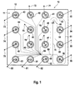
- the microfluid system 10 shown in FIG. 1 includes a microfluid chip 11. This comprises the substrate 12, into which a total of sixteen reservoirs 21 to 36 for the absorption of various fluid substances. There are twelve Reservoirs 21 to 32 for receiving the samples 41 to 52, a reservoir 33 for Inclusion of a buffer 53 serving as a separation medium and that with some buffer Pre-filled reservoirs 34, 35, 36 are provided for receiving waste 54, 55, 56.
- the reservoirs 21 to 36 are fluidly connected to one another by micro-channels form an open network with each other. This means that each of the Reservoirs 21 to 36 are in fluid communication with any other reservoir.
- opening channels in turn open in the area of one Transition point 66 into a single channel, which is in the area of a transfer point 68 divided into two channels.
- the first channel of these two channels opens into the Reservoir 34, which serves to hold the waste 54.
- the second channel of these two Channels open into the injection space of injection site 65, which is shown here as two intersecting channels with a total of four channel parts can be designed.
- There Channel 61 also opens. This opens at his from the injection room opposite end in the reservoir 33. This serves to accommodate the as Separating substance acting buffer 53.
- the junction of the channel 61 in the working channel 70 opens out opposite the injection chamber actual separation of the substances to be analyzed and in turn leads to the reservoir 35 for receiving the waste 55 after the analytical xxx detection site 69 happened.
- the injection space assigned to the injection site 65 is in the exemplary embodiment as a crossing point of the four described above Duct parts designed in this version each at an angle of 90 degrees are arranged offset to each other in a common plane, the each opposite channel parts in the case shown here to each other are aligned.
- Each reservoir 21 to 36 is contacted with an electrode 71 to 86.
- These serve for introducing or discharging electrical voltage and / or electrical current and can also serve as a measuring electrode according to the invention. With their help can be assigned to the current operating behavior of the microfluid system 10 electrical parameters recorded and a controller for regulating the driving force and / or a parameter that can be influenced thereby.
- electrokinetic forces are provided as the driving force, which by introducing or exerting electrical voltages across the electrodes 71 to 86 are introduced or transferred to the respective fluids 41 to 56 can, so that the fluids or components contained therein in the Users desired direction and speed through the open one Network-forming miniature channels can move.
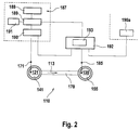
- the microfluid system 110 shown partially schematically in FIG. 2 is special simply designed. This figure also serves to represent the for control and Regulation of the force driving the fluid or the components contained therein and / or the parameters that can be influenced thereby.
- the microfluid system 110 has the one working channel 170 in which the fluid 141 and / or contained therein Components by means of a driving force, here one through the voltage source 188 generated electric or electrokinetic field in the direction (arrow 113) of the working channel 170 are movable.
- the reservoirs 121 and 135 are arranged, which are connected to the working channel 170 in Are in fluid communication.
- Each reservoir 121, 135 is each with an electrode 171 or 185 contacted for introducing or discharging electrical parameters.
- the fluid 141 or can the components contained in the direction (arrow 113) of the working channel 170 can be moved through this and can finally get into the reservoir 135 at its other end as waste 155.
- the Fluid 141 or the constituents contained thereon are essentially identical to one another constant speed through working channel 170 to move one to be able to carry out the most exact analysis possible.
- a characteristic parameter Self-mobility is the identification of a sample component. This material constant leads in connection with the operating parameters field strength and Viscosity of the separation medium at a characteristic speed.
- the effective resistance in the working channel and / or the Conductivity of the fluid 141 can change the power loss that occurs with the Consequence that when a substantially constant voltage is applied to the Electrodes 171 and 185, according to the prior art, depend on the internal and / or external disturbances in the interior of what is also referred to as the fluid thread Fluid flow sets a temperature that is different from the setpoint, so that the instantaneous speed of the sample components is determined by the viscosity in the separation channel depending on the internal and / or external disturbance variables. This can lead to correspondingly different migration speeds of the Lead fluids 141 and / or components contained therein, so that corresponding Errors in the analysis, here essentially in the identification, can occur.
- the electrode 185 is as Measuring electrode, i.e. as a sensor for measuring a fluid 141 assigned or coupled to the fluid 141 and derivable in the region of the fluid 141 Measured variable, here the electric current, provided.
- controller 192 With the sensor 185 is controller 192, here via electrical lines, is coupled.
- This controller 192 obeys a predetermined mathematical algorithm 193 and can also as programmable controller can be designed.
- the controller 192 is in turn one Device for changing the driving force 189, here the electrical Coupled voltage, which forms an actuator.
- the facility for change of the driving force 189 is coupled to the voltage source 188, which the supplies the necessary electrical voltage or the necessary electrical field.
- Control device 191 for controlling the device for changing the driving force connected according to certain preset parameters.
- the facility for change The driving force 189 is also provided with a controller 190 Provision of stabilized, i.e. essentially constant electrical Voltages or currents coupled, which in turn are electrically connected to electrode 171 is coupled.
- the controller 192 receives the current one from the control device 190 Status, which with the help of the predetermined mathematical algorithm 193 Knowledge of the measured current in a current deviation of the power loss and can thus be converted into a correction value.
- This correction value is used to control the device 189 for changing the driving force used.
- the current operating behavior of the Microfluidic system 110 to create a matching superimposed control loop with which it is possible, the power loss occurring and thus that in the fluid thread of the Working channel 170 occurring temperature increase independent of internal and / or to keep external disturbances essentially constant.
- the identification of the sample components can now be expected in anticipation of the constant Temperature conditions and knowing the measurable voltage difference on Separation channel through a time window.
- This time window calculated from the time the injection results from the corresponding mobility in the electrical field the distance in the separation channel from the injection point to the location of the detection.
- the voltage source 188, the device for changing the driving force 189, the control device 191 and the controller device 190 form the voltage supply unit 187. It goes without saying that such a voltage supply unit, at least the device for changing the driving force 189 and the Controller device 190, each or all electrodes 171, 185 even with one with more microfluid system designed as two electrodes, according to user needs can be used multiple times. In such a case the controller 192 also the respective status of that assigned to the electrode 185 Control device 190a supplied.
- the microfluidic system 210 is two, here rectangular intersecting channels designed, in turn with four channel parts 296, 297, 298th and 270 are designed. In the case shown here, the channel parts 296 and 270 are aligned and the channel parts 297 and 298, respectively. Otherwise, the channel parts 296, 297, 298 and 270 each at an angle of 90 degrees to each other in a common Level trained.
- the channel parts 296, 297, 298 and 270 intersect in the intersection 295, which is an injection space for the analyte Make a sample.
- a reservoir 233, 221 and 234 provided, each with the associated channel part in fluid communication stands.
- These reservoirs 221, 233, 234 are each provided with an electrode 271, 283, 284 contacted.
- the reservoir 221 takes the sample 241 to be analyzed and the reservoir 234 serves to receive the Waste 254.
- the reservoir 233 serves to hold the as a separating substance serving buffer 253.
- ESI electro-spray interface
- the Voltage generator 219 For the purpose of mass spectroscopic analysis, the Voltage generator 219 generates a so-called "ESI" voltage, which is used for Generation of the electro-spray 215 is used.
- the ESI voltage is usually from Adjustable to a specific mass spectrometer and the user to adapt to the given conditions. This voltage fluctuates from the device to device, or depending on the conditions of use.
- By means of the Voltage generator 219 generated electric field will be at the end of Channel 270 exiting fluid towards the probe 218 of the mass spectrometer accelerated.
- An electrical spray 215 can be generated in this way, which is a mass spectroscopic analysis of the sample to be analyzed allows.
- measuring electrode serving electrode in the area of the nozzle-side end of the working channel to arrange a control mechanism according to the Representation in connection with FIG. 2 or as follows in connection described with Fig. 4 to enable.
- a control mechanism according to the Representation in connection with FIG. 2 or as follows in connection described with Fig. 4 to enable.
- the use of measuring electrodes on or in the miniaturized microchannels is not uncritical and is not possible in many cases.
- electrolytic Processes and consequently oxidation of the electrodes occur, with the result changed contact resistance.
- the electrical parameters change and changed accordingly the voltage difference across the analysis section in the separation channel.
- Electrode 216 at that measuring point for certain electrical parameters created that is of interest it is proposed to To provide reference channel 299, which at the measuring point of interest in the Working channel 270 opens and then in at the opposite end known manner, a reservoir 237 for receiving a measuring liquid 294 is arranged. With the reservoir 237 is also in a known manner Measuring electrode 300 is contacted. It is understood that in particularly cheaper Embodiment of the invention for the aforementioned purposes already existing Channels and electrodes can be used effectively. By using it such reference channels with the formation of a virtual electrode at the measuring location consequently, the disadvantages described above can be avoided.
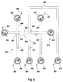
- the microfluid system 310 shown in FIG. 4 represents a partial section of the 1 and is otherwise similar to that Microfluid system 210 designed according to FIG. 3 designed channel parts.
- the Microfluidic system 310 includes a connection channel 401, which ends with the Reservoir 333 is fluid-connected in which the buffer 353 serving as a separating substance is included.
- the connection channel 401 opens at the injection site 365 an injection room. Three further channels open into this injection room, namely the two side channels 402 and 403 and the one here as a separation channel serving working channel 370.
- the working channel 370 points at its from the Injection site 365 facing away from a reservoir 335 for receiving the waste 355 on.
- Channel parts arranged symmetrically to the working channel 370. Penetrate it there are two channels at intersections, so that four each Channel parts flow into a common crossing area.
- Channels are the reservoirs 321, 322, 334 and the reservoirs 332, 336, 337 arranged fluidly connected.
- Each reservoir 321, 322, 332, 333, 334, 335, 336, 337 is contacted with an electrode 371, 372, 382, 383, 384, 385, 386, 397, those for introducing and / or discharging electrical parameters, in particular electrical ones Voltage and / or electrical current are used.
- reservoirs 321, 322 and 332 are samples 341, 342 and 352 and in reservoir 337 is in this case Reference liquid 394 added. It is understood that the reservoir 337 in can generally also be used to hold a sample liquid.
- a great advantage of being an open network of channels fluidly connected to each other ° designed microfluidic systems, microfluid chips in particular are particularly economical Working with a variety of different samples in a small space enable. It is therefore electrophoretic and / or electroosmotic Separation analyzes common that parallel to the separation analysis regarding a particular one Sample substance, for example sample 341, the next operation or the subsequent separation analysis is already prepared in such a way that in a so-called Preinjection phase the next sample, for example sample 352, to an in the smallest possible distance to the injection point 365 arranged transition point 367 is used.
- the reference channel 399 is provided, at the end of which is remote from the transition point 367 the reservoir 337 with the reference liquid 394 or another sample is arranged.
- a type of virtual electrode can be created at the transition point 367. This is achieved by first regulating the electric current (I 2 ) at the second electrode 397 acting as a measuring sensor to the value zero, so that in this way the electric voltage (U 2 ) at the second electrode 397 is measured or detected can be. Any electrical voltage (U 1 ) is applied to the first electrode 382, which is in contact with the reservoir 332 receiving the sample 352.
- the electrical voltage (U 1 ) on the first electrode 382 is then regulated to a voltage value increased by a predetermined voltage value of, for example, 200 volts.
- a predetermined voltage value for example, 200 volts.
- that voltage difference is selected as the predetermined voltage value, which has proven useful or necessary in preliminary tests for the movement of the fluid in question or the constituents contained therein in the intended time.
- the desired voltage difference can be kept essentially constant by means of the controller according to the embodiment shown in FIG. 2, by again the electrical voltage (U 2 ) is measured on the second electrode 397 designed as a measuring electrode and by proceeding in accordance with the steps described above.
- a parallel separation analysis in the separation and working channel 370 requires that certain electrical compensation currents 404 and 405 leading away from the injection site 365 in the direction of the side channels 402 and 403 be set.
- the procedure described above can be meaningfully supplemented in such a way that the electrical current (I 1 ) is also measured at the first electrode 382, then a desired current (I 3 set) at the third electrode 386 using a suitable one Algorithm is calculated, which in the exemplary embodiment is based on the application of Kirchhoff's law, according to which the sum of all currents is always zero and therefore constant.
- the target current (I 3 set) at the third electrode 386 is the sum of the current (I 1 ) measured at the first electrode 382 and a predetermined or predeterminable current (I 4 ) (arrow 404) in the same side channel 402, referred to as the fourth channel.
- the current intensity (l 3 ) at the third electrode 386 is then regulated to the value of the previously calculated target current intensity (I 3 target) by means of a further control device, not shown in the figures.
- the first electrode 382 consequently also serves as a measuring electrode for measuring the electric current (I 1 ).
- a substantially constant voltage can be set, as well as in the side channel 402, which connects the transition point 367 with the injection point 365, a substantially constant, predetermined electrical current I 4 (compensation current 404) can be set is necessary in order to be able to carry out the separation process which runs parallel to the pre-injection phase in the desired manner.
Abstract
Description
- a)
- Regelung des elektrischen Stromes (I2) an der zweiten, als Meßfühler fungierenden Elektrode auf den Wert Null;
- b)
- Messen der elektrischen Spannung (U2) an der zweiten Elektrode, wobei an der ersten Elektrode eine beliebige Spannung (U1) angelegt ist;
- c)
- Regelung der elektrischen Spannung (U1) an der ersten Elektrode dergestalt, daß die Differenz zwischen U1 und U2 einen vorbestimmten Wert erreicht.
- a)
- Regelung des elektrischen Stromes (I2) an der zweiten, als Meßfühler fungierenden Elektrode auf den Wert Null;
- b)
- Messen der elektrischen Spannung (U2)an der zweiten Elektrode, wobei an der ersten Elektrode eine beliebige Spannung (U1)angelegt ist;
- c)
- Regelung der elektrischen Spannung (U1) an der ersten Elektrode dergestalt, daß die Differenz zwischen U1 und U2 einen vorbestimmten Wert erreicht;
- d)
- Messen der elektrischen Stromstärke (I1) an der ersten Elektrode;
- e)
- Berechnen einer Soll-Stromstärke (I3-Soll) an der dritten Elektrode als Summe der an der ersten Elektrode gemessenen Stromstärke (I1) und einer vorbestimmten, dem vierten Kanal zugeordneten Stromstärke (I4);
- f)
- Regelung der Stromstärke (l3) an der dritten Elektrode auf den Wert der zuvor berechneten Soll-Stromstärke (I3-Soll);
- g)
- Wiederholung der Schritte b) bis f).
- Fig. 1
- ein erfindungsgemäßes Mikrofluid-System in Form eines Mikrofluid-Chips mit insgesamt 16 Reservoirs zur Aufnahme von fluiden Substanzen, wobei diese Reservoirs mit einem offenen Netzwerk von Mikrokanälen in Fluidverbindung stehen und mit einem als Arbeitskanal dienenden Trennkanal, das insbesondere in der elektrophoretischen Flüssigkeitsänalyse einsetzbar ist;
- Fig. 2
- eine schematische Darstellung eines einfach aufgebauten Mikrofluid-Systems gemäß der Erfindung, mit Darstellung der für die Steuerung und Regelung der hier elektrischen bzw. elektrokinetischen Prozesse erforderlichen Einrichtungen;
- Fig. 3
- ein weiteres Mikrofluid-System gemäß einer bevorzugten Ausführungsform der Erfindung unter Verwendung eines Referenzkanals und unter Ausbildung einer virtuellen Elektrode am Beispiel einer massenspektrometrischen Analysenanwendung;
- Fig. 4
- ein weiteres Mikrofluid-System mit einem Netzwerk von untereinander fluidverbundenen Mikrokanälen und unter Verwendung eines mit einer Meßelektrode kontaktierten Referenzkanals zur Erläuterung einer besonders vorteilhaften Verfahrensweise.
Claims (13)
- Mikrofluid-System, insbesondere Mikrofluid-Chip, mit wenigstens einem Arbeitskanal in dem ein Fluid und/oder darin enthaltene Bestandteile vermittels einer treibenden Kraft, insbesondere durch Anwendung von Druck, akustischer Energie und/oder eines elektrischen Feldes in Richtung des Arbeitskanals bewegbar sind,
dadurch gekennzeichnet, daß wenigstens ein Meßfühler zur Messung einer dem Fluid zugeordneten und im Bereich des Fluids ableitbaren Meßgröße und wenigstens ein Regler (192) zur Regelung der treibenden Kraft und/oder einer dadurch beeinflußbaren Kenngröße vorgesehen ist, wobei der Regler (192) mit dem Meßfühler und einer Einrichtung zur Veränderung der treibenden Kraft (189) und/oder der dadurch beeinflußbaren Kenngröße gekoppelt ist. - Mikrofluid-System nach Anspruch 1, dadurch gekennzeichnet, daß mit dem Arbeitskanal (70, 170, 270, 370, 400) wenigstens ein in diesen einmündender Meßkanal (299, 399, 400) verbunden ist, der mit dem Meßfühler gekoppelt ist.
- Mikrofluid-System nach einem der Ansprüche 1 oder 2, dadurch gekennzeichnet, daß dieses mit einem offenen Netzwerk von miteinander fluidverbundenen Kanälen ausgebildet ist, wobei wenigstens drei, vorzugsweise vier der Kanäle in einen gemeinsamen, insbesondere punktartig ausgebildeten Kanalraum einmünden, wobei einer der Kanäle als Meßkanal (299, 399, 400) fungiert.
- Mikrofluid-System nach einem der Ansprüche 1 bis 3, dadurch gekennzeichnet, daß der Arbeitskanal (270, 370, 400) mit wenigstens zwei Elektroden zur Ausübung eines elektrischen und/oder magnetischen Feldes auf das Fluid in Verbindung steht, wobei wenigstens eine Arbeitselektrode mit elektrischem Strom und/oder elektrischer Spannung beaufschlagbar ist und wobei wenigstens eine Meßelektrode (297, 397, 382) als Meßfühler dient.
- Mikrofluid-System nach Anspruch 4, dadurch gekennzeichnet, daß alle Elektroden sowohl als Arbeitselektrode als auch als Meßelektrode einsetzbar sind.
- Verfahren zum Transport und der Führung eines Fluids und/oder darin enthaltener Bestandteile in einem Mikrofluid-System, insbesondere einem Mikrofluid-Chip, mit wenigstens einem Arbeitskanal, in dem das Fluid und/oder darin enthaltene Bestandteile vermittels einer treibenden Kraft, insbesondere durch Anwendung von Druck, akustischer Energie, eines elektrischen und/oder eines magnetischen Feldes in Richtung des Arbeitskanals bewegt wird, das bzw. der insbesondere nach einem der Ansprüche 1 bis 5 gestaltet ist,
dadurch gekennzeichnet, daß ein mit einem Meßfühler (283, 397, 382) zur Messung einer dem Fluid zugeordneten und im Bereich des Fluids ableitbaren Meßgröße und einer Einrichtung zur Veränderung der treibenden Kraft (189) und/oder einer dadurch beeinflußbaren Kenngröße gekoppelter Regler (192) die treibende Kraft und/oder die dadurch beeinflußbare Kenngröße regelt. - Verfahren nach Anspruch 6, dadurch gekennzeichnet, daß der Regler (192) die treibende Kraft und/oder die dadurch beeinflußbare Kenngröße derart regelt, daß diese im wesentlichen konstant gehalten wird.
- Verfahren nach Anspruch 6, dadurch gekennzeichnet, daß der Regler (192) die treibende Kraft und/oder die dadurch beeinflußbare Kenngröße derart regelt, daß der Gradient der treibenden Kraft und/oder der Gradient der durch die treibende Kraft beeinflußbaren Kenngröße über einen
bestimmten Abschnitt des Arbeitskanals (170, 270, 370, 400) im wesentlichen konstant gehalten wird bzw. werden. - Verfahren nach Anspruch 6, dadurch gekennzeichnet, daß der Regler (192) die treibende Kraft und/oder die dadurch beeinflußbare Kenngröße dergestalt regelt, daß eine im wesentlichen konstante oder vorbestimmte joulesche Verlustleistung erreicht wird.
- Verfahren nach Anspruch 9 dadurch gekennzeichnet, daß eine Identifikation der Probenbestandteile abhängig von einer am Trennkanal angelegten Differenzspannung erfolgt.
- Verfahren nach einem der Ansprüche 6 bis 10, dadurch gekennzeichnet, daß bei dem als offenes Netzwerk von miteinander fluidverbundenen Kanälen ausgebildeten Mikrofluid-System (10, 210, 310) mehrere Kanäle in einen gemeinsamen, insbesondere punktartig ausgebildeten Kanalraum einmünden, wobei wenigstens einer der Kanäle als Meßkanal (299, 399, 400) fungiert, und wobei die Kanäle an ihrem jeweiligen, von dem Kanalraum entfernten Ende, jeweils mit einer Elektrode (297, 397, 382) zur Ausübung eines elektrischen Feldes auf das Fluid kontaktiert sind, und wobei die Elektroden mit elektrischem Strom und/oder elektrischer Spannung beaufschlagbar sind, und wobei einem ersten Kanal eine erste Elektrode und einem zweiten Kanal eine zweite Elektrode zugeordnet ist, gekennzeichnet durch die folgenden Schritte:a) Regelung des elektrischen Stromes (I2) an der zweiten, als Meßfühler fungierenden Elektrode auf den Wert Null;b) Messen der elektrischen Spannung (U2)an der zweiten Elektrode, wobei an der ersten Elektrode eine beliebige Spannung (U1)angelegt ist;c) Regelung der elektrischen Spannung (U1) an der ersten Elektrode dergestalt, daß die Differenz zwischen U1 und U2 einen vorbestimmten Wert erreicht.
- Verfahren nach einem der Ansprüche 6 bis 10,
dadurch gekennzeichnet, daß
bei dem als offenes Netzwerk von miteinander fluidverbundenen Kanälen ausgebildeten Mikrofluid-System (10, 210, 310) wenigstens vier Kanäle in einen gemeinsamen, insbesondere punktartig ausgebildeten Kanalraum einmünden, wobei wenigstens einer der Kanäle als Meßkanal (299, 399, 400) fungiert, und wobei wenigstens drei der Kanäle an ihrem jeweiligen, von dem Kanalraum entfernten Ende, jeweils mit einer Elektrode (283, 284, 297; 382, 386, 397) zur Ausübung eines elektrischen Feldes auf das Fluid kontaktiert sind, und wobei die Elektroden mit elektrischem Strom und/oder elektrischer Spannung beaufschlagbar sind, und wobei dem
ersten Kanal eine erste Elektrode, dem zweiten Kanal eine zweite Elektrode
und dem dritten Kanal eine dritte Elektrode zugeordnet ist,
gekennzeichnet durch die folgenden Schritte:a) Regelung des elektrischen Stromes (I2) an der zweiten, als Meßfühler fungierenden Elektrode auf den Wert Null;b) Messen der elektrischen Spannung (U2)an der zweiten Elektrode, wobei an der ersten Elektrode eine beliebige Spannung (U1)angelegt ist;c) Regelung der elektrischen Spannung (U1) an der ersten Elektrode dergestalt, daß die Differenz zwischen U1 und U2 einen vorbestimmten Wert erreicht;d) Messen der elektrischen Stromstärke (I1) an der ersten Elektrode;e) Berechnen einer Soll-Stromstärke (I3-Soll) an der dritten Elektrode als Summe der an der ersten Elektrode gemessenen Stromstärke (I1) und einer vorbestimmten, dem vierten Kanal zugeordneten Stromstärke (I4);f) Regelung der Stromstärke (l3) an der dritten Elektrode auf den Wert der zuvor berechneten Soll-Stromstärke (I3-Soll);g) Wiederholung der Schritte b) bis f). - Verfahren nach einem der Ansprüche 6 bis 10,
dadurch gekennzeichnet, daß bei dem als offenes Netzwerk von miteinander fluidverbundenen Kanälen ausgebildeten Mikrofluid-System (210) wenigstens zwei Kanäle (270, 299) zu einem gemeinsamen ESI-punkt führen, wobei wenigstens zwei der Kanäle (270, 299) an ihrem jeweiligen, von dem gemeinsamen Kanalraum entfernten Ende, jeweils mit einer Elektrode (283, 300) zur Ausübung eines elektrischen Feldes auf das Fluid kontaktiert sind, dadurch gekennzeichnet, daß die Summe des elektrischen Stromes in dem gesamten Mikrofluid-System (210) dergestalt geregelt wird, daß ein bestimmter ESI-Reststrom verbleibt.
Priority Applications (4)
| Application Number | Priority Date | Filing Date | Title |
|---|---|---|---|
| EP01115587A EP1270073B1 (de) | 2001-06-28 | 2001-06-28 | Mikrofluid-System mit Regler |
| DE50105368T DE50105368D1 (de) | 2001-06-28 | 2001-06-28 | Mikrofluid-System mit Regler |
| EP04103981A EP1493487A1 (de) | 2001-06-28 | 2001-06-28 | Mikrofluid-System mit ESI-Reststromregelung |
| US10/178,569 US7243670B2 (en) | 2001-06-28 | 2002-06-24 | Microfluidic system |
Applications Claiming Priority (1)
| Application Number | Priority Date | Filing Date | Title |
|---|---|---|---|
| EP01115587A EP1270073B1 (de) | 2001-06-28 | 2001-06-28 | Mikrofluid-System mit Regler |
Related Child Applications (1)
| Application Number | Title | Priority Date | Filing Date |
|---|---|---|---|
| EP04103981A Division EP1493487A1 (de) | 2001-06-28 | 2001-06-28 | Mikrofluid-System mit ESI-Reststromregelung |
Publications (2)
| Publication Number | Publication Date |
|---|---|
| EP1270073A1 true EP1270073A1 (de) | 2003-01-02 |
| EP1270073B1 EP1270073B1 (de) | 2005-02-16 |
Family
ID=8177853
Family Applications (2)
| Application Number | Title | Priority Date | Filing Date |
|---|---|---|---|
| EP04103981A Withdrawn EP1493487A1 (de) | 2001-06-28 | 2001-06-28 | Mikrofluid-System mit ESI-Reststromregelung |
| EP01115587A Expired - Lifetime EP1270073B1 (de) | 2001-06-28 | 2001-06-28 | Mikrofluid-System mit Regler |
Family Applications Before (1)
| Application Number | Title | Priority Date | Filing Date |
|---|---|---|---|
| EP04103981A Withdrawn EP1493487A1 (de) | 2001-06-28 | 2001-06-28 | Mikrofluid-System mit ESI-Reststromregelung |
Country Status (3)
| Country | Link |
|---|---|
| US (1) | US7243670B2 (de) |
| EP (2) | EP1493487A1 (de) |
| DE (1) | DE50105368D1 (de) |
Cited By (1)
| Publication number | Priority date | Publication date | Assignee | Title |
|---|---|---|---|---|
| CN102764676A (zh) * | 2012-07-23 | 2012-11-07 | 西安交通大学 | 非接触式光驱动-双极电极的微流控芯片 |
Families Citing this family (71)
| Publication number | Priority date | Publication date | Assignee | Title |
|---|---|---|---|---|
| US6803568B2 (en) * | 2001-09-19 | 2004-10-12 | Predicant Biosciences, Inc. | Multi-channel microfluidic chip for electrospray ionization |
| US7105810B2 (en) * | 2001-12-21 | 2006-09-12 | Cornell Research Foundation, Inc. | Electrospray emitter for microfluidic channel |
| WO2004034028A2 (en) * | 2002-10-09 | 2004-04-22 | The Board Of Trustees Of The University Of Illinois | Microfluidic systems and components |
| SE0300454D0 (sv) * | 2003-02-19 | 2003-02-19 | Aamic Ab | Nozzles for electrospray ionization and methods of fabricating them |
| US7007710B2 (en) * | 2003-04-21 | 2006-03-07 | Predicant Biosciences, Inc. | Microfluidic devices and methods |
| WO2005024436A1 (ja) * | 2003-09-02 | 2005-03-17 | Nec Corporation | カスタマイズ可能なチップおよびその製造方法 |
| US7537807B2 (en) * | 2003-09-26 | 2009-05-26 | Cornell University | Scanned source oriented nanofiber formation |
| CN100429511C (zh) * | 2004-04-09 | 2008-10-29 | 南京大学 | 一种集成于芯片毛细管电泳的电化学检测方法 |
| US20060022130A1 (en) * | 2004-07-29 | 2006-02-02 | Predicant Biosciences, Inc., A Delaware Corporation | Microfluidic devices and methods with integrated electrical contact |
| US7291824B2 (en) * | 2005-12-22 | 2007-11-06 | Palo Alto Research Center Incorporated | Photosensing throughout energy range and in subranges |
| US7522786B2 (en) * | 2005-12-22 | 2009-04-21 | Palo Alto Research Center Incorporated | Transmitting light with photon energy information |
| US20060060769A1 (en) * | 2004-09-21 | 2006-03-23 | Predicant Biosciences, Inc. | Electrospray apparatus with an integrated electrode |
| US7591883B2 (en) * | 2004-09-27 | 2009-09-22 | Cornell Research Foundation, Inc. | Microfiber supported nanofiber membrane |
| DE102004051394B4 (de) * | 2004-10-21 | 2006-08-17 | Advalytix Ag | Verfahren zur Bewegung von kleinen Flüssigkeitsmengen in Mikrokanälen und Mikrokanalsystem |
| US8695355B2 (en) | 2004-12-08 | 2014-04-15 | California Institute Of Technology | Thermal management techniques, apparatus and methods for use in microfluidic devices |
| US20070012891A1 (en) * | 2004-12-08 | 2007-01-18 | George Maltezos | Prototyping methods and devices for microfluidic components |
| DE102005000835B3 (de) * | 2005-01-05 | 2006-09-07 | Advalytix Ag | Verfahren und Vorrichtung zur Dosierung kleiner Flüssigkeitsmengen |
| EP1833598B1 (de) | 2005-01-05 | 2008-10-08 | Olympus Life Science Research Europa GmbH | Verfahren und vorrichtung zur dosierung und durchmischung kleiner flüssigkeitsmengen |
| US8437582B2 (en) | 2005-12-22 | 2013-05-07 | Palo Alto Research Center Incorporated | Transmitting light with lateral variation |
| US7358476B2 (en) | 2005-12-22 | 2008-04-15 | Palo Alto Research Center Incorporated | Sensing photons from objects in channels |
| US7433552B2 (en) * | 2005-12-22 | 2008-10-07 | Palo Alto Research Center Incorporated | Obtaining analyte information |
| US7386199B2 (en) * | 2005-12-22 | 2008-06-10 | Palo Alto Research Center Incorporated | Providing light to channels or portions |
| US7420677B2 (en) * | 2005-12-22 | 2008-09-02 | Palo Alto Research Center Incorporated | Sensing photon energies of optical signals |
| US7547904B2 (en) * | 2005-12-22 | 2009-06-16 | Palo Alto Research Center Incorporated | Sensing photon energies emanating from channels or moving objects |
| US7315667B2 (en) * | 2005-12-22 | 2008-01-01 | Palo Alto Research Center Incorporated | Propagating light to be sensed |
| US8137626B2 (en) * | 2006-05-19 | 2012-03-20 | California Institute Of Technology | Fluorescence detector, filter device and related methods |
| US8336402B2 (en) * | 2006-08-23 | 2012-12-25 | Georgia Tech Research Corporation | Fluidically-assisted sensor systems for fast sensing of chemical and biological substances |
| WO2008036614A1 (en) * | 2006-09-18 | 2008-03-27 | California Institute Of Technology | Apparatus for detecting target molecules and related methods |
| US7814928B2 (en) * | 2006-10-10 | 2010-10-19 | California Institute Of Technology | Microfluidic devices and related methods and systems |
| CA2580589C (en) | 2006-12-19 | 2016-08-09 | Fio Corporation | Microfluidic detection system |
| US8903472B2 (en) | 2007-01-23 | 2014-12-02 | Dtherapeutics, Llc | Applications of scaling laws of tree structures |
| US9591994B2 (en) | 2007-01-23 | 2017-03-14 | Dtherapeutics, Llc | Systems and methods to obtain a myocardial mass index indicative of an at-risk myocardial region |
| US8821799B2 (en) * | 2007-01-26 | 2014-09-02 | Palo Alto Research Center Incorporated | Method and system implementing spatially modulated excitation or emission for particle characterization with enhanced sensitivity |
| US9164037B2 (en) | 2007-01-26 | 2015-10-20 | Palo Alto Research Center Incorporated | Method and system for evaluation of signals received from spatially modulated excitation and emission to accurately determine particle positions and distances |
| US7936463B2 (en) * | 2007-02-05 | 2011-05-03 | Palo Alto Research Center Incorporated | Containing analyte in optical cavity structures |
| US7554673B2 (en) * | 2007-02-05 | 2009-06-30 | Palo Alto Research Center Incorporated | Obtaining information about analytes using optical cavity output light |
| US7633629B2 (en) | 2007-02-05 | 2009-12-15 | Palo Alto Research Center Incorporated | Tuning optical cavities |
| US8360321B2 (en) | 2007-04-02 | 2013-01-29 | Fio Corporation | System and method of deconvolving multiplexed fluorescence spectral signals generated by quantum dot optical coding technology |
| DE102007018752B4 (de) * | 2007-04-20 | 2011-09-22 | Fraunhofer-Gesellschaft zur Förderung der angewandten Forschung e.V. | Vorrichtung und Verfahren zum geregelten Transport mikrofluidischer Proben |
| CN101821322B (zh) | 2007-06-22 | 2012-12-05 | Fio公司 | 制备量子点掺杂的聚合物微珠的系统和方法 |
| EP2174115B1 (de) | 2007-07-09 | 2013-08-28 | Fio Corporation | Systeme und verfahren zur verbesserung des fluoreszenznachweises von zielmolekülen in einer testprobe |
| GB2453534A (en) * | 2007-10-08 | 2009-04-15 | Shaw Stewart P D | Method for adding solutions to droplets in a microfluidic environment using electric potentials or ultrasound |
| EP2209549A4 (de) | 2007-10-12 | 2014-03-05 | Fio Corp | Strömungsfokussierungsverfahren und system zur bildung von konzentrierten volumina von mikrokügelchen und weiterhin gebildete mikrokügelchen |
| US8320983B2 (en) | 2007-12-17 | 2012-11-27 | Palo Alto Research Center Incorporated | Controlling transfer of objects affecting optical characteristics |
| US8373860B2 (en) | 2008-02-01 | 2013-02-12 | Palo Alto Research Center Incorporated | Transmitting/reflecting emanating light with time variation |
| US8629981B2 (en) | 2008-02-01 | 2014-01-14 | Palo Alto Research Center Incorporated | Analyzers with time variation based on color-coded spatial modulation |
| NL2001431C2 (nl) | 2008-04-02 | 2009-10-05 | Univ Delft Tech | Werkwijze voor het scheiden van een afvalstroom. |
| WO2009134786A2 (en) * | 2008-04-30 | 2009-11-05 | The Board Of Regents Of The University Of Texas System | Quality control method and micro/nano-channeled devices |
| CA2729023C (en) | 2008-06-25 | 2013-02-26 | Fio Corporation | Bio-threat alert system |
| CN105759021A (zh) | 2008-08-29 | 2016-07-13 | Fio公司 | 用于检测生物和环境检测样品的一次性手持式诊断检测设备和相关系统与方法 |
| EP2387721A4 (de) | 2009-01-13 | 2014-05-14 | Fio Corp | Tragbare diagnosetestvorrichtung und verfahren zu deren verwendung mit einer elektronischen vorrichtung sowie testkartusche für schnelle diagnosetests |
| AU2010257118B2 (en) * | 2009-06-04 | 2014-08-28 | Lockheed Martin Corporation | Multiple-sample microfluidic chip for DNA analysis |
| DK2412452T3 (da) | 2010-07-28 | 2013-09-08 | Inashco R & D B V | Separationsapparatur |
| GB2497501A (en) | 2010-10-15 | 2013-06-12 | Lockheed Corp | Micro fluidic optic design |
| US10481069B2 (en) * | 2011-01-03 | 2019-11-19 | Cytonome/St, Llc | Method and apparatus for monitoring and optimizing microfluidic particle sorting |
| NL2006306C2 (en) * | 2011-02-28 | 2012-08-29 | Inashco R & D B V | Eddy current seperation apparatus, separation module, separation method and method for adjusting an eddy current separation apparatus. |
| DE102011076051A1 (de) * | 2011-05-18 | 2012-11-22 | Siemens Aktiengesellschaft | Magnetophoretische Analytselektion und -anreicherung |
| US9029800B2 (en) | 2011-08-09 | 2015-05-12 | Palo Alto Research Center Incorporated | Compact analyzer with spatial modulation and multiple intensity modulated excitation sources |
| US8723140B2 (en) | 2011-08-09 | 2014-05-13 | Palo Alto Research Center Incorporated | Particle analyzer with spatial modulation and long lifetime bioprobes |
| US9322054B2 (en) | 2012-02-22 | 2016-04-26 | Lockheed Martin Corporation | Microfluidic cartridge |
| US9222874B2 (en) * | 2012-06-27 | 2015-12-29 | The United States Of America As Represented By The Secretary Of The Army | Systems and methods for individually trapping particles from air and measuring the optical spectra or other properties of individual trapped particles |
| CN102950037B (zh) * | 2012-11-16 | 2015-05-20 | 北京工业大学 | 一种金属微流控芯片上的微流体驱动方法 |
| CN103447103B (zh) * | 2013-08-27 | 2015-04-22 | 苏州壹达生物科技有限公司 | 一种微电极芯片的封装结构 |
| CN106153701A (zh) * | 2015-04-23 | 2016-11-23 | 宁波大学 | 检测多种亚型猪流感用双驱动耦合模式微流控芯片装置 |
| CN108603828A (zh) | 2015-11-30 | 2018-09-28 | 因塔生物公司 | 用于样品表征的装置和方法 |
| CN105797791B (zh) * | 2016-03-16 | 2017-11-03 | 清华大学深圳研究生院 | 一种微流体离子源芯片及其制备方法 |
| CN107225006B (zh) | 2017-07-03 | 2018-04-03 | 南京岚煜生物科技有限公司 | 基于主动控制液体流动的多通量微流控芯片 |
| KR20200115619A (ko) * | 2018-01-29 | 2020-10-07 | 인타바이오 인코퍼레이티드 | 샘플 특성화를 위한 장치, 방법 및 키트 |
| WO2019232397A1 (en) * | 2018-05-31 | 2019-12-05 | Intabio, Inc. | Software for microfluidic systems interfacing with mass spectrometry |
| WO2020033865A1 (en) * | 2018-08-09 | 2020-02-13 | Hummingbird Nano, Inc. | Microfluidic device and method of manufacture |
| US11285484B2 (en) | 2019-08-12 | 2022-03-29 | Intabio, Llc | Multichannel isoelectric focusing devices and high voltage power supplies |
Citations (4)
| Publication number | Priority date | Publication date | Assignee | Title |
|---|---|---|---|---|
| US5965001A (en) * | 1996-07-03 | 1999-10-12 | Caliper Technologies Corporation | Variable control of electroosmotic and/or electrophoretic forces within a fluid-containing structure via electrical forces |
| US6221226B1 (en) * | 1997-07-15 | 2001-04-24 | Caliper Technologies Corp. | Methods and systems for monitoring and controlling fluid flow rates in microfluidic systems |
| DE19947495A1 (de) * | 1999-10-01 | 2001-05-17 | Hewlett Packard Co | Mikrostrukturankopplung für einen Labor-Mikrochip |
| WO2001042774A2 (en) * | 1999-12-08 | 2001-06-14 | Imperial College Of Science, Technology And Medicine | Potentiometric sensor |
Family Cites Families (11)
| Publication number | Priority date | Publication date | Assignee | Title |
|---|---|---|---|---|
| US4908112A (en) * | 1988-06-16 | 1990-03-13 | E. I. Du Pont De Nemours & Co. | Silicon semiconductor wafer for analyzing micronic biological samples |
| DE59410283D1 (de) * | 1993-11-11 | 2003-06-18 | Aclara Biosciences Inc | Vorrichtung und Verfahren zur elektrophoretischen Trennung von fluiden Substanzgemischen |
| US6001229A (en) * | 1994-08-01 | 1999-12-14 | Lockheed Martin Energy Systems, Inc. | Apparatus and method for performing microfluidic manipulations for chemical analysis |
| US5885470A (en) * | 1997-04-14 | 1999-03-23 | Caliper Technologies Corporation | Controlled fluid transport in microfabricated polymeric substrates |
| AU726987B2 (en) * | 1996-06-28 | 2000-11-30 | Caliper Life Sciences, Inc. | Electropipettor and compensation means for electrophoretic bias |
| US6110343A (en) * | 1996-10-04 | 2000-08-29 | Lockheed Martin Energy Research Corporation | Material transport method and apparatus |
| US6042208A (en) * | 1997-06-03 | 2000-03-28 | Eastman Kodak Company | Image producing apparatus for microfluidic printing |
| US6220747B1 (en) * | 1997-08-14 | 2001-04-24 | Michael Gosselin | Proportional pump system for viscous fluids |
| US6167910B1 (en) * | 1998-01-20 | 2001-01-02 | Caliper Technologies Corp. | Multi-layer microfluidic devices |
| US6605472B1 (en) * | 1998-10-09 | 2003-08-12 | The Governors Of The University Of Alberta | Microfluidic devices connected to glass capillaries with minimal dead volume |
| DE19947496C2 (de) * | 1999-10-01 | 2003-05-22 | Agilent Technologies Inc | Mikrofluidischer Mikrochip |
-
2001
- 2001-06-28 EP EP04103981A patent/EP1493487A1/de not_active Withdrawn
- 2001-06-28 DE DE50105368T patent/DE50105368D1/de not_active Expired - Fee Related
- 2001-06-28 EP EP01115587A patent/EP1270073B1/de not_active Expired - Lifetime
-
2002
- 2002-06-24 US US10/178,569 patent/US7243670B2/en not_active Expired - Lifetime
Patent Citations (4)
| Publication number | Priority date | Publication date | Assignee | Title |
|---|---|---|---|---|
| US5965001A (en) * | 1996-07-03 | 1999-10-12 | Caliper Technologies Corporation | Variable control of electroosmotic and/or electrophoretic forces within a fluid-containing structure via electrical forces |
| US6221226B1 (en) * | 1997-07-15 | 2001-04-24 | Caliper Technologies Corp. | Methods and systems for monitoring and controlling fluid flow rates in microfluidic systems |
| DE19947495A1 (de) * | 1999-10-01 | 2001-05-17 | Hewlett Packard Co | Mikrostrukturankopplung für einen Labor-Mikrochip |
| WO2001042774A2 (en) * | 1999-12-08 | 2001-06-14 | Imperial College Of Science, Technology And Medicine | Potentiometric sensor |
Non-Patent Citations (1)
| Title |
|---|
| RAMSEY R S ET AL: "GENERATING ELECTROSPRAY FROM MICROCHIP DEVICES USING ELECTROOSMOTICPUMPING", ANALYTICAL CHEMISTRY, AMERICAN CHEMICAL SOCIETY. COLUMBUS, US, vol. 69, no. 6, 15 March 1997 (1997-03-15), pages 1174 - 1178, XP000686381, ISSN: 0003-2700 * |
Cited By (2)
| Publication number | Priority date | Publication date | Assignee | Title |
|---|---|---|---|---|
| CN102764676A (zh) * | 2012-07-23 | 2012-11-07 | 西安交通大学 | 非接触式光驱动-双极电极的微流控芯片 |
| CN102764676B (zh) * | 2012-07-23 | 2014-08-06 | 西安交通大学 | 非接触式光驱动-双极电极的微流控芯片 |
Also Published As
| Publication number | Publication date |
|---|---|
| EP1493487A1 (de) | 2005-01-05 |
| US20030000835A1 (en) | 2003-01-02 |
| US7243670B2 (en) | 2007-07-17 |
| DE50105368D1 (de) | 2005-03-24 |
| EP1270073B1 (de) | 2005-02-16 |
Similar Documents
| Publication | Publication Date | Title |
|---|---|---|
| EP1270073A1 (de) | Mikrofluid-System mit Regler | |
| DE60132185T2 (de) | Mehrfach-reservoir-drucksteuersystem | |
| DE60035111T2 (de) | Mikrofluidische systeme mit indizierungskomponenten | |
| DE19947496C2 (de) | Mikrofluidischer Mikrochip | |
| DE60307552T2 (de) | Vorrichtung zum Austragen kleiner Volumen Flüssigkeit einer Mikrokettenlinie entlang | |
| DE60119513T2 (de) | Vorrichtung und verfahren zum einspritzen von flüssigkeiten | |
| DE2363195C3 (de) | ||
| DE69735739T2 (de) | Variable Überwachung von elektroosmotischen und/oder elektroforetischen Kräften in einer in einem Fluidum enthaltenen Anordnung durch elektrische Kräfte | |
| DE4422801A1 (de) | Elektroosmotische Flußsteuerung unter Verwendung von Gegendruck bei der Kapillarelektrophorese | |
| DE19949551C2 (de) | Mikrofluidischer Mikrochip, Energieversorgungseinrichtung und Verfahren zum Betrieb eines mikrofluidischen Mikrochips | |
| DE2363195A1 (de) | Verfahren zur fixierung einer probe in einer bestimmten position bei der gegenflussisotachophorese | |
| EP2049894B1 (de) | Vorrichtung und verfahren zum erfassen von partikeln mit pipette und nanopore | |
| DE112018005405T5 (de) | REGELUNG DES pH-WERTES ZUM DETEKTIEREN VON ANALYTEN | |
| DE10063096C1 (de) | Elektrophoresevorrichtung, Elektrophoreseverfahren unter Verwendung einer Elektrophoresevorrichtung und Verwendung der Elektrophoresevorrichtung | |
| DE2365386A1 (de) | Verfahren zur potentiometrischen analyse einer reihe von fluessigkeitsproben auf eine interessierende substanz | |
| EP3685143B1 (de) | Verfahren zum verformen von deformierbaren körpern und vorrichtungen dazu | |
| DD156846A5 (de) | Verfahren und vorrichtung zum messen von elektrkinetischen erscheinungen an grenzflaechen | |
| DE19826020C2 (de) | Vorrichtung und Verfahren zur miniaturisierten, hochparallelen elektrophoretischen Trennung | |
| DE4314755C2 (de) | Kapillarelektrophoretisches Trennverfahren sowie Vorrichtung zur Durchführung von chemischen oder biochemischen Analysen | |
| DE60026363T2 (de) | Elektroforetische trennungsvorrichtung und zugehöriges verwendungsverfahren | |
| DE4105107A1 (de) | Kontinuierliches durchfluss-analysesystem, insbesondere fliess-injektions-analysesystem und verfahren zum betrieb eines derartigen analysesystems | |
| EP1833598B1 (de) | Verfahren und vorrichtung zur dosierung und durchmischung kleiner flüssigkeitsmengen | |
| DE4244825C2 (de) | Verfahren zur Durchführung einer kapillarelektrophoretischen Bestimmung | |
| WO2008128745A1 (de) | Vorrichtung und verfahren zum geregelten transport mikrofluidischer proben | |
| DE19901041B4 (de) | Vorrichtung und Verfahren zum Messen von Meßgrößen in einer Flüssigkeit |
Legal Events
| Date | Code | Title | Description |
|---|---|---|---|
| PUAI | Public reference made under article 153(3) epc to a published international application that has entered the european phase |
Free format text: ORIGINAL CODE: 0009012 |
|
| AK | Designated contracting states |
Kind code of ref document: A1 Designated state(s): AT BE CH CY DE DK ES FI FR GB GR IE IT LI LU MC NL PT SE TR |
|
| AX | Request for extension of the european patent |
Free format text: AL;LT;LV;MK;RO;SI |
|
| 17P | Request for examination filed |
Effective date: 20030702 |
|
| AKX | Designation fees paid |
Designated state(s): CH DE FR GB LI |
|
| 17Q | First examination report despatched |
Effective date: 20030909 |
|
| GRAP | Despatch of communication of intention to grant a patent |
Free format text: ORIGINAL CODE: EPIDOSNIGR1 |
|
| GRAS | Grant fee paid |
Free format text: ORIGINAL CODE: EPIDOSNIGR3 |
|
| GRAA | (expected) grant |
Free format text: ORIGINAL CODE: 0009210 |
|
| AK | Designated contracting states |
Kind code of ref document: B1 Designated state(s): CH DE FR GB LI |
|
| PG25 | Lapsed in a contracting state [announced via postgrant information from national office to epo] |
Ref country code: FR Free format text: LAPSE BECAUSE OF NON-PAYMENT OF DUE FEES Effective date: 20050216 |
|
| REG | Reference to a national code |
Ref country code: GB Ref legal event code: FG4D Free format text: NOT ENGLISH |
|
| REG | Reference to a national code |
Ref country code: CH Ref legal event code: EP |
|
| GBT | Gb: translation of ep patent filed (gb section 77(6)(a)/1977) |
Effective date: 20050216 |
|
| REF | Corresponds to: |
Ref document number: 50105368 Country of ref document: DE Date of ref document: 20050324 Kind code of ref document: P |
|
| PG25 | Lapsed in a contracting state [announced via postgrant information from national office to epo] |
Ref country code: LI Free format text: LAPSE BECAUSE OF NON-PAYMENT OF DUE FEES Effective date: 20050630 Ref country code: CH Free format text: LAPSE BECAUSE OF NON-PAYMENT OF DUE FEES Effective date: 20050630 |
|
| PLBE | No opposition filed within time limit |
Free format text: ORIGINAL CODE: 0009261 |
|
| STAA | Information on the status of an ep patent application or granted ep patent |
Free format text: STATUS: NO OPPOSITION FILED WITHIN TIME LIMIT |
|
| 26N | No opposition filed |
Effective date: 20051117 |
|
| REG | Reference to a national code |
Ref country code: CH Ref legal event code: PL |
|
| EN | Fr: translation not filed | ||
| PGFP | Annual fee paid to national office [announced via postgrant information from national office to epo] |
Ref country code: DE Payment date: 20070731 Year of fee payment: 7 |
|
| PGFP | Annual fee paid to national office [announced via postgrant information from national office to epo] |
Ref country code: GB Payment date: 20070628 Year of fee payment: 7 |
|
| GBPC | Gb: european patent ceased through non-payment of renewal fee |
Effective date: 20080628 |
|
| PG25 | Lapsed in a contracting state [announced via postgrant information from national office to epo] |
Ref country code: DE Free format text: LAPSE BECAUSE OF NON-PAYMENT OF DUE FEES Effective date: 20090101 |
|
| PG25 | Lapsed in a contracting state [announced via postgrant information from national office to epo] |
Ref country code: GB Free format text: LAPSE BECAUSE OF NON-PAYMENT OF DUE FEES Effective date: 20080628 |