EP1269932A1 - Dental implant assembly - Google Patents
Dental implant assembly Download PDFInfo
- Publication number
- EP1269932A1 EP1269932A1 EP02011136A EP02011136A EP1269932A1 EP 1269932 A1 EP1269932 A1 EP 1269932A1 EP 02011136 A EP02011136 A EP 02011136A EP 02011136 A EP02011136 A EP 02011136A EP 1269932 A1 EP1269932 A1 EP 1269932A1
- Authority
- EP
- European Patent Office
- Prior art keywords
- post
- structure according
- connecting piece
- collar
- grooves
- Prior art date
- Legal status (The legal status is an assumption and is not a legal conclusion. Google has not performed a legal analysis and makes no representation as to the accuracy of the status listed.)
- Granted
Links
Images


Classifications
-
- A—HUMAN NECESSITIES
- A61—MEDICAL OR VETERINARY SCIENCE; HYGIENE
- A61C—DENTISTRY; APPARATUS OR METHODS FOR ORAL OR DENTAL HYGIENE
- A61C8/00—Means to be fixed to the jaw-bone for consolidating natural teeth or for fixing dental prostheses thereon; Dental implants; Implanting tools
- A61C8/0048—Connecting the upper structure to the implant, e.g. bridging bars
- A61C8/005—Connecting devices for joining an upper structure with an implant member, e.g. spacers
- A61C8/0054—Connecting devices for joining an upper structure with an implant member, e.g. spacers having a cylindrical implant connecting part
-
- A—HUMAN NECESSITIES
- A61—MEDICAL OR VETERINARY SCIENCE; HYGIENE
- A61C—DENTISTRY; APPARATUS OR METHODS FOR ORAL OR DENTAL HYGIENE
- A61C8/00—Means to be fixed to the jaw-bone for consolidating natural teeth or for fixing dental prostheses thereon; Dental implants; Implanting tools
- A61C8/0048—Connecting the upper structure to the implant, e.g. bridging bars
- A61C8/005—Connecting devices for joining an upper structure with an implant member, e.g. spacers
- A61C8/0066—Connecting devices for joining an upper structure with an implant member, e.g. spacers with positioning means
-
- A—HUMAN NECESSITIES
- A61—MEDICAL OR VETERINARY SCIENCE; HYGIENE
- A61C—DENTISTRY; APPARATUS OR METHODS FOR ORAL OR DENTAL HYGIENE
- A61C8/00—Means to be fixed to the jaw-bone for consolidating natural teeth or for fixing dental prostheses thereon; Dental implants; Implanting tools
- A61C8/0048—Connecting the upper structure to the implant, e.g. bridging bars
- A61C8/005—Connecting devices for joining an upper structure with an implant member, e.g. spacers
- A61C8/0069—Connecting devices for joining an upper structure with an implant member, e.g. spacers tapered or conical connection
-
- A—HUMAN NECESSITIES
- A61—MEDICAL OR VETERINARY SCIENCE; HYGIENE
- A61C—DENTISTRY; APPARATUS OR METHODS FOR ORAL OR DENTAL HYGIENE
- A61C8/00—Means to be fixed to the jaw-bone for consolidating natural teeth or for fixing dental prostheses thereon; Dental implants; Implanting tools
- A61C8/0048—Connecting the upper structure to the implant, e.g. bridging bars
- A61C8/005—Connecting devices for joining an upper structure with an implant member, e.g. spacers
- A61C8/006—Connecting devices for joining an upper structure with an implant member, e.g. spacers with polygonal positional means, e.g. hexagonal or octagonal
Definitions
- the invention relates to a dental implant structure from a particular ceramic post and a metallic connected to it positively Intermediate piece, which is centered by means of a post and an intermediate piece asserting herself on an inner collar of the post with her head supporting screw is attachable to the implant.
- Such two-part superstructures which by means of precise mating surfaces on one Jaw implants are attached as supports for dental prostheses Bridges, crowns or the like.
- a one-piece ceramic post Opposite a one-piece ceramic post (Instead of ceramic, the use of plastic is also possible)
- Advantage of the two-part construction in that the metallic intermediate piece - in generally made of titanium or a comparable material - a more precise and thus allowing more reliable connection to the implant.
- the diameter of the the central screw receiving implant is for biological reasons, limited in particular by the dimensions of the jaw. Nevertheless, must an exact and torsion-proof support of the structure can be guaranteed.
- a metallic intermediate piece which for example with a Hexagon (DE 44 05 797 C1 and DE 197 13 012 A1) or on another positive manner (DE 42 24 785 C2) in a corresponding front opening of the Engages and is supported on the face of the implant, better accomplish than with a made entirely of ceramic (or plastic) one-piece construction.
- a metallic intermediate piece for example with a Hexagon (DE 44 05 797 C1 and DE 197 13 012 A1) or on another positive manner (DE 42 24 785 C2) in a corresponding front opening of the Engages and is supported on the face of the implant, better accomplish than with a
- two-part implant structures known to date suffer from the disadvantage insufficient security against rotation between the post and the intermediate piece. If their connection is not absolutely non-rotatable, the implant structure can be around the Move the central axis. Even a slight movement like that affects the quality and usability of the prosthesis. It is too take into account that large chewing forces act on relatively small areas, so that the usual gluing between post and intermediate piece with the help of a suitable cement can loosen. The same applies to the equally well-known Frictional connection between the post and the intermediate piece.
- the invention aims to provide a permanently secure connection. It is that between the post and the connector is a positive, effective on both sides of a plane passing through the screw axis Protection against rotation is provided. This ensures that too large forces that are eccentrically different to those carried by the body
- the prosthesis acts, the connection between the post and the intermediate piece can't loosen up. A twisting of the prosthesis - with that of her enclosed post - opposite the intermediate piece and the implant practically impossible.
- the posts are on the post and on Interlocking projections or recesses arranged.
- the arrangement can advantageously be made so that the intermediate piece on its end face facing the post has partially annular axial projections, engage the key-like grooves in the posts.
- the arrangement is such that the post with an outer collar an annular portion of the Intermediate pieces overlaps in the axial direction, and that in the inner surface of the ring collar and recesses in the outer surface of the section Recording wedging material are provided.
- Form the recesses Bags that are at least partially opposite each other and one in Record circumferentially acting peg, which in particular is formed from in-situ curing material.
- FIG. 1 shows a dental implant structure in its with an implant 1 screwed state.
- the structure consists of the connector 2, the Post 3 and the screw 4 connecting everything.
- the connector 2 is rotatably connected to both the implant 1 and the post 3, and positive.
- the metallic preferably made of titanium Connection piece 2 (Fig. 2-7) an end shaped as a hexagon 5, with which it is in the implant engages; securing the position relative to the implant 1 is used subsequent ring collar 6 with a conical end face.
- the post 3 facing and engaging in this has Connector 2 first - following the collar 6 - one in essentially cylindrical collar 7 and following this one Outer cone 8, the base diameter of which is somewhat smaller than the diameter of the collar 7.
- On the free end face 9 of the outer cone 8 are axial Projections 10 are arranged, which in particular FIGS. 3 and 7 removable partial ring shape.
- a through hole 11 passes through it Connector 2 along its entire axial length.
- the projections 10 on the connector 2 correspond to recesses 12 which in an annular collar 13 is provided in the interior of the post 3; on the other, conical side of the collar 13 is supported accordingly trained head 14 of the screw 4 and finds his abutment there.
- an inner cone 15 which the outer cone 8 of Connector 2 corresponds.
- the subsequent cylindrical one Section 16 has a larger diameter and corresponds to that Annular collar 7 of the connecting piece 2. With its end face annular surface 17 lies the post 3 on the facing ring surface of the collar 6 on Connector 2 and receives a precise support in this way.
- the post 3 essentially expands from this end face conical upwards; the gums lie there when installed.
- the upper larger part of the post of smaller diameter is usually used the actual denture attached.
- FIGS. 9-16 and which explains the second aspect of the invention Embodiment corresponds in its basic structure to the above . described The same or at least corresponding elements are therefore included the same reference numerals and are not repeated here described.
- the design of the is different from the first exemplary embodiment Connection between the post 3 and the connector 2.
- a shorter outer cone 8 on the one in the Basic shape cylindrical section 20 follows.
- section 20 there is a Annular groove 21 embedded, on the other hand are 90 ° apart, ie even distributed around the circumference, four flattenings 22 are provided, which are in the middle of the Extend connecting piece 2 circularly into the outer cone 8.
- the Flattenings 22 form together with the inner surface of the cylindrical Section 16 recesses for receiving a wedging material, for example a cement introduced during assembly; The same applies to the Annular groove 21 or those not cut away by the flattenings 22 Sections.
- the post 3 in turn overlaps with an outer collar 23 - over the entire circumference - the part of the connector 2. Seine facing it The inner surface has a connection to the end ring surface 17 with which the Post 3 sits on the implant 1, two stepped cylindrical areas.
- the area 25 following the annular surface 17 has a larger diameter than the adjoining area 26, in which several are semicircular in cross section Grooves 24 are evenly distributed on the circumference. in the when assembled, the grooves 24 form with the flattenings pocket-shaped recesses into which a wedging material is introduced is, for example, a cement common in the dental field.
- An uneven number of grooves and flattening ensures that it is in any rotational relative position of Connector 2 and post 3 to form at least one Recess comes.
Abstract
Description
Die Erfindung betrifft einen Dentalimplantat-Aufbau aus einem insbesondere keramischen Pfosten und einem damit formschlüssig verbundenen metallischen Zwischenstück, der mittels einer den Pfosten und das Zwischenstück zentrisch durchsetzenden, sich an einem Innen-Ringbund des Pfostens mit ihrem Kopf abstützenden Schraube am Implantat befestigbar ist.The invention relates to a dental implant structure from a particular ceramic post and a metallic connected to it positively Intermediate piece, which is centered by means of a post and an intermediate piece asserting herself on an inner collar of the post with her head supporting screw is attachable to the implant.
Solche zweiteiligen Aufbauten, die mittels genauer Passflächen an einem Kieferimplantat befestigt werden, sind als Träger von Dentalprothesen wie Brücken, Kronen o. dgl. bekannt. Gegenüber einem einteiligen Keramikpfosten (statt Keramik ist auch die Verwendung von Kunststoff möglich) besteht der Vorteil des zweiteiligen Aufbaus darin, dass das metallische Zwischenstück - im allgemeinen aus Titan oder einem vergleichbaren Werkstoff - einen exakteren und damit zuverlässigeren Anschluss an das Implantat erlaubt. Der Durchmesser des die zentrale Schraube aufnehmenden Implantats ist aus biologischen Gründen, insbesondere durch die Abmessungen des Kiefers begrenzt. Gleichwohl muss eine exakte und verdrehsichere Abstützung des Aufbaus gewährleistet sein. Das ist mit einem metallischen Zwischenstück, welches beispielsweise mit einem Sechskant (DE 44 05 797 C1 und DE 197 13 012 A1) oder auf eine andere formschlüssige Weise (DE 42 24 785 C2) in eine entsprechende Stirnöffnung des Implantats eingreift und sich auf der Stirnfläche des Implantats abstützt, besser zu bewerkstelligen als mit einem insgesamt aus Keramik (oder Kunststoff) hergestellten einstückigen Aufbau. Für die Verbindung des Zwischenstücks zum Pfosten - also auf der anderen Stirnseite des Zwischenstücks - steht ein größerer Durchmesser zur Verfügung.Such two-part superstructures, which by means of precise mating surfaces on one Jaw implants are attached as supports for dental prostheses Bridges, crowns or the like. Opposite a one-piece ceramic post (Instead of ceramic, the use of plastic is also possible) Advantage of the two-part construction in that the metallic intermediate piece - in generally made of titanium or a comparable material - a more precise and thus allowing more reliable connection to the implant. The diameter of the the central screw receiving implant is for biological reasons, limited in particular by the dimensions of the jaw. Nevertheless, must an exact and torsion-proof support of the structure can be guaranteed. The is with a metallic intermediate piece, which for example with a Hexagon (DE 44 05 797 C1 and DE 197 13 012 A1) or on another positive manner (DE 42 24 785 C2) in a corresponding front opening of the Engages and is supported on the face of the implant, better accomplish than with a made entirely of ceramic (or plastic) one-piece construction. For connecting the intermediate piece to the post - So on the other end of the adapter - there is a larger one Diameter available.
Bislang bekannte zweiteilige Implantataufbauten leiden jedoch an dem Nachteil unzureichender Verdrehsicherheit zwischen dem Pfosten und dem Zwischenstück. Ist deren Verbindung nicht absolut drehfest, kann sich der Implantataufbau um die Zentralachse bewegen. Selbst eine geringe derartige Bewegung aber beeinträchtigt die Qualität und Brauchbarkeit der Prothese. Dabei ist zu berücksichtigen, dass große Kaukräfte auf relativ kleine Flächen wirken, so dass die übliche Verklebung zwischen Pfosten und Zwischenstück mit Hilfe eines geeigneten Zements sich lockern kann. Gleiches gilt für die ebenso bekannte Reibschlussverbindung zwischen dem Pfosten und dem Zwischenstück. Zwar ist es aus der schon erwähnten DE 197 13 012 A1 auch bekannt, einen Keramikkörper mittels eines Keramikstiftes an einem als Zwischenstück dienenden Aufbauteil formschlüssig festzulegen, jedoch bildet dieser gewissermaßen punktförmige Formschluss keine ausreichende Verdrehsicherung, schon gar nicht auf Dauer.However, two-part implant structures known to date suffer from the disadvantage insufficient security against rotation between the post and the intermediate piece. If their connection is not absolutely non-rotatable, the implant structure can be around the Move the central axis. Even a slight movement like that affects the quality and usability of the prosthesis. It is too take into account that large chewing forces act on relatively small areas, so that the usual gluing between post and intermediate piece with the help of a suitable cement can loosen. The same applies to the equally well-known Frictional connection between the post and the intermediate piece. Although is it is also known from DE 197 13 012 A1 already mentioned, a Ceramic body by means of a ceramic pin on a serving as an intermediate piece To fix the structural part in a form-fitting manner, however, this forms to a certain extent punctiform positive locking not sufficient protection against rotation, least of all in the long run.
Die Erfindung will eine dauerhaft sichere Verbindung angeben. Sie besteht darin, dass zwischen dem Pfosten und dem Verbindungsstück eine formschlüssige, beidseitig einer die Schraubenachse durchsetzenden Ebene wirksame Verdrehsicherung vorgesehen ist. Auf diese Weise ist sichergestellt, dass auch große Kräfte, die unterschiedlich exzentrisch auf die vom Aufbau getragene Prothese wirken, die Verbindung zwischen dem Pfosten und dem Zwischenstück nicht lockern können. Ein Verdrehen der Prothese - mit dem von ihr umschlossenen Pfosten - gegenüber dem Zwischenstück und dem Implantat ist damit praktisch ausgeschlossen. The invention aims to provide a permanently secure connection. It is that between the post and the connector is a positive, effective on both sides of a plane passing through the screw axis Protection against rotation is provided. This ensures that too large forces that are eccentrically different to those carried by the body The prosthesis acts, the connection between the post and the intermediate piece can't loosen up. A twisting of the prosthesis - with that of her enclosed post - opposite the intermediate piece and the implant practically impossible.
Nach einem Ausführungsaspekt der Erfindung sind am Pfosten und am Verbindungsstück ineinandergreifende Vor- bzw. Rücksprünge angeordnet. Dabei kann die Anordnung vorteilhaft so getroffen werden, dass das Zwischenstück auf seiner dem Pfosten zugewandten Stirnseite teilringförmige axiale Vorsprünge hat, die passfederartig in entsprechende Nuten im Pfosten eingreifen. Damit erfolgt der Formschluss entlang nahezu radialen Flächen, so dass im Drehsinne wirksame Kräfte aufgenommen werden können, ohne wesentliche radiale Komponenten auftreten zu lassen, welche geeignet sein könnten, den Zusammenhalt und die Festigkeit des fragilen Aufbaus zu gefährden.According to an embodiment of the invention are on the post and on Interlocking projections or recesses arranged. there the arrangement can advantageously be made so that the intermediate piece on its end face facing the post has partially annular axial projections, engage the key-like grooves in the posts. With that the Positive locking along almost radial surfaces, so that it works in the direction of rotation Forces can be absorbed without essential radial components let appear, which could be suitable, the cohesion and the Endanger the strength of the fragile structure.
Nach einem zweiten Aspekt der Erfindung ist die Anordnung derart getroffen, dass der Pfosten mit einem äußeren Ringbund einen ringförmigen Abschnitt des Zwischenstücke in Achsrichtung umfänglich übergreift, und dass in der Innenfläche des Ringbundes und in der Außenfläche des Abschnitts Ausnehmungen zur Aufnahme verkeilenden Werkstoffs vorgesehen sind. Die Ausnehmungen bilden Taschen, die mindestens teilweise einander gegenüberliegen und einen in Umfangsrichtung formschlüssig wirkenden Pflock aufnehmen, der insbesondere aus in situ aushärtendem Material gebildet wird. Um sicherzustellen, dass sich im gewünschten Einbauzustand mindestens eine derartige Pflock- oder Keiltasche bildet, weil sich die Ausnehmungen der Partner zumindest teilweise gegenüberliegen, ist vorzugsweise vorgesehen, dass eine ungleiche Anzahl solcher Ausnehmungen einerseits am Pfosten, andererseits am Zwischenstück ausgebildet sind.According to a second aspect of the invention, the arrangement is such that the post with an outer collar an annular portion of the Intermediate pieces overlaps in the axial direction, and that in the inner surface of the ring collar and recesses in the outer surface of the section Recording wedging material are provided. Form the recesses Bags that are at least partially opposite each other and one in Record circumferentially acting peg, which in particular is formed from in-situ curing material. To ensure that the desired installation condition at least one such peg or wedge pocket forms because the recesses of the partners at least partially opposite, it is preferably provided that an unequal number such recesses on the one hand on the post, on the other hand on the intermediate piece are trained.
Weitere bevorzugte Ausführungen beider Erfindungsaspekte sind Gegenstand von Unteransprüchen.Further preferred embodiments of both aspects of the invention are the subject of Dependent claims.
Die Zeichnung veranschaulicht die Erfindung an Ausführungsbeispielen. Darin zeigt:
- Fig. 1
- einen Längsschnitt durch ein Implantat mit einem Aufbau gemäß dem ersten Aspekt der Erfindung;
- Fig. 2
- eine demgegenüber vergrößerte Darstellung (halb Längsschnitt, halb Seitenansicht) des zugehörigen Verbindungsstücks;
- Fig. 3
- eine Stirnansicht in Richtung des Pfeiles III in Fig. 2;
- Fig. 4
- eine Stirnansicht in Richtung des Pfeiles IV in Fig. 2;
- Fig. 5
- eine Seitenansicht in Richtung des Pfeiles V in Fig. 4;
- Fig. 6
- eine perspektivische Ansicht des Verbindungsstücks von der Implantatseite her;
- Fig. 7
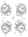
- perspektivische Ansichten (a - d) des Verbindungsstücks von der Aufbauseite her;
- Fig. 8
- eine perspektivische Ansicht des Pfostens von der Seite des Verbindungsstücks her;
- Fig. 9
- einen der Fig. 1 entsprechenden Längsschnitt durch ein Implantat mit dem Aufbau gemäß dem zweiten Aspekt der Erfindung;
- Fig. 10
- eine Darstellung (teils Längsschnitt, teils Seitenansicht) des Verbindungsstücks analog Fig. 2;
- Fig. 11
- eine Stirnansicht in Richtung des Pfeiles 11 in Fig. 10;
- Fig. 12
- eine Stirnansicht in Richtung des Pfeiles XII in Fig. 10;
- Fig. 13
- eine Seitenansicht in Richtung des Pfeiles XIII in Fig. 12;
- Fig. 14
- eine perspektivische Ansicht des Verbindungsstücks von der Implantatseite her;
- Fig. 15
- perspektivische Ansichten (a - d) des Verbindungsstücks von der Pfostenseite her; und
- Fig. 16
- eine perspektivische Ansicht des Pfostens von der Seite des Verbindungsstücks her:
- Fig. 1
- a longitudinal section through an implant with a structure according to the first aspect of the invention;
- Fig. 2
- an enlarged representation (half longitudinal section, half side view) of the associated connector;
- Fig. 3
- an end view in the direction of arrow III in Fig. 2;
- Fig. 4
- an end view in the direction of arrow IV in Fig. 2;
- Fig. 5
- a side view in the direction of arrow V in Fig. 4;
- Fig. 6
- a perspective view of the connector from the implant side;
- Fig. 7
- perspective views (a - d) of the connector from the construction side;
- Fig. 8
- a perspective view of the post from the side of the connector;
- Fig. 9
- a longitudinal section corresponding to FIG 1 through an implant with the structure according to the second aspect of the invention.
- Fig. 10
- a representation (partly longitudinal section, partly side view) of the connector analogous to FIG. 2;
- Fig. 11
- an end view in the direction of
arrow 11 in Fig. 10; - Fig. 12
- an end view in the direction of arrow XII in Fig. 10;
- Fig. 13
- a side view in the direction of arrow XIII in Fig. 12;
- Fig. 14
- a perspective view of the connector from the implant side;
- Fig. 15
- perspective views (a - d) of the connector from the post side; and
- Fig. 16
- a perspective view of the post from the side of the connector:
Figur 1 zeigt einen Dentalimplantat-Aufbau in seinem mit einem Implantat 1
verschraubten Zustand. Der Aufbau besteht aus dem Verbindungsstück 2, dem
Pfosten 3 und der alles verbindenden Schraube 4. Das Verbindungsstück 2 ist
sowohl mit dem Implantat 1 als auch mit dem Pfosten 3 drehfest verbunden, und
zwar formschlüssig.FIG. 1 shows a dental implant structure in its with an implant 1
screwed state. The structure consists of the
Zu diesem Zweck hat das metallische, vorzugsweise aus Titan bestehende
Verbindungsstück 2 (Fig. 2 - 7) ein als Sechskant 5 geformtes Ende, mit dem es in
das Implantat eingreift; der Lagesicherung gegenüber dem Implantat 1 dient ein
anschließender Ringbund 6 mit einer konischen Stirnseite. Auf seiner anderen,
dem Pfosten 3 zugewandten und in diesen eingreifenden Seite hat das
Verbindungsstück 2 zunächst - im Anschluss an den Ringbund 6 - einen im
wesentlichen zylindrischen Ringbund 7 und im Anschluss hieran einen
Außenkonus 8, dessen Basisdurchmesser etwas kleiner ist als der Durchmesser
des Ringbundes 7. Auf der freien Stirnseite 9 des Außenkonus' 8 sind axiale
Vorsprünge 10 angeordnet, welche eine insbesondere den Fig. 3 und 7
entnehmbare Teilringform haben. Eine Durchgangsbohrung 11 durchsetzt das
Verbindungsstück 2 auf seiner gesamten axialen Länge.For this purpose, the metallic, preferably made of titanium
Connection piece 2 (Fig. 2-7) an end shaped as a
Den Vorsprüngen 10 am Verbindungsstück 2 entsprechen Rücksprünge 12, die in
einem Ringbund 13 im Innern des Pfostens 3 vorgesehen sind; auf der anderen,
konischen Seite des Ringbundes 13 stützt sich der entsprechend konisch
ausgebildete Kopf 14 der Schraube 4 ab und findet dort sein Widerlager. Zu der
dem Verbindungsstück 2 zugewandten Öffnung des Pfostens 3 hin schließt sich
an den Ringbund 13 ein Innenkonus 15 an, welcher dem Außenkonus 8 des
Verbindungsstücks 2 entspricht. Der sich hieran anschließende zylindrische
Abschnitt 16 hat wiederum einen größeren Durchmesser und entspricht dem
Ringbund 7 des Verbindungsstücks 2. Mit seiner stirnseitigen Ringfläche 17 liegt
der Pfosten 3 an der ihm zugewandten Ringfläche des Ringbundes 6 am
Verbindungsstück 2 an und erhält auf diese Weise eine präzise Auflage.
Außenseitig erweitert sich der Pfosten 3 von dieser Stirnfläche im wesentlichen
konisch nach oben; dort liegt im Einbauzustand das Zahnfleisch an. Auf dem
oberen größeren Teil des Pfostens von kleinerem Durchmesser wird üblicherweise
die eigentliche Zahnprothese befestigt. The
Das in den Fig. 9 - 16 dargestellte, den zweiten Aspekt der Erfindung erläuternde Ausführungsbeispiel entspricht in seinem grundsätzlichen Aufbau dem vorstehend beschriebenen. Gleiche oder jedenfalls entsprechende Elemente sind daher mit denselben Bezugszeichen bezeichnet und werden hier nicht noch einmal beschrieben.That which is illustrated in FIGS. 9-16 and which explains the second aspect of the invention Embodiment corresponds in its basic structure to the above . described The same or at least corresponding elements are therefore included the same reference numerals and are not repeated here described.
Unterschiedlich gegenüber dem ersten Ausführungsbeispiel ist die Ausbildung der
Verbindung zwischen dem Pfosten 3 und dem Verbindungsstück 2. Bei diesem
schließt sich an den Ringbund 7 ein kürzerer Außenkonus 8 an, auf den ein in der
Grundform zylindrischer Abschnitt 20 folgt. In den Abschnitt 20 ist einerseits eine
Ringnut 21 eingelassen, andererseits sind darin im 90°-Abstand, also gleichmäßig
am Umfang verteilt, vier Abplattungen 22 vorgesehen, die sich zur Mitte des
Verbindungsstücks 2 hin kreisförmig in den Außenkonus 8 erstrecken. Die
Abplattungen 22 bilden zusammen mit der Innenfläche des zylindrischen
Abschnitts 16 Ausnehmungen zur Aufnahme eines verkeilenden Werkstoffs, etwa
eines bei der Montage eingebrachten Zements; Entsprechendes gilt für die
Ringnut 21 bzw. deren nicht durch die Abplattungen 22 weggeschnittenen
Abschnitte.The design of the is different from the first exemplary embodiment
Connection between the
Der Pfosten 3 seinerseits übergreift mit einem äußeren Ringbund 23 - über den
gesamten Umfang - den ihm zugewandten Teil des Verbindungsstücks 2. Seine
Innenfläche weist im Anschluss an die stirnseitige Ringfläche 17, mit der der
Pfosten 3 auf dem Implantat 1 aufsitzt, zwei gestufte zylindrische Bereiche auf.
Der auf die Ringfläche 17 folgende Bereich 25 hat einen größeren Durchmesser
als der anschließende Bereich 26, in dem mehrere im Querschnitt halbrundförmige
Nuten 24 am Umfang gleichmäßig verteilt angeordnet sind. Im
zusammengebauten Zustand bilden die Nuten 24 mit den Abplattungen
taschenförmige Ausnehmungen, in die ein verkeilender Werkstoff eingebracht
wird, beispielsweise ein im Dentalbereich üblicher Zement. Eine ungleiche Anzahl
von Nuten und Abplattungen gewährleistet, dass es in jeder Dreh-Relativlage von
Verbindungsstück 2 und Pfosten 3 zur Bildung mindestens einer solchen
Ausnehmung kommt.The
Claims (11)
dadurch gekennzeichnet, dass zwischen dem Pfosten (3) und dem Verbindungsstück (2) eine formschlüssige, beidseitig einer die Schraubenachse durchsetzenden Ebene wirksame Verdrehsicherung (10, 12) vorgesehen ist.Dental implant structure made up of a ceramic post (3) in particular and a metallic connecting piece (2) connected to it in a form-fitting manner, which with its head (14) on a inner annular collar (13) of the post, which penetrates centrally through the post and the connecting piece. supporting screw (4) can be fastened to the implant (1),
characterized in that between the post (3) and the connecting piece (2) there is provided a positive anti-rotation device (10, 12) which is effective on both sides of a plane passing through the screw axis.
Applications Claiming Priority (2)
| Application Number | Priority Date | Filing Date | Title |
|---|---|---|---|
| DE20110768U | 2001-06-29 | ||
| DE20110768U DE20110768U1 (en) | 2001-06-29 | 2001-06-29 | Dental implant-abutment |
Publications (2)
| Publication Number | Publication Date |
|---|---|
| EP1269932A1 true EP1269932A1 (en) | 2003-01-02 |
| EP1269932B1 EP1269932B1 (en) | 2006-06-14 |
Family
ID=7958691
Family Applications (1)
| Application Number | Title | Priority Date | Filing Date |
|---|---|---|---|
| EP02011136A Expired - Fee Related EP1269932B1 (en) | 2001-06-29 | 2002-05-21 | Dental implant assembly |
Country Status (4)
| Country | Link |
|---|---|
| EP (1) | EP1269932B1 (en) |
| AT (1) | ATE329546T1 (en) |
| DE (2) | DE20110768U1 (en) |
| ES (1) | ES2266346T3 (en) |
Cited By (22)
| Publication number | Priority date | Publication date | Assignee | Title |
|---|---|---|---|---|
| JP2004283552A (en) * | 2002-11-13 | 2004-10-14 | Implant Innovations Inc | Dental implant and dental method |
| EP1656904A1 (en) | 2004-11-16 | 2006-05-17 | Straumann Holding AG | Dental implant system |
| WO2008101705A1 (en) * | 2007-02-22 | 2008-08-28 | Sybron Implant Solutions Gmbh | Stud blank for a dental implant |
| WO2008129512A1 (en) * | 2007-04-23 | 2008-10-30 | Avinent Implant System, S. L. | Transepithelial spacing device for tooth implants |
| JP2009527339A (en) * | 2006-02-24 | 2009-07-30 | ジマー デンタル, インコーポレイテッド | Ceramic / metal dental abutment |
| CN101524294B (en) * | 2008-03-07 | 2011-01-05 | 宝钰生技股份有限公司 | Combined type artificial abutment |
| EP2213258A3 (en) * | 2009-02-03 | 2011-05-04 | Mis-Implants Technologies Ltd | Dental abutment with indentation for inhibition of crestal bone remodeling |
| EP1928345B1 (en) * | 2005-09-27 | 2011-05-25 | Ziterion GmbH | Dental Implant |
| WO2011069671A2 (en) | 2009-12-10 | 2011-06-16 | Cera M Gmbh | Dental implant |
| US8113835B2 (en) * | 2009-04-21 | 2012-02-14 | Pou Yu Biotechnology Co., Ltd. | Abutment assembly for dental implant |
| EP2529692A1 (en) * | 2011-05-31 | 2012-12-05 | GC Corporation | Dental abutment |
| EP2601906A1 (en) | 2011-12-06 | 2013-06-12 | Straumann Holding AG | Abutment inlay |
| GB2509135A (en) * | 2012-12-21 | 2014-06-25 | Nobel Biocare Services Ag | An abutment with conical metal adapter |
| GB2509136A (en) * | 2012-12-21 | 2014-06-25 | Nobel Biocare Services Ag | Dental component with metal adapter |
| LU92312B1 (en) * | 2013-11-20 | 2015-05-21 | Dentaire Hornbeck Jacques Sarl Lab | Dental implant |
| US9149347B2 (en) | 2009-07-27 | 2015-10-06 | Straumann Holding Ag | Abutment for a dental implant |
| EP2793732B1 (en) | 2011-12-21 | 2017-06-28 | bredent medical GmbH & Co. KG | Dental implant abutment and adhesive-bonding base therefor |
| US10149741B2 (en) | 2012-12-21 | 2018-12-11 | Nobel Biocare Services Ag | Method of attaching a dental component to a dental implant |
| US20200229904A1 (en) * | 2007-04-23 | 2020-07-23 | Nobel Biocare Services Ag | Dental implant |
| CN113648093A (en) * | 2021-09-23 | 2021-11-16 | 西安工程大学 | Adjustable-direction and platform-transfer high-stability nuclear-shaped base station and central screw |
| US11602420B2 (en) * | 2013-08-05 | 2023-03-14 | Norman Ho Kwong Kwan | Method for simultaneously installing a monolithic dental prosthesis on multiple dental implants |
| WO2023242739A1 (en) | 2022-06-13 | 2023-12-21 | Maxon International Ag | Connector system for a dental implant |
Families Citing this family (1)
| Publication number | Priority date | Publication date | Assignee | Title |
|---|---|---|---|---|
| EP3456286B1 (en) * | 2017-09-18 | 2020-04-01 | Bernd Single | Abutment and abutment system |
Citations (10)
| Publication number | Priority date | Publication date | Assignee | Title |
|---|---|---|---|---|
| EP0313222A2 (en) * | 1987-09-24 | 1989-04-26 | Steven Gorgas Detsch | Dental implant attachment system |
| US5049073A (en) * | 1988-11-25 | 1991-09-17 | Nikola Lauks | Device for fastening a set of teeth to a jawbone of a patient |
| US5281140A (en) * | 1991-01-02 | 1994-01-25 | Core-Vent Corporation | Multi-part, multi-positionable abutment for use with dental implants |
| FR2745998A1 (en) * | 1996-03-13 | 1997-09-19 | Prosis Sa | Dental prosthesis support with anti=rotation mechanism |
| US6102702A (en) * | 1998-12-28 | 2000-08-15 | Aubrey Clinton Folsom, Jr. | Quick tightening abutment lock |
| US6168435B1 (en) * | 1998-10-26 | 2001-01-02 | Implant Innovations, Inc. | Ceramic dental abutments with a metallic core |
| US6227856B1 (en) * | 1997-01-27 | 2001-05-08 | Implant Innovations, Inc. | Abutment and coping system for use with dental implants |
| US6244867B1 (en) * | 1998-11-24 | 2001-06-12 | Sulzer Dental Inc. | Multi-part, multi-positionable abutment for use with dental implants |
| US6250922B1 (en) * | 1998-07-30 | 2001-06-26 | Sulzer Dental Inc. | Two-piece dental abutment with removable cuff |
| WO2001050977A1 (en) * | 2000-01-13 | 2001-07-19 | Robert Laux | Construction post and fastening device for use in tooth prosthetics or implantology |
Family Cites Families (5)
| Publication number | Priority date | Publication date | Assignee | Title |
|---|---|---|---|---|
| DE4224785C2 (en) * | 1992-07-27 | 1997-04-30 | Imz Fertigung Vertrieb | Endosseous dental implant for a fixed denture and insertion tool |
| DE4443484C2 (en) * | 1994-01-18 | 1999-10-28 | Eska Implants Gmbh & Co | Total tooth replacement implant |
| DE4405797C1 (en) * | 1994-02-23 | 1995-05-18 | Friatec Keramik Kunststoff | Dental implant with reliable seal |
| DE19713012C2 (en) * | 1997-03-27 | 2003-12-04 | Friadent Gmbh | Dental implant |
| DE29911168U1 (en) * | 1999-06-26 | 1999-10-28 | Fischer Horst | Superstructure for anchoring a ceramic structure on a dental implant |
-
2001
- 2001-06-29 DE DE20110768U patent/DE20110768U1/en not_active Expired - Lifetime
-
2002
- 2002-05-21 ES ES02011136T patent/ES2266346T3/en not_active Expired - Lifetime
- 2002-05-21 DE DE50207165T patent/DE50207165D1/en not_active Expired - Lifetime
- 2002-05-21 AT AT02011136T patent/ATE329546T1/en not_active IP Right Cessation
- 2002-05-21 EP EP02011136A patent/EP1269932B1/en not_active Expired - Fee Related
Patent Citations (10)
| Publication number | Priority date | Publication date | Assignee | Title |
|---|---|---|---|---|
| EP0313222A2 (en) * | 1987-09-24 | 1989-04-26 | Steven Gorgas Detsch | Dental implant attachment system |
| US5049073A (en) * | 1988-11-25 | 1991-09-17 | Nikola Lauks | Device for fastening a set of teeth to a jawbone of a patient |
| US5281140A (en) * | 1991-01-02 | 1994-01-25 | Core-Vent Corporation | Multi-part, multi-positionable abutment for use with dental implants |
| FR2745998A1 (en) * | 1996-03-13 | 1997-09-19 | Prosis Sa | Dental prosthesis support with anti=rotation mechanism |
| US6227856B1 (en) * | 1997-01-27 | 2001-05-08 | Implant Innovations, Inc. | Abutment and coping system for use with dental implants |
| US6250922B1 (en) * | 1998-07-30 | 2001-06-26 | Sulzer Dental Inc. | Two-piece dental abutment with removable cuff |
| US6168435B1 (en) * | 1998-10-26 | 2001-01-02 | Implant Innovations, Inc. | Ceramic dental abutments with a metallic core |
| US6244867B1 (en) * | 1998-11-24 | 2001-06-12 | Sulzer Dental Inc. | Multi-part, multi-positionable abutment for use with dental implants |
| US6102702A (en) * | 1998-12-28 | 2000-08-15 | Aubrey Clinton Folsom, Jr. | Quick tightening abutment lock |
| WO2001050977A1 (en) * | 2000-01-13 | 2001-07-19 | Robert Laux | Construction post and fastening device for use in tooth prosthetics or implantology |
Cited By (35)
| Publication number | Priority date | Publication date | Assignee | Title |
|---|---|---|---|---|
| JP2004283552A (en) * | 2002-11-13 | 2004-10-14 | Implant Innovations Inc | Dental implant and dental method |
| EP1656904A1 (en) | 2004-11-16 | 2006-05-17 | Straumann Holding AG | Dental implant system |
| US8540512B2 (en) | 2004-11-16 | 2013-09-24 | Straumann Holding Ag | Dental implant system |
| EP1928345B1 (en) * | 2005-09-27 | 2011-05-25 | Ziterion GmbH | Dental Implant |
| EP2412335A1 (en) * | 2005-09-27 | 2012-02-01 | DENTSPLY Friadent GmbH | Dental implant |
| JP2009527339A (en) * | 2006-02-24 | 2009-07-30 | ジマー デンタル, インコーポレイテッド | Ceramic / metal dental abutment |
| US8439680B2 (en) | 2006-02-24 | 2013-05-14 | Zimmer Dental, Inc. | Ceramic/metallic dental abutment |
| US8668495B2 (en) | 2006-02-24 | 2014-03-11 | Zimmer, Inc. | Ceramic/metallic dental abutment |
| WO2008101705A1 (en) * | 2007-02-22 | 2008-08-28 | Sybron Implant Solutions Gmbh | Stud blank for a dental implant |
| WO2008129512A1 (en) * | 2007-04-23 | 2008-10-30 | Avinent Implant System, S. L. | Transepithelial spacing device for tooth implants |
| US20200229904A1 (en) * | 2007-04-23 | 2020-07-23 | Nobel Biocare Services Ag | Dental implant |
| CN101524294B (en) * | 2008-03-07 | 2011-01-05 | 宝钰生技股份有限公司 | Combined type artificial abutment |
| EP2213258A3 (en) * | 2009-02-03 | 2011-05-04 | Mis-Implants Technologies Ltd | Dental abutment with indentation for inhibition of crestal bone remodeling |
| US8113835B2 (en) * | 2009-04-21 | 2012-02-14 | Pou Yu Biotechnology Co., Ltd. | Abutment assembly for dental implant |
| US9149347B2 (en) | 2009-07-27 | 2015-10-06 | Straumann Holding Ag | Abutment for a dental implant |
| WO2011069671A2 (en) | 2009-12-10 | 2011-06-16 | Cera M Gmbh | Dental implant |
| DE102009057754A1 (en) * | 2009-12-10 | 2011-06-16 | Cera M Gmbh | dental implant |
| DE102009057754B4 (en) * | 2009-12-10 | 2016-01-21 | Cera M Gmbh | dental implant |
| EP2529692A1 (en) * | 2011-05-31 | 2012-12-05 | GC Corporation | Dental abutment |
| US8777617B2 (en) | 2011-05-31 | 2014-07-15 | Gc Corporation | Dental abutment |
| US8684735B2 (en) | 2011-12-06 | 2014-04-01 | Straumann Holding Ag | Abutment inlay |
| EP2601906A1 (en) | 2011-12-06 | 2013-06-12 | Straumann Holding AG | Abutment inlay |
| EP2793732B1 (en) | 2011-12-21 | 2017-06-28 | bredent medical GmbH & Co. KG | Dental implant abutment and adhesive-bonding base therefor |
| WO2014095034A1 (en) * | 2012-12-21 | 2014-06-26 | Nobel Biocare Services Ag | Abutment and method of attaching an abutment to a dental implant |
| US9662186B2 (en) | 2012-12-21 | 2017-05-30 | Nobel Biocare Services Ag | Dental component with metal adapter |
| US9668833B2 (en) | 2012-12-21 | 2017-06-06 | Nobel Biocare Services Ag | Abutment and method of attaching an abutment to a dental implant |
| US10149741B2 (en) | 2012-12-21 | 2018-12-11 | Nobel Biocare Services Ag | Method of attaching a dental component to a dental implant |
| GB2509136A (en) * | 2012-12-21 | 2014-06-25 | Nobel Biocare Services Ag | Dental component with metal adapter |
| GB2509135A (en) * | 2012-12-21 | 2014-06-25 | Nobel Biocare Services Ag | An abutment with conical metal adapter |
| US11730572B2 (en) | 2012-12-21 | 2023-08-22 | Nobel Biocare Services Ag | Apparatus for attaching a dental component to a dental implant |
| US11602420B2 (en) * | 2013-08-05 | 2023-03-14 | Norman Ho Kwong Kwan | Method for simultaneously installing a monolithic dental prosthesis on multiple dental implants |
| LU92312B1 (en) * | 2013-11-20 | 2015-05-21 | Dentaire Hornbeck Jacques Sarl Lab | Dental implant |
| WO2015075137A1 (en) * | 2013-11-20 | 2015-05-28 | Laboratoire Dentaire Hornbeck Jacques S.À.R.L. | Dental implant |
| CN113648093A (en) * | 2021-09-23 | 2021-11-16 | 西安工程大学 | Adjustable-direction and platform-transfer high-stability nuclear-shaped base station and central screw |
| WO2023242739A1 (en) | 2022-06-13 | 2023-12-21 | Maxon International Ag | Connector system for a dental implant |
Also Published As
| Publication number | Publication date |
|---|---|
| ATE329546T1 (en) | 2006-07-15 |
| EP1269932B1 (en) | 2006-06-14 |
| DE50207165D1 (en) | 2006-07-27 |
| ES2266346T3 (en) | 2007-03-01 |
| DE20110768U1 (en) | 2002-11-14 |
Similar Documents
| Publication | Publication Date | Title |
|---|---|---|
| EP1269932A1 (en) | Dental implant assembly | |
| EP2036515B2 (en) | Connecting assembly between a dental implant and an abutment | |
| DE4028857C2 (en) | ||
| EP0711533B1 (en) | Implant | |
| DE3904340C2 (en) | ||
| EP2480161B1 (en) | Dental prosthesis system | |
| EP3509535B1 (en) | Dental prosthesis system | |
| DE4028855A1 (en) | Tooth implant protected against rotation - has post connected by screw union with base body, and distance socket with centering connection | |
| DE1102374B (en) | Insert disk with a cylindrical extension fitting into a circular hole in a rod-shaped component | |
| EP0814725B1 (en) | Tooth implant arrangement | |
| EP0784455B1 (en) | Securing device for tooth implants | |
| WO2018014896A1 (en) | Superstructure support having special inner and outer geometry | |
| EP0308738A1 (en) | Device for fixing a crown onto an implant | |
| DE4326841A1 (en) | Implant set | |
| EP0393324B1 (en) | Fixation device for superstructures | |
| DE10336537B3 (en) | Implant part for a dental implant comprises a one-piece crown arranged in a lockable manner on a post by a form-locking connection, and a spring element acting directly between the post and the crown | |
| EP4054477A1 (en) | System assembly interface | |
| DE10129684A1 (en) | Tooth or jaw segment has base support joined to upright, with screw with conical hollow head containing slots | |
| EP1566152A1 (en) | Dental implant, coated with zirconia | |
| DE3535266C2 (en) | ||
| DE3540188C2 (en) | ||
| DE4028856C1 (en) | Implant for fixed replacement of tooth - comprises metal spacing sleeve upper and lower sections into which implant post is screwed and fixing head is associated with plastic element | |
| DE102005016310B4 (en) | Tour guide | |
| DE19607427C2 (en) | Endosseous single tooth implant | |
| EP0713686A1 (en) | Fixation device for a removable dental prosthesis and process to make it |
Legal Events
| Date | Code | Title | Description |
|---|---|---|---|
| PUAI | Public reference made under article 153(3) epc to a published international application that has entered the european phase |
Free format text: ORIGINAL CODE: 0009012 |
|
| AK | Designated contracting states |
Kind code of ref document: A1 Designated state(s): AT BE CH CY DE DK ES FI FR GB GR IE IT LI LU MC NL PT SE TR |
|
| AX | Request for extension of the european patent |
Free format text: AL;LT;LV;MK;RO;SI |
|
| 17P | Request for examination filed |
Effective date: 20021223 |
|
| AKX | Designation fees paid |
Designated state(s): AT DE ES IT |
|
| RAP1 | Party data changed (applicant data changed or rights of an application transferred) |
Owner name: BEGO SEMADOS GMBH & CO. KG |
|
| GRAP | Despatch of communication of intention to grant a patent |
Free format text: ORIGINAL CODE: EPIDOSNIGR1 |
|
| GRAS | Grant fee paid |
Free format text: ORIGINAL CODE: EPIDOSNIGR3 |
|
| RAP1 | Party data changed (applicant data changed or rights of an application transferred) |
Owner name: BEGO IMPLANT SYSTEMS GMBH & CO. KG |
|
| GRAA | (expected) grant |
Free format text: ORIGINAL CODE: 0009210 |
|
| AK | Designated contracting states |
Kind code of ref document: B1 Designated state(s): AT DE ES IT |
|
| PG25 | Lapsed in a contracting state [announced via postgrant information from national office to epo] |
Ref country code: IT Free format text: LAPSE BECAUSE OF FAILURE TO SUBMIT A TRANSLATION OF THE DESCRIPTION OR TO PAY THE FEE WITHIN THE PRESCRIBED TIME-LIMIT;WARNING: LAPSES OF ITALIAN PATENTS WITH EFFECTIVE DATE BEFORE 2007 MAY HAVE OCCURRED AT ANY TIME BEFORE 2007. THE CORRECT EFFECTIVE DATE MAY BE DIFFERENT FROM THE ONE RECORDED. Effective date: 20060614 |
|
| REF | Corresponds to: |
Ref document number: 50207165 Country of ref document: DE Date of ref document: 20060727 Kind code of ref document: P |
|
| REG | Reference to a national code |
Ref country code: ES Ref legal event code: FG2A Ref document number: 2266346 Country of ref document: ES Kind code of ref document: T3 |
|
| PLBE | No opposition filed within time limit |
Free format text: ORIGINAL CODE: 0009261 |
|
| STAA | Information on the status of an ep patent application or granted ep patent |
Free format text: STATUS: NO OPPOSITION FILED WITHIN TIME LIMIT |
|
| 26N | No opposition filed |
Effective date: 20070315 |
|
| PGFP | Annual fee paid to national office [announced via postgrant information from national office to epo] |
Ref country code: AT Payment date: 20090522 Year of fee payment: 8 |
|
| PG25 | Lapsed in a contracting state [announced via postgrant information from national office to epo] |
Ref country code: AT Free format text: LAPSE BECAUSE OF NON-PAYMENT OF DUE FEES Effective date: 20100521 |
|
| PGFP | Annual fee paid to national office [announced via postgrant information from national office to epo] |
Ref country code: ES Payment date: 20120516 Year of fee payment: 11 |
|
| PGFP | Annual fee paid to national office [announced via postgrant information from national office to epo] |
Ref country code: DE Payment date: 20130603 Year of fee payment: 12 |
|
| PGFP | Annual fee paid to national office [announced via postgrant information from national office to epo] |
Ref country code: IT Payment date: 20130525 Year of fee payment: 12 |
|
| REG | Reference to a national code |
Ref country code: DE Ref legal event code: R119 Ref document number: 50207165 Country of ref document: DE |
|
| REG | Reference to a national code |
Ref country code: DE Ref legal event code: R119 Ref document number: 50207165 Country of ref document: DE Effective date: 20141202 |
|
| PG25 | Lapsed in a contracting state [announced via postgrant information from national office to epo] |
Ref country code: IT Free format text: LAPSE BECAUSE OF NON-PAYMENT OF DUE FEES Effective date: 20140521 Ref country code: DE Free format text: LAPSE BECAUSE OF NON-PAYMENT OF DUE FEES Effective date: 20141202 |
|
| REG | Reference to a national code |
Ref country code: ES Ref legal event code: FD2A Effective date: 20150701 |
|
| PG25 | Lapsed in a contracting state [announced via postgrant information from national office to epo] |
Ref country code: ES Free format text: LAPSE BECAUSE OF NON-PAYMENT OF DUE FEES Effective date: 20140522 |