EP1267473A2 - AC induction motor and method of starting same - Google Patents
AC induction motor and method of starting same Download PDFInfo
- Publication number
- EP1267473A2 EP1267473A2 EP02253939A EP02253939A EP1267473A2 EP 1267473 A2 EP1267473 A2 EP 1267473A2 EP 02253939 A EP02253939 A EP 02253939A EP 02253939 A EP02253939 A EP 02253939A EP 1267473 A2 EP1267473 A2 EP 1267473A2
- Authority
- EP
- European Patent Office
- Prior art keywords
- windings
- run
- motor
- current
- stator
- Prior art date
- Legal status (The legal status is an assumption and is not a legal conclusion. Google has not performed a legal analysis and makes no representation as to the accuracy of the status listed.)
- Granted
Links
Images


Classifications
-
- H—ELECTRICITY
- H02—GENERATION; CONVERSION OR DISTRIBUTION OF ELECTRIC POWER
- H02K—DYNAMO-ELECTRIC MACHINES
- H02K17/00—Asynchronous induction motors; Asynchronous induction generators
- H02K17/02—Asynchronous induction motors
- H02K17/04—Asynchronous induction motors for single phase current
- H02K17/08—Motors with auxiliary phase obtained by externally fed auxiliary windings, e.g. capacitor motors
Definitions
- One aspect of the present invention relates to an AC induction motor having a plurality of independently switchable windings, and particularly but not exclusively to an AC induction motor having at least start and run windings. Another aspect relates to a method of switching the windings of such a motor, particularly but not exclusively when starting the motor.
- a problem associated with induction motors is the high inrush current which occurs when the motor is started.
- the inrush current is caused by the high initial slip between the rotating magnetic fields of the stator and the stationary rotor, leading to a low initial back e.m.f.
- the electrical supply and other components must therefore be specified for the high inrush current, even though this only occurs during starting.
- a lower inrush current allows more efficient use of the electrical system.
- a number of methods of reducing the inrush current have been proposed, all of which suffer from drawbacks.
- the inrush current can be reduced to some extent by increasing the electrical resistance of the rotor cage, but this impairs the running performance of the motor.
- Reduced voltage starters supply a low voltage to the windings on starting, which voltage is increased as the motor accelerates.
- One example is the star-delta system, in which the motor winding configuration is switched from an initial star connection to a delta connection.
- the current surge during the connection changeover can be as high as the initial inrush current. This surge is caused by a phase difference between the rotor and stator fluxes, which occurs in conditions of low load inertia or high friction.
- electromechanical starters Many of the problems of the electromechanical starters described above can be overcome with an electronic power controller, but these are generally more expensive and less reliable than electromechanical starters, and may be unsuitable for harsh environments or safety-critical applications.
- the document US-A-4,443,749 discloses a multiple split-phase induction motor having a two-pole start winding, a two-pole run winding and a four-pole run winding.
- To start the motor current is supplied to both the start winding and one of the run windings. Hence, a high inrush current is likely to occur.
- the start winding is disconnected once the motor reaches a predetermined speed.
- WO 99/49563 discloses a dual stator winding induction machine having two separate stator windings with different numbers of poles.
- the aim of this design is to eliminate magnetic coupling between the two windings and to overcome circulating harmonic currents.
- the document GB 2,321,560 discloses a stator with radially displaced sets of windings having a mutually different phase arrangement.
- the document GB 1,014,365 discloses a stator with start windings displaced radially inwardly and offset by 90° from the run windings.
- EP-A-0 499 989 discloses a method of starting a squirrel cage motor by progressively connecting winding branches to the supply voltage.
- a stator for an AC induction motor including a set of start windings and a set of run windings independently switchable from the set of start windings, characterised in that the set of start windings is radially offset from, and has a similar phase arrangement to, the set of run windings.
- the set of start windings has a higher resistance and preferably a greater number of turns than the set of run windings and is displaced radially outwardly from the set of run windings.
- the start windings can therefore make good thermal contact with an outer casing through the stator laminations and are able to dissipate heat effectively.
- the set of run windings is displaced radially from the set of start windings in the same apertures within the laminations of the stator such that the flux linkage of the set of start windings is greater than that of the set of run windings.
- the impedance of the set of start windings is substantially higher than that of the set of run windings and reduces inrush current, whereas the low impedance of the set of run windings allows high performance to be achieved.
- the cross-sectional area of the set of start windings is less than that of the set of run windings.
- a method of starting an AC induction motor having a first set of windings and a second set of windings independently switchable from the first set comprising:
- current is supplied to the second set of windings after the motor has reached a substantially constant speed when driven by the first set of windings.
- first and second set of windings are not identical, circulating currents will be induced when they are both switched on.
- the resultant loss of operating efficiency and excess heat dissipation is insignificant if both sets are switched on for only a short overlap period.
- This period may be set at a predetermined value which is selected to be as small as possible while ensuring that there will be an overlap period under worst case conditions and tolerance of the components.
- a switch controller for starting an AC induction motor having a first set of windings and a second set of windings independently switchable from the first set, the switch controller comprising means for:
- FIG. 1 shows a 60° sector of a cross-section of this motor perpendicular to the rotor axis.
- the motor has six-fold rotational symmetry about the rotor axis.
- a stator consists of stator laminations 6 including stator slots through which the stator windings are wound.
- the stator windings consist of a set of start windings 1 located in a radially outer section of the slots, and a set of run windings 2 located in the remaining, radially inner section of the slots.
- Each set of windings comprises three windings connectable to respective voltage sources with different phase, as shown by the differently shaded sections A, B and C in Figure 1. As can be seen from these sections, the phase connection of the start windings 1 is the same as that of the run windings 2 in each of the slots.
- the start windings 1 are independently switchable from the run windings 2.
- the start windings 1 are of higher resistance and have a greater number of turns than the run windings 2.
- the stator laminations are mounted within, and in good thermal contact with, a thermally conductive housing (not shown) preferably including cooling fins for increasing the surface area of the housing.
- a thermally conductive housing (not shown) preferably including cooling fins for increasing the surface area of the housing.
- the location of the start windings 1 in the radially outer section of the stator slot gives a high thermal conductivity with respect to the housing and therefore more effective heat dissipation. Hence, the risk of overheating when the start winding 1 is subject to inrush current is reduced.
- a rotor comprises a rotor cage consisting of radially outer bars 3 and radially inner bars 4 located in rotor slots within rotor laminations 7, and a rotor shaft 5.
- Figure 2 is a diagram of the same sector, showing lines of flux under start conditions. From this diagram, it can be seen that the flux linkage is at a maximum at the radially outer end of the stator slots so that the winding impedance of the start windings 1 is higher than it would otherwise be if the start windings were positioned in the middle or radially inner portions of the stator slots. The high impedance of the start windings 1 helps to reduce the inrush current.
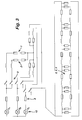
- Figure 3 shows an equivalent circuit of the motor connected to a switching device and a three-phase AC voltage source 10 providing AC voltages V A , V B , V C with a 120° mutual phase relationship.
- the AC voltage source includes feeder resistances 8 for each phase and switches 9 which are arranged independently to connect the set of start windings 1 and the set of run windings 2 to the AC voltage source.
- the equivalent circuit includes an electrical model of the rotor 3, 4, 5.
- Figure 4 is a schematic diagram of the motor 11 with its rotor shaft 5 connected to a load 12.
- Two three-phase contactors 9 1 , 9 2 are arranged to connect the start windings 1 and run windings 2 respectively to the three-phase voltage source 10.
- a rotor speed sensor 14, such as a digital Hall effect sensor, is provided adjacent the shaft 5 and provides an input to a switch controller 13 which controls the switches 9.
- the switch controller 13 may be an electronic controller, or alternatively may be implemented as an electromechanical controller connected to an electromechanical speed sensor.
- the operation of the switch controller 13 and motor 11 during start-up is illustrated in Figures 5, 6 and 7.
- the start winding contactor 9 1 is switched on and power is supplied to the start windings 1.
- the inrush current starts at a high level ( ⁇ 200 A rms in this example) and falls slowly until the rotor speed approaches its maximum, when the current falls to a much lower constant level, at about 0.8 s from starting in this example.
- the switch controller 13 detects, by means of the speed sensor 14, that the rotor shaft 5 has reached a constant or predetermined speed, it closes the run winding contactor 9 2 , at a time T 1 which is about 1.15 s from starting in this example. Power is supplied to the run windings 2 in phase with the power which continues to be supplied to the start windings 1. A low current surge occurs, but at a much lower amplitude ( ⁇ 100 A rms in this example) than the inrush current. Shortly afterwards, at a time T 2 which is about 1.17 s from starting in this example, the start winding contactor 9 1 is opened and power is no longer supplied to the start winding 1 while the motor 11 continues to run normally.
- the interval from time T 1 to time T 2 is predetermined by the switch controller 13 at a constant value which is as small as possible while being sufficient to ensure that power is supplied to the run windings 2 before the start windings 1 are switched off under worst case conditions, and given the tolerances of the components.
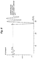
- Figure 8 shows a comparative example where the start winding contactor 9 1 is opened, after the motor 11 has reached its maximum speed, at a time T 3 before the run winding contactor 9 2 is closed at a time T 4 .
- a peak current of over 1000 A occurs, which is much greater than the inrush current peak.
- an inrush current level of less than 3 times rated current was achieved, in comparison with levels of 4 to 5 times rated current in conventional AC induction motors.
- the running efficiency of the motor was approximately 89% as a result of the design of the two separate start and run windings.
- the current surge during switchover was lower than the initial inrush current. The embodiment is therefore able to produce a higher power than prior art AC induction motors for a given AC power source.
- the load 12 may be a variable load which is initially low on starting and increases as the motor accelerates or reaches its operating speed.
- the load 12 may be a hydraulic pump with a start bypass valve. The start bypass valve automatically closes as the pump pressure reaches a predetermined level.
- the motor 11 is particularly suitable for low inertia loads such as pumps, which can give rise to large fluctuations in motor speed during switch-over.
- the present invention is not limited to a three-phase induction motor, but may be applied to other polyphase or single phase induction motors.
Abstract
Description
- One aspect of the present invention relates to an AC induction motor having a plurality of independently switchable windings, and particularly but not exclusively to an AC induction motor having at least start and run windings. Another aspect relates to a method of switching the windings of such a motor, particularly but not exclusively when starting the motor.
- A problem associated with induction motors is the high inrush current which occurs when the motor is started. The inrush current is caused by the high initial slip between the rotating magnetic fields of the stator and the stationary rotor, leading to a low initial back e.m.f. The electrical supply and other components must therefore be specified for the high inrush current, even though this only occurs during starting. Hence, a lower inrush current allows more efficient use of the electrical system. A number of methods of reducing the inrush current have been proposed, all of which suffer from drawbacks.
- The inrush current can be reduced to some extent by increasing the electrical resistance of the rotor cage, but this impairs the running performance of the motor.
- Reduced voltage starters supply a low voltage to the windings on starting, which voltage is increased as the motor accelerates. One example is the star-delta system, in which the motor winding configuration is switched from an initial star connection to a delta connection. However, the current surge during the connection changeover can be as high as the initial inrush current. This surge is caused by a phase difference between the rotor and stator fluxes, which occurs in conditions of low load inertia or high friction.
- Primary resistance starters apply an initial electrical resistance in series with the windings, which is reduced as the motor accelerates. This type of starter suffers from problems of heat generation and excess weight.
- Many of the problems of the electromechanical starters described above can be overcome with an electronic power controller, but these are generally more expensive and less reliable than electromechanical starters, and may be unsuitable for harsh environments or safety-critical applications.
- The document US-A-4,443,749 discloses a multiple split-phase induction motor having a two-pole start winding, a two-pole run winding and a four-pole run winding. To start the motor, current is supplied to both the start winding and one of the run windings. Hence, a high inrush current is likely to occur. The start winding is disconnected once the motor reaches a predetermined speed.
- The document US-A-5,969,497 discloses a starting circuit for an induction motor in which a stationary flux is applied to the rotor through one of the phase windings and current is subsequently applied through another of the phase windings to generate a starting torque. There is no separate start winding; instead, the different phases of the stator winding are switched independently.
- The document WO 99/49563 discloses a dual stator winding induction machine having two separate stator windings with different numbers of poles. The aim of this design is to eliminate magnetic coupling between the two windings and to overcome circulating harmonic currents.
- The document GB 2,321,560 discloses a stator with radially displaced sets of windings having a mutually different phase arrangement.
- The document GB 1,014,365 discloses a stator with start windings displaced radially inwardly and offset by 90° from the run windings.
- The document EP-A-0 499 989 discloses a method of starting a squirrel cage motor by progressively connecting winding branches to the supply voltage.
- According to one aspect of the present invention, there is provided a stator for an AC induction motor, including a set of start windings and a set of run windings independently switchable from the set of start windings, characterised in that the set of start windings is radially offset from, and has a similar phase arrangement to, the set of run windings.
- In one specific aspect, the set of start windings has a higher resistance and preferably a greater number of turns than the set of run windings and is displaced radially outwardly from the set of run windings. The start windings can therefore make good thermal contact with an outer casing through the stator laminations and are able to dissipate heat effectively.
- In another specific aspect, the set of run windings is displaced radially from the set of start windings in the same apertures within the laminations of the stator such that the flux linkage of the set of start windings is greater than that of the set of run windings. Hence, the impedance of the set of start windings is substantially higher than that of the set of run windings and reduces inrush current, whereas the low impedance of the set of run windings allows high performance to be achieved.
- Preferably, the cross-sectional area of the set of start windings is less than that of the set of run windings.
- According to another aspect of the invention, there is provided a method of starting an AC induction motor having a first set of windings and a second set of windings independently switchable from the first set, comprising:
- 1. initially supplying current to the first set of windings without supplying current to the second set of windings, and
- 2. subsequently supplying current to the second set of windings while continuing to supply current to the first set of windings, characterised by subsequent to step b, ceasing to supply current to the first set of windings while continuing to supply current to the second set of windings.
-
- Preferably, current is supplied to the second set of windings after the motor has reached a substantially constant speed when driven by the first set of windings.
- In this way, a high inrush current can be avoided by initially supplying current only to the first set of windings, while a high switchover current can be avoided by maintaining phase between the first and second set of windings and hence between the windings and the rotor.
- Where the first and second set of windings are not identical, circulating currents will be induced when they are both switched on. However, the resultant loss of operating efficiency and excess heat dissipation is insignificant if both sets are switched on for only a short overlap period. This period may be set at a predetermined value which is selected to be as small as possible while ensuring that there will be an overlap period under worst case conditions and tolerance of the components.
- According to another aspect of the present invention, there is provided a switch controller for starting an AC induction motor having a first set of windings and a second set of windings independently switchable from the first set, the switch controller comprising means for:
- a. initially supplying current to the first set of windings without supplying current to the second set of windings, and
- b. subsequently supplying current to the second set of windings while continuing to supply current to the first set of windings; characterised in that the means is further arranged, subsequent to step b, to cease to supply current to the first set of windings while continuing to supply current to the second set of windings.
-
- Specific embodiments of the present invention will now be described with reference to the accompanying drawings, in which:
- Figure 1 is a cross-sectional diagram, perpendicular to the rotor axis, of a sector of the stator and rotor of an AC induction motor;
- Figure 2 is a flux plot diagram of the sector of Figure 1;
- Figure 3 is an equivalent circuit diagram of the AC induction motor connected to a switchable three-phase AC voltage source;
- Figure 4 is a schematic diagram of the motor connected to a switch controller and a load;
- Figure 5 is a timing diagram showing the switching of the motor during start-up;
- Figure 6 is a graph of the current, torque and speed of the motor during start-up;
- Figure 7 is a magnified part of the graph of current in Figure 6 during switchover; and
- Figure 8 is a comparative graph to Figure 7 showing current in an alternative arrangement not in accordance with the invention.
-
- One specific embodiment of the present invention consists of a dual winding three-phase AC induction motor with associated switching circuitry. Figure 1 shows a 60° sector of a cross-section of this motor perpendicular to the rotor axis. The motor has six-fold rotational symmetry about the rotor axis.
- A stator consists of
stator laminations 6 including stator slots through which the stator windings are wound. The stator windings consist of a set ofstart windings 1 located in a radially outer section of the slots, and a set ofrun windings 2 located in the remaining, radially inner section of the slots. Each set of windings comprises three windings connectable to respective voltage sources with different phase, as shown by the differently shaded sections A, B and C in Figure 1. As can be seen from these sections, the phase connection of thestart windings 1 is the same as that of therun windings 2 in each of the slots. - The
start windings 1 are independently switchable from therun windings 2. Thestart windings 1 are of higher resistance and have a greater number of turns than therun windings 2. - The stator laminations are mounted within, and in good thermal contact with, a thermally conductive housing (not shown) preferably including cooling fins for increasing the surface area of the housing. The location of the
start windings 1 in the radially outer section of the stator slot gives a high thermal conductivity with respect to the housing and therefore more effective heat dissipation. Hence, the risk of overheating when the start winding 1 is subject to inrush current is reduced. - A rotor comprises a rotor cage consisting of radially
outer bars 3 and radially inner bars 4 located in rotor slots withinrotor laminations 7, and arotor shaft 5. - Figure 2 is a diagram of the same sector, showing lines of flux under start conditions. From this diagram, it can be seen that the flux linkage is at a maximum at the radially outer end of the stator slots so that the winding impedance of the
start windings 1 is higher than it would otherwise be if the start windings were positioned in the middle or radially inner portions of the stator slots. The high impedance of thestart windings 1 helps to reduce the inrush current. - Figure 3 shows an equivalent circuit of the motor connected to a switching device and a three-phase
AC voltage source 10 providing AC voltages VA, VB, VC with a 120° mutual phase relationship. The AC voltage source includesfeeder resistances 8 for each phase and switches 9 which are arranged independently to connect the set ofstart windings 1 and the set ofrun windings 2 to the AC voltage source. The equivalent circuit includes an electrical model of therotor - Figure 4 is a schematic diagram of the
motor 11 with itsrotor shaft 5 connected to aload 12. Two three-phase contactors start windings 1 and runwindings 2 respectively to the three-phase voltage source 10. Arotor speed sensor 14, such as a digital Hall effect sensor, is provided adjacent theshaft 5 and provides an input to aswitch controller 13 which controls theswitches 9. Theswitch controller 13 may be an electronic controller, or alternatively may be implemented as an electromechanical controller connected to an electromechanical speed sensor. - The operation of the
switch controller 13 andmotor 11 during start-up is illustrated in Figures 5, 6 and 7. To start the motor, thestart winding contactor 91, is switched on and power is supplied to the start windings 1. The inrush current starts at a high level (∼200 A rms in this example) and falls slowly until the rotor speed approaches its maximum, when the current falls to a much lower constant level, at about 0.8 s from starting in this example. - When the
switch controller 13 detects, by means of thespeed sensor 14, that therotor shaft 5 has reached a constant or predetermined speed, it closes therun winding contactor 92, at a time T1 which is about 1.15 s from starting in this example. Power is supplied to therun windings 2 in phase with the power which continues to be supplied to the start windings 1. A low current surge occurs, but at a much lower amplitude (∼100 A rms in this example) than the inrush current. Shortly afterwards, at a time T2 which is about 1.17 s from starting in this example, thestart winding contactor 91 is opened and power is no longer supplied to the start winding 1 while themotor 11 continues to run normally. The interval from time T1 to time T2 is predetermined by theswitch controller 13 at a constant value which is as small as possible while being sufficient to ensure that power is supplied to therun windings 2 before thestart windings 1 are switched off under worst case conditions, and given the tolerances of the components. - Figure 8 shows a comparative example where the
start winding contactor 91 is opened, after themotor 11 has reached its maximum speed, at a time T3 before therun winding contactor 92 is closed at a time T4. A peak current of over 1000 A occurs, which is much greater than the inrush current peak. - In this specific embodiment, an inrush current level of less than 3 times rated current was achieved, in comparison with levels of 4 to 5 times rated current in conventional AC induction motors. The running efficiency of the motor was approximately 89% as a result of the design of the two separate start and run windings. Furthermore, the current surge during switchover was lower than the initial inrush current. The embodiment is therefore able to produce a higher power than prior art AC induction motors for a given AC power source.
- The
load 12 may be a variable load which is initially low on starting and increases as the motor accelerates or reaches its operating speed. For example, theload 12 may be a hydraulic pump with a start bypass valve. The start bypass valve automatically closes as the pump pressure reaches a predetermined level. - The
motor 11 is particularly suitable for low inertia loads such as pumps, which can give rise to large fluctuations in motor speed during switch-over. - The present invention is not limited to a three-phase induction motor, but may be applied to other polyphase or single phase induction motors.
Claims (19)
- A stator for an AC induction motor (11), including a set of start windings (1) and a set of run windings (2) independently switchable from the set of start windings (1), characterised in that the set of start windings (1) is radially offset from, and has a similar phase arrangement to, the set of run windings (2).
- A stator according to claim 1, wherein the set of start windings (1) has the same number of poles as the set of run windings (2).
- A stator according to claim 1 or claim 2, wherein the set of start windings (1) is displaced radially outwardly from the set of run windings (2).
- A stator according to claim 3, including stator laminations (6) in thermal contact with a thermally conductive housing.
- A stator according to claim 3 or 4, wherein the set of start windings (1) and the set of run windings (2) pass through common radially extending slots in the stator, the start windings (1) occupying a radially outer position in the common slots relative to the set of run windings (2).
- A stator according to any one of claims 3 to 5, wherein the flux linkage of the set of start windings (1) is greater than that of the set of run windings (2).
- A stator according to any preceding claim, wherein the impedance of the set of start windings (1) is greater than that of the set of run windings (2).
- A stator according to any preceding claim, wherein the set of start windings (1) comprises a greater number of turns than the set of run windings (2).
- A stator according to any preceding claim, wherein the set of start windings (1) and the set of run windings (2) each comprise a plurality of windings of mutually different phase.
- A stator according to any preceding claim, including switching means (9, 13) for supplying current to the set of start windings (1) to start the motor and supplying current to the set of run windings (2) after the motor (11) is started.
- A stator according to claim 10, wherein the switching means (9, 13) is responsive to a sensor (14) for sensing the speed of the motor (11).
- An AC induction motor having a stator according to any preceding claim.
- A method of starting an AC induction motor (11) having a first set of windings (1) and a second set of windings (2) independently switchable from the first set (1), comprising:a. initially supplying current to the first set of windings (1) without supplying current to the second set of windings (2), andb. subsequently supplying current to the second set of windings (2) while continuing to supply current to the first set of windings (1), characterised byc. subsequent to step b, ceasing to supply current to the first set of windings (1) while continuing to supply current to the second set of windings (2).
- A method according to claim 13, wherein the first set of windings (1) has a similar phase arrangement to the second set of windings (2) and current is supplied to the second set of windings (2) in phase with the current supplied to the first set of windings (1).
- A method according to claim 13 or 14, wherein step b is performed when the motor (11) has reached a substantially constant speed.
- A method according to any one of claims 13 to 15, wherein the first and second set of windings (1, 2) each comprise a plurality of windings of mutually different phase.
- A switch controller (13) for starting an AC induction motor (11) having a first set of windings (1) and a second set of windings (2) independently switchable from the first set (1), the switch controller (13) comprising means for:characterised in that the means is further arranged, subsequent to step b, to cease to supply current to the first set of windings (1) while continuing to supply current to the second set of windings (2).a. initially supplying current to the first set of windings (1) without supplying current to the second set of windings (2), andb. subsequently supplying current to the second set of windings (2) while continuing to supply current to the first set of windings (1);
- A switch controller (13) according to claim 17, wherein the means is arranged to perform step b when the motor (11) has reached a substantially constant speed.
- An AC induction motor (11) including a switch controller (13) according to claim 17 or 18.
Applications Claiming Priority (2)
| Application Number | Priority Date | Filing Date | Title |
|---|---|---|---|
| GB0114665A GB2376573A (en) | 2001-06-15 | 2001-06-15 | AC Induction motor and method of starting same |
| GB0114665 | 2001-06-15 |
Publications (3)
| Publication Number | Publication Date |
|---|---|
| EP1267473A2 true EP1267473A2 (en) | 2002-12-18 |
| EP1267473A3 EP1267473A3 (en) | 2004-08-18 |
| EP1267473B1 EP1267473B1 (en) | 2011-04-06 |
Family
ID=9916697
Family Applications (1)
| Application Number | Title | Priority Date | Filing Date |
|---|---|---|---|
| EP02253939A Expired - Lifetime EP1267473B1 (en) | 2001-06-15 | 2002-06-06 | AC induction motor and method of starting same |
Country Status (4)
| Country | Link |
|---|---|
| US (1) | US6787960B2 (en) |
| EP (1) | EP1267473B1 (en) |
| DE (1) | DE60239653D1 (en) |
| GB (1) | GB2376573A (en) |
Cited By (1)
| Publication number | Priority date | Publication date | Assignee | Title |
|---|---|---|---|---|
| EP1986310A1 (en) * | 2007-04-27 | 2008-10-29 | Honeywell International Inc. | Variable frequency reduced speed variation electric drive |
Families Citing this family (4)
| Publication number | Priority date | Publication date | Assignee | Title |
|---|---|---|---|---|
| US20060267540A1 (en) * | 2005-05-27 | 2006-11-30 | Parker Hannifin Corporation | Pump driven by dual wound variable frequency induction motor |
| US7633260B2 (en) | 2007-10-31 | 2009-12-15 | Hilton Raymond Bacon | Apparatus and method for starting and stopping an AC induction motor |
| US9509237B2 (en) | 2014-05-06 | 2016-11-29 | Tmeic Corporation | AC motor with stator winding tap and methods for starting an AC motor with a variable speed drive |
| CN114070169B (en) * | 2021-11-16 | 2023-08-18 | 烟台杰瑞石油装备技术有限公司 | Fracturing equipment, starting method thereof and fracturing equipment set |
Citations (8)
| Publication number | Priority date | Publication date | Assignee | Title |
|---|---|---|---|---|
| US2900587A (en) * | 1956-02-16 | 1959-08-18 | Moteurs Electr Segal & Cie | Electric motors |
| FR2272514A1 (en) * | 1974-05-20 | 1975-12-19 | Acec | ASYNCHRONOUS MOTOR |
| US4675565A (en) * | 1986-06-02 | 1987-06-23 | Lewus Alexander J | Capacitor-start parallel resonant motor |
| US4890049A (en) * | 1987-07-23 | 1989-12-26 | Siemens Aktiengesellschaft | Circuit and winding arrangement for a multiphase electric rotating field machine |
| EP0397891A1 (en) * | 1988-11-29 | 1990-11-22 | Fanuc Ltd. | Ac spindle motor and method of changing the revolving speed thereof |
| EP0499989A2 (en) * | 1991-02-18 | 1992-08-26 | KONE Elevator GmbH | Procedure for reducing the starting current of a squirrelcage motor, and a squirrelcage motor unit designed for implementing the procedure |
| US5952757A (en) * | 1995-12-04 | 1999-09-14 | General Electric Company | Line start permanent magnet motor |
| US6088905A (en) * | 1993-10-20 | 2000-07-18 | General Electric Company | Method for manufacturing a dynamoelectric machine |
Family Cites Families (13)
| Publication number | Priority date | Publication date | Assignee | Title |
|---|---|---|---|---|
| GB1014365A (en) * | 1963-05-10 | 1965-12-22 | Gen Electric | Improvements in single phase induction type motor |
| JPS5523726A (en) | 1978-08-02 | 1980-02-20 | Hitachi Ltd | Starting of three-phase induction motor |
| US4446416A (en) * | 1979-08-14 | 1984-05-01 | Wanlass Cravens Lamar | Polyphase electric machine having controlled magnetic flux density |
| US4520287A (en) * | 1981-10-27 | 1985-05-28 | Emerson Electric Co. | Stator for a multiple-pole dynamoelectric machine and method of fabricating same |
| US4443749A (en) * | 1982-10-07 | 1984-04-17 | A. O. Smith Corporation | Multiple speed split-phase induction motor |
| JPS62239849A (en) | 1986-04-11 | 1987-10-20 | Takashi Yano | Split-phase type single phase induction motor with transformer winding |
| JP2539053B2 (en) * | 1989-09-25 | 1996-10-02 | 三菱電機株式会社 | Method of manufacturing rotating electric machine |
| JPH0815377B2 (en) * | 1989-10-05 | 1996-02-14 | 株式会社佐竹製作所 | Two-stator three-phase squirrel-cage induction motor |
| US5227710A (en) * | 1989-12-28 | 1993-07-13 | The Alexander J. Lewus Revocable Inter Vivos (Living) Trust | Multiple speed single phase motor |
| GB9603454D0 (en) * | 1996-02-19 | 1996-04-17 | Ea Tech Ltd | Electric motor starting circuit |
| GB2321560A (en) * | 1997-01-28 | 1998-07-29 | John Judson | Alternating current electric motors and generators suitable for variable speed operation. |
| US5883488A (en) * | 1996-07-26 | 1999-03-16 | Emerson Electric Co. | Method and apparatus for multispeed hybrid start switch for a motor |
| US6242884B1 (en) | 1998-03-24 | 2001-06-05 | Wisconsin Alumni Research Foundation | Dual stator winding induction machine drive |
-
2001
- 2001-06-15 GB GB0114665A patent/GB2376573A/en not_active Withdrawn
-
2002
- 2002-06-05 US US10/164,109 patent/US6787960B2/en not_active Expired - Lifetime
- 2002-06-06 EP EP02253939A patent/EP1267473B1/en not_active Expired - Lifetime
- 2002-06-06 DE DE60239653T patent/DE60239653D1/en not_active Expired - Lifetime
Patent Citations (8)
| Publication number | Priority date | Publication date | Assignee | Title |
|---|---|---|---|---|
| US2900587A (en) * | 1956-02-16 | 1959-08-18 | Moteurs Electr Segal & Cie | Electric motors |
| FR2272514A1 (en) * | 1974-05-20 | 1975-12-19 | Acec | ASYNCHRONOUS MOTOR |
| US4675565A (en) * | 1986-06-02 | 1987-06-23 | Lewus Alexander J | Capacitor-start parallel resonant motor |
| US4890049A (en) * | 1987-07-23 | 1989-12-26 | Siemens Aktiengesellschaft | Circuit and winding arrangement for a multiphase electric rotating field machine |
| EP0397891A1 (en) * | 1988-11-29 | 1990-11-22 | Fanuc Ltd. | Ac spindle motor and method of changing the revolving speed thereof |
| EP0499989A2 (en) * | 1991-02-18 | 1992-08-26 | KONE Elevator GmbH | Procedure for reducing the starting current of a squirrelcage motor, and a squirrelcage motor unit designed for implementing the procedure |
| US6088905A (en) * | 1993-10-20 | 2000-07-18 | General Electric Company | Method for manufacturing a dynamoelectric machine |
| US5952757A (en) * | 1995-12-04 | 1999-09-14 | General Electric Company | Line start permanent magnet motor |
Cited By (2)
| Publication number | Priority date | Publication date | Assignee | Title |
|---|---|---|---|---|
| EP1986310A1 (en) * | 2007-04-27 | 2008-10-29 | Honeywell International Inc. | Variable frequency reduced speed variation electric drive |
| US7952316B2 (en) | 2007-04-27 | 2011-05-31 | Honeywell International, Inc. | Variable frequency reduced speed variation electric drive |
Also Published As
| Publication number | Publication date |
|---|---|
| US20020195987A1 (en) | 2002-12-26 |
| EP1267473A3 (en) | 2004-08-18 |
| GB2376573A (en) | 2002-12-18 |
| EP1267473B1 (en) | 2011-04-06 |
| US6787960B2 (en) | 2004-09-07 |
| GB0114665D0 (en) | 2001-08-08 |
| DE60239653D1 (en) | 2011-05-19 |
Similar Documents
| Publication | Publication Date | Title |
|---|---|---|
| US4107583A (en) | Dynamoelectric machine winding arrangements, dynamoelectric machines incorporating same and methods of operating such dynamoelectric machines | |
| US7327048B2 (en) | Hybrid gas turbine engine starter-generator | |
| CA1281065C (en) | Parallel resonant single phase motor | |
| EP0093615B1 (en) | Variable speed rotary electrical machines | |
| US4947072A (en) | Stator winding for two-pole dynamoelectric induction machines | |
| CA2071542C (en) | Multiple-stator induction synchronous motor | |
| CA2075791C (en) | Brushless induction synchronous motor with two stators | |
| MXPA05002085A (en) | Psc motor having a 4/6-pole common winding and having an additional 4-pole winding. | |
| EP1267473B1 (en) | AC induction motor and method of starting same | |
| CN1551463A (en) | Electric driving apparatus | |
| US20040150232A1 (en) | Gas turbine engine starter generator with AC generator and DC motor modes | |
| US8796970B2 (en) | Method for controlling a multiphase electric motor operating in star-connected mode | |
| KR100628008B1 (en) | Capacitor start single phase induction motor with partial winding starting | |
| US3959702A (en) | Starting control system for synchronous motors | |
| KR100698218B1 (en) | Driving circuit of the hybrid induction motor | |
| RU2739874C2 (en) | Engine with permanent magnets and direct starting from mains and method of its connection | |
| KR0169433B1 (en) | Pole changing type of single phase induction motor | |
| US4500825A (en) | Self-starting single-phase synchronous motor | |
| US20040164701A1 (en) | Electrodynamic machines and components therefor and methods of making and using same | |
| EP4142115A1 (en) | Tapped winding method for extended constant horsepower speed range | |
| RU2050684C1 (en) | Sync-async engine | |
| JPS61161991A (en) | Overexciting method for hysteresis motor | |
| RU2089036C1 (en) | Induction motor control gear | |
| US20030151384A1 (en) | 2-start, 4 pole single-phase motor | |
| SU1603516A1 (en) | A.c. electric drive |
Legal Events
| Date | Code | Title | Description |
|---|---|---|---|
| PUAI | Public reference made under article 153(3) epc to a published international application that has entered the european phase |
Free format text: ORIGINAL CODE: 0009012 |
|
| AK | Designated contracting states |
Kind code of ref document: A2 Designated state(s): AT BE CH CY DE DK ES FI FR GB GR IE IT LI LU MC NL PT SE TR |
|
| AX | Request for extension of the european patent |
Free format text: AL;LT;LV;MK;RO;SI |
|
| PUAL | Search report despatched |
Free format text: ORIGINAL CODE: 0009013 |
|
| AK | Designated contracting states |
Kind code of ref document: A3 Designated state(s): AT BE CH CY DE DK ES FI FR GB GR IE IT LI LU MC NL PT SE TR |
|
| AX | Request for extension of the european patent |
Extension state: AL LT LV MK RO SI |
|
| 17P | Request for examination filed |
Effective date: 20041105 |
|
| 17Q | First examination report despatched |
Effective date: 20050209 |
|
| AKX | Designation fees paid |
Designated state(s): DE FR GB |
|
| GRAP | Despatch of communication of intention to grant a patent |
Free format text: ORIGINAL CODE: EPIDOSNIGR1 |
|
| GRAS | Grant fee paid |
Free format text: ORIGINAL CODE: EPIDOSNIGR3 |
|
| GRAA | (expected) grant |
Free format text: ORIGINAL CODE: 0009210 |
|
| AK | Designated contracting states |
Kind code of ref document: B1 Designated state(s): DE FR GB |
|
| REG | Reference to a national code |
Ref country code: GB Ref legal event code: FG4D |
|
| REF | Corresponds to: |
Ref document number: 60239653 Country of ref document: DE Date of ref document: 20110519 Kind code of ref document: P |
|
| REG | Reference to a national code |
Ref country code: DE Ref legal event code: R096 Ref document number: 60239653 Country of ref document: DE Effective date: 20110519 |
|
| PLBE | No opposition filed within time limit |
Free format text: ORIGINAL CODE: 0009261 |
|
| STAA | Information on the status of an ep patent application or granted ep patent |
Free format text: STATUS: NO OPPOSITION FILED WITHIN TIME LIMIT |
|
| 26N | No opposition filed |
Effective date: 20120110 |
|
| REG | Reference to a national code |
Ref country code: DE Ref legal event code: R097 Ref document number: 60239653 Country of ref document: DE Effective date: 20120110 |
|
| REG | Reference to a national code |
Ref country code: FR Ref legal event code: PLFP Year of fee payment: 15 |
|
| REG | Reference to a national code |
Ref country code: FR Ref legal event code: PLFP Year of fee payment: 16 |
|
| REG | Reference to a national code |
Ref country code: FR Ref legal event code: PLFP Year of fee payment: 17 |
|
| REG | Reference to a national code |
Ref country code: GB Ref legal event code: S117 Free format text: REQUEST FILED; REQUEST FOR CORRECTION UNDER SECTION 117 FILED ON 6 NOVEMBER 2018 |
|
| REG | Reference to a national code |
Ref country code: GB Ref legal event code: S117 Free format text: REQUEST FOR CORRECTION UNDER SECTION 117 FILED ON 6 NOVEMBER 2018 NOT PROCEEDED WITH ON 14 NOVEMBER 2018 |
|
| REG | Reference to a national code |
Ref country code: GB Ref legal event code: 732E Free format text: REGISTERED BETWEEN 20181203 AND 20181205 |
|
| REG | Reference to a national code |
Ref country code: DE Ref legal event code: R081 Ref document number: 60239653 Country of ref document: DE Owner name: EATON INTELLIGENT POWER LIMITED, IE Free format text: FORMER OWNER: EATON LTD., TITCHFIELD, HAMPSHIRE, GB |
|
| PGFP | Annual fee paid to national office [announced via postgrant information from national office to epo] |
Ref country code: DE Payment date: 20210519 Year of fee payment: 20 Ref country code: FR Payment date: 20210519 Year of fee payment: 20 |
|
| PGFP | Annual fee paid to national office [announced via postgrant information from national office to epo] |
Ref country code: GB Payment date: 20210519 Year of fee payment: 20 |
|
| REG | Reference to a national code |
Ref country code: DE Ref legal event code: R071 Ref document number: 60239653 Country of ref document: DE |
|
| REG | Reference to a national code |
Ref country code: GB Ref legal event code: PE20 Expiry date: 20220605 |
|
| PG25 | Lapsed in a contracting state [announced via postgrant information from national office to epo] |
Ref country code: GB Free format text: LAPSE BECAUSE OF EXPIRATION OF PROTECTION Effective date: 20220605 |