EP1265420A2 - A method for distinguishing clients in a communication system, a communication system, and a communication device - Google Patents
A method for distinguishing clients in a communication system, a communication system, and a communication device Download PDFInfo
- Publication number
- EP1265420A2 EP1265420A2 EP02396076A EP02396076A EP1265420A2 EP 1265420 A2 EP1265420 A2 EP 1265420A2 EP 02396076 A EP02396076 A EP 02396076A EP 02396076 A EP02396076 A EP 02396076A EP 1265420 A2 EP1265420 A2 EP 1265420A2
- Authority
- EP
- European Patent Office
- Prior art keywords
- access network
- client
- communication system
- examined
- resolution
- Prior art date
- Legal status (The legal status is an assumption and is not a legal conclusion. Google has not performed a legal analysis and makes no representation as to the accuracy of the status listed.)
- Granted
Links
Images


Classifications
-
- H—ELECTRICITY
- H04—ELECTRIC COMMUNICATION TECHNIQUE
- H04L—TRANSMISSION OF DIGITAL INFORMATION, e.g. TELEGRAPHIC COMMUNICATION
- H04L69/00—Network arrangements, protocols or services independent of the application payload and not provided for in the other groups of this subclass
- H04L69/08—Protocols for interworking; Protocol conversion
- H04L69/085—Protocols for interworking; Protocol conversion specially adapted for interworking of IP-based networks with other networks
-
- H—ELECTRICITY
- H04—ELECTRIC COMMUNICATION TECHNIQUE
- H04L—TRANSMISSION OF DIGITAL INFORMATION, e.g. TELEGRAPHIC COMMUNICATION
- H04L69/00—Network arrangements, protocols or services independent of the application payload and not provided for in the other groups of this subclass
- H04L69/08—Protocols for interworking; Protocol conversion
-
- Y—GENERAL TAGGING OF NEW TECHNOLOGICAL DEVELOPMENTS; GENERAL TAGGING OF CROSS-SECTIONAL TECHNOLOGIES SPANNING OVER SEVERAL SECTIONS OF THE IPC; TECHNICAL SUBJECTS COVERED BY FORMER USPC CROSS-REFERENCE ART COLLECTIONS [XRACs] AND DIGESTS
- Y10—TECHNICAL SUBJECTS COVERED BY FORMER USPC
- Y10S—TECHNICAL SUBJECTS COVERED BY FORMER USPC CROSS-REFERENCE ART COLLECTIONS [XRACs] AND DIGESTS
- Y10S707/00—Data processing: database and file management or data structures
- Y10S707/99941—Database schema or data structure
- Y10S707/99943—Generating database or data structure, e.g. via user interface
Definitions
- the present invention relates to a method for distinguishing clients in a communication system comprising at least one wireless access network and at least one wired access network, said at least one wireless access network comprising means for connecting at least one wireless client in communication to said at least one wireless access network, said at least one wired access network comprising means for connecting at least one wired client in communication to said at least one wired access network, and said communication system comprising means for communicating between said at least one wireless access network and said at least one wired access network.
- the invention also relates to a communication system comprising at least one wireless access network and at least one wired access network, said at least one wireless access network comprising means for connecting at least one wireless client in communication to said at least one wireless access network, said at least one wired access network comprising means for connecting at least one wired client in communication to said at least one wired access network, and said communication system comprising means for communicating between said at least one wireless access network and said at least one wired access network.
- the invention further relates to a communication device comprising means for communicating with a communication system comprising at least one wireless access network and at least one wired access network, said at least one wireless access network comprising means for connecting at least one wireless client in communication to said at least one wireless access network, said at least one wired access network comprising means for connecting at least one wired client in communication to said at least one wired access network, and said communication system comprising means for communicating between said at least one wireless access network and said at least one wired access network.
- Such a communication system typically comprises at least one server and a number of clients.
- the clients can communicate with the server and other clients through different parts of the network.
- the wireless access network has one or more access point devices.
- the wireless clients can have access to the wireless access network through the access point devices.
- access point devices typically operate as link layer bridges between a wired access network such as Ethernet and the wireless access network such as WLAN.
- the wired access network and the wireless access network usually belong to a single IP sub-network. Every device (client, server, access point, etc.) connected to the network must have a unique IP address which is used when the device sends packets to the network and when unicast or multicast packets are sent via the network to the device. Normally such an IP sub-network has an address range in which addresses of all the devices of the sub-network belong.
- the invention is based on the idea that a resolution request message is transmitted from a requesting node to the network.
- a resolution reply message is transmitted to the requesting node only if the client belongs to the wired access network.
- a resolution reply message is transmitted to the requesting node only if the client belongs to the wireless access network.
- the method according to the present invention is primarily characterized in that the method comprises at least the following steps:
- a communication system is primarily characterized in that the communication system also comprises:
- a communication device is primarily characterized in that the communication device also comprises:
- the present invention shows remarkable advantages compared to solutions of prior art.
- clients belonging to the wireless access network can be distinguished from clients belonging to the wired access network without the need of performing manual configuration.
- inserting and removing of clients is easier.
- the node of the network can perform the checking which can be performed e.g. every time the node receives a packet which should be forwarded to a client, or a lifetime can be defined for the configuration information of a client wherein the node performs the check only if the lifetime has expired. This latter alternative can e.g. be used to reduce the amount of information to be transmitted in the communication system.
- Fig. 1 shows an example of a communication system 1 according to an advantageous embodiment of the present invention.
- the communication system 1 comprises at least one wireless access network 2 and at least one wired access network 3. It is obvious that there may exist more than one wireless access network and/or more than one wired access network in the communication system in which the present invention can be applied.
- the communication system 1 comprises access points AP1, AP2, AP3 which have transmitting and receiving means for providing communication with wireless clients WC1, WC2 and the wireless access network 2.
- the wireless client WC1, WC2 can, for example, be a wireless terminal having data processing means, such as a laptop PC, and wireless communication means, such as a radio modem.
- Some wireless access networks may comprise one or more access point controllers separate from the access points. The function of the access point controllers is to control the operation of the access points. The communication between the wireless clients and the rest of the communication system is routed via the access point controller(s). However, in Fig. 1 all the access points AP1, AP2, AP3 and (possible) access point controllers are shown as single units.
- the access points AP1, AP2, AP3 are directly connected to the wired network in the communication system 1 of Fig. 1, wherein all the access points AP1, AP2, AP3 can directly communicate with other access points and other devices connected to the wired access network 3.
- a radio connection is arranged between the access point AP1, AP2 and the wireless clients WC1, WC2 for transmitting e.g. signals required for setting up a connection and, during the connection, information, such as data packets of an Internet application.
- the wired access network 3 comprises one or more servers S, one or more routers R and it may also comprise one or more wired clients C.
- the server S controls the operation of the wired access network 3, and it can communicate with other devices connected to the wired access network 3.
- the router R is implemented in such communication systems 1 in which communication with other networks e.g. Internet is necessary.
- the router R routes data packets from the wired and wireless access network to other networks and, respectively, receives packets from other networks and retransmits the received packets to the intended receiver, or to another router.
- a TCP/IP protocol stack is generally used, which can be divided into five functional layers. These five layers are, listed from bottom to top: the physical layer (Layer 1), the link layer (Layer 2), the network layer (Layer 3), the transport layer (Layer 4), and the application layer (Layer 5). All the nodes of the Internet data network contain at least the first three layers. Of these nodes, routers, which are primarily responsible for the couplings of the data network, do not need the transport and application layers. However, hosts, between which the actual data transmission connection is set up, contain all the said five layers. Even though all the upper level layers use the services of the underlying layer for data transmission, logically the corresponding layers of the hosts communicate with each other by using the protocol typical for the layer.
- the actual data transmission is conducted in the physical layer by using a data transmission means, such as a wireless radio network or landline cabling.
- the link layer attends to solutions required by different network technologies, wherein the upper level layers do not have to know how the data transmission network used at a given time is constructed.
- the link layer processes different addressing and frame modes and is responsible for the data transmission between two terminals in the same communication network.
- the task of the network layer is to route packets between terminals in the communication network.
- the network layer provides the coupling between different data networks, wherein the upper level layers do not have to know about the structure of the data network.
- protocols IP Internet Protocol
- ICMP Internet Control Message Protocol
- IGMP Internet Group Management Protocol
- the transport layer provides a generic end-to-end data transmission connection for the application layer.
- the application layer uses for instance a TCP protocol (Transmission Control Protocol) and a UDP protocol (User Datagram Protocol).
- TCP Transmission Control Protocol
- UDP User Datagram Protocol
- the application layer protocols operate above the transport layer and provide application-specific services, such as file transfer services or access network remote login services.
- the application layer protocols operate above the transport layer and provide application-specific services, such as file transfer services or access network remote login services.
- applications running on the application layer in the wireless client WC1 and in the wired host S communicate with each other via the access point AP1.
- HTTP protocol HyperText Transfer Protocol
- HTTP protocol is generally used in the Internet data network for loading and presenting the data contained in so-called home pages in the display device of a computer.
- Other application layer protocols are, for example, Telnet, the file transfer protocol FTP and the simple mail transfer protocol SMTP.
- each client or host has its own identifying IP address.
- the IP address is in the Internet protocol version IPv4 a 32 bit, i.e. 4 byte number which is split into an organization-specific network address and a network-specific device address.
- IPv6 the length of the address fields is increased to 128 bits, which, in practice, means that it is possible to allocate an individual address for all the devices which are connected to the Internet data network.
- An Internet host connected to the Internet data network via a access network 2, 3 has either a permanently specified Internet address or the address is a dynamic address established by the access network server (for example by using dynamic host configuration protocol DHCP).
- the host has to request for an Internet address from the Internet service provider, to which the Internet host is registered. This is conducted, for example, according to a point-to-point protocol PPP.
- PPP point-to-point protocol
- the Internet protocol IP specifies the data transmission in packets ("Datagrams").
- Datagrams data transmission in packets
- the first step is to examine whether the packet is intended precisely for the router or client in question. If the packet is intended precisely for this router or client, the packet is transferred from the network layer to the upper layer in this node. If the packet is intended to another node, a so-called routing algorithm is executed in the network layer for concluding how the packet should be processed. First, it is examined whether the packet is intended for another node in the same network. If this is the case, the node can transmit the packet to the destination address by using the mechanisms of the link layer. Thus, the IP address of the network layer level is connected to the corresponding link layer address by using the so-called address resolution protocol ARP. In this node, the packet is also framed into a packet corresponding to the link layer and transmitted further.
- ARP address resolution protocol
- the routing algorithm runs through a routing table in order to find out to which address the packet should be transmitted.
- the routing table typically contains a so-called default address, to which all such packets are transmitted whose routing address cannot be found in the routing table.
- the transmission of IP packets between different coupled data networks on the network layer level is conducted on the basis of IP addresses.
- the devices connected to the Internet data network also have a so-called link layer address, which is also called a device address.
- link layer address which is also called a device address.
- terminals use link layer services in packet transmission with terminals connected to the same data network, the terminals need the address resolution protocol ARP for connecting the IP addresses to the corresponding link layer addresses.
- the reverse address resolution protocol RARP connects the link layer addresses to the corresponding IP addresses.
- the function of the address resolution protocol ARP depends on the structure of the data transmission connection used at a given time.
- the address resolution program typically uses four different messages: an ARP request, an ARP reply, an RARP request, and an RARP reply.
- a requesting node such as some of the access points AP1, AP2, AP3, needs to find out whether a target node resides on the wireless access network 2 or on the wired access network 3, a resolution request message is formed in the requesting node and transmitted to the wired access network 3. If the requesting node is an access point AP1, AP2, AP3, it transmits the message over the wired network interface NIC2 of the access point AP1, AP2, AP3 (Fig. 7) to the wired access network 3. The requesting node also starts a controlling timer T (Fig. 7).
- the resolution request message can be transmitted as a unicast message addressed directly to the link-layer address of the target node wherein the message comprises the link-layer address of the target node.
- the target node is one of the access points AP1, AP2, AP3 of the wireless access network 2, or one of the wired nodes S, R of the wired access network 3.
- the resolution request message may also be transmitted as a multicast message wherein it comprises a special multicast address. It is also possible to use broadcast transmission wherein the resolution request message is marked as a broadcast message wherein all nodes of the wired access network 3 receive and process the message.
- the target node AP1, AP2, AP3, S, R receives the resolution request message which is either addressed to it or is a broadcast message
- the target node examines the contents of the message.
- the message comprises identification information of the target node.
- the identification information is usually the address of the target node.
- the target node S, R examines whether the identification information of the message equals the identification information of the target node, and if it does the target node will form a resolution reply message.
- the target node will then transmit the resolution reply message preferably as a unicast message to the requesting node.
- the steps of the method of the present invention are advantageously implemented mainly on the link-layer level procedures of the protocol stack of the nodes.
- the lower level layers of the protocol stack perform necessary steps to forward the messages between physical layer and the link-layer of the protocol stack.
- the target node cannot support the resolution request message according to the invention.
- the requesting node When the requesting node receives the resolution reply message, it examines the address of the sender or some other information of the message to find out to which resolution request message the reply was transmitted. The requesting node can then determine that the target node in question is connected to the wired access network 3. The requesting node may store the resolution information of the target node into memory means MEM ( e . g . cache) so that it is not necessary to send the resolution request message every time the requesting node needs to find out on which access network 2, 3 the target node is situated. The requesting node may also define a lifetime for the resolution information.
- MEM e . g . cache
- the requesting node first examines if the lifetime of the resolution information is expired. If it is not yet expired the requesting node uses the stored resolution information. Otherwise, the requesting node sends the resolution request message and waits for an answer.
- the target node does not receive the resolution request message. Neither does any proxy of the wired access network 3 have information of the target node. In that kind of situation the resolution reply message is not transmitted in the wired access network 3, wherein the requesting node will not receive the resolution reply message as is shown in Fig. 3.
- the requesting node may schedule a retransmission timer for the resolution request so that the resolution request message is retransmitted a couple of times if no response has been received.
- the requesting node determines that the target node in question does not belong to the wired access network 3, if the requesting node does not receive a resolution reply message within a certain time period.
- the requesting node can perform the above described checking procedure for more than one target node and save the resolution information of each checked target node.
- RARP Reverse Address Resolution Protocol
- the requesting node can send a RARP request message as the resolution request message in order to resolve whether a target node is on the wired access network.
- Target nodes which are on the wired access network 3 can then reply with a RARP reply message, or if the replying node is a proxy on behalf of the target node, a proxy RARP reply message can be used. If RARP is used, the access points must not forward the resolution request messages over the wireless access network.
- a requesting node such as some of the wired nodes S, R or access points AP1, AP2, AP3 needs to find out whether a target node resides on the wireless access network 2 or on the wired access network 3, a resolution request message is formed e.g. in the link-layer of the requesting node. Then, the requesting node transmits the resolution request message to the wired access network 3.
- the requesting node is an access point AP1, AP2, AP3, it transmits the message over the wired network interface NIC2 of the access point AP1, AP2, AP3 to the wired access network 3.
- This resolution request message can be transmitted as a unicast message addressed directly to the link-layer address of the target node wherein the message comprises the link-layer address of the target node.
- the target node is one of the access points AP1, AP2, AP3 of the wireless access network 2, or one of the wired nodes S, R of the wired access network 3.
- the resolution request message may also be transmitted as a multicast message wherein it comprises a special multicast address. It is also possible to use broadcast transmission wherein the resolution request message is marked as a broadcast message.
- the access points AP1, AP2, AP3 of the wireless access network need to maintain information of wireless clients which are associated with the access point AP1, AP2, AP3.
- an access point AP1, AP2, AP3 receives the resolution request message which is either addressed to it or is a broadcast message, the message is transferred to the link-layer of the protocol stack of the access point AP1, AP2, AP3. Then the link-layer level procedures of the access point AP1, AP2, AP3 examine the contents of the message.
- the message comprises identification information of the target node. In the access point AP1, AP2, AP3 it is examined if the message has information of the target node.
- the access point AP1, AP2, AP3 it is examined which wireless clients are connected with the access point AP1, AP2, AP3. If the identification information of the message indicates that the target node is a wireless client connected to the access point, a resolution reply message is formed in the access point AP1, AP2, AP3 and transmitted to the requesting node over the wired network interface of the access point.
- the requesting node When the requesting node receives the resolution reply message, message is transferred to the link-layer of the protocol stack of the requesting node. Then the link-layer level procedures of the requesting node examine the address of the sender or some other information of the message to find out to which resolution request message the reply was transmitted. The requesting node can then determine that the target node in question is connected to the wireless access network 2. The requesting node may save the resolution information of the target node so that it is not necessary to send the resolution request message every time the requesting node needs to find out on which access network 2, 3 the target node is situated. The requesting node may also define a lifetime for the resolution information.
- the requesting node first examines if the lifetime of the resolution information is expired. If it has not yet expired the requesting node uses the stored resolution information. Otherwise, the requesting node sends the resolution request message and waits for an answer.
- the target node is not in the wireless access network 2, no access point has identification information similar to the identification information of the resolution request message. Therefore the resolution reply message is not formed and transmitted in the wired access network 3 and the requesting node will not receive the resolution reply message as is shown in Fig. 5.
- the requesting node may schedule a retransmission timer for the resolution request so that the resolution request message is retransmitted a couple of times if no response has been received.
- the requesting node determines that the target node in question does not belong to the wireless access network 2, if the requesting node does not receive a resolution reply message within a certain time period.
- the requesting node can perform the above described check for more than one target node and save the resolution information of each checked target node.
- the requesting node can use the resolution information for different purposes. For example, there may exist situations in which transmission of information should be restricted only to devices of the wired access network 3.
- the node When a node of the wired access network receives a packet which should be forwarded to a client, the node first examines the resolution information of the client. If the resolution information indicates that the client is connected to a part of the network where the packet is not allowed to be forwarded, the node will not forward the packet to the client. Otherwise the packet will be forwarded normally.
- the direct transmission between clients of the wireless access network can be prevented by examining at the access point the resolution information prior to packets from one client are forwarded to another client.
- the resolution reply message is transmitted independent of whether the target node is a wireless client or a wired client. This is possible, for example, in a communication system 1 in which the access point AP1, AP2, AP3 transmits the resolution reply message if the target node is a wireless client, and the target node or proxy transmits the resolution reply message if the target node is a wired client. Therefore the requesting device can determine from the sender of the resolution reply message whether the target node is a wireless client or a wired client.
- the appended Fig. 7 presents in a reduced manner the features of the access point AP1, AP2, AP3 which are meaningful when implementing the present invention.
- the hardware part includes, for instance, a microprocessor ⁇ P, memory means MEM, a connection logic I/O, and retransmission timer T.
- the network interface architecture comprises a wireless network interface NIC1 and a wired network interface NIC 2, by means of which the actual physical data transmission connection is established.
- the practical implementation of these network interfaces depends, for instance, on the type of the network interface in question.
- a network interface card intended for a wireless access network comprises a radio modem, or the like, whereby it is possible to set up a wireless data transmission connection to the radio modem of the access network.
- the network interfaces NIC1, NIC2 constitute said physical layer and can also contain features of the link layer.
Abstract
Description
- The present invention relates to a method for distinguishing clients in a communication system comprising at least one wireless access network and at least one wired access network, said at least one wireless access network comprising means for connecting at least one wireless client in communication to said at least one wireless access network, said at least one wired access network comprising means for connecting at least one wired client in communication to said at least one wired access network, and said communication system comprising means for communicating between said at least one wireless access network and said at least one wired access network. The invention also relates to a communication system comprising at least one wireless access network and at least one wired access network, said at least one wireless access network comprising means for connecting at least one wireless client in communication to said at least one wireless access network, said at least one wired access network comprising means for connecting at least one wired client in communication to said at least one wired access network, and said communication system comprising means for communicating between said at least one wireless access network and said at least one wired access network. The invention further relates to a communication device comprising means for communicating with a communication system comprising at least one wireless access network and at least one wired access network, said at least one wireless access network comprising means for connecting at least one wireless client in communication to said at least one wireless access network, said at least one wired access network comprising means for connecting at least one wired client in communication to said at least one wired access network, and said communication system comprising means for communicating between said at least one wireless access network and said at least one wired access network.
- There are communication systems which comprise both wired and wireless access network. Such a communication system typically comprises at least one server and a number of clients. The clients can communicate with the server and other clients through different parts of the network. The wireless access network has one or more access point devices. The wireless clients can have access to the wireless access network through the access point devices. On current wireless access networks access point devices typically operate as link layer bridges between a wired access network such as Ethernet and the wireless access network such as WLAN. The wired access network and the wireless access network usually belong to a single IP sub-network. Every device (client, server, access point, etc.) connected to the network must have a unique IP address which is used when the device sends packets to the network and when unicast or multicast packets are sent via the network to the device. Normally such an IP sub-network has an address range in which addresses of all the devices of the sub-network belong.
- Situations may exist in which transmission of information should be restricted only to the wired access network or to the wireless access network of the communication system. For example, the transmitting device is not aware of if the transmission in the wireless access network is encrypted or not. Consequently, transmission of any confidential information to the wireless access network should be prevented to avoid eavesdropping of the information. However, in current communication systems it is not possible to automatically distinguish which devices are connected to the wired access network and which devices are connected to the wireless access network of the IP sub-network. Therefore the configuration of the devices has to be performed manually. This means that the access points of the communication system have to be pre-configured with the IP addresses or address ranges of the wired nodes and/or the wireless nodes of the communication system.
- There may also be situations in which direct transmission from a wireless client to another wireless client should be prevented. This means that the access point through which the transmitting wireless client communicates with the network should have the information whether the receiving client is connected to the wireless access network or to the wired access network. In prior art systems, the only way to inform the access point is manual configuration, which is time consuming and every time a new client is inserted to or removed from the communication system the configuration has to be performed again.
- It is an aim of the present invention to provide a method for distinguishing a client belonging to a wireless access network from a client belonging to a wired access network. The invention is based on the idea that a resolution request message is transmitted from a requesting node to the network. According to a first advantageous embodiment of the invention a resolution reply message is transmitted to the requesting node only if the client belongs to the wired access network. According to a second advantageous embodiment of the invention a resolution reply message is transmitted to the requesting node only if the client belongs to the wireless access network. More precisely, the method according to the present invention is primarily characterized in that the method comprises at least the following steps:
- a transmission step for transmitting from a requesting node to the communication system a resolution request message indicating a client to be examined,
- a receiving step for receiving said resolution request message in at least one other node of the communication system, and
- a decision step for deducing on the basis of a resolution reply message whether said client to be examined is connected to said wireless access network or to said wired access network.
- Further, a communication system according to the present invention is primarily characterized in that the communication system also comprises:
- means for transmitting from a requesting node to the communication system a resolution request message indicating a client to be examined,
- means for receiving the resolution request message in at least one other node of the communication system, and
- means for deciding whether said client to be examined is connected to said wireless access network or to said wired access network on the basis of a resolution reply message.
- Further, a communication device according to the present invention is primarily characterized in that the communication device also comprises:
- means for transmitting at least one resolution request message from a requesting node to the communication system indicating a client to be examined, and
- means for deciding whether said client to be examined is connected to said wireless access network or to said wired access network on the basis of a resolution reply message.
- The present invention shows remarkable advantages compared to solutions of prior art. When applying the method according to the invention, clients belonging to the wireless access network can be distinguished from clients belonging to the wired access network without the need of performing manual configuration. Thus, also inserting and removing of clients is easier. By the method according to the invention, it is also possible to eliminate configuration errors which could happen if the configuration was performed manually. The node of the network can perform the checking which can be performed e.g. every time the node receives a packet which should be forwarded to a client, or a lifetime can be defined for the configuration information of a client wherein the node performs the check only if the lifetime has expired. This latter alternative can e.g. be used to reduce the amount of information to be transmitted in the communication system.
- In the following, the invention will be described in more detail with reference to the appended drawings, in which
- Fig. 1
- shows a communication system according to an advantageous embodiment of the invention in a reduced block chart,
- Fig. 2
- illustrates as a signaling chart a method according to a first advantageous embodiment of the invention in which the method is implemented on the wireless access network,
- Fig. 3
- illustrates as a signaling chart a method according to a first advantageous embodiment of the invention in which the method is implemented on the wired access network,
- Fig. 4
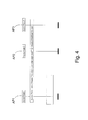
- illustrates as a signaling chart a method according to a second advantageous embodiment of the invention in which the method is implemented on the wireless access network,
- Fig. 5
- illustrates as a signaling chart a method according to a second advantageous embodiment of the invention in which the method is implemented on the wired access network, and
- Fig. 6
- shows the coupling of and data transmission between two nodes in different functional layers of a protocol stack.
- Fig. 7
- shows an access point according to an advantageous embodiment of the invention in a reduced block chart.
- In the following, the invention will be described by using the WLAN as an example of the wireless access network and the Ethernet as an example of the wired access network, but it is obvious that the present invention can also be applied in connection with other communication systems, in which both wired access network(s) and wireless access network(s) are implemented. Fig. 1 shows an example of a
communication system 1 according to an advantageous embodiment of the present invention. Thecommunication system 1 comprises at least onewireless access network 2 and at least onewired access network 3. It is obvious that there may exist more than one wireless access network and/or more than one wired access network in the communication system in which the present invention can be applied. - The
communication system 1 comprises access points AP1, AP2, AP3 which have transmitting and receiving means for providing communication with wireless clients WC1, WC2 and thewireless access network 2. The wireless client WC1, WC2 can, for example, be a wireless terminal having data processing means, such as a laptop PC, and wireless communication means, such as a radio modem. Some wireless access networks may comprise one or more access point controllers separate from the access points. The function of the access point controllers is to control the operation of the access points. The communication between the wireless clients and the rest of the communication system is routed via the access point controller(s). However, in Fig. 1 all the access points AP1, AP2, AP3 and (possible) access point controllers are shown as single units. The access points AP1, AP2, AP3 are directly connected to the wired network in thecommunication system 1 of Fig. 1, wherein all the access points AP1, AP2, AP3 can directly communicate with other access points and other devices connected to thewired access network 3. - A radio connection is arranged between the access point AP1, AP2 and the wireless clients WC1, WC2 for transmitting e.g. signals required for setting up a connection and, during the connection, information, such as data packets of an Internet application.
- The
wired access network 3 comprises one or more servers S, one or more routers R and it may also comprise one or more wired clients C. The server S controls the operation of thewired access network 3, and it can communicate with other devices connected to thewired access network 3. The router R is implemented insuch communication systems 1 in which communication with other networks e.g. Internet is necessary. The router R routes data packets from the wired and wireless access network to other networks and, respectively, receives packets from other networks and retransmits the received packets to the intended receiver, or to another router. - In the Internet data network, a TCP/IP protocol stack is generally used, which can be divided into five functional layers. These five layers are, listed from bottom to top: the physical layer (Layer 1), the link layer (Layer 2), the network layer (Layer 3), the transport layer (Layer 4), and the application layer (Layer 5). All the nodes of the Internet data network contain at least the first three layers. Of these nodes, routers, which are primarily responsible for the couplings of the data network, do not need the transport and application layers. However, hosts, between which the actual data transmission connection is set up, contain all the said five layers. Even though all the upper level layers use the services of the underlying layer for data transmission, logically the corresponding layers of the hosts communicate with each other by using the protocol typical for the layer.
- In the following, the meaning of these different protocol stack layers will be described briefly. The actual data transmission is conducted in the physical layer by using a data transmission means, such as a wireless radio network or landline cabling.
- The link layer attends to solutions required by different network technologies, wherein the upper level layers do not have to know how the data transmission network used at a given time is constructed. The link layer processes different addressing and frame modes and is responsible for the data transmission between two terminals in the same communication network.
- The task of the network layer is to route packets between terminals in the communication network. The network layer provides the coupling between different data networks, wherein the upper level layers do not have to know about the structure of the data network. On this network layer level, for instance protocols IP (Internet Protocol), ICMP (Internet Control Message Protocol) and IGMP (Internet Group Management Protocol) are used.
- The transport layer provides a generic end-to-end data transmission connection for the application layer. The application layer uses for instance a TCP protocol (Transmission Control Protocol) and a UDP protocol (User Datagram Protocol).
- The application layer protocols operate above the transport layer and provide application-specific services, such as file transfer services or access network remote login services.
- The application layer protocols operate above the transport layer and provide application-specific services, such as file transfer services or access network remote login services. In the example of Fig. 6, applications running on the application layer in the wireless client WC1 and in the wired host S communicate with each other via the access point AP1. In the communication a so-called HTTP protocol (HyperText Transfer Protocol) is used in the application layer. HTTP protocol is generally used in the Internet data network for loading and presenting the data contained in so-called home pages in the display device of a computer. Other application layer protocols are, for example, Telnet, the file transfer protocol FTP and the simple mail transfer protocol SMTP.
- In the Internet data network, each client or host has its own identifying IP address. The IP address is in the Internet protocol version IPv4 a 32 bit, i.e. 4 byte number which is split into an organization-specific network address and a network-specific device address. In a newer Internet protocol version IPv6, the length of the address fields is increased to 128 bits, which, in practice, means that it is possible to allocate an individual address for all the devices which are connected to the Internet data network. An Internet host connected to the Internet data network via a
access network - The Internet protocol IP specifies the data transmission in packets ("Datagrams"). When a host or a router receives a packet on the IP level, either from the data network or from an upper level of the protocol stack, the first step is to examine whether the packet is intended precisely for the router or client in question. If the packet is intended precisely for this router or client, the packet is transferred from the network layer to the upper layer in this node. If the packet is intended to another node, a so-called routing algorithm is executed in the network layer for concluding how the packet should be processed. First, it is examined whether the packet is intended for another node in the same network. If this is the case, the node can transmit the packet to the destination address by using the mechanisms of the link layer. Thus, the IP address of the network layer level is connected to the corresponding link layer address by using the so-called address resolution protocol ARP. In this node, the packet is also framed into a packet corresponding to the link layer and transmitted further.
- If the packet is intended for another network, the routing algorithm runs through a routing table in order to find out to which address the packet should be transmitted. The routing table typically contains a so-called default address, to which all such packets are transmitted whose routing address cannot be found in the routing table.
- The transmission of IP packets between different coupled data networks on the network layer level is conducted on the basis of IP addresses. In addition to the IP addresses, the devices connected to the Internet data network also have a so-called link layer address, which is also called a device address. Because terminals use link layer services in packet transmission with terminals connected to the same data network, the terminals need the address resolution protocol ARP for connecting the IP addresses to the corresponding link layer addresses. The reverse address resolution protocol RARP connects the link layer addresses to the corresponding IP addresses. The function of the address resolution protocol ARP depends on the structure of the data transmission connection used at a given time.
- In such link layer level protocols which make a simultaneous connection possible between several different clients, i.e. so-called "Broadcast" connections, such as the Ethernet, the address resolution program typically uses four different messages: an ARP request, an ARP reply, an RARP request, and an RARP reply.
- In the following, the method according to a first advantageous embodiment of the present invention will be described with reference to the signaling diagrams of Figs. 2 and 3. When a requesting node, such as some of the access points AP1, AP2, AP3, needs to find out whether a target node resides on the
wireless access network 2 or on thewired access network 3, a resolution request message is formed in the requesting node and transmitted to thewired access network 3. If the requesting node is an access point AP1, AP2, AP3, it transmits the message over the wired network interface NIC2 of the access point AP1, AP2, AP3 (Fig. 7) to thewired access network 3. The requesting node also starts a controlling timer T (Fig. 7). The resolution request message can be transmitted as a unicast message addressed directly to the link-layer address of the target node wherein the message comprises the link-layer address of the target node. The target node is one of the access points AP1, AP2, AP3 of thewireless access network 2, or one of the wired nodes S, R of thewired access network 3. The resolution request message may also be transmitted as a multicast message wherein it comprises a special multicast address. It is also possible to use broadcast transmission wherein the resolution request message is marked as a broadcast message wherein all nodes of thewired access network 3 receive and process the message. - In a situation in which the method of the present invention is implemented in the target node and the target node is connected to the
wired access network 3, the following steps are advantageously performed. When the target node AP1, AP2, AP3, S, R receives the resolution request message which is either addressed to it or is a broadcast message, the target node examines the contents of the message. The message comprises identification information of the target node. The identification information is usually the address of the target node. The target node S, R examines whether the identification information of the message equals the identification information of the target node, and if it does the target node will form a resolution reply message. The target node will then transmit the resolution reply message preferably as a unicast message to the requesting node. - The steps of the method of the present invention are advantageously implemented mainly on the link-layer level procedures of the protocol stack of the nodes. The lower level layers of the protocol stack perform necessary steps to forward the messages between physical layer and the link-layer of the protocol stack.
- It is also possible that the target node cannot support the resolution request message according to the invention. In that case there may be a proxy connected in the wired access network which can handle the resolution request message. The proxy then examines if it has information of the target node. If the proxy finds such an information it will form a resolution reply message and transmit it to the requesting device.
- When the requesting node receives the resolution reply message, it examines the address of the sender or some other information of the message to find out to which resolution request message the reply was transmitted. The requesting node can then determine that the target node in question is connected to the
wired access network 3. The requesting node may store the resolution information of the target node into memory means MEM (e.g. cache) so that it is not necessary to send the resolution request message every time the requesting node needs to find out on whichaccess network access network - If the target node is not in the
wired access network 3, the target node does not receive the resolution request message. Neither does any proxy of thewired access network 3 have information of the target node. In that kind of situation the resolution reply message is not transmitted in thewired access network 3, wherein the requesting node will not receive the resolution reply message as is shown in Fig. 3. The requesting node may schedule a retransmission timer for the resolution request so that the resolution request message is retransmitted a couple of times if no response has been received. According to the first advantageous embodiment of the present invention the requesting node determines that the target node in question does not belong to thewired access network 3, if the requesting node does not receive a resolution reply message within a certain time period. - The requesting node can perform the above described checking procedure for more than one target node and save the resolution information of each checked target node.
- For IPv4 networks the Reverse Address Resolution Protocol (RARP) can be used in the method according to the first advantageous embodiment of the present invention. The requesting node can send a RARP request message as the resolution request message in order to resolve whether a target node is on the wired access network. Target nodes which are on the
wired access network 3 can then reply with a RARP reply message, or if the replying node is a proxy on behalf of the target node, a proxy RARP reply message can be used. If RARP is used, the access points must not forward the resolution request messages over the wireless access network. - In the following, the method according to a second advantageous embodiment of the present invention will be described with reference to the signaling diagrams of Figs. 4 and 5 and the protocol stacks of Fig. 6. When a requesting node such as some of the wired nodes S, R or access points AP1, AP2, AP3 needs to find out whether a target node resides on the
wireless access network 2 or on thewired access network 3, a resolution request message is formed e.g. in the link-layer of the requesting node. Then, the requesting node transmits the resolution request message to thewired access network 3. If the requesting node is an access point AP1, AP2, AP3, it transmits the message over the wired network interface NIC2 of the access point AP1, AP2, AP3 to thewired access network 3. This resolution request message can be transmitted as a unicast message addressed directly to the link-layer address of the target node wherein the message comprises the link-layer address of the target node. The target node is one of the access points AP1, AP2, AP3 of thewireless access network 2, or one of the wired nodes S, R of thewired access network 3. The resolution request message may also be transmitted as a multicast message wherein it comprises a special multicast address. It is also possible to use broadcast transmission wherein the resolution request message is marked as a broadcast message. - The access points AP1, AP2, AP3 of the wireless access network need to maintain information of wireless clients which are associated with the access point AP1, AP2, AP3. When an access point AP1, AP2, AP3 receives the resolution request message which is either addressed to it or is a broadcast message, the message is transferred to the link-layer of the protocol stack of the access point AP1, AP2, AP3. Then the link-layer level procedures of the access point AP1, AP2, AP3 examine the contents of the message. The message comprises identification information of the target node. In the access point AP1, AP2, AP3 it is examined if the message has information of the target node. In other words, in the access point AP1, AP2, AP3 it is examined which wireless clients are connected with the access point AP1, AP2, AP3. If the identification information of the message indicates that the target node is a wireless client connected to the access point, a resolution reply message is formed in the access point AP1, AP2, AP3 and transmitted to the requesting node over the wired network interface of the access point.
- When the requesting node receives the resolution reply message, message is transferred to the link-layer of the protocol stack of the requesting node. Then the link-layer level procedures of the requesting node examine the address of the sender or some other information of the message to find out to which resolution request message the reply was transmitted. The requesting node can then determine that the target node in question is connected to the
wireless access network 2. The requesting node may save the resolution information of the target node so that it is not necessary to send the resolution request message every time the requesting node needs to find out on whichaccess network access network - If the target node is not in the
wireless access network 2, no access point has identification information similar to the identification information of the resolution request message. Therefore the resolution reply message is not formed and transmitted in thewired access network 3 and the requesting node will not receive the resolution reply message as is shown in Fig. 5. The requesting node may schedule a retransmission timer for the resolution request so that the resolution request message is retransmitted a couple of times if no response has been received. According to the second advantageous embodiment of the present invention the requesting node determines that the target node in question does not belong to thewireless access network 2, if the requesting node does not receive a resolution reply message within a certain time period. - The requesting node can perform the above described check for more than one target node and save the resolution information of each checked target node.
- The requesting node can use the resolution information for different purposes. For example, there may exist situations in which transmission of information should be restricted only to devices of the
wired access network 3. When a node of the wired access network receives a packet which should be forwarded to a client, the node first examines the resolution information of the client. If the resolution information indicates that the client is connected to a part of the network where the packet is not allowed to be forwarded, the node will not forward the packet to the client. Otherwise the packet will be forwarded normally. In an other example situation the direct transmission between clients of the wireless access network can be prevented by examining at the access point the resolution information prior to packets from one client are forwarded to another client. - It is also possible that the resolution reply message is transmitted independent of whether the target node is a wireless client or a wired client. This is possible, for example, in a
communication system 1 in which the access point AP1, AP2, AP3 transmits the resolution reply message if the target node is a wireless client, and the target node or proxy transmits the resolution reply message if the target node is a wired client. Therefore the requesting device can determine from the sender of the resolution reply message whether the target node is a wireless client or a wired client. - The appended Fig. 7 presents in a reduced manner the features of the access point AP1, AP2, AP3 which are meaningful when implementing the present invention. The hardware part includes, for instance, a microprocessor µP, memory means MEM, a connection logic I/O, and retransmission timer T.
- The network interface architecture comprises a wireless network interface NIC1 and a wired
network interface NIC 2, by means of which the actual physical data transmission connection is established. The practical implementation of these network interfaces depends, for instance, on the type of the network interface in question. For example, a network interface card intended for a wireless access network comprises a radio modem, or the like, whereby it is possible to set up a wireless data transmission connection to the radio modem of the access network. Thus, the network interfaces NIC1, NIC2 constitute said physical layer and can also contain features of the link layer. - It is obvious that the present invention is not limited solely to the above-presented embodiments, but it can be modified within the scope of the appended claims.
Claims (37)
Applications Claiming Priority (2)
| Application Number | Priority Date | Filing Date | Title |
|---|---|---|---|
| US876480 | 2001-06-07 | ||
| US09/876,480 US7085808B2 (en) | 2001-06-07 | 2001-06-07 | Method for distinguishing clients in a communication system, a communication system; and a communication device |
Publications (3)
| Publication Number | Publication Date |
|---|---|
| EP1265420A2 true EP1265420A2 (en) | 2002-12-11 |
| EP1265420A3 EP1265420A3 (en) | 2003-07-02 |
| EP1265420B1 EP1265420B1 (en) | 2006-02-01 |
Family
ID=25367811
Family Applications (1)
| Application Number | Title | Priority Date | Filing Date |
|---|---|---|---|
| EP02396076A Expired - Lifetime EP1265420B1 (en) | 2001-06-07 | 2002-05-28 | A method for distinguishing clients in a communication system, a communication system, and a communication device |
Country Status (6)
| Country | Link |
|---|---|
| US (1) | US7085808B2 (en) |
| EP (1) | EP1265420B1 (en) |
| CN (1) | CN1270494C (en) |
| AT (1) | ATE317195T1 (en) |
| DE (1) | DE60208990T2 (en) |
| ES (1) | ES2256432T3 (en) |
Cited By (6)
| Publication number | Priority date | Publication date | Assignee | Title |
|---|---|---|---|---|
| EP1489801A1 (en) * | 2003-06-19 | 2004-12-22 | Samsung Electronics Co., Ltd. | A hybrid network controller |
| WO2005101802A1 (en) * | 2004-04-14 | 2005-10-27 | Nortel Networks Limited | Mobile terminal with wired and wireless network interfaces |
| WO2006105737A1 (en) * | 2005-04-07 | 2006-10-12 | Huawei Technologies Co., Ltd. | An integrative access system of wireless and wired network |
| CN100396041C (en) * | 2005-09-01 | 2008-06-18 | 华为技术有限公司 | Wireless and wired integrated access network communication system |
| US8272037B2 (en) | 2003-03-14 | 2012-09-18 | Thomson Licensing | Flexible WLAN access point architecture capable of accommodating different user devices |
| WO2020161527A3 (en) * | 2019-02-10 | 2021-05-06 | احمد محمد سيد | Wireless wired exchange |
Families Citing this family (11)
| Publication number | Priority date | Publication date | Assignee | Title |
|---|---|---|---|---|
| US7370098B2 (en) * | 2003-08-06 | 2008-05-06 | International Business Machines Corporation | Autonomic management of autonomic systems |
| US20050097199A1 (en) * | 2003-10-10 | 2005-05-05 | Keith Woodard | Method and system for scanning network devices |
| US7424007B2 (en) * | 2004-05-12 | 2008-09-09 | Cisco Technology, Inc. | Power-save method for 802.11 multicast paging applications |
| US7690002B2 (en) * | 2005-10-11 | 2010-03-30 | Hewlett-Packard Development Company, L.P. | System, method, and computer program product for system event notification and tracking |
| US8606939B1 (en) * | 2005-11-14 | 2013-12-10 | Cisco Technology, Inc. | Method of configuring an on-demand secure connection between a control site and a client network |
| CN1852080B (en) * | 2005-11-30 | 2010-04-14 | 华为技术有限公司 | Method for treating abnormal multicast business |
| US8316427B2 (en) * | 2007-03-09 | 2012-11-20 | International Business Machines Corporation | Enhanced personal firewall for dynamic computing environments |
| US8695081B2 (en) * | 2007-04-10 | 2014-04-08 | International Business Machines Corporation | Method to apply network encryption to firewall decisions |
| DE102009041821A1 (en) * | 2009-09-18 | 2011-03-24 | Phoenix Contact Gmbh & Co. Kg | network |
| JP6759011B2 (en) * | 2016-09-02 | 2020-09-23 | キヤノン株式会社 | Communication equipment, communication methods, and programs |
| CN107517533B (en) * | 2017-08-11 | 2019-10-29 | 四川华体照明科技股份有限公司 | A kind of self-adapting type street lamp loop ownership rapid detection system and method based on NB-IoT |
Citations (1)
| Publication number | Priority date | Publication date | Assignee | Title |
|---|---|---|---|---|
| US5526489A (en) * | 1993-03-19 | 1996-06-11 | 3Com Corporation | System for reverse address resolution for remote network device independent of its physical address |
Family Cites Families (5)
| Publication number | Priority date | Publication date | Assignee | Title |
|---|---|---|---|---|
| JP2980024B2 (en) * | 1996-03-28 | 1999-11-22 | 日本電気株式会社 | Communication method |
| US6304564B1 (en) * | 1996-11-29 | 2001-10-16 | Lucent Technologies Inc. | Method for transmitting messages in wireless communication system using a server process |
| US6487557B1 (en) * | 1997-12-26 | 2002-11-26 | Casio Computer Co., Ltd. | Network-access management system and method applied to network and computer program product including computer program recorded on storage medium for creating display data |
| US6654607B1 (en) * | 2000-02-14 | 2003-11-25 | Toshiba America Research, Inc. | Method and apparatus for enabling and monitoring mobile communication across platforms |
| US6944760B2 (en) * | 2001-05-24 | 2005-09-13 | Openwave Systems Inc. | Method and apparatus for protecting identities of mobile devices on a wireless network |
-
2001
- 2001-06-07 US US09/876,480 patent/US7085808B2/en not_active Expired - Lifetime
-
2002
- 2002-05-28 DE DE60208990T patent/DE60208990T2/en not_active Expired - Lifetime
- 2002-05-28 ES ES02396076T patent/ES2256432T3/en not_active Expired - Lifetime
- 2002-05-28 EP EP02396076A patent/EP1265420B1/en not_active Expired - Lifetime
- 2002-05-28 AT AT02396076T patent/ATE317195T1/en not_active IP Right Cessation
- 2002-06-07 CN CNB02122854XA patent/CN1270494C/en not_active Expired - Fee Related
Patent Citations (1)
| Publication number | Priority date | Publication date | Assignee | Title |
|---|---|---|---|---|
| US5526489A (en) * | 1993-03-19 | 1996-06-11 | 3Com Corporation | System for reverse address resolution for remote network device independent of its physical address |
Non-Patent Citations (2)
| Title |
|---|
| FOX A ET AL: "ADAPTING TO NETWORK AND CLIENT VARIABILITY VIA ON-DEMAND DYNAMIC DISTILLATION" ACM SIGPLAN NOTICES, ASSOCIATION FOR COMPUTING MACHINERY, NEW YORK, US, vol. 31, no. 9, 1 September 1996 (1996-09-01), pages 160-170, XP000639230 ISSN: 0362-1340 * |
| HAN R ET AL: "DYNAMIC ADAPTATION IN AN IMAGE TRANSCODING PROXY FOR MOBILE WEB BROWSING" IEEE PERSONAL COMMUNICATIONS, IEEE COMMUNICATIONS SOCIETY, US, vol. 5, no. 6, 1 December 1998 (1998-12-01), pages 8-17, XP000790121 ISSN: 1070-9916 * |
Cited By (9)
| Publication number | Priority date | Publication date | Assignee | Title |
|---|---|---|---|---|
| US8272037B2 (en) | 2003-03-14 | 2012-09-18 | Thomson Licensing | Flexible WLAN access point architecture capable of accommodating different user devices |
| EP1489801A1 (en) * | 2003-06-19 | 2004-12-22 | Samsung Electronics Co., Ltd. | A hybrid network controller |
| US8406227B2 (en) | 2003-06-19 | 2013-03-26 | Samsung Electronics Co., Ltd. | Hybrid wired and wireless communication system and a communication method thereof |
| WO2005101802A1 (en) * | 2004-04-14 | 2005-10-27 | Nortel Networks Limited | Mobile terminal with wired and wireless network interfaces |
| WO2006105737A1 (en) * | 2005-04-07 | 2006-10-12 | Huawei Technologies Co., Ltd. | An integrative access system of wireless and wired network |
| CN100421400C (en) * | 2005-04-07 | 2008-09-24 | 华为技术有限公司 | Integrative access system of wireless and wired network |
| US8208971B2 (en) | 2005-04-07 | 2012-06-26 | Huawei Technologies Co., Ltd. | Integrated access system of wireless and wired network |
| CN100396041C (en) * | 2005-09-01 | 2008-06-18 | 华为技术有限公司 | Wireless and wired integrated access network communication system |
| WO2020161527A3 (en) * | 2019-02-10 | 2021-05-06 | احمد محمد سيد | Wireless wired exchange |
Also Published As
| Publication number | Publication date |
|---|---|
| EP1265420A3 (en) | 2003-07-02 |
| ES2256432T3 (en) | 2006-07-16 |
| US7085808B2 (en) | 2006-08-01 |
| US20020194353A1 (en) | 2002-12-19 |
| DE60208990D1 (en) | 2006-04-13 |
| DE60208990T2 (en) | 2006-07-27 |
| CN1391384A (en) | 2003-01-15 |
| CN1270494C (en) | 2006-08-16 |
| ATE317195T1 (en) | 2006-02-15 |
| EP1265420B1 (en) | 2006-02-01 |
Similar Documents
| Publication | Publication Date | Title |
|---|---|---|
| US7085808B2 (en) | Method for distinguishing clients in a communication system, a communication system; and a communication device | |
| KR100317443B1 (en) | Internet protocol filter | |
| US6128664A (en) | Address-translating connection device | |
| EP0943201B1 (en) | Method for using dhcp to override learned ip addresses in a network | |
| JP4226553B2 (en) | Routing in data communication networks | |
| US6681259B1 (en) | Method for coupling a wireless terminal to a data transmission network and a wireless terminal | |
| Narten et al. | RFC 4861: Neighbor discovery for IP version 6 (IPv6) | |
| US6895443B2 (en) | Method and system for facilitating communication between nodes on different segments of a network | |
| US6049834A (en) | Layer 3 switch unicast protocol | |
| US7567573B2 (en) | Method for automatic traffic interception | |
| US7373407B2 (en) | Communications system for establishing PPP connections between IEEE 1394 terminals and IP networks | |
| JP2000138976A (en) | Mobile tcp and method for setting and maintaining mobile tcp connection | |
| USH2065H1 (en) | Proxy server | |
| US20050044196A1 (en) | Method of and system for host based configuration of network devices | |
| EP1672876A2 (en) | Network system and method for assigning dynamic address and performing routing based upon dynamic address | |
| JP4292897B2 (en) | Relay device and port forward setting method | |
| US20080215754A1 (en) | Bridging Data Network Communications | |
| Cisco | Apple Talk | |
| Racherla et al. | IPv6 Introduction and Configuration | |
| JP2001285370A (en) | Remote access server apparatus and dhcp server apparatus | |
| EP1241859A1 (en) | Method and system for obtaining domain name and IP-address resolution | |
| Narten et al. | RFC1970: Neighbor Discovery for IP version 6 (IPv6) | |
| KR100642056B1 (en) | A layer3 proxy device on the computer network | |
| AU2021390925A1 (en) | Secure data connections in low data rate networks | |
| CN114598619A (en) | Secure data connection in low data rate networks |
Legal Events
| Date | Code | Title | Description |
|---|---|---|---|
| PUAI | Public reference made under article 153(3) epc to a published international application that has entered the european phase |
Free format text: ORIGINAL CODE: 0009012 |
|
| AK | Designated contracting states |
Kind code of ref document: A2 Designated state(s): AT BE CH CY DE DK ES FI FR GB GR IE IT LI LU MC NL PT SE TR |
|
| AX | Request for extension of the european patent |
Free format text: AL;LT;LV;MK;RO;SI |
|
| PUAL | Search report despatched |
Free format text: ORIGINAL CODE: 0009013 |
|
| AK | Designated contracting states |
Designated state(s): AT BE CH CY DE DK ES FI FR GB GR IE IT LI LU MC NL PT SE TR |
|
| AX | Request for extension of the european patent |
Extension state: AL LT LV MK RO SI |
|
| 17P | Request for examination filed |
Effective date: 20031205 |
|
| 17Q | First examination report despatched |
Effective date: 20040116 |
|
| AKX | Designation fees paid |
Designated state(s): AT BE CH CY DE DK ES FI FR GB GR IE IT LI LU MC NL PT SE TR |
|
| GRAP | Despatch of communication of intention to grant a patent |
Free format text: ORIGINAL CODE: EPIDOSNIGR1 |
|
| GRAS | Grant fee paid |
Free format text: ORIGINAL CODE: EPIDOSNIGR3 |
|
| GRAA | (expected) grant |
Free format text: ORIGINAL CODE: 0009210 |
|
| AK | Designated contracting states |
Kind code of ref document: B1 Designated state(s): AT BE CH CY DE DK ES FI FR GB GR IE IT LI LU MC NL PT SE TR |
|
| PG25 | Lapsed in a contracting state [announced via postgrant information from national office to epo] |
Ref country code: FI Free format text: LAPSE BECAUSE OF FAILURE TO SUBMIT A TRANSLATION OF THE DESCRIPTION OR TO PAY THE FEE WITHIN THE PRESCRIBED TIME-LIMIT Effective date: 20060201 Ref country code: LI Free format text: LAPSE BECAUSE OF FAILURE TO SUBMIT A TRANSLATION OF THE DESCRIPTION OR TO PAY THE FEE WITHIN THE PRESCRIBED TIME-LIMIT Effective date: 20060201 Ref country code: NL Free format text: LAPSE BECAUSE OF FAILURE TO SUBMIT A TRANSLATION OF THE DESCRIPTION OR TO PAY THE FEE WITHIN THE PRESCRIBED TIME-LIMIT Effective date: 20060201 Ref country code: AT Free format text: LAPSE BECAUSE OF FAILURE TO SUBMIT A TRANSLATION OF THE DESCRIPTION OR TO PAY THE FEE WITHIN THE PRESCRIBED TIME-LIMIT Effective date: 20060201 Ref country code: BE Free format text: LAPSE BECAUSE OF FAILURE TO SUBMIT A TRANSLATION OF THE DESCRIPTION OR TO PAY THE FEE WITHIN THE PRESCRIBED TIME-LIMIT Effective date: 20060201 Ref country code: CH Free format text: LAPSE BECAUSE OF FAILURE TO SUBMIT A TRANSLATION OF THE DESCRIPTION OR TO PAY THE FEE WITHIN THE PRESCRIBED TIME-LIMIT Effective date: 20060201 |
|
| REG | Reference to a national code |
Ref country code: GB Ref legal event code: FG4D |
|
| REG | Reference to a national code |
Ref country code: CH Ref legal event code: EP |
|
| REG | Reference to a national code |
Ref country code: IE Ref legal event code: FG4D |
|
| REF | Corresponds to: |
Ref document number: 60208990 Country of ref document: DE Date of ref document: 20060413 Kind code of ref document: P |
|
| PG25 | Lapsed in a contracting state [announced via postgrant information from national office to epo] |
Ref country code: DK Free format text: LAPSE BECAUSE OF FAILURE TO SUBMIT A TRANSLATION OF THE DESCRIPTION OR TO PAY THE FEE WITHIN THE PRESCRIBED TIME-LIMIT Effective date: 20060501 Ref country code: SE Free format text: LAPSE BECAUSE OF FAILURE TO SUBMIT A TRANSLATION OF THE DESCRIPTION OR TO PAY THE FEE WITHIN THE PRESCRIBED TIME-LIMIT Effective date: 20060501 |
|
| PG25 | Lapsed in a contracting state [announced via postgrant information from national office to epo] |
Ref country code: IE Free format text: LAPSE BECAUSE OF NON-PAYMENT OF DUE FEES Effective date: 20060529 |
|
| PG25 | Lapsed in a contracting state [announced via postgrant information from national office to epo] |
Ref country code: MC Free format text: LAPSE BECAUSE OF NON-PAYMENT OF DUE FEES Effective date: 20060531 |
|
| NLV1 | Nl: lapsed or annulled due to failure to fulfill the requirements of art. 29p and 29m of the patents act | ||
| PG25 | Lapsed in a contracting state [announced via postgrant information from national office to epo] |
Ref country code: PT Free format text: LAPSE BECAUSE OF FAILURE TO SUBMIT A TRANSLATION OF THE DESCRIPTION OR TO PAY THE FEE WITHIN THE PRESCRIBED TIME-LIMIT Effective date: 20060703 |
|
| REG | Reference to a national code |
Ref country code: ES Ref legal event code: FG2A Ref document number: 2256432 Country of ref document: ES Kind code of ref document: T3 |
|
| REG | Reference to a national code |
Ref country code: CH Ref legal event code: PL |
|
| ET | Fr: translation filed | ||
| PLBE | No opposition filed within time limit |
Free format text: ORIGINAL CODE: 0009261 |
|
| STAA | Information on the status of an ep patent application or granted ep patent |
Free format text: STATUS: NO OPPOSITION FILED WITHIN TIME LIMIT |
|
| 26N | No opposition filed |
Effective date: 20061103 |
|
| PG25 | Lapsed in a contracting state [announced via postgrant information from national office to epo] |
Ref country code: GR Free format text: LAPSE BECAUSE OF FAILURE TO SUBMIT A TRANSLATION OF THE DESCRIPTION OR TO PAY THE FEE WITHIN THE PRESCRIBED TIME-LIMIT Effective date: 20060502 |
|
| PG25 | Lapsed in a contracting state [announced via postgrant information from national office to epo] |
Ref country code: LU Free format text: LAPSE BECAUSE OF NON-PAYMENT OF DUE FEES Effective date: 20060528 Ref country code: TR Free format text: LAPSE BECAUSE OF FAILURE TO SUBMIT A TRANSLATION OF THE DESCRIPTION OR TO PAY THE FEE WITHIN THE PRESCRIBED TIME-LIMIT Effective date: 20060201 |
|
| PG25 | Lapsed in a contracting state [announced via postgrant information from national office to epo] |
Ref country code: CY Free format text: LAPSE BECAUSE OF FAILURE TO SUBMIT A TRANSLATION OF THE DESCRIPTION OR TO PAY THE FEE WITHIN THE PRESCRIBED TIME-LIMIT Effective date: 20060201 |
|
| REG | Reference to a national code |
Ref country code: DE Ref legal event code: R082 Ref document number: 60208990 Country of ref document: DE Representative=s name: ZACCO DR. PETERS UND PARTNER, DE |
|
| REG | Reference to a national code |
Ref country code: GB Ref legal event code: 732E Free format text: REGISTERED BETWEEN 20121004 AND 20121010 |
|
| REG | Reference to a national code |
Ref country code: DE Ref legal event code: R081 Ref document number: 60208990 Country of ref document: DE Owner name: VRINGO INFRASTRUCTURE INC., US Free format text: FORMER OWNER: NOKIA CORP., ESPOO, FI Effective date: 20121023 Ref country code: DE Ref legal event code: R082 Ref document number: 60208990 Country of ref document: DE Representative=s name: ZACCO DR. PETERS UND PARTNER, DE Effective date: 20121023 Ref country code: DE Ref legal event code: R081 Ref document number: 60208990 Country of ref document: DE Owner name: VRINGO INFRASTRUCTURE INC., NEW YORK, US Free format text: FORMER OWNER: NOKIA CORP., 02610 ESPOO, FI Effective date: 20121023 Ref country code: DE Ref legal event code: R082 Ref document number: 60208990 Country of ref document: DE Representative=s name: ZACCO PATENTANWALTS- UND RECHTSANWALTSGESELLSC, DE Effective date: 20121023 |
|
| REG | Reference to a national code |
Ref country code: FR Ref legal event code: TP Owner name: VRINGO INFRASTRUCTURE, INC., US Effective date: 20130107 |
|
| REG | Reference to a national code |
Ref country code: ES Ref legal event code: PC2A Owner name: VRINGO INFRASTRUCTURE INC. Effective date: 20130322 |
|
| REG | Reference to a national code |
Ref country code: FR Ref legal event code: PLFP Year of fee payment: 15 |
|
| REG | Reference to a national code |
Ref country code: FR Ref legal event code: PLFP Year of fee payment: 16 |
|
| REG | Reference to a national code |
Ref country code: FR Ref legal event code: PLFP Year of fee payment: 17 |
|
| PGFP | Annual fee paid to national office [announced via postgrant information from national office to epo] |
Ref country code: ES Payment date: 20180601 Year of fee payment: 17 |
|
| PGFP | Annual fee paid to national office [announced via postgrant information from national office to epo] |
Ref country code: GB Payment date: 20180523 Year of fee payment: 17 |
|
| PGFP | Annual fee paid to national office [announced via postgrant information from national office to epo] |
Ref country code: IT Payment date: 20190527 Year of fee payment: 18 |
|
| PGFP | Annual fee paid to national office [announced via postgrant information from national office to epo] |
Ref country code: FR Payment date: 20190410 Year of fee payment: 18 |
|
| GBPC | Gb: european patent ceased through non-payment of renewal fee |
Effective date: 20190528 |
|
| PG25 | Lapsed in a contracting state [announced via postgrant information from national office to epo] |
Ref country code: GB Free format text: LAPSE BECAUSE OF NON-PAYMENT OF DUE FEES Effective date: 20190528 |
|
| REG | Reference to a national code |
Ref country code: ES Ref legal event code: FD2A Effective date: 20200928 |
|
| PG25 | Lapsed in a contracting state [announced via postgrant information from national office to epo] |
Ref country code: ES Free format text: LAPSE BECAUSE OF NON-PAYMENT OF DUE FEES Effective date: 20190529 |
|
| PG25 | Lapsed in a contracting state [announced via postgrant information from national office to epo] |
Ref country code: FR Free format text: LAPSE BECAUSE OF NON-PAYMENT OF DUE FEES Effective date: 20200531 |
|
| PGFP | Annual fee paid to national office [announced via postgrant information from national office to epo] |
Ref country code: DE Payment date: 20210505 Year of fee payment: 20 |
|
| PG25 | Lapsed in a contracting state [announced via postgrant information from national office to epo] |
Ref country code: IT Free format text: LAPSE BECAUSE OF NON-PAYMENT OF DUE FEES Effective date: 20200528 |
|
| REG | Reference to a national code |
Ref country code: DE Ref legal event code: R079 Ref document number: 60208990 Country of ref document: DE Free format text: PREVIOUS MAIN CLASS: H04L0029060000 Ipc: H04L0065000000 |
|
| REG | Reference to a national code |
Ref country code: DE Ref legal event code: R082 Ref document number: 60208990 Country of ref document: DE Representative=s name: ZACCO LEGAL RECHTSANWALTSGESELLSCHAFT MBH, DE |
|
| REG | Reference to a national code |
Ref country code: DE Ref legal event code: R071 Ref document number: 60208990 Country of ref document: DE |