EP1255924B1 - An engine management system - Google Patents
An engine management system Download PDFInfo
- Publication number
- EP1255924B1 EP1255924B1 EP01910836A EP01910836A EP1255924B1 EP 1255924 B1 EP1255924 B1 EP 1255924B1 EP 01910836 A EP01910836 A EP 01910836A EP 01910836 A EP01910836 A EP 01910836A EP 1255924 B1 EP1255924 B1 EP 1255924B1
- Authority
- EP
- European Patent Office
- Prior art keywords
- engine
- trim
- map
- control
- palm
- Prior art date
- Legal status (The legal status is an assumption and is not a legal conclusion. Google has not performed a legal analysis and makes no representation as to the accuracy of the status listed.)
- Expired - Lifetime
Links
Images


Classifications
-
- F—MECHANICAL ENGINEERING; LIGHTING; HEATING; WEAPONS; BLASTING
- F02—COMBUSTION ENGINES; HOT-GAS OR COMBUSTION-PRODUCT ENGINE PLANTS
- F02D—CONTROLLING COMBUSTION ENGINES
- F02D41/00—Electrical control of supply of combustible mixture or its constituents
- F02D41/30—Controlling fuel injection
- F02D41/3005—Details not otherwise provided for
-
- F—MECHANICAL ENGINEERING; LIGHTING; HEATING; WEAPONS; BLASTING
- F02—COMBUSTION ENGINES; HOT-GAS OR COMBUSTION-PRODUCT ENGINE PLANTS
- F02D—CONTROLLING COMBUSTION ENGINES
- F02D37/00—Non-electrical conjoint control of two or more functions of engines, not otherwise provided for
- F02D37/02—Non-electrical conjoint control of two or more functions of engines, not otherwise provided for one of the functions being ignition
-
- F—MECHANICAL ENGINEERING; LIGHTING; HEATING; WEAPONS; BLASTING
- F02—COMBUSTION ENGINES; HOT-GAS OR COMBUSTION-PRODUCT ENGINE PLANTS
- F02D—CONTROLLING COMBUSTION ENGINES
- F02D41/00—Electrical control of supply of combustible mixture or its constituents
- F02D41/24—Electrical control of supply of combustible mixture or its constituents characterised by the use of digital means
- F02D41/2406—Electrical control of supply of combustible mixture or its constituents characterised by the use of digital means using essentially read only memories
- F02D41/2409—Addressing techniques specially adapted therefor
- F02D41/2422—Selective use of one or more tables
-
- F—MECHANICAL ENGINEERING; LIGHTING; HEATING; WEAPONS; BLASTING
- F02—COMBUSTION ENGINES; HOT-GAS OR COMBUSTION-PRODUCT ENGINE PLANTS
- F02D—CONTROLLING COMBUSTION ENGINES
- F02D41/00—Electrical control of supply of combustible mixture or its constituents
- F02D41/24—Electrical control of supply of combustible mixture or its constituents characterised by the use of digital means
- F02D41/26—Electrical control of supply of combustible mixture or its constituents characterised by the use of digital means using computer, e.g. microprocessor
- F02D41/263—Electrical control of supply of combustible mixture or its constituents characterised by the use of digital means using computer, e.g. microprocessor the program execution being modifiable by physical parameters
-
- F—MECHANICAL ENGINEERING; LIGHTING; HEATING; WEAPONS; BLASTING
- F02—COMBUSTION ENGINES; HOT-GAS OR COMBUSTION-PRODUCT ENGINE PLANTS
- F02D—CONTROLLING COMBUSTION ENGINES
- F02D2400/00—Control systems adapted for specific engine types; Special features of engine control systems not otherwise provided for; Power supply, connectors or cabling for engine control systems
- F02D2400/11—After-sales modification devices designed to be used to modify an engine afterwards
-
- F—MECHANICAL ENGINEERING; LIGHTING; HEATING; WEAPONS; BLASTING
- F02—COMBUSTION ENGINES; HOT-GAS OR COMBUSTION-PRODUCT ENGINE PLANTS
- F02D—CONTROLLING COMBUSTION ENGINES
- F02D2400/00—Control systems adapted for specific engine types; Special features of engine control systems not otherwise provided for; Power supply, connectors or cabling for engine control systems
- F02D2400/18—Packaging of the electronic circuit in a casing
Landscapes
- Engineering & Computer Science (AREA)
- Chemical & Material Sciences (AREA)
- Combustion & Propulsion (AREA)
- Mechanical Engineering (AREA)
- General Engineering & Computer Science (AREA)
- Microelectronics & Electronic Packaging (AREA)
- Computer Hardware Design (AREA)
- Combined Controls Of Internal Combustion Engines (AREA)
- Electrical Control Of Air Or Fuel Supplied To Internal-Combustion Engine (AREA)
- Testing Of Engines (AREA)
- Control Of Throttle Valves Provided In The Intake System Or In The Exhaust System (AREA)
- Control Of Vehicle Engines Or Engines For Specific Uses (AREA)
- Iron Core Of Rotating Electric Machines (AREA)
- Lifting Devices For Agricultural Implements (AREA)
Abstract
Description
- This application claims the benefit of the earlier filing date of U.S.
Provisional Application 60/183,380, filed 18 February 2000, the disclosure of which is incorporated by reference herein in its entirety. - The present disclosure is directed to an engine management system for an internal combustion engine. In particular, this disclosure is directed to providing a system that allows an operator to transfer engine management data between a palm-size computer and an engine control system, and to transfer engine management files between the palm-size computer and an external computer. As an example, a system according to one embodiment enables an operator to calibrate the engine operation, either while the engine is not running or while operating in its intended environment, by changing trim control values, which represent modifications to base engine control values that are based on an engine control map. More particularly, a recreational vehicle rider can generate trim control maps for calibrating base engine control maps, e.g., such as for ignition timing and fuel delivery, while riding or driving the vehicle.
- It is believed that the performance of an internal combustion engine is dependent on a number of factors including the operating cycle (e.g., two-stroke, four-stroke, Otto, diesel, or Wankel), the number and design of combustion chambers, the selection and control of ignition and fuel delivery systems, and the ambient conditions in which the engine operates.
- Examples of design choices for a combustion chamber are believed to include choosing a compression ratio and choosing the numbers of intake and exhaust valves associated with each chamber. In general, it is believed that these choices cannot be changed so as to calibrate engine operation after the engine has been built.
- With regard to ignition systems, breaker point systems and electronic ignition systems are known. It is believed that these known systems provide spark timing based on an operating characteristic of the engine, e.g., speed of rotation and load. In the case of breaker point systems, it is believed that engine speed is frequently detected mechanically using centrifugally displaced weights, and that intake manifold vacuum is commonly used to detect engine load. In the case of electronic ignition systems, it is believed that engine speed is generally detected with an angular motion sensor associated with rotation of the crankshaft, and that engine load is frequently detected, for example, by the output of a throttle position sensor. In each case, spark timing is believed to be fixed according to these known systems for a given operating state of the engine.
- With regard to fuel delivery systems, carburetors and fuel injection systems are known. It is believed that these known systems supply a quantity of fuel, e.g., gasoline, that is based on the amount of air being admitted to the engine, i.e., in accordance with the position of the throttle as set by the operator. In the case of carburetors, it is believed that fuel is delivered by a system of orifices, known as "jets." As examples of carburetor operation, it is believed that an idle jet may supply fuel downstream of the throttle valve at engine idling speeds, and that fuel delivery may be boosted by an accelerator pump to facilitate rapid increases in engine speed. It is believed that most carburetors must be disassembled and different size jets or pumps installed to modify the amount of fuel delivery. However, this is a laborious process that, it is believed, that most often, can only be done while the engine is not running.
- It is believed that known fuel injection systems, which can be operated electronically, spray a precisely metered amount of fuel into the intake system or directly into the combustion cylinder. The fuel quantity is believed to be determined by a controller based on the state of the engine and a data table known as a "map" or "look-up table." It is believed that the map includes a collection of possible values or "setpoints" for each of at least one independent variable (i.e., a characteristic of the state of the engine), which can be measured by a sensor connected to the controller, and a collection of corresponding control values, for a dependent variable control function, e.g., fuel quantity.
- Conventionally, it is believed that maps are developed by the engine manufacturer and permanently set in an engine control unit at the factory. Currently, for on-road vehicles, this is believed to be legally required in order to meet emissions regulations. However, it is believed that even when it is not legally required, the manufacturers prevent engine operators from modifying the maps for a variety of reasons such as the manufacturers believe that their maps provide the best engine performance, the manufacturers are afraid that an engine operator might damage the engine by specifying inappropriate control values, or the manufacturers assume that an engine operator might not have sufficient skill to properly modify a map. However, it is believed that the manufacturers have "optimized" their maps to perform best under a set of conditions that they specify. In most cases, it is believed that these conditions do not match the conditions in which the engine is operated. Consequently, stock maps are believed to limit, rather than optimize, an engine's performance.
- It is further believed that ambient conditions such as air temperature, altitude, and barometric pressure affect engine performance. It is believed that these conditions generally impact the entire operating range of the engine. In the case of fuel injection, it is believed to be known to compensation for these conditions by calculating an adjustment for every operating state of the engine.
- Thus, engine performance is believed to be substantially dependent on how combustion is accomplished in the ambient conditions. The stoichiometric ratio of air to gasoline is 14.7:1. However, it is believed that ratios from about 10:1 to about 20:1 will combust, and that it is often desirable to adjust the air-fuel ratio to achieve specific engine performance (e.g., a certain level of power output, better fuel economy, or reduced emissions). Similarly, it is also believed to be desirable to adjust ignition timing, commonly measured in degrees of crank rotation before a piston reaches top-dead-center of the compression stroke, to achieve specific engine performance (e.g., lowest fuel consumption or reduced emissions).
- It is believed to be a disadvantage of known ignition timing systems and fuel delivery systems that engine operation is constrained by the fixed controls established by the suppliers of these systems. It is also believed to be a disadvantage that any possible adjustments to these known systems requires a technician to reconfigure one or more of the system components, or to disassemble the system, install substitute components, and reassemble the system. Therefore, it is further believed to be a disadvantage of these known systems that neither the effectiveness nor the sufficiency of these adjustments can be determined while continuously operating the engine in its intended environment: And it is yet further believed to be a disadvantage of these known systems that the effect of these adjustments cannot be directly compared.
- There is believed to be a need to overcome these disadvantages of known ignition and fuel delivery systems.
- DE 196 12 796 A1 discloses an electronic travel companion in the form of a minicomputer such as a palm-size computer, which can be inserted in a recess of a dashboard of a vehicle. The recess provides an interface connecting the travel companion to an on-board communication and control network of the vehicle. The network comprises a central control unit receiving various data from the vehicle wheels and a display in the dashboard via data lines. The central control unit provides the data to logic which processes the data for availability at the interface in the recess. The minicomputer may be used not only for carrying away data collected during operation of the vehicle, but communicate such data as a road map for use in a navigation system of the vehicle and personalized data for adjusting a seating position or securing the car against theft to the communication and control network of the vehicle.
- WO 92/09957 A1 discloses an engine controller comprising an electronic control unit and a remote calibration module. The electronic control unit includes a read-write memory storing base calibration data tables containing fuel and spark information used to control engine operation. The read-write memory further stores an overlay data table in relation to each base calibration data table. The overlay data tables contain fuel and spark modifier information that is directly accessible to and modifiable by an operator through the calibration module. The electronic control unit includes a processor which selects fuel and spark base values from the base calibration data tables dependent on current values of such engine operating characteristics as an air density and an engine speed and also selects fuel and spark modifier values from the overlay data tables dependent on the current values of the engine operating characteristics. Based on the selected fuel and spark base values and modifier values, the processor determines fuel and spark control values.
- The calibration module includes a further processor, ROM memory and a display. It can be operated selectively in a display mode and a calibration mode. In the display mode, current values of various operating characteristics of the engine are displayed. In the calibration mode, the modifier information stored in the fuel and spark overlay data tables can be retrieved and displayed. Using input keys of the calibration module, the operator can modify the displayed modifier information. As the modifications are made, they are communicated to a RAM memory of the electronic control unit for temporary storage therein. Upon completion of the modification process, the operator can elect to save the modifications made, which are then written to electrically erasable ROM memory of the electronic control unit.
- The present invention provides an engine management system having all the features of claim 1. In one embodiment, the engine management system comprises an engine control system calculating an engine operating control value, a palm-size computer transportable relative to the engine control system, and an external computer communicating with the palm-size computer. The engine operating control value is adapted to be supplied to the internal combustion engine to vary engine performance. The palm-size computer has height, width, and thickness dimensions that are no larger than approximately 6 inches by approximately 4 inches by approximately 1 inch. The palm-size computer runs a set of engine management tools that communicate engine management data to the engine control system. The external computer downloads to the palm-size computer engine management tools and engine management files, and uploads from the palm-size computer engine management files.
- The accompanying drawings, which are incorporated herein and constitute part of this specification, include one or more embodiments of the invention, and together with a general description given above and a detailed description given below, serve to disclose principles of the invention in accordance with a best mode contemplated for carrying out the invention.
- Figure 1 is a schematic illustration of an embodiment of a system for calibrating engine operation.
- Figure 2 is a plan view of a dash panel according to a first embodiment.
- Figure 3 is a plan view of a dash panel with a docked palm-size computer according to a second embodiment.
- Figure 4 is a perspective view of the dash panel shown in Figure 3 with the palm-size computer shown in a detached configuration.
- Figure 5 is a flow chart illustrating a method of calibrating engine performance in accordance with an embodiment of an engine management tool for calibrating engine operation.
- As they are used in connection with the present invention, the expressions "trim" or "trimming," "group," "map trim definition," and "map set" have specific meanings. The expressions "trim" and "trimming" refer to changing the value of one or more setpoints. The value of this change, which can be positive or negative, can be a function of the original setpoint or a selected increment. The expression "group" refers to an aggregation or parcel of setpoints that are acted upon in unison by a trimming action. A group can be defined by a "map trim definition." For example, a map trim definition can parcel out an engine control map so as to create a group of setpoints that lie within a selected range(s) of the independent variable(s), e.g., sensed engine operating characteristics. The expression "map set" refers to a single engine control map or to an association of plural related engine control maps. For example, a map set can consist solely of an ignition timing map. Alternatively, a map set can comprise an ignition timing map and a fuel delivery map.
- Referring to Figure 1, an
engine management system 10 includes a library of engine management files in anexternal computer 130. These engine management files can be made available to an engine control system via a palm-size computer 120, and can be used for calibrating engine performance. Theengine management 10 includes anengine control unit 20 that is coupled (e.g., via wires or wirelessly) to one or more input or output devices (e.g., sensors or actuators). Theengine control unit 20 can include a processor that uses coded instructions to act on electrical input signal(s) and to supply electrical output signal(s). According to one embodiment, wires electrically connect theengine control unit 20 with various other components, which will be described in detail below. Thehousing 20a of theengine control unit 20 and the other components can be electrically grounded with respect to a vehicle chassis (not shown), e.g., a motorcycle frame, in a known manner. The electrical connections with respect to theengine control unit 20 can comprise two female sockets (not shown) mounted on thehousing 20a for receiving corresponding right-angle male plugs (not shown) at ends of a wiring loom (not shown). Of course, any number of male plugs and any number of female sockets, in any combination and configuration, may be associated with either thehousing 20a or the wiring loom. - The
engine control unit 20 can be installed beneath an operator's seat (not shown). Theengine control unit 20 can be pivotally mounted to facilitate accessibility to the electrical connections and to anignition coil 30 that can be mounted on the underside of theengine control unit 20. Pivoting the engine control unit also facilitates draining contaminates from abarometric pressure sensor 22 that can be incorporated within thehousing 20a of theengine control unit 20. The functions of theignition coil 30 and thebarometric pressure sensor 22, and their relationship to theengine control unit 20, will be described below in greater detail. Additionally, either or both of theignition coil 30 and thebarometric pressure sensor 22 can be mounted apart from theengine control unit 20. - According to one embodiment, the
engine control unit 20 can provide a single engine operating control value, i.e., for adjusting a single engine control, such as ignition timing. However, according to another embodiment, which is shown in the figures, theengine control unit 20 can provide a plurality of engine operating control values, i.e., for controlling a plurality of engine controls, such as fuel quantity and ignition timing. - The
engine control unit 20 is electrically connected to afuel delivery module 40. Thefuel delivery module 40 can include at least onefuel injector 42 that can be mounted on athrottle body 40a extending from a fluid inlet (not shown) to a fluid outlet (not shown). A butterfly valve (not shown) is positioned in thethrottle body 40a between the inlet and the outlet, and is pivotal about an axis (not shown) between a first configuration preventing fluid flow through thethrottle body 40a and a second configuration permitting fluid flow through thethrottle body 40a. An actuator cam (not shown) is connected to the butterfly valve for pivoting the butterfly valve, against the bias of a return spring, e.g., a torsion spring (not shown), from the first configuration to the second configuration. The actuator cam can be connected, via a throttle cable (not shown), to a throttle control element (not shown), which can be operator controlled. As will be discussed in greater detail below, athrottle position sensor 44 is also connected to the butterfly valve for measuring the angular position of the butterfly valve as it is pivoted about the axis. - The fuel injector(s) 42 can be oriented so as to spray a precisely metered amount of fuel from inside the
throttle body 40a toward an intake port (not shown) in a two-stroke engine or through a poppet valve opening (not shown) in a four-stroke engine. In the case of four-stroke engine designs having a plurality of intake valves (not shown), each of theinjectors 42 can be oriented so as to spray fuel through a respective valve opening. - The
fuel delivery module 40 may further comprise an intake air-temperature sensor 46 that can be, for example, mounted through the wall of thethrottle body 40a, and upstream from the butterfly valve. The functions of the air-temperature sensor 46 and its relationship to theengine control unit 20, will be described below in greater detail. - The
fuel delivery module 40, in cooperation with theengine control unit 20, provides a number of advantages including the ability to be adjusted electronically without being removed, disassembled, reassembled, and reinstalled. Another advantage is the ability to be electronically adjusted while the engine is running. Another advantage is the ability to provide separate control of different groups of setpoints that are specified by map trim definitions, which will be described below in greater detail. Yet another advantage is that the fuel injector(s) 42 can be programmed to compensate for changes in ambient conditions, e.g., changes in barometric pressure or air-temperature. According to embodiments of theengine management system 10, it is possible to compensate for variations in the voltage available to actuate the fuel injector(s) 42, and with a lambda sensor, to also compensate for wear and aging of the fuel injector(s) 42. - An electrically operated
fuel pump 50 having a lowpressure fuel inlet 52 receiving fuel from afuel tank 60 and a high-pressure fuel outlet 54 can deliver pressurized fuel to the fuel injector(s) 42. Thefuel pump 50, which can be electrically interconnected with theengine control unit 20, can be a positive displacement type pump or a dynamic type pump. Apressure regulator 70 can be connected to the high-pressure fuel outlet 54 for regulating the pressure of the fuel supplied to the fuel injector(s) 42. Thepressure regulator 70 can relieve excess pressure by returning a portion of the high-pressure fuel stream to thefuel tank 60. Thefuel pump 50 can be mounted wherever space permits, e.g., on the exterior of anengine 100. - A fuel filter (not shown), which can be serviceable, can be a separate unit located at any position along the fuel supply, or the fuel filter can be incorporated within the
fuel tank 60,fuel pump 50, fuel injector(s) 42, orpressure regulator 70. - Referring additionally to Figures 2-4, the
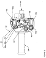
engine control unit 20 is electrically connected to adash panel 80 that is readily accessible to an operator, e.g., the rider in the case of a motorcycle. Thedash panel 80 can comprise at least one switch for regulating a trim signal supplied to theengine control unit 20 and can comprise at least onedisplay device 82 for conveying to the operator information supplied from theengine control unit 20. As shown in Figures 2-4, thedash panel 80 can include a map setselection switch 84, at least one trim +/- adjustment switch 86 (e.g., a trim +pushbutton 86a and a separate trim -pushbutton 86b are shown in Figures 2-4), atrim defeat switch 88, and an on/offswitch 90. Thetrim defeat switch 88 regulates a trim defeat signal that causes theengine control unit 20 to perform two functions. In an "on" position of thetrim defeat switch 88, theengine control unit 20 calculates the engine operating control values equal to the base engine control values as modified by trim control values, and theengine control unit 20 processes the trim signals (as regulated by the at least one trim +/- adjustment switch 86) and the trim defeat signals (as regulated by the trim defeat switch 88). In the "off" position of thetrim defeat switch 88, theengine control unit 20 calculates the engine operating control values equal to only the base engine control, and theengine control unit 20 ignores the trim signals (as regulated by the at least one trim +/-adjustment switch 86) and the trim defeat signals (as regulated by the trim defeat switch 88). The on/offswitch 90 activates or deactivates electricity to all of the components of theapparatus 10 For example, the on/offswitch 90 can disconnect thebattery 34 and the alternator (i.e.,stator 36 and rotor 38) from theengine control unit 20. Thedisplay device 82 can be any analogue or digital device, and can display alpha-numeric characters or graphical images. As shown in Figure 2, thedisplay device 82 can include three "smart" lights S2a, 82b, 82c. The functions of theswitches display device 82 on thedash panel 80, as well as their relationship to theengine control unit 20, will be described below in greater detail. - The
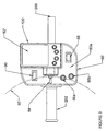
dash panel 80 is mounted with respect to the operator for ergonomic actuation of theswitches display device 82. For example, in the case of a motorcycle, thedash panel 80 can be mounted on thehandlebars 200, e.g., proximate to the left-hand grip 202. Of course, thedash panel 80 could be located at other positions that are readily accessible/visible to the rider in the course of operating the motorcycle. By locating thedash panel 80 as shown in Figures 2-4, theswitches switches Broken line 92 indicates a possible line of travel of the rider's thumb. Moreover, thesmart lights 82a,82b,82c are presented to the rider such that even a quick glance can enable the rider to ascertain whatever information, as specified by the smart light definitions, that is provided by thesmart lights 82a,82b,82c. - Figures 3 and 4 show an alternative arrangement of a dash panel 80'. As best seen in Figure 4, the dash panel 80' can be comprised of a fixed
portion 80a and a relatively transportable palm-size computer 120, which will be described in detail below. The fixedportion 80a, which includes thedisplay device 82, themap selection switch 84, and the on/offswitch 90, is fixed with respect to thehandlebars 200. The palm-size computer 120, which includes a display device, is detachable relative to thehandlebars 200. The display device can be a display screen that is integrated the palm-size computer 120. Although thesmart lights 82a,82b,82c are not shown in Figures 3 and 4, the fixedportion 80a could also include thesmart lights 82a,82b,82c. The palm-size computer 120 can be detached and stowed, either on the operator's person, on the vehicle, or elsewhere, when it is no longer necessary for the rider to trim theengine 100, or when the operator wishes to protect the palm-size computer 120 from the ambient conditions (e.g., rain, dust, etc). - Referring now to all of the figures, the functions and relationships of the system components will now be described. As the
engine management system 10 is shown in the figures, theengine control unit 20 supplies a first control signal for a first engine control, e.g., fuel quantity, and a second control signal for a second engine control, e.g., ignition timing. Thus, for each map set stored in theengine control unit 20, there is an ignition timing map and a fuel amount map. However, in general, a map set can include different numbers of maps (i.e., only one or more than two), different types of maps (e.g., fuel timing, power jet actuation, or power valve actuation), or different combinations of map types (e.g., ignition timing, fuel timing, and power valve actuation). - Table 1 shows an example of a map that includes an arbitrarily selected number of ignition timing setpoints. Each setpoint corresponds to the values of two engine operating characteristics, i.e., an engine speed value and a throttle position setting value. Thus, for a given value of engine speed (e.g., as sensed by or derived from an output signal from a crankshaft angular motion sensor 102) and for a given value of throttle position setting (e.g., as measured by the throttle position sensor 44), an ignition timing setpoint is assigned. For example, this map tells the
engine control unit 20 to deliver an ignition timing of 5 degrees before top dead center (BTDC) at 2000 revolutions per minute (r.p.m.), regardless of throttle opening. At 5000 r.p.m., theengine control unit 20 will vary ignition timing from 25 degrees BTDC, when the throttle is closed, to 30 degrees BTDC, when the throttle is open 75% or more.TABLE 1 Ignition Timing (degrees BTDC) Engine speed (revolutions per minute) 0 2000 5000 7000 Throttle opening (percentage) 0 0 5 25 14 25 0 5 27 12 50 0 5 29 10 75 0 5 30 9 100 0 5 30 7 - In general, a map will include a great number of setpoints that can be assigned for every conceivable engine performance, as determined by measuring one or more engine operating characteristics. If a map includes gaps between specified values of the characteristics (e.g., in Table 1, there are gaps of 2000 r.p.m. or more between the specified values for engine speed), the
engine control unit 20 can interpolate the operating control values between two specified characteristic values. - Engine management data including one or more map sets can be downloaded to the
engine control unit 20 from the palm-size computer 120, either via adata port 110 or by "docking" the palm-size computer 120 with the fixedportion 80a of the dash panel 80'. The coupling between the palm-size computer 120 and either thedata port 110 or the fixedportion 80a can be via wires or wireless. In addition to map sets, the engine management data can include the map trim definitions, and the smart light definitions, as well as software updates for theengine control unit 20. - As it is used herein, the expression "palm-size computer" refers to a hand-held device enclosed within a housing that generally fits within a normal size palm of a normal operator's hand. The height, width, and thickness dimensions of a palm-size computer are no larger than approximately 6 inches by approximately 4 inches by approximately 1 inch. Thus, a palm-size computer is readily transportable, e.g., within a normal size shirt pocket.
- Palm-size computers, which are battery powered, generally include a touch-screen as an input/output device. Examples of such palm-size computers include Hewlett-Packard's Pocket PC and 3Com's PalmPilot.
- The inventors have discovered a number of unexpected results that are achieved by using a palm-
size computer 120 that runs a set of engine management tools for communicating engine management data to the engine control system of a motorcycle. For example, these advantages include the relative small cost of the palm-size computer 120 with respect to the cost of a laptop or desktop personal computer. The reduced size, reduced weight, and increased tolerance to mechanical shock (such as may be caused by impacts, bouncing, jarring, etc.) of the palm-size computer 120 relative to laptop or desktop personal computers, are also advantageous. With regard to the latter, the small size, low weight, and increased tolerance to mechanical shock can even make it possible for a motorcycle rider participating in an endurance event to carry the palm-size computer 120 on-board during the event, e.g., in a clothing pocket or in a storage compartment on the motorcycle. The set of engine management tools can include a calibration tool such as OPT Cal software, which is manufactured by Optimum Power Technology. Using OPT Cal software, the engine operator can tell theengine control unit 20 which map set is to be activated, the map trim definitions that designate the active, i.e., modifiable, portions of the map set, and the smart light definitions. Thedata port 110 used to transfer data between the palm-size computer 120and theengine control unit 20 can be any configuration (e.g., using a physical connection such as a docking or a cable, using transceiving techniques; etc.) and can use any protocol (e.g., RS-232 or ISO 9141). - In addition to processing downloaded data, the
engine control unit 20 can also be connected to any necessary on-board sensor. The air-temperature sensor 46 andbarometric pressure sensor 22 can provide sensor signals representing the density of the air being inducted into theengine 100, and can be used to effect global changes to all control signals based on the values in each map set that has been downloaded to theengine control unit 20. In connection with this invention, the expression "global" refers to making an adjustment with respect to every setpoint in a control map, whereas "local" refers to a setpoint or a group of setpoints in a control map. The sensor signals from theengine speed sensor 102 andthrottle position sensor 44, in addition to being monitored by theengine control unit 20 for accessing setpoints, can be used to determine which setpoint(s) is to be the basis for trimming. Using theengine management system 10 in connection with thefuel delivery system 40 including fuel injector(s) 42 can be considered to be analogous to carburetor jetting, i.e., below a certain throttle opening, trimming according to the present invention corresponds to changing the slow jet, trimming at higher throttle openings corresponds to changing the needle jet, and trimming at still higher throttle openings corresponds to changing the main jet. However, unlike the trims according to theengine management system 10, most jet changes cannot be done while the engine is operating. - Additionally, a sensor (not shown) for electrical system voltage can measure variations that directly affect the reaction time and accuracy of the electromechanical movements within the fuel injector(s) 42. Sensors (not shown) for gear position and side stand deployment can be used to alert a motorcycle rider to potentially harmful or dangerous conditions. And a sensor (not shown) for detecting the initiation of a gear change can signal the
engine control unit 20 to momentarily cut-off the ignition system or thefuel delivery module 40, thereby facilitating smoother shifts. Of course, theengine control unit 20 can be connected to many other sensors, e.g., sensors (not shown) for engine coolant temperature or oil pressure that can provide a warning to the engine operator. - The
engine control unit 20 also receives trim signals, trim defeat signals, and map selection signals from thedash panel 80, and activates thesmart lights 82a,82b,82c as appropriate, in accordance with the smart light definitions. The trim functions are controlled by the map setselection switch 84, the at least one map trim +/-switch 86, and the maptrim defeat switch 88. As it is shown in Figures 2-4, the map setselection switch 84 can be a three-position toggle switch, thereby providing a choice of three map sets. Alternatively, the map setselection switch 84 can provide a choice of only two map sets or more than three map sets. The possible permutations of map sets that can be selected is very large. As a first example, the center position of the map setselection switch 84 can be assigned to a map set that optimizes the acceleration of a vehicle from a resting position, the lower position of the map setselector switch 84 can be assigned to the map set that is to be used a majority of the time, and the upper position of the map setselection switch 84 can be used when peak power output is required. As a second example, the lower position of the map setselector switch 84 can be assigned, in accordance with the accompanying map trim definitions, to enable the ignition timing map to be trimmed, and the upper position of the map set selection switch can be assigned, in accordance with the accompanying map trim definitions, to enable the fuel quantity map to be trimmed. - The map trim +/-
switch 86 can be a three-position rocker switch for incrementing or decrementing the trim control values based on the currently active setpoint (or group of setpoints including the currently active setpoint) by a specified function or amount. Alternatively, rocking the map trim +/-switch 86 to either of the (+) or (-) can initiate a complex set of adjustments to a group of setpoints including the currently active setpoint. As an example of such a complex adjustment, the adjustments to each of the setpoints in the group can be proportional to the adjustment applied to the currently active setpoint. Also, as discussed above, the adjustments signaled by the map trim +/-switch 86 can be applied to the currently selected map, or can be applied to all like maps. As shown in Figures 2-4,separate pushbuttons rocker switch 86. - The map
trim defeat switch 88 allows the engine operator to perform instant comparisons, i.e., "ABAB," between the base map set and the trimmed map set. Moreover, these comparisons can be performed while the engine is being continuously operated in its intended environment. The maptrim defeat switch 88 also signals theengine control unit 20 whether or not to process inputs from the map trim +/-switch 86. - As shown in Figure 2, the
display device 82 can comprise a set of threesmart lights 82a,82b,82c that assist the engine operator in the trimming process. Thesmart lights 82a,82b,82c can be set-up in accordance with the active smart light definitions to convey different information. For example, thesmart lights 82a,82b,82c can indicate if the engine is currently performing in a part of the map that the trims are active, or whether an attempt has been made to trim above or below safe maximum or minimum values that are predetermined by the engine operator. Thesmart lights 82a,82b,82c can also be defined to alert the engine operator to such conditions as a sensor failure, low battery voltage, or engine overheating. In addition to having different modes of operation (i.e., dark, continuously glowing, slow flashing, and rapid flashing), thesmart lights 82a,82b,82c can have different colors (e.g., green, amber, and red) to further increase the amount of information that can be ascertained with only a glance by the operator. - Figure 5 illustrates an example of a
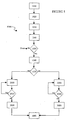
method 1000 for using theengine management system 10 to trim the idle performance of theengine 100 with the object of calibrating a fuel delivery map to obtain optimal idle speed performance. Instep 1010, the maptrim defeat switch 88 is configured to activate the map trim +/-switches step 1020, theengine management system 10 is set-up. The set-up 1020 can include: 1) establishing map trim definitions to designate small throttle settings (e.g., 0-10% throttle opening) as the active range, and to limit trim capability (e.g., no more than +/- 20% of setpoint value in the base control map), 2) establishing smart light definitions so that light 82c glows steadily if thethrottle position sensor 44 supplies a sensor signal indicating that theengine 100 is performing in the active range, and 3) downloading to the engine control unit 20 (e.g., via the data port 110) a map set, the map trim definitions, and the smart light definitions. Instep 1030, theengine 100 is started. Instep 1040, the operator releases throttle so as to allow theengine 100 to idle. Instep 1050, theengine control unit 20 decides, based on the sensor signal supplied from thethrottle position sensor 44, if the engine state is within the active range according to the map trim definitions. If the decision instep 1050 is negative (i.e., "no"), theengine control unit 20 does not supply thedisplay 82 with an information signal to turn-onsmart light 82c. If the decision instep 1050 is positive (i.e., "yes"), theengine control unit 20 supplies to thedisplay 82 an information signal to turn-onsmart light 82c, thereby providing an indication to the operator that manipulating the trim +/-switches trim defeat switch 88 are effective to calibrate theengine 100. Instep 1060, after a positive decision instep 1050, the operator presses the trim +pushbutton 86a. Instep 1070, the operator, with or without assistance from thedisplay 82, decides if the engine performance has varied such that theengine 100 is rotating faster (i.e., an increase in r.p.m.). - In
step 2000, after a positive decision instep 1070, the operator again presses the trim +switch 86a. Instep 2010, the operator again decides if the engine performance has varied such that theengine 100 is rotating faster (i.e., an increase in r.p.m.). If the decision instep 2010 is positive,step 2000 is repeated.Step 2000 is repeated until either the trim capability limit (e.g., a trim signal adding 20% to the base engine control value of the setpoint value according to the base control map) is reached (not shown), or the operator decides that the engine performance has varied such that theengine 100 is rotating slower (i.e., a decrease in r.p.m.). If the decision instep 2010 is negative, the operator presses the trim -pushbutton 86b to return to the previous engine performance. - In
step 3000, after a negative decision instep 1070, the operator presses the trim -pushbutton 86b. Instep 3010, the operator again decides if the engine performance has varied such that theengine 100 is rotating faster (i.e., an increase in r.p.m.). If the decision instep 3010 is positive,step 3000 is repeated until either the trim capability limit (e.g., a trim signal subtracting 20% from the base engine control value of the setpoint value according to the base control map) is reached (not shown), or the operator decides that the engine performance has varied such that theengine 100 is rotating slower (i.e., a decrease in r.p.m.). If the decision instep 3010 is negative, the operator presses the trim +pushbutton 86a to return to the previous engine performance. - In
step 1080, the operator has successfully optimized the idle speed performance of theengine 100, i.e., within the active range according to the map trim definitions. - The map
trim defeat switch 88 can be operated to perform an ABAB comparisons to evaluate the effect of trimming theengine 100 as compared to the base control map. The compilation of the trim control values selected by the operator are stored in the trim control map set and can be uploaded to the personal computer for modifying the base map set, thereby creating a fresh base map that can be used subsequently. - Thus, the
engine management system 10 provides many advantages including calibrating engine performance with adjustments that can be made while theengine 100 is being operated in its intended environment, and enabling an ABAB comparison during this operation to evaluate the effectiveness of the adjustments. An "ABAB" comparison refers to the operator alternately manipulating thetrim defeat switch 88 between its first and second configurations. In the first configuration of thetrim defeat switch 88, a trim defeat signal causes theengine control unit 20 to calculate the engine operating control values equal to the base engine control values modify by the trim control values (i.e., with the trim control map modifying the base control map). In the second configuration of thetrim defeat switch 88, the trim defeat signal causes theengine control unit 20 to calculate the engine operating control values equal solely to the base engine control values (i.e., without the trim control map modifying the base control map). - Additionally, embodiments of the
engine management system 10 can be provided as a kit such that theengine control unit 20 and an ignition module can replace an existing ignition system, and thefuel delivery system 40 andfuel pump 50 can replace an existing carburetor. The kit can additionally include a replacement wiring loom (not shown) to be substituted for the existing wiring loom. Another advantage of theengine management system 10 is that its functions are universally applicable, i.e., theengine management system 10 is not vehicle model specific, and all the main components can be transferred between different vehicles with only an additional loom or a software upgrade to theengine control unit 20 possibly required for the second vehicle. - The embodiments of the
engine management system 10 can be provided for internal combustion engine powered land traversing vehicles, watercraft, and flying vehicles, and thus include motorcycles, all-terrain vehicles, snowmobiles, boats, personal watercraft, and airplanes. - The embodiments described above are examples of the present apparatus and method for trimming an engine management system whereby a number of advantages are achieved.
- These advantages include allowing engine operation to be calibrated during continuous operation in the engine's intended environment. For example, the performance of a race engine can be calibrated during a race, without stopping the engine and without coming into the pits. Moreover, engine performance can be modified within particular user defined ranges of engine performance.
- These advantages also include allowing map set(s) to be provided to the
engine control unit 20 as downloads from the palm-size computer 120. These map sets can be provided to the external processor via any known data transfer technique or protocol, including via the world wide web or by computer diskette. - These advantages further include providing trim controls on the
dash panel 80,80' that are readily accessible to the engine operator in the course of continuously operating theengine 100 in its intended environment. For example, thedash panel 80,80' can comprise at least one switch mounted so as to be readily actuatable by a finger of a hand grasping the left-hand grip 202 ofmotorcycle handlebars 200. The trim control switches can be ergonomically positioned on thedash panel 80,80' to facilitate tactile identification and operation of the controls by a rider wearing gloves. - These advantages yet further include providing one or
more display devices 82 on thedash panel 80,80' that are capable of conveying information with only a brief glance by the engine operator. Thesedisplay devices 82 can include a plurality of "smart," i.e., definable operation,lights 82a,82b,82c that can use different modes (e.g., off, steady glow, slow flashing, rapid flashing, etc.) to present different types of information (e.g., engine status, engine control unit status, trim conditions, etc.). The definitions for operating thesesmart lights 82a,82b,82c can be downloaded to theengine control unit 20 at the same time as the map set(s) are downloaded to theengine control unit 20.
Claims (8)
- An engine management system for an internal combustion engine, the engine management system comprising:an engine control system calculating an engine operating control value, the engine operating control value being adapted to be supplied to the internal combustion engine to vary engine performance;a palm-size computer transportable relative to the engine control system, the palm-size computer running a set of engine management tools for communicating engine management data to the engine control system; andan external computer communicating with the palm-size computer, the external computer downloading to the palm-size computer engine management tools and engine management files and uploading from the palm-size computer engine management files,wherein the downloaded engine management files comprise a base engine control map, the base control map correlating values of an engine performance characteristic with values of a base engine control, and wherein the downloaded engine management data comprises a trim control map separate from the base engine control map, the trim control map correlating the values of the engine performance characteristic with values of a trim control.
- The engine management system according to claim 1, wherein the palm-size computer (120) comprises a touch-screen and a battery.
- The engine management system according to claim 1, wherein the palm-size computer (120) comprises a file sub-system.
- The engine management system according to claim 1, wherein the palm-size computer (120) comprises a touch-screen, a battery, and a file sub-system.
- The engine management system according to claim 1, wherein the palm-size computer (120) comprises a communication sub-system communicating with the external computer (130) via one of a local area network and a world-wide web.
- The engine management system according to claim 5, wherein the communication sub-system includes an internet browser.
- The engine management system according to claim 1, wherein the external computer (130) communicates with the palm-size computer (120) via at least one of a wire, a docking station, and electromagnetic waves.
- The engine management system according to claim 1, wherein the engine management tools comprise a calibration tool that can define all base engine control values in a base engine control map, adjust base engine control values in a base engine control map, communicate a base engine control value to the engine control system, and communicate a base engine control map to the engine control system (20).
Applications Claiming Priority (3)
| Application Number | Priority Date | Filing Date | Title |
|---|---|---|---|
| US18338000P | 2000-02-18 | 2000-02-18 | |
| US183380P | 2000-02-18 | ||
| PCT/US2001/005046 WO2001061176A2 (en) | 2000-02-18 | 2001-02-20 | An engine management system |
Publications (2)
| Publication Number | Publication Date |
|---|---|
| EP1255924A2 EP1255924A2 (en) | 2002-11-13 |
| EP1255924B1 true EP1255924B1 (en) | 2006-05-10 |
Family
ID=22672565
Family Applications (2)
| Application Number | Title | Priority Date | Filing Date |
|---|---|---|---|
| EP01912831A Expired - Lifetime EP1255925B1 (en) | 2000-02-18 | 2001-02-20 | Apparatus and method for calibrating an engine management system |
| EP01910836A Expired - Lifetime EP1255924B1 (en) | 2000-02-18 | 2001-02-20 | An engine management system |
Family Applications Before (1)
| Application Number | Title | Priority Date | Filing Date |
|---|---|---|---|
| EP01912831A Expired - Lifetime EP1255925B1 (en) | 2000-02-18 | 2001-02-20 | Apparatus and method for calibrating an engine management system |
Country Status (10)
| Country | Link |
|---|---|
| US (2) | US6539299B2 (en) |
| EP (2) | EP1255925B1 (en) |
| JP (2) | JP4017398B2 (en) |
| CN (2) | CN1237264C (en) |
| AT (2) | ATE325946T1 (en) |
| AU (4) | AU2001241573B2 (en) |
| CA (2) | CA2398331C (en) |
| DE (2) | DE60119493T2 (en) |
| MX (2) | MXPA02007991A (en) |
| WO (2) | WO2001061176A2 (en) |
Families Citing this family (133)
| Publication number | Priority date | Publication date | Assignee | Title |
|---|---|---|---|---|
| DE19845441C2 (en) * | 1998-10-02 | 2003-01-16 | Ficht Gmbh & Co Kg | Method for electronically trimming an injector |
| US6772061B1 (en) * | 2000-08-18 | 2004-08-03 | Bombardier Recreational Products Inc. | System, method, and apparatus for controlling vehicle performance |
| ATE357680T1 (en) * | 2000-10-07 | 2007-04-15 | David Dickerson | INFORMATION SYSTEM AND METHOD FOR PROVIDING INFORMATION USING A HOLOGRAPHIC ELEMENT |
| US20080161985A1 (en) * | 2001-02-26 | 2008-07-03 | Stefan Hallstensson | Adjusting of the fuel consumption of a water vessel |
| EP1379769A1 (en) * | 2001-04-10 | 2004-01-14 | Robert Bosch Gmbh | SYSTEM AND METHOD FOR CORRECTING THE INJECTION BEHAVIOuR OF AT LEAST ONE INJECTOR |
| WO2002103316A2 (en) | 2001-06-15 | 2002-12-27 | Carcheckup, Llc | Auto diagnosis method and device |
| US6575144B2 (en) * | 2001-07-31 | 2003-06-10 | Ford Motor Company | Method for controlling an engine utilizing vehicle position |
| US20030105577A1 (en) * | 2001-12-05 | 2003-06-05 | Dino Bortolin | Autonomous control of engine operation via a lookup table |
| DE10205375A1 (en) * | 2002-02-09 | 2003-08-21 | Bosch Gmbh Robert | Method and device for controlling an internal combustion engine, in particular for regulating the speed of the internal combustion engine |
| DE10212039A1 (en) * | 2002-03-19 | 2003-10-02 | Zahnradfabrik Friedrichshafen | Wireless communication in vehicles |
| US7280026B2 (en) * | 2002-04-18 | 2007-10-09 | Coldwatt, Inc. | Extended E matrix integrated magnetics (MIM) core |
| US7047128B2 (en) * | 2002-12-12 | 2006-05-16 | Rtk Technologies Limited | Chipped engine control unit system having copy protected and selectable multiple control programs |
| US6925375B2 (en) * | 2003-03-20 | 2005-08-02 | Detroit Diesel Corporation | System and method for determining a parameter set for an engine controller module |
| JP4188227B2 (en) * | 2003-12-26 | 2008-11-26 | 本田技研工業株式会社 | vehicle |
| US7321283B2 (en) * | 2004-08-19 | 2008-01-22 | Coldwatt, Inc. | Vertical winding structures for planar magnetic switched-mode power converters |
| US20060041337A1 (en) * | 2004-08-19 | 2006-02-23 | Augsburger Brett N | Web-enabled engine reprogramming |
| US7427910B2 (en) * | 2004-08-19 | 2008-09-23 | Coldwatt, Inc. | Winding structure for efficient switch-mode power converters |
| DE102004047542A1 (en) | 2004-09-30 | 2006-04-27 | Bayerische Motoren Werke Ag | Device and method for reading out adaptation values from motor vehicle control units |
| WO2006054971A2 (en) * | 2004-11-12 | 2006-05-26 | Volvo Trucks North America, Inc. | Systems and methods for guiding operators to optimized engine operation |
| US7743606B2 (en) * | 2004-11-18 | 2010-06-29 | Honeywell International Inc. | Exhaust catalyst system |
| US7182075B2 (en) * | 2004-12-07 | 2007-02-27 | Honeywell International Inc. | EGR system |
| US7286928B2 (en) * | 2004-12-22 | 2007-10-23 | Caterpillar Inc. | Wireless communications system for work machine components |
| US7165399B2 (en) * | 2004-12-29 | 2007-01-23 | Honeywell International Inc. | Method and system for using a measure of fueling rate in the air side control of an engine |
| US7467614B2 (en) | 2004-12-29 | 2008-12-23 | Honeywell International Inc. | Pedal position and/or pedal change rate for use in control of an engine |
| US7275374B2 (en) * | 2004-12-29 | 2007-10-02 | Honeywell International Inc. | Coordinated multivariable control of fuel and air in engines |
| US7591135B2 (en) * | 2004-12-29 | 2009-09-22 | Honeywell International Inc. | Method and system for using a measure of fueling rate in the air side control of an engine |
| US7328577B2 (en) | 2004-12-29 | 2008-02-12 | Honeywell International Inc. | Multivariable control for an engine |
| US20060168945A1 (en) * | 2005-02-02 | 2006-08-03 | Honeywell International Inc. | Aftertreatment for combustion engines |
| US7417875B2 (en) | 2005-02-08 | 2008-08-26 | Coldwatt, Inc. | Power converter employing integrated magnetics with a current multiplier rectifier and method of operating the same |
| US7176662B2 (en) * | 2005-02-23 | 2007-02-13 | Coldwatt, Inc. | Power converter employing a tapped inductor and integrated magnetics and method of operating the same |
| US7876191B2 (en) * | 2005-02-23 | 2011-01-25 | Flextronics International Usa, Inc. | Power converter employing a tapped inductor and integrated magnetics and method of operating the same |
| US7385375B2 (en) * | 2005-02-23 | 2008-06-10 | Coldwatt, Inc. | Control circuit for a depletion mode switch and method of operating the same |
| US7254477B1 (en) * | 2005-03-17 | 2007-08-07 | Banks Gale C | Apparatus and method for engine performance evaluation |
| US7752840B2 (en) * | 2005-03-24 | 2010-07-13 | Honeywell International Inc. | Engine exhaust heat exchanger |
| GB2424983A (en) | 2005-04-07 | 2006-10-11 | Autoliv Dev | Seatbelt pretensioner control system |
| JP2006315500A (en) * | 2005-05-11 | 2006-11-24 | Yamaha Motor Co Ltd | Saddle riding type vehicle |
| US20090038875A1 (en) * | 2005-05-12 | 2009-02-12 | Arctic Cat, Inc. | Off-road engine configuration with noise reduction system |
| US7469177B2 (en) * | 2005-06-17 | 2008-12-23 | Honeywell International Inc. | Distributed control architecture for powertrains |
| US7389773B2 (en) * | 2005-08-18 | 2008-06-24 | Honeywell International Inc. | Emissions sensors for fuel control in engines |
| US7155334B1 (en) | 2005-09-29 | 2006-12-26 | Honeywell International Inc. | Use of sensors in a state observer for a diesel engine |
| US7765792B2 (en) * | 2005-10-21 | 2010-08-03 | Honeywell International Inc. | System for particulate matter sensor signal processing |
| US7357125B2 (en) * | 2005-10-26 | 2008-04-15 | Honeywell International Inc. | Exhaust gas recirculation system |
| US20070144149A1 (en) * | 2005-12-28 | 2007-06-28 | Honeywell International Inc. | Controlled regeneration system |
| US7415389B2 (en) * | 2005-12-29 | 2008-08-19 | Honeywell International Inc. | Calibration of engine control systems |
| US8630768B2 (en) | 2006-05-22 | 2014-01-14 | Inthinc Technology Solutions, Inc. | System and method for monitoring vehicle parameters and driver behavior |
| JP2008019843A (en) * | 2006-07-14 | 2008-01-31 | Yamaha Motor Co Ltd | Engine setting system and server device used for it |
| US8125205B2 (en) * | 2006-08-31 | 2012-02-28 | Flextronics International Usa, Inc. | Power converter employing regulators with a coupled inductor |
| US20100036570A1 (en) * | 2006-09-15 | 2010-02-11 | Peter Templin | Method for assuring synchronization between an engine controller and a transmission controller and computer program and product |
| US7899610B2 (en) * | 2006-10-02 | 2011-03-01 | Inthinc Technology Solutions, Inc. | System and method for reconfiguring an electronic control unit of a motor vehicle to optimize fuel economy |
| US7675758B2 (en) * | 2006-12-01 | 2010-03-09 | Flextronics International Usa, Inc. | Power converter with an adaptive controller and method of operating the same |
| US9197132B2 (en) | 2006-12-01 | 2015-11-24 | Flextronics International Usa, Inc. | Power converter with an adaptive controller and method of operating the same |
| US7675759B2 (en) | 2006-12-01 | 2010-03-09 | Flextronics International Usa, Inc. | Power system with power converters having an adaptive controller |
| US7889517B2 (en) * | 2006-12-01 | 2011-02-15 | Flextronics International Usa, Inc. | Power system with power converters having an adaptive controller |
| US7667986B2 (en) * | 2006-12-01 | 2010-02-23 | Flextronics International Usa, Inc. | Power system with power converters having an adaptive controller |
| JP5207431B2 (en) * | 2006-12-21 | 2013-06-12 | ヤマハ発動機株式会社 | Outboard motor fuel control system |
| US8041529B2 (en) * | 2007-02-09 | 2011-10-18 | Robert Bosch Gmbh | Changing parameters in a tested system using virtual working pages |
| US7468649B2 (en) * | 2007-03-14 | 2008-12-23 | Flextronics International Usa, Inc. | Isolated power converter |
| US7906941B2 (en) * | 2007-06-19 | 2011-03-15 | Flextronics International Usa, Inc. | System and method for estimating input power for a power processing circuit |
| US7593808B2 (en) | 2007-08-07 | 2009-09-22 | Banks Gale C | Apparatus and method for engine performance evaluation |
| US8010275B2 (en) * | 2007-10-01 | 2011-08-30 | GM Global Technology Operations LLC | Secured throttle position in a coordinated torque control system |
| US7558663B2 (en) * | 2007-10-03 | 2009-07-07 | Tyler T Drazich | Fuel injection control system with exempt area of fuel map |
| WO2009049076A1 (en) * | 2007-10-09 | 2009-04-16 | Particle Drilling Technologies, Inc. | Injection system and method |
| US8933691B2 (en) * | 2007-10-27 | 2015-01-13 | Walbro Engine Management, L.L.C. | Rotary position sensor |
| CN103122817B (en) | 2007-10-27 | 2015-12-09 | 沃尔布罗发动机使用有限责任公司 | Engine fuel delivery systems, equipment and method |
| US8612107B2 (en) * | 2008-06-10 | 2013-12-17 | The Regents Of The University Of Michigan | Method, control apparatus and powertrain system controller for real-time, self-learning control based on individual operating style |
| US8060290B2 (en) | 2008-07-17 | 2011-11-15 | Honeywell International Inc. | Configurable automotive controller |
| JP4958867B2 (en) * | 2008-09-19 | 2012-06-20 | 本田技研工業株式会社 | Motorcycle with engine setting system |
| US20100097325A1 (en) * | 2008-10-21 | 2010-04-22 | Daisuke Nagao | Touch screen assemblies and saddle-type vehicles having one or more touch screen assemblies |
| CN102342007B (en) * | 2009-01-19 | 2015-01-07 | 伟创力国际美国公司 | Controller for a power converter |
| WO2010083514A1 (en) | 2009-01-19 | 2010-07-22 | Flextronics International Usa, Inc. | Controller for a power converter |
| US9019061B2 (en) * | 2009-03-31 | 2015-04-28 | Power Systems Technologies, Ltd. | Magnetic device formed with U-shaped core pieces and power converter employing the same |
| JP2010261385A (en) * | 2009-05-08 | 2010-11-18 | Suzuki Motor Corp | Electronic control throttle valve control apparatus |
| US8514593B2 (en) * | 2009-06-17 | 2013-08-20 | Power Systems Technologies, Ltd. | Power converter employing a variable switching frequency and a magnetic device with a non-uniform gap |
| US8643222B2 (en) | 2009-06-17 | 2014-02-04 | Power Systems Technologies Ltd | Power adapter employing a power reducer |
| US9077248B2 (en) | 2009-06-17 | 2015-07-07 | Power Systems Technologies Ltd | Start-up circuit for a power adapter |
| US20100332077A1 (en) * | 2009-06-26 | 2010-12-30 | Honeywell International Inc. | Wireless winch switch |
| US8224519B2 (en) | 2009-07-24 | 2012-07-17 | Harley-Davidson Motor Company Group, LLC | Vehicle calibration using data collected during normal operating conditions |
| US8638578B2 (en) | 2009-08-14 | 2014-01-28 | Power System Technologies, Ltd. | Power converter including a charge pump employable in a power adapter |
| US8620461B2 (en) | 2009-09-24 | 2013-12-31 | Honeywell International, Inc. | Method and system for updating tuning parameters of a controller |
| US8976549B2 (en) * | 2009-12-03 | 2015-03-10 | Power Systems Technologies, Ltd. | Startup circuit including first and second Schmitt triggers and power converter employing the same |
| US8520420B2 (en) * | 2009-12-18 | 2013-08-27 | Power Systems Technologies, Ltd. | Controller for modifying dead time between switches in a power converter |
| US9246391B2 (en) | 2010-01-22 | 2016-01-26 | Power Systems Technologies Ltd. | Controller for providing a corrected signal to a sensed peak current through a circuit element of a power converter |
| US8787043B2 (en) * | 2010-01-22 | 2014-07-22 | Power Systems Technologies, Ltd. | Controller for a power converter and method of operating the same |
| CN102870320B (en) | 2010-03-17 | 2016-11-02 | 电力系统技术有限公司 | The control system of power converter and operational approach thereof |
| DE112011101073T5 (en) * | 2010-03-26 | 2013-01-10 | Power Systems Technologies,Ltd. | Power supply with a hub for a universal serial bus |
| WO2011139932A1 (en) * | 2010-05-05 | 2011-11-10 | Ross Richard T | High power to weight two stroke engine and exhaust system |
| US8504175B2 (en) | 2010-06-02 | 2013-08-06 | Honeywell International Inc. | Using model predictive control to optimize variable trajectories and system control |
| EP2643576B1 (en) * | 2010-11-22 | 2018-09-12 | NXP USA, Inc. | Method for enabling calibration during start-up of a micro controller unit and integrated circuit therefor |
| FR2970348A1 (en) * | 2011-01-12 | 2012-07-13 | Peugeot Citroen Automobiles Sa | Actuator controlling method for executing injection function for e.g. diesel engine, in motor vehicle, involves resetting operating point of engine by comparing measured signal and reference signal which is function of operating point |
| US8792257B2 (en) | 2011-03-25 | 2014-07-29 | Power Systems Technologies, Ltd. | Power converter with reduced power dissipation |
| US9677493B2 (en) | 2011-09-19 | 2017-06-13 | Honeywell Spol, S.R.O. | Coordinated engine and emissions control system |
| US20130111905A1 (en) | 2011-11-04 | 2013-05-09 | Honeywell Spol. S.R.O. | Integrated optimization and control of an engine and aftertreatment system |
| US9650934B2 (en) | 2011-11-04 | 2017-05-16 | Honeywell spol.s.r.o. | Engine and aftertreatment optimization system |
| US20130173137A1 (en) * | 2011-12-29 | 2013-07-04 | General Electric Company | System, apparatus, and method for protecting vehicle engines |
| US10495014B2 (en) | 2011-12-29 | 2019-12-03 | Ge Global Sourcing Llc | Systems and methods for displaying test details of an engine control test |
| US8792256B2 (en) | 2012-01-27 | 2014-07-29 | Power Systems Technologies Ltd. | Controller for a switch and method of operating the same |
| JP2014012460A (en) * | 2012-07-04 | 2014-01-23 | Yamaha Motor Co Ltd | Ship propulsion system |
| US9190898B2 (en) | 2012-07-06 | 2015-11-17 | Power Systems Technologies, Ltd | Controller for a power converter and method of operating the same |
| US9099232B2 (en) | 2012-07-16 | 2015-08-04 | Power Systems Technologies Ltd. | Magnetic device and power converter employing the same |
| US9214264B2 (en) | 2012-07-16 | 2015-12-15 | Power Systems Technologies, Ltd. | Magnetic device and power converter employing the same |
| US9106130B2 (en) | 2012-07-16 | 2015-08-11 | Power Systems Technologies, Inc. | Magnetic device and power converter employing the same |
| US9379629B2 (en) | 2012-07-16 | 2016-06-28 | Power Systems Technologies, Ltd. | Magnetic device and power converter employing the same |
| US8589002B1 (en) * | 2012-07-30 | 2013-11-19 | General Electric Company | Methods and systems for estimating engine fuel consumption |
| CN102900556A (en) * | 2012-09-29 | 2013-01-30 | 杭州晟城环保科技有限公司 | Automobile engine working condition adjusting and energy-saving device |
| US9240712B2 (en) | 2012-12-13 | 2016-01-19 | Power Systems Technologies Ltd. | Controller including a common current-sense device for power switches of a power converter |
| US9587576B2 (en) | 2013-03-27 | 2017-03-07 | Ford Global Technologies, Llc | Methods and system for improving vehicle operation |
| CN103287361B (en) * | 2013-06-14 | 2015-05-20 | 力帆实业(集团)股份有限公司 | Independent type engine start and stop control system and control method thereof |
| US9300206B2 (en) | 2013-11-15 | 2016-03-29 | Power Systems Technologies Ltd. | Method for estimating power of a power converter |
| US9278698B2 (en) | 2014-04-23 | 2016-03-08 | Honda Motor Co., Ltd. | Methods and apparatus for limiting engine speed |
| DE102014213185A1 (en) * | 2014-07-08 | 2016-01-14 | Ford Global Technologies, Llc | Apparatus and method for adjusting engine control parameters of an internal combustion engine |
| US10443479B2 (en) * | 2014-10-30 | 2019-10-15 | Roush Enterprises, Inc. | Exhaust control system |
| EP3051367B1 (en) | 2015-01-28 | 2020-11-25 | Honeywell spol s.r.o. | An approach and system for handling constraints for measured disturbances with uncertain preview |
| US9657676B2 (en) * | 2015-02-04 | 2017-05-23 | Ford Global Technologies, Llc | Methods and systems for powertrain control |
| EP3056706A1 (en) | 2015-02-16 | 2016-08-17 | Honeywell International Inc. | An approach for aftertreatment system modeling and model identification |
| EP3091212A1 (en) | 2015-05-06 | 2016-11-09 | Honeywell International Inc. | An identification approach for internal combustion engine mean value models |
| EP3734375B1 (en) | 2015-07-31 | 2023-04-05 | Garrett Transportation I Inc. | Quadratic program solver for mpc using variable ordering |
| US10272779B2 (en) | 2015-08-05 | 2019-04-30 | Garrett Transportation I Inc. | System and approach for dynamic vehicle speed optimization |
| US10082058B2 (en) | 2015-11-02 | 2018-09-25 | Roush Enterprises, Inc. | Muffler with selected exhaust pathways |
| US20170159574A1 (en) * | 2015-12-04 | 2017-06-08 | General Electric Company | Adaptive Engine Model Torque Splitting Optimization |
| US10415492B2 (en) | 2016-01-29 | 2019-09-17 | Garrett Transportation I Inc. | Engine system with inferential sensor |
| USD800739S1 (en) | 2016-02-16 | 2017-10-24 | General Electric Company | Display screen with graphical user interface for displaying test details of an engine control test |
| US10124750B2 (en) | 2016-04-26 | 2018-11-13 | Honeywell International Inc. | Vehicle security module system |
| US10036338B2 (en) | 2016-04-26 | 2018-07-31 | Honeywell International Inc. | Condition-based powertrain control system |
| US9813119B1 (en) | 2016-10-06 | 2017-11-07 | Harley-Davidson Motor Company Group, LLC | Passive wireless accessory switch pack |
| EP3548729B1 (en) | 2016-11-29 | 2023-02-22 | Garrett Transportation I Inc. | An inferential flow sensor |
| US11057213B2 (en) | 2017-10-13 | 2021-07-06 | Garrett Transportation I, Inc. | Authentication system for electronic control unit on a bus |
| JPWO2019187098A1 (en) * | 2018-03-30 | 2021-02-12 | 本田技研工業株式会社 | Internal combustion engine management system, server device, and internal combustion engine management method |
| US11574510B2 (en) | 2020-03-30 | 2023-02-07 | Innova Electronics Corporation | Multi-functional automotive diagnostic tablet with interchangeable function-specific cartridges |
| US11967189B2 (en) | 2020-04-20 | 2024-04-23 | Innova Electronics Corporation | Router for communicating vehicle data to a vehicle resource |
| US11651628B2 (en) | 2020-04-20 | 2023-05-16 | Innova Electronics Corporation | Router for vehicle diagnostic system |
| US11455841B1 (en) | 2021-08-26 | 2022-09-27 | Innova Electronics Corporation | System and method for selective vehicle data retrieval |
| US11335139B1 (en) | 2021-08-26 | 2022-05-17 | Innova Electronics Corporation | System and method for selective vehicle data retrieval |
| US11625962B2 (en) | 2021-08-26 | 2023-04-11 | Innova Electronics Corporation | System, method, and computer program product for providing application-based assistance with vehicle emission test compliance |
Family Cites Families (56)
| Publication number | Priority date | Publication date | Assignee | Title |
|---|---|---|---|---|
| JPS55134732A (en) | 1979-04-04 | 1980-10-20 | Nippon Denso Co Ltd | Optimal controlling method of engine |
| US4321902A (en) * | 1980-04-11 | 1982-03-30 | General Motors Corporation | Engine control method |
| DE3018275A1 (en) | 1980-05-13 | 1981-11-19 | Robert Bosch Gmbh, 7000 Stuttgart | DEVICE FOR OPTIMIZING DATA AND / OR PROGRAMS FOR PROGRAMMED CONTROL UNITS |
| US4408296A (en) | 1980-08-27 | 1983-10-04 | Rca Corporation | Digital timing system for spark advance |
| JPS5813140A (en) | 1981-07-17 | 1983-01-25 | Nissan Motor Co Ltd | Electronic engine control device with external adjustment function |
| US4496286A (en) | 1983-07-18 | 1985-01-29 | J-W Operating Company | Control system for engine-driven compressor unit and method of operation thereof |
| KR890000497B1 (en) | 1983-11-21 | 1989-03-20 | 가부시기가이샤 히다찌세이사꾸쇼 | Method of controlling air fuel ratio |
| DE3408215A1 (en) | 1984-02-01 | 1985-08-01 | Robert Bosch Gmbh, 7000 Stuttgart | CONTROL AND REGULATING METHOD FOR THE OPERATING CHARACTERISTICS OF AN INTERNAL COMBUSTION ENGINE |
| DE3407920A1 (en) | 1984-03-03 | 1985-09-05 | Robert Bosch Gmbh, 7000 Stuttgart | ELECTRONIC CONTROL SYSTEM FOR CONTROLLING TECHNICAL PLANTS AND MACHINES AND CONTROL METHODS USING THEM |
| JPH0792018B2 (en) | 1984-07-04 | 1995-10-09 | 日本電装株式会社 | Vehicle control device |
| JP3258315B2 (en) | 1987-11-06 | 2002-02-18 | インベント.エンジニアリング.ピーティーワイ.リミテッド | Computer system for electronic fuel injection system whose specifications can be changed by the user |
| US5123397A (en) | 1988-07-29 | 1992-06-23 | North American Philips Corporation | Vehicle management computer |
| US5091858A (en) | 1989-01-09 | 1992-02-25 | Digital Fuel Injection | Electronic control of engine fuel delivery |
| DE69028703T2 (en) * | 1989-06-07 | 1997-05-07 | Electra Int Pty Ltd | COMPUTER-AIDED MACHINE DIAGNOSTIC SYSTEM |
| US4955348A (en) | 1989-11-08 | 1990-09-11 | William A. Budde | Fuel injection conversion system for V-twin motorcycle engines |
| US5523948A (en) | 1990-09-06 | 1996-06-04 | Adrain; John B. | Apparatus and method for modifying control of an originally manufactured engine control module |
| US5446665A (en) | 1993-03-18 | 1995-08-29 | John B. Adrain | Automotive multiple memory selector apparatus |
| GB9019423D0 (en) * | 1990-09-06 | 1990-10-24 | Gen Motors Luxembourg Operatio | Electronic controller for vehicle |
| CA2050126A1 (en) | 1990-09-06 | 1992-03-07 | John B. Adrain | Automotive multiple memory selector apparatus with human interactive control |
| US5200900A (en) | 1990-09-06 | 1993-04-06 | John B. Adrain | Automotive multiple memory selector apparatus with human interactive control |
| WO1992009957A1 (en) | 1990-11-30 | 1992-06-11 | Weber, U.S.A., Inc. | Electronic engine controller having user-variable parameters |
| US5268842A (en) | 1990-12-03 | 1993-12-07 | Cummins Engine Company, Inc. | Electronic control of engine fuel injection based on engine duty cycle |
| US5287281A (en) | 1991-02-27 | 1994-02-15 | Echlin Inc. | Computer controlled flow of nitrous oxide injected into an internal combustion engine |
| US5088464A (en) | 1991-06-24 | 1992-02-18 | Echlin, Inc. | Motorcycle engine management system |
| US5174263A (en) | 1991-06-24 | 1992-12-29 | Echlin, Inc. | Motorcycle engine management system |
| JP3063939B2 (en) | 1992-06-30 | 2000-07-12 | 三信工業株式会社 | Control system for fuel injection engine |
| US5269275A (en) | 1992-11-02 | 1993-12-14 | David Rook | Pulse width modulated controller for nitrous oxide and fuel delivery |
| US5535620A (en) | 1993-04-05 | 1996-07-16 | Applied Computer Engineering, Inc. | Engine management system |
| US5608632A (en) | 1993-10-19 | 1997-03-04 | White; Robert M. | Self-contained sequential-throttle-body-injection engine control system |
| JP2857702B2 (en) | 1993-11-02 | 1999-02-17 | 本田技研工業株式会社 | Fuel injection amount control device for internal combustion engine |
| JPH0828416A (en) | 1994-07-13 | 1996-01-30 | Sanshin Ind Co Ltd | Ignition timing control device for engine |
| JPH0893529A (en) | 1994-09-21 | 1996-04-09 | Honda Motor Co Ltd | Fuel injection controller for internal combustion engine |
| US5701871A (en) | 1994-12-20 | 1997-12-30 | Honda Giken Kogyo Kabushiki Kaisha | Fuel supply control system for internal combustion engines |
| US6098012A (en) | 1995-02-13 | 2000-08-01 | Daimlerchrysler Corporation | Neural network based transient fuel control method |
| US5749346A (en) | 1995-02-23 | 1998-05-12 | Hirel Holdings, Inc. | Electronic control unit for controlling an electronic injector fuel delivery system and method of controlling an electronic injector fuel delivery system |
| US5908463A (en) | 1995-02-25 | 1999-06-01 | Honda Giken Kogyo Kabushiki Kaisha | Fuel metering control system for internal combustion engine |
| US6041279A (en) | 1995-02-25 | 2000-03-21 | Honda Giken Kogyo Kabushiki Kaisha | Fuel metering control system for internal combustion engine |
| US5778857A (en) | 1995-10-02 | 1998-07-14 | Yamaha Hatsudoki Kabushiki Kaisha | Engine control system and method |
| DE19612796A1 (en) * | 1996-03-30 | 1997-10-02 | Hans Juergen Hennig | Electronic vehicle, train or aircraft log book |
| JP3139370B2 (en) | 1996-04-23 | 2001-02-26 | トヨタ自動車株式会社 | Ignition timing control device for internal combustion engine |
| US5769051A (en) | 1996-05-29 | 1998-06-23 | Bayron; Harry | Data input interface for power and speed controller |
| US5803043A (en) | 1996-05-29 | 1998-09-08 | Bayron; Harry | Data input interface for power and speed controller |
| US6021369A (en) | 1996-06-27 | 2000-02-01 | Yamaha Hatsudoki Kabushiki Kaisha | Integrated controlling system |
| US6039012A (en) | 1996-09-18 | 2000-03-21 | Yamaha Hatsudoki Kabushiki Kaisha | Operating control system for 2 cycle direct injection engine |
| JPH10289006A (en) | 1997-04-11 | 1998-10-27 | Yamaha Motor Co Ltd | Method for controlling object to be controlled using artificial emotion |
| JPH10318113A (en) | 1997-05-16 | 1998-12-02 | Sanshin Ind Co Ltd | Operation control device for marine engine |
| US5806013A (en) | 1997-08-29 | 1998-09-08 | Echlin, Inc. | Control of engine fuel delivery using an artificial neural network in parallel with a feed-forward controller |
| US5938716A (en) | 1997-09-08 | 1999-08-17 | Cummins Engine Company, Inc. | System for customizing vehicle engine control computer operation |
| AU2078799A (en) | 1998-01-16 | 1999-08-02 | Car Computer Company Australasia Limited | User configurable bimodular engine management computer |
| US6020654A (en) | 1998-03-25 | 2000-02-01 | Lear Automotive Dearborn, Inc. | Auto PC wallet PC faceplate |
| US6067965A (en) | 1998-08-31 | 2000-05-30 | Ford Global Technologies, Inc. | Method and system for determining a quantity of fuel to be injected into an internal combustion engine |
| US6189057B1 (en) * | 1998-09-14 | 2001-02-13 | Chrysler Corporation | Motor vehicle accessory interface for transferring serial data with and supplying DC power to external accessory device |
| US6142123A (en) | 1998-12-14 | 2000-11-07 | Cannondale Corporation | Motorcycle |
| US6170463B1 (en) | 1999-03-05 | 2001-01-09 | Outboard Marine Corporation | Method and apparatus for optimizing engine operation |
| US6169943B1 (en) * | 1999-07-14 | 2001-01-02 | Eaton Corporation | Motor vehicle diagnostic system using hand-held remote control |
| US7068147B2 (en) * | 1999-12-07 | 2006-06-27 | Denso Corporation | Control information rewriting system |
-
2001
- 2001-02-16 US US09/784,336 patent/US6539299B2/en not_active Expired - Fee Related
- 2001-02-20 AU AU2001241573A patent/AU2001241573B2/en not_active Ceased
- 2001-02-20 AT AT01910836T patent/ATE325946T1/en active
- 2001-02-20 DE DE60119493T patent/DE60119493T2/en not_active Expired - Lifetime
- 2001-02-20 WO PCT/US2001/005046 patent/WO2001061176A2/en active IP Right Grant
- 2001-02-20 AU AU3839901A patent/AU3839901A/en active Pending
- 2001-02-20 AU AU4157301A patent/AU4157301A/en active Pending
- 2001-02-20 AT AT01912831T patent/ATE325268T1/en active
- 2001-02-20 AU AU2001238399A patent/AU2001238399B2/en not_active Ceased
- 2001-02-20 JP JP2001560002A patent/JP4017398B2/en not_active Expired - Lifetime
- 2001-02-20 WO PCT/US2001/005325 patent/WO2001061177A2/en active IP Right Grant
- 2001-02-20 CN CNB018052118A patent/CN1237264C/en not_active Expired - Fee Related
- 2001-02-20 EP EP01912831A patent/EP1255925B1/en not_active Expired - Lifetime
- 2001-02-20 EP EP01910836A patent/EP1255924B1/en not_active Expired - Lifetime
- 2001-02-20 CN CNB01805210XA patent/CN100416067C/en not_active Expired - Fee Related
- 2001-02-20 JP JP2001560001A patent/JP4043237B2/en not_active Expired - Fee Related
- 2001-02-20 US US09/792,010 patent/US6512974B2/en not_active Expired - Fee Related
- 2001-02-20 MX MXPA02007991A patent/MXPA02007991A/en active IP Right Grant
- 2001-02-20 DE DE60119287T patent/DE60119287T2/en not_active Expired - Lifetime
- 2001-02-20 MX MXPA02007992A patent/MXPA02007992A/en active IP Right Grant
- 2001-02-20 CA CA2398331A patent/CA2398331C/en not_active Expired - Fee Related
- 2001-02-20 CA CA002398577A patent/CA2398577C/en not_active Expired - Fee Related
Also Published As
Similar Documents
| Publication | Publication Date | Title |
|---|---|---|
| EP1255924B1 (en) | An engine management system | |
| US6701897B2 (en) | Engine fuel delivery management system | |
| AU2002320566A1 (en) | An engine fuel delivery management system | |
| US7225793B2 (en) | Engine timing control with intake air pressure sensor | |
| CN101268265A (en) | Supercharging system for internal combustion engine | |
| US8960155B2 (en) | Operating system for internal combustion engine | |
| WO1992009957A1 (en) | Electronic engine controller having user-variable parameters | |
| EP1617064A2 (en) | Apparatus and method for calibrating an engine management system | |
| US20030024509A1 (en) | Method and apparatus for increasing the delivery of fuel to an engine | |
| US20150027406A1 (en) | Adjustable fuel trim module for diesel engine | |
| KR100195475B1 (en) | Fuel control system according to the running mode | |
| CN101965442A (en) | Controller and control method for internal combustion engine | |
| Buttgereit et al. | Exhaust Emission Control by Fuel Injection: The VW 1600 with Electronically Controlled Fuel Injection System | |
| JPH06167231A (en) | Alternate fuel controller of fuel injection type two-cycle engine |
Legal Events
| Date | Code | Title | Description |
|---|---|---|---|
| PUAI | Public reference made under article 153(3) epc to a published international application that has entered the european phase |
Free format text: ORIGINAL CODE: 0009012 |
|
| 17P | Request for examination filed |
Effective date: 20020806 |
|
| AK | Designated contracting states |
Kind code of ref document: A2 Designated state(s): AT BE CH CY DE DK ES FI FR GB GR IE IT LI LU MC NL PT SE TR |
|
| AX | Request for extension of the european patent |
Free format text: AL;LT;LV;MK;RO;SI |
|
| 17Q | First examination report despatched |
Effective date: 20041014 |
|
| GRAP | Despatch of communication of intention to grant a patent |
Free format text: ORIGINAL CODE: EPIDOSNIGR1 |
|
| GRAS | Grant fee paid |
Free format text: ORIGINAL CODE: EPIDOSNIGR3 |
|
| GRAA | (expected) grant |
Free format text: ORIGINAL CODE: 0009210 |
|
| AK | Designated contracting states |
Kind code of ref document: B1 Designated state(s): AT BE CH CY DE DK ES FI FR GB GR IE IT LI LU MC NL PT SE TR |
|
| PG25 | Lapsed in a contracting state [announced via postgrant information from national office to epo] |
Ref country code: IT Free format text: LAPSE BECAUSE OF FAILURE TO SUBMIT A TRANSLATION OF THE DESCRIPTION OR TO PAY THE FEE WITHIN THE PRESCRIBED TIME-LIMIT;WARNING: LAPSES OF ITALIAN PATENTS WITH EFFECTIVE DATE BEFORE 2007 MAY HAVE OCCURRED AT ANY TIME BEFORE 2007. THE CORRECT EFFECTIVE DATE MAY BE DIFFERENT FROM THE ONE RECORDED. Effective date: 20060510 Ref country code: FI Free format text: LAPSE BECAUSE OF FAILURE TO SUBMIT A TRANSLATION OF THE DESCRIPTION OR TO PAY THE FEE WITHIN THE PRESCRIBED TIME-LIMIT Effective date: 20060510 Ref country code: NL Free format text: LAPSE BECAUSE OF FAILURE TO SUBMIT A TRANSLATION OF THE DESCRIPTION OR TO PAY THE FEE WITHIN THE PRESCRIBED TIME-LIMIT Effective date: 20060510 |
|
| REG | Reference to a national code |
Ref country code: GB Ref legal event code: FG4D |
|
| REG | Reference to a national code |
Ref country code: CH Ref legal event code: EP |
|
| REF | Corresponds to: |
Ref document number: 60119493 Country of ref document: DE Date of ref document: 20060614 Kind code of ref document: P |
|
| REG | Reference to a national code |
Ref country code: IE Ref legal event code: FG4D |
|
| PG25 | Lapsed in a contracting state [announced via postgrant information from national office to epo] |
Ref country code: SE Free format text: LAPSE BECAUSE OF FAILURE TO SUBMIT A TRANSLATION OF THE DESCRIPTION OR TO PAY THE FEE WITHIN THE PRESCRIBED TIME-LIMIT Effective date: 20060810 Ref country code: DK Free format text: LAPSE BECAUSE OF FAILURE TO SUBMIT A TRANSLATION OF THE DESCRIPTION OR TO PAY THE FEE WITHIN THE PRESCRIBED TIME-LIMIT Effective date: 20060810 |
|
| PG25 | Lapsed in a contracting state [announced via postgrant information from national office to epo] |
Ref country code: ES Free format text: LAPSE BECAUSE OF FAILURE TO SUBMIT A TRANSLATION OF THE DESCRIPTION OR TO PAY THE FEE WITHIN THE PRESCRIBED TIME-LIMIT Effective date: 20060821 |
|
| REG | Reference to a national code |
Ref country code: CH Ref legal event code: NV Representative=s name: SCHMAUDER & PARTNER AG PATENTANWALTSBUERO |
|
| PG25 | Lapsed in a contracting state [announced via postgrant information from national office to epo] |
Ref country code: PT Free format text: LAPSE BECAUSE OF FAILURE TO SUBMIT A TRANSLATION OF THE DESCRIPTION OR TO PAY THE FEE WITHIN THE PRESCRIBED TIME-LIMIT Effective date: 20061010 |
|
| NLV1 | Nl: lapsed or annulled due to failure to fulfill the requirements of art. 29p and 29m of the patents act | ||
| ET | Fr: translation filed | ||
| PG25 | Lapsed in a contracting state [announced via postgrant information from national office to epo] |
Ref country code: MC Free format text: LAPSE BECAUSE OF NON-PAYMENT OF DUE FEES Effective date: 20070228 |
|
| PLBE | No opposition filed within time limit |
Free format text: ORIGINAL CODE: 0009261 |
|
| STAA | Information on the status of an ep patent application or granted ep patent |
Free format text: STATUS: NO OPPOSITION FILED WITHIN TIME LIMIT |
|
| 26N | No opposition filed |
Effective date: 20070213 |
|
| PG25 | Lapsed in a contracting state [announced via postgrant information from national office to epo] |
Ref country code: GR Free format text: LAPSE BECAUSE OF FAILURE TO SUBMIT A TRANSLATION OF THE DESCRIPTION OR TO PAY THE FEE WITHIN THE PRESCRIBED TIME-LIMIT Effective date: 20060811 |
|
| REG | Reference to a national code |
Ref country code: CH Ref legal event code: PCAR Free format text: SCHMAUDER & PARTNER AG PATENT- UND MARKENANWAELTE VSP;ZWAENGIWEG 7;8038 ZUERICH (CH) |
|
| PG25 | Lapsed in a contracting state [announced via postgrant information from national office to epo] |
Ref country code: CY Free format text: LAPSE BECAUSE OF FAILURE TO SUBMIT A TRANSLATION OF THE DESCRIPTION OR TO PAY THE FEE WITHIN THE PRESCRIBED TIME-LIMIT Effective date: 20060510 Ref country code: LU Free format text: LAPSE BECAUSE OF NON-PAYMENT OF DUE FEES Effective date: 20070220 |
|
| PG25 | Lapsed in a contracting state [announced via postgrant information from national office to epo] |
Ref country code: TR Free format text: LAPSE BECAUSE OF FAILURE TO SUBMIT A TRANSLATION OF THE DESCRIPTION OR TO PAY THE FEE WITHIN THE PRESCRIBED TIME-LIMIT Effective date: 20060510 |
|
| PGFP | Annual fee paid to national office [announced via postgrant information from national office to epo] |
Ref country code: IE Payment date: 20110218 Year of fee payment: 11 |
|
| PGFP | Annual fee paid to national office [announced via postgrant information from national office to epo] |
Ref country code: FR Payment date: 20110314 Year of fee payment: 11 Ref country code: AT Payment date: 20110217 Year of fee payment: 11 Ref country code: CH Payment date: 20110221 Year of fee payment: 11 Ref country code: IT Payment date: 20110221 Year of fee payment: 11 Ref country code: DE Payment date: 20110224 Year of fee payment: 11 |
|
| PGFP | Annual fee paid to national office [announced via postgrant information from national office to epo] |
Ref country code: BE Payment date: 20110211 Year of fee payment: 11 Ref country code: GB Payment date: 20110223 Year of fee payment: 11 |
|
| BERE | Be: lapsed |
Owner name: *OPTIMUM POWER TECHNOLOGY L.P. Effective date: 20120228 |
|
| REG | Reference to a national code |
Ref country code: CH Ref legal event code: PL |
|
| GBPC | Gb: european patent ceased through non-payment of renewal fee |
Effective date: 20120220 |
|
| PG25 | Lapsed in a contracting state [announced via postgrant information from national office to epo] |
Ref country code: LI Free format text: LAPSE BECAUSE OF NON-PAYMENT OF DUE FEES Effective date: 20120229 Ref country code: CH Free format text: LAPSE BECAUSE OF NON-PAYMENT OF DUE FEES Effective date: 20120229 |
|
| REG | Reference to a national code |
Ref country code: IE Ref legal event code: MM4A |
|
| REG | Reference to a national code |
Ref country code: FR Ref legal event code: ST Effective date: 20121031 |
|
| PG25 | Lapsed in a contracting state [announced via postgrant information from national office to epo] |
Ref country code: IT Free format text: LAPSE BECAUSE OF NON-PAYMENT OF DUE FEES Effective date: 20120220 |
|
| REG | Reference to a national code |
Ref country code: AT Ref legal event code: MM01 Ref document number: 325946 Country of ref document: AT Kind code of ref document: T Effective date: 20120220 |
|
| REG | Reference to a national code |
Ref country code: DE Ref legal event code: R119 Ref document number: 60119493 Country of ref document: DE Effective date: 20120901 |
|
| PG25 | Lapsed in a contracting state [announced via postgrant information from national office to epo] |
Ref country code: BE Free format text: LAPSE BECAUSE OF NON-PAYMENT OF DUE FEES Effective date: 20120228 |
|
| PG25 | Lapsed in a contracting state [announced via postgrant information from national office to epo] |
Ref country code: FR Free format text: LAPSE BECAUSE OF NON-PAYMENT OF DUE FEES Effective date: 20120229 Ref country code: GB Free format text: LAPSE BECAUSE OF NON-PAYMENT OF DUE FEES Effective date: 20120220 Ref country code: AT Free format text: LAPSE BECAUSE OF NON-PAYMENT OF DUE FEES Effective date: 20120220 Ref country code: IE Free format text: LAPSE BECAUSE OF NON-PAYMENT OF DUE FEES Effective date: 20120220 |
|
| PG25 | Lapsed in a contracting state [announced via postgrant information from national office to epo] |
Ref country code: DE Free format text: LAPSE BECAUSE OF NON-PAYMENT OF DUE FEES Effective date: 20120901 |