EP1255363A1 - Wireless telecommunications system and method for asymmetric data transmission - Google Patents
Wireless telecommunications system and method for asymmetric data transmission Download PDFInfo
- Publication number
- EP1255363A1 EP1255363A1 EP01304097A EP01304097A EP1255363A1 EP 1255363 A1 EP1255363 A1 EP 1255363A1 EP 01304097 A EP01304097 A EP 01304097A EP 01304097 A EP01304097 A EP 01304097A EP 1255363 A1 EP1255363 A1 EP 1255363A1
- Authority
- EP
- European Patent Office
- Prior art keywords
- channel
- frequency
- data
- user terminal
- base station
- Prior art date
- Legal status (The legal status is an assumption and is not a legal conclusion. Google has not performed a legal analysis and makes no representation as to the accuracy of the status listed.)
- Granted
Links
Images


Classifications
-
- H—ELECTRICITY
- H04—ELECTRIC COMMUNICATION TECHNIQUE
- H04B—TRANSMISSION
- H04B7/00—Radio transmission systems, i.e. using radiation field
- H04B7/24—Radio transmission systems, i.e. using radiation field for communication between two or more posts
- H04B7/26—Radio transmission systems, i.e. using radiation field for communication between two or more posts at least one of which is mobile
- H04B7/2643—Radio transmission systems, i.e. using radiation field for communication between two or more posts at least one of which is mobile using time-division multiple access [TDMA]
- H04B7/2659—Radio transmission systems, i.e. using radiation field for communication between two or more posts at least one of which is mobile using time-division multiple access [TDMA] for data rate control
-
- H—ELECTRICITY
- H04—ELECTRIC COMMUNICATION TECHNIQUE
- H04B—TRANSMISSION
- H04B7/00—Radio transmission systems, i.e. using radiation field
- H04B7/24—Radio transmission systems, i.e. using radiation field for communication between two or more posts
- H04B7/26—Radio transmission systems, i.e. using radiation field for communication between two or more posts at least one of which is mobile
- H04B7/2618—Radio transmission systems, i.e. using radiation field for communication between two or more posts at least one of which is mobile using hybrid code-time division multiple access [CDMA-TDMA]
-
- H—ELECTRICITY
- H04—ELECTRIC COMMUNICATION TECHNIQUE
- H04W—WIRELESS COMMUNICATION NETWORKS
- H04W72/00—Local resource management
-
- H—ELECTRICITY
- H04—ELECTRIC COMMUNICATION TECHNIQUE
- H04W—WIRELESS COMMUNICATION NETWORKS
- H04W72/00—Local resource management
- H04W72/02—Selection of wireless resources by user or terminal
-
- H—ELECTRICITY
- H04—ELECTRIC COMMUNICATION TECHNIQUE
- H04W—WIRELESS COMMUNICATION NETWORKS
- H04W92/00—Interfaces specially adapted for wireless communication networks
- H04W92/04—Interfaces between hierarchically different network devices
- H04W92/10—Interfaces between hierarchically different network devices between terminal device and access point, i.e. wireless air interface
Landscapes
- Engineering & Computer Science (AREA)
- Computer Networks & Wireless Communication (AREA)
- Signal Processing (AREA)
- Mobile Radio Communication Systems (AREA)
- Time-Division Multiplex Systems (AREA)
Abstract
Description
- The present invention relates to wireless telecommunications apparatus and a method of wireless telecommunication, suitable in particular for UMTS or other third generation systems.
- Cellular Mobile Systems such as UMTS or other third generation systems, see for example 3rd Generation Partnership Projects Technical Report 3GTR21.905, are usually designed with cells having a single transmission and reception path to the rest of network. The capacity of each cell is constrained by many physical parameters and one of these parameters is the available bandwidth for the total traffic. Bandwidth is a scarce and expensive resource.
- Thus ways of using the available bandwidth efficiently are of significant practical benefit.
- The present invention provides wireless telecommunications apparatus comprising a base station and a user terminal, in use the base station sending some data to the user terminal on a first channel at a first frequency in selected time slots within time frames and the user terminal sending some data to the base station on a second channel of a second frequency in selected time slots within time frames, the first frequency and second frequency being offset, the apparatus further comprising a unit operative to transmit further data to or receive further data from the user terminal on a third channel at a third frequency different from the first frequency and second frequency, and in time slots in which data is not sent on the first channel nor the second channel. This preferably provides more efficient usage of the available bandwidth.
- This thus preferably provides a means to extend the call capacity of a cellular system using a paired frequency division duplex FDD band by providing an additional unpaired band to be used for uplink or downlink in, for example, a 3rd Generation wireless mobile communication system.
- By data is meant in particular message data, i.e. payload data, other than signalling.
- Because spectrum is available for UMTS in the TDD band, but TDD terminals and network equipment will generally be made available later than FDD ones such that for the time being the TDD band will be largely unused, the preferred scheme provides an important benefit, namely asymmetric capacity on the air interface of UMTS (particularly for data traffic). It preferably involves use of the TDD frequencies as extra capacity for the transport of data. It also advantageously will be of use to network operators not willing to install UMTS Terrestrial Radio Access Network (UTRAN) type Time Division Duplex (TDD) in their unpaired frequency bands.
- Preferably the third channel is sent on a bearer channel shared between a plurality of user terminals.
- Preferably the apparatus is a UMTS system. Preferably, the third channel is sent downlink and the unit is a transmitter operative to transmit the third channel on the Downlink Shared Channel (DSCH). System capacity is preferably increased in particular by using the downlink shared channel DSCH on a supplementary carrier under control of the dedicated channel DCH in compressed mode, i.e. when the DCH channel does not take up all time slots within time frames.
- Alternatively, the third channel is sent uplink and the unit is a receiver operative to receive the third channel on the Common Packet Channel (CPCH).
- The present invention also provides a method of wireless telecommunication comprising the steps of: to a user terminal transmitting downlink some data on a first channel in selected time slots within the frames and at a first frequency, transmitting from the user terminal uplink some data on a second channel in selected time slots within time frames and at a second frequency, transmitting or receiving respectively to or from the user terminal further data on a third channel at a third frequency, data being sent on the third channel in timeslots in which data is not sent on the first channel nor the second channel.
- Preferred embodiments of the present invention will now be described by way of example and with reference to the drawings in which:
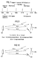
- Figure 1 is a diagram illustrating allocation of frequency spectrum for UMTS (Universal Mobile Telecommunications Standard),
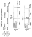
- Figure 2 is a diagram illustrating the basic method of time multiplexing uplink and downlink dedicated channels and the downlink shared channel DSCH operating on a different frequency,
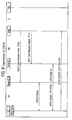
- Figure 3 is a diagram illustrating communications between a base station (BS) and user equipment (UE) and from a supplementary transmitter to the user equipment.
- Figure 4 is a diagram illustrating a first preferred method of data transport on the downlink shared channel (DSCH), and
- Figure 5 is a diagram illustrating a second preferred method of data transport on the downlink shared channel (DSCH),
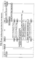
- Figure 6 is a diagram illustrating the process of reconfiguring the system so as to incorporate the supplementary transmitter,
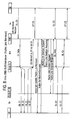
- Figure 7 is a diagram illustrating addition of a radio link by way of a soft handover,
- Figure 8 is a diagram illustrating removal of a radio link by way of a soft handover,
- Figure 9 is a diagram illustrating transmission on the downlink shared channl (DSCH), and
- Figure 10 is a diagram illustrating the method of time multiplexing with the uplink shared channel (CPCH) sent at a different frequency to the dedicated channels.
-
- The frequency spectrum allocation for UMTS is shown in Figure 1.
- The so-called TDD unpaired band in the International Mobile Telecommunication specification IMT2000 comprises of several channels with a bandwidth of 5MHz, allocated between 1900 MHz and 1920 MHz and between 2010 and 2025 MHz . The FDD spectrum is allocated as 12 paired channels with a bandwidth of 5 MHz and spaced by 190 MHz. The uplink band uses frequencies between 1920 MHz and 1980 MHz, while the downlink band is between 2110 MHz and 2170 MHz.
- From Figure 1, it will be seen that in order to use the TDD band as an extra downlink capacity for data, the following constraints apply:
- the user equipment UE must be able to receive in the 1900 to 1920 MHz band, while its normal receiving band, is 2110 to 2170 MHz (frequency division duplex).
- the base station must be able to transmit in the 1900 to 1920 MHz band, while it's 'normal' transmit band is 2110 to 2170 MHz.
- Basically the preferred method consists in using 5 MHz channels of the TDD band as an extra downlink channel. A supplementary transmitter to the base station transmits a FDD type of frame configured with Downlink Shared Channels (DSCH) that UE's can periodically decode.
- From a radio point if view, it is possible to use a TDD channel as a downlink extra capacity for data, provided that:
- the UE is capable of receiving in the TDD band,
- protocol arrangements are such that the UE receives data in the TDD band at instants in time when it is not transmitting,
- the base station and supplementary transmitter are physically separated, or alternatively, suitable filtering is installed on site.
- In order to involve as few changes as possible to the FDD standard (as currently defined), the base station transmits a signal framed as in FDD.
- The data transmitted on the extra downlink carrier could be carried on dedicated channels, common channels or shared channels. However the dedicated channel, as currently defined, requires simultaneous uplink and downlink transmission. Modification to this would in fact be the definition of a new type of channel. Also, use of the common channels presents more or less the same problem. Moreover, common channels are not well suited for transport of high volumes of data. Accordingly, it was felt that shared channels transmitted on the new downlink carrier appear as the best suited way to efficiently transmit high volumes of data from the network to UE's.
- As currently defined by 3GPP, shared channels can only be operated in conjunction with at least one dedicated channel (TS 25.302 §8.2). Therefore, a UE which needs data transmission with the network, establishes a low bit rate FDD Dedicated channel (DCH), as currently defined by the 3GPP FDD standards. When the network detects that the UE is temporarily receiving high volumes of data, the high bit rate shared channel (DSCH) of the extra downlink carrier is used, instead of the DCH.
- Because reception on the extra channel is not possible while the UE transmits, the compressed mode (as defined in TS 25.212 §4.4) is used to temporarily 'leave' the FDD carrier, and go to receive high volume of data on the extra carrier. Fig. 2 depicts this behaviour. Extra protocols ensure detection by the user equipment of the supplementary channel DLO through its pilot, along with Synchronisation Channel SCH and Physical-Common Control Physical Channel P-CCPCH control channels. These indicate that it is a supplementary channel and transmit the Data using the DSCH frame format.
- The basic system arrangement is shown in Figure 3. A base station BS is provided which communicates with a user equipment UE using appropriate dedicated control channels, denoted DL1 for the downlink and UL2 for the uplink in Figure 3. The uplink channel UL2 has frequency f2 and the downlink channel DL1 has a frequency f1 which is offset.
- In addition, a supplementary transmitter ST is provided which transmits downlink to the user equipment using a further channel DLo at a further frequency fo. This further channel DLo is part of the downlink shored channel DSCH and is used to carry data to the user equipment UE.
- As shown in Figure 2, the shared channel DLo is time duplexed with the dedicated downlink channel DL1. As shown in Figure 4, the transmission of data on channel DLo occurs continuously over several frames in systems more suited to static situations.
- In systems where high user equipment mobility occurs, the time multiplexing is done every frame as shown in Figure 5. As defined by the rules of the compressed mode of operation, the time during which the UE is allowed to leave the FDD carrier DL1, UL2, is relatively short (7 slots per frame, 14 consecutive slots at the maximum). This is however long enough to download high volumes of data, particularly if small spreading factors are used on the DSCH, and the operation is repeated at every frame. Moreover, this mode of operation allows
- power control on the DSCH, Traffic Power Control bits being transmitted over the DCH,
- acknowledgements of data received on DSCH, through the DCH.
- Because a UE has to get synchronized to the transmitting base station, and because the UE has to report to the network whether the extra carrier can be received (mobility aspects), the following physical channels are the only ones to be required on the extra downlink carrier:
- SCH for synchronization purposes
- P-CCPCH to carry the broadcast channel (BCH)
- PDSCH to carry the Downlink Shared Channel (DSCH).
- Using a TDD channel as a permanent downlink channel involves interference at the base station. Continuous transmission in the TDD band causes interference for a standard FDD base station receiving in the FDD uplink band. However, this problem is not specific to the mode of operation proposed here. It also exists with standard TDD base stations. Solutions may involve improved characteristics (at one or both of either the base station and supplementary transmitter) for adjacent channel filtering, or geographical separation of the base station and supplementary transmitter where it has been found that the supplementary transmitter has to be at least 100m away from the main base station.
- Using the TDD band as an extra downlink channel for data also involves interference issues for the UE.
- It is unpractical that an UE transmits in the FDD uplink band, while receiving in the TDD band. Therefore using the TDD band as an extra downlink capacity is only done at instants in time when the UE is not transmitting.
- A standard FDD UE transmitting in the uplink FDD band can cause a interference to a nearby UE receiving in the TDD band. Such interference is mitigated by the user of the TDD band reporting interference measurements, and the network not allocating resources at certain times where necessary in consequence.
- An example of the scheme in a UMTS System for call set up using DSCH on a supplementary channel is shown in Figures 6 to 9.
- To send data using DSCH on the supplementary transmitter ST over a supplementary RF band (f3), it is necessary to reconfigure an established radio link over the controlling base station (BS) (also referred to as Node B) and the User Equipment.
- Figures 6 to 9 show the message blocks that are needed to process the communication through such DSCH channel. They show how a Radio Network Controller RNC would schedule the transmission of data over both the Dedicated Channel DCHand the new Downlink Shared Channel, so that they are all 'readable' by the User Equipment UE. This has similarities with what happens when a standard DSCH is used while a UE is in handover. In such case DCH goes transparently from use by controlling Radio Network Controller CRNC to the base station (Node B) through the Drift Radio Network Controller DRNC, while DSCH data are transmitted from Controlling Radio Network Controller CRNC to Drift Radio Network Controller DRNC, for scheduling and transmission.
- As shown in Figure 6, radio link configuration is used to adapt the data flow rate (increase or decrease).If the requested data flow rate is sufficiently high, the operation in compressed mode is instigated whereby the time frame is divided into two parts, one for DCH and the other for DSCH with only one being used at any time instant. The data flow is adapted by modifying the spreading factor for DCH and DSCH. Note also that the ratio of transmission time slots between DCH and DSCH could also be varied as a way of increasing or decreasing the traffic ratio or capacity between DCH for uplink and DSCH on downlink channels. For reference in UTRAN FDD (UMTS Terrestrial Radio Access Network - Frequency Division Duplex) Standards - Compliant Systems compressed mode the maximum number of timeslots per frame usable for DSCH is seven. In other systems this can be allowed to be up to fourteen slots per frame. Figure 6 shows the messaging for the base station (Node B) and supplementary transmitter ST (here denoted Node B_U in the Figures 6 to 9 for the Radio Links Configuration set-up followed by Radio Resource Control RRC set-up in UE. This is initial preparation for the higher layers within the UMTS cellular system.
- Figure 7 shows the message sequence as a signalling block for initiating the DSCH data transfer from the supplementary transmitter ST denoted Node B_U.
- Figure 8 shows the message sequence as a signalling block for closing the DSCH data transfer from the supplementary transmitter ST denoted Node B_U.
- Figure 9 shows the message sequence as a signalling block for transmission of data over the DSCH channel active over from the supplementary transmitter denoted Node B_U.
- The Radio Network Controller RNC node schedules all the traffic sessions by controlling the timings of the DCH and DSCH transmissions per compressed mode frame. This frame structure is repeated for as long as the session lasts, or in other embodiments, it can be adaptive over time current to traffic behaviour so as to ensure efficient use of channel resource. There is a need to allow for a guard period between DCH and DSCH transmissions due to the physical separation between the base station (Node B) and supplementary transmitter (Node B_U). For example, the DCH transmission should start at the beginning of the time slot programmed for the end of compressed mode. The guard period is taken from the last time slot of compressed mode. This sequence continues until the end of transmission or a modification of data flow rate. Sequencing a mixture of the above messages, user traffic can be managed over the DCH and DSCH channels for the UE.
- This scheme is particularly suitable for use within buildings or for other low mobility applications.
- Possible applications include providing UPD (unit packet data) service for a multimedia service downlink where all the frame is used as downlink (DL) for several frames. An application using TCP (traffic control protocol) can also be used for several frames, however this can be improved by restricting the DL0 to a portion of the frame leaving some period for signalling. In terms of packet control, options include:
- Use the DL0 as the UPD only broadcast for the total duration of the frame.
- Use the DL0 in portion of the frame and will use a small portion for DL1 and UL2 for signalling and other power control etc... to be useful as a more reliable TCP protocol.
- Use DL0 for TCP as a broadcast for the entire duration of the frame.
- The proportion of time, allocated to each channel UL2 and DLO can either be variable or fixed.
- As regards transmission scheduling a radio network controller would schedule the transmission of data over both the DCH from the base station and the new DSCH from the supplementary transmitter, so that they are all 'readable' by the UE.
- This may seem quite a complex task, however it has probably similarities with what happens when a standard DSCH is used while a UE is in handover. In this case DCH goes transparently from CRNC to Node b through the DRNC, while DSCH data are transmitted from Control Radio Network Controller CRNC to Drift Radio Network Controller DRNC, for scheduling and transmission.
- Where it is desired to send relatively large amounts of data uplink from a user equipment UE to a base station BS an alternative system as shown in Figure 10 is provided. Instead of a supplementary transmitter, a supplementary receiver SR is provided at the base station. This receives the extra data from the user equipment as a channel ULO carried on the common packet channel CPCH.
Claims (9)
- Wireless telecommunication apparatus comprising a base station (BS) and a user terminal (UE), in use the base station sending some data to the user terminal on a first channel (DL1) at a first frequency (f1) in selected time slots within time frames and the user terminal sending some data to the base station on a second channel (UL2) of a second frequency (f2) in selected time slots within time frames,the first frequency and second frequency being offset,the apparatus further comprising a unit operative to transmit further data to or receive further data from the user terminal on a third channel (DL0) at a third frequency (f3), different from the first frequency and second frequency, and in time slots in which data is not sent on the first channel nor the second channel.
- Apparatus according to claim 1 in which the third channel is set on a bearer channel shared between a plurality of user terminals.
- Apparatus according to claim 1 or claim 2 being a UMTS network.
- Apparatus according to claim 3, in which the third channel is sent downlink and the unit is a transmitter operative to transmit the third channel on the Down Link Shared Channel (DSCH).
- Apparatus according to claim 3 in which the third channel is sent uplink and the unit is a receiver operative to receive the third channel on the Common Packet Channel.
- Apparatus according to any preceding claim in which the unit is at least approximately 100 metres from the base station.
- Apparatus according to any preceding claim, in which the first frequency and second frequency are a duplex pair of frequencies in accordance with IMT2000 and the third frequency is any available other frequency.
- Apparatus according to any preceding claim, in which the first frequency is in the 1920 to 1980 MHz band, the second frequency is in 2110 to 2170 MHz band, and the third frequency is in the band 1900 to 1920 MHz.
- A method of wireless telecommunication comprising the steps of:to a user terminal transmitting downlink some data on a first channel in selected time slots within time frames and at a first frequency,transmitting from the user terminal uplink some data on a second channel in selected time slots within time frames and at a second frequency,transmitting or receiving respectively to or from the user terminal further data on a third channel at a third frequency,data being sent on the third channel in timeslots in which data is not sent on the first channel nor the second channel.
Priority Applications (5)
| Application Number | Priority Date | Filing Date | Title |
|---|---|---|---|
| EP01304097A EP1255363B1 (en) | 2001-05-04 | 2001-05-04 | Wireless telecommunications system and method for asymmetric data transmission |
| DE60129108T DE60129108T2 (en) | 2001-05-04 | 2001-05-04 | Radio telecommunication system and method for asymmetric data transmission |
| JP2002130243A JP2003037869A (en) | 2001-05-04 | 2002-05-02 | Radio communication equipment, especially, equipment of umts or other third generation type, and method of radio communication |
| US10/138,214 US20020164986A1 (en) | 2001-05-04 | 2002-05-02 | Wireless telecommunications apparatus in particular of UMTS or other third generation type and a method of wireless telecommunication |
| KR10-2002-0024324A KR100497882B1 (en) | 2001-05-04 | 2002-05-03 | Wireless telecommunications apparatus in particular of umts or other third generation type and a method of wireless telecommunication |
Applications Claiming Priority (1)
| Application Number | Priority Date | Filing Date | Title |
|---|---|---|---|
| EP01304097A EP1255363B1 (en) | 2001-05-04 | 2001-05-04 | Wireless telecommunications system and method for asymmetric data transmission |
Publications (2)
| Publication Number | Publication Date |
|---|---|
| EP1255363A1 true EP1255363A1 (en) | 2002-11-06 |
| EP1255363B1 EP1255363B1 (en) | 2007-06-27 |
Family
ID=8181950
Family Applications (1)
| Application Number | Title | Priority Date | Filing Date |
|---|---|---|---|
| EP01304097A Expired - Lifetime EP1255363B1 (en) | 2001-05-04 | 2001-05-04 | Wireless telecommunications system and method for asymmetric data transmission |
Country Status (5)
| Country | Link |
|---|---|
| US (1) | US20020164986A1 (en) |
| EP (1) | EP1255363B1 (en) |
| JP (1) | JP2003037869A (en) |
| KR (1) | KR100497882B1 (en) |
| DE (1) | DE60129108T2 (en) |
Cited By (1)
| Publication number | Priority date | Publication date | Assignee | Title |
|---|---|---|---|---|
| CN101009514B (en) * | 2006-01-26 | 2011-04-06 | 中兴通讯股份有限公司 | A system and method for cooperative dual duplex |
Families Citing this family (18)
| Publication number | Priority date | Publication date | Assignee | Title |
|---|---|---|---|---|
| JP3543770B2 (en) * | 2001-02-20 | 2004-07-21 | 日本電気株式会社 | MOBILE COMMUNICATION SYSTEM, MOBILE TERMINAL, TRANSMISSION DIVERSITY APPLICATION METHOD USED FOR THEM, AND PROGRAM THEREOF |
| US7528614B2 (en) | 2004-12-22 | 2009-05-05 | Applied Materials, Inc. | Apparatus and method for voltage contrast analysis of a wafer using a tilted pre-charging beam |
| EP1965600B1 (en) * | 2002-09-20 | 2013-11-06 | Fujitsu Limited | Resource information transmission for multicasting in a wireless network |
| CN1843002B (en) * | 2003-08-26 | 2016-05-11 | 皇家飞利浦电子股份有限公司 | point-to-multipoint transmission |
| GB2413240A (en) * | 2004-04-13 | 2005-10-19 | Ipwireless Inc | Dynamic channel assignment in a TDD communication system |
| KR20060117186A (en) * | 2005-05-13 | 2006-11-16 | 삼성전자주식회사 | Apparatus and method for assigning a channel in a wireless local area network mesh communication system |
| US8031669B2 (en) * | 2005-07-29 | 2011-10-04 | Nextel Communications Inc. | Systems and methods for increasing base station capacity |
| KR100856207B1 (en) * | 2005-09-13 | 2008-09-03 | 삼성전자주식회사 | Communication method and system for using time division duplex scheme and frequency division duplex scheme |
| EP1860814A1 (en) * | 2006-05-26 | 2007-11-28 | Nokia Siemens Networks Gmbh & Co. Kg | Method for interference reduction |
| US8738103B2 (en) | 2006-07-18 | 2014-05-27 | Fractus, S.A. | Multiple-body-configuration multimedia and smartphone multifunction wireless devices |
| EP2262334B1 (en) * | 2008-03-31 | 2020-03-25 | Sharp Kabushiki Kaisha | Communication method and base station apparatus |
| US9369990B2 (en) * | 2008-08-11 | 2016-06-14 | Qualcomm Incorporated | Multi-carrier design for control and procedures |
| CN104980260A (en) | 2008-11-21 | 2015-10-14 | 交互数字专利控股公司 | Method and apparatus for multiple carrier utilization in wireless communications |
| CN105187083B (en) * | 2013-05-30 | 2017-08-11 | 华为技术有限公司 | RF receiving/transmission device, terminal and method |
| US10742311B2 (en) | 2017-03-02 | 2020-08-11 | Lynk Global, Inc. | Simplified inter-satellite link communications using orbital plane crossing to optimize inter-satellite data transfers |
| US10084535B1 (en) | 2017-04-26 | 2018-09-25 | UbiquitiLink, Inc. | Method and apparatus for handling communications between spacecraft operating in an orbital environment and terrestrial telecommunications devices that use terrestrial base station communications |
| US10951305B2 (en) | 2018-04-26 | 2021-03-16 | Lynk Global, Inc. | Orbital base station filtering of interference from terrestrial-terrestrial communications of devices that use protocols in common with orbital-terrestrial communications |
| US11863250B2 (en) | 2021-01-06 | 2024-01-02 | Lynk Global, Inc. | Satellite communication system transmitting navigation signals using a wide beam and data signals using a directive beam |
Citations (5)
| Publication number | Priority date | Publication date | Assignee | Title |
|---|---|---|---|---|
| US5754961A (en) * | 1994-06-20 | 1998-05-19 | Kabushiki Kaisha Toshiba | Radio communication system including SDL having transmission rate of relatively high speed |
| US5956642A (en) * | 1996-11-25 | 1999-09-21 | Telefonaktiebolaget L M Ericsson | Adaptive channel allocation method and apparatus for multi-slot, multi-carrier communication system |
| FR2777407A1 (en) * | 1998-04-10 | 1999-10-15 | Wavecom Sa | CELLULAR DOWNLINK CELLULAR RADIOTELEPHONY SIGNAL, METHOD, SYSTEM, MOBILE, AND BASE STATION THEREFOR |
| DE19857041A1 (en) * | 1998-12-10 | 2000-06-15 | Siemens Ag | Method for data transmission in a radio communication system |
| EP1069790A2 (en) * | 1999-07-10 | 2001-01-17 | Hyundai Electronics Industries Co., Ltd. | Method and apparatus for dynamically assigning channel in asynchronous mobile communication system |
Family Cites Families (9)
| Publication number | Priority date | Publication date | Assignee | Title |
|---|---|---|---|---|
| US5603081A (en) * | 1993-11-01 | 1997-02-11 | Telefonaktiebolaget Lm Ericsson | Method for communicating in a wireless communication system |
| JP3280830B2 (en) * | 1994-06-20 | 2002-05-13 | 株式会社東芝 | Wireless communication system and wireless communication base station |
| US6597680B1 (en) * | 1998-11-16 | 2003-07-22 | Telefonaktiebolaget Lm Ericsson (Publ) | Packet traffic channel reassignment |
| EP1020999A1 (en) * | 1998-12-18 | 2000-07-19 | Nortel Matra Cellular | Mobile communication system with compressed mode operation and method of operating the same |
| DE69919747T2 (en) * | 1999-07-13 | 2005-01-27 | Alcatel | A method of enhancing the performance of a mobile radio communication system using a power control algorithm |
| FI112772B (en) * | 2000-02-18 | 2003-12-31 | Nokia Corp | Reduction of interference in inter-frequency measurement |
| FR2809554B1 (en) * | 2000-05-23 | 2002-08-16 | Mitsubishi Electric Telecom Eu | METHOD FOR SYNCHRONIZING AT LEAST ONE MOBILE STATION IN A MOBILE TELECOMMUNICATION NETWORK HAVING A MODIFIED SYNCHRONIZATION CHANNEL STRUCTURE |
| US6650905B1 (en) * | 2000-06-30 | 2003-11-18 | Nokia Mobile Phones, Ltd. | Universal mobile telecommunications system (UMTS) terrestrial radio access (UTRA) frequency division duplex (FDD) downlink shared channel (DSCH) power control in soft handover |
| US6970438B2 (en) * | 2001-02-16 | 2005-11-29 | Nokia Mobile Phones Ltd. | Method and device for downlink packet switching |
-
2001
- 2001-05-04 EP EP01304097A patent/EP1255363B1/en not_active Expired - Lifetime
- 2001-05-04 DE DE60129108T patent/DE60129108T2/en not_active Expired - Lifetime
-
2002
- 2002-05-02 JP JP2002130243A patent/JP2003037869A/en active Pending
- 2002-05-02 US US10/138,214 patent/US20020164986A1/en not_active Abandoned
- 2002-05-03 KR KR10-2002-0024324A patent/KR100497882B1/en not_active IP Right Cessation
Patent Citations (5)
| Publication number | Priority date | Publication date | Assignee | Title |
|---|---|---|---|---|
| US5754961A (en) * | 1994-06-20 | 1998-05-19 | Kabushiki Kaisha Toshiba | Radio communication system including SDL having transmission rate of relatively high speed |
| US5956642A (en) * | 1996-11-25 | 1999-09-21 | Telefonaktiebolaget L M Ericsson | Adaptive channel allocation method and apparatus for multi-slot, multi-carrier communication system |
| FR2777407A1 (en) * | 1998-04-10 | 1999-10-15 | Wavecom Sa | CELLULAR DOWNLINK CELLULAR RADIOTELEPHONY SIGNAL, METHOD, SYSTEM, MOBILE, AND BASE STATION THEREFOR |
| DE19857041A1 (en) * | 1998-12-10 | 2000-06-15 | Siemens Ag | Method for data transmission in a radio communication system |
| EP1069790A2 (en) * | 1999-07-10 | 2001-01-17 | Hyundai Electronics Industries Co., Ltd. | Method and apparatus for dynamically assigning channel in asynchronous mobile communication system |
Cited By (1)
| Publication number | Priority date | Publication date | Assignee | Title |
|---|---|---|---|---|
| CN101009514B (en) * | 2006-01-26 | 2011-04-06 | 中兴通讯股份有限公司 | A system and method for cooperative dual duplex |
Also Published As
| Publication number | Publication date |
|---|---|
| EP1255363B1 (en) | 2007-06-27 |
| DE60129108D1 (en) | 2007-08-09 |
| US20020164986A1 (en) | 2002-11-07 |
| KR100497882B1 (en) | 2005-06-29 |
| DE60129108T2 (en) | 2008-02-28 |
| KR20020084826A (en) | 2002-11-11 |
| JP2003037869A (en) | 2003-02-07 |
Similar Documents
| Publication | Publication Date | Title |
|---|---|---|
| US11452084B2 (en) | Method and apparatus for effectively providing TDD configuration information to user equipment and determining uplink transmission timing in mobile communication system supporting TDD | |
| US11503558B2 (en) | Method and apparatus for time synchronization in device-to-device communication | |
| EP1255363B1 (en) | Wireless telecommunications system and method for asymmetric data transmission | |
| EP3908043B1 (en) | Resource allocation | |
| EP2526640B1 (en) | Method and apparatus for activating carriers in mobile communication system | |
| KR100396509B1 (en) | Apparatus for gated transmission of dedicated physical control channel and method thereof in mobile communication system | |
| EP2938012B1 (en) | Method and apparatus for controlling measurement gaps of serving cells in mobile communication system | |
| CN105723770B (en) | Method and apparatus for controlling power headroom reporting and hybrid automatic retransmission | |
| WO2015126027A1 (en) | Method for transreceiving signal using user-specific flexible tdd technology in wireless communication system and device for same | |
| KR20140135331A (en) | Method and apparatus of operation for dynamic time division duplex in wireless communication system | |
| CN111937428B (en) | Apparatus and method for measurement in wireless communication system | |
| US7170943B1 (en) | Control channel for a wireless digital subscriber line system | |
| KR102396149B1 (en) | Method and apparatus to efficiently provide TDD configuration to terminal in the mobile communication system |
Legal Events
| Date | Code | Title | Description |
|---|---|---|---|
| PUAI | Public reference made under article 153(3) epc to a published international application that has entered the european phase |
Free format text: ORIGINAL CODE: 0009012 |
|
| AK | Designated contracting states |
Kind code of ref document: A1 Designated state(s): AT BE CH CY DE DK ES FI FR GB GR IE IT LI LU MC NL PT SE TR |
|
| AX | Request for extension of the european patent |
Free format text: AL;LT;LV;MK;RO;SI |
|
| 17P | Request for examination filed |
Effective date: 20030425 |
|
| AKX | Designation fees paid |
Designated state(s): DE FR GB |
|
| GRAP | Despatch of communication of intention to grant a patent |
Free format text: ORIGINAL CODE: EPIDOSNIGR1 |
|
| GRAS | Grant fee paid |
Free format text: ORIGINAL CODE: EPIDOSNIGR3 |
|
| GRAA | (expected) grant |
Free format text: ORIGINAL CODE: 0009210 |
|
| AK | Designated contracting states |
Kind code of ref document: B1 Designated state(s): DE FR GB |
|
| REG | Reference to a national code |
Ref country code: GB Ref legal event code: FG4D |
|
| REF | Corresponds to: |
Ref document number: 60129108 Country of ref document: DE Date of ref document: 20070809 Kind code of ref document: P |
|
| ET | Fr: translation filed | ||
| PLBE | No opposition filed within time limit |
Free format text: ORIGINAL CODE: 0009261 |
|
| STAA | Information on the status of an ep patent application or granted ep patent |
Free format text: STATUS: NO OPPOSITION FILED WITHIN TIME LIMIT |
|
| 26N | No opposition filed |
Effective date: 20080328 |
|
| PGFP | Annual fee paid to national office [announced via postgrant information from national office to epo] |
Ref country code: GB Payment date: 20100331 Year of fee payment: 10 |
|
| PGFP | Annual fee paid to national office [announced via postgrant information from national office to epo] |
Ref country code: FR Payment date: 20100611 Year of fee payment: 10 |
|
| PGFP | Annual fee paid to national office [announced via postgrant information from national office to epo] |
Ref country code: DE Payment date: 20100521 Year of fee payment: 10 |
|
| GBPC | Gb: european patent ceased through non-payment of renewal fee |
Effective date: 20110504 |
|
| REG | Reference to a national code |
Ref country code: FR Ref legal event code: ST Effective date: 20120131 |
|
| REG | Reference to a national code |
Ref country code: DE Ref legal event code: R119 Ref document number: 60129108 Country of ref document: DE Effective date: 20111201 |
|
| PG25 | Lapsed in a contracting state [announced via postgrant information from national office to epo] |
Ref country code: FR Free format text: LAPSE BECAUSE OF NON-PAYMENT OF DUE FEES Effective date: 20110531 |
|
| PG25 | Lapsed in a contracting state [announced via postgrant information from national office to epo] |
Ref country code: GB Free format text: LAPSE BECAUSE OF NON-PAYMENT OF DUE FEES Effective date: 20110504 |
|
| PG25 | Lapsed in a contracting state [announced via postgrant information from national office to epo] |
Ref country code: DE Free format text: LAPSE BECAUSE OF NON-PAYMENT OF DUE FEES Effective date: 20111201 |