EP1251328A2 - System and method for determining the position or/and the orientation of two objects relative to each other, as well as beam guidance device, interferometer system and device for modifying the optical pathlength for use in such a system and method - Google Patents
System and method for determining the position or/and the orientation of two objects relative to each other, as well as beam guidance device, interferometer system and device for modifying the optical pathlength for use in such a system and method Download PDFInfo
- Publication number
- EP1251328A2 EP1251328A2 EP02008409A EP02008409A EP1251328A2 EP 1251328 A2 EP1251328 A2 EP 1251328A2 EP 02008409 A EP02008409 A EP 02008409A EP 02008409 A EP02008409 A EP 02008409A EP 1251328 A2 EP1251328 A2 EP 1251328A2
- Authority
- EP
- European Patent Office
- Prior art keywords
- mirror
- radiation
- emitter
- objects
- arrangement
- Prior art date
- Legal status (The legal status is an assumption and is not a legal conclusion. Google has not performed a legal analysis and makes no representation as to the accuracy of the status listed.)
- Granted
Links
Images


Classifications
-
- G—PHYSICS
- G01—MEASURING; TESTING
- G01B—MEASURING LENGTH, THICKNESS OR SIMILAR LINEAR DIMENSIONS; MEASURING ANGLES; MEASURING AREAS; MEASURING IRREGULARITIES OF SURFACES OR CONTOURS
- G01B11/00—Measuring arrangements characterised by the use of optical techniques
- G01B11/002—Measuring arrangements characterised by the use of optical techniques for measuring two or more coordinates
- G01B11/005—Measuring arrangements characterised by the use of optical techniques for measuring two or more coordinates coordinate measuring machines
-
- G—PHYSICS
- G01—MEASURING; TESTING
- G01B—MEASURING LENGTH, THICKNESS OR SIMILAR LINEAR DIMENSIONS; MEASURING ANGLES; MEASURING AREAS; MEASURING IRREGULARITIES OF SURFACES OR CONTOURS
- G01B9/00—Measuring instruments characterised by the use of optical techniques
- G01B9/02—Interferometers
- G01B9/02015—Interferometers characterised by the beam path configuration
- G01B9/02027—Two or more interferometric channels or interferometers
- G01B9/02028—Two or more reference or object arms in one interferometer
-
- G—PHYSICS
- G01—MEASURING; TESTING
- G01B—MEASURING LENGTH, THICKNESS OR SIMILAR LINEAR DIMENSIONS; MEASURING ANGLES; MEASURING AREAS; MEASURING IRREGULARITIES OF SURFACES OR CONTOURS
- G01B9/00—Measuring instruments characterised by the use of optical techniques
- G01B9/02—Interferometers
- G01B9/02015—Interferometers characterised by the beam path configuration
- G01B9/02032—Interferometers characterised by the beam path configuration generating a spatial carrier frequency, e.g. by creating lateral or angular offset between reference and object beam
-
- G—PHYSICS
- G01—MEASURING; TESTING
- G01B—MEASURING LENGTH, THICKNESS OR SIMILAR LINEAR DIMENSIONS; MEASURING ANGLES; MEASURING AREAS; MEASURING IRREGULARITIES OF SURFACES OR CONTOURS
- G01B9/00—Measuring instruments characterised by the use of optical techniques
- G01B9/02—Interferometers
- G01B9/0209—Low-coherence interferometers
-
- G—PHYSICS
- G01—MEASURING; TESTING
- G01S—RADIO DIRECTION-FINDING; RADIO NAVIGATION; DETERMINING DISTANCE OR VELOCITY BY USE OF RADIO WAVES; LOCATING OR PRESENCE-DETECTING BY USE OF THE REFLECTION OR RERADIATION OF RADIO WAVES; ANALOGOUS ARRANGEMENTS USING OTHER WAVES
- G01S17/00—Systems using the reflection or reradiation of electromagnetic waves other than radio waves, e.g. lidar systems
- G01S17/02—Systems using the reflection of electromagnetic waves other than radio waves
- G01S17/06—Systems determining position data of a target
-
- G—PHYSICS
- G01—MEASURING; TESTING
- G01B—MEASURING LENGTH, THICKNESS OR SIMILAR LINEAR DIMENSIONS; MEASURING ANGLES; MEASURING AREAS; MEASURING IRREGULARITIES OF SURFACES OR CONTOURS
- G01B2290/00—Aspects of interferometers not specifically covered by any group under G01B9/02
- G01B2290/15—Cat eye, i.e. reflection always parallel to incoming beam
-
- G—PHYSICS
- G01—MEASURING; TESTING
- G01B—MEASURING LENGTH, THICKNESS OR SIMILAR LINEAR DIMENSIONS; MEASURING ANGLES; MEASURING AREAS; MEASURING IRREGULARITIES OF SURFACES OR CONTOURS
- G01B2290/00—Aspects of interferometers not specifically covered by any group under G01B9/02
- G01B2290/35—Mechanical variable delay line
Abstract
Description
Die Erfindung betrifft ein System zum interferometrischen Bestimmen einer Position zweier Objekte relativ zueinander. Insbesondere betrifft die Erfindung ein System zum interferometrischen Bestimmen von sowohl Position als auch Orientierung der beiden Objekte relativ zueinander. Weiterhin betrifft die Erfindung allgemein ein Verfahren zum Bestimmen von Position und Orientierung zweier Objekte relativ zueinander auf der Grundlage von wenigstens neun zwischen den beiden Objekten ermittelten Abständen. Dieses Verfahren ist insbesondere in dem System zum Bestimmen von Position und Orientierung der beiden Objekte relativ zueinander einsetzbar.The invention relates to a system for interferometric determination a position of two objects relative to each other. In particular, the invention relates to a system for interferometric Determine both position and orientation of the two objects relative to each other. Furthermore concerns the invention generally a method of determining of position and orientation of two objects relative to each other based on at least nine between the two Distances determined by objects. This procedure is special in the system for determining position and orientation of the two objects can be used relative to each other.
Weiterhin betrifft die Erfindung allgemein eine Strahlführungsanordnung zum Zuführen einer von einer Lichtquelle emittierten Strahlung zu einem Meßkopf, wobei Lichtquelle und Meßkopf relativ zueinander bewegbar sind oder/und die Strahlführungsanordnung sich ändernden Umwelteinflüssen ausgesetzt ist. Die Strahlführungsanordnung ist insbesondere in einem Sensorsystem oder in dem System zum Bestimmen von Position oder/und Orientierung der beiden Objekte relativ zueinander einsetzbar. Ferner betrifft die Erfindung eine Interferometeranordnung mit einer solchen Strahlführungsanordnung.Furthermore, the invention relates generally to a beam guidance arrangement for feeding one from a light source emitted radiation to a measuring head, light source and Measuring head are movable relative to each other and / or the beam guidance arrangement exposed to changing environmental influences is. The beam guidance arrangement is in particular in one Sensor system or in the system for determining position or / and orientation of the two objects relative to one another used. The invention further relates to an interferometer arrangement with such a beam guidance arrangement.
Weiterhin betrifft die Erfindung allgemein eine Vorrichtung zum Bereitstellen einer änderbaren optischen Weglänge bzw. eine Vorrichtung zum Bereitstellen einer änderbaren optischen Verzögerung, welche insbesondere in dem System zum Bestimmen von Position oder/und Orientierung der beiden Objekte relativ zueinander einsetzbar ist.Furthermore, the invention relates generally to a device to provide a changeable optical path length or a device for providing a changeable optical Delay, which is particularly to be determined in the system relative to the position and / or orientation of the two objects is applicable to each other.
Ferner betrifft die Erfindung ein Koordinatenmeßgerät und eine Werkzeugmaschine, bei der das System zum Bestimmen der Position oder/und Orientierung der beiden Objekte relativ zueinander eingesetzt ist.The invention further relates to a coordinate measuring machine and a machine tool in which the system for determining the Position and / or orientation of the two objects relative to one another is inserted.
Es ist bekannt, Abstandsänderungen zwischen zwei Objekten interferometrisch zu erfassen, indem an einem der Objekte ein Retroreflektor angebracht wird, und an dem anderen der beiden Objekte ein Emitter für kohärente Strahlung vorgesehen ist, die auf den Retroreflektor gerichtet ist. Die von dem Retroreflektor zu dem anderen Objekt hin zurückgeworfene Strahlung wird über einen entsprechenden Empfänger empfangen, mit der Strahlung der Quelle zur interferenten Überlagerung gebracht und mit einem Strahlungsintensitätsmesser erfaßt. Bei einer Änderung des Abstands zwischen den beiden Objekten ändert sich der optische Weg des zwischen den beiden Objekten hin und her reflektierten Strahls, so daß aufgrund der Interferenz Intensitätsmaxima und -minima erzeugt werden. Wird die Zahl der Intensitätsänderungen erfaßt, so kann auf die Größe der Abstandsänderung geschlossen werden. Eine Messung des absoluten Abstands zwischen den beiden Objekten ist dann möglich, wenn durch eine Referenzfahrt die beiden Objekte zu Beginn auf einen vorbestimmten bekannten Abstand voneinander gebracht werden und daraufhin die Änderungen von dem bekannten Abstand aus erfaßt werden.It is known to change distances between two objects interferometrically by entering one of the objects Retroreflector is attached, and to the other of the two Objects an emitter is provided for coherent radiation, which is aimed at the retroreflector. The one from the retroreflector radiation reflected back to the other object is received via a corresponding receiver with which Radiation from the source caused an interference interference and detected with a radiation intensity meter. At a Changing the distance between the two objects changes the optical path of between the two objects and forth reflected beam, so that due to the interference Intensity maxima and minima are generated. Will the Number of changes in intensity recorded, so can the size the change in distance can be closed. A measurement of the absolute The distance between the two objects is then possible if the two objects start with a reference run at a predetermined known distance from each other brought and then the changes from the known Distance can be detected from.
Aus WO 88/07656 ist ein System bekannt, um relative Änderungen der Position und der Orientierung zweier Objekte relativ zueinander zu erfassen. Hierzu sind an dem ersten Objekt drei mit Abstand voneinander angeordnete Retroreflektoren angebracht, und an dem zweiten Objekt sind sechs separat und mit Abstand voneinander angebrachte Interferometer-Emitter vorgesehen, deren ausgesendete Strahlung jeweils auf einen der Retroreflektoren gerichtet ist. Hierbei richten der erste, zweite und dritte Emitter jeweils ihre Strahlung auf den ersten Retroreflektor, der vierte und der fünfte Emitter richten ihre Strahlung auf den zweiten Retroreflektor und der sechste Emitter richtet seine Strahlung auf den dritten Retroreflektor. Durch die Bereitstellung der sechs Interferometer kann damit eine Änderung von sechs verschiedenen Abständen zwischen Orten an dem ersten bzw. zweiten Objekt erfaßt werden. War der Abstand zwischen den verschiedenen Orten an den beiden Objekten in einer Referenzstellung zu Beginn der Messung bekannt, so können auch nach Bewegung der beiden Objekte relativ zueinander die sechs Abstände absolut bestimmt werden. Aus den absoluten Werten der sechs Abstände kann dann die Position und die Orientierung der beiden Objekte relativ zueinander ermittelt werden.From WO 88/07656 a system is known for relative changes the position and orientation of two objects relative to capture each other. For this there are three on the first object spaced retroreflectors attached, and on the second object there are six separate and with Interferometer-emitters placed at a distance from each other the emitted radiation each on one of the Retroreflectors is aimed. Here, the first second and third emitters each emit their radiation on the first Retroreflector, the fourth and fifth emitter aim their radiation onto the second retroreflector and the the sixth emitter directs its radiation to the third Retroreflector. By providing the six interferometers can change six different distances between locations on the first and second objects, respectively become. Was the distance between the different places at the two objects in a reference position at the beginning the measurement known, so even after moving the two Objects relative to each other absolutely determined the six distances become. From the absolute values of the six distances can then determine the position and orientation of the two objects can be determined relative to each other.
Tritt bei diesem System während einer Abstands- bzw. Orientierungsänderung eine Unterbrechung eines der sechs Strahlen beispielsweise durch Umwelteinflüsse auf, so kann während dieser Unterbrechung eine Zählung der Intensitätsmaxima bzw. -minima nicht mehr erfolgen, so daß eine Bestimmung des absoluten Abstands zwischen den beiden Objekten ab diesem Zeitpunkt nicht mehr möglich ist. Ferner muß ein jeder Emitter seine Strahlung auf den ihm einzig zugeordneten Retroreflektor richten, so daß der Emitter eine entsprechende Strahlrichtungssteuerung umfaßt, um seine Strahlung ständig auf dem entsprechenden Retroreflektor gerichtet zu halten. Bei einer Strahlunterbrechung kann die Richtungssteuerung den Kontakt zu dem entsprechenden Retroreflektor verlieren.Occurs with this system during a change in distance or orientation an interruption of one of the six rays for example due to environmental influences, so during this interruption a count of the intensity maxima or -minima no longer take place, so that a determination of the absolute Distance between the two objects from this point on is no longer possible. Furthermore, every emitter its radiation onto the retroreflector assigned to it aim so that the emitter has a corresponding beam direction control includes to keep its radiation constantly on the keep appropriate retroreflector directed. At a Beam interruption can control the direction of contact lose to the corresponding retroreflector.
Wird die kohärente Strahlung dem Emitter durch einen herkömmlichen Ein-Moden-Lichtleiter zugeführt und durch diesen auch schließlich dem Detektor zugeführt, so tritt bei einer Änderung der relativen Position zwischen Quelle und Detektor einerseits und Emitter andererseits oder durch eine andere Einwirkung von Umwelteinflüssen auch eine Änderung der Übertragungseigenschaften der Lichtleitfaser auf. Dies kann zur Folge haben, daß das dem Detektor zugeführte Signal starken Schwankungen unterliegt, welche ebenfalls als durch Bewegung zwischen den beiden Objekten verursachte Intensitätsmaxima bzw. -minima interpretiert werden. Auch dies führt zu einer fehlerhaften Messung der Abstandsänderung.The coherent radiation is emitted by a conventional one A mode light guide supplied and through this finally fed to the detector, so occurs at one Change in relative position between source and detector on the one hand and emitters on the other hand or by another Effects of environmental influences also change the transmission properties the optical fiber. This can lead to As a result, the signal supplied to the detector is strong Is subject to fluctuations, which is also considered to be due to movement intensity maxima caused between the two objects or -minima are interpreted. This also leads to one incorrect measurement of the change in distance.
Aus den sechs ermittelten Abständen ist die Bestimmung der Position und Orientierung der beiden Objekte relativ zueinander mittels eines iterativen Rechenverfahrens, wie etwa eines herkömmlichen Gauß-Seidel-Verfahrens, möglich. Ein solches Rechenverfahren ist rechenintensiv und limitiert die Geschwindigkeit, mit der die ermittelte Position bzw. Orientierung pro Zeiteinheit aktualisiert werden kann.The determination of the is from the six determined distances Position and orientation of the two objects relative to each other using an iterative calculation method, such as one conventional Gauss-Seidel method possible. Such one Computing is computationally intensive and limits the speed, with the determined position or orientation can be updated per unit of time.
Es sind ferner interferometrische Verfahren bekannt, bei denen der Abstand zwischen zwei Objekten einen optischen Weg in einem Meßzweig des Interferometers bereitstellt und bei denen dieser optische Weg mit einem in einem Referenzzweig des Interferometers bereitgestellten änderbaren bekannten optischen Weg verglichen wird, so daß auf diese Weise eine Bestimmung des absoluten Abstands zwischen den beiden Objekten möglich ist. Die hierzu bekannten Vorrichtungen zum Bereitstellen eines optischen Wegs in dem Referenzzweig haben einerseits einen zu kleinen Hub, das heißt einen zu kleinen Änderungsbereich der optischen Weglänge, um große Abstandsänderungen zwischen den beiden Objekten abgleichen zu können, oder/und sie sind andererseits zu langsam, um große Änderungen des optischen Wegs schnell bereitstellen zu können, was wiederum die Abstandsmeßrate begrenzt.Interferometric methods are also known for which the distance between two objects is an optical path provides in a measuring branch of the interferometer and at which this optical path with one in a reference branch of the interferometer provided changeable known optical Way is compared, so that a determination the absolute distance between the two objects is possible. The known devices for providing an optical path in the reference branch on the one hand, a stroke that is too small, that is, a stroke that is too small Change range of the optical path length to large changes in distance to be able to match between the two objects or / and on the other hand they are too slow to make big changes the optical path to be able to quickly provide what again the distance measurement rate is limited.
Demgemäß ist es eine Aufgabe der vorliegenden Erfindung, ein System zum Bestimmen einer Position zweier Objekte relativ zueinander bereitzustellen, welches störungsunanfällig ist. Ferner ist eine Aufgabe ein solches System bereitzustellen, welches die Messung eines absoluten Abstands ermöglicht. Eine weitere Aufgabe ist es, ein solches System bereitzustellen, welches auch die Orientierung der beiden Objekte relativ zueinander bestimmen kann.Accordingly, it is an object of the present invention to provide a System for determining a position of two objects relative to provide each other, which is not susceptible to interference. Another object is to provide such a system, which enables the measurement of an absolute distance. A another task is to provide such a system which is also the orientation of the two objects relative to each other can determine.
Eine weitere Aufgabe der Erfindung ist es, ein Verfahren zum Bestimmen der Position oder/und der Orientierung der beiden Objekte relativ zueinander bereitzustellen, welches weniger rechenintensiv ist.Another object of the invention is to provide a method for Determine the position and / or the orientation of the two To provide objects relative to each other, which less is computationally intensive.
Eine weitere Aufgabe der Erfindung ist es, eine Strahlführungsanordnung mit einer Lichtleiteranordnung vorzuschlagen, welche weniger anfällig auf Bewegungen der Lichtleiteranordnung oder/und andere Umwelteinflüsse auf die Lichtleiteranordnung ist. Eine weitere Aufgabe der Erfindung ist es, eine Interferometeranordnung vorzuschlagen, deren Meßzweig relativ zur Strahlungsquelle bewegbar und dabei weniger störungsanfällig ist.Another object of the invention is a beam guidance arrangement to propose with an optical fiber arrangement, which are less susceptible to movement of the light guide assembly or / and other environmental influences on the Light guide arrangement is. Another object of the invention is to propose an interferometer arrangement whose Measuring branch movable relative to the radiation source and thereby is less prone to failure.
Eine weitere Aufgabe der vorliegenden Erfindung ist es, eine Vorrichtung zum Bereitstellen einer änderbaren optischen Weglänge vorzuschlagen, welche einen großen Hub bereitstellt. Ferner ist es eine Aufgabe, eine solche Vorrichtung vorzuschlagen, deren Hub schnell änderbar ist.Another object of the present invention is to provide a Device for providing a changeable optical path length to propose which provides a large hub. It is also an object to propose such a device whose stroke can be changed quickly.
Unter einem ersten Aspekt sieht die Erfindung ein System zum Bestimmen einer Position zweier Objekte relativ zueinander vor, wobei wenigstens drei Abstände zwischen wenigstens einem Ort an einem ersten der beiden Objekte und wenigstens drei Orten an dem zweiten der beiden Objekte interferometrisch bestimmt werden. Hierzu ist eine Quelle ausreichend kohärenter Strahlung vorgesehen, um ein von den Abständen der Orte abhängiges Interferenzsignal zu erzeugen. Hierzu wird von der Quelle abgeleitete Strahlung zur Überlagerung gebracht mit Strahlung, die einen Meßzweig durchlaufen hat, der die Strecken zwischen den auf dem ersten Objekt einerseits und dem auf dem zweiten Objekt andererseits vorgesehenen Orten als optischen Weg umfaßt. Ein Rechner wertet das entstehende Interferenzsignal aus und bestimmt daraus die Abstände zwischen den entsprechenden Orten und hieraus wiederum die Position der beiden Objekte relativ zueinander. Die Orte an dem zweiten Objekt sind durch wenigstens drei daran angebrachte Retroreflektoren bestimmt, deren Abstände zueinander festgelegt und bekannt sind. Die an dem ersten Objekt festgelegten Orte sind zum einen ein Emitter für die von der Quelle bereitgestellte Strahlung, welcher diese Strahlung in einen solchen Raumwinkelbereich aussendet, daß die wenigstens drei Retroreflektoren in diesem Raumwinkelbereich enthalten sind. Der Raumwinkelbereich ist dabei weiter so groß ausgestaltet, daß die Retroreflektoren darin auch noch bei einer relativen Verschiebung der beiden Objekte in einem vorgesehenen Verschiebungsvolumen in dem Raumwinkelbereich enthalten sind. Als ein weiterer Ort ist an dem ersten Objekt ein Empfänger für Strahlung festgelegt, welcher die von dem Emitter ausgesendete und von den Retroreflektoren zurückgeworfene Strahlung empfängt und schließlich zur Überlagerung mit der weiteren von der Quelle abgeleiteten Strahlung dem Strahlungsintensitätsmesser zuführt.In a first aspect, the invention provides a system for Determine a position of two objects relative to each other before, with at least three distances between at least one Place at a first of the two objects and at least three Locations at the second of the two objects determined interferometrically become. A source is sufficiently coherent for this Radiation is provided to be dependent on the distances between the locations Generate interference signal. For this, the Source-derived radiation is superimposed with Radiation that has passed through a measuring branch that Routes between those on the first object and the locations provided on the second object included as an optical path. A computer evaluates the resulting Interference signal and determines the distances therefrom between the corresponding locations and from this in turn the Position of the two objects relative to each other. The places at the second object are attached to it by at least three Retroreflectors determine their distances from each other are established and known. The set on the first object On the one hand, places are an emitter for those from the source provided radiation, which this radiation into a emits such solid angle range that the at least three Retroreflectors are included in this solid angle range. The solid angle range is further designed so large that the retroreflectors in it also at a relative Displacement of the two objects in an intended displacement volume are included in the solid angle range. As a further location there is a receiver on the first object for radiation which is the one emitted by the emitter and radiation reflected by the retroreflectors receives and finally to overlap with the other radiation derived from the source to the radiation intensity meter supplies.
Indem der wenigstens eine Emitter seine Strahlung in den Raumwinkelbereich aussendet, der wenigstens drei Retroreflektoren enthält, ist eine Strahllenkungseinrichtung, welche einen Meßstrahl herkömmlicherweise selektiv lediglich einem Retroreflektor zuführt und entsprechend angesteuert werden muß, um diesen Retroreflektor ständig zu verfolgen, nicht unbedingt notwendig.By the at least one emitter emitting its radiation into the Solid angle range that emits at least three retroreflectors contains, is a beam steering device, which a measuring beam conventionally selectively only one Retroreflektor feeds and can be controlled accordingly to keep track of this retroreflector, not necessarily necessary.
Gleichwohl sind interferometrisch wenigstens drei Abstände zwischen Orten des ersten und zweiten Objekts bestimmbar, wobei, unter Zuhilfenahme weiterer Informationen, die Position der Objekte relativ zueinander auch eindeutig ableitbar ist. Nevertheless, at least three distances are interferometric can be determined between locations of the first and second objects, with the help of further information, the position the objects can also be clearly derived relative to one another.
Insbesondere ist vorgesehen, daß die Orte des Emitters und des Empfängers zusammenfallen, indem diese beiden Komponenten in einer gemeinsamen Baugruppe vereinigt sind. Andererseits kann es ebenfalls bevorzugt sein, diese Komponenten als separate Baugruppen auszubilden, welche mit festem und bekanntem Abstand relativ zueinander fest an dem ersten Objekt angebracht sind.In particular, it is provided that the locations of the emitter and of the receiver coincide by these two components are united in a common assembly. on the other hand it may also be preferable to separate these components Train assemblies, which with fixed and known Distance fixedly attached to the first object relative to each other are.
Soll neben der Position der beiden Objekte relativ zueinander auch noch deren Orientierung relativ zueinander bestimmt werden, so sind an dem ersten Objekt wenigstens drei Orte mit fester und bekannter Abstandsbeziehung relativ zueinander vorgesehen, so daß mindestens sechs und vorzugsweise mindestens neun Abstände zwischen den beiden Objekten bestimmbar sind.Should be next to the position of the two objects relative to each other their orientation relative to each other can also be determined, there are at least three locations on the first object fixed and known distance relationship relative to each other provided so that at least six and preferably at least nine distances between the two objects can be determined are.
Hierzu ist insbesondere vorgesehen, daß wenigstens drei mit Abstand voneinander angeordnete Emitter oder wenigstens drei Empfänger an dem ersten Objekt angebracht sind. Es kann auch hierbei wiederum jeweils ein Emitter und ein Empfänger zu einer Baugruppe vereinigt sein, oder es kann ein Emitter zusammen mit wenigstens drei Empfängern, oder es kann ein Empfänger mit wenigstens drei Emittern zusammen an dem ersten Objekt vorgesehen sein.For this purpose, it is particularly provided that at least three with Spaced emitters or at least three Receivers are attached to the first object. It can also an emitter and a receiver in each case one assembly, or it can be an emitter together with at least three receivers, or it can be one Receiver with at least three emitters together on the first Object can be provided.
Die im Hinblick auf eine Eindeutigkeit der Positions- bzw. Orientierungsbestimmung eventuell notwendige weitere Information kann durch eine Positibn bzw. Orientierung gegeben sein, die die beiden Objekte in einem vorangegangenen Meßschritt eingenommen haben.With regard to the uniqueness of the position or Orientation determination possibly necessary further information can be given by a positive or orientation be the two objects in a previous measurement step have taken.
Vorzugsweise sind allerdings Maßnahmen vorgesehen, um wenigstens einen Strahl im Meßzweig auswählbar zu unterbrechen, so daß das diesem Strahl entsprechende Interferenzsignal nicht mehr auftritt. Hierdurch ist dieses dann nicht mehr auftretende Interferenzsignal eindeutig einem Abstand zwischen zwei der an den beiden Objekten vorgesehenen Orten zuordenbar.However, measures are preferably provided to at least selectively interrupt a beam in the measuring branch, so that the interference signal corresponding to this beam is not more occurs. As a result, this is then no longer occurring Interference signal clearly a distance between two of the locations provided on the two objects can be assigned.
Vorzugsweise erfolgt dies durch einen Umschalter, der, wenn mehrere Emitter an dem ersten Objekt vorgesehen sind, die Strahlung einer auswählbaren Teilmenge der Emitter zuführt. Sind mehrere Empfänger an dem ersten Objekt vorgesehen, so ist vorzugsweise ein Umschalter vorgesehen, der die von einer auswählbaren Teilmenge der Empfänger empfangene Strahlung der nachfolgenden interferierenden Überlagerung zuführt. Ebenfalls ist es bevorzugt, einen Strahlungsunterbrecher zwischen der Quelle und einer Teilmenge der Emitter vorzusehen, welcher wahlweise eine Unterbrechung der einem oder mehreren der Emitter zugeführten Strahlung bewirkt. Weiterhin ist es ebenfalls bevorzugt, den Strahlungsunterbrecher bei Bereitstellung mehrerer Empfänger zwischen dem entsprechenden Empfänger und dem Ort der interferierenden Überlagerung der Strahlung vorzusehen.This is preferably done by a changeover switch which, if multiple emitters are provided on the first object that Radiation supplies a selectable subset of the emitters. If several receivers are provided on the first object, then a switch is preferably provided, which is the one of a selectable subset of the radiation received by the receiver subsequent interfering overlay. Likewise it is preferred to use a radiation interrupter between the source and a subset of the emitters, which optionally an interruption of one or more of the Emitter supplied radiation causes. Furthermore, it is also preferred to provide the radiation interrupter upon delivery multiple recipients between the corresponding recipient and the location of the interfering superposition of the radiation provided.
Alternativ ist es ebenfalls bevorzugt, wenigstens eine Teilmenge der Retroreflektoren derart auszugestalten, daß diese schaltbar sind zwischen einem ersten Zustand, in dem sie einfallende Strahlung zurückwerfen und einem zweiten Zustand, in dem sie einfallende Strahlung nicht zurückreflektieren.Alternatively, it is also preferred to use at least a subset the retroreflectors in such a way that they can be switched between a first state in which they are incident Reflect radiation and a second state, in to which they do not reflect back incident radiation.
Ferner ist es möglich, eine Unterbrechung wenigstens einer Teilmenge von zwischen den beiden Objekten hin und her verlaufenden Strahlen wahlweise zu unterbrechen, beispielsweise durch einen mechanischen Chopper.It is also possible to interrupt at least one Subset of those running back and forth between the two objects Optionally interrupt beams, for example through a mechanical chopper.
Im Hinblick auf eine absolute Messung der Abstände zwischen den an den beiden Objekten vorgesehenen Orten ist es bevorzugt, die in dem Meßzweig in Abhängigkeit von den Abständen auftretenden optischen Wege mit einer optischen Referenzlänge zu vergleichen, die als eine Referenz separat durch das System bereitgestellt ist. Vorzugsweise ist diese optische Referenzweglänge einstellbar.With regard to an absolute measurement of the distances between the locations provided at the two objects, it is preferred those in the measuring branch depending on the distances occurring optical paths with an optical reference length compare that as a reference separately by that System is provided. This is preferably optical Reference path length adjustable.
Das System arbeitet dann vorzugsweise nach dem Prinzip der optischen Kohärenztomographie bzw. der Weißlicht-Interferometrie.The system then preferably works on the principle of optical coherence tomography or white light interferometry.
Vorzugsweise umfaßt das System hierzu einen Strahlteiler zum Aufteilen der von der Quelle emittierten Strahlung in einen Referenzzweig, dem entsprechend ein Referenzstrahl zugeführt wird, sowie in den vorangehend bereits beschriebenen Meßzweig, dem der Meßstrahl zugeführt wird, der den optischen Weg zwischen den beiden Objekten hin und her durchläuft. In dem Referenzzweig ist dann die Vorrichtung zur Bereitstellung der änderbaren optischen Weglänge vorgesehen.For this purpose, the system preferably comprises a beam splitter for Splitting the radiation emitted by the source into one Reference branch, to which a reference beam is fed accordingly as well as in the measuring branch already described above, which the measuring beam is fed, which the optical Runs back and forth between the two objects. In the reference branch is then the device for providing the changeable optical path length is provided.
Alternativ ist es ebenfalls bevorzugt, die Vorrichtung zur Bereitstellung der änderbaren optischen Weglänge zwischen der Quelle und dem Emitter vorzusehen, wobei dem Emitter zwei Teilstrahlen der von der Quelle emittierten Strahlung zugeführt werden, nämlich ein erster Teilstrahl, der die Vorrichtung zur Bereitstellung der änderbaren optischen Weglänge durchlaufen hat, und ein zweiter Teilstrahl, der diese Vorrichtung nicht durchlaufen hat. Somit strahlt der Emitter Wellenzüge aus, bei denen zwischen mit räumlichem Abstand in Ausbreitungsrichtung der Strahlung angeordneten Teilbereichen eine feste Kohärenz- bzw. Phasenbeziehung besteht. Der Strahlungsintensitätsmesser registriert dann ein Intensitätsmaximum, wenn auch in dem Meßzweig eine der änderbaren optischen Weglänge entsprechende optische Weglängendifferenz bereitgestellt ist.Alternatively, it is also preferred to use the device for Provision of the changeable optical path length between the Provide source and the emitter, the emitter two Partial beams of the radiation emitted by the source are supplied be, namely a first sub-beam that the device to provide the changeable optical path length has passed, and a second sub-beam that this device has not gone through The emitter shines Wave trains in which between with a spatial distance in Direction of propagation of the radiation arranged partial areas there is a fixed coherence or phase relationship. The Radiation intensity meter then registers an intensity maximum, albeit one of the changeable optical ones in the measuring branch Path length corresponding optical path length difference is provided.
Unter einem weiteren Aspekt sieht die Erfindung ein Verfahren zum Bestimmen der Position und der Orientierung der beiden Objekte relativ zueinander vor. Dieses Verfahren geht davon aus, daß wenigstens neun Abstände zwischen wenigstens drei verschiedenen Orten auf Seiten des ersten Objekts einerseits und wenigstens drei verschiedenen Orten auf Seiten des zweiten Objekts andererseits bestimmt sind.In another aspect, the invention sees a method to determine the position and orientation of the two Objects relative to each other. This procedure assumes from that at least nine distances between at least three different locations on the part of the first object on the one hand and at least three different locations on the part of the second Object on the other hand are determined.
Die Art der Bestimmung dieser wenigstens neun Abstände kann nach einem beliebigen Verfahren erfolgen, welches nicht auf eine interferometrische Bestimmung beschränkt ist. Dieses Verfahren zur Bestimmung der Abstände kann beispielsweise eine Laufzeitmessung oder ähnliches umfassen. Bevorzugterweise wird allerdings ein interferometrisches Verfahren eingesetzt, beispielsweise indem die Zahl auftretender Intensitätsmaxima und -minima bestimmt wird. Die Abstände können auch durch Vergleich mit einem Referenzabstand erfaßt werden, beispielsweise durch ein Weißlicht-Interferometrieverfahren.The way of determining these at least nine distances can be by any method that is not based on an interferometric determination is limited. This Methods for determining the distances can, for example include a transit time measurement or the like. preferably, however, an interferometric method is used for example by the number of occurring intensity maxima and -minima is determined. The distances can can also be detected by comparison with a reference distance, for example by a white light interferometry method.
Das Verfahren zeichnet sich unter diesem Aspekt dadurch aus, daß die Position und Orientierung der beiden Objekte relativ zueinander durch eine nicht-iterative Berechnung erfolgt. Diese nicht-iterative Berechnung hat den Vorteil, daß die zur Durchführung erforderliche Rechenzeit nicht von Konvergenzkriterien einer Iteration abhängt und somit im wesentlichen immer gleich ist und im allgemeinen schneller zum Ergebnis kommt als vergleichbare iterative Verfahren. Die herkömmlichen Verfahren berechnen auf der Grundlage von wenigstens sechs Abständen zwischen den beiden Objekten die Position und Orientierung iterativ. Im Unterschied hierzu sieht die Erfindung vor, daß die Berechnung auf wenigstens neun ermittelten Abständen beruht, dafür aber nicht-iterativ durchgeführt wird.From this point of view, the process is characterized by that the position and orientation of the two objects are relative to each other by a non-iterative calculation. This non-iterative calculation has the advantage that Execution required computing time not from convergence criteria depends on an iteration and therefore essentially is always the same and generally quicker to the result comes as a comparable iterative process. The conventional ones Calculate procedures based on at least six distances between the two objects Position and orientation iteratively. In contrast to this the invention provides that the calculation to at least based on nine determined distances, but non-iteratively is carried out.
Vorzugsweise wird hierzu zunächst eine Datenstruktur errechnet, welche lediglich aus den an dem ersten Objekt festgelegten vorbestimmten Abständen der Orte einerseits und andererseits aus den an dem zweiten Objekt festgelegten vorbestimmten Abständen der Orte abgeleitet wird. Diese zunächst errechnete Datenstruktur ist somit von der Position bzw. Orientierung der beiden Objekte relativ zueinander unabhängig. Die Errechnung dieser Datenstruktur kann relativ aufwendig sein und relativ viel Rechenzeit beanspruchen, da sie lediglich einmal zu Beginn einer Serie mehrmaliger Messung und Berechnung sich ändernder Positionen und Orientierungen durchzuführen ist. Sind dann schnell nacheinander mehrmals geänderte Positionen und Orientierungen zu bestimmen, so sind jedesmal vergleichsweise wenige Rechenoperationen notwendig, indem zunächst aus den ermittelten Abständen eine weitere Datenstruktur bestimmt wird, welche von der Position und Orientierung der beiden Objekte relativ zueinander abhängt. Sodann werden die positions-/orientierungsunabhängige Datenstruktur und die positions-/orientierungsabhängige Datenstruktur miteinander verrechnet, um die Position und die Orientierung der beiden Objekte relativ zueinander zu bestimmen. Sämtliche Rechenschritte des Verfahrens laufen nicht-iterativ ab.For this purpose, a data structure is preferably first calculated, which only consists of those defined on the first object predetermined distances between the locations on the one hand and on the other hand from the predetermined ones determined on the second object Distances of the locations is derived. This first calculated data structure is therefore based on the position or Orientation of the two objects relative to each other independently. The calculation of this data structure can be relatively complex be and take up a lot of computing time, since they only once at the beginning of a series of repeated measurements and Calculation of changing positions and orientations is to be carried out. Are then quickly several times in succession changed positions and orientations must be determined comparatively few computing operations required each time, by first creating a further data structure from the determined distances it is determined which of the position and orientation of the two objects depends on each other. thereupon the position / orientation-independent data structure and the position / orientation-dependent data structure with each other offset to the position and orientation of the to determine both objects relative to each other. All Arithmetic steps of the process are non-iterative.
Unter einem weiteren Aspekt sieht die Erfindung eine Strahlführungsanordnung vor, welche eine Lichtleiteranordnung umfaßt, um Licht von einer Quelle zu einem objektseitigen ersten Ende der Lichtleiteranordnung zu führen, wo es mit einem Objekt in einer zunächst beliebigen Weise wechselwirkt, von dem ersten Ende der Lichtleiteranordnung wieder aufgenommen und durch diese Lichtleiteranordnung einem Detektor zugeführt wird, um mit diesem Detektor Änderungen in den Eigenschaften des von dem Objekt zurückkommenden Lichts zu erfassen. Die Strahlführungsanordnung ist somit insbesondere in einem Sensor einsetzbar, bei dem das Licht einer Quelle einem Probenvolumen oder Probenmedium als Objekt zugeführt wird und sodann das von dem Probenvolumen oder Probenmedium beeinflußte Licht dem Detektor zugeführt wird. Das Probenvolumen oder Probenmedium kann zur Erfassung beliebiger physikalischer Effekte vorgesehen sein, wie beispielsweise Druck, Temperatur oder chemischen Zusammensetzungen, usw. Der Sensor kann auch ein Abstandssensor sein, bei dem ein reflektierendes Objekt als Meßmedium mit Abstand zu dem objektseitigen Ende der Lichtleiteranordnung angeordnet ist und die optische Weglänge zwischen dem objektseitigen Ende und dem Objekt zu bestimmen ist.In a further aspect, the invention provides a beam guidance arrangement which comprises an optical fiber arrangement, to light from a source to an object-side first Guide the end of the light guide arrangement, where it with a Object interacts in an initially arbitrary way, from the first end of the light guide arrangement resumed and fed through this light guide arrangement to a detector will to make changes in properties with this detector of the light coming back from the object. The Beam guidance arrangement is thus in particular in a sensor applicable where the light from a source is a sample volume or sample medium is supplied as an object and then that was affected by the sample volume or sample medium Light is fed to the detector. The sample volume or Sample medium can be used to record any physical Effects can be provided, such as pressure, temperature or chemical compositions, etc. The sensor can also be a distance sensor where a reflective object as a measuring medium at a distance from the end of the object Light guide arrangement is arranged and the optical path length between the end of the object and the object is.
Der Vorteil der erfindungsgemäßen Strahlführungsanordnung ist insbesondere dann gegeben, wenn die Lichtleiteranordnung nicht ortsfest gehalten ist, sondern Bewegungen, wie Knickungen, oder Druckeinwirkungen oder anderen Umwelteinflüssen ausgesetzt ist.The advantage of the beam guidance arrangement according to the invention is in particular when the light guide arrangement is not held stationary, but movements such as kinks, or pressure or other environmental influences is exposed.
Bei herkömmlichen Strahlführungsanordnungen, bei denen dem objektseitigen Ende der Lichtleiteranordnung im wesentlichen unpolarisiertes Licht zugeführt wird, ist die Lichtleiteranordnung ein nichtpolarisationserhaltender Lichtleiter. Bei auftretenden Bewegungen oder Umwelteinflüssen ändern sich die doppelbrechenden Eigenschaften des Lichtleiters, so daß zwischen verschiedenen Polarisationszuständen auf Hin- und Rückweg des Lichts durch den Lichtleiter Phasenunterschiede auftreten, welche zu destruktiven Interferenzen und somit Signaleinbrüchen aufgrund der Bewegungen und Umwelteinflüsse führen. Die Erfinder haben erkannt, daß dieses Problem weitgehend behoben werden kann, indem das Licht durch einen polarisationserhaltenden Lichtleiter dem objektseitigen Ende zugeführt wird. Ein solcher polarisationserhaltender Lichtleiter ist hinsichtlich seiner doppelbrechenden Eigenschaften vorgespannt, so daß die doppelbrechenden Eigenschaften durch Bewegungen und andere Umwelteinflüsse im wesentlichen unverändert bleiben. Das in den polarisationserhaltenden Lichtleiter eintretende unpolarisierte Licht wird in diesem in seine zwei Polarisationszustände zerlegt und legt den Weg zum objektseitigen Ende in dem polarisationserhaltenden Lichtleiter zurück, wobei für die beiden Polarisationszustände in dem Lichtleiter durchaus verschiedene optische Weglängen bereitgestellt sein können. In conventional beam guidance arrangements in which the object-side end of the light guide arrangement essentially Unpolarized light is supplied, the light guide arrangement a non-polarization-maintaining light guide. at occurring movements or environmental influences change the birefringent properties of the light guide, so that between different polarization states on back and forth Return path of light through the light guide phase differences occur which lead to destructive interference and thus Signal drops due to movements and environmental influences to lead. The inventors have recognized that this problem largely can be remedied by the light through a polarization-maintaining Light guide the end of the object is fed. Such a polarization-maintaining light guide is in terms of its birefringent properties biased so that the birefringent properties by Movements and other environmental influences are essentially unchanged stay. That in the polarization-maintaining light guide entering unpolarized light is in this in decomposes its two polarization states and lays the path to object-side end in the polarization-maintaining light guide back, whereby for the two polarization states in the optical fiber provided quite different optical path lengths could be.
Zwischen dem Austritt am objektseitigen Ende des Lichts und dessen erneutem Eintritt in das objektseitige Ende wird das Licht durch Bereitstellung einer Phasenplattenanordnung, welche die Wirkung einer Halbwellenplatte aufweist, derart gedreht, daß das Licht, welches den einen Polarisationskanal des Lichtleiters auf dem Hinweg durchlaufen hat, den anderen Polarisationskanal auf dem Rückweg durchläuft und umgekehrt. Somit durchlaufen beide Polarisationszustände des Lichts auf dem Hin- und Rückweg beide Polarisationskanäle genau einmal und damit insgesamt jeweils im wesentlichen identische optische Weglängen. Durch Änderungen der Lage des polarisationserhaltenden Lichtleiters und Umwelteinflüsse auf denselben werden somit die vorangehend beschriebenen bei dem herkömmlichen Lichtleiter auftretenden destruktiven Interferenzen weitgehend vermieden.Between the exit at the object end of the light and its renewed entry into the object end becomes Light by providing a phase plate arrangement which has the effect of a half-wave plate, rotated in such a way that the light that the one polarization channel of the light guide on the way there, the other Passes through the polarization channel on the way back and vice versa. Thus both polarization states of the light pass through the way there and back both polarization channels exactly once and thus overall essentially identical optical Path lengths. By changing the position of the polarization-maintaining Optical fiber and environmental influences on the same are thus the above described in the conventional Destructive interference occurring largely avoided.
Vorzugsweise ist vor dem objektseitigen Ende des polarisationserhaltenden Lichtleiters eine Viertelwellenplatte vorgesehen, welche einmal zwischen Austritt des Lichts am objektseitigen Ende und dem Objekt durchlaufen wird und welche nochmals von dem Licht auf dem Weg von dem Objekt zurück bis zum Eintritt in das objektseitige Ende durchlaufen wird, so daß sich insgesamt die Wirkung einer Halbwellenplatte ergibt.The polarization-maintaining end is preferably in front of the object Provided a quarter wave plate, which occurs once between the exit of the light on the object side End and the object is traversed and which again from the light on the way back from the object to is entered to enter the object end, so that the overall effect of a half-wave plate results.
Diese Strahlführungsanordnung wird in dem System zum Bestimmen der Position oder/und Orientierung der beiden Objekte relativ zueinander vorzugsweise dann eingesetzt, wenn der Emitter und der Empfänger in einer Baugruppe vereinigt sind und diese relativ zu der Quelle bewegbar ist. Die Emitter-Empfänger-Baugruppe wirkt hierbei zusammen mit einem der Retroreflektoren als Abstandssensor,This beam guiding arrangement is used in the system for determining the position or / and orientation of the two objects relative to each other preferably used when the emitter and the receiver are combined in one assembly and this is movable relative to the source. The emitter-receiver assembly works together with one of the Retroreflectors as distance sensors,
Die Strahlführungsanordnung wird jedoch vorzugsweise auch in einer Interferometeranordnung allgemeiner Art eingesetzt, bei der einer der Interferometerzweige relativ zueinander bewegbare Komponenten umfaßt, wobei die Interferometeranordnung weiter bevorzugt eine Weißlicht-Interferometeranordnung bzw. optische Tomographieanordnung ist.However, the beam guidance arrangement is preferably also in an interferometer arrangement of a general kind used in the one of the interferometer branches movable relative to one another Components includes, the interferometer arrangement further preferably a white light interferometer arrangement or is optical tomography arrangement.
Gemäß einem weiteren Aspekt sieht die Erfindung eine Vorrichtung vor, mit der eine optische Weglänge vergleichsweise schnell oder/und in einem vergleichsweise großen Bereich änderbar ist. Die Erfindung stellt somit, anders betrachtet, eine änderbare optische Verzögerung ("optical delay") bereit.In another aspect, the invention provides a device with which an optical path length is comparatively can be changed quickly and / or in a comparatively large range is. In other words, the invention provides a changeable optical delay.
Unter einem ersten Teilaspekt geht die Erfindung hierbei von einem Riemenscanner aus, welcher einen Endlosriemen umfaßt, der zwischen zwei mit Abstand voneinander angeordneten Rollen derart gespannt ist, daß er sich entlang einer gemeinsamen Tangente an die beiden Rollen der Riemen im wesentlichen geradlinig erstreckt und dort einen Arbeitsbereich bildet. An dem Riemen ist wenigstens eine Spiegelanordnung fest angebracht und läuft an dem Riemen um die mittels eines Antriebs antreibbaren Rollen um, so daß er sich in dem Arbeitsbereich geradlinig bewegt. Es ist ferner eine Strahlführungseinrichtung vorgesehen, um einen Lichtstrahl parallel zu einer Erstreckungsrichtung des Riemens in dem Arbeitsbereich derart zu richten, daß der Lichtstrahl auf die Spiegelanordnung fällt, wenn diese in dem Arbeitsbereich angeordnet ist. Die Spiegelanordnung und die Strahlführungseinrichtung sind dabei derart relativ zueinander angeordnet, daß der von der Spiegelanordnung zurückgeworfene Lichtstrahl wieder in die Strahlführungsanordnung eintritt.The invention proceeds from a first partial aspect a belt scanner comprising an endless belt, between two spaced rollers is so tense that he is along a common Tangent to the two rolls of the belt essentially straight extends and forms a work area there. On at least one mirror arrangement is firmly attached to the belt and runs around the belt by means of a drive drivable roles around so that it is in the work area moved in a straight line. It is also a beam guidance device provided to make a light beam parallel to an extension direction of the belt in the work area to direct that beam of light onto the mirror assembly falls when it is placed in the work area. The Mirror arrangement and the beam guiding device are included so arranged relative to each other that that of the Reflected light beam back into the mirror arrangement Beam guiding arrangement occurs.
Die Erfindung zeichnet sich hierbei dadurch aus, daß eine bezüglich der Strahlführungseinrichtung fest angeordnete zweite Spiegelanordnung vorgesehen ist und die erste und die zweite Spiegelanordnung jeweils derart ausgebildet sind, daß der Lichtstrahl zwischen seinem Austritt aus der Strahlführungseinrichtung und seinem Eintritt in diese wenigstens einmal zwischen der ersten und der zweiten Spiegelanordnung hin und her reflektiert wird. The invention is characterized in that one with respect the beam guide device fixed second Mirror arrangement is provided and the first and the second Mirror arrangement are each designed such that the Beam of light between its exit from the beam guiding device and his entry into it at least once back and forth between the first and the second mirror arrangement is reflected here.
Hierdurch ist bei einer gegebenen Länge des Arbeitsbereichs die durch die Vorrichtung bereitgestellte änderbare optische Weglänge in einem relativ großen Bereich änderbar, der insbesondere in etwa wenigstens der doppelten Länge des Arbeitsbereichs entspricht.This gives the work area a given length the changeable optical provided by the device Path length can be changed in a relatively large range, in particular approximately at least twice the length of the work area equivalent.
Die an dem Riemen angebrachte Spiegelanordnung umfaßt dabei vorzugsweise wenigstens zwei orthogonal zu dem Riemen im Arbeitsbereich versetzt angeordnete Reflektoren, und die an der Strahlführungseinrichtung angeordnete Spiegelanordnung umfaßt wenigstens einen Reflektor, der bezüglich der Strahlführungseinrichtung ebenfalls orthogonal zur Erstreckungsrichtung des Riemens im Arbeitsbereich versetzt ist.The mirror assembly attached to the belt includes preferably at least two orthogonal to the belt in Working area staggered reflectors, and the on the beam arrangement arranged mirror arrangement comprises at least one reflector with respect to the beam guiding device also orthogonal to the direction of extension the belt is offset in the work area.
Um zu erreichen, daß eine möglichst hohe Strahlintensität wieder in die Strahlführungseinrichtung eingekoppelt wird, ist der Reflektor, der in etwa auf der halben optischen Weglänge des Lichtstrahls zwischen dessen Austritt aus der Strahlführungseinrichtung und dessen Eintritt in dieselbe angeordnet ist, als ein Retroreflektor ausgebildet. Dieser Retroreflektor wird vorzugsweise durch drei paarweise orthogonal zueinander angeordnete Planspiegel gebildet.To achieve the highest possible beam intensity is coupled back into the beam guiding device, is the reflector, which is roughly half the optical path length of the light beam between its exit from the Beam guiding device and its entry into the same arranged is designed as a retroreflector. This Retroreflector is preferably orthogonal by three pairs mutually arranged plane mirror formed.
Die nicht als Retroreflektor ausgebildeten Reflektoren der ersten und zweiten Spiegelanordnung sind vorzugsweise als zwei orthogonal zueinander angeordnete Planspiegel ausgebildet.The reflectors not designed as a retroreflector first and second mirror arrangement are preferably as two plane mirrors arranged orthogonally to each other.
Die Vorrichtung ist vorzugsweise dahingehend ausgebildet, daß die Zeit, in der in dem Arbeitsbereich eine Spiegelanordnung zur Reflexion des Lichtstrahls zurück in die Strahlführungseinrichtung bereitsteht, welche Zeit auch als Tastgrad der Vorrichtung bezeichnet werden kann, möglichst groß ist. Dies bedeutet, daß Zeiten, in denen gerade keine Spiegelanordnung in dem Arbeitsbereich angeordnet ist, möglichst gering sind. The device is preferably designed such that the time in which a mirror arrangement in the work area to reflect the light beam back into the beam guiding device is available, which time also as duty cycle of the Device can be called, is as large as possible. This means that times when there is no mirror arrangement is arranged in the work area are as small as possible.
Andererseits sollten auch nicht zwei Spiegelanordnungen gleichzeitig in dem Arbeitsbereich angeordnet sein, da dann, bei einer gegebenen Länge des Arbeitsbereichs, nur ein Teilbereich desselben zur Bereitstellung der änderbaren optischen Weglänge verwendet werden kann. Im Hinblick darauf wäre es vorteilhaft, einen Abstand zwischen zwei auf dem Umfang des Riemens jeweils benachbart zueinander angeordneten Spiegelanordnungen derart einzustellen, daß dieser Abstand einem Abstand e der Achsen der beiden Rollen voneinander entspricht.On the other hand, there shouldn't be two mirror arrangements either be placed in the work area at the same time because for a given length of work area, only a sub-area the same to provide the changeable optical Path length can be used. In view of that, it would be advantageous, a distance between two on the circumference of the Belts are arranged adjacent to each other mirror arrangements set such that this distance is a distance e corresponds to the axes of the two rollers from each other.
Allerdings bewegt sich die Spiegelanordnung vor deren Eintritt in den Arbeitsbereich auf einer Kreisbahn um eine der Rollen, was mit einer Änderung der auf die Spiegelanordnung wirkenden Beschleunigung bei deren Übergang in den Arbeitsbereich verbunden ist, was wiederum zu Schwingungen der Spiegelanordnung an dem Riemen führen kann. Im Hinblick darauf kann es vorteilhaft sein, den Abstand zwischen benachbarten Spiegelanordnungen geringer als den Achsabstand e der beiden Rollen zu wählen. Als vorteilhaft hat sich hier eine untere Grenze für die Wahl des Abstands von 0,9·e herausgestellt.However, the mirror arrangement moves before it enters in the work area on a circular path around one of the Roll what with a change in the mirror arrangement acting acceleration when moving into the work area is connected, which in turn leads to vibrations of the Mirror arrangement on the belt can lead. in view of it may be advantageous to use the distance between adjacent ones Mirror arrangements less than the center distance e to choose both roles. One has been advantageous here lower limit for the choice of the distance of 0.9 · e highlighted.
Andererseits kann es vorteilhaft sein, den Abstand zwischen aufeinanderfolgenden Spiegelanordnungen größer zu wählen als den Abstand e der beiden Rollen voneinander, so daß es eine Zeit gibt, in der nach einem Austritt einer vorauslaufenden Spiegelanordnung aus dem Arbeitsbereich eine dieser nachfolgende Spiegelanordnung noch nicht in den Arbeitsbereich eingetreten ist. Diese Zeit kann genutzt werden, um Umschaltungen der Elektronik oder der Strahlführung der aus der Vorrichtung austretenden Strahlung vorzunehmen, so daß nach Ablauf einer hierdurch entstehenden Umlaufzeit dann die nachfolgende Spiegelanordnung in den Arbeitsbereich eintritt und deren vollständiger Weg durch den Arbeitsbereich als Änderung der optischen Weglänge verwendet werden kann. Als eine Obergrenze für den Abstand der beiden Spiegelanordnungen voneinander hat sich hier ein Wert von 1,2·e und vorzugsweise 1,1·e herausgestellt.On the other hand, it can be advantageous to set the distance between successive mirror arrangements to choose larger than the distance e of the two rollers from each other, so that there is a Time in which after leaving a leading one Mirror arrangement from the work area one of these following Mirror arrangement has not yet entered the work area is. This time can be used to switch over the electronics or the beam guidance from the device to make emerging radiation so that after expiration the resulting orbital period then the subsequent one Mirror arrangement enters the work area and their full path through the work area as a change the optical path length can be used. As an upper limit for the distance between the two mirror arrangements has a value of 1.2 · e and preferably 1.1 · e exposed.
Eine bevorzugte Abstimmung der Riemenlänge und des Rollendurchmessers bei vier an dem Riemen angeordneten Spiegelanordnungen ist dann gegeben, wenn der Abstand e der beiden Rollen voneinander einen Wert e=a·D aufweist, wobei D der Durchmesser der beiden Rollen ist und a eine Zahl aus dem Bereich von 1,3 bis 1,4 ist.A preferred adjustment of the belt length and the roll diameter with four mirror arrangements arranged on the belt is given if the distance e between the two Rolls of each other has a value e = a · D, where D is the The diameter of the two rollers is and a is a number from the range from 1.3 to 1.4.
Um hohe Umlaufgeschwindigkeiten des Riemens und damit eine schnelle Änderung der optischen Weglänge bei einer präzisen Führung der Spiegelanordnungen im Hinblick auf eine hohe Meßgenauigkeit zu erreichen, ist der Riemen vorzugsweise als Metallband ausgebildet.To ensure high belt rotation speeds and thus a rapid change of the optical path length with a precise Management of the mirror arrangements with a view to high measuring accuracy To achieve the belt is preferably a metal band educated.
Unter einem weiteren Teilaspekt sieht die Erfindung eine Vorrichtung zum Bereitstellen einer änderbaren optischen Weglänge vor, welche einen ersten Spiegel mit einer sich spiralförmig um eine Achse erstreckende Spiegelfläche aufweist. Radial innerhalb der Spiralspiegelfläche ist eine relativ zu dem Spiralspiegel drehbar angeordnete Strahlführungseinrichtung vorgesehen, welche einen Lichtstrahl unter einem einstellbaren Umfangswinkel auf den Spiralspiegel richtet. Der Spiralspiegel wirft die auf ihn gerichtete Strahlung zurück auf einen zweiten Spiegel, welcher zusammen mit der Strahlführungseinrichtung ebenfalls bezüglich dem Spiralspiegel drehbar angeordnet ist. Von diesem zweiten Spiegel wird der Lichtstrahl dann zurück auf den Spiralspiegel derart gerichtet, daß dieser den Lichtstrahl erneut reflektiert, und zwar zurück auf die Strahlführungseinrichtung, in welche der Strahl eintritt, um die Vorrichtung durch diese zu verlassen.Another aspect of the invention provides a device to provide a changeable optical path length before, which is a first mirror with a spiral has mirror surface extending around an axis. Radially within the spiral mirror surface is one relative to the spiral guide beam arrangement rotatably arranged provided which a light beam under an adjustable Circumferential angle aimed at the spiral mirror. The Spiral mirror reflects the radiation directed at it on a second mirror, which together with the beam guiding device also regarding the spiral mirror is rotatably arranged. From this second mirror the Light beam then directed back onto the spiral mirror in such a way that this reflects the light beam again, namely back to the beam guidance device in which the Beam enters to exit the device through it.
Durch Ändern der Drehstellung der Strahlführungseinrichtung und des mit dieser drehfest verbundenen zweiten Spiegels relativ zu dem Spiralspiegel ist damit die optische Weglänge änderbar, die der Strahl zwischen Austritt und erneutem Eintritt in die Strahlführungseinrichtung durchläuft.By changing the rotational position of the beam guidance device and the second mirror connected to it in a rotationally fixed manner is the optical path length to the spiral mirror changeable, which is the beam between exit and re-entry passes into the beam guidance device.
Vorzugsweise ist der Spiralspiegel fest in einem Gehäuse zusammen mit einer Lichtquelle zur Speisung der Strahlführungseinrichtung angeordnet und die Strahlführungseinrichtung ist zusammen mit dem zweiten Spiegel drehbar bezüglich des Gehäuses gelagert. Hierdurch ist lediglich eine vergleichbar kleine Masse zur Rotation anzutreiben, um vergleichsweise große Änderungen der optischen Weglänge herbeizuführen. Die rotierende Masse kann bei entsprechender Auswuchtung vergleichsweise schnell angetrieben werden, um schnelle Änderungen der optischen Weglänge zu erzielen.The spiral mirror is preferably fixed together in a housing with a light source for feeding the beam guiding device arranged and the beam guide is together with the second mirror rotatable with respect to the housing stored. As a result, only one is comparable to drive small mass to rotation, comparatively bring about large changes in the optical path length. The rotating mass can be compared with appropriate balancing be driven quickly to make quick changes to achieve the optical path length.
Vorzugsweise weist der Spiralspiegel die Gestalt einer logarithmischen Spirale auf, und der zweite Spiegel weist eine im wesentlichen plane Spiegelfläche auf, wodurch eine präzise Ausrichtung des von dem Spiralspiegel zurückgeworfenen Lichtstrahls auf die Strahlführungseinrichtung und damit eine effiziente Einkopplung des Strahls in dieselbe ermöglicht wird.The spiral mirror preferably has the shape of a logarithmic spiral, and the second mirror has a substantially flat mirror surface, whereby a precise alignment of what is reflected by the spiral mirror Beam of light on the beam guiding device and thus enables an efficient coupling of the beam into it becomes.
Ausführungsformen der Erfindung werden nachfolgend anhand von Zeichnungen näher erläutert. Hierbei zeigt:
Figur 1- eine Ausführungsform einer erfindungsgemässen Werkzeugmaschine, in welcher eine Ausführungsform des Systems zum Bestimmen Position zwei Objekte relativ zueinander integriert ist,
Figur 2- eine Detailansicht das in Fig. 1 gezeigten Systems zum Bestimmen der Position zwei Objekte relativ zueinander,
Figur 3- eine Detailansicht eines abgewandelten Systems zum Bestimmen der Position zweier Objekte relativ zueinander, welches zu dem auch die Orientierung der beiden Objekte relativ zueinander bestimmen kann,
Figur 4- eine schematische Gesamtansicht des in Fig. 3 gezeigten Systems zur Bestimmung von Position und Orientierung,
Figur 5- eine Darstellung eines Retroreflektors der Figuren 2 und 3 im Schnitt,
- Figur 6
- eine schematische Darstellung des Aufbaus einer Interferometeranordnung, wie sie in dem System gemäss Fig. 3 einsetzbar ist,
Figur 7- eine Variante der in Fig. 6 gezeigten Interferometeranordnung,
Figur 8- eine weitere Variante der in Fig. 6 gezeigten interferometer Anordnung,
Figur 9- ein Strahlungsintensitätsverlauf, wie er in einer
Interferometeranordnung gemäß Figur oder 8 auftritt, Figur 10- eine Ausführungsform einer Lichtleiteranordnung,
wie sie auch in den
Interferometeranordnungen der Figuren Figur 11- eine Ausführungsform einer Vorrichtung zum Bereitstellen einer änderbaren optischen Weglänge in Draufsicht,
Figur 12- eine Teildarstellung der in Fig. 11 gezeigten Vorrichtung von der Seite,
Figur 13- eine schematische perspektivische Darstellung einer weiteren Ausführungsform einer Vorrichtung zur Bereitstellung einer änderbaren optischen Weglänge,
Figur 14- eine ergänzende schematische Darstellung zu der in Fig. 13 gezeigten Vorrichtung,
Figur 15- eine Variante der in Fig. 1 gezeigten Anordnung, bei der mehrere Werkzeugmaschinen vorgesehen sind, und
Figur 16- ein Flußdiagramm zu Erläuterung einer Ausführungsform eines Verfahrens zum Bestimmen der Position oder Orientierung zweier Objekte relativ zueinander.
- Figure 1
- An embodiment of a machine tool according to the invention, in which an embodiment of the system for determining the position of two objects relative to one another is integrated.
- Figure 2
- 1 shows a detailed view of the system shown in FIG. 1 for determining the position of two objects relative to one another,
- Figure 3
- 2 shows a detailed view of a modified system for determining the position of two objects relative to one another, which can also determine the orientation of the two objects relative to one another,
- Figure 4
- 3 shows a schematic overall view of the system for determining position and orientation shown in FIG. 3,
- Figure 5
- 2 shows an illustration of a retroreflector in FIGS. 2 and 3,
- Figure 6
- 3 shows a schematic representation of the structure of an interferometer arrangement, as can be used in the system according to FIG. 3,
- Figure 7
- 6 shows a variant of the interferometer arrangement shown in FIG. 6,
- Figure 8
- 6 shows a further variant of the interferometer arrangement shown in FIG. 6,
- Figure 9
- 4 shows a radiation intensity curve as occurs in an interferometer arrangement according to FIG. 4, 6, 7 or 8,
- Figure 10
- 1 an embodiment of a light guide arrangement, as can also be used in the interferometer arrangements of FIGS. 4, 6, 7 and 8,
- Figure 11
- an embodiment of a device for providing a changeable optical path length in plan view,
- Figure 12
- 11 shows a partial representation of the device shown in FIG. 11 from the side,
- Figure 13
- 1 shows a schematic perspective illustration of a further embodiment of a device for providing a changeable optical path length,
- Figure 14
- 13 shows a supplementary schematic illustration of the device shown in FIG. 13,
- Figure 15
- a variant of the arrangement shown in Fig. 1, in which several machine tools are provided, and
- Figure 16
- a flowchart to explain an embodiment of a method for determining the position or orientation of two objects relative to each other.
Fig. 1 zeigt eine Werkzeugmaschine 1 zur Bearbeitung eines
auf einer Werkstückhalterung 3 angebrachten Werkstücks 5. Die
Werkzeugmaschine 1 weist einen Sockel 7 auf, an dem um eine
senkrechte Achse z in einer Richtung 8 drehbar ein Bearbeitungsarm
9 mit mehreren Teilarmen 10, 11, 12 und die Teilarme
verknüpfenden Gelenken 13, 14, 15 vorgesehen ist. An einem
bezüglich des Sockels 7 distalen Ende des Arms 9 ist ein Bearbeitungswerkzeug
16 angebracht, dessen schematisch dargestellte
Werkzeugspitze 17 Bearbeitungen an dem Werkstück 5
vornimmt. Im Hinblick auf eine präzise Bearbeitung des Werkstücks
5 ist ein Meßsystem 22 zum Bestimmen der Position des
Werkzeugs 16 relativ zu dem Werkstück 5 bzw. der Werkstückhalterung
3 vorgesehen. Das Positionsmeßsystem 17 umfasst
einerseits einen Strahlungsemitter 18, der an dem Werkzeug 16
der Werkzeugmaschine 1 festgelegt ist, und andererseits drei
Retroreflektoren 19, welche in fester räumlicher Beziehung
zueinander derart auf eine Halteplatte 20 für die Retroreflektoren
19 angebracht sind, das diese nicht auf einer gemeinsamen
Grade liegen, d.h. eine Ebene aufspannen. Die Halteplatte
20 für die Retroreflektoren 19 ist über einen Haltestab
21 fest mit der Werkstückhalterung 3 verbunden.1 shows a
Der Strahlungsemitter 18 emittiert seine Strahlung in einen
Raumwinkelbereich mit Öffnungswinkel Γ, der so groß gewählt
ist, daß sämtliche Retroreflektoren 19 an der Platte 20 von
Strahlung getroffen werden, und dies auch dann, wenn der
Werkzeugarm 9 Bewegungen ausführt um das Werkzeug 16 in einem
Bearbeitungsvolumen der Werkzeugmaschine zu verlagern, wobei
der Emitter 18 relativ zu den Retroreflektoren 19 bewegt
wird. Die von dem Emitter 18 ausgesandte und einen Retroreflektor
19 treffende Strahlung wird von diesem Retroreflektor
19 als zurück zu dem Emitter 18 gerichteter Lichtstrahl
23 zurückgeworfen. Der Emitter 18 ist mit einem Strahlungsempfänger
zu einer Baugruppe vereinigt, wobei der Strahlungsempfänger
dazu vorgesehen ist, die von den Retroreflektoren
19 zurückgeworfenen Lichtstrahlen 23 zu empfangen
und in einem optischen System 41 weiterzuverarbeiten und mit
einem Rechner 67 auszuwerten. Ziel der Auswertung ist es, die
Abstände zwischen der Emitter-Empfänger-Baugruppe 18 einerseits
und den drei Retroreflektoren 19 andererseits zu bestimmen.
Diese Abstände entsprechen jeweils der Hälfte der
optischen Weglängen, die die Strahlen 23 bei Durchlaufen der
Strecken zwischen dem Emitter 18 und den Retroreflektoren 19
und wieder zurück zu der Emitter-Empfänger-Baugruppe 18 zurücklegen.
Aus diesen drei Abständen kann die Position der
Emitter-Empfänger-Baugruppe 18 und damit des Werkzeugs 16 und
damit wiederum der Werkzeugspitze 17 relativ zu dem Werkstück
5 in Koordinaten x, y, z bestimmt werden, sofern die Position
der drei Retroreflektoren 19 relativ zu dem Werkstück 5 bekannt
ist.The
Bei einer solchen Messung der Position des Werkzeugs 16 relativ
zu dem Werkstück 5, welche mit hoher Genauigkeit bei
einem entsprechenden Messverfahren möglich ist, ist es umgekehrt
möglich, an die Präzision der Antriebe und Stellungssensoren
in den Gelenken 13, 14, 15 des Werkzeugarms 9 entsprechend
niedrigere Anforderungen zu stellen bzw. es ist
möglich, das Werkstück 5 mit besonders hoher Präzision zu
fertigen, da die exakte Position der Werkzeugspitze 17 bezüglich
des Werkstücks 5 ständig mit einer dem Meßsystem 22 entsprechenden
Genauigkeit bekannt ist.With such a measurement of the position of the
Fig. 5 zeigt den Aufbau eines der Retroreflektoren 19 im Detail.
Der Retroreflektor 19 umfasst zwei Halbkugeln 25, 26
aus Glas, welche derart relativ zueinander angeordnet sind,
daß ihre Kugelmittelpunkte in einem Punkt 30 zusammen fallen.
Die beiden Halbkugeln 25, 26 weisen unterschiedliche
Durchmesser auf, nämlich die Halbkugel 25 einen kleineren
Durchmesser D1 und die Halbkugel 26 einen grösseren Durchmesser
D2.5 shows the structure of one of the
In Fig. 5 ist weiterhin ein Strahl 27 schematisch dargestellt,
welcher als paralleler Strahl auf die kleinere Halbkugel
25 gerichtet ist. Die Durchmesser D1 und D2 sind dabei
so aufeinander abgestimmt, daß die Krümmung der Halbkugel 25
den Strahl so fokussiert, daß ein Brennpunkt auf der Kugelfläche
der Halbkugel 26 entsteht. An dieser Kugelfläche
wird der Strahl in sich selbst zurückgeworfen und verlässt
entsprechend den Retroreflektor 19 durch die vordere Halbkugel
25 derart, daß er im wesentlichen mit dem einfallenden
Strahl 27 zusammenfällt.5, a
Da die geometrische Anordnung der brechenden und spiegelden
Oberflächen der Halbkugeln 25, 26 sich auch bei einer Drehung
um den Mittelpunkt 30 nicht ändert, wird ein einfallender
Strahl 27 unabhängig von dessen Orientierung bezüglich des
Retroreflektors 19 im wesentlichen in sich zurückgeworfen.Because the geometric arrangement of the refractive and reflective
Surfaces of the
Zwischen den beiden Halbkugeln 25, 26 ist eine Flüssigkristallschicht
28 angeordnet, welche über einen Anschluss 29
durch den Rechner 67 umschaltbar ist zwischen einem ersten
Zustand, in dem die Schicht 28 für die Strahlung 27 transparent
ist, so daß der Retroreflektor 19 auch seine Funktion
als solcher erfüllt. In einem zweiten Schaltzustand ist die
Schicht 28 im wesentlichen nicht strahlungstransparent, so
daß der Retroreflektor seine Funktion als solcher nicht bereitstellt.
Über den Anschluss 29 ist der Retroreflektor 19
somit an- und ausschaltbar.Between the two
In Fig. 2 ist die Anordnung aus der Emitter-Empfänger-Baugruppe
18 und den drei dort mit 19, 19, 19 bezeichneten
Retroreflektoren nochmals in räumlicher Darstellung in Detail
gezeigt. Das Positionsbestimmungssystem 22 ermittelt die Abstände
zwischen einer Emitteraustrittsfläche der Baugruppe 18
und den jeweiligen Mittelpunkten 30 der Retroreflektoren 19,
19 und 19 interferometrisch.In Fig. 2 is the arrangement of the emitter-
Aus den drei ermittelten Abständen ist somit die Position der
Emitter-Empfänger-Baugruppe 18 bezüglich der drei Retroreflektoren
in den Koordinaten x, y, und z ableitbar.From the three determined distances, the position of the
Emitter-
Fig. 3 zeigt ein der Fig. 2 ähnliches System zur Bestimmung
der Position zweier Objekte relativ zu einander, wobei allerdings
zusätzlich noch die Orientierung der beiden Objekte relativ
zueinander erfaßt werden kann. Das in Fig. 3 gezeigte
System entspricht dem in Fig. 2 gezeigten System mit dem
Unterschied, daß auf Seiten des Werkzeugs 16 nicht lediglich
eine Emitter-Empfänger-Baugruppe 18 vorgesehen ist, sondern
daß drei derartige Baugruppen 18, 18', 18" an einer Montageplatte
31 vorgesehen sind, welche an dem Werkzeug 16 fest
montiert ist. Die drei Emitter-Empfänger-Baugruppen 18, 18',
18" sind voneinander mit festen Abständen derart angeordnet,
das sie ebenfalls nicht auf einer gemeinsamen Geraden liegen.
Somit wird durch die drei Emitter-Empfänger-Baugruppen 18 auf
Seiten des Werkzeugs 16 eine Ebene aufgespannt, deren Orientierung
bezüglich der durch die drei auf Seiten der Werkstückhalterung
3 angeordneten Retroreflektoren 19 aufgespannten
Ebene bestimmbar ist. Dies bedeutet, daß neben den Koordinaten
x, y, z, welche die Position der Platte 31 bezüglich
der Retroreflektoren 19 angeben, auch noch Winkel α, β und γ
bestimmt werden können, um welche die Platte 31 bezüglich der
Ebene der Retroreflektoren 19 verkippt ist.FIG. 3 shows a system for determination similar to FIG. 2
the position of two objects relative to each other, although
additionally the relative orientation of the two objects
can be detected to each other. The one shown in Fig. 3
System corresponds to the system shown in Fig. 2 with the
Difference that on the part of the
Auch bei dem System gemäß Fig. 3 senden die Emitter 18, 18',
18" ihre Strahlung jeweils in einen Raumwinkelbereich aus,
der so zu groß ist, daß die drei Retroreflektoren 19 auch
nach einer Verschiebung der Platte 31 bezüglich der Reflektoren
19 noch in diesem Raumwinkelbereich angeordnet sind.In the system according to FIG. 3, the
Um die die Positionen und Orientierung der beiden Objekte relativ
zueinander kennzeichnenden Parameter x, y, z, α, β, γ zu
bestimmen, ist prinzipiell die Messung von mindestens sechs
Abständen zwischen Orten notwendig, welche einerseits an dem
Werkzeug 16 und andererseits an der Werkstückhalterung 3
festgelegt sind. Es können dies beispielsweise die drei Abstände
sein, die der Emitter 18 von den drei Reflektoren 19,
19', 19" aufweist, sowie ferner die beiden Abstände, die der
Emitter 18' von den beiden Reflektoren 19 und 19' aufweist,
sowie weiter der Abstand, den der Emitter 18' von dem Reflektor
19 aufweist. Aus sechs gemessenen Abständen sind dann die
oben genannten sechs Parameter x, y, z, α, β, γ zu bestimmen.
Hierzu gibt es keine explizite und geschlossene eindeutige
Lösung, so daß die Ermittlung der gewünschten Parameter herkömmlicherweise
iterativ nach beispielsweise einem Gauß-Seidel-Verfahren
erfolgt. Ein solches iteratives Auswerteverfahren
ist relativ rechenaufwendig.To the relative the positions and orientation of the two objects
mutually characteristic parameters x, y, z, α, β, γ
determine is in principle the measurement of at least six
Distances between locations necessary on the one hand at the
Es ist nun vorgesehen, die Parameter x, y, z, α, β, γ durch
ein nicht iteratives Verfahren zu berechnen, wobei allerdings
die Berechnung auf der Grundlage von neun Abständen erfolgt,
welche zwischen wenigstens drei auf Seiten des Werkzeugs 16
und drei auf Seiten der Werkstückhalterung 3 festgelegten Orten
vermessen werden. Dies bedeutet, daß ein jeder mögliche
Abstand zwischen jedem Emitter 18, 18', 18" auf Seiten des
Werkzeugs 16 und jedem Retroreflektor 19, 19', 19" auf Seiten
der Werkstückhalterung 3 durch das System zunächst bestimmt
wird.The parameters x, y, z, α, β, γ are now provided
to calculate a non-iterative process, though
the calculation is based on nine distances,
which are between at least three on the side of the
Das Auswerteverfahren sei wie folgt erläutert. Hierzu werden
folgende Abkürzungen eingeführt:
Entsprechend beschreibt
Die neun gemessenen Abstände zwischen den Baugruppen 18, 18',
18" einerseits und den drei Retroreflektoren 19, 19', 19" andererseits
lassen sich so dann wie folgt darstellen:

Da sowohl die Emitter 18, 18', 18" als auch die Reflektoren
19, 19', 19" jeweils in einer eigenen gemeinsamen Ebene angeordnet
sind, lässt sich ferner
Der Ursprung des Koordinatensystems der Reflektoren 19 sei
mit BO bezeichnet, der Ursprung der drei Emitter 18 sei mit PO
bezeichnet. Die Position des Werkzeugs 16 bezüglich der Werkstückhalterung
3 lässt sich somit durch einen Translationsvektor
![]()
![]()
![]()
![]()
Ferner lässt sich die Orientierung der beiden Koordinatensysteme
relativ zueinander durch eine Rotationsmatrix beschreiben,
welche wie folgt darstellbar ist:

Zur Bestimmung des Vektors
Die Matrix A, welche im Laufe der Rechnung zu invertieren
ist, wird hierbei derart aufgestellt, daß sie von den Abständen
d1,...,d1 unabhängig ist und lediglich Komponenten
enthält, die von den Koordinaten der Emitter 18 in deren
eigenem Koordinatensystem und den Koordinaten der Reflektoren
19 in ebenfalls deren eigenem Koordinatensystem abhängen.
Eine mögliche Wahl für die Matrix A ist wie folgt gegeben:

Da im Rahmen der durchzuführenden Berechnung lediglich die Matrix A zu invertieren ist und diese nur Grössen enthält, die von den gemessenen Abständen unabhängig sind, kann diese Matrix vor der eigentlichen Abstandsmessung aufgestellt und invertiert werden.0Since only the matrix A has to be inverted within the scope of the calculation to be carried out and it only contains variables that are independent of the measured distances, this matrix can be set up and inverted before the actual distance measurement
Die gemessenen Abstände gehen lediglich in den Vektor L ein,
der bei der eigentlichen Abstandsmessung dann lediglich mit
der bereits invertierten Matrix zu multiplizieren ist, wobei
diese Multiplikation vergleichsweise schnell erfolgen kann.
Bei der obigen Auslegung der Matrix A kann für den Vektor L
folgender Ansatz gewählt werden:

Der Vektor L kann wiederum in einen Vektor L1, welcher ebenfalls von den gemessenen Abständen unabhängig ist und einen Vektor L2 zerlegt werden, der die Quadrate der gemessenen Abstände als Komponenten enthält. Der Vektor L1 kann wiederum vor der eigentlichen Messung errechnet werden. Zur Auswertung einer Abstandsmessung ist dann lediglich, um den Vektor L zu erhalten, L2 von L1 zu subtrahieren.The vector L can in turn be broken down into a vector L1 , which is also independent of the measured distances, and a vector L2 which contains the squares of the measured distances as components. The vector L1 can in turn be calculated before the actual measurement. To evaluate a distance measurement, it is then only necessary to subtract L2 from L1 in order to obtain the vector L.
Das Ergebnis q der Multiplikation des Vektors L von rechts an
die Matrix A ergibt bei dem vorangehenden Ansatz

Damit ergibt sich die Translation des Werkzeugs 16 gegenüber
der Werkstückhalterung 3 durch:
Die noch fehlenden Elemente r31 und r32 der Rotationsmatrix
werden wie folgt bestimmt:
Die Rotation ist dann wie folgt darstellbar:

Hieraus lassen sich die Verschwenkungswinkel α, β und γ um die
x- y- und z-Achse wie folgt bestimmen:
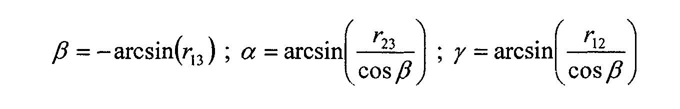
Das Auswerteverfahren wird nochmals unter Bezugnahme auf Fig. 16 erläutert:The evaluation method is described again with reference to Fig. 16 explains:
Zunächst werden in einem Schritt 35 die Koordinaten
Die Schritte 35 und 36 erfolgen vor einer Serie aufeinanderfolgender
Messungen, so daß die entsprechende aufwendige
Rechenarbeit nicht während der Meßserie und der Auswertung
einzelner Messungen erfolgen muss.
Eine Messung beginnt in einem Schritt 37 mit der Ermittlung
der neun Abstände d1, ..., d9.A measurement begins in a
Es wird in einem Schritt 38 sodann der Vektor L errechnet und
der Vektor
40 werden sodann die Translationen x, y, z und die Rotationswinkel
α, β, γ bestimmt. Dies bedeutet, daß dann sowohl die
Position als auch die Orientierung des Werkzeugs 16 bezüglich
der Werkstückhalterung 3 ermittelt ist.The translations x, y, z and the rotation angles then become 40
α, β, γ determined. This means that both the
Position as well as the orientation of the
Nach Abschluss des Schrittes 40 wird mit einer erneuten Abstandsmessung
in Schritt 37 fortgefahren.After
In Fig. 4 ist schematisch ein Interferometersystem 41 zur Bestimmung
der Abstände d1,...,d9 dargestellt. Dieses umfasst
eine Weißlichtquelle 43, welche beispielsweise durch eine
Superlumineszenzdiode gebildet sein kann. Im Hinblick auf
eine höhere Strahlungsintensität ist es jedoch bevorzugt,
hierfür eine Faserlichtquelle einzusetzen, welche durch eine
optisch gepumpte Lichtleitfaser bereitgestellt ist, die derart
dotiert ist, daß darin verstärkte spontane Emission
stattfindet. Eine solche Faserlichtquelle kann beispielsweise
unter der Produktbezeichnung WLS-02 von der Firma AMS Technologies-Optotec
Division, 82152 Martinsried/München bezogen
werden. Es ist jedoch auch möglich, als Lichtquelle 43 einen
Kurzpulslaser, wie etwa einen Femtosekunden-Laser, wie etwa
einen Titan-Saphir-Laser einzusetzen. Das von der Quelle 43
emittierte Licht wird über eine Lichtleitfaser 45 einem
Faserkoppler 47 zugeführt, welcher das Licht einerseits einem
Messzweig 49 und andererseits einem Referenzzweig 51 zuführt.
Dem Messzweig 49 wird das Licht über einen Faserleiter 53 von
dem Faserkoppler 47 her zugeführt, wobei durch den Rechner 67
ein steuerbarer optischer Umschalter 55 vorgesehen ist, der
das Licht wahlweise einer der Emitter-Empfänger-Baugruppen
18, 18', 18" zuführt. Die Emitter 18, 18', 18" senden ihr
Licht jeweils in Raumwinkel derart aus, daß das ausgesendete
Licht die drei Reflektoren 19, 19', 19" trifft und von diesen
zurück zu den Emitter-Empfänger-Baugruppen reflektiert wird.
Das von diesen wiederum empfangene Licht wird über den Lichtleiter
53 wieder dem Faserkoppler 47 zugeführt. 4 schematically shows an
In dem Referenzzweig 51 wird das Licht von dem Faserkoppler
47 durch einen Lichtleiter 57 einer Vorrichtung 60 zur Bereitstellung
eines änderbaren optischen Wegs g zugeführt. Die
Vorrichtung umfasst eine vor dem Ende der Faser 47 angeordnete
Kollimationsoptik 59, welche das zugeführte Licht auf
einen Spiegel 61 richtet, der mit einem änderbaren Abstand g
von der Kollimationsoptik 59 angeordnet ist. Das von dem
Spiegel 61 zurückgeworfene Licht wird durch die Optik 59
wieder in die Lichtleitfaser 47 eingekoppelt und wiederum dem
Faserkoppler 47 zugeführt.In the
Der Faserkoppler überlagert das durch die Fasern 53 und 57
aus dem Messzweig 49 bzw. Referenzzweig 59 zugeführte Licht
und gibt dieses über eine Lichtleitfaser 63 an einen
Strahlungssensor 65 aus.The fiber coupler overlays this with the
Wenn eine optische Weglänge des Messzweigs 59 mit der optischen
Weglänge des Referenzzweigs 51 übereinstimmt, registriert
der Strahlungssensor 65 eine erhöhte Strahlungsintensität.
Die optische Weglänge des Messzweigs 59 ist gegeben
durch die optische Weglänge zwischen dem Faserkoppler 47
und einem der Reflektoren 19, 19', 19". Die optische Weglänge
in dem Referenzzweig 51 ist gegeben durch die optische Weglänge
zwischen dem Faserkoppler 57 und dem Spiegel 61.If an optical path length of the measuring
In dem Messzweig 49 sind meist neun verschiedene optische
Weglängen bereitgestellt, die den neun Abständen zwischen den
Emitter-Empfänger-Baugruppen 18', 18', 18" und den drei Reflektoren
19, 19', 19" entsprechen. Durch kontinuierliches
Ändern der Länge g über den zur Verfügung stehenden Bereich
können dann neunmal durch den Sensor 65 Intensitätserhöhungen
festgestellt werden. Der Rechner 67 kann aus der Länge g, bei
der eine entsprechende Intensitätserhöhung stattfindet, dann
den Abstand zwischen einem entsprechenden Paar aus Emitter-Empfänger-Baugruppe
und Retroreflektor ermitteln. Hierbei ist
es zunächst nicht unbedingt klar, zwischen welchem Paar aus
Emitter-Empfänger-Baugruppe und Retroreflektor dieser Abstand
realisiert ist. Es ist allerdings möglich, daß weitere
Kenntnisse, wie beispielsweise eine vorangehend bereits bestimmte
Position und Orientierung der Baugruppen 18 und Reflektoren
19 als zusätzliche Information bekannt sind. Es ist
jedoch auch möglich, durch Betätigen des Umschalters 55 die
Strahlung lediglich einer der Emitter-Empfänger-Baugruppen
zuzuführen und/oder durch Betätigen der LCD-Verschlüsse 28 in
den Retroreflektoren lediglich einen derselben zu aktivieren,
so das eine von dem Sensor 65 registrierte Intensitätserhöhung
genau einem Paar von Emitter-Empfänger-Baugruppen
und Reflektoren zuzuordnen ist. Sowohl der Umschalter 55 als
auch die LCD-Verschlüsse 28 sind von dem Rechner 67 gesteuert.
Der Rechner 67 steuert auch einen Antrieb zur Änderung
der Länge g in dem Referenzzweig 51, weshalb dem Rechner 67
sämtliche Informationen zugänglich sind, um die Abstände
d1,...,d9 zu ermitteln. Aus diesen bestimmt der Rechner dann
nach dem vorangehenden in Zusammenhang mit Fig. 16 erläuterten
Verfahren die Position und Orientierung der Emitter-Empfänger-Baugruppen
18 und Reflektoren 19 relativ zueinander.In the measuring
Nachfolgend werden Varianten des in Zusammenhang mit Fig. 4 erläuterten Interferometersystems dargestellt. Hierbei sind ihrer Funktion einander entsprechende Komponenten mit den Bezugszahlen der Figuren 1 bis 4 versehen, zu unterscheiden jedoch durch einen zusätzlichen Buchstaben ergänzt. Zur Erläuterung wird auf die gesamte vorangehende Beschreibung Bezug genommen.Variants of the in connection with FIG. 4 illustrated interferometer system. Here are components corresponding to one another with the reference numbers of Figures 1 to 4 provided, however, to distinguish supplemented by an additional letter. In order to explain will refer to the entire foregoing description taken.
Ein in Fig. 6 gezeigtes Interferometersystem 41a umfasst eine
Weißlichtquelle 43a, deren Strahlung durch einen Lichtleiter
45a einem Faserkoppler 47a zugeführt wird, der die Strahlung
über einen Lichtleiter 57a einem Referenzzweig 51a zuführt.
In dem Referenzzweig 51a ist eine Vorrichtung 60a zur Bereitstellung
einer änderbaren optischen Weglänge angeordnet. An
Die Vorrichtung 60a umfasst eine Kollimationsoptik 59a, die
die an dem Ende der Faser 57a austretende Strahlung durch
eine halbdurchlässige Platte 71 auf einen Spiegel 61a richtet,
durch den die Strahlung zurück in die Faser 57a reflektiert
wird. Ein Abstand g zwischen der halbdurchlässigen
Platte 71 und dem Spiegel 61a ist durch einen Antrieb 73 änderbar,
welcher von einem Rechner 67a angesteuert wird. Allerdings
wird die von dem Ende der Faser 57a emittierte
Strahlung durch den halbdurchlässigen Spiegel 71a in zwei
Teilstrahlen aufgeteilt. Diese sind ein erster Teilstrahl,
der von dem halbdurchlässigen Spiegel 71a unmittelbar zurück
in die Faser 57a reflektiert wird. Der zweite Teilstrahl
durchsetzt den halbdurchlässigen Spiegel 71a und durchläuft,
im Unterschied zu dem ersten Teilstrahl, eine zusätzliche
Weglänge von zweimal g, bevor der zweite Teilstrahl nach Reflexion
an dem Spiegel 61a in die Faser 57a eingekoppelt
wird. Somit weist die in der Faser 57a zu dem Faserkoppler
47a zurücklaufende Strahlung eine Kohärenzstruktur derart
auf, daß mit dem Abstand 2*g voneinander angeordnete Wellenzüge
zueinander kohärent sind.The
Der Faserkoppler 47a führt die von dem Referenzzweig 51a zurückkommende
Strahlung einem Messzweig 49a über einen Lichtleiter
74 und einen weiteren Faserkoppler 75 zu. Nach dem
Faserkoppler 75 ist in dem Referenzzweig 49a ein Umschalter
55a vorgesehen, um die Strahlung durch Lichtleiter 77 Emitter-Empfänger-Baugruppen
18, 18', 18" zuzuführen, welche die
Strahlung hin zu in Fig. 6 nicht dargestellten Retroreflektoren
emittieren. Die von den Retroreflektoren zurückgeworfene
Strahlung wird wiederum in die Emitter-Empfänger-Baugruppen
18a eingekoppelt und über den Faserkoppler 75 und
eine Lichtleitfaser 79 einem Strahlungssensor 65a zugeführt,
dessen Meßsignal über eine Leitung 81 dem Rechner 67a zur
Verfügung gestellt wird. The fiber coupler 47a guides the one coming back from the
In dem Messzweig 49a verläuft somit die von den Retroreflektoren
zurückgeworfene Strahlung zurück zu dem Faserkoppler 75
und trifft auf den Detektor 65a. Zusätzlich zu der von den
Retroreflektoren zurückgeworfenen Strahlung entsteht auch
noch ein hin zu dem Detektor 65a verlaufender weiterer
Strahlungsanteil, der durch eine Spiegelung an Enden 78, 78'
78" der Fasern 77, 77' bzw. 77" erzeugt wird. Somit entsteht
zwischen einem Teilstrahl, der in dem Messzweig 49a durch die
Reflexion an dem Faserende 78 erzeugt wird und einem weiteren
Teilstrahl, der durch die Reflexion an dem Retroreflektor erzeugt
wird, eine feste Kohärenzbeziehung, ähnlich wie dies
für die beiden Teilstrahlen in Zusammenhang mit der Vorrichtung
60a bereits beschrieben wurde. Wenn nun die optische
Weglänge zwischen dem Faserende 78 und dem Retroreflektor und
zurück gleich der optischen Weglänge 2*g ist, wie sie durch
die Vorrichtung 60a bereitgestellt ist, registriert der
Strahlungssensor 65a ein Intensitätsmaximum. Hierüber ist der
Abstand zwischen dem entsprechenden Faserende 78 bzw. der
Emitter-Empfänger-Baugruppe 18a unmittelbar bestimmbar.The retroreflectors thus run in the measuring
In Fig. 6 ist ebenfalls ein durch den Rechner 67a gesteuerter
Umschalter 55a dargestellt, um die Strahlung selektiv einer
der Emitter-Empfänger-Baugruppen 18a, 18a und 18a zuzuführen.
Alternativ ist es jedoch ebenfalls möglich, in dem
Strahlengang zwischen den Emitter-Empfänger-Baugruppen und
den Retroreflektoren ein Chopperrad 81 vorzusehen, welches
durch einen durch den Rechner 67a gesteuerten Motor 83 um
eine Achse 85 drehbar derart angeordnet ist, daß ein Flügel
86 des Chopperrads 81 wahlweise die von der Emitter-Empfänger-Baugruppe
18a oder der Emitter-Empfänger-Baugruppe
18a' emittierte Strahlung unterbricht.6 is also one controlled by the
Ein in Fig. 7 dargestelltes Interferometersystem 41b ist, so
wie es dargestellt ist, zusammen mit der in Fig. 2 dargestellten
Anordnung aus einer Emitter-Empfänger-Baugruppe 18
und drei Retroreflektoren geeignet die Position zweier Objekte
relativ zueinander zu bestimmen, wobei in Fig. 7 lediglich
ein Retroreflektor 19 dargestellt ist. Es ist jedoch
einfach möglich, das Interferometersystem 41b derart abzuwandeln,
daß es drei Emitter-Empfänger-Baugruppen aufweist und
zur Bestimmung ebenfalls der relativen Orientierung zweier
Objekte geeignet ist, wie dies in Fig. 3 dargestellt ist.An
Das Interferometersystem 41b umfasst wiederum eine Weißlichtquelle
43b, wobei diese ihre Strahlung dem restlichen System
über einen optischen Isolator 84 zuführt, um die Quelle 43b
vor durch das System zurück zu dieser zurückreflektierter
Strahlung zu schützen.The
Über eine Glasfaser 45b und eine Kollimationsoptik 59b wird
die von der Quelle 43b emittierte Strahlung einer Vorrichtung
60b zur Bereitstellung einer änderbaren optischen Weglänge
zugeführt, welche, im Unterschied zu der in Fig. 6 dargestellten
Vorrichtung, nicht in Reflexion sondern in Transmission
arbeitet. Hierzu umfasst die Vorrichtung 60b zwei
halbdurchlässige Spiegel 71b und 72, deren Abstand g voneinander
motorisch änderbar ist. Durch die beiden Spiegel 71a
und 72 wird die Strahlung in zwei Teilstrahlen aufgeteilt,
nämlich einen Teilstrahl, der die beiden Spiegel 71a und 72
unmittelbar durchsetzt und durch eine weitere Optik 87 in
einen Lichtleiter 74b eingekoppelt wird, der die Strahlung
weiter zu einem Messzweig 51b führt. Ein zweiter Teilstrahl
durchsetzt zunächst den Spiegel 71b, wird an dem Spiegel 72
reflektiert, verläuft zurück zu dem Spiegel 71b, wird von
diesem erneut reflektiert, durchläuft dann den Spiegel 72 und
wird über die Optik 87 in die Faser 74b eingekoppelt. Im
Unterschied zu dem ersten Teilstrahl weist der zweite Teilstrahl
eine Verzögerung auf, welche der optischen Weglänge
2*g entspricht.Via a
Der weitere Aufbau des in Fig. 7 gezeigten Interferometersystems
41b ist weitgehend ähnlich dem des in Fig. 6 gezeigten
Interferometersystems, es werden nämlich die beiden Teilstrahlen
über einen Faserkoppler 57b und eine Lichtleitfaser
77b einer Emitter-Empfänger-Baugruppe 18b zugeführt, von der
sie zu den Reflektoren 19b hin emittiert wird. Von den
Reflektoren 19b zurückgeworfene Strahlung wird wieder in die
Faser 77b eingekoppelt und über einen Lichtleiter 79b einem
Strahlungssensor 65b zugeführt.The further structure of the interferometer system shown in FIG. 7
41b is largely similar to that shown in FIG. 6
Interferometer system, namely the two partial beams
via a fiber coupler 57b and an
Die Emitter-Empfänger-Baugruppe 18b umfasst ferner eine an
das Ende der Faser 77b angekoppelte GRIN-Linse, um die
Strahlung in den notwendigen Raumwinkel zu emittieren. Eine
Austrittsfläche 90 der Linse 89 ist teilweise verspiegelt, um
daran einen Rückreflex zu erzeugen, welcher unmittelbar zurück
auf den Sensor 65b geleitet wird. Der Sensor 65b erfasst
dann ein erhöhtes Intensitätsignal, wenn die Länge g zwischen
den Spiegel 71b, 72 der Vorrichtung 60b mit dem Abstand d
zwischen der Austrittsfläche 90 der Faser 77b und dem Mittelpunkt
des Reflektors 19b im wesentlichen zusammenfällt.The emitter-
Fig. 9 zeigt einen Verlauf 153 eines Meßsignals I, wie es der
Strahlungssensor 65b in Abhängigkeit von dem Abstand g der
Spiegel 71b und 72 voneinander ausgibt, wobei angenommen ist,
daß der Abstand d zwischen Reflektorkugel 19b und Emitter-Empfänger-Baugruppe
18b konstant ist. Sind die Abstände d und
g identisch (g-d=0), so ergibt sich ein maximales Interferenzsignal
I. Beidseits dieses Maximums bei g-d=0 fällt das
Meßsignal oszillierend ab.Fig. 9 shows a
Um den Abstand d genau zu messen, ist nun der Abstand g zu
suchen, an dem das Interferenzsignal maximal ist. Dies kann
zum einen dadurch erfolgen, daß die mit gestrichelter Linie
in Fig. 9 eingetragene Einhüllende 151 an das Meßsignal 153
ausgewertet wird und deren Maximum gesucht wird. Diese Vorgehensweise
ist meistens ausreichend, um den Abstand d mit
einer ausreichenden Genauigkeit messen zu können. In order to measure the distance d exactly, the distance g is now too
search at which the interference signal is at a maximum. This can
on the one hand in that the dashed
Ein genaueres, allerdings rechenintensiveres Verfahren sieht
vor, mehrere Maxima 155 und Minima 157 der Meßkurve 153 zu
lokalisieren, um daraus den Nullpunkt der Horizontalachse in
Fig. 9, d.h. die exakte Lage des Intensitätsmaximums aufzufinden.
Dies ist beispielsweise dann möglich, wenn der Nullpunkt
als Mittelwert aus den beiden tiefsten Minima 157 und
den drei höchsten Maxima 155 ermittelt wird. Auch andere Auswertungstechniken
zur Auffindung des Nullpunktes aus dem Verlauf
153 sind denkbar.A more precise, but more computationally intensive process is seen
before,
Ein in Fig. 8 dargestelltes Interferometersystem 41c weist im
wesentlichen den gleichen Aufbau auf, wie das in Fig. 7 dargestellte
Interferometersystem. Im Unterschied hierzu wird
die aus einem Messzweig 51c zurückkommende Strahlung jedoch
über einen Strahlungsteil 75c und eine daran angeschlossene
Lichtleitfaser 79c nicht unmittelbar einem Fotosensor 65c
zugeführt. Es wird vielmehr die in der Lichtleitfaser 79c in
Richtung zu dem Detektor 65c verlaufende Strahlung durch
einen weiteren Strahlteiler 93 auf zwei Lichtleitfasern 94
und 95 aufgeteilt, deren Faserenden 96 und 97 mit einem vorbestimmten
Abstand a voneinander angeordnet sind und die in
ihnen geführte Strahlung zu dem Fotodetektor 65c hin emittieren,
welcher hier als ein ortsauflösender Zeilendetektor
ausgebildet ist und mit Abstand von den Faserenden 96, 97
angeordnet ist. Von den Faserenden 96 und 97 wird die
Strahlung jeweils als Kugelwelle in einem Konus 98 und 99 auf
den Zeilendetektor 65 emittiert, wobei zwischen den Faserenden
96 bzw. 97 und dem Detektor 65c eine parallel zu der
Zeilenrichtung des Detektors 65c orienterte Zylinderlinse 100
angeordnet ist, um die Strahlung in einer Richtung quer zu
Zeilenrichtung des Detektors auf diesen zu fokussieren.An
Der Rechner 76c erfasst über die Datenleitung 81c die Orte,
an denen Intensitätsmaxima bzw. Intensitätsminima auf dem
Zeilendetektor 65c entstehen. The computer 76c acquires the locations via the
Sind die Länge g der Vorrichtung 60c zum Bereitstellen der
änderbaren optischen Weglänge und der Abstand d zwischen der
Emitter-Empfänger-Baugruppe 18c und dem Retroreflektor 19c
genau gleich, entsteht auf dem Detektor 65c ein Intensitätsmaximum
an einem Ort, der, bei identischer Länge der beiden
Fasern 94 und 95, symmetrisch zu den beiden Faserenden 96 und
97 angeordnet ist. Besteht jedoch zwischen der Länge g und
dem Abstand d ein kleiner Unterschied, so ist das entsprechende
Intensitätsmaximum von dem symmetrisch bezüglich der
Faserenden 96, 97 angeordneten Ort verlagert, wie dies mit
dem Ort X in Fig. 8 schematisch dargestellt ist. Die Größe
der Verlagerung weg von dem symmetrischen Ort ist dabei
weiter von dem Abstand a der beiden Faserenden 96, 97 voneinander
abhängig und ist um so grösser, je geringer der Abstand
zwischen den Faserenden 96, 97 ist.Are the length g of the
Sind die drei Retroreflektoren 19c mit unterschiedlichen Abständen
d von der Emitter-Empfänger-Baugruppe 18c angeordnet,
so entstehen auf dem Zeilendetektor 65c mehrere benachbart
zueinander angeordnete Intensitätsmaxima, welche gleichzeitig
von dem Rechner 67c erfasst werden können. Somit kann der
Rechner 67c ohne Änderung der Länge g und damit ohne Betätigung
des Antriebs der Vorrichtung 60c zur Bereitstellung
der änderbaren optischen Weglänge gleichzeitig die mehreren
Abstände d der Reflektoren von der Baugruppe 18 erfassen.Are the three
Es kann auch eine in Fig. 8 nicht dargestellte Vorrichtung
zur Halterung der Faserenden 96, 97 vorgesehen sein, bei welcher
der Abstand a von dem Rechner 67c motorisch gesteuert
änderbar ist. Weisen die verschiedenen Abstände d kleine Unterschiede
voneinander auf, so wird ein kleiner Abstand a
eingestellt, um die Auflösung der Abstandsmessung zu erhöhen.
Unterscheiden sich die verschiedenen Abstände d um größere
Werte voneinander, so daß die entsprechenden Intensitätsmaxima
bei dem kleinen Abstand a nicht gleichzeitig auf dem
Detektor 65c entstehen, so wird der Abstand a erhöht, um die
Abstände, bei verminderter Auflösung, gleichzeitig erfassen
zu können.A device not shown in FIG. 8 can also be used
be provided for holding the fiber ends 96, 97, in which
the distance a from the
Wie aus Fig. 1 ersichtlich ist, ist der Rechner 67 und ein
Großteil der Komponenten des Interferometersystems 41 neben
der Werkzeugmaschine 1 angeordnet. Lediglich ein Teil der Interferometeranordnung
41, nämlich deren Meßzweig, ist an der
Werkzeugmaschine 1 angeordnet, um die Meßstrahlung der
Emitter-Empfänger-Baugruppe 18 zuzuführen. Hierzu tritt die
Lichtleitfaser 53 in den fest mit dem Boden verbundenen
Sockel 7 der Werkzeugmaschine 1 ein. Von dort wird die
Strahlung dann ebenfalls mittels Lichtleiter durch den bewegbaren
Arm 9 bis hin zu der Emitter-Empfänger-Baugruppe 18
geführt. Hierbei tritt das Problem auf, daß bei der Strahlführung
in dem bewegten Arm 9 mittels herkömmlicher Ein-Moden-Lichtleiter
Bewegungen des Lichtleiters zu Änderungen
von dessen doppelbrechenden Eigenschaften führen, welche wiederum
polarisationsabhängig zu Änderungen der optischen Weglänge
in dem Lichtleiter führen. Da in solchen Situationen
bei derartigen Lichtleitern auch Änderungen des Polarisationszustands
des darin geführte Lichts auftreten, können bei
Durchlaufen des Lichtleiters in Richtung hin zu dem Emitter
und zurück von dem Empfänger derartige Phasenunterschiede
zwischen den beiden Polarisationsrichtungen auftreten, daß
sich das Licht des einen Polarisationszustands und das Licht
des anderen Polarisationszustands bei der späteren Verarbeitung
der Strahlung in der Interferometeranordnung sogar gegenseitig
zur Interferenz auslöschen können. Deshalb ist vorgesehen,
die Strahlung in dem bewegten Teil der Werkzeugmaschine
1 nicht in einem herkömmlichen Ein-Moden-Leiter zu
führen sondern hierzu einen polarisationserhaltenden Lichtleiter
einzusetzen.As can be seen from FIG. 1, the computer is 67 and
Most of the components of the
Dies ist schematisch in Fig. 10 dargestellt. Der mit gestrichelten
Linien dargestellte Kasten 1 symbolisiert die Werkzeugmaschine
1 als Ganzes, d.h. inklusive ihrer gegenüber den
restlichen Komponenten des Interferometersystems 41 bewegten
Teile, und der mit gestrichelten Linien dargestellte Kasten 7
symbolisiert den gegenüber den restlichen Teilen der Interferometeranordnung
41 ruhenden Sockel der Werkzeugmaschine 1.
Die Strahlung wird dem ruhenden Sockel 7 über den Lichtleiter
53 zugeführt. In dem Sockel 7 ist ein fest mit diesem verbundener
Faserkoppler 101 vorgesehen, der die über den Lichtleiter
53 zugeführte Strahlung in eine polarisationserhaltende
Faser 103 an deren einem Ende 102 einkoppelt. Die Faser
103 führt die Strahlung dann in dem bewegten Arm 9 der fest
mit einem Teil des bewegten Arms 9 verbundenen Emitter-Empfänger-Baugruppe
18 zu, die an das objektseitige Ende 105
der Faser 103 angekoppelt ist.This is shown schematically in FIG. 10. The one with dashed
Die Baugruppe 18 umfasst eine Kollimationsoptik 109, um einen
emittierten Strahl 111 zu formen. Vor der Kollimationsoptik
109 ist eine Viertelwellenplatte 113 angeordnet, die der
Strahl 111 nach Verlassen der Optik 109 durchläuft. Der
Strahl 111 wird an dem Reflektor 19 reflektiert, durchläuft
die Viertelwellenplatte 113 erneut und wird über die Kollimationsoptik
109 wieder in die polarisationserhaltende Faser
103 eingekoppelt. Die von dem Reflektor 9 zurückgeworfene
Strahlung durchläuft den Leiter 103, wird an der Schnittstelle
101 in die Faser 53 eingekoppelt und gelangt zu den
restlichen Komponenten des Interferometersystems 41 zur weiteren
Verarbeitung.The
Beim Eintritt in die polarisationshaltende Faser 103 an deren
Faserende 102 erfolgt eine Zerlegung des durch die Faser 53
zugeführten unpolarisierten Lichts in dessen beide Polarisationsrichtungen,
welche durch die Faser 103 in separaten
Polarisationskanälen bis zu dem anderen Faserende 105 transportiert
werden. Hierbei tritt ein Übersprechen von einem
Polarisationskanal zu dem anderen Polarisationskanal im
wesentlichen nicht auf. Eine durch einen ersten der beiden
Polarisationskanäle durch die Faser 103 transportierte
Strahlungskomponente erfährt auf Grund des zweimaligen Durchlaufens
der Viertelwellenplatte 113 eine vollständige Polarisationsdrehung,
so daß sie auf ihrem Rückweg durch die
Faser 103 deren anderen zweiten Polarisationskanal durchläuft.
Umgekehrt durchläuft die zweite Polarisationskomponente
des eintretenden Lichts auf dem Hinweg den anderen
zweiten Polarisationskanal zuerst und auf dem Rückweg dann
den ersten Polarisationskanal.When entering the polarization-maintaining
Beide Polarisationskomponenten der über den Lichtleiter 53
zugeführten umpolarisierten Strahlung durchlaufen somit nacheinander
zuerst den einen und dann den anderen Polarisationskanal.
Selbst wenn die beiden Polarisationskanäle jeweils unterschiedliche
optische Weglängen in dem polarisationserhaltenden
Lichtleiter 103 bereitstellen, so durchlaufen sie
in der Summe jedoch beide den im wesentlichen identischen gesamten
optischen Weg durch den Lichtleiter 103. Deshalb entstehen
auch im wesentlichen keine Phasenunterschiede zwischen
den beiden Polarisationskomponenten, und die vorangehend beschriebene
Signalauslöschung auf Grund solcher Phasenunterschiede
tritt bei dem Einsatz der polarisationserhaltenden
Faser 103 in den bewegten Teilen der Werkzeugmaschine 1 nicht
auf.Both polarization components of the
Das vorangehend im Zusammenhang mit einem Abstandssensor beschriebene Konzept des Einsatzes der polarisationserhaltenden Faser in einer Situation, in der die beiden Faserenden 102 und 105 relativ zueinander bewegt werden, ist nicht auf den Abstandssensor beschränkt. Es ist auch für andere Sensortypen einsetzbar, bei denen Licht über einen Lichtleiter einem Sensorkopf sowohl zugeführt als auch von diesem zur weiteren Auswertung zurückgeführt wird. Es kann sich hierbei um einen Sensor allgemeiner Art handeln, bei dem die zugeführte Strahlung mit irgendeinem geeigneten Medium, eine Oberfläche oder einem Probenvolumen in Wechselwirkung tritt, eine Änderung der Strahlungseigenschaften erfährt, welche sodann, nach Zurückführung der Strahlung durch den selben Lichtleiter, analysiert werden. Es kann dies beispielsweise ein Drucksensor, ein Spannungssensor, ein Temperatursensor ein Sensor für elektrische oder magnetische Felder oder ein Sensor sein, der das Vorhandensein von Chemikalien oder ähnlichem erfasst.The previously described in connection with a distance sensor Concept of using the polarization-maintaining Fiber in a situation where the two fiber ends 102 and 105 are moved relative to each other is not on the Distance sensor limited. It is also for other types of sensors can be used where light is transmitted through a light guide to a sensor head both fed and from this to the other Evaluation is returned. It can be a Act sensor of a general type, in which the supplied Radiation with any suitable medium, a surface or a sample volume interacts, a change which experiences radiation properties, which then after returning the radiation through the same light guide, to be analyzed. For example, it can be a Pressure sensor, a voltage sensor, a temperature sensor Sensor for electrical or magnetic fields or a sensor be the presence of chemicals or the like detected.
Weiter ist dieses Konzept auch auf Strahl Zu- und Abführungen
anwendbar, bei denen der strahlungszuführende bzw.
strahlungsabführende Lichtleiter 103 nicht lediglich
Bewegungen unterworfen ist. Es gibt nämlich auch andere
Umwelteinflüsse, welche bei der herkömmlichen Ein-Moden-Faser
zu Signalstörungen führen. Dies sind beispielsweise Druck,
Temperatur, starke elektrische oder magnetische Felder,
chemische Einflüsse und dergleichen. Auch gegenüber
derartigen Umwelteinflüssen ist die polarisationserhaltende
Faser 103 weitgehend stabil. Somit ist dieses Konzept auch
einsetzbar, wenn ein optischer Sensor eingesetzt wird, wobei
der strahlungszuführende bzw. -abführende Lichtleiter ein
Umfeld durchsetzt, welches auf Grund von Einflüssen wie
Temperatur, Druck und ähnlichem die Signalübertragung
beeinflussen würde.This concept is also applicable to beam inlets and outlets
applicable where the radiation supply or
radiation-dissipating light guides 103 not only
Is subject to movements. Because there are also others
Environmental influences, which with the conventional single-mode fiber
lead to signal interference. For example, this is pressure,
Temperature, strong electric or magnetic fields,
chemical influences and the like. Also opposite
Such environmental influences are polarization-maintaining
Fig. 11 zeigt eine Vorrichtung zum Bereitstellen einer änderbaren
optischen Weglänge bzw. zum Bereitstellen einer änderbaren
optischen Verzögerung ("Optical delay") in Form eines
Riemenscanners 201 in Draufsicht. Fig. 12 zeigt eine teilweise
Seitenansicht des Riemenscanners 201. Der Riemenscanner
201 umfasst zwei Riemenscheiben 203 und 204 mit jeweils
gleichen Durchmessern D und Drehachsen 205 bzw. 206, welche
parallel zueinander und mit einem Abstand e voneinander angeordnet
sind. Die oberen Stirnseiten der beiden Scheiben 203,
204 liegen in einer gemeinsamen Ebene, und um die Umfangsflächen
der beiden Scheiben ist ein Ringriemen 209 geführt.
Die Länge des Ringriemens 209 und der Abstand e der beiden
Scheibenachsen 205 und 206 sind derart aufeinander abgestimmt,
daß der Riemen 209 in seiner Umfangsrichtung unter
mechanischer Spannung steht und somit fest an den Umfangsflächen
der Scheiben 203, 204 anliegt. Die Scheibe 203 ist
durch einen in Fig. 11 nicht dargestellten Antrieb, wie etwa
ein Motor, in einer Richtung 213 um ihrer Drehachse 205 antreibbar,
so daß ebenfalls der Riemen 209 und die andere
Scheibe 204 in die gleiche Richtung angetrieben werden.11 shows a device for providing a changeable
optical path length or to provide a changeable
Optical delay in the form of a
Ein Arbeitsbereich 215 des Riemenscanners 201 ist in einem
Bereich des Riemens gebildet, in welchem dieser sich geradlinig
von der Scheibe 203 zur Scheibe 204 in Richtung 213 erstreckt.
In diesem Bereich erstreckt sich der Riemen entlang
einer Tangente, die den Umfangsflächen der Scheiben 203 und
204 gemeinsam ist.A
An dem Riemen 209 sind vier Spiegelanordnungen 217 festgemacht,
welche in Umfangsrichtung des Riemens 209 mit jeweils
gleichem Abstand voneinander angeordnet sind. In der
Darstellung der Fig. 11 ist eine mit 217 bezeichnete
Spiegelanordnung im Arbeitsbereich 215 angeordnet. Außer
dieser Spiegelanordnung 217 sind keine weiteren Spiegelanordnungen
217 in dem Arbeitsbereich angeordnet.Four
Neben der Riemenscheibe 204 ist eine Halterung 219 fest bezüglich
der Drehachsen 205, 206 angeordnet und trägt eine
Strahlführungseinrichtung 221 sowie eine Spiegelanordnung
223.In addition to the
Der Strahlführungseinrichtung 221 wird mittels eines Lichtleiters
225 die Strahlung einer Lichtquelle zugeführt. Die
Strahlführungseinrichtung 221 enthält eine in den Figuren 11,
12 nicht dargestellte Kollimationsoptik, um einen parallelisierten
Lichtstrahl 227 parallel zur Richtung des Riemens 209
in dem Arbeitsbereich 215 derart zu emittieren, daß er die in
dem Arbeitsbereich 215 angeordnete Spiegelanordnung 217
trifft. An der Spiegelanordnung 217 trifft der Strahl 227
zunächst auf einen unter 45° zur Richtung des Strahls 227 angeordneten
Spiegel 229, der den Strahl 227 um 90° umlenkt und
auf einen weiteren Spiegel 231 lenkt, der mit dem Spiegel 229
einen Winkel von 90° einschließt. Die beiden Spiegel 229 und
231 wirken als ein Reflektor 233, der den Strahl 227 parallel
zu dessen ursprünglichen Strahlrichtung, jedoch in eine Richtung
233 parallel zu dieser versetzt, derart zurückwirft, daß
er auf die bezüglich der Strahlführungseinrichtung 221 festangeordnete
Spiegelanordnung 223 trifft. Die Richtung 233 ist
orthogonal zu der Bewegungsrichtung 213 des Riemens 209 in
dem Arbeitsbereich 215 und parallel zu der Oberfläche des
Riemens 209 in dem Arbeitsbereich 215 orientiert.The
Der Strahl 235 trifft an der Spiegelanordnung 223 zunächst
auf einen durch zwei Spiegelflächen 237 und 239 gebildeten
Reflektor 241, welcher den Strahl 235 um ein weiteres Stück
in die Richtung 233 versetzt zu der Spiegelanordnung 217 zurückwirft,
wo der Strahl 243 durch einen weiteren Reflektor
245, der ebenfalls zwei unter 90° zueinander angeordnete
Spiegelflächen umfasst, als ein Strahl 247 wieder in Richtung
zu der Spiegelanordnung 223 zurückreflektiert wird. Dort
trifft der Strahl 247 auf einen weiteren durch zwei Spiegelflächen
gebildeten Reflektor 249, der den Strahl 247 nochmal
parallel versetzt und umlenkt und als Strahl 251 in Richtung
zu der Reflektoranordnung 217 lenkt. Dort trifft der Strahl
251 auf einen Retroreflektor 253, welcher aus drei paarweise
orthogonal zueinander angeordneten Spiegelflächen aufgebaut
ist damit den Strahl 251 genau in sich selbst zurückwirft.
Der von dem Retroreflektor 253 in sich selbst zurückgeworfene
Strahl trifft dann nacheinander auf die Reflektoren 249, 245,
241 und 231, woraufhin er durch die Kollimationsoptik der
Strahlführungseinrichtung 221 wieder in die Lichtfaser 225
eingekoppelt wird.The
Aufgrund der mehrfachen Hin- und Her-Reflexion zwischen der
an dem Riemen 209 angebrachten Spiegelanordnung 217 und der
fest angebrachten Spiegelanordnung 223 durchläuft der Strahl
zwischen seiner Emission durch die Strahlführungseinrichtung
221 und seinen erneuten Eintritt in dieselbe einen optischen
Weg, der etwas mehr als dem Zehnfachen des Abstands c entspricht,
mit dem die beiden Spiegelanordnungen 217 und 223
voneinander angeordnet sind.Due to the multiple back and forth reflection between the
on the
Bewegt sich die Spiegelanordnung in 217 von dem Beginn des
Arbeitsbereichs 215 bis zu dessen Ende, so ändert sich die
optische Weglänge des Strahls zwischen Austritt und Eintritt
aus bzw. in die Strahführungseinrichtung 221 um einen Wert,
der dem Zehnfachen der Länge des Arbeitsbereichs 215 entspricht.The mirror assembly moves in 217 from the beginning of the
Der maximale Hub, d.h. die maximale Änderung der optischen
Weglänge, des Riemenscanners 201 weist demnach ein Wert auf,
der dem Zehnfachen des Abstands e der beiden Achsen 205 und
206 voneinander entspricht.The maximum stroke, i.e. the maximum change in optical
Path length of the
Ist die Spiegelanordnung 217 im Arbeitsbereich 215 angeordnet,
so weist die Spiegelanordnung 217 , welche bei Bewegung
des Riemens 209 in Richtung 213 als nächstes in den Arbeitsbereich
215 gelangt, einen solchen Abstand auf, daß die
Spiegelanordnung 217 genau dann im Arbeitsbereich angeordnet
ist, wenn die vorauslaufende Spiegelanordnung 217 diesen gerade
verlassen hat. Eine solche Situation ist in Fig. 11 mit
gestrichelter Linie dargestellt, wobei die Spiegelanordnung
217, wenn sie den Arbeitsbereich 215 gerade verlassen hat,
mit dem Bezugszeichen 257 bezeichnet ist und die Spiegelanordnung
217 unmittelbar nach ihrem Eintreten in den Arbeitsbereich
215 mit dem Bezugszeichen 258 bezeichnet ist.If the
Bei Bewegung der Spiegelanordnung 217 in Richtung 213 bewegt
sich diese nach Verlassen des Arbeitsbereichs 215 entlang
einer Kreisbahn um die Scheibe 204. Dies bedeutet, daß
während einer gewissen Zeitdauer die Spiegelanordnung 217
zwar den Arbeitsbereich 215 verlassen hat, jedoch den Strahl
227 noch geometrisch abschattet, so daß die Strahlführung in
dem optischen Scanner 201 unterbrochen ist. Während dieser
Zeit kann der optische Scanner 201 keine optische Weglänge
bereitstellen. Dies ist gewissermassen eine Totzeit, die den
Tastgrad der Vorrichtung 201 kleiner als 1 macht. Diese Totzeit
kann allerdings dazu verwendet werden, um eine Elektronik,
die eine Auswertung des verzögerten optischen Signals
vornimmt, zurückzusetzen oder andere Umschaltungen vorzunehmen.Moved in the
Sobald die Spiegelanordnung 217 dann weit genug um die Umfangsfläche
der Scheibe 204 bewegt ist, gibt die Spiegelanordnung
217 den Strahl 227 wieder frei, so daß dieser auf
die der Spiegelanordnung 217 nachlaufende Spiegelanordnung
217 trifft und von dieser genau so reflektiert wird, wie
dies vorangehend bereits für die Spiegelanordnung 217 beschrieben
wurde.Once the
Um im Hinblick auf die wenigstens aufgrund der Abschattung
entstehende Totzeit möglichst den gesamten zur Verfügung
stehenden Hub, d.h. die maximale änderbare optische Weglänge
nutzen zu können, ist der Abstand zwischen in Umfangsrichtung
des Bands 209 aufeinanderfolgenden Spiegelanordnungen 217
etwas größer eingestellt als der zur Verfügung stehende Hub.
Dies erfolgt bei den in den Figuren 11 und 12 dargestellten
Riemenscanner 201 dadurch, daß der Durchmesser D der Riemenscheiben
203, 204 zu 165 mm gewählt ist und das Verhältnis
der Achsabstände e zu Scheibendurchmesser e/D zu 1,34 gewählt
ist.To with regard to at least due to shadowing
resulting dead time, if possible, the entire available
standing stroke, i.e. the maximum changeable optical path length
To be able to use is the distance between in the circumferential direction
of the
Das Band 209 ist in der beschriebenen Ausführungsform ein
Stahlband aus Invar-Stahl, d.h. einem Stahl, der einen geringen
thermischen Ausdehnungskoeffizienten aufweist. Ferner ist
an dem Scanner 201 noch wenigstens eine mit 210 bezeichnete
Führungseinrichtung vorgesehen, welche das Band wenigstens in
axialer Richtung der Scheiben 203, 204 führt, so daß es sich
in einer stabilen Lage um die Scheiben 203, 204 bewegt. Der
Antrieb treibt die Riemenscheibe 203 mit einer solchen Geschwindigkeit
an, daß sich das Band mit einer Geschwindigkeit
von 10 Meter pro Sekunde in Umfangsrichtung 213 bewegt.The
In den Figuren 13 und 14 ist eine Variante für eine Vorrichtung
zum Bereitstellen einer änderbaren optischen Weglänge
dargestellt, welche als Spiralscanner 301 ausgebildet ist.FIGS. 13 and 14 show a variant for a device
to provide a changeable optical path length
shown, which is designed as a
Dem Spiralscanner 301 wird ein Lichtstrahl 303 zugeführt,
welcher zunächst einen ersten polarisierenden Strahlteiler
305 und sodann einen zweiten polarisierenden Strahlteiler 307
jeweils geradlinig durchläuft. Nach Durchlaufen einer
Viertelwellenplatte 309 trifft der Strahl dann auf einen
bezüglich der beiden Strahlteiler fest angeordneten Spiegel
311, welcher den Strahl etwa um 90° ablenkt, so daß er
parallel zu einer Drehachse 313 verläuft. Nach Reflexionen an
dem Spiegel 311 durchläuft der Strahl noch eine
Kollimationslinse 315, welche den Strahl derart formt, daß er
als Parallelstrahl auf der Drehachse 313 und in Figur 13in
Richtung nach oben weiterverläuft.A
Der Spiralscanner 301 umfasst weiter eine Baugruppe 316, welche
aus den folgenden mit fester räumlicher Beziehung zueinander
angeordneten Komponenten aufgebaut ist, nämlich einem
Umlenkspiegel 317, einem Planspiegel 319 und einer Zylinderlinse
321. Die Baugruppe 316 ist als Einheit um die Achse 313
rotierbar angeordnet, wobei sie durch einen in den Figuren 13
und 14 nicht dargestellten Antrieb in Drehung versetzt wird.The
Der Spiralscanner 301 umfasst weiterhin einen Spiralspiegel
323, dessen Spiegelfläche sich spiralförmig um die Drehachse
313 erstreckt. The
Der Umlenkspiegel 317 der rotierenden Baugruppe 316 ist derart
auf der Drehachse 313 angeordnet, daß er den die Kollimationslinse
315 verlassenden Strahl um 90° und auf die
Spiegelfläche des Spiralspiegels 323 lenkt, wobei der Strahl
zwischen seiner Umlenkung an dem Umlenkspiegel 317 und seinem
Auftreffen auf dem Spiralspiegel 323 noch die Zylinderlinse
321 durchläuft. Nach Auftreffen auf dem Spiralspiegel 323
wird der Strahl hin zu dem Planspiegel 319 der rotierenden
Baugruppe 316 reflektiert, welcher immer orthogonal zu dem
auf ihn treffenden Strahl ausgerichtet ist, so daß er den
Strahl in sich selbst zurück auf den Spiralspiegel 323 wirft.
Von diesem wird der Strahl dann nach erneutem Durchlaufen der
Zylinderlinse 321 zurück auf den Umlenkspiegel 317 reflektiert,
welcher den Strahl dann auf der Drehachse 313 nach unten
verlaufend orientiert. Der zurücklaufende Strahl durchsetzt
dann die Kollimationslinse 315, wird von dem Spiegel
311 umgelenkt, durchläuft die Viertelwellenplatte 309 und
wird dann von dem polarisierenden Strahlteiler 307 um 90° abgelenkt,
trifft auf einen weiteren 90°-Umlenkspiegel 325,
durchsetzt eine Strahlformungsbaugruppe 327, wird von einem
weiteren 90°-Umlenkspiegel 329 dem polarisierenden Strahlteiler
305 zugeführt, welcher den zurücklaufenden Strahl dann
so ausrichtet, daß er im wesentlichen kolinear zu dem einfallenden
Strahl 303 verläuft.The
Je nach Drehstellung der Baugruppe 316 stellt der Spiralscanner
301 eine unterschiedliche optische Weglänge bereit.
Dies ist in Fig. 14 nochmals erläutert: Diese zeigt zwei
Drehstellungen der rotierenden Baugruppe, wobei der Planspiegel
319 in der einen Drehstellung mit 319 und in der
anderen Drehstellung mit 319 bezeichnet ist.Depending on the rotational position of
Die Gestalt des Spiralspiegels 323 ist als eine logarithmische
Spirale gewählt, so daß in Abhängigkeit von einem Umfangswinkel
ϕ der Abstand der Spiegelfläche von der Drehachse
313 folgende Gleichung genügt:
Hierbei ist cot ψ konstant, so daß auch der Winkel ψ konstant
ist. Der Winkel ψ ist in Fig. 13 dargestellt und beschreibt
den Winkel zwischen den auf den Spiralspiegel 323 treffenden
Strahl und einer Tangente 335 an die Spirale des Spiegels
323.Here cot ψ is constant, so that the angle ψ is also constant
is. The angle ψ is shown in Fig. 13 and describes
the angle between those striking the
Da der Winkel ψ unabhängig von der Drehstellung der Baugruppe
316 um die Drehachse 313 ist, trifft der Strahl immer unter
dem gleichen Winkel auf die Oberfläche des Spiralspiegels 323
und wird damit auch immer um den gleichen Winkel abgelenkt.Because the angle ψ is independent of the rotational position of the
Der Winkel zwischen dem auf den Spiralspiegel 323 treffenden
Strahl und dem von diesem zurückgeworfenen Strahl ist mit R
bezeichnet und ist ebenfalls unabhängig von der Drehstellung.
Dies bedeutet weiter, daß der von dem Spiralspiegel 323 reflektierte
Strahl auch unabhängig von der Drehstellung immer
unter einem gleichem Winkel von 90° auf den Planspiegel 319
fällt, da dieser derart ausgerichtet ist, daß der auf ihn
treffende Strahl in sich selbst zurück reflektiert wird.
Durch die Wahl der Spiegelgestalt als Spiralspiegel ist somit
gewährleistet, daß der in den Scanner 301 eintretende Strahl
im wesentlichen in sich zurückreflektiert wird.The angle between that striking the
Da der auf den Spiralspiegel 323 treffende Strahl eine gewisse
Ausdehnung quer zu seiner Strahlrichtung aufweist und
die Fläche des Spiralspiegels 323 nicht orthogonal zu dieser
Strahlrichtung orientiert ist, erfährt der Strahl zwischen
Eintritt und Austritt in den Spiralscanner 301 eine optische
Weglänge, die nicht über den ganzen Strahlquerschnitt genau
konstant ist. Aus diesem Grund ist auch die Strahlformungsbaugruppe
327 vorgesehen, um hieraus resultierende Effekte zu
begrenzen. Die Strahlformungsbaugruppe 327 umfasst eine Zerstreuungslinse
339, eine Lochblende 341 und eine fokussierende
Linse 343.Since the beam striking the
Die rotierende Baugruppe 316 ist dynamisch ausgewuchtet, so
daß sie selbst bei hohen Umdrehungsgeschwindigkeiten und damit
schnellen Änderungen der optischen Weglänge einen ruhigen
und präzisen Lauf aufweist.The
Die vorangehend beschriebenen Vorrichtungen 201 und 301 zum
Bereitstellen einer änderbaren optischen Weglänge sind in jeder
möglichen Anwendung einsetzbar, bei der eine änderbare
optische Weglänge bzw. eine einstellbare optische Verzögerung
bereitgestellt werden soll. Insbesondere kommt hier ein Einsatz
in einem Interferometer und weiter bevorzugt in einem
Weißlicht-Interferometer in Frage. Bevorzugterweise werden
die Vorrichtungen 201 und 203 auch in dem System zum Bestimmen
der Position oder/und Orientierung zweier Objekte eingesetzt,
wie es vorangehend im Zusammenhang mit den Figuren 1
bis 10 erläutert wurde.The
Fig. 15 zeigt eine Variante der in Fig. 1 gezeigten Werkzeugmaschine.
Hier ist eine Fertigungsstrasse 401 zur Herstellung
eines Automobils 403 schematisch dargestellt. Hinsichtlich
ihres Aufbaus und ihrer Funktion einander entsprechende Komponenten
sind mit den Bezugszahlen der Figuren 1 bis 10 bezeichnet,
zusätzlich jedoch mit einem ergänzenden Buchstaben
versehen. Zur Erläuterung wird jeweils auf die gesamte vorangehende
Beschreibung Bezug genommen.FIG. 15 shows a variant of the machine tool shown in FIG. 1.
Here is a
Das zu bearbeitende Werkstück ist hierbei das Automobil 403
welches auf einer Werkstückhalterung 3d, welche auch Schienen
405 umfasst, durch die Fertigungsstrasse 401 bewegt wird. Zur
Bearbeitung des Werkstücks sind vier Werkzeugmaschinen 1d
vorgesehen, welche mit ihren Werkzeugen 16d jeweils Bearbeitungen
an dem Werkstück 403 vornehmen. Die Werkzeuge 16d
werden durch die jeweilige Werkzeugmaschine 1d in einem vergleichsweise
grossen Volumen bewegt. Jedes Werkzeug 16d weist
drei Emitter-Empfänger-Baugruppen auf, welche allerdings in
Fig. 15 nicht dargestellt sind. Diese dienen zur Bestimmung
sowohl der Position als auch der Orientierung der Werkzeuges
16d bezüglich der Werkstückhalterung 3d. Das zugehörige Meßsystem
umfasst entsprechend eine Mehrzahl von Platten 20d,
welche fest mit der Werkstückhalterung 3d über Träger 21d
verbunden sind. Eine jede der Platten 20d trägt drei Retroreflektoren
19d, welche, wie in Fig. 1 dargestellt, Strahlen
zurück zu den Emitter-Empfänger-Baugruppen reflektieren, die
an den Werkzeugen 16d angebracht sind. Allerdings arbeitet
die Emitter-Empfänger-Baugruppe an einem jeden Werkzeug 16d
nicht mit lediglich einer Retroreflektorengruppe 20d zusammen
sondern hat hierfür eine Mehrzahl solcher Retroreflektorengruppen
zur Auswahl, welche an vorbestimmten bekannten Positionen
an den Halterungen 21d angebracht sind. Es kannn
sich nun, je nach momentaner Position des Werkzeugs 16d in
dem zugänglichen Arbeitsvolumen, herausstellen, das eine genauere
Bestimmung von Position und Orientierung des Werkzeugs
16d bezüglich der Werkstückhalterung 3 möglich ist, indem für
die Abstandsbestimmung eine bestimmte Reflektorengruppe 20d
ausgewählt wird, welche günstig relativ zu dem Werkzeug 16d
angeordnet ist.The workpiece to be machined is the
Aufgrund der Vielzahl der um die Werkzeugmaschinen 1d angeordneten
Reflektorenbaugruppen 20d befindet sich immer eine
Reflektorenbaugruppe 20d im Blickfeld einer jeden Emitter-Empfänger-Baugruppe,
so daß eine Abstandsbestimmung für das
entsprechende Werkzeug 16d mit ausreichender Präzision möglich
ist.Due to the large number of arranged around the
In den vorangehenden Ausführungsbeispielen wurde jeweils eine
Emitter-Empfänger-Baugruppe beschrieben, um die beiden Funktionen
Aussenden der Strahlung in den Raumwinkelbereich hin
zu den Retroreflektoren und Empfangen der von den Retroreflektoren
zurückreflektierten Strahlung zu erfüllen. Es ist
jedoch auch möglich, für die beiden Funktionen jeweils separate
Komponenten vorzusehen. So ist es beispielsweise möglich,
die Fig. 3 dargestellte Ausführungsform derart abzuwandeln,
daß im Zentrum der Platte 31 lediglich ein Emitter
vorgesehen ist, und daß die in Fig. 3 mit den Bezugszeichen
18, 18 und 18 bezeichneten Komponenten Empfänger für die
Strahlung sind. Auch dann ist es möglich, die neun Abstände
zwischen den Komponenten 18, 18 und 18 einerseits und den
drei Retroreflektoren 19, 19 und 19 andererseits zu bestimmen.In the previous exemplary embodiments, one was in each case
Emitter-receiver assembly described the two functions
Emission of the radiation in the solid angle range
to the retroreflectors and receiving those from the retroreflectors
to reflect back reflected radiation. It is
however also possible, separate for the two functions
To provide components. For example, it is possible
to modify the embodiment shown in FIG. 3 in such a way
that in the center of the
Umgekehrt ist es jedoch auch möglich, daß die in Fig. 3 mit
18, 18 und 18 bezeichneten Komponenten jeweils Emitter
sind, die mit festem Abstand zueinander angeordnet sind, und
daß zentral in der Platte 31 ein einziger Empfänger vorgesehen
ist, um die neun benötigten Abstände zu bestimmen.Conversely, it is also possible that the in Fig. 3 with
Bei der in den Figuren 11 und 12 dargestellten Ausführungsform
ist als umlaufender Riemen 209 ein Stahlband eingesetzt.
Es ist jedoch auch möglich, andere Materialien für den umlaufenden
Riemen auszuwählen. Beispiele sind hier Kunststoffe
und faserverstärkte Kunststoffe, Gummi usw.In the embodiment shown in Figures 11 and 12
a steel belt is used as the
Die Führung des Riemens bezüglich der Riemenscheiben erfolgt bei der Ausführungsform gemäß den Figuren 11 und 12, wie beschrieben, durch ein oder mehrere den Riemen wenigstens teilweise umgreifende Führungen. Es ist jedoch auch möglich, daß der Riemen ein solches Querschnittsprofil aufweist, welches Vorsprünge oder Ausnehmungen oder ähnliches aufweist, welche mit an den Umfangsflächen der Scheiben vorgesehenen Ausnehmungen und Vorsprüngen so korrespondiert, daß diese ineinander eingreifen und damit eine Führung des Riemens unmittelbar an der Umfangsfläche der Scheiben möglich ist. Ein Beispiel hierfür wäre die Ausführung des Riemens als Keilrippenriemen mit einem Rippenprofil, wie es beispielsweise in der deutschen Industrie Norm DIN 7867 beschrieben ist. The belt is guided with respect to the pulleys in the embodiment according to FIGS. 11 and 12, as described, by one or more of the straps at least partially comprehensive tours. However, it is also possible that the belt has such a cross-sectional profile which Has projections or recesses or the like, which with recesses provided on the peripheral surfaces of the disks and projections correspond so that they interlock intervene and thus direct the belt is possible on the peripheral surface of the disks. An example the belt would be designed as a V-ribbed belt with a rib profile, such as in the German Industry standard DIN 7867 is described.
Vorangehend wurde das System bzw. das Verfahren zum Bestimmen der Position und/oder der Orientierung zweier Objekte relativ zueinander in einer Anwendung auf einer Werkzeugmaschine beschrieben, wobei die beiden Objekte das Werkzeug einerseits und die Werkstückhalterung andererseits sind und wobei die Reflektoren an der Werkstückhalterung angebracht sind. Es ist jedoch auch möglich, die Reflektoren auf Seiten des Werkzeugs und die Emitter bzw. Empfänger auf Seiten der Werkstückhalterung anzubringen. Ferner ist es möglich, das System bzw. das Verfahren auf jegliche andere Paare von Objekten anzuwenden, zwischen denen Abstände bzw. Orientierungen zu bestimmen sind. Insbesondere ist hier ein Koordinatenmeßgerät ins Auge gefasst, mit dem die Oberfläche eines Werkstücks abgetastet wird. Das Werkstück kann auch hier, ähnlich wie bei der Werkzeugmaschine, auf einer Werkstückhalterung angeordnet sein. Ein Tastkopf mit einer Tastspitze zur Antastung der Oberfläche des Werkstücks kann entweder durch eine Mechanik getragen sein, ähnlich wie das Werkzeug der Werkzeugmaschine, wobei es entweder motorisch oder durch die Führung per Hand durch einen Benutzer entlang der Werkstückoberfläche bewegt wird. Es ist jedoch auch möglich, daß der Tastkopf alleine von der Hand des Benutzers getragen wird und frei von diesem entlang der Werkstückoberfläche bewegt wird. Es sind dann entweder an dem Tastkopf die Emitter und die Empfänger angebracht, während die Retroreflektoren an der Werkstückhalterung angebracht sind, oder es sind die Retroreflektoren an dem Tastkopf angebracht während die Emitter und Empfänger an der Werkstückhalterung angebracht sind.The system or the method for determining was previously the position and / or the orientation of two objects relative described to each other in an application on a machine tool, the two objects being the tool on the one hand and the workpiece holder, on the other hand, and wherein the Reflectors are attached to the workpiece holder. It is however, the reflectors on the side of the tool are also possible and the emitter or receiver on the part of the Attach the workpiece holder. It is also possible that System or procedure on any other pair of To use objects between which distances or Orientations are to be determined. In particular, here is one Coordinate measuring device envisaged with which the surface of a workpiece is scanned. The workpiece can too here, similar to the machine tool, on one Workpiece holder can be arranged. A probe with one Probe tip for probing the surface of the workpiece can either be carried by a mechanism, similar to that Tool of the machine tool, being either motor or by guiding by hand by a user the workpiece surface is moved. However, it is also possible that the probe alone by the user's hand is worn and free of this along the Workpiece surface is moved. Then it's either at that Probe attached while the emitter and receiver the retroreflectors are attached to the workpiece holder or are the retroreflectors on the probe attached while the emitter and receiver are attached to the Workpiece holder are attached.
Claims (40)
dadurch gekennzeichnet, daß
eine bezüglich der Strahlführungseinrichtung (221) fest angeordnete zweite Spiegelanordnung (223) vorgesehen ist und
die erste und die zweite Spiegelanordnung (217, 223) derart ausgebildet sind, daß der Lichtstrahl zwischen seinem Austritt aus der Strahlführungseinrichtung (221) und Eintritt in diese wenigstens ein Mal zwischen der ersten und der zweiten Spiegelanordnung (217, 223) hin und her reflektiert wird.Apparatus for providing a changeable optical path length for a light beam, comprising:
characterized in that
a second mirror arrangement (223) fixedly arranged with respect to the beam guiding device (221) is provided and
the first and the second mirror arrangement (217, 223) are designed such that the light beam reflects back and forth between the first and the second mirror arrangement (217, 223) at least once between its exit from the beam guiding device (221) and entry into it becomes.
wobei die zweite Spiegelanordnung (223) wenigstens einen Reflektor (241, 249) aufweist, der bezüglich der Strahlführungseinrichtung (221) in der zu der Tangente orthogonalen Richtung (233) mit Abstand versetzt angeordnet ist.The device according to claim 28, wherein the first mirror arrangement (217) has at least two reflectors (231, 245, 253) which are arranged at a distance from one another in a direction orthogonal to the tangent, and
wherein the second mirror arrangement (223) has at least one reflector (241, 249) which is arranged offset with respect to the beam guiding device (221) in the direction orthogonal to the tangent (233).
dadurch gekennzeichnet, daß
in dem zentralen Bereich ein drehfest bezüglich der Strahlführungseinrichtung (317) positionierter zweiter Spiegel (319) derart vorgesehen ist, daß der Lichtstrahl nach einer Reflexion an dem ersten Spiegel (323) auf den zweiten Spiegel (319) trifft und von diesem zurück auf den ersten Spiegel (323) reflektiert wird.Apparatus for providing a changeable optical path length for a light beam, comprising:
characterized in that
In the central area, a second mirror (319), which is non-rotatably positioned with respect to the beam guiding device (317), is provided in such a way that the light beam strikes the second mirror (319) after reflection from the first mirror (323) and from there back to the first Mirror (323) is reflected.
Applications Claiming Priority (2)
| Application Number | Priority Date | Filing Date | Title |
|---|---|---|---|
| DE10118392 | 2001-04-13 | ||
| DE10118392A DE10118392A1 (en) | 2001-04-13 | 2001-04-13 | System and method for determining a position and / or orientation of two objects relative to one another as well as beam guidance arrangement, interferometer arrangement and device for changing an optical path length for use in such a system and method |
Related Child Applications (2)
| Application Number | Title | Priority Date | Filing Date |
|---|---|---|---|
| EP11005596.9 Division-Into | 2011-07-08 | ||
| EP11005597.7 Division-Into | 2011-07-08 |
Publications (3)
| Publication Number | Publication Date |
|---|---|
| EP1251328A2 true EP1251328A2 (en) | 2002-10-23 |
| EP1251328A3 EP1251328A3 (en) | 2002-11-27 |
| EP1251328B1 EP1251328B1 (en) | 2013-04-03 |
Family
ID=7681446
Family Applications (1)
| Application Number | Title | Priority Date | Filing Date |
|---|---|---|---|
| EP02008409A Expired - Lifetime EP1251328B1 (en) | 2001-04-13 | 2002-04-12 | System and method for determining the position or/and the orientation of two objects relative to each other, as well as beam guidance device, interferometer system and device for modifying the optical pathlength for use in such a system and method |
Country Status (5)
| Country | Link |
|---|---|
| US (1) | US7358516B2 (en) |
| EP (1) | EP1251328B1 (en) |
| JP (2) | JP4280456B2 (en) |
| CA (1) | CA2381687C (en) |
| DE (1) | DE10118392A1 (en) |
Cited By (4)
| Publication number | Priority date | Publication date | Assignee | Title |
|---|---|---|---|---|
| WO2011029811A1 (en) * | 2009-09-10 | 2011-03-17 | Carl Zeiss Ag | Device, method, and reflector arrangement for determining position |
| WO2011036033A1 (en) * | 2009-09-23 | 2011-03-31 | Carl Zeiss Ag | Method and device for determining the orientation and position of an object |
| CN102575926A (en) * | 2009-09-10 | 2012-07-11 | 卡尔蔡司股份公司 | Devices and methods for determining positions and measuring surfaces |
| EP3273200A1 (en) * | 2016-07-22 | 2018-01-24 | Etalon AG | Measuring system for the measurement of lengths and/or changes in length |
Families Citing this family (64)
| Publication number | Priority date | Publication date | Assignee | Title |
|---|---|---|---|---|
| DE10260256B9 (en) * | 2002-12-20 | 2007-03-01 | Carl Zeiss | Interferometer system and measuring / machining tool |
| WO2006102997A1 (en) | 2005-03-30 | 2006-10-05 | Carl Zeiss Smt Ag | Method of manufacturing an optical element |
| US7499772B2 (en) * | 2005-08-31 | 2009-03-03 | Honeywell International Inc. | Method and system for navigating a nondestructive evaluation device |
| EP1970666B8 (en) * | 2007-03-14 | 2013-01-09 | Thales Alenia Space Italia S.p.A. | Interferometer |
| DE102008003282B4 (en) | 2008-01-05 | 2010-07-01 | µ-GPS OPTICS GMBH | Arrangement and method for determining a position of two objects relative to each other |
| DE102008045387B4 (en) | 2008-09-02 | 2017-02-09 | Carl Zeiss Ag | Apparatus and method for measuring a surface |
| DE102008045386B4 (en) | 2008-09-02 | 2017-07-13 | Carl Zeiss Ag | Device and method for determining an object position |
| US9482755B2 (en) | 2008-11-17 | 2016-11-01 | Faro Technologies, Inc. | Measurement system having air temperature compensation between a target and a laser tracker |
| US8209134B2 (en) * | 2008-12-04 | 2012-06-26 | Laura P. Solliday | Methods for modeling the structural health of a civil structure based on electronic distance measurements |
| US10203268B2 (en) | 2008-12-04 | 2019-02-12 | Laura P. Solliday | Methods for measuring and modeling the process of prestressing concrete during tensioning/detensioning based on electronic distance measurements |
| US7905031B1 (en) * | 2009-03-06 | 2011-03-15 | Florida Turbine Technologies, Inc. | Process for measuring a part |
| DE102009017491A1 (en) * | 2009-04-15 | 2010-11-11 | Kuka Roboter Gmbh | System and method for measuring a manipulator |
| DE102009024464B4 (en) | 2009-06-10 | 2017-09-21 | Carl Zeiss Ag | Evaluation device, measuring arrangement and method for path length measurement |
| DE102009028068B4 (en) * | 2009-07-29 | 2023-05-25 | Dr. Johannes Heidenhain Gmbh | position measuring device |
| TWI480513B (en) | 2009-12-04 | 2015-04-11 | Raydium Semiconductor Corp | Optical coherence tomography apparatus and operating method thereof |
| US9400170B2 (en) | 2010-04-21 | 2016-07-26 | Faro Technologies, Inc. | Automatic measurement of dimensional data within an acceptance region by a laser tracker |
| US8619265B2 (en) | 2011-03-14 | 2013-12-31 | Faro Technologies, Inc. | Automatic measurement of dimensional data with a laser tracker |
| US9772394B2 (en) | 2010-04-21 | 2017-09-26 | Faro Technologies, Inc. | Method and apparatus for following an operator and locking onto a retroreflector with a laser tracker |
| US9377885B2 (en) | 2010-04-21 | 2016-06-28 | Faro Technologies, Inc. | Method and apparatus for locking onto a retroreflector with a laser tracker |
| DE102010039945B4 (en) * | 2010-08-30 | 2012-04-19 | Carl Zeiss Ag | Methods and devices for position determination |
| DE102010039947A1 (en) | 2010-08-30 | 2012-03-01 | Carl Zeiss Ag | Methods and devices for position determination |
| DE102010039948B4 (en) | 2010-08-30 | 2020-10-22 | Carl Zeiss Ag | Measuring unit, measuring system and method for determining a relative position and relative orientation |
| JP5491435B2 (en) * | 2011-02-25 | 2014-05-14 | キヤノン株式会社 | Measuring device |
| GB2518769A (en) | 2011-03-03 | 2015-04-01 | Faro Tech Inc | Target apparatus and method |
| US9164173B2 (en) | 2011-04-15 | 2015-10-20 | Faro Technologies, Inc. | Laser tracker that uses a fiber-optic coupler and an achromatic launch to align and collimate two wavelengths of light |
| US9482529B2 (en) | 2011-04-15 | 2016-11-01 | Faro Technologies, Inc. | Three-dimensional coordinate scanner and method of operation |
| US9686532B2 (en) | 2011-04-15 | 2017-06-20 | Faro Technologies, Inc. | System and method of acquiring three-dimensional coordinates using multiple coordinate measurement devices |
| WO2012141868A1 (en) | 2011-04-15 | 2012-10-18 | Faro Technologies, Inc. | Enhanced position detector in laser tracker |
| CN104094081A (en) | 2012-01-27 | 2014-10-08 | 法罗技术股份有限公司 | Inspection method with barcode identification |
| DE102012101640B4 (en) | 2012-02-29 | 2013-10-31 | Carl Zeiss Ag | Method and system for determining a position and orientation of an object in a reference system |
| GB201205563D0 (en) * | 2012-03-29 | 2012-05-09 | Sec Dep For Business Innovation & Skills The | Coordinate measurement system and method |
| DE102012017015B4 (en) * | 2012-08-20 | 2015-03-19 | Luphos Gmbh | Method and device for the high-precision measurement of surfaces |
| US9558555B2 (en) * | 2013-02-22 | 2017-01-31 | Leap Motion, Inc. | Adjusting motion capture based on the distance between tracked objects |
| CZ308920B6 (en) * | 2013-03-11 | 2021-09-01 | České vysoké učení technické v Praze | Method and device for redundant optical measurement and / or calibrating the position of a body in space |
| US9733715B2 (en) | 2013-03-15 | 2017-08-15 | Leap Motion, Inc. | Resource-responsive motion capture |
| US9041914B2 (en) | 2013-03-15 | 2015-05-26 | Faro Technologies, Inc. | Three-dimensional coordinate scanner and method of operation |
| US9632572B2 (en) | 2013-10-03 | 2017-04-25 | Leap Motion, Inc. | Enhanced field of view to augment three-dimensional (3D) sensory space for free-space gesture interpretation |
| US9074869B2 (en) * | 2013-12-11 | 2015-07-07 | Faro Technologies, Inc. | Method for measuring 3D coordinates of a spherically mounted retroreflector from multiple stations |
| US9423492B2 (en) | 2013-12-11 | 2016-08-23 | Faro Technologies, Inc. | Method for finding a home reference distance using a spherically mounted retroreflector |
| US9347767B2 (en) | 2013-12-11 | 2016-05-24 | Faro Technologies, Inc. | Spherically mounted retroreflector and method to minimize measurement error |
| US9121689B2 (en) | 2013-12-11 | 2015-09-01 | Faro Technologies, Inc. | Method for correcting a spherically mounted retroreflector when resetting a distance meter |
| US9329028B2 (en) | 2013-12-11 | 2016-05-03 | Faro Technologies, Inc. | Spherically mounted retroreflector having an embedded temperature sensor and socket |
| US8947678B2 (en) * | 2013-12-11 | 2015-02-03 | Faro Technologies, Inc. | Method for correcting three-dimensional measurements of a spherically mounted retroreflector |
| US9239238B2 (en) | 2013-12-11 | 2016-01-19 | Faro Technologies, Inc. | Method for correcting a 3D measurement of a spherically mounted retroreflector on a nest |
| DE102013113949B4 (en) * | 2013-12-12 | 2021-03-18 | Deutsches Zentrum für Luft- und Raumfahrt e.V. | Manufacturing facility |
| JP6331587B2 (en) * | 2014-03-31 | 2018-05-30 | 株式会社東京精密 | Three-dimensional coordinate measuring apparatus and method, and calibration apparatus |
| US9395174B2 (en) | 2014-06-27 | 2016-07-19 | Faro Technologies, Inc. | Determining retroreflector orientation by optimizing spatial fit |
| DE102014014220A1 (en) * | 2014-09-20 | 2016-03-24 | Laserscanning Europe Gmbh | Reference sphere for use in laser measuring technology, in particular as a spherical target for terrestrial laser scanning |
| WO2016183339A1 (en) | 2015-05-12 | 2016-11-17 | Hexagon Metrology, Inc. | Apparatus and method of controlling a coordinate measuring machine using environmental information or coordinate measuring machine information |
| US10203192B2 (en) | 2015-05-29 | 2019-02-12 | Hexagon Metrology, Inc. | CMM with object location logic |
| JP2017019072A (en) * | 2015-07-14 | 2017-01-26 | トヨタ自動車株式会社 | Position measurement system |
| DE102015119274B4 (en) * | 2015-11-09 | 2018-07-12 | Björn Habrich | Method and device for determining the spatial position of an object by means of interferometric length measurement |
| JP6341546B2 (en) * | 2016-02-24 | 2018-06-13 | Necプラットフォームズ株式会社 | Light energy time division distribution device, plant factory, building, light energy time division distribution method and rotating cylinder |
| DE102017103455A1 (en) | 2017-02-20 | 2018-08-23 | Etalon Ag | Measuring system for measuring lengths and / or changes in length |
| CN106441152B (en) * | 2016-10-18 | 2019-02-01 | 淮阴师范学院 | Asymmetric optical interferometry method and device |
| US10473451B2 (en) * | 2017-08-07 | 2019-11-12 | Apre Instruments, Inc. | Measuring the position of objects in space |
| DE102018222629A1 (en) | 2018-01-17 | 2019-07-18 | Carl Zeiss Industrielle Messtechnik Gmbh | Method and device for determining at least one spatial position and orientation of at least one object |
| JP6954624B2 (en) | 2018-02-05 | 2021-10-27 | 日本電気株式会社 | Sensor device |
| DE102018220088A1 (en) | 2018-11-22 | 2020-05-28 | Carl Zeiss Industrielle Messtechnik Gmbh | Method and device for determining at least one spatial position and orientation of at least one measurement object |
| DE102019134939A1 (en) * | 2019-12-18 | 2021-06-24 | Carl Zeiss Industrielle Messtechnik Gmbh | Device for detecting a position of a body |
| DE102020110995A1 (en) | 2020-04-22 | 2021-10-28 | Carl Zeiss Industrielle Messtechnik Gmbh | Coordinate measuring machine |
| DE102020110994B4 (en) | 2020-04-22 | 2023-03-23 | Carl Zeiss Industrielle Messtechnik Gmbh | Coordinate measuring machine for three-dimensional measurement of coordinates of a workpiece |
| DE102020111509B4 (en) | 2020-04-28 | 2023-04-20 | Carl Zeiss Industrielle Messtechnik Gmbh | Coordinate measuring device and method for measuring coordinates of a workpiece |
| WO2023102309A1 (en) * | 2021-12-02 | 2023-06-08 | Plx, Inc. | Self-aligning active retroreflector system and method |
Citations (8)
| Publication number | Priority date | Publication date | Assignee | Title |
|---|---|---|---|---|
| US3597091A (en) * | 1968-01-18 | 1971-08-03 | Itek Corp | Interferometer |
| US4621926A (en) * | 1985-04-30 | 1986-11-11 | Lasercon Corporation | Interferometer system for controlling non-rectilinear movement of an object |
| WO1988007656A1 (en) * | 1987-03-21 | 1988-10-06 | Renishaw Plc | Interferometer position measurement system |
| SU1739165A1 (en) * | 1990-05-30 | 1992-06-07 | И. А. Муханов и А. Д. Муханов | Decorative luminaire |
| US5214279A (en) * | 1990-07-26 | 1993-05-25 | Fuji Photo Film Co., Ltd. | Scanning microscope and tuning fork scanning mechanism for varying the width over which a sample is scanned |
| WO1993022637A1 (en) * | 1992-05-05 | 1993-11-11 | Tabarelli, Werner | Interferometer |
| US5808740A (en) * | 1995-08-31 | 1998-09-15 | Sokkia Company Limited | Multiaxis distance measurement device for NC machine tools |
| DE10015242A1 (en) * | 1999-03-29 | 2000-10-05 | Ando Electric | Optical part drive unit and optical interferometer |
Family Cites Families (48)
| Publication number | Priority date | Publication date | Assignee | Title |
|---|---|---|---|---|
| FR2104671B1 (en) | 1970-06-26 | 1973-05-25 | Cit Alcatel | |
| JPS578407A (en) | 1980-06-20 | 1982-01-16 | Yokokawa Kyoryo Seisakusho:Kk | Reflector |
| US4457625A (en) * | 1981-07-13 | 1984-07-03 | Itek Corporation | Self calibrating contour measuring system using fringe counting interferometers |
| US4533242A (en) * | 1982-09-28 | 1985-08-06 | The United States Of America As Represented By The Administrator Of The National Aeronautics And Space Administration | Ranging system which compares an object-reflected component of a light beam to a reference component of the light beam |
| US4494821A (en) | 1983-03-07 | 1985-01-22 | Polaroid Corporation | Laser printing system with developable helicoid reflector |
| DE3334460A1 (en) * | 1983-09-23 | 1985-04-11 | Fa. Carl Zeiss, 7920 Heidenheim | MULTI-COORDINATE MEASURING MACHINE |
| JPS60129614A (en) | 1983-12-19 | 1985-07-10 | Omron Tateisi Electronics Co | Potentiometer |
| DE3585758D1 (en) | 1984-07-18 | 1992-05-07 | Philips Nv | Interferometer. |
| US5267143A (en) * | 1984-10-12 | 1993-11-30 | Sensor Adaptive Machines, Incorporated | Vision assisted fixture construction |
| GB2180117B (en) | 1985-09-05 | 1989-09-06 | Ferranti Plc | Three-dimensional position measuring apparatus |
| US4824251A (en) | 1987-09-25 | 1989-04-25 | Digital Signal Corporation | Optical position sensor using coherent detection and polarization preserving optical fiber |
| US4884889A (en) | 1987-11-19 | 1989-12-05 | Brown & Sharpe Manufacturing Company | Calibration system for coordinate measuring machine |
| US4939678A (en) * | 1987-11-19 | 1990-07-03 | Brown & Sharpe Manufacturing Company | Method for calibration of coordinate measuring machine |
| JPH01203906A (en) * | 1988-02-10 | 1989-08-16 | Brother Ind Ltd | Optical fiber sensor device |
| FR2647560B1 (en) | 1989-05-23 | 1994-01-28 | Thomson Csf | DEVICE FOR READING POLARIMETRIC AND INTERFEROMETRIC SENSORS |
| US4932783A (en) | 1989-07-21 | 1990-06-12 | United States Of America As Represented By The Secretary Of The Navy | Apparatus and method for minimizing polarization-induced signal fading in an interferometric fiber-optic sensor using input-polarization modulation |
| JPH03130690A (en) | 1989-10-14 | 1991-06-04 | Nikon Corp | Optical communication apparatus for electro-optical distance measuring system |
| US5070483A (en) * | 1990-01-12 | 1991-12-03 | Shell Oil Company | Remote seismic sensing |
| US5007721A (en) | 1990-05-25 | 1991-04-16 | The United States Of America As Represented By The Secretary Of The Air Force | Mechanically rotated Doppler frequency shifter |
| IL95008A0 (en) | 1990-07-09 | 1991-06-10 | Scitex Corp Ltd | Scanning apparatus and method |
| JP2993082B2 (en) * | 1990-09-12 | 1999-12-20 | ブラザー工業株式会社 | Integrated optical interferometer |
| CH684212A5 (en) | 1990-10-16 | 1994-07-29 | Suisse Electronique Microtech | The optical white light interferometry. |
| US5465147A (en) | 1991-04-29 | 1995-11-07 | Massachusetts Institute Of Technology | Method and apparatus for acquiring images using a ccd detector array and no transverse scanner |
| WO1992019930A1 (en) | 1991-04-29 | 1992-11-12 | Massachusetts Institute Of Technology | Method and apparatus for optical imaging and measurement |
| US5220406A (en) * | 1991-09-27 | 1993-06-15 | Hughes Danbury Optical Systems, Inc. | Sample point interferometer having separate rigid body and figure measurement channels |
| GB9203471D0 (en) | 1992-02-19 | 1992-04-08 | Sensor Dynamics Ltd | Optical fibre pressure sensor |
| AT396526B (en) * | 1992-04-23 | 1993-10-25 | Tabarelli Werner | INTERFEROMETER |
| JPH05312953A (en) | 1992-05-06 | 1993-11-26 | Nec Corp | Optical ranging system |
| DE4224190B4 (en) * | 1992-07-22 | 2007-01-18 | Abb Research Ltd. | Fiber optic current sensor |
| US5455670A (en) | 1993-05-27 | 1995-10-03 | Associated Universities, Inc. | Optical electronic distance measuring apparatus with movable mirror |
| JPH07239272A (en) * | 1994-02-28 | 1995-09-12 | Ando Electric Co Ltd | Optical wavelength meter |
| JP2795613B2 (en) | 1994-06-07 | 1998-09-10 | 工業技術院長 | Measuring method of position and posture of moving object |
| US5491524A (en) | 1994-10-05 | 1996-02-13 | Carl Zeiss, Inc. | Optical coherence tomography corneal mapping apparatus |
| US6144456A (en) | 1995-05-04 | 2000-11-07 | Haag-Streit Ag | Apparatus having a multiple angle transparent rotating element for measuring the thickness of transparent objects |
| US6460004B2 (en) * | 1996-02-06 | 2002-10-01 | Perceptron, Inc. | Method and apparatus for calibrating a non-contact gauging sensor with respect to an external coordinate system |
| US5793483A (en) | 1996-02-07 | 1998-08-11 | Visidyne, Inc. | Optical measurement system |
| JP3657362B2 (en) * | 1996-07-16 | 2005-06-08 | 独立行政法人科学技術振興機構 | Optical pulse characteristic measuring apparatus and measuring method thereof |
| US5784186A (en) | 1996-12-04 | 1998-07-21 | National Science Council | Scanning optical delay device having a helicoid reflecting mirror |
| DE19705889C2 (en) * | 1997-02-15 | 1999-12-09 | Daimler Chrysler Ag | Angle of rotation sensor |
| JPH11183145A (en) * | 1997-10-15 | 1999-07-09 | Yuusuke Nonomura | Three-dimensional observation apparatus |
| US6057911A (en) | 1997-11-17 | 2000-05-02 | Northrop Grumman Corporation | Fiber optic fabry-perot sensor for measuring absolute strain |
| US6191862B1 (en) | 1999-01-20 | 2001-02-20 | Lightlab Imaging, Llc | Methods and apparatus for high speed longitudinal scanning in imaging systems |
| JP4151159B2 (en) * | 1999-06-17 | 2008-09-17 | 松下電器産業株式会社 | Medium measuring device |
| DE10028502A1 (en) | 1999-06-30 | 2001-01-04 | Zeiss Carl Fa | Interferometer has path length variation device that varies optical path length, deflects beam onto fixed reflector at inclined deflection surface, turns about axis to vary optical path length |
| US6201609B1 (en) | 1999-08-27 | 2001-03-13 | Zygo Corporation | Interferometers utilizing polarization preserving optical systems |
| DE19941796A1 (en) * | 1999-09-02 | 2001-03-22 | United Parts Fhs Automobil Sys | Automatic gear selector handle for vehicle, with button to move tie rod acting via connecting part against pivot joint |
| JP3501052B2 (en) | 1999-11-25 | 2004-02-23 | トヨタ自動車株式会社 | Image processing device for vehicles |
| DE10041041A1 (en) | 2000-08-22 | 2002-03-07 | Zeiss Carl | Interferometer device e.g. for eye surgery has beam guide which directs superimposed beam onto surfaces |
-
2001
- 2001-04-13 DE DE10118392A patent/DE10118392A1/en not_active Withdrawn
-
2002
- 2002-04-05 JP JP2002104061A patent/JP4280456B2/en not_active Expired - Fee Related
- 2002-04-10 US US10/120,253 patent/US7358516B2/en active Active
- 2002-04-12 EP EP02008409A patent/EP1251328B1/en not_active Expired - Lifetime
- 2002-04-12 CA CA2381687A patent/CA2381687C/en not_active Expired - Fee Related
-
2008
- 2008-10-01 JP JP2008256385A patent/JP2009036775A/en active Pending
Patent Citations (8)
| Publication number | Priority date | Publication date | Assignee | Title |
|---|---|---|---|---|
| US3597091A (en) * | 1968-01-18 | 1971-08-03 | Itek Corp | Interferometer |
| US4621926A (en) * | 1985-04-30 | 1986-11-11 | Lasercon Corporation | Interferometer system for controlling non-rectilinear movement of an object |
| WO1988007656A1 (en) * | 1987-03-21 | 1988-10-06 | Renishaw Plc | Interferometer position measurement system |
| SU1739165A1 (en) * | 1990-05-30 | 1992-06-07 | И. А. Муханов и А. Д. Муханов | Decorative luminaire |
| US5214279A (en) * | 1990-07-26 | 1993-05-25 | Fuji Photo Film Co., Ltd. | Scanning microscope and tuning fork scanning mechanism for varying the width over which a sample is scanned |
| WO1993022637A1 (en) * | 1992-05-05 | 1993-11-11 | Tabarelli, Werner | Interferometer |
| US5808740A (en) * | 1995-08-31 | 1998-09-15 | Sokkia Company Limited | Multiaxis distance measurement device for NC machine tools |
| DE10015242A1 (en) * | 1999-03-29 | 2000-10-05 | Ando Electric | Optical part drive unit and optical interferometer |
Cited By (4)
| Publication number | Priority date | Publication date | Assignee | Title |
|---|---|---|---|---|
| WO2011029811A1 (en) * | 2009-09-10 | 2011-03-17 | Carl Zeiss Ag | Device, method, and reflector arrangement for determining position |
| CN102575926A (en) * | 2009-09-10 | 2012-07-11 | 卡尔蔡司股份公司 | Devices and methods for determining positions and measuring surfaces |
| WO2011036033A1 (en) * | 2009-09-23 | 2011-03-31 | Carl Zeiss Ag | Method and device for determining the orientation and position of an object |
| EP3273200A1 (en) * | 2016-07-22 | 2018-01-24 | Etalon AG | Measuring system for the measurement of lengths and/or changes in length |
Also Published As
| Publication number | Publication date |
|---|---|
| CA2381687A1 (en) | 2002-10-13 |
| JP2009036775A (en) | 2009-02-19 |
| DE10118392A1 (en) | 2002-11-07 |
| US20020179866A1 (en) | 2002-12-05 |
| EP1251328A3 (en) | 2002-11-27 |
| US7358516B2 (en) | 2008-04-15 |
| JP2003014420A (en) | 2003-01-15 |
| CA2381687C (en) | 2013-10-22 |
| EP1251328B1 (en) | 2013-04-03 |
| JP4280456B2 (en) | 2009-06-17 |
Similar Documents
| Publication | Publication Date | Title |
|---|---|---|
| EP1251328A2 (en) | System and method for determining the position or/and the orientation of two objects relative to each other, as well as beam guidance device, interferometer system and device for modifying the optical pathlength for use in such a system and method | |
| EP3078983B1 (en) | Coordinate measuring device | |
| EP2458363B1 (en) | Measurement of the positions of curvature midpoints of optical areas of a multi-lens optical system | |
| EP2093537B1 (en) | Process and device for the determination of the alignment of two rotatable machine parts | |
| EP2558880B1 (en) | Coordinate measuring device with automated targeting | |
| DE4202505A1 (en) | Medical and surgical instrument, e.g. microscope, positioning system - uses optical transmitter e.g laser fixed to surgeons headband operating as steering system and positioning electronics to control support arm and microscope | |
| EP3797257B1 (en) | Oct system and oct method | |
| EP3642655A1 (en) | Device for determining an orientation of an optical device of a coherence tomograph, coherence tomograph and laser processing system | |
| DE102011012611B4 (en) | Method and device for non-contact measurement of an angle | |
| WO2005088241A1 (en) | Low-coherence interferometric method and appliance for scanning surfaces in a light-optical manner | |
| EP1292805A1 (en) | Measuring device for detecting the dimensions of test samples | |
| EP0791818B1 (en) | Method and device for photothermal testing a workpiece | |
| DE102008055486A1 (en) | Optical measuring arrangement and optical measuring method | |
| DE102016008184B4 (en) | Measuring device and method for monitoring a machining process for machining a workpiece under synchronous control of a machining scanner and a reference arm scanner and system for processing and monitoring a workpiece with a measuring device | |
| DE102011107451B3 (en) | Method and device for determining the position and orientation of a body | |
| EP3374732B1 (en) | Method and device for determining the spatial position of an object by means of interferometric length measurement | |
| DE102019002942A1 (en) | Measuring device and method for performing optical coherence tomography with a coherence tomograph | |
| EP1018631B1 (en) | Device to measure dimensions of objects and procedure to use same device | |
| EP1510779A1 (en) | Method for determining position coordinates | |
| DE102019116280B3 (en) | Method and apparatus for determining a length | |
| DE3808779A1 (en) | LASER INTERFEROMETRY MEASURING DEVICE | |
| EP0092504A2 (en) | Fibre-optic measuring device with a sensor and measuring electronics to determine position | |
| DE10252314B4 (en) | Detector system, interference measurement system and optical measurement method | |
| WO2009087061A1 (en) | Arrangement and method for determination of a position and/or orientation of two objects relative to one another | |
| DE4138562A1 (en) | Micro-profilometer measurement head - has two polarisation dividers for measurement and reference beams produced from single light source and measures distance or relative speed variations |
Legal Events
| Date | Code | Title | Description |
|---|---|---|---|
| PUAI | Public reference made under article 153(3) epc to a published international application that has entered the european phase |
Free format text: ORIGINAL CODE: 0009012 |
|
| PUAL | Search report despatched |
Free format text: ORIGINAL CODE: 0009013 |
|
| AK | Designated contracting states |
Kind code of ref document: A2 Designated state(s): AT BE CH CY DE DK ES FI FR GB GR IE IT LI LU MC NL PT SE TR |
|
| AX | Request for extension of the european patent |
Free format text: AL;LT;LV;MK;RO;SI |
|
| RIC1 | Information provided on ipc code assigned before grant |
Free format text: 7G 01B 11/00 A, 7G 01B 9/02 B |
|
| AK | Designated contracting states |
Kind code of ref document: A3 Designated state(s): AT BE CH CY DE DK ES FI FR GB GR IE IT LI LU MC NL PT SE TR |
|
| AX | Request for extension of the european patent |
Free format text: AL;LT;LV;MK;RO;SI |
|
| 17P | Request for examination filed |
Effective date: 20030203 |
|
| AKX | Designation fees paid |
Designated state(s): DE FR GB IT |
|
| RAP1 | Party data changed (applicant data changed or rights of an application transferred) |
Owner name: CARL ZEISS Owner name: CARL-ZEISS-STIFTUNG TRADING AS CARL ZEISS |
|
| 17Q | First examination report despatched |
Effective date: 20090710 |
|
| DAC | Divisional application: reference to earlier application (deleted) | ||
| GRAP | Despatch of communication of intention to grant a patent |
Free format text: ORIGINAL CODE: EPIDOSNIGR1 |
|
| GRAS | Grant fee paid |
Free format text: ORIGINAL CODE: EPIDOSNIGR3 |
|
| GRAA | (expected) grant |
Free format text: ORIGINAL CODE: 0009210 |
|
| AK | Designated contracting states |
Kind code of ref document: B1 Designated state(s): DE FR GB IT |
|
| REG | Reference to a national code |
Ref country code: GB Ref legal event code: FG4D Free format text: NOT ENGLISH |
|
| REG | Reference to a national code |
Ref country code: DE Ref legal event code: R096 Ref document number: 50215732 Country of ref document: DE Effective date: 20130529 |
|
| PLBE | No opposition filed within time limit |
Free format text: ORIGINAL CODE: 0009261 |
|
| STAA | Information on the status of an ep patent application or granted ep patent |
Free format text: STATUS: NO OPPOSITION FILED WITHIN TIME LIMIT |
|
| PG25 | Lapsed in a contracting state [announced via postgrant information from national office to epo] |
Ref country code: IT Free format text: LAPSE BECAUSE OF FAILURE TO SUBMIT A TRANSLATION OF THE DESCRIPTION OR TO PAY THE FEE WITHIN THE PRESCRIBED TIME-LIMIT Effective date: 20130403 |
|
| 26N | No opposition filed |
Effective date: 20140106 |
|
| REG | Reference to a national code |
Ref country code: DE Ref legal event code: R097 Ref document number: 50215732 Country of ref document: DE Effective date: 20140106 |
|
| REG | Reference to a national code |
Ref country code: FR Ref legal event code: PLFP Year of fee payment: 14 |
|
| REG | Reference to a national code |
Ref country code: FR Ref legal event code: PLFP Year of fee payment: 15 |
|
| REG | Reference to a national code |
Ref country code: FR Ref legal event code: PLFP Year of fee payment: 16 |
|
| REG | Reference to a national code |
Ref country code: FR Ref legal event code: PLFP Year of fee payment: 17 |
|
| PGFP | Annual fee paid to national office [announced via postgrant information from national office to epo] |
Ref country code: DE Payment date: 20190418 Year of fee payment: 18 |
|
| PGFP | Annual fee paid to national office [announced via postgrant information from national office to epo] |
Ref country code: FR Payment date: 20190424 Year of fee payment: 18 |
|
| PGFP | Annual fee paid to national office [announced via postgrant information from national office to epo] |
Ref country code: GB Payment date: 20190418 Year of fee payment: 18 |
|
| REG | Reference to a national code |
Ref country code: DE Ref legal event code: R119 Ref document number: 50215732 Country of ref document: DE |
|
| PG25 | Lapsed in a contracting state [announced via postgrant information from national office to epo] |
Ref country code: FR Free format text: LAPSE BECAUSE OF NON-PAYMENT OF DUE FEES Effective date: 20200430 Ref country code: DE Free format text: LAPSE BECAUSE OF NON-PAYMENT OF DUE FEES Effective date: 20201103 |
|
| GBPC | Gb: european patent ceased through non-payment of renewal fee |
Effective date: 20200412 |
|
| PG25 | Lapsed in a contracting state [announced via postgrant information from national office to epo] |
Ref country code: GB Free format text: LAPSE BECAUSE OF NON-PAYMENT OF DUE FEES Effective date: 20200412 |