EP1250944A2 - Portable patient monitor with defibrillator/pacemaker interface and battery power management - Google Patents
Portable patient monitor with defibrillator/pacemaker interface and battery power management Download PDFInfo
- Publication number
- EP1250944A2 EP1250944A2 EP02252674A EP02252674A EP1250944A2 EP 1250944 A2 EP1250944 A2 EP 1250944A2 EP 02252674 A EP02252674 A EP 02252674A EP 02252674 A EP02252674 A EP 02252674A EP 1250944 A2 EP1250944 A2 EP 1250944A2
- Authority
- EP
- European Patent Office
- Prior art keywords
- defibrillator
- patient
- power
- analyzer
- unit
- Prior art date
- Legal status (The legal status is an assumption and is not a legal conclusion. Google has not performed a legal analysis and makes no representation as to the accuracy of the status listed.)
- Granted
Links
Images


Classifications
-
- A—HUMAN NECESSITIES
- A61—MEDICAL OR VETERINARY SCIENCE; HYGIENE
- A61N—ELECTROTHERAPY; MAGNETOTHERAPY; RADIATION THERAPY; ULTRASOUND THERAPY
- A61N1/00—Electrotherapy; Circuits therefor
- A61N1/18—Applying electric currents by contact electrodes
- A61N1/32—Applying electric currents by contact electrodes alternating or intermittent currents
- A61N1/36—Applying electric currents by contact electrodes alternating or intermittent currents for stimulation
- A61N1/362—Heart stimulators
- A61N1/37—Monitoring; Protecting
-
- A—HUMAN NECESSITIES
- A61—MEDICAL OR VETERINARY SCIENCE; HYGIENE
- A61B—DIAGNOSIS; SURGERY; IDENTIFICATION
- A61B5/00—Measuring for diagnostic purposes; Identification of persons
- A61B5/24—Detecting, measuring or recording bioelectric or biomagnetic signals of the body or parts thereof
-
- A—HUMAN NECESSITIES
- A61—MEDICAL OR VETERINARY SCIENCE; HYGIENE
- A61N—ELECTROTHERAPY; MAGNETOTHERAPY; RADIATION THERAPY; ULTRASOUND THERAPY
- A61N1/00—Electrotherapy; Circuits therefor
- A61N1/18—Applying electric currents by contact electrodes
- A61N1/32—Applying electric currents by contact electrodes alternating or intermittent currents
- A61N1/36—Applying electric currents by contact electrodes alternating or intermittent currents for stimulation
- A61N1/372—Arrangements in connection with the implantation of stimulators
- A61N1/378—Electrical supply
-
- A—HUMAN NECESSITIES
- A61—MEDICAL OR VETERINARY SCIENCE; HYGIENE
- A61N—ELECTROTHERAPY; MAGNETOTHERAPY; RADIATION THERAPY; ULTRASOUND THERAPY
- A61N1/00—Electrotherapy; Circuits therefor
- A61N1/18—Applying electric currents by contact electrodes
- A61N1/32—Applying electric currents by contact electrodes alternating or intermittent currents
- A61N1/38—Applying electric currents by contact electrodes alternating or intermittent currents for producing shock effects
- A61N1/39—Heart defibrillators
- A61N1/3904—External heart defibrillators [EHD]
-
- A—HUMAN NECESSITIES
- A61—MEDICAL OR VETERINARY SCIENCE; HYGIENE
- A61N—ELECTROTHERAPY; MAGNETOTHERAPY; RADIATION THERAPY; ULTRASOUND THERAPY
- A61N1/00—Electrotherapy; Circuits therefor
- A61N1/18—Applying electric currents by contact electrodes
- A61N1/32—Applying electric currents by contact electrodes alternating or intermittent currents
- A61N1/38—Applying electric currents by contact electrodes alternating or intermittent currents for producing shock effects
- A61N1/39—Heart defibrillators
- A61N1/3975—Power supply
Definitions
- the field of the invention relates to cardiac defibrillation and more particularly to portable defibrillators.
- Cardiac arrest can occur in humans for any of a number of reasons. Triggering events may include heart attack, accidental contact with high voltage sources or disease. While the term “cardiac arrest” suggests a total cessation of heart function, a more accurate characterization may be a lack of coordinated contractions among the various segments of the heart. The lack of coordinated contractions may be further characterized by the term "fibrillation”. Often cardiac arrest may be reversed through application of an electric shock from a defibrillator.
- Defibrillators have been constructed to operate under a number of different modes. Under a first mode, a defibrillator may deliver a one-time shock (usually in the case of full cardiac arrest) under control of an operator. Under other modes, the defibrillator may receive an R-marker from a heart monitor for other therapeutic processes (e.g., demand pacing, cardioversion, etc.).
- a defibrillator may deliver a one-time shock (usually in the case of full cardiac arrest) under control of an operator. Under other modes, the defibrillator may receive an R-marker from a heart monitor for other therapeutic processes (e.g., demand pacing, cardioversion, etc.).
- defibrillators In the case of the sudden onset of cardiac failure, it is often necessary to use defibrillators in a mobile environment (e.g., during ambulance calls). Where used in the mobile environment, a defibrillator must rely upon battery power. However, batteries often deteriorate or become discharged during use. Because of the importance of defibrillators, a need exists for a more reliable method of supplying power to defibrillators in mobile environments.
- a method and apparatus for distributing power within a cardiac treatment and monitoring system which includes a defibrillator releasably coupled to a patient monitoring unit.
- the method includes the steps of determining a battery reserve capacity within the patient monitoring unit and distributing power from the patient monitoring system to a defibrillator when the determined battery reserve capacity exceeds a threshold value.
- FIG. 1 depicts a cardiac treatment and monitoring system 10, shown generally under an illustrated embodiment of the invention. Included within the system 10 may be a defibrillation unit 14 and patient monitor 12.
- the patient monitor 12 may be releasably attached to the defibrillation unit 14. When detached, each device 12, 14 may be used separately.
- the defibrillator 14 may be equipped with its own internal power source (e.g., a battery) 28 and internal control system to allow stand-alone use.
- a control panel 16 may be provided for selection and control of defibrillation processes.
- a set of leads 20 may be provided to couple an output of the defibrillator to a body of a patient (not shown).
- the operator may activate a power-on button 48.
- the operator may then activate a power up/down button 46 to select a power level (in Joules) for defibrillating the patient.
- a selected power level may be shown on a display 52.
- the leads 20 may be applied to the patient.
- One lead may be applied to the right front chest and the second lead to the left back of the patient.
- the operator may activate a charge button 44.
- power from the battery 28 may flow through a voltage to voltage converter 86 and into a shock capacitor 27.
- the shock button 42 the operator may trigger a switch 25, which applies a defibrillating shock through the leads 20 to the patient.
- the patient monitor 12 may also be provided with its own internal power source (e.g., a battery) 24, 26 and internal control system to allow stand-alone use.
- a control panel 18 may be provided for selection and control of patient monitoring processes (e.g., electrocardiogram, blood pressure, CO 2 , invasive pressure monitoring, blood temperature, cardiac output, blood oxygen saturation, etc.).
- a set of leads 22 may be provided which may be coupled to the patient for detection of parameters related to a particular patient monitoring process.
- a mechanical interface 31 is provided to secure and mount the patient monitor 12 to the defibrillator 14.
- An electrical interface (e.g., electrical connector set) 30 may also be provided to couple power and control signals between the monitor 12 and defibrillator 14.
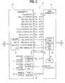
- FIG. 2 depicts a connection diagram showing electrical connections that may be established through the electrical connector set 30. Reference shall be made to FIG. 2 as appropriate to an understanding of the invention.
- the leads 22 of the patient monitor 12 may be connected to an appropriate set of heart monitoring locations on the body of the patient.
- AHA American Heart Association
- the leads may be connected to the left arm, right arm, left leg, right leg and chest.
- a cardiac signal processor 54 may detect a QRS complex of the patient and, in response, generate an R-marker pulse.
- the R-marker pulse may be transmitted through the connector 30 (e.g., through connector terminal #3) to a defibrillator control CPU 56.
- the R-marker may be used for defibrillator synchronization.
- the defibrillator 14 may be used in a pace maker mode.
- a beat rate and current may be selected through pushbuttons 32, 34 and shown on display 52.
- a timer 58 within the defibrillator 14 may be used to provide a pacemaker pulse interval.
- a pulse generator 29 may be used to generate a pacing pulse.
- the operator may activate a demand mode button 40.
- the timer 58 is reset each time an R-marker is received from the patient monitor 12.
- the controller 56 triggers the pulse generator 29 thereby pacing the heart in the absence of a detected heartbeat.
- the pulse generator 29 bypasses the shock capacitor 27. Bypassing the shock capacitor 27 is possible because of the lower energy needs of pacemaking and demand pacing.
- the R-marker may also be used for synchronous cardioversion. As above, an energy level may be selected through the pushbutton 46 and display 52. Upon activation of the shock button 42, the controller 56 may delay application of the cardioversion shock through the leads 20 until detection of the next R-marker from the monitor 12.
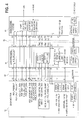
- FIG. 3 depicts a power distribution system 70 that may be used by the system 10 of FIG. 1.
- the monitor 12 conditionally shares power with the defibrillator 14.
- defibrillators typically require a battery technology (e.g., NiCd, lead-acid, etc.) which is capable of rapidly charging the shock capacitor 27.
- NiCd or lead-acid batteries have a very poor energy density. Further, in life threatening situations, it is considered better to have a monitor 12 with a dead battery than a defibrillator 14 with a dead battery.
- the defibrillator 14 uses power from the attached monitor 12 in preference to its own power to the greatest extent possible in order to conserve the energy within its own battery 28.
- Power from the monitor may be used to perform all defibrillator functions other than charging the shock capacitor 27. These functions include (but are not limited to) powering the processor, user interface, pacemaker, and battery charger 82.
- the pulse generator 29 under control of the CPU 56 functions to raise a voltage of a power supply main 88 to an appropriate level for pacing, cardioversion, etc.
- the defibrillator battery 28 will operate the entire defibrillator 14.
- the CPU 56 may activate switch 90 to supply power to the supply bus 88 and to the pulse generator 29.
- the CPU 56 may activate the voltage-to-voltage converter 86. Activation of the converter 86 charges the shock capacitor 27. Once the shock capacitor 27 is charged, the PCPU 80 may deliver the charge upon activation of the shock button 42 by activation of the switch 25.
- the monitor 12 may have one or more built-in or exchangeable battery packs 24, 26.
- the monitor 12 When the monitor 12 is operating on AC mains power from a plug 60 (FIG. 2), it supplies direct current (dc) power to the defibrillator 14 (FIGs. 2 and 3).
- the monitor 12 makes power available to the attached defibrillator 14 as follows. Under one illustrated embodiment, if the monitor 12 has an equal or greater number of exchangeable battery packs 24, 26 than the defibrillator 14, then the monitor 12 supplies power to the defibrillator 14. Conversely, if the monitor 12 has fewer exchangeable battery packs 28 than the defibrillator 14, then the monitor 12 may not supply power to the defibrillator 14.
- a power control processing unit (PCPU) 72 may monitor battery reserve capacity under any one of a number of formats.
- battery reserve may be determined by the number of connected batteries or by the charge level of the connected batteries.
- the PCPU 72 may monitor for the presence of battery packs 24, 26 through the use of sensors (e.g., limit switches, proximity detectors, etc.) 74, 76.
- a charge detector 72 may monitor a charge level of the batteries 24, 26 based upon voltage. Based upon the reserve capacity of the monitor (e.g., greater than 50%) and the number of batteries 24, 26 detected by sensors 74, 76, the PCPU 72 may operate a switch 78 to conditionally supply power to the defibrillator 14.
- the defibrillator 14 may consume power under control of a CPU 56. If situations where charging of the shock capacitor 27 is required, the CPU 56, under control of the switch 44, may cause the converter 86 to become active. Activation of the converter 86 causes the battery 28 to charge the shock capacitor 27.
- FIG. 4 depicts a docking station 90 that may be used with the patient monitoring unit 12 or defibrillator 14.
- the docking station 90 may be used for such things as programming and troubleshooting the patient monitoring unit 12 or the defibrillator 14.
- first and second connectors 30, 92 may be included on the docking station 90.
- the first connector 32 may be used to releasably couple the patient monitoring unit 12 to the defibrillator 14.
- the second connector 92 may be used to releasably couple the defibrillator 14 to the docking station 90.
- the docking station 90 may be provided with complementary connectors 30, 92.
- the docking station may also be provided with a male connector 30.
- the docking station 92 may be coupled to either the patient monitor unit 12 or the defibrillator 14.
- connectors 30, 92 may be provided with identification features to identify a connected device. For example, when the patient monitoring unit 12 is coupled to the defibrillator 14, a grounded pin #10 alerts the patient monitoring unit 12 to the presence of a connected device. The patient monitoring unit 12 may then transfer an identity request over a transmit port #12 and monitor a receive port #11 for an identifier. Alternatively, the patient monitoring unit 12 may transmit an identify request over ENET pins #5,7 and monitor ENET pins #6, 8 for a response.
Abstract
Description
- The field of the invention relates to cardiac defibrillation and more particularly to portable defibrillators.
- Cardiac arrest can occur in humans for any of a number of reasons. Triggering events may include heart attack, accidental contact with high voltage sources or disease. While the term "cardiac arrest" suggests a total cessation of heart function, a more accurate characterization may be a lack of coordinated contractions among the various segments of the heart. The lack of coordinated contractions may be further characterized by the term "fibrillation". Often cardiac arrest may be reversed through application of an electric shock from a defibrillator.
- Defibrillators have been constructed to operate under a number of different modes. Under a first mode, a defibrillator may deliver a one-time shock (usually in the case of full cardiac arrest) under control of an operator. Under other modes, the defibrillator may receive an R-marker from a heart monitor for other therapeutic processes (e.g., demand pacing, cardioversion, etc.).
- In the case of the sudden onset of cardiac failure, it is often necessary to use defibrillators in a mobile environment (e.g., during ambulance calls). Where used in the mobile environment, a defibrillator must rely upon battery power. However, batteries often deteriorate or become discharged during use. Because of the importance of defibrillators, a need exists for a more reliable method of supplying power to defibrillators in mobile environments.
- According to the invention, a method and apparatus are provided for distributing power within a cardiac treatment and monitoring system which includes a defibrillator releasably coupled to a patient monitoring unit. The method includes the steps of determining a battery reserve capacity within the patient monitoring unit and distributing power from the patient monitoring system to a defibrillator when the determined battery reserve capacity exceeds a threshold value.
- An embodiment of the invention will now be described, by way of example with reference to the accompanying drawings, in which:
- FIG. 1 is a front view of a cardiac treatment and monitoring system in accordance with an illustrated embodiment of the invention;
- FIG. 2 is a schematic of a connection diagram that may be used to couple a patient monitoring unit of the cardiac treatment and monitoring system to a defibrillator of the cardiac treatment and monitoring system of FIG. 1;
- FIG. 3 depicts a power distribution system used by the system of FIG. 1; and
- FIG. 4 depicts the cardiac treatment unit and defibrillator of FIG. 1 in connection with a docking station.
-
- FIG. 1 depicts a cardiac treatment and
monitoring system 10, shown generally under an illustrated embodiment of the invention. Included within thesystem 10 may be adefibrillation unit 14 andpatient monitor 12. - Under illustrated embodiments of the invention, the
patient monitor 12 may be releasably attached to thedefibrillation unit 14. When detached, eachdevice defibrillator 14 may be equipped with its own internal power source (e.g., a battery) 28 and internal control system to allow stand-alone use. Acontrol panel 16 may be provided for selection and control of defibrillation processes. A set ofleads 20 may be provided to couple an output of the defibrillator to a body of a patient (not shown). - For example, the operator (also not shown) may activate a power-on
button 48. The operator may then activate a power up/downbutton 46 to select a power level (in Joules) for defibrillating the patient. A selected power level may be shown on adisplay 52. - The
leads 20 may be applied to the patient. One lead may be applied to the right front chest and the second lead to the left back of the patient. - Following selection of a power level, the operator may activate a
charge button 44. Upon activation of thecharge button 44, power from thebattery 28 may flow through a voltage tovoltage converter 86 and into ashock capacitor 27. By activating the shock button 42, the operator may trigger aswitch 25, which applies a defibrillating shock through theleads 20 to the patient. - The
patient monitor 12 may also be provided with its own internal power source (e.g., a battery) 24, 26 and internal control system to allow stand-alone use. Acontrol panel 18 may be provided for selection and control of patient monitoring processes (e.g., electrocardiogram, blood pressure, CO2, invasive pressure monitoring, blood temperature, cardiac output, blood oxygen saturation, etc.). A set ofleads 22 may be provided which may be coupled to the patient for detection of parameters related to a particular patient monitoring process. - A
mechanical interface 31 is provided to secure and mount thepatient monitor 12 to thedefibrillator 14. An electrical interface (e.g., electrical connector set) 30 may also be provided to couple power and control signals between themonitor 12 anddefibrillator 14. - FIG. 2 depicts a connection diagram showing electrical connections that may be established through the electrical connector set 30. Reference shall be made to FIG. 2 as appropriate to an understanding of the invention.
- Under an illustrated embodiment of the invention, the leads 22 of the
patient monitor 12 may be connected to an appropriate set of heart monitoring locations on the body of the patient. Using American Heart Association (AHA) lead naming convention, the leads may be connected to the left arm, right arm, left leg, right leg and chest. - A
cardiac signal processor 54 may detect a QRS complex of the patient and, in response, generate an R-marker pulse. The R-marker pulse may be transmitted through the connector 30 (e.g., through connector terminal #3) to adefibrillator control CPU 56. Within thedefibrillator 14, the R-marker may be used for defibrillator synchronization. - For example, where a
pacer pushbutton 36 is activated, thedefibrillator 14 may be used in a pace maker mode. A beat rate and current may be selected throughpushbuttons display 52. Atimer 58 within thedefibrillator 14 may be used to provide a pacemaker pulse interval. Apulse generator 29 may be used to generate a pacing pulse. - Alternatively, the operator may activate a
demand mode button 40. In the demand mode, thetimer 58 is reset each time an R-marker is received from thepatient monitor 12. However, if an R-marker is not received within a predetermined time period, thecontroller 56 triggers thepulse generator 29 thereby pacing the heart in the absence of a detected heartbeat. - It should be noted, in this regard, that for pacemaking and demand pacing, the
pulse generator 29 bypasses theshock capacitor 27. Bypassing theshock capacitor 27 is possible because of the lower energy needs of pacemaking and demand pacing. - The R-marker may also be used for synchronous cardioversion. As above, an energy level may be selected through the
pushbutton 46 and display 52. Upon activation of the shock button 42, thecontroller 56 may delay application of the cardioversion shock through theleads 20 until detection of the next R-marker from themonitor 12. - FIG. 3 depicts a power distribution system 70 that may be used by the
system 10 of FIG. 1. Under illustrated embodiments of the invention, themonitor 12 conditionally shares power with thedefibrillator 14. As is known, defibrillators typically require a battery technology (e.g., NiCd, lead-acid, etc.) which is capable of rapidly charging theshock capacitor 27. However, NiCd or lead-acid batteries have a very poor energy density. Further, in life threatening situations, it is considered better to have amonitor 12 with a dead battery than adefibrillator 14 with a dead battery. - In general, the
defibrillator 14 uses power from the attachedmonitor 12 in preference to its own power to the greatest extent possible in order to conserve the energy within itsown battery 28. Power from the monitor may be used to perform all defibrillator functions other than charging theshock capacitor 27. These functions include (but are not limited to) powering the processor, user interface, pacemaker, and battery charger 82. Thepulse generator 29 under control of theCPU 56 functions to raise a voltage of a power supply main 88 to an appropriate level for pacing, cardioversion, etc. - If the
monitor 12 is not present or fails to deliver the necessary power, thedefibrillator battery 28 will operate theentire defibrillator 14. In this case, theCPU 56 may activateswitch 90 to supply power to thesupply bus 88 and to thepulse generator 29. Alternatively, theCPU 56 may activate the voltage-to-voltage converter 86. Activation of theconverter 86 charges theshock capacitor 27. Once theshock capacitor 27 is charged, thePCPU 80 may deliver the charge upon activation of the shock button 42 by activation of theswitch 25. - The
monitor 12 may have one or more built-in or exchangeable battery packs 24, 26. When themonitor 12 is operating on AC mains power from a plug 60 (FIG. 2), it supplies direct current (dc) power to the defibrillator 14 (FIGs. 2 and 3). When operating in the absence of AC mains power (i.e., on battery power), themonitor 12 makes power available to the attacheddefibrillator 14 as follows. Under one illustrated embodiment, if themonitor 12 has an equal or greater number of exchangeable battery packs 24, 26 than thedefibrillator 14, then themonitor 12 supplies power to thedefibrillator 14. Conversely, if themonitor 12 has fewer exchangeable battery packs 28 than thedefibrillator 14, then themonitor 12 may not supply power to thedefibrillator 14. - To monitor battery capacity in the
monitor 12, a power control processing unit (PCPU) 72 (functioning as a battery reserve capacity analyzer) may monitor battery reserve capacity under any one of a number of formats. For example, battery reserve may be determined by the number of connected batteries or by the charge level of the connected batteries. - For example, the
PCPU 72 may monitor for the presence of battery packs 24, 26 through the use of sensors (e.g., limit switches, proximity detectors, etc.) 74, 76. Acharge detector 72 may monitor a charge level of thebatteries batteries sensors PCPU 72 may operate aswitch 78 to conditionally supply power to thedefibrillator 14. - Similarly, the
defibrillator 14 may consume power under control of aCPU 56. If situations where charging of theshock capacitor 27 is required, theCPU 56, under control of theswitch 44, may cause theconverter 86 to become active. Activation of theconverter 86 causes thebattery 28 to charge theshock capacitor 27. - FIG. 4 depicts a
docking station 90 that may be used with thepatient monitoring unit 12 ordefibrillator 14. Thedocking station 90 may be used for such things as programming and troubleshooting thepatient monitoring unit 12 or thedefibrillator 14. - Included on the
docking station 90 may be first andsecond connectors first connector 32 may be used to releasably couple thepatient monitoring unit 12 to thedefibrillator 14. Thesecond connector 92 may be used to releasably couple thedefibrillator 14 to thedocking station 90. - Alternatively, the
docking station 90 may be provided withcomplementary connectors female connector 30 and the defibrillator has amale connector 30, then the docking station may also be provided with amale connector 30. Where provided withcomplementary connectors docking station 92 may be coupled to either thepatient monitor unit 12 or thedefibrillator 14. - To facilitate use of the
docking station 90 with either the patient monitor 12 or defibrillator,connectors patient monitoring unit 12 is coupled to thedefibrillator 14, a groundedpin # 10 alerts thepatient monitoring unit 12 to the presence of a connected device. Thepatient monitoring unit 12 may then transfer an identity request over a transmitport # 12 and monitor a receiveport # 11 for an identifier. Alternatively, thepatient monitoring unit 12 may transmit an identify request over ENET pins #5,7 and monitorENET pins #
Claims (10)
- A cardiac treatment and monitoring system comprising:a patient analyzer unit [12] adapted to detect and analyze processes occurring within a body of a patient;a defibrillator unit [14] releasably coupled to the patient analyzer unit [12] and adapted to receive information about the detected and analyzed processes from the patient analyzer [12]; anda power distribution system [70] disposed within the patient analyzer unit [12] and adapted to conditionally share power from a power source of the patient analyzer with the defibrillator [14].
- The cardiac treatment and monitoring system as in claim 1 wherein the power source comprises a plurality of batteries [24, 26].
- The cardiac treatment and monitoring system as in claim 2 wherein the power distribution system further comprises a battery capacity analyzer [72] adapted to determine a battery capacity of the patient analyzer unit [12].
- The cardiac treatment and monitoring system as in claim 2 further comprising a power switch [78] disposed within the patient analyzer unit and adapted to couple power from the plurality of batteries [24, 26] to the defibrillator [14] when the battery capacity analyzer determines that a reserve capacity of the plurality of batteries exceeds a threshold value.
- A method of distributing power within a cardiac treatment and monitoring system which includes a defibrillator [14] releasably coupled to a patient monitoring unit [12], such method comprising the steps of:determining a battery reserve capacity within the patient monitoring unit [12]; anddistributing power from the patient monitoring system [12] to a defibrillator [14] when the determined battery reserve capacity exceeds a threshold value.
- An apparatus for distributing power within a cardiac treatment and monitoring system which includes a defibrillator releasably coupled to a patient monitoring unit, such apparatus comprising:means for distributing power to a defibrillator [14] when the determined battery reserve capacity exceeds a threshold value.means for determining a battery reserve capacity within the patient monitoring unit [12]; and
- The apparatus for distributing power as in claim 6 wherein the means for determining a battery reserve capacity further comprises means for determining a number of batteries [24, 26] coupled to the patient monitoring system [12].
- The apparatus for distributing power as in claim 7 wherein the means for determining a battery reserve capacity further comprises means for determining if the number of batteries [24, 26] coupled to the patient monitoring system exceeds a number of batteries coupled to the defibrillator [14].
- An apparatus for distributing power within a cardiac treatment and monitoring system which includes a defibrillator releasably coupled to a patient monitoring unit, such apparatus comprising:a battery reserve capacity analyzer adapted to determine a battery reserve capacity [72] within the patient monitoring unit [12]; anda power distribution system [70] adapted to distribute power to a defibrillator [14] when the determined battery reserve capacity exceeds a threshold value.
- A cardiac treatment and monitoring system comprising:a cardiac analyzer unit adapted to detect and analyze a QRS complex of a patient;a defibrillator unit [14] adapted to receive QRS information of the analyzed QRS complex from the cardiac analyzer; anda power distribution system [70] disposed within the cardiac analyzer unit [12] and adapted to conditionally share power from a power source of the cardiac analyzer with the defibrillator [14].
Applications Claiming Priority (2)
| Application Number | Priority Date | Filing Date | Title |
|---|---|---|---|
| US835459 | 1997-04-08 | ||
| US09/835,459 US6591135B2 (en) | 2001-04-16 | 2001-04-16 | Portable patient monitor with defibrillator/pacemaker interface and battery power management |
Publications (3)
| Publication Number | Publication Date |
|---|---|
| EP1250944A2 true EP1250944A2 (en) | 2002-10-23 |
| EP1250944A3 EP1250944A3 (en) | 2005-01-05 |
| EP1250944B1 EP1250944B1 (en) | 2007-11-21 |
Family
ID=25269553
Family Applications (1)
| Application Number | Title | Priority Date | Filing Date |
|---|---|---|---|
| EP02252674A Expired - Lifetime EP1250944B1 (en) | 2001-04-16 | 2002-04-16 | Portable patient monitor with defibrillator/pacemaker interface and battery power management |
Country Status (4)
| Country | Link |
|---|---|
| US (1) | US6591135B2 (en) |
| EP (1) | EP1250944B1 (en) |
| JP (1) | JP2002360711A (en) |
| DE (1) | DE60223618T2 (en) |
Cited By (14)
| Publication number | Priority date | Publication date | Assignee | Title |
|---|---|---|---|---|
| WO2005058413A2 (en) * | 2003-12-17 | 2005-06-30 | Medtronic Physio-Control Corp. | Defibrillator patient monitoring pod |
| EP1610437A1 (en) * | 2004-05-28 | 2005-12-28 | Advanced Neuromodulation Systems, Inc. | Systems and methods used to reserve a constant battery capacity |
| EP1778346A2 (en) * | 2004-07-30 | 2007-05-02 | Access Cardiosystems, Inc | Method and apparatus for determining battery capacity in a defibrillator |
| US7957798B2 (en) | 2003-12-17 | 2011-06-07 | Physio-Control, Inc. | Defibrillator/monitor system having a pod with leads capable of wirelessly communicating |
| US8600491B2 (en) | 2003-12-17 | 2013-12-03 | Physio-Control, Inc. | Defibrillator patient monitoring pod |
| WO2014059246A3 (en) * | 2012-10-11 | 2014-06-19 | Heartlife Technology, Llc | Automated external defibrillator attachment for electronic device |
| WO2016139234A1 (en) * | 2015-03-03 | 2016-09-09 | Koninklijke Philips N.V. | Modular medical system for patient monitoring and electrical therapy delivery |
| US9872998B2 (en) | 2012-05-08 | 2018-01-23 | Physio-Control, Inc. | Defibrillator communication system |
| EP3215003A4 (en) * | 2014-11-07 | 2018-08-22 | Welch Allyn, Inc. | Medical device |
| US10303852B2 (en) | 2012-07-02 | 2019-05-28 | Physio-Control, Inc. | Decision support tool for use with a medical monitor-defibrillator |
| US10299668B2 (en) | 2005-10-21 | 2019-05-28 | Physio-Control, Inc. | Laryngoscope with handle-grip activated recording |
| US10413742B2 (en) | 2008-03-05 | 2019-09-17 | Physio-Control, Inc. | Defibrillator patient monitoring pod |
| US10426965B2 (en) | 2004-07-30 | 2019-10-01 | Scion Medical Limited | Method and apparatus for determining battery capacity in a defibrillator |
| US11166628B2 (en) | 2016-02-02 | 2021-11-09 | Physio-Control, Inc. | Laryngoscope with handle-grip activated recording |
Families Citing this family (28)
| Publication number | Priority date | Publication date | Assignee | Title |
|---|---|---|---|---|
| WO2000016839A1 (en) * | 1998-09-23 | 2000-03-30 | The Johns Hopkins University | Emergency life support system |
| US20020165585A1 (en) * | 2001-05-01 | 2002-11-07 | Dupelle Michael R. | Pulse sensors |
| US7191008B2 (en) * | 2001-05-30 | 2007-03-13 | Medtronic, Inc. | Implantable medical device with a dual power source |
| US7848805B2 (en) * | 2001-07-20 | 2010-12-07 | Koninklijke Philips Electronics N.V. | Modular medical device, base unit and module thereof, and automated external defibrillator (AED), methods for assembling and using the AED |
| US20030028219A1 (en) * | 2001-07-20 | 2003-02-06 | Powers Daniel J. | Modular medical device, base unit and module thereof, and automated external defibrillator (AED), methods for assembling and using the AED |
| US7016727B2 (en) * | 2001-11-05 | 2006-03-21 | Koninklijke Philips Electronics N.V. | Cartridge having a power source and electrode pad for defibrillator having a rechargeable battery |
| US20030117442A1 (en) * | 2001-12-26 | 2003-06-26 | Yuemean Chen | Dynamic indication for capacitor charging status |
| US9088166B2 (en) * | 2002-04-30 | 2015-07-21 | Physio-Control, Inc. | External charging pack and medical device with internal battery rechargable from external charging pack |
| AU2003273605A1 (en) | 2002-06-11 | 2003-12-22 | Matos, Jeffrey A | System for cardiac resuscitation |
| US20060142808A1 (en) * | 2003-04-22 | 2006-06-29 | Christopher Pearce | Defibrillator/monitor system having a pod with leads capable of wirelessly communicating |
| US20040215244A1 (en) * | 2003-04-23 | 2004-10-28 | Marcovecchio Alan F. | Processing pulse signal in conjunction with ECG signal to detect pulse in external defibrillation |
| US7769465B2 (en) | 2003-06-11 | 2010-08-03 | Matos Jeffrey A | System for cardiac resuscitation |
| EP1673143B1 (en) * | 2003-10-02 | 2012-08-22 | Medtronic, Inc. | User interface for external charger for implantable medical device |
| US9259584B2 (en) | 2003-10-02 | 2016-02-16 | Medtronic, Inc. | External unit for implantable medical device coupled by cord |
| US7706878B2 (en) | 2004-05-07 | 2010-04-27 | Zoll Medical Corporation | Automated caregiving device with prompting based on caregiver progress |
| JP4711665B2 (en) * | 2004-11-26 | 2011-06-29 | 九州日立マクセル株式会社 | Combination therapy device |
| EP1850734A4 (en) | 2005-01-13 | 2009-08-26 | Welch Allyn Inc | Vital signs monitor |
| US20090005651A1 (en) * | 2007-06-27 | 2009-01-01 | Welch Allyn, Inc. | Portable systems, devices and methods for displaying varied information depending on usage circumstances |
| EP3007766B1 (en) * | 2013-06-11 | 2018-11-21 | Koninklijke Philips N.V. | Synchronized cardioversion mixed mode operation and timing verification |
| WO2015017718A1 (en) | 2013-08-01 | 2015-02-05 | Zoll Medical Corporation | Systems and methods for utilizing identification devices in a wearable medical therapy device |
| EP4218559A1 (en) | 2014-02-25 | 2023-08-02 | ICU Medical, Inc. | Patient monitoring system with gatekeeper signal |
| TWI599381B (en) * | 2014-08-13 | 2017-09-21 | 華邦電子股份有限公司 | Defibrillator device |
| US9636513B2 (en) * | 2015-01-21 | 2017-05-02 | Winbond Electronics Corp. | Defibrillator device |
| US9886680B2 (en) * | 2015-03-24 | 2018-02-06 | Zoll Medical Corporation | Low-power signaling for medical devices and medical device personnel |
| CA3105936C (en) | 2015-10-19 | 2023-08-01 | Icu Medical, Inc. | Hemodynamic monitoring system with detachable display unit |
| US11179286B2 (en) | 2016-10-21 | 2021-11-23 | Zoll Medical Corporation | Adaptive body positioning |
| US10737105B2 (en) | 2017-10-02 | 2020-08-11 | Avive Solutions, Inc. | Modular defibrillator architecture |
| CA3077596A1 (en) * | 2017-10-02 | 2019-04-11 | Avive Solutions, Inc. | Modular defibrillator architecture |
Citations (4)
| Publication number | Priority date | Publication date | Assignee | Title |
|---|---|---|---|---|
| US3865101A (en) * | 1974-05-01 | 1975-02-11 | Datascope Corp | Portable and separable heart monitor and heart defibrillator apparatus |
| US4080558A (en) * | 1974-12-30 | 1978-03-21 | Gould Inc. | Defibrillator battery charger |
| US4096856A (en) * | 1976-09-03 | 1978-06-27 | Physio-Control Corporation | Portable electronic physiological instrument having separable first and second components, and improved mechanical connector therefor |
| US4653474A (en) * | 1984-07-06 | 1987-03-31 | Office de Distribution D'Appareils Medicaux | Portable electromedical device |
Family Cites Families (2)
| Publication number | Priority date | Publication date | Assignee | Title |
|---|---|---|---|---|
| US5975081A (en) * | 1996-06-21 | 1999-11-02 | Northrop Grumman Corporation | Self-contained transportable life support system |
| US6223077B1 (en) * | 1998-01-26 | 2001-04-24 | Physio-Control Manufacturing Corporation | Automatic power switching in a defibrillator |
-
2001
- 2001-04-16 US US09/835,459 patent/US6591135B2/en not_active Expired - Fee Related
-
2002
- 2002-04-15 JP JP2002111540A patent/JP2002360711A/en active Pending
- 2002-04-16 EP EP02252674A patent/EP1250944B1/en not_active Expired - Lifetime
- 2002-04-16 DE DE60223618T patent/DE60223618T2/en not_active Expired - Lifetime
Patent Citations (4)
| Publication number | Priority date | Publication date | Assignee | Title |
|---|---|---|---|---|
| US3865101A (en) * | 1974-05-01 | 1975-02-11 | Datascope Corp | Portable and separable heart monitor and heart defibrillator apparatus |
| US4080558A (en) * | 1974-12-30 | 1978-03-21 | Gould Inc. | Defibrillator battery charger |
| US4096856A (en) * | 1976-09-03 | 1978-06-27 | Physio-Control Corporation | Portable electronic physiological instrument having separable first and second components, and improved mechanical connector therefor |
| US4653474A (en) * | 1984-07-06 | 1987-03-31 | Office de Distribution D'Appareils Medicaux | Portable electromedical device |
Cited By (27)
| Publication number | Priority date | Publication date | Assignee | Title |
|---|---|---|---|---|
| US8788038B2 (en) | 2003-12-17 | 2014-07-22 | Physio-Control, Inc. | External defibrillator with power and battery sharing capabilities with a pod |
| WO2005058416A1 (en) * | 2003-12-17 | 2005-06-30 | Medtronic Physio-Control Corp. | An external defibrillator with power and battery sharing capabilities with a pod |
| WO2005058413A3 (en) * | 2003-12-17 | 2005-10-20 | Medtronic Physio Control Corp | Defibrillator patient monitoring pod |
| US10124184B2 (en) | 2003-12-17 | 2018-11-13 | Physio-Control, Inc. | Defibrillator/monitor system having a pod with leads capable of wirelessly communicating |
| WO2005058413A2 (en) * | 2003-12-17 | 2005-06-30 | Medtronic Physio-Control Corp. | Defibrillator patient monitoring pod |
| US7957798B2 (en) | 2003-12-17 | 2011-06-07 | Physio-Control, Inc. | Defibrillator/monitor system having a pod with leads capable of wirelessly communicating |
| US8600491B2 (en) | 2003-12-17 | 2013-12-03 | Physio-Control, Inc. | Defibrillator patient monitoring pod |
| US9439572B2 (en) | 2003-12-17 | 2016-09-13 | Physio-Control, Inc. | Defibrillator/monitor system having a pod with leads capable of wirelessly communicating |
| EP1610437A1 (en) * | 2004-05-28 | 2005-12-28 | Advanced Neuromodulation Systems, Inc. | Systems and methods used to reserve a constant battery capacity |
| US7450991B2 (en) | 2004-05-28 | 2008-11-11 | Advanced Neuromodulation Systems, Inc. | Systems and methods used to reserve a constant battery capacity |
| EP1778346A4 (en) * | 2004-07-30 | 2010-09-29 | Access Cardiosystems Inc | Method and apparatus for determining battery capacity in a defibrillator |
| EP1778346A2 (en) * | 2004-07-30 | 2007-05-02 | Access Cardiosystems, Inc | Method and apparatus for determining battery capacity in a defibrillator |
| US10426965B2 (en) | 2004-07-30 | 2019-10-01 | Scion Medical Limited | Method and apparatus for determining battery capacity in a defibrillator |
| US10299668B2 (en) | 2005-10-21 | 2019-05-28 | Physio-Control, Inc. | Laryngoscope with handle-grip activated recording |
| US10413742B2 (en) | 2008-03-05 | 2019-09-17 | Physio-Control, Inc. | Defibrillator patient monitoring pod |
| US10105546B2 (en) | 2012-05-08 | 2018-10-23 | Physio-Control, Inc. | Utility module |
| US10118048B2 (en) | 2012-05-08 | 2018-11-06 | Physio-Control, Inc. | Utility module system |
| US10124181B2 (en) | 2012-05-08 | 2018-11-13 | Physio-Control., Inc. | Defibrillator network system |
| US10159846B2 (en) | 2012-05-08 | 2018-12-25 | Physio-Control, Inc. | Utility module interface |
| US9872998B2 (en) | 2012-05-08 | 2018-01-23 | Physio-Control, Inc. | Defibrillator communication system |
| US10926099B2 (en) | 2012-05-08 | 2021-02-23 | Physio-Control, Inc. | Utility module interface |
| US10303852B2 (en) | 2012-07-02 | 2019-05-28 | Physio-Control, Inc. | Decision support tool for use with a medical monitor-defibrillator |
| WO2014059246A3 (en) * | 2012-10-11 | 2014-06-19 | Heartlife Technology, Llc | Automated external defibrillator attachment for electronic device |
| EP3215003A4 (en) * | 2014-11-07 | 2018-08-22 | Welch Allyn, Inc. | Medical device |
| US10405758B2 (en) | 2014-11-07 | 2019-09-10 | Welch Allyn, Inc. | Carrier assembly for blood pressure module |
| WO2016139234A1 (en) * | 2015-03-03 | 2016-09-09 | Koninklijke Philips N.V. | Modular medical system for patient monitoring and electrical therapy delivery |
| US11166628B2 (en) | 2016-02-02 | 2021-11-09 | Physio-Control, Inc. | Laryngoscope with handle-grip activated recording |
Also Published As
| Publication number | Publication date |
|---|---|
| DE60223618T2 (en) | 2008-10-23 |
| JP2002360711A (en) | 2002-12-17 |
| DE60223618D1 (en) | 2008-01-03 |
| US20030088275A1 (en) | 2003-05-08 |
| EP1250944A3 (en) | 2005-01-05 |
| EP1250944B1 (en) | 2007-11-21 |
| US6591135B2 (en) | 2003-07-08 |
Similar Documents
| Publication | Publication Date | Title |
|---|---|---|
| EP1250944B1 (en) | Portable patient monitor with defibrillator/pacemaker interface and battery power management | |
| EP1370326B1 (en) | Defibrillator with detection of cardipulmonary resuscitation | |
| US20180214705A1 (en) | External defibrillator with power and battery sharing capabilities with a pod | |
| US20020103508A1 (en) | Remotely operated defibrillator | |
| US9636513B2 (en) | Defibrillator device | |
| EP1372784B1 (en) | Four contact identification defibrillator electrode system | |
| US20090295326A1 (en) | Defibrillator Battery Authentication System | |
| US6405082B1 (en) | Method and apparatus for distinguishing between therapy modes in a defibrillator | |
| EP1289603A1 (en) | A public access defibrillator | |
| US9138592B2 (en) | Defibrillation system and method and defibrillator electrode device | |
| CN105324153B (en) | Synchronous electric cardioversion mixed mode operations and timing verification | |
| US8788038B2 (en) | External defibrillator with power and battery sharing capabilities with a pod | |
| US20100114236A1 (en) | Hybrid battery system with bioelectric cell for implantable cardiac therapy device | |
| US8862227B2 (en) | Defibrillators detecting orientation of electrode connection to adjust energy dosage | |
| US6360120B1 (en) | Method and apparatus for transferring patient data generated by an external defibrillator | |
| US20100114235A1 (en) | Hybrid battery system for implantable cardiac therapy device | |
| US6438415B1 (en) | Method and apparatus for controlling the operation and functionality of an electrotherapy device | |
| US20220193432A1 (en) | Battery Management for Medical Device | |
| CN209885035U (en) | Emergency equipment | |
| US20200316393A1 (en) | Systems and methods for double sequential defibrillation | |
| JP2023519633A (en) | WCD system and its management method | |
| CN111375131A (en) | Emergency equipment | |
| CN115149610A (en) | Defibrillation equipment power supply control system and method |
Legal Events
| Date | Code | Title | Description |
|---|---|---|---|
| PUAI | Public reference made under article 153(3) epc to a published international application that has entered the european phase |
Free format text: ORIGINAL CODE: 0009012 |
|
| AK | Designated contracting states |
Kind code of ref document: A2 Designated state(s): AT BE CH CY DE DK ES FI FR GB GR IE IT LI LU MC NL PT SE TR |
|
| AX | Request for extension of the european patent |
Free format text: AL;LT;LV;MK;RO;SI |
|
| PUAL | Search report despatched |
Free format text: ORIGINAL CODE: 0009013 |
|
| AK | Designated contracting states |
Kind code of ref document: A3 Designated state(s): AT BE CH CY DE DK ES FI FR GB GR IE IT LI LU MC NL PT SE TR |
|
| AX | Request for extension of the european patent |
Extension state: AL LT LV MK RO SI |
|
| 17P | Request for examination filed |
Effective date: 20050705 |
|
| AKX | Designation fees paid |
Designated state(s): DE FR GB |
|
| GRAP | Despatch of communication of intention to grant a patent |
Free format text: ORIGINAL CODE: EPIDOSNIGR1 |
|
| RIN1 | Information on inventor provided before grant (corrected) |
Inventor name: SCHULZ, ANDREAS Inventor name: SCHLOSSER HORST Inventor name: LOEHNING, WILFRIED Inventor name: CLAPP, ALAN EDWARD Inventor name: BAYER, BRIAN JOSEPH Inventor name: SCHIEBLE, DAVID L. Inventor name: PALMER, MICHAEL J. Inventor name: GRAY, JAMES MICHAEL |
|
| GRAS | Grant fee paid |
Free format text: ORIGINAL CODE: EPIDOSNIGR3 |
|
| GRAA | (expected) grant |
Free format text: ORIGINAL CODE: 0009210 |
|
| AK | Designated contracting states |
Kind code of ref document: B1 Designated state(s): DE FR GB |
|
| REG | Reference to a national code |
Ref country code: GB Ref legal event code: FG4D |
|
| REF | Corresponds to: |
Ref document number: 60223618 Country of ref document: DE Date of ref document: 20080103 Kind code of ref document: P |
|
| ET | Fr: translation filed | ||
| PLBE | No opposition filed within time limit |
Free format text: ORIGINAL CODE: 0009261 |
|
| STAA | Information on the status of an ep patent application or granted ep patent |
Free format text: STATUS: NO OPPOSITION FILED WITHIN TIME LIMIT |
|
| 26N | No opposition filed |
Effective date: 20080822 |
|
| PGFP | Annual fee paid to national office [announced via postgrant information from national office to epo] |
Ref country code: FR Payment date: 20080417 Year of fee payment: 7 |
|
| PGFP | Annual fee paid to national office [announced via postgrant information from national office to epo] |
Ref country code: GB Payment date: 20080429 Year of fee payment: 7 |
|
| GBPC | Gb: european patent ceased through non-payment of renewal fee |
Effective date: 20090416 |
|
| REG | Reference to a national code |
Ref country code: FR Ref legal event code: ST Effective date: 20091231 |
|
| PG25 | Lapsed in a contracting state [announced via postgrant information from national office to epo] |
Ref country code: FR Free format text: LAPSE BECAUSE OF NON-PAYMENT OF DUE FEES Effective date: 20091222 Ref country code: GB Free format text: LAPSE BECAUSE OF NON-PAYMENT OF DUE FEES Effective date: 20090416 |
|
| PGFP | Annual fee paid to national office [announced via postgrant information from national office to epo] |
Ref country code: DE Payment date: 20140429 Year of fee payment: 13 |
|
| REG | Reference to a national code |
Ref country code: DE Ref legal event code: R119 Ref document number: 60223618 Country of ref document: DE |
|
| PG25 | Lapsed in a contracting state [announced via postgrant information from national office to epo] |
Ref country code: DE Free format text: LAPSE BECAUSE OF NON-PAYMENT OF DUE FEES Effective date: 20151103 |