EP1248404A2 - Apparatus and method for transmitting/receiving data in a CDMA mobile communication system - Google Patents
Apparatus and method for transmitting/receiving data in a CDMA mobile communication system Download PDFInfo
- Publication number
- EP1248404A2 EP1248404A2 EP20020007674 EP02007674A EP1248404A2 EP 1248404 A2 EP1248404 A2 EP 1248404A2 EP 20020007674 EP20020007674 EP 20020007674 EP 02007674 A EP02007674 A EP 02007674A EP 1248404 A2 EP1248404 A2 EP 1248404A2
- Authority
- EP
- European Patent Office
- Prior art keywords
- bits
- relatively lower
- priority
- higher priority
- bit
- Prior art date
- Legal status (The legal status is an assumption and is not a legal conclusion. Google has not performed a legal analysis and makes no representation as to the accuracy of the status listed.)
- Ceased
Links
Images


Classifications
-
- H—ELECTRICITY
- H04—ELECTRIC COMMUNICATION TECHNIQUE
- H04L—TRANSMISSION OF DIGITAL INFORMATION, e.g. TELEGRAPHIC COMMUNICATION
- H04L1/00—Arrangements for detecting or preventing errors in the information received
- H04L1/004—Arrangements for detecting or preventing errors in the information received by using forward error control
- H04L1/0056—Systems characterized by the type of code used
- H04L1/0064—Concatenated codes
- H04L1/0066—Parallel concatenated codes
-
- H—ELECTRICITY
- H04—ELECTRIC COMMUNICATION TECHNIQUE
- H04B—TRANSMISSION
- H04B7/00—Radio transmission systems, i.e. using radiation field
- H04B7/14—Relay systems
- H04B7/15—Active relay systems
- H04B7/204—Multiple access
- H04B7/216—Code division or spread-spectrum multiple access [CDMA, SSMA]
-
- H—ELECTRICITY
- H04—ELECTRIC COMMUNICATION TECHNIQUE
- H04L—TRANSMISSION OF DIGITAL INFORMATION, e.g. TELEGRAPHIC COMMUNICATION
- H04L1/00—Arrangements for detecting or preventing errors in the information received
- H04L1/004—Arrangements for detecting or preventing errors in the information received by using forward error control
- H04L1/0056—Systems characterized by the type of code used
- H04L1/0067—Rate matching
- H04L1/0068—Rate matching by puncturing
-
- H—ELECTRICITY
- H04—ELECTRIC COMMUNICATION TECHNIQUE
- H04L—TRANSMISSION OF DIGITAL INFORMATION, e.g. TELEGRAPHIC COMMUNICATION
- H04L1/00—Arrangements for detecting or preventing errors in the information received
- H04L1/004—Arrangements for detecting or preventing errors in the information received by using forward error control
- H04L1/0056—Systems characterized by the type of code used
- H04L1/007—Unequal error protection
-
- H—ELECTRICITY
- H04—ELECTRIC COMMUNICATION TECHNIQUE
- H04L—TRANSMISSION OF DIGITAL INFORMATION, e.g. TELEGRAPHIC COMMUNICATION
- H04L1/00—Arrangements for detecting or preventing errors in the information received
- H04L1/004—Arrangements for detecting or preventing errors in the information received by using forward error control
- H04L1/0056—Systems characterized by the type of code used
- H04L1/0071—Use of interleaving
-
- H—ELECTRICITY
- H04—ELECTRIC COMMUNICATION TECHNIQUE
- H04L—TRANSMISSION OF DIGITAL INFORMATION, e.g. TELEGRAPHIC COMMUNICATION
- H04L1/00—Arrangements for detecting or preventing errors in the information received
- H04L1/08—Arrangements for detecting or preventing errors in the information received by repeating transmission, e.g. Verdan system
-
- H—ELECTRICITY
- H04—ELECTRIC COMMUNICATION TECHNIQUE
- H04L—TRANSMISSION OF DIGITAL INFORMATION, e.g. TELEGRAPHIC COMMUNICATION
- H04L27/00—Modulated-carrier systems
- H04L27/32—Carrier systems characterised by combinations of two or more of the types covered by groups H04L27/02, H04L27/10, H04L27/18 or H04L27/26
- H04L27/34—Amplitude- and phase-modulated carrier systems, e.g. quadrature-amplitude modulated carrier systems
- H04L27/3488—Multiresolution systems
-
- H—ELECTRICITY
- H04—ELECTRIC COMMUNICATION TECHNIQUE
- H04L—TRANSMISSION OF DIGITAL INFORMATION, e.g. TELEGRAPHIC COMMUNICATION
- H04L1/00—Arrangements for detecting or preventing errors in the information received
- H04L2001/0098—Unequal error protection
Definitions
- the present invention relates generally to an apparatus and method for transmitting/receiving data in a CDMA (Code Division Multiple Access) mobile communication system, and in particular, to a data transmission/reception apparatus and method for improving reliability of transport data bits.
- CDMA Code Division Multiple Access
- An error control coding technique has been proposed as a typical method of minimizing the effects of the distortions or noises.
- Codes used for the error control coding technique are classified into a memoryless code and a memory code.
- the memoryless code includes a linear block code
- the memory code includes a convolutional code and a turbo code.
- a device for generating such codes is called a "channel encoder", and its outputs can be divided into systematic bits and parity bits based on the error control coding technique.
- the turbo code is a code typically used for the error control coding technique that separates its outputs into the systematic bits and the parity bits.
- there exists a systematic convolutional code of the convolutional code as a code used for the error control coding technique.
- the "systematic bits” mean an actual information signal
- the "parity bits” mean a supplemental signal added to correct a possible error which occurred during transportation in a decoding process.
- a signal is subjected to the error control coding, if a burst error occurs in the systematic bits or the parity bits, it is not easy to correct the burst error.
- Such a phenomenon frequently occurs while the signal passes through a fading channel, and an "interleaving" technique is typically used to prevent this phenomenon.
- the interleaving technique disperses a damaged part in several places rather than concentrating it on a single place, thereby complementing the error control coding technique.
- Such interleaved signal is subject to mapping in a symbol unit in a digital modulator.
- the number of bits included in one symbol increases with the order of the modulator.
- one symbol includes information of over 4 bits, and the bits can be classified according to reliability.
- the "reliability" can be represented by a probability that the bit values will be changed during transportation. For example, when one 16QAM-modualted symbol is subject to mapping on coordinates, information of leading two bits in the symbol has higher reliability since the leading two bits determine a quadrant of the coordinates, to which the symbol is to be mapped. This means that there is a lower probability that the information of the leading two bits will be changed during transportation.
- information of the remaining two bits in the symbol has lower reliability, since the remaining two bits determine one of the four regions obtained by dividing the determined quadrant. This means that there is a higher probability that the information of the remaining two bits will be changed during transportation. That is, of at least 3 bits included in one symbol, the bits determining a wider region have higher reliability and the bits determining a narrower region have lower reliability.
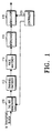
- a transmitter of a common HSDPA (High-Speed Downlink Packet Access) radio communication system is comprised of a channel encoder, an interleaver and a modulator, as illustrated in FIG. 1.
- HSDPA High-Speed Downlink Packet Access
- a tail bit generator 110 receives N transport blocks and adds associated tail bits to the respective transport blocks.
- a channel encoder 112 encodes the N tail bit-added transport blocks from the tail bit generator 110 and outputs coded symbols.
- the channel encoder 112 has at least one coding rate in order to encode the N transport blocks.
- the coding rate may be 1/2 or 3/4.
- the channel encoder 112 supports a plurality of coding rates through symbol puncturing or symbol repetition using a 1/6 or 1/5 mother encoder, an operation of selecting a coding rate from the available coding rates is required.
- the channel encoder 112 determines (selects) the coding rate under the control of a controller 120.
- a rate matcher 114 rate-matches the coded symbols from the channel encoder 112.
- the rate matching is performed by repeating or puncturing the coded symbols, when a transport channel is subject to multiplexing or when the number of the output symbols of the channel encoder 112 is not identical to the number of symbols transported over a radio channel.
- An interleaver 116 interleaves the rate-matched coded symbols from the rate matcher 114. The interleaving is performed to minimize a possible data loss during transportation.
- An M-ary modulator 118 modulates the interleaved coded symbols by QPSK (Quadrature Phase Shift Keying), 8PSK (8-ary Phase Shift Keying), 16QAM or 64QAM modulation.
- the controller 120 controls an operation of the channel encoder (or turbo encoder) 112 and a modulation mode of the modulator 118 according to a current state of the radio channel.
- the HSDPA radio communication system uses AMCS (Adaptive Modulation and Coding Scheme) for the controller 120 in order to select the modulation modes (QPSK, 8PSK, 16QAM and 64QAM) according to the radio environment.
- AMCS Adaptive Modulation and Coding Scheme
- the CDMA mobile Communication system spreads transport data using a Walsh code W and an orthogonal code PN, so that a corresponding mobile terminal (or UE (User Equipment)) can identify a channel and a base station (or Node B) transmitting the data.
- the structure of the transmitter has been described on the assumption that coded symbols are not divided into the systematic bits and the parity bits.
- the coded symbols output from the channel encoder 112 of the transmitter can be divided into the systematic bits and the parity bits.
- the systematic bits and the parity bits output from the channel encoder 112 have different priorities. Namely, in the case where errors occur in the transport data at a given rate, it is possible to perform relatively correct decoding when the errors occur in the parity bits rather than in the systematic bits. The reason is, as stated above, because the systematic bits are actual data bits while the parity bits are supplemental bits added to correct errors occurred during transportation in a decoding process.
- the interleaver 116 of the conventional transmitter in the communication system performs interleaving regardless of the priorities of the systematic bits and the parity bits. That is, the conventional transmitter performs symbol mapping irrespective of the systematic bits and the parity bits.
- the conventional radio communication system has a high error occurrence probability regardless of the priorities of the systematic bits and the parity bits, when transporting data over the wireless network. Accordingly, there is a need for a technique capable of reducing a probability that errors will occur in the systematic bits having higher priority than the parity bits, thereby improving system performance.
- an object of the present invention to provide a data transmission/reception apparatus and method for improving performance of a radio communication system.
- the present invention provides a data transmission apparatus and method for dividing transport data bits into bits having higher priority and bits having lower priority, mapping the bits having higher priority to symbol bit positions having higher reliability, and mapping the bits having lower priority to symbol bit positions having lower reliability.
- the present invention provides a data reception apparatus and method for demodulating received modulated symbols, dividing the demodulated coded bits into two coded bit groups according to priority, deinterleaving the coded bit groups using different deinterleavers, and decoding the deinterleaved coded bits.
- the channel encoder supports a coding rate of 1/2 and 3/4
- the modulator supports QPSK, 8PSK, 16QAM and 64QAM. Shown in Table 1 are available encoding operations according to an embodiment of the present invention, when the assumption stated above is applied. Coding Rate Modulation Mode 1/2 QPSK 8PSK 16QAM 64QAM 3/4 QPSK 8PSK 16QAM 64QAM
- the channel encoder outputs 2 bits by receiving one input bit.
- One of the 2 output bits is an actual data bit, a systematic bit, while the remaining one bit is a parity bit for detecting and compensating for an error.
- the channel encoder outputs 4 bits by receiving 3 input bits. The 4 output bits are divided into 3 systematic bits and one parity bit.
- a symbol pattern based on the 16QAM can be expressed as [H,H,L,L]
- a symbol pattern based on the 64QAM can be expressed as [H,H,M,M,L,L].
- “H” represents a bit position having High reliability
- "L” represents a bit position having Low reliability
- “M” represents a bit position having Medium reliability.
- the present invention aims at mapping the bits having relatively higher priority (e.g., systematic bits and tail bits) to the bit positions having higher reliability, and mapping the bits having relative lower priority (e.g., parity bits) to the bit positions having lower reliability, in performing symbol mapping on the coded bits according to a predetermined symbol pattern.
- the transmitter maps 2 systematic bits to the 2 H-bit positions in the symbol pattern, and maps 2 parity bits to the 2 L-bit positions in the symbol pattern.
- an interleaver with a fixed length.
- the transmitter can use either an interleaver with a fixed length or an interleaver with a variable length.
- the interleaver for interleaving systematic bits is identical in length to the interleaver for interleaving parity bits.
- the interleaver for interleaving systematic bits may not be identical in length to the interleaver for interleaving parity bits.
- the transmitter maps the first 2 systematic bits to the 2 H-bit positions in the symbol pattern after interleaving, and maps the remaining 1 systematic bit and 1 parity bit to the 2 L-bit positions in the symbol pattern after interleaving. Therefore, when the interleaver has a fixed length, a separate structure for matching the numbers of input bits to the respective interleavers is required. Although the description has been made of an example where the coded bits are subject to interleaving in a unit of 2 bits, this may be varied depending on a length of the interleaver.
- the transmitter when using the interleaver with a variable length, the transmitter varies a length of the interleaver according to the number of the systematic bits and the number of the parity bits. That is, the transmitter interleaves 3 systematic bits and maps them to the 2 H-bit positions and the 1 H-bit position in the symbol pattern. Further, the transmitter maps 1 parity bit to the remaining 1 L-bit position in the symbol pattern.
- the number of the bits subjected to interleaving may be varied depending on a length of the interleaver. That is, when a length of the interleaver is 8, the coded bits may be subject to interleaving in a unit of 8 bits.
- the transmitter maps 2 systematic bits to the 2 H-bit positions in the symbol pattern, and maps the remaining 1 systematic bit to the 1 M-bit position in the symbol pattern. Further, the transmitter maps 2 parity bits to the 2 L-bit positions in the symbol pattern and maps the remaining 1 parity bit to the remaining 1 M-bit position in the symbol pattern. In this case, it is preferable to use an interleaver with a fixed length.
- the transmitter may use either an interleaver with a fixed length or an interleaver with a variable length.
- transmitter determines a ratio of the systematic bits to the parity bits such that as many systematic bits as possible may be mapped to the bit positions having higher reliability in the symbol pattern.
- FIG. 2 illustrates a structure of a transmitter in a CDMA mobile communication system according to a first embodiment of the present invention.
- a channel encoder 210 receives transport data and encodes the received transport data using a predetermined code.
- the predetermined code refers to a code for outputting transport bits and error control bits of the transport bits, obtained by encoding the received data.
- the transport bits are systematic bits (S)
- the error control bits are parity bits (P).
- the predetermined code includes a turbo code and a systematic convolutional code, as mentioned above.
- a distributor 212 receives the systematic bits and the parity bits from the channel encoder 210, and distributes the systematic bits and the parity bits to a plurality of interleavers. For example, when there exist two interleavers 214 and 216, the distributor 212 distributes the systematic bits and the parity bits into two bit groups having the same number of bits. For example, when the 3/4 coding rate and the 16QAM modulation are used, the distributor 212 distributes the 2 S bits to the first interleaver 214, and distributes the remaining 1 S bit and the 1 P bit to the second interleaver 216. As a result, one of two bit groups (or bit streams) is provided to the first interleaver 214, while the other bit group is provided to the second interleaver 216.
- the distributor 212 is not essential in the first embodiment.
- the number of systematic bits is identical to the number of parity bits, and thus the systematic bits are provided to the first interleaver 214 and the parity bits are provided to the second interleaver 216.
- the distributor 212 is also not essential even when the first and second interleavers 214 and 216 support a variable length, although they use an asymmetric coding rate such as 3/4 coding rate. That is, the distributor 212 is essential only when the first and second interleavers 214 and 216 support the asymmetric coding rate and the fixed length.
- the first and second interleavers 214 and 216 receive the coded bits from the distributor 212 or the channel encoder 210, and interleave the received coded bits.
- the coded bits may be the systematic bits, the parity bits, or a mixture of the systematic bits and the parity bits.
- the distributor 212 is essential.
- an interleaver receiving the mixture of the systematic bits and the parity bits rearrange the coded bits such that the systematic bits having higher priority always exist in specific positions, before interleaving. This assists the receiver in performing a decoding operation, and the specific positions of the systematic bits are previously notified to the receiver by the transmitter.
- the sum of a length of the first interleaver 214 and a length of the second interleaver 216 are a value that can be divided by 2 (for QPSK), 3 (for 8PSK), 4 (for 16QAM) and 6 (for 64QAM).
- a parallel-to-serial (P/S) converter 218 receives in parallel the interleaved coded bits output from the first interleaver 214 and the interleaved coded bits output from the second interleaver 216, and outputs the received coded bits in series. For example, when the coded bits having the higher priority are interleaved by the first interleaver 214 and the coded bits having the lower priority are interleaved by the second interleaver 216, the P/S converter 218 first outputs the coded bits received from the first interleaver 214 and then outputs the coded bits received from the second interleaver 216.
- FIG. 6 An output format of the P/S converter 218 is illustrated in FIG. 6.
- H Parts represent the bits having higher priority
- L Parts represent the bits having lower priority.
- the H parts and the L parts are symmetrical for the interleaver with a fixed length, and asymmetrical for the interleaver with a variable length.
- a modulator 220 symbol-maps the coded bits from the P/S converter 218 according to a predetermined symbol pattern. For example, when the modulator 220 uses the 16QAM modulation, the coded bits are subject to symbol mapping according to the symbol pattern [H,H,L,L]. However, when the modulator 220 uses the 64QAM modulation, the coded bits are subject to symbol mapping according to the symbol pattern [H,H,M,M,L,L].
- a transmitter in the CDMA mobile communication system may further include a rate matcher for performing rate matching by repeating and puncturing the coded bits from the channel encoder 210.
- FIG. 3 illustrates a structure of a receiver according to a first embodiment of the present invention.
- the receiver corresponds to the transmitter of FIG. 2.
- a demodulator 310 receives data transported from the transmitter, and demodulates the received data according to a demodulation mode corresponding to the modulation mode used by the modulator 220 of the transmitter.
- a serial-to-parallel (S/P) converter 312 receives in series the demodulated coded bits from the demodulator 310, and outputs in parallel the received coded bits by switching. For example, when the modulator 220 in the transmitter uses the 16QAM modulation, the S/P converter 312 outputs first 2 bits to a first deinterleaver 314 and the next 2 bits to a second deinterleaver 316, by switching the coded bits in a 2-bit unit. When the modulator 220 in the transmitter uses the 64QAM modulation, the S/P converter 312 outputs first 3 bits to the first deinterleaver 314 and the next 3 bits to the second deinterleaver 316, by switching the coded bits in a 3-bit unit.
- the S/P converter 312 recognizes the variable length based on previously received information. In this manner, the S/P converter 312 outputs as many coded bits as a length of the first interleaver 214 in the transmitter to the first deinterleaver 314, and outputs as many coded bits as a length of the second interleaver 216 in the transmitter to the second deinterleaver 316.
- the first and second deinterleavers 314 and 316 deinterleave the coded bits provided from the S/P converter 312. Operations of the first and second deinterleavers 314 and 316 correspond to operations of the fast and second interleavers 214 and 216 in the transmitter. That is, since the first and second deinterleavers 314 and 316 (based on a prior storage and/or exchange of information) recognize the interleaving patterns performed by the first and second interleavers 214 and 216 of the transmitter, the same interleaving pattern is pre-arranged for the transmitter and the receiver. For example, the transmitter may previously inform the receiver of the interleaving pattern information as system information before call setup.
- a classifier 318 classifies the deinterleaved coded bits provided from the first and second deinterleavers 314 and 316.
- the coded bits may be systematic bits, parity bits or a mixture of the systematic bits and the parity bits.
- the classifier 318 is an essential element. In this case, among the coded bits output from a deinterleaver for deinterleaving the mixed bits of the systematic bits and the parity bits, the systematic bits having higher priority will always exist in specific positions.
- the transmitter and the receiver will agree on the positions of the systematic bits, analogous to the interleaving pattern information. For example, the transmitter may previously inform the receiver of the systematic bit position information as system information.
- the classifier 318 may first output the deinterleaved coded bits from the first deinterleaver 314 and then output the deinterleaved coded bits from the second deinterleaver 316.
- the classifier 318 is not an essential element when the transmitter uses the symmetric coding rate such as 1/2 coding rate.
- a channel decoder 320 receives the coded bits from the classifier 318 or the coded bits from the first and second deinterleavers 314 and 316, and decodes the received coded bits according to a predetermined decoding method, thereby outputting desired decoded bits.
- a predetermined decoding method a method for receiving systematic bits and parity bits and then decoding the systematic bits is used, and the decoding method is determined based on the encoding method of the transmitter.
- Operations of the transmitter will be described in detail with reference to FIG. 2.
- Operations of the transmitter according to the first embodiment of the present invention can be divided into three operations depending on the coding rate and whether the transmitter uses interleavers with a fixed length or interleavers with a variable length.
- the three operations include (1) a first operation where the transmitter uses the symmetric coding rate, (2) a second operation where the transmitter uses the asymmetric coding rate and the interleavers with a fixed length, and (3) a third operation where the transmitter uses the asymmetric coding rate and the interleavers with a variable length.
- a detailed description of the three operations according to the first embodiment of the present invention will be given below.
- Transport data is provided to the channel encoder 210 where it is encoded by a specific code. That is, the channel encoder 210 outputs systematic bits (S bits), which are actual transport data, and parity bits (P bits) for error controlling of the transport data, through encoding.
- S bits systematic bits
- P bits parity bits
- the channel encoder 210 uses the symmetric coding rate such as 1/2 coding rate, it outputs the S bits and the P bits in the same ratio.
- the S bits provided from the channel encoder 210 are provided to the first interleaver 214, while the P bits provided from the channel encoder 210 are provided to the second interleaver 216.
- the S bits are interleaved by the first interleaver 214 and the P bits are interleaved by the second interleaver 216.
- the interleaving pattern of the first and second interleavers 214 and 216 is previously determined, and by pre-arrangement the determined interleaving pattern is recognized by the receiver.
- the interleaved S and P bits from the first and second interleavers 214 and 216 are provided in parallel to the P/S converter 218.
- the interleaved S bits and P bits provided in parallel to the P/S converter 218 are output in series.
- the P/S converter 218 first outputs a predetermined number of the interleaved S bits and then outputs a predetermined number of the interleaved P bits.
- the interleaved S and P bits from the P/S converter 218 are provided to the modulator 220 where they are subject to symbol mapping according to the predetermined symbol pattern and then transmitted to the receiver of Fig. 3.
- the predetermined symbol pattern is defined as [H,H,L,L]. Therefore, the modulator 220 maps the 2 interleaved S bits to the H-bit positions in the symbol pattern and the 2 interleaved P bits to the L-bit positions in the symbol pattern, and then the symbol-mapped bits are transmitted to the receiver.
- the modulation mode of the modulator 220 is 64QAM
- the predetermined symbol pattern is defined as [H,H,M,M,L,L].
- the modulator 220 maps 3 interleaved S bits to 2 H-bit positions and 1 M-bit position in the symbol pattern, and maps 3 interleaved P bits to the remaining 1 M-bit position and 2 L-bit positions in the symbol pattern.
- the symbol-mapped bits are then transmitted to the receiver.
- Data received from the transmitter is provided to the demodulator 310 where the received data is demodulated in coded bits according to a demodulation mode corresponding to the modulation mode used by the modulator 220 of the transmitter.
- the demodulated coded bits from the demodulator 310 are provided in series to the S/P converter 312, and the S/P converter 312 outputs the received coded bits in parallel.
- the S/P converter 312 outputs the first 2 bits to the first deinterleaver 314 and the next 2 bits to the second deinterleaver 316.
- the S/P converter 312 outputs the first 3 bits to the first deinterleaver 314 and the next 3 bits to the second deinterleaver 316.
- the coded bits from the S/P converter 312 are classified into two bit groups, and the classified bit groups are provided to the first and second deinterleavers 314 and 316, where the bit groups are subject to deinterleaving.
- the deinterleaving operations of the first and second deinterleavers 314 and 316 correspond to the interleaving operations performed by the first and second interleavers 214 and 216 of the transmitter. That is, the first and second deinterleavers 314 and 316 perform deinterleaving according to the interleaving pattern performed by the first and second interleavers 214 and 216 of the transmitter.
- the deinterleaved coded bits from the first and second deinterleavers 314 and 316 are provided to the decoder 320 where the coded bits are decoded into desired received bits according to a predetermined decoding method.
- a predetermined decoding method a method for receiving S bits and P bits and then decoding the S bits is used, and the decoding method is determined based on the encoding method of the transmitter.
- Transport data is provided to the channel encoder 210 where it is encoded by a specific code. That is, the channel encoder 210 outputs systematic bits (S bits), which are actual transport data, and parity bits (P bits) for error controlling of the transport data, through encoding.
- S bits systematic bits
- P bits parity bits
- the channel encoder 210 uses the asymmetric coding rate such as 3/4 coding rate, it outputs the S bits and the P bits in a ratio based on the 3/4 coding rate. That is, the channel encoder 210 outputs 3 S bits and 1 P bit.
- the S bits and the P bits from the channel encoder 210 are provided to the distributor 212 where they are divided into two bit groups in the same ratio. That is, when 16QAM modulation is used, the distributor 212 provides 2 S bits to the first interleaver 214, and provides the remaining 1 S bit and 1 P bit to the second interleaver 216.
- the 2 S bits are interleaved by the first interleaver 214, and the remaining 1 S bit and the 1 P bit are interleaved by the second interleaver 216.
- the interleaving pattern of the first and second interleavers 214 and 216 is previously set, and the same interleaving pattern is previously set in the receiver.
- the second interleaver 216 determines the S bit position before interleaving based on a previously determined pattern that is the same as the receiver, so that the receiver can efficiently classify the S bit and the P bit in the decoding process.
- the S bit to be interleaved by the second interleaver 216 is located in a front position before interleaving, so that the receiver can estimate a bit located in the front position as the S bit after deinterleaving.
- the S bits interleaved by the first interleaver 214, and the S bit and the P bit interleaved by the second interleaver 216 are provided in parallel to the P/S converter 218.
- the P/S converter 218 outputs in series the provided interleaved S bits and P bit and the provided interleaved S bit and P bit.
- the P/S converter 218 first outputs the output bits of the first interleaver 214 and then outputs the output bits of the second interleaver 216.
- the interleaved S bits and the interleaved S bit and P bit from the P/S converter 218 are provided to the modulator 220 where they are subject to symbol mapping according to the predetermined symbol pattern and then are transmitted to the receiver of Fig. 3.
- the predetermined symbol pattern is defined as [H,H,L,L]. Therefore, the modulator 220 maps the 2 interleaved S bits to the H-bit positions in the symbol pattern and the 2 interleaved bits of the S bit and the P bit to the L-bit positions in the symbol pattern, and the symbol-mapped bits are then transmitted to the receiver.
- the modulator 220 maps 3 S bits interleaved by the first interleaver 214 to 2 H-bit positions and 1 M-bit position in the symbol pattern, and maps 3 P bits interleaved by the second interleaver 216 to the remaining 1 M-bit position and 2 L-bit positions in the symbol pattern.
- the symbol-mapped bits are then transmitted to the receiver.
- the two interleavers have a fixed size, it is not necessary to vary the length of the interleavers according to the coding rate. Thus, it is simple to implement the interleavers.
- the "optimal condition" refers to a condition in which the bits having higher priority are always mapped to the bit positions having higher reliability. In the optimal condition, if the number of the S bits is larger than the number of P bits, the remaining S is provided to the second interleaver and then interleaved along with the P bit.
- the S bits interleaved by the first interleaver 214 are mapped to the bit positions having the higher reliability
- the S bit provided to the second interleaver 216 may be mapped to the bit position having lower reliability.
- the transmitter using the two interleavers with a fixed length demonstrates better performance than the conventional transmitter.
- Data received from the transmitter is provided to the demodulator 310 where the received data is demodulated in coded bits according to a demodulation mode corresponding to the modulation mode used by the modulator 220 of the transmitter.
- the demodulated coded bits from the demodulator 310 are provided in series to the S/P converter 312, and the S/P converter 312 outputs the received coded bits in parallel.
- the S/P converter 312 outputs the first 2 bits to the first deinterleaver 314 and the next 2 bits to the second deinterleaver 316.
- the first 2 bits are comprised of only the systematic bits, and the next 2 bits are comprised of an S bit and a P bit.
- the S/P converter 312 outputs the first 3 bits to the first deinterleaver 314 and the next 3 bits to the second deinterleaver 316.
- the coded bits from the S/P converter 312 are classified into two bit groups, and the classified bit groups are provided to the first and second deinterleavers 314 and 316, where the bit groups are subject to deinterleaving.
- the deinterleaving operations of the first and second deinterleavers 314 and 316 correspond to the interleaving operations performed by the first and second interleavers 214 and 216 of the transmitter. That is, the first and second deinterleavers 314 and 316 perform deinterleaving according to the interleaving pattern performed by the first and second interleavers 214 and 216 of the transmitter.
- the deinterleaved coded bits from the first and second deinterleavers 314 and 316 are provided to the classifier 318 where the coded bits are classified into the S bits and the P bits.
- the classifier 318 recognizes the position where the S bit among the deinterleaved bits exists.
- the coded bits from the classifier 318 are provided to the decoder 320 where the coded bits are decoded into desired received bits according to a predetermined decoding method.
- a predetermined decoding method a method for receiving S bits and P bits and then decoding the S bits is used.
- the decoding method is determined based on the encoding method of the transmitter.
- Transport data is provided to the channel encoder 210 where it is encoded by a specific code. That is, the channel encoder 210 outputs systematic bits (S bits), which are actual transport data, and parity bits (P bits) for error controlling of the transport data, through encoding.
- S bits systematic bits
- P bits parity bits
- the channel encoder 210 uses the asymmetric coding rate such as 3/4 coding rate, it outputs the S bits and the P bits in a different ratio based on the 3/4 coding rate. That is, the channel encoder 210 outputs 3 S bits and 1 P bit.
- the S bits from the channel encoder 210 are provided to the first interleaver 214, and the P bits from the channel encoder 210 are provided to the second interleaver 216.
- the S bits are interleaved by the first interleaver 214, and the P bits are interleaved by the second interleaver 216.
- the interleaving pattern and length of the first and second interleavers 214 and 216 are previously determined, and the determined interleaving pattern and length are by pre-arrangement also recognized by the receiver. The length can be determined based on a ratio of the S bits to the P bits.
- the interleaved S bits and P bits from the first and second interleavers 214 and 216 are provided in parallel to the P/S converter 218.
- the P/S converter 218 outputs the provided interleaved S bits and P bits in series.
- the P/S converter 218 outputs the interleaved S bits and P bits such that the interleaved S bits are mapped to the bit positions having higher reliability.
- the interleaved S bits and the interleaved P bits from the P/S converter 218 are provided to the modulator 220 where they are mapped to predetermined bit positions and then transmitted to the receiver of Fig. 3. For example, when a length of the first interleaver 214 receiving the S bits is 18 bits long and a length of the second interleaver 216 receiving the P bits is 6 bits long, a symbol mapping operation performed by the modulator 220 is as follows.
- the modulator 220 maps the 2 interleaved S bits to the H-bit positions in the symbol pattern, maps the remaining 1 S bit and 1 P bit to the L-bit positions in the symbol pattern, and then transmits the symbol-mapped bits to the receiver.
- the modulator 220 symbol-maps the S bits and the P bits according to the symbol pattern in a ratio of 4:2.
- the modulator 220 symbol-maps the S bits and the P bits according to the symbol pattern in a ratio of 5:1.
- the modulator 220 symbol-maps the S bits and the P bits according to the symbol pattern in a ratio of 4:2.
- the modulator 220 symbol-maps the S bits and the P bits according to the symbol pattern in a ratio of 5:1.
- the modulator 220 maps the 2 S bits to the 2 H-bit positions in the symbol pattern, maps the remaining 2 S bits to the 2 M-bit positions in the symbol pattern, and maps the 2 P bits to the 2 L-bit positions in the symbol pattern.
- the symbol-mapped bits are then transmitted to the receiver.
- the modulator 220 maps the 2 S bits to the 2 H-bit positions in the symbol pattern, maps the remaining 2 S bits to the 2 M-bit positions in the symbol pattern, and maps the last 1 S bit and the 1 P bit to the 2 L-bit positions in the symbol pattern.
- the symbol-mapped bits are then transmitted to the receiver.
- the length of the interleavers is varied as described above, it is necessary to disadvantageously control the size (length) of the two interleavers according to the coding rate. It is nonetheless possible to perform symbol mapping in an optimal condition regardless of the coding rate and the order of the modulator. In addition, since it is not necessary to distribute the S bits and the P bits to the two interleavers in a specific ratio, the transmitter does not require the distributor 212.
- Data received from the transmitter is provided to the demodulator 310 where the received data is demodulated in coded bits according to a demodulation mode corresponding to the modulation mode used by the modulator 220 of the transmitter.
- the demodulated coded bits from the demodulator 310 are provided in series to the S/P converter 312, and the S/P converter 312 outputs the received coded bits in parallel.
- the S/P converter 312 by pre-arrangement will recognize the varying length.
- the S/P converter 312 outputs as many coded bits as a length of the first interleaver 214 in the transmitter to the first deinterleaver 314, and outputs as many coded bits as a length of the second interleaver 216 in the transmitter to the second deinterleaver 316.
- the S/P converter 312 When the modulator 220 of the transmitter uses 16QAM modulation, the S/P converter 312 outputs the first 3 bits to the first deinterleaver 314 and the next 1 bits to the second deinterleaver 316. However, when the modulator 220 of the transmitter uses 64QAM modulation, the S/P converter 312 divides the coded bits from the demodulator 310 into a series output of S bits and P bits according to a ratio of the S bits and the P bits used by the P/S converter 218 of the transmitter. The ratio can be determined based on a ratio of a length of the first interleaver 214 to a length of the second interleaver 216 of the transmitter.
- the S/P converter 312 when the P/S converter 218 of the transmitter has used 4:2, 5:1, 4:2, and 5:1 ratios of the S bits to the P bits, i.e., ratios of the length of the first interleaver 214 to the length of the second interleaver 216, the S/P converter 312 outputs the first 4 bits to the first deinterleaver 314 and the next 2 bits to the second deinterleaver 316, in first and third processes. In second and fourth processes, the S/P converter 312 outputs the first 5 bits to the first deinterleaver 314 and the next 1 bit to the second deinterleaver 316.
- the coded bits from the S/P converter 312 are classified into two bit groups, and the classified bit groups are provided to the first and second deinterleavers 314 and 316, where the bit groups are subject to deinterleaving.
- the deinterleaving operations of the first and second deinterleavers 314 and 316 correspond to the interleaving operations performed by the first and second interleavers 214 and 216 of the transmitter. That is, the first and second deinterleavers 314 and 316 perform deinterleaving according to the interleaving pattern performed by the first and second interleavers 214 and 216 of the transmitter.
- the deinterleaved coded bits from the first and second deinterleavers 314 and 316, previously divided into the S bits and the P bits by the S/P converter 312, are provided to the decoder 320 where the coded bits are decoded into desired received bits according to a predetermined decoding method.
- a predetermined decoding method a method for receiving S bits and P bits and then decoding the S bits is used.
- the decoding method is determined based on the encoding method of the transmitter.
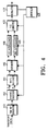
- FIG. 4 illustrates a structure of a transmitter in an HSDPA mobile communication system according to a second embodiment of the present invention.
- a tail bit generator 410 receives transport data, and adds associated tail bits to the received transport data.
- a channel encoder 412 under the control of a controller 426, encodes the tail bits-added data received from the tail bit generator 410 using a predetermined code.
- the predetermined code refers to a code for outputting transport bits and error control bits of the transport bits.
- the transport bits are systematic bits (S)
- the error control bits are parity bits (P).
- the predetermined code includes a turbo code and a systematic convolutional code, as mentioned above.
- a rate matcher 414 performs rate matching by repeating and puncturing the coded bits from the channel encoder 412.
- a distributor 416 under the control of the controller 426, receives the systematic bits and the parity bits from the rate matcher 414, and distributes the systematic bits and the parity bits to a plurality of interleavers.
- First and second interleavers 418 and 420 receive the coded bits from the distributor 416, and interleave the received coded bits.
- the coded bits may be the systematic bits, the parity bits, or a mixture of the systematic bits and the parity bits.
- the distributor 416 is essential.
- an interleaver receiving the mixed bits of the systematic bits and the parity bits rearranges the coded bits such that the systematic bits having higher priority always exist in specific positions, before interleaving. This assists the receiver in performing a decoding operation, and the transmitter pre-notifies the receiver of the specific positions of the systematic bits.
- first and second interleavers 418 and 420 When the first and second interleavers 418 and 420 have a variable length, they are controlled by the controller 426. That is, when the first and second interleavers 418 and 420 have a variable length, the lengths of the first and second interleavers 418 and 420 are determined by the controller 426.
- a parallel-to-serial (P/S) converter 422 under the control of the controller 426, receives in parallel the interleaved coded bits output from the first interleaver 418 and the interleaved coded bits output from the second interleaver 420, and outputs the received coded bits in series. For example, when the coded bits having the higher priority are interleaved by the first interleaver 418 and the coded bits having the lower priority are interleaved by the second interleaver 420, the P/S converter 422 first outputs the coded bits received from the first interleaver 418 and then outputs the coded bits received from the second interleaver 420. This is to map the systematic bits having the higher priority to the bit positions having the higher reliability in a succeeding modulation process.
- a modulator 424 symbol-maps the coded bits from the P/S converter 422 according to a predetermined symbol pattern, and then the symbol-mapped coded bits are transmitted to the receiver. For example, when the modulator 424 uses the 16QAM modulation, the coded bits are subject to symbol mapping according to a symbol pattern [H,H,L,L]. However, when the modulator 424 uses the 64QAM modulation, the coded bits are subject to symbol mapping according to a symbol pattern [H,H,M,M,L,L].
- the controller 426 controls the overall operation of the transmitter according to the second embodiment of the present invention. First, the controller 426 determines a coding rate and a modulation mode to be used in the current radio channel state. The controller 426 controls the coding rate of the channel encoder (or turbo encoder) 412 based on the determined coding rate to be used, and controls the modulator 424 based on the determined modulation mode. In addition, the controller 426 controls a distribution pattern of the distributor 416 based on the determined coding rate and the determined modulation mode. For example, when the plurality of interleavers include the two interleavers 418 and 420, the controller 426 controls the distributor 416 to distribute the systematic bits and the parity bits into two bit groups (bit streams) having the same number of bits.
- One of the two bit groups is provided to the first interleaver 418, and the other bit group is provided to the second interleaver 420.
- the controller 426 controls the distributor 416 to distribute the systematic bits and the parity bits into three bit groups.
- the distributor 416 is not essential in this embodiment. The reason is because when the 1/2 symmetric coding rate is used, the number of systematic bits is identical to the number of parity bits, and thus the systematic bits are provided to the first interleaver 418 and the parity bits are provided to the second interleaver 420.
- first and second interleavers 418 and 420 support a variable length, although they use an asymmetric coding rate such as 3/4 coding rate. That is, the distributor 416 is essential only when the first and second interleavers 418 and 420 support the asymmetric coding rate and the fixed length.
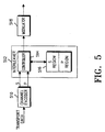
- FIG. 5 illustrates a structure of a transmitter in a CDMA mobile communication system according to a third embodiment of the present invention.
- the transmitter of FIG. 5 outputs coded symbols in series by an interleaver without a separate P/S converter.
- transport data is provided to a channel encoder 510 where the received transport data is encoded by a predetermined code. That is, the channel encoder 510 outputs systematic bits (S bits), which are actual transport data, and parity bits (P bits) for error controlling of the transport data.
- S bits and the P bits from the channel encoder 510 are provided to a controller 514 that is part of an interleaver 512.
- the controller 514 assigns a predetermined address to the S bits provided from the channel encoder 510, and sequentially stores the S bits in an S region of a memory 516.
- the controller 514 assigns a predetermined address to the P bits provided from the channel encoder 510, and sequentially stores the P bits in a P region of the memory 516.
- the controller 514 performs a control operation of transporting the S bits and the P bits stored in the memory 516. Specifically, the controller 514 analyzes the coding rate used by the channel encoder 510 to transmit the S bits and the P bits stored in the memory 516, and also analyzes the modulation mode to be used by a modulator 518. After determining the coding rate and the modulation mode through the analysis, the controller 514 reads the S bits and the P bits stored in the memory 516 based on the determined coding rate and modulation mode.
- the controller 514 when the determined coding rate is a symmetric coding rate 1/2 and the determined modulation mode is 16QAM or 64QAM, the controller 514 repeatedly alternately accesses the S region and the P region of the memory 516 in the same ratio, and outputs the same number of the S bits and the P bits. That is, the controller 514 first reads 2 (or 3) S bits by accessing the S region, and then reads 2 (or 3) P bits by accessing the P region. In the case of 2 bits, the 2 S bits and the 2 P bits output from the controller 514 are provided to the modulator 518 where the S bits and the P bits are subject to 16QAM modulation. Specifically, the 2 S bits are mapped to the 2 H-bit positions in the symbol pattern [H,H,L,L] defined for the 16QAM modulation, and the 2 P bits are mapped to the 2 L-bit positions in the symbol pattern.
- the controller 514 outputs the S bits and the P bits in a ratio of 3:1 by accessing the P region of the memory 516 once while accessing the S region 3 times.
- the 3 S bits and the 1 P bit output from the controller 514 are provided to the modulator 518 where the S bits and the P bit are subject to 16QAM modulation.
- the 2 S bits are mapped to the 2 H-bit positions in the symbol pattern [H,H,L,L] defined for the 16QAM modulation, and the remaining 1 S bit and the 1 P bit are mapped to the 2 L-bit positions in the symbol pattern.
- the controller 514 outputs the S bits and the P bits by accessing the S region and the P region of the memory 516 in a predetermined ratio.
- the total access number of the memory 516 is a value that can be divided by 2 (for QPSK), 3 (for 8PSK), 4 (for 16QAM) and 6 (for 64QAM).
- the S bits and the P bits output from the controller 514 are provided to the modulator 518, where the provided bits are subject to 64QAM modulation.
- the modulator 518 maps the first 2 S bits to the 2 H-bit positions in the symbol pattern [H,H,M,M,L,L] defined for the 64QAM modulation, maps the remaining 2 S bits to the 2 M-bit positions in the symbol pattern, and maps the 2 P bits to the 2 L-bit positions in the symbol pattern.
- the modulator 518 maps the first 2 S bits to the 2 H-bit positions in the symbol pattern [H,H,M,M,L,L] defined for the 64QAM modulation, maps the next 2 S bits to the 2 M-bit positions in the symbol pattern, and maps the remaining 1 S bit and the 1 P bit to the 2 L-bit positions in the symbol pattern.
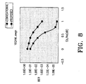
- FIG. 7 illustrates simulation results obtained when the simulation is performed using an encoder and a decoder both supporting 64QAM modulation according to an embodiment of the present invention.
- FIGs. 7 and 8 prove the effects of the invention. While the simulations were performed in a controlled setting, they are sufficient to show the beneficial effects of the invention. The simulation results of FIGs.
- FIGs. 7 and 8 show a comparison between a bit error rate (BER) and a bit-to-noise ratio (E b /N o ).
- BER bit error rate
- E b /N o bit-to-noise ratio
- the invention shows an increase in a gain of about 0.4dB or over for both the 16QAM and the 64QAM as compared with the prior art.
- the simulation results of FIGs. 7 and 8 were obtained in the simulation condition where AWGN (Additive White Gaussian Noise) exists, turbo encoder input block size of 5114 bits, coding rate of 1/2, and the interleavers with a fixed length are used.
- AWGN Additional White Gaussian Noise
- the present invention maps the bits having higher priority to the bit positions having higher reliability, thereby obtaining superior transportation efficiency in the technical fields of error control coding, modulation/demodulation and data transportation.
- the invention can be applied not only to the transceiver of the existing wired/wireless communication system, but also to the transceiver of the 3 rd generation mobile communication system, IMT-2000 system, thus improving the overall system performance. This is achieved by modulating (mapping) the bits having higher priority with the bits having higher reliability, which are less affected by the noises and environments. That is, compared with the conventional system, the system according to the present invention has a lower bit error rate (BER) and improved system performance.
- BER bit error rate
Abstract
Description
- This application claims priority to an application entitled "Apparatus and Method for Transmitting/Receiving Data in a CDMA Mobile Communication System" filed in the Korean Industrial Property Office on April 4, 2001 and assigned Serial No. 2001-17925, the contents of which are hereby incorporated by reference.
- The present invention relates generally to an apparatus and method for transmitting/receiving data in a CDMA (Code Division Multiple Access) mobile communication system, and in particular, to a data transmission/reception apparatus and method for improving reliability of transport data bits.
- In a communication system, it is actually impossible to receive a transmitted signal without any distortions or noises. In particular, when the signal is transmitted/received over a wireless network, the effects of the distortions or noises are more serious as compared with when the signal is transmitted/received over a wired network.
- Therefore, many efforts have been made to minimize the effects of the distortions or noises. An error control coding technique has been proposed as a typical method of minimizing the effects of the distortions or noises. Codes used for the error control coding technique are classified into a memoryless code and a memory code. For example, the memoryless code includes a linear block code, while the memory code includes a convolutional code and a turbo code. A device for generating such codes is called a "channel encoder", and its outputs can be divided into systematic bits and parity bits based on the error control coding technique. The turbo code is a code typically used for the error control coding technique that separates its outputs into the systematic bits and the parity bits. In addition to the turbo code, there exists a systematic convolutional code of the convolutional code, as a code used for the error control coding technique.
- Herein, the "systematic bits" mean an actual information signal, while the "parity bits" mean a supplemental signal added to correct a possible error which occurred during transportation in a decoding process. However, even though a signal is subjected to the error control coding, if a burst error occurs in the systematic bits or the parity bits, it is not easy to correct the burst error. Such a phenomenon frequently occurs while the signal passes through a fading channel, and an "interleaving" technique is typically used to prevent this phenomenon. The interleaving technique disperses a damaged part in several places rather than concentrating it on a single place, thereby complementing the error control coding technique.
- Such interleaved signal is subject to mapping in a symbol unit in a digital modulator. The number of bits included in one symbol increases with the order of the modulator. Particularly, in the case of high-order modulation of over 16QAM (16-ary Quadrature Amplitude Modulation), one symbol includes information of over 4 bits, and the bits can be classified according to reliability. Here, the "reliability" can be represented by a probability that the bit values will be changed during transportation. For example, when one 16QAM-modualted symbol is subject to mapping on coordinates, information of leading two bits in the symbol has higher reliability since the leading two bits determine a quadrant of the coordinates, to which the symbol is to be mapped. This means that there is a lower probability that the information of the leading two bits will be changed during transportation. However, information of the remaining two bits in the symbol has lower reliability, since the remaining two bits determine one of the four regions obtained by dividing the determined quadrant. This means that there is a higher probability that the information of the remaining two bits will be changed during transportation. That is, of at least 3 bits included in one symbol, the bits determining a wider region have higher reliability and the bits determining a narrower region have lower reliability.
- A transmitter of a common HSDPA (High-Speed Downlink Packet Access) radio communication system is comprised of a channel encoder, an interleaver and a modulator, as illustrated in FIG. 1.
- Referring to FIG. 1, a
tail bit generator 110 receives N transport blocks and adds associated tail bits to the respective transport blocks. Achannel encoder 112 encodes the N tail bit-added transport blocks from thetail bit generator 110 and outputs coded symbols. Thechannel encoder 112 has at least one coding rate in order to encode the N transport blocks. The coding rate may be 1/2 or 3/4. When thechannel encoder 112 supports a plurality of coding rates through symbol puncturing or symbol repetition using a 1/6 or 1/5 mother encoder, an operation of selecting a coding rate from the available coding rates is required. In FIG. 1, thechannel encoder 112 determines (selects) the coding rate under the control of acontroller 120. - A rate matcher 114 rate-matches the coded symbols from the
channel encoder 112. The rate matching is performed by repeating or puncturing the coded symbols, when a transport channel is subject to multiplexing or when the number of the output symbols of thechannel encoder 112 is not identical to the number of symbols transported over a radio channel. Aninterleaver 116 interleaves the rate-matched coded symbols from the rate matcher 114. The interleaving is performed to minimize a possible data loss during transportation. An M-ary modulator 118 modulates the interleaved coded symbols by QPSK (Quadrature Phase Shift Keying), 8PSK (8-ary Phase Shift Keying), 16QAM or 64QAM modulation. Thecontroller 120 controls an operation of the channel encoder (or turbo encoder) 112 and a modulation mode of themodulator 118 according to a current state of the radio channel. The HSDPA radio communication system uses AMCS (Adaptive Modulation and Coding Scheme) for thecontroller 120 in order to select the modulation modes (QPSK, 8PSK, 16QAM and 64QAM) according to the radio environment. Though not illustrated in the drawing, the CDMA mobile Communication system spreads transport data using a Walsh code W and an orthogonal code PN, so that a corresponding mobile terminal (or UE (User Equipment)) can identify a channel and a base station (or Node B) transmitting the data. - The structure of the transmitter has been described on the assumption that coded symbols are not divided into the systematic bits and the parity bits. However, the coded symbols output from the
channel encoder 112 of the transmitter can be divided into the systematic bits and the parity bits. Of course, the systematic bits and the parity bits output from thechannel encoder 112 have different priorities. Namely, in the case where errors occur in the transport data at a given rate, it is possible to perform relatively correct decoding when the errors occur in the parity bits rather than in the systematic bits. The reason is, as stated above, because the systematic bits are actual data bits while the parity bits are supplemental bits added to correct errors occurred during transportation in a decoding process. - However, the
interleaver 116 of the conventional transmitter in the communication system performs interleaving regardless of the priorities of the systematic bits and the parity bits. That is, the conventional transmitter performs symbol mapping irrespective of the systematic bits and the parity bits. - Hence, the conventional radio communication system has a high error occurrence probability regardless of the priorities of the systematic bits and the parity bits, when transporting data over the wireless network. Accordingly, there is a need for a technique capable of reducing a probability that errors will occur in the systematic bits having higher priority than the parity bits, thereby improving system performance.
- It is, therefore, an object of the present invention to provide a data transmission/reception apparatus and method for improving performance of a radio communication system.
- It is another object of the present invention to provide a data transmission/reception apparatus and method having higher reliability in a radio communication system.
- It is further another object of the present invention to provide a data transmission/reception apparatus and method for receiving bits having higher priority at a receiver having a higher reception probability in a radio communication system.
- It is yet another object of the present invention to provide a data transmission/reception apparatus and method for mapping data bits to symbol bit positions having different reliabilities according to priorities of transport data bits.
- It is still another object of the present invention to provide a data reception apparatus and method for receiving data bits mapped to symbol bit positions having different reliabilities according to priorities of transport data bits.
- It is still another object of the present invention to provide a data transmission apparatus and method for mapping data bits having higher priority to symbol bit positions having higher reliability, and mapping data bits having lower priority to symbol bit positions having lower reliability.
- It is still another object of the present invention to provide a data transmission apparatus and method for mapping systematic bits to symbol bit positions having higher reliability and parity bits to symbol bit positions having lower reliability.
- To achieve the above and other objects, the present invention provides a data transmission apparatus and method for dividing transport data bits into bits having higher priority and bits having lower priority, mapping the bits having higher priority to symbol bit positions having higher reliability, and mapping the bits having lower priority to symbol bit positions having lower reliability.
- Further, the present invention provides a data reception apparatus and method for demodulating received modulated symbols, dividing the demodulated coded bits into two coded bit groups according to priority, deinterleaving the coded bit groups using different deinterleavers, and decoding the deinterleaved coded bits.
- The above and other objects, features and advantages of the present invention will become more apparent from the following detailed description when taken in conjunction with the accompanying drawings in which:
- FIG. 1 illustrates a structure of a conventional transmitter in a CDMA communication system;
- FIG. 2 illustrates a structure of a transmitter in a CDMA mobile communication system according to a first embodiment of the present invention;
- FIG. 3 illustrates a structure of a receiver according to a first embodiment of the present invention;
- FIG. 4 illustrates a structure of a transmitter in a CDMA mobile communication system according to a second embodiment of the present invention;
- FIG. 5 illustrates a structure of a transmitter in a CDMA mobile communication system according to a third embodiment of the present invention;
- FIG. 6 illustrates an output format of the P/S converter in the transmitter according to an embodiment of the present invention;
- FIG. 7 illustrates simulation results obtained when the simulation is performed using 64QAM modulation according to an embodiment of the present invention; and
- FIG. 8 illustrates simulation results obtained when the simulation is performed using 16QAM modulation according to an embodiment of the present invention.
-
- A preferred embodiment of the present invention will be described herein below with reference to the accompanying drawings. In the following description, well-known functions or constructions are not described in detail since they would obscure the invention in unnecessary detail.
- In the following description, it will be assumed that the channel encoder supports a coding rate of 1/2 and 3/4, and the modulator supports QPSK, 8PSK, 16QAM and 64QAM. Shown in Table 1 are available encoding operations according to an embodiment of the present invention, when the assumption stated above is applied.
Coding Rate Modulation Mode 1/2 QPSK 8PSK 16QAM 64QAM 3/4 QPSK 8PSK 16QAM 64QAM - At the 1/2 coding rate (symmetric coding rate), the
channel encoder outputs 2 bits by receiving one input bit. One of the 2 output bits is an actual data bit, a systematic bit, while the remaining one bit is a parity bit for detecting and compensating for an error. However, at the 3/4 coding rate (asymmetric coding rate), the channel encoder outputs 4 bits by receiving 3 input bits. The 4 output bits are divided into 3 systematic bits and one parity bit. - A symbol pattern based on the 16QAM can be expressed as [H,H,L,L], and a symbol pattern based on the 64QAM can be expressed as [H,H,M,M,L,L]. In the symbol patterns, "H" represents a bit position having High reliability, "L" represents a bit position having Low reliability, and "M" represents a bit position having Medium reliability. The present invention aims at mapping the bits having relatively higher priority (e.g., systematic bits and tail bits) to the bit positions having higher reliability, and mapping the bits having relative lower priority (e.g., parity bits) to the bit positions having lower reliability, in performing symbol mapping on the coded bits according to a predetermined symbol pattern.
- Now, reference will be made to symbol mapping methods based on the 1/2 and 3/4 coding rates and the 16QAM and 64QAM modulations according to an embodiment of the present invention.
- First, when using the 1/2 coding rate and the 16QAM modulation, the transmitter maps 2 systematic bits to the 2 H-bit positions in the symbol pattern, and maps 2 parity bits to the 2 L-bit positions in the symbol pattern. In this case, it is preferable to use an interleaver with a fixed length.
- Second, when using the 3/4 coding rate and the 16QAM modulation, the transmitter can use either an interleaver with a fixed length or an interleaver with a variable length. When the interleaver with a fixed length is used, the interleaver for interleaving systematic bits is identical in length to the interleaver for interleaving parity bits. However, when the interleaver with a variable length is used, the interleaver for interleaving systematic bits may not be identical in length to the interleaver for interleaving parity bits.
- When using the interleaver with a fixed length, the transmitter maps the first 2 systematic bits to the 2 H-bit positions in the symbol pattern after interleaving, and maps the remaining 1 systematic bit and 1 parity bit to the 2 L-bit positions in the symbol pattern after interleaving. Therefore, when the interleaver has a fixed length, a separate structure for matching the numbers of input bits to the respective interleavers is required. Although the description has been made of an example where the coded bits are subject to interleaving in a unit of 2 bits, this may be varied depending on a length of the interleaver. That is, although the present invention will be described with reference to an example where the coded bits are subject to interleaving in a unit of 2 bits, it would be obvious to those skilled in the art that the coded bits may be subjected to interleaving in units of 4 or 8 bits.
- However, when using the interleaver with a variable length, the transmitter varies a length of the interleaver according to the number of the systematic bits and the number of the parity bits. That is, the transmitter interleaves 3 systematic bits and maps them to the 2 H-bit positions and the 1 H-bit position in the symbol pattern. Further, the transmitter maps 1 parity bit to the remaining 1 L-bit position in the symbol pattern. Although the description has been made of an example where the 2 systematic bits and the 1 parity bit are subject to interleaving, the number of the bits subjected to interleaving may be varied depending on a length of the interleaver. That is, when a length of the interleaver is 8, the coded bits may be subject to interleaving in a unit of 8 bits.
- Third, when using the 1/2 coding rate and the 64 QAM modulation, the transmitter maps 2 systematic bits to the 2 H-bit positions in the symbol pattern, and maps the remaining 1 systematic bit to the 1 M-bit position in the symbol pattern. Further, the transmitter maps 2 parity bits to the 2 L-bit positions in the symbol pattern and maps the remaining 1 parity bit to the remaining 1 M-bit position in the symbol pattern. In this case, it is preferable to use an interleaver with a fixed length.
- Fourth, when using the 3/4 coding rate and the 64QAM modulation, the transmitter may use either an interleaver with a fixed length or an interleaver with a variable length. When using the interleaver with a fixed length, transmitter determines a ratio of the systematic bits to the parity bits such that as many systematic bits as possible may be mapped to the bit positions having higher reliability in the symbol pattern.
- FIG. 2 illustrates a structure of a transmitter in a CDMA mobile communication system according to a first embodiment of the present invention. Referring to FIG. 2, a
channel encoder 210 receives transport data and encodes the received transport data using a predetermined code. The predetermined code refers to a code for outputting transport bits and error control bits of the transport bits, obtained by encoding the received data. For example, the transport bits are systematic bits (S), and the error control bits are parity bits (P). The predetermined code includes a turbo code and a systematic convolutional code, as mentioned above. - A
distributor 212 receives the systematic bits and the parity bits from thechannel encoder 210, and distributes the systematic bits and the parity bits to a plurality of interleavers. For example, when there exist twointerleavers distributor 212 distributes the systematic bits and the parity bits into two bit groups having the same number of bits. For example, when the 3/4 coding rate and the 16QAM modulation are used, thedistributor 212 distributes the 2 S bits to thefirst interleaver 214, and distributes the remaining 1 S bit and the 1 P bit to thesecond interleaver 216. As a result, one of two bit groups (or bit streams) is provided to thefirst interleaver 214, while the other bit group is provided to thesecond interleaver 216. However, when the transmitter uses a systematic coding rate such as 1/2 coding rate, thedistributor 212 is not essential in the first embodiment. The reason is because when the 1/2 symmetric coding rate is used, the number of systematic bits is identical to the number of parity bits, and thus the systematic bits are provided to thefirst interleaver 214 and the parity bits are provided to thesecond interleaver 216. Thedistributor 212 is also not essential even when the first and second interleavers 214 and 216 support a variable length, although they use an asymmetric coding rate such as 3/4 coding rate. That is, thedistributor 212 is essential only when the first and second interleavers 214 and 216 support the asymmetric coding rate and the fixed length. - The first and second interleavers 214 and 216 receive the coded bits from the
distributor 212 or thechannel encoder 210, and interleave the received coded bits. The coded bits may be the systematic bits, the parity bits, or a mixture of the systematic bits and the parity bits. When the received coded bits are the mixed bits of the systematic bits and the parity bits, thedistributor 212 is essential. In this case, an interleaver receiving the mixture of the systematic bits and the parity bits rearrange the coded bits such that the systematic bits having higher priority always exist in specific positions, before interleaving. This assists the receiver in performing a decoding operation, and the specific positions of the systematic bits are previously notified to the receiver by the transmitter. - The sum of a length of the
first interleaver 214 and a length of thesecond interleaver 216 are a value that can be divided by 2 (for QPSK), 3 (for 8PSK), 4 (for 16QAM) and 6 (for 64QAM). As an example of this condition, when the total length Ltot of the interleavers is 144 bits, the following condition is satisfied. - A parallel-to-serial (P/S)
converter 218 receives in parallel the interleaved coded bits output from thefirst interleaver 214 and the interleaved coded bits output from thesecond interleaver 216, and outputs the received coded bits in series. For example, when the coded bits having the higher priority are interleaved by thefirst interleaver 214 and the coded bits having the lower priority are interleaved by thesecond interleaver 216, the P/S converter 218 first outputs the coded bits received from thefirst interleaver 214 and then outputs the coded bits received from thesecond interleaver 216. This is to map the systematic bits having the higher priority to the bit positions having the higher reliability in a succeeding modulation process. An output format of the P/S converter 218 is illustrated in FIG. 6. In FIG. 6, "H Parts" represent the bits having higher priority, while "L Parts" represent the bits having lower priority. The H parts and the L parts are symmetrical for the interleaver with a fixed length, and asymmetrical for the interleaver with a variable length. - A
modulator 220 symbol-maps the coded bits from the P/S converter 218 according to a predetermined symbol pattern. For example, when themodulator 220 uses the 16QAM modulation, the coded bits are subject to symbol mapping according to the symbol pattern [H,H,L,L]. However, when themodulator 220 uses the 64QAM modulation, the coded bits are subject to symbol mapping according to the symbol pattern [H,H,M,M,L,L]. - Though not illustrated in FIG. 2, a transmitter in the CDMA mobile communication system may further include a rate matcher for performing rate matching by repeating and puncturing the coded bits from the
channel encoder 210. - FIG. 3 illustrates a structure of a receiver according to a first embodiment of the present invention. The receiver corresponds to the transmitter of FIG. 2. Referring to FIG. 3, a
demodulator 310 receives data transported from the transmitter, and demodulates the received data according to a demodulation mode corresponding to the modulation mode used by themodulator 220 of the transmitter. - A serial-to-parallel (S/P)
converter 312 receives in series the demodulated coded bits from thedemodulator 310, and outputs in parallel the received coded bits by switching. For example, when themodulator 220 in the transmitter uses the 16QAM modulation, the S/P converter 312 outputs first 2 bits to afirst deinterleaver 314 and the next 2 bits to asecond deinterleaver 316, by switching the coded bits in a 2-bit unit. When themodulator 220 in the transmitter uses the 64QAM modulation, the S/P converter 312 outputs first 3 bits to thefirst deinterleaver 314 and the next 3 bits to thesecond deinterleaver 316, by switching the coded bits in a 3-bit unit. However, when the transmitter uses an asymmetric coding rate and interleavers having a variable length, the S/P converter 312 recognizes the variable length based on previously received information. In this manner, the S/P converter 312 outputs as many coded bits as a length of thefirst interleaver 214 in the transmitter to thefirst deinterleaver 314, and outputs as many coded bits as a length of thesecond interleaver 216 in the transmitter to thesecond deinterleaver 316. - The first and second deinterleavers 314 and 316 deinterleave the coded bits provided from the S/
P converter 312. Operations of the first and second deinterleavers 314 and 316 correspond to operations of the fast and second interleavers 214 and 216 in the transmitter. That is, since the first and second deinterleavers 314 and 316 (based on a prior storage and/or exchange of information) recognize the interleaving patterns performed by the first and second interleavers 214 and 216 of the transmitter, the same interleaving pattern is pre-arranged for the transmitter and the receiver. For example, the transmitter may previously inform the receiver of the interleaving pattern information as system information before call setup. - A
classifier 318 classifies the deinterleaved coded bits provided from the first and second deinterleavers 314 and 316. The coded bits may be systematic bits, parity bits or a mixture of the systematic bits and the parity bits. When the coded bits are the mixed bits of the systematic bits and the parity bits, theclassifier 318 is an essential element. In this case, among the coded bits output from a deinterleaver for deinterleaving the mixed bits of the systematic bits and the parity bits, the systematic bits having higher priority will always exist in specific positions. By prior arrangement, the transmitter and the receiver will agree on the positions of the systematic bits, analogous to the interleaving pattern information. For example, the transmitter may previously inform the receiver of the systematic bit position information as system information. For example, when the coded bits having higher priority are deinterleaved by thefirst deinterleaver 314 and the coded bits having lower priority are deinterleaved by thesecond deinterleaver 316, theclassifier 318 may first output the deinterleaved coded bits from thefirst deinterleaver 314 and then output the deinterleaved coded bits from thesecond deinterleaver 316. However, theclassifier 318 is not an essential element when the transmitter uses the symmetric coding rate such as 1/2 coding rate. - A
channel decoder 320 receives the coded bits from theclassifier 318 or the coded bits from the first and second deinterleavers 314 and 316, and decodes the received coded bits according to a predetermined decoding method, thereby outputting desired decoded bits. For the predetermined decoding method, a method for receiving systematic bits and parity bits and then decoding the systematic bits is used, and the decoding method is determined based on the encoding method of the transmitter. - Operations of the first embodiment of the present invention will be described in detail herein below with reference to FIGs. 2 and 3.
- First, operations of the transmitter will be described in detail with reference to FIG. 2. Operations of the transmitter according to the first embodiment of the present invention can be divided into three operations depending on the coding rate and whether the transmitter uses interleavers with a fixed length or interleavers with a variable length. The three operations include (1) a first operation where the transmitter uses the symmetric coding rate, (2) a second operation where the transmitter uses the asymmetric coding rate and the interleavers with a fixed length, and (3) a third operation where the transmitter uses the asymmetric coding rate and the interleavers with a variable length. A detailed description of the three operations according to the first embodiment of the present invention will be given below.
- An operation of the transmitter using the symmetric coding rate will be described in detail below. Transport data is provided to the
channel encoder 210 where it is encoded by a specific code. That is, thechannel encoder 210 outputs systematic bits (S bits), which are actual transport data, and parity bits (P bits) for error controlling of the transport data, through encoding. For example, when thechannel encoder 210 uses the symmetric coding rate such as 1/2 coding rate, it outputs the S bits and the P bits in the same ratio. The S bits provided from thechannel encoder 210 are provided to thefirst interleaver 214, while the P bits provided from thechannel encoder 210 are provided to thesecond interleaver 216. - Therefore, the S bits are interleaved by the
first interleaver 214 and the P bits are interleaved by thesecond interleaver 216. The interleaving pattern of the first and second interleavers 214 and 216 is previously determined, and by pre-arrangement the determined interleaving pattern is recognized by the receiver. - The interleaved S and P bits from the first and second interleavers 214 and 216 are provided in parallel to the P/
S converter 218. The interleaved S bits and P bits provided in parallel to the P/S converter 218 are output in series. Preferably, the P/S converter 218 first outputs a predetermined number of the interleaved S bits and then outputs a predetermined number of the interleaved P bits. - The interleaved S and P bits from the P/
S converter 218 are provided to themodulator 220 where they are subject to symbol mapping according to the predetermined symbol pattern and then transmitted to the receiver of Fig. 3. For example, when the modulation mode of themodulator 220 is 16QAM, the predetermined symbol pattern is defined as [H,H,L,L]. Therefore, themodulator 220 maps the 2 interleaved S bits to the H-bit positions in the symbol pattern and the 2 interleaved P bits to the L-bit positions in the symbol pattern, and then the symbol-mapped bits are transmitted to the receiver. However, when the modulation mode of themodulator 220 is 64QAM, the predetermined symbol pattern is defined as [H,H,M,M,L,L]. Therefore, themodulator 220 maps 3 interleaved S bits to 2 H-bit positions and 1 M-bit position in the symbol pattern, and maps 3 interleaved P bits to the remaining 1 M-bit position and 2 L-bit positions in the symbol pattern. The symbol-mapped bits are then transmitted to the receiver. - An operation of the receiver using the symmetric coding rate will be described in detail below. Data received from the transmitter is provided to the
demodulator 310 where the received data is demodulated in coded bits according to a demodulation mode corresponding to the modulation mode used by themodulator 220 of the transmitter. The demodulated coded bits from thedemodulator 310 are provided in series to the S/P converter 312, and the S/P converter 312 outputs the received coded bits in parallel. For example, when themodulator 220 of the transmitter uses 16QAM modulation, the S/P converter 312 outputs the first 2 bits to thefirst deinterleaver 314 and the next 2 bits to thesecond deinterleaver 316. However, when themodulator 220 of the transmitter uses 64QAM modulation, the S/P converter 312 outputs the first 3 bits to thefirst deinterleaver 314 and the next 3 bits to thesecond deinterleaver 316. - The coded bits from the S/
P converter 312 are classified into two bit groups, and the classified bit groups are provided to the first and second deinterleavers 314 and 316, where the bit groups are subject to deinterleaving. The deinterleaving operations of the first and second deinterleavers 314 and 316 correspond to the interleaving operations performed by the first and second interleavers 214 and 216 of the transmitter. That is, the first and second deinterleavers 314 and 316 perform deinterleaving according to the interleaving pattern performed by the first and second interleavers 214 and 216 of the transmitter. - The deinterleaved coded bits from the first and second deinterleavers 314 and 316 are provided to the
decoder 320 where the coded bits are decoded into desired received bits according to a predetermined decoding method. For the predetermined decoding method, a method for receiving S bits and P bits and then decoding the S bits is used, and the decoding method is determined based on the encoding method of the transmitter. - An operation of the transmitter using the asymmetric coding rate and the interleavers with a fixed length will be described in detail below. Transport data is provided to the
channel encoder 210 where it is encoded by a specific code. That is, thechannel encoder 210 outputs systematic bits (S bits), which are actual transport data, and parity bits (P bits) for error controlling of the transport data, through encoding. For example, when thechannel encoder 210 uses the asymmetric coding rate such as 3/4 coding rate, it outputs the S bits and the P bits in a ratio based on the 3/4 coding rate. That is, thechannel encoder 210 outputs 3 S bits and 1 P bit. - The S bits and the P bits from the
channel encoder 210 are provided to thedistributor 212 where they are divided into two bit groups in the same ratio. That is, when 16QAM modulation is used, thedistributor 212 provides 2 S bits to thefirst interleaver 214, and provides the remaining 1 S bit and 1 P bit to thesecond interleaver 216. - A description will be made as to how the
distributor 212 operates in two possible cases. In a first case where the number of the systematic bits is larger than the number of the parity bits, thedistributor 212 fills thefirst interleaver 214 with the systematic bits, and fills thesecond interleaver 216 with the remaining systematic bits along with the parity bits. In a second case where the number of the systematic bits is less than the number of the parity bits, thedistributor 212 fills thefirst interleaver 214 with the systematic bits, fills the remaining part of thefirst interleaver 214 with parity bits, and fills thesecond interleaver 216 with the remaining parity bits. - Therefore, the 2 S bits are interleaved by the
first interleaver 214, and the remaining 1 S bit and the 1 P bit are interleaved by thesecond interleaver 216. The interleaving pattern of the first and second interleavers 214 and 216 is previously set, and the same interleaving pattern is previously set in the receiver. Further, provided with the S bit and the P bit from thedistributor 212, thesecond interleaver 216 determines the S bit position before interleaving based on a previously determined pattern that is the same as the receiver, so that the receiver can efficiently classify the S bit and the P bit in the decoding process. For example, the S bit to be interleaved by thesecond interleaver 216 is located in a front position before interleaving, so that the receiver can estimate a bit located in the front position as the S bit after deinterleaving. - The S bits interleaved by the
first interleaver 214, and the S bit and the P bit interleaved by thesecond interleaver 216 are provided in parallel to the P/S converter 218. The P/S converter 218 outputs in series the provided interleaved S bits and P bit and the provided interleaved S bit and P bit. Preferably, the P/S converter 218 first outputs the output bits of thefirst interleaver 214 and then outputs the output bits of thesecond interleaver 216. - The interleaved S bits and the interleaved S bit and P bit from the P/
S converter 218 are provided to themodulator 220 where they are subject to symbol mapping according to the predetermined symbol pattern and then are transmitted to the receiver of Fig. 3. For example, when the modulation mode of themodulator 220 is 16QAM, the predetermined symbol pattern is defined as [H,H,L,L]. Therefore, themodulator 220 maps the 2 interleaved S bits to the H-bit positions in the symbol pattern and the 2 interleaved bits of the S bit and the P bit to the L-bit positions in the symbol pattern, and the symbol-mapped bits are then transmitted to the receiver. However, when the modulation mode of themodulator 220 is 64QAM, the predetermined symbol pattern is defined as [H,H,M,M,L,L]. Therefore, themodulator 220 maps 3 S bits interleaved by thefirst interleaver 214 to 2 H-bit positions and 1 M-bit position in the symbol pattern, and maps 3 P bits interleaved by thesecond interleaver 216 to the remaining 1 M-bit position and 2 L-bit positions in the symbol pattern. The symbol-mapped bits are then transmitted to the receiver. - In this case, since the two interleavers have a fixed size, it is not necessary to vary the length of the interleavers according to the coding rate. Thus, it is simple to implement the interleavers. However, when there exist three or more reliability levels as in the high order modulation of over 64QAM, there is a case where an optimal condition is not satisfied. The "optimal condition" refers to a condition in which the bits having higher priority are always mapped to the bit positions having higher reliability. In the optimal condition, if the number of the S bits is larger than the number of P bits, the remaining S is provided to the second interleaver and then interleaved along with the P bit. Accordingly, though the S bits interleaved by the
first interleaver 214 are mapped to the bit positions having the higher reliability, the S bit provided to thesecond interleaver 216 may be mapped to the bit position having lower reliability. To avoid this, it is possible to increase the number of interleavers to cover the 3 different reliability levels. Increasing the number of the interleavers is mere extension of the present invention, so the detailed description will not be given in order not to obscure the gist of the present invention. However, even the transmitter using the two interleavers with a fixed length demonstrates better performance than the conventional transmitter. - An operation of the receiver using the asymmetric coding rate and the interleavers with a fixed length will be described in detail below. Data received from the transmitter is provided to the
demodulator 310 where the received data is demodulated in coded bits according to a demodulation mode corresponding to the modulation mode used by themodulator 220 of the transmitter. The demodulated coded bits from thedemodulator 310 are provided in series to the S/P converter 312, and the S/P converter 312 outputs the received coded bits in parallel. For example, when themodulator 220 of the transmitter uses 16QAM modulation, the S/P converter 312 outputs the first 2 bits to thefirst deinterleaver 314 and the next 2 bits to thesecond deinterleaver 316. In this case, the first 2 bits are comprised of only the systematic bits, and the next 2 bits are comprised of an S bit and a P bit. However, when themodulator 220 of the transmitter uses 64QAM modulation, the S/P converter 312 outputs the first 3 bits to thefirst deinterleaver 314 and the next 3 bits to thesecond deinterleaver 316. - The coded bits from the S/
P converter 312 are classified into two bit groups, and the classified bit groups are provided to the first and second deinterleavers 314 and 316, where the bit groups are subject to deinterleaving. The deinterleaving operations of the first and second deinterleavers 314 and 316 correspond to the interleaving operations performed by the first and second interleavers 214 and 216 of the transmitter. That is, the first and second deinterleavers 314 and 316 perform deinterleaving according to the interleaving pattern performed by the first and second interleavers 214 and 216 of the transmitter. - The deinterleaved coded bits from the first and second deinterleavers 314 and 316 are provided to the
classifier 318 where the coded bits are classified into the S bits and the P bits. As the output bits of thesecond deinterleaver 316 are mixed bits of the S bit and the P bits, by pre-arrangement along with the transmitter, theclassifier 318 recognizes the position where the S bit among the deinterleaved bits exists. - The coded bits from the
classifier 318 are provided to thedecoder 320 where the coded bits are decoded into desired received bits according to a predetermined decoding method. For the predetermined decoding method, a method for receiving S bits and P bits and then decoding the S bits is used. The decoding method is determined based on the encoding method of the transmitter. - An operation of the transmitter using the asymmetric coding rate and the interleavers with a variable length will be described in detail below. Transport data is provided to the
channel encoder 210 where it is encoded by a specific code. That is, thechannel encoder 210 outputs systematic bits (S bits), which are actual transport data, and parity bits (P bits) for error controlling of the transport data, through encoding. In this example, when thechannel encoder 210 uses the asymmetric coding rate such as 3/4 coding rate, it outputs the S bits and the P bits in a different ratio based on the 3/4 coding rate. That is, thechannel encoder 210 outputs 3 S bits and 1 P bit. The S bits from thechannel encoder 210 are provided to thefirst interleaver 214, and the P bits from thechannel encoder 210 are provided to thesecond interleaver 216. - Therefore, the S bits are interleaved by the
first interleaver 214, and the P bits are interleaved by thesecond interleaver 216. The interleaving pattern and length of the first and second interleavers 214 and 216 are previously determined, and the determined interleaving pattern and length are by pre-arrangement also recognized by the receiver. The length can be determined based on a ratio of the S bits to the P bits. - The interleaved S bits and P bits from the first and second interleavers 214 and 216 are provided in parallel to the P/
S converter 218. The P/S converter 218 outputs the provided interleaved S bits and P bits in series. Preferably, the P/S converter 218 outputs the interleaved S bits and P bits such that the interleaved S bits are mapped to the bit positions having higher reliability. - The interleaved S bits and the interleaved P bits from the P/
S converter 218 are provided to themodulator 220 where they are mapped to predetermined bit positions and then transmitted to the receiver of Fig. 3. For example, when a length of thefirst interleaver 214 receiving the S bits is 18 bits long and a length of thesecond interleaver 216 receiving the P bits is 6 bits long, a symbol mapping operation performed by themodulator 220 is as follows. - First, when the modulation mode of the
modulator 220 is 16QAM, the predetermined symbol pattern is defined as [H,H,L,L]. Therefore, themodulator 220 maps the 2 interleaved S bits to the H-bit positions in the symbol pattern, maps the remaining 1 S bit and 1 P bit to the L-bit positions in the symbol pattern, and then transmits the symbol-mapped bits to the receiver. - Next, when the modulation mode of the
modulator 220 is 64QAM, the predetermined symbol pattern is defined as [H,H,M,M,L,L]. Therefore, in a first modulation process, themodulator 220 symbol-maps the S bits and the P bits according to the symbol pattern in a ratio of 4:2. In a second modulation process, themodulator 220 symbol-maps the S bits and the P bits according to the symbol pattern in a ratio of 5:1. In a third modulation process, themodulator 220 symbol-maps the S bits and the P bits according to the symbol pattern in a ratio of 4:2. In a fourth modulation process, themodulator 220 symbol-maps the S bits and the P bits according to the symbol pattern in a ratio of 5:1. That is, in the first and third modulation processes where the ratio of the S bits to the P bits is 4:2, themodulator 220 maps the 2 S bits to the 2 H-bit positions in the symbol pattern, maps the remaining 2 S bits to the 2 M-bit positions in the symbol pattern, and maps the 2 P bits to the 2 L-bit positions in the symbol pattern. The symbol-mapped bits are then transmitted to the receiver. In the second and fourth modulation processes where the ratio of the S bits to the P bits is 5:1, themodulator 220 maps the 2 S bits to the 2 H-bit positions in the symbol pattern, maps the remaining 2 S bits to the 2 M-bit positions in the symbol pattern, and maps the last 1 S bit and the 1 P bit to the 2 L-bit positions in the symbol pattern. The symbol-mapped bits are then transmitted to the receiver. - Shown in Table 2 are the modulation processes performed by the transmitter using the asymmetric coding rate and the 64QAM modulation.
H H M M L L 1st Modulation S S S S P P 2nd Modulation S S S S S P 3rd Modulation S S S S P P 4th Modulation S S S S S P - When the length of the interleavers is varied as described above, it is necessary to disadvantageously control the size (length) of the two interleavers according to the coding rate. It is nonetheless possible to perform symbol mapping in an optimal condition regardless of the coding rate and the order of the modulator. In addition, since it is not necessary to distribute the S bits and the P bits to the two interleavers in a specific ratio, the transmitter does not require the
distributor 212. - An operation of the receiver using the asymmetric coding rate and the interleavers with a variable length will be described in detail below. Data received from the transmitter is provided to the
demodulator 310 where the received data is demodulated in coded bits according to a demodulation mode corresponding to the modulation mode used by themodulator 220 of the transmitter. The demodulated coded bits from thedemodulator 310 are provided in series to the S/P converter 312, and the S/P converter 312 outputs the received coded bits in parallel. When the transmitter uses the asymmetric coding rate and the interleavers with a variable length, the S/P converter 312 by pre-arrangement will recognize the varying length. Thus, the S/P converter 312 outputs as many coded bits as a length of thefirst interleaver 214 in the transmitter to thefirst deinterleaver 314, and outputs as many coded bits as a length of thesecond interleaver 216 in the transmitter to thesecond deinterleaver 316. - When the
modulator 220 of the transmitter uses 16QAM modulation, the S/P converter 312 outputs the first 3 bits to thefirst deinterleaver 314 and the next 1 bits to thesecond deinterleaver 316. However, when themodulator 220 of the transmitter uses 64QAM modulation, the S/P converter 312 divides the coded bits from thedemodulator 310 into a series output of S bits and P bits according to a ratio of the S bits and the P bits used by the P/S converter 218 of the transmitter. The ratio can be determined based on a ratio of a length of thefirst interleaver 214 to a length of thesecond interleaver 216 of the transmitter. - For example, when the P/
S converter 218 of the transmitter has used 4:2, 5:1, 4:2, and 5:1 ratios of the S bits to the P bits, i.e., ratios of the length of thefirst interleaver 214 to the length of thesecond interleaver 216, the S/P converter 312 outputs the first 4 bits to thefirst deinterleaver 314 and the next 2 bits to thesecond deinterleaver 316, in first and third processes. In second and fourth processes, the S/P converter 312 outputs the first 5 bits to thefirst deinterleaver 314 and the next 1 bit to thesecond deinterleaver 316. - The coded bits from the S/
P converter 312 are classified into two bit groups, and the classified bit groups are provided to the first and second deinterleavers 314 and 316, where the bit groups are subject to deinterleaving. The deinterleaving operations of the first and second deinterleavers 314 and 316 correspond to the interleaving operations performed by the first and second interleavers 214 and 216 of the transmitter. That is, the first and second deinterleavers 314 and 316 perform deinterleaving according to the interleaving pattern performed by the first and second interleavers 214 and 216 of the transmitter. - The deinterleaved coded bits from the first and second deinterleavers 314 and 316, previously divided into the S bits and the P bits by the S/
P converter 312, are provided to thedecoder 320 where the coded bits are decoded into desired received bits according to a predetermined decoding method. For the predetermined decoding method, a method for receiving S bits and P bits and then decoding the S bits is used. The decoding method is determined based on the encoding method of the transmitter. - FIG. 4 illustrates a structure of a transmitter in an HSDPA mobile communication system according to a second embodiment of the present invention. Referring to FIG. 4, a
tail bit generator 410 receives transport data, and adds associated tail bits to the received transport data. Achannel encoder 412, under the control of acontroller 426, encodes the tail bits-added data received from thetail bit generator 410 using a predetermined code. The predetermined code refers to a code for outputting transport bits and error control bits of the transport bits. For example, the transport bits are systematic bits (S), and the error control bits are parity bits (P). The predetermined code includes a turbo code and a systematic convolutional code, as mentioned above. - A
rate matcher 414 performs rate matching by repeating and puncturing the coded bits from thechannel encoder 412. Adistributor 416, under the control of thecontroller 426, receives the systematic bits and the parity bits from therate matcher 414, and distributes the systematic bits and the parity bits to a plurality of interleavers. - First and second interleavers 418 and 420 receive the coded bits from the
distributor 416, and interleave the received coded bits. The coded bits may be the systematic bits, the parity bits, or a mixture of the systematic bits and the parity bits. When the received coded bits are the mixed bits of the systematic bits and the parity bits, thedistributor 416 is essential. In this case, an interleaver receiving the mixed bits of the systematic bits and the parity bits rearranges the coded bits such that the systematic bits having higher priority always exist in specific positions, before interleaving. This assists the receiver in performing a decoding operation, and the transmitter pre-notifies the receiver of the specific positions of the systematic bits. When the first and second interleavers 418 and 420 have a variable length, they are controlled by thecontroller 426. That is, when the first and second interleavers 418 and 420 have a variable length, the lengths of the first and second interleavers 418 and 420 are determined by thecontroller 426. - A parallel-to-serial (P/S)
converter 422, under the control of thecontroller 426, receives in parallel the interleaved coded bits output from thefirst interleaver 418 and the interleaved coded bits output from thesecond interleaver 420, and outputs the received coded bits in series. For example, when the coded bits having the higher priority are interleaved by thefirst interleaver 418 and the coded bits having the lower priority are interleaved by thesecond interleaver 420, the P/S converter 422 first outputs the coded bits received from thefirst interleaver 418 and then outputs the coded bits received from thesecond interleaver 420. This is to map the systematic bits having the higher priority to the bit positions having the higher reliability in a succeeding modulation process. - A
modulator 424 symbol-maps the coded bits from the P/S converter 422 according to a predetermined symbol pattern, and then the symbol-mapped coded bits are transmitted to the receiver. For example, when themodulator 424 uses the 16QAM modulation, the coded bits are subject to symbol mapping according to a symbol pattern [H,H,L,L]. However, when themodulator 424 uses the 64QAM modulation, the coded bits are subject to symbol mapping according to a symbol pattern [H,H,M,M,L,L]. - The
controller 426 controls the overall operation of the transmitter according to the second embodiment of the present invention. First, thecontroller 426 determines a coding rate and a modulation mode to be used in the current radio channel state. Thecontroller 426 controls the coding rate of the channel encoder (or turbo encoder) 412 based on the determined coding rate to be used, and controls themodulator 424 based on the determined modulation mode. In addition, thecontroller 426 controls a distribution pattern of thedistributor 416 based on the determined coding rate and the determined modulation mode. For example, when the plurality of interleavers include the two interleavers 418 and 420, thecontroller 426 controls thedistributor 416 to distribute the systematic bits and the parity bits into two bit groups (bit streams) having the same number of bits. One of the two bit groups is provided to thefirst interleaver 418, and the other bit group is provided to thesecond interleaver 420. If the plurality of interleavers include 3 interleavers, thecontroller 426 controls thedistributor 416 to distribute the systematic bits and the parity bits into three bit groups. However, when the transmitter uses the symmetric coding rate such as 1/2 coding rate, thedistributor 416 is not essential in this embodiment. The reason is because when the 1/2 symmetric coding rate is used, the number of systematic bits is identical to the number of parity bits, and thus the systematic bits are provided to thefirst interleaver 418 and the parity bits are provided to thesecond interleaver 420. This is equally applied even when the first and second interleavers 418 and 420 support a variable length, although they use an asymmetric coding rate such as 3/4 coding rate. That is, thedistributor 416 is essential only when the first and second interleavers 418 and 420 support the asymmetric coding rate and the fixed length. - FIG. 5 illustrates a structure of a transmitter in a CDMA mobile communication system according to a third embodiment of the present invention. The transmitter of FIG. 5 outputs coded symbols in series by an interleaver without a separate P/S converter.
- Referring to FIG. 5, transport data is provided to a
channel encoder 510 where the received transport data is encoded by a predetermined code. That is, thechannel encoder 510 outputs systematic bits (S bits), which are actual transport data, and parity bits (P bits) for error controlling of the transport data. The S bits and the P bits from thechannel encoder 510 are provided to acontroller 514 that is part of aninterleaver 512. Thecontroller 514 assigns a predetermined address to the S bits provided from thechannel encoder 510, and sequentially stores the S bits in an S region of amemory 516. In addition, thecontroller 514 assigns a predetermined address to the P bits provided from thechannel encoder 510, and sequentially stores the P bits in a P region of thememory 516. - Further, the
controller 514 performs a control operation of transporting the S bits and the P bits stored in thememory 516. Specifically, thecontroller 514 analyzes the coding rate used by thechannel encoder 510 to transmit the S bits and the P bits stored in thememory 516, and also analyzes the modulation mode to be used by amodulator 518. After determining the coding rate and the modulation mode through the analysis, thecontroller 514 reads the S bits and the P bits stored in thememory 516 based on the determined coding rate and modulation mode. - For example, when the determined coding rate is a
symmetric coding rate 1/2 and the determined modulation mode is 16QAM or 64QAM, thecontroller 514 repeatedly alternately accesses the S region and the P region of thememory 516 in the same ratio, and outputs the same number of the S bits and the P bits. That is, thecontroller 514 first reads 2 (or 3) S bits by accessing the S region, and then reads 2 (or 3) P bits by accessing the P region. In the case of 2 bits, the 2 S bits and the 2 P bits output from thecontroller 514 are provided to themodulator 518 where the S bits and the P bits are subject to 16QAM modulation. Specifically, the 2 S bits are mapped to the 2 H-bit positions in the symbol pattern [H,H,L,L] defined for the 16QAM modulation, and the 2 P bits are mapped to the 2 L-bit positions in the symbol pattern. - However, when the determined coding rate is a 3/4 asymmetric coding rate and the determined modulation mode is 16QAM, the
controller 514 outputs the S bits and the P bits in a ratio of 3:1 by accessing the P region of thememory 516 once while accessing the S region 3 times. In this case, the 3 S bits and the 1 P bit output from thecontroller 514 are provided to themodulator 518 where the S bits and the P bit are subject to 16QAM modulation. Specifically, the 2 S bits are mapped to the 2 H-bit positions in the symbol pattern [H,H,L,L] defined for the 16QAM modulation, and the remaining 1 S bit and the 1 P bit are mapped to the 2 L-bit positions in the symbol pattern. - Finally, when the determined coding rate is the 3/4 asymmetric coding rate and the determined modulation mode is 64QAM, the
controller 514 outputs the S bits and the P bits by accessing the S region and the P region of thememory 516 in a predetermined ratio. Here, the total access number of thememory 516 is a value that can be divided by 2 (for QPSK), 3 (for 8PSK), 4 (for 16QAM) and 6 (for 64QAM). As an example of this condition, when the total access number Atot is 144 bits, the following condition is satisfied. - In the 64QAM modulation mode, since one symbol is comprised of 6 bits and Asys:Apar=3:1, 9 S bits and 3 P bits are required in constructing 2 symbols (12 bits). That is, the
controller 514 should theoretically output 4.5 S bits and 1.5 P bits per symbol. However, because the bit numbers are not an integer, thecontroller 514 changes the number of output bits in a symbol unit. For example, thecontroller 514 first outputs 4 S bits and 2 P bits, and then outputs 5 S bits and 1 P bit. - In this case, the S bits and the P bits output from the
controller 514 are provided to themodulator 518, where the provided bits are subject to 64QAM modulation. When the 4 S bits and the 2 P bits are provided from thecontroller 514, themodulator 518 maps the first 2 S bits to the 2 H-bit positions in the symbol pattern [H,H,M,M,L,L] defined for the 64QAM modulation, maps the remaining 2 S bits to the 2 M-bit positions in the symbol pattern, and maps the 2 P bits to the 2 L-bit positions in the symbol pattern. Meanwhile, when the 5 S bits and the 1 P bit are provided from thecontroller 514, themodulator 518 maps the first 2 S bits to the 2 H-bit positions in the symbol pattern [H,H,M,M,L,L] defined for the 64QAM modulation, maps the next 2 S bits to the 2 M-bit positions in the symbol pattern, and maps the remaining 1 S bit and the 1 P bit to the 2 L-bit positions in the symbol pattern. - FIG. 7 illustrates simulation results obtained when the simulation is performed using an encoder and a decoder both supporting 64QAM modulation according to an embodiment of the present invention. FIG. 8 illustrates simulation results obtained when the simulation is performed using an encoder and a decoder both supporting 16QAM modulation according to an embodiment of the present invention. Both simulation are under rate=1/2 (i.e., the amount of systematic bits are same as parity bits, and both are first embodiments.). FIGs. 7 and 8 prove the effects of the invention. While the simulations were performed in a controlled setting, they are sufficient to show the beneficial effects of the invention. The simulation results of FIGs. 7 and 8 show a comparison between a bit error rate (BER) and a bit-to-noise ratio (Eb/No). According to the simulation results, the invention shows an increase in a gain of about 0.4dB or over for both the 16QAM and the 64QAM as compared with the prior art. The simulation results of FIGs. 7 and 8 were obtained in the simulation condition where AWGN (Additive White Gaussian Noise) exists, turbo encoder input block size of 5114 bits, coding rate of 1/2, and the interleavers with a fixed length are used.
- As described above, the present invention maps the bits having higher priority to the bit positions having higher reliability, thereby obtaining superior transportation efficiency in the technical fields of error control coding, modulation/demodulation and data transportation. Further, the invention can be applied not only to the transceiver of the existing wired/wireless communication system, but also to the transceiver of the 3rd generation mobile communication system, IMT-2000 system, thus improving the overall system performance. This is achieved by modulating (mapping) the bits having higher priority with the bits having higher reliability, which are less affected by the noises and environments. That is, compared with the conventional system, the system according to the present invention has a lower bit error rate (BER) and improved system performance.
- While the invention has been shown and described with reference to a certain preferred embodiment thereof, it will be understood by those skilled in the art that various changes in form and details may be made therein without departing from the spirit and scope of the invention as defined by the appended claims.
Claims (30)
- A method for processing data comprised of bits having higher priority and bits having relatively lower priority, generated by an encoder, using a high-order modulator in which a bit stream is generated comprised of at least 3 bits represents one symbol and the bit stream is comprised of a first bit part having higher reliability and a second bit part having relatively lower reliability, comprising the steps of:dividing output bits of the encoder into bits having higher priority and bits having relatively lower priority; andmodulating the bits having higher priority and the bits having relatively lower priority such that the divided bits having higher priority are situated in the first bit part and the divided bits having relatively lower priority are situated in the second bit part.
- The method as claimed in claim 1, wherein the dividing step comprises the step of distributing the bits having higher priority and the bits having relatively lower priority based on a ratio of the bits having higher priority to the bits having relatively lower priority, such that the bits having the higher priority are equal in number to the bits having relatively lower priority.
- The method as claimed in claim 1, wherein the dividing step comprises the step of first outputting the bits having higher priority and succeedingly outputting the bits having relatively lower priority.
- The method as claimed in claim 1, wherein the bits having higher priority are systematic bits.
- The method as claimed in claim 4, wherein the bits having relatively lower priority are parity bits.
- The method as claimed in claim 2, wherein the ratio of the bits having higher priority to the bits having relatively lower priority is 1/2, which is a coding rate of the encoder.
- The method as claimed in claim 2, wherein the ratio of the bits having higher priority to the bits having relatively lower priority is 3/4, which is a coding rate of the encoder.
- The method as claimed in claim 1, further comprising the step of determining the number of bit streams mapped to the one symbol according to a modulation mode based on a radio channel state.
- A data processing apparatus in a mobile communication system, for processing data comprised of bits having higher priority and bits having relatively lower priority, generated by an encoder at a predetermined coding rate, comprising:a first interleaver for interleaving the bits having higher priority;a second interleaver for interleaving the bits having relatively lower priority; anda modulator for mapping output bits of the first interleaver to a first bit part and output bits of the second interleaver to a second bit part thus creating a bit stream comprised of at least 3 bits to one symbol, the bit stream being comprised of the first bit part having higher reliability and the second bit part having relatively lower reliability.
- The apparatus as claimed in claim 9, further comprising a distributor for receiving the bits having higher priority and the bits having relatively lower priority, distributing the received bits into a first bit stream comprised of the bits having higher priority and a second bit stream comprised of the bits having higher priority excluded from the first bit stream and the bits having relatively lower priority, such that the bits of the first bit stream is equal in number to the bits of the second bit stream, outputting the first bit stream to the first interleaver and outputting the second bit stream to the second interleaver.
- The apparatus as claimed in claim 9, further comprising a parallel-to-serial (P/S) converter for outputting output bits of the first interleaver and output bits of the second interleaver in series.
- The apparatus as claimed in claim 9, further comprising a controller for determining a modulation mode according to a radio channel state, and controlling the number of bits of the bit stream mapped to one symbol based on the determined modulation mode.
- The apparatus as claimed in claim 9, wherein the bits having higher priority are systematic bits.
- The apparatus as claimed in claim 13, wherein the bits having relatively lower priority are parity bits.
- The apparatus as claimed in claim 10, wherein a ratio of the bits having higher priority to the bits having relatively lower priority is 1/2, which is a coding rate of the encoder.
- The apparatus as claimed in claim 10, wherein a ratio of the bits having higher priority to the bits having relatively lower priority is 3/4, which is a coding rate of the encoder.
- A method for receiving data of one symbol represented by a bit stream comprised of at least 3 bits, the bit stream being comprised of a first bit part having higher reliability and a second bit part having relatively lower reliability, bits having higher priority being situated in the first bit part, bits having relatively lower priority being situated in the second bit part, comprising the steps of:demodulating the bits having higher priority situated in the first bit part and the bits having relatively lower priority situated in the second bit part;deinterleaving the demodulated bits having higher priority;deinterleaving the demodulated bits having relatively lower priority; anddecoding the deinterleaved bits having higher priority and the deinterleaved bits having relatively lower priority.
- The method as claimed in claim 17, further comprising the step of receiving the demodulated bits having higher priority and the demodulated bits having relatively lower priority, and dividing the received bits into two bit streams.
- The method as claimed in claim 17, further comprising the step of receiving the deinterleaved bits having higher priority and the deinterleaved bits having relatively lower priority, classifying the received bits into the bits having higher priority and the bits having relatively lower priority, and outputting the classified bits as one bit stream.
- The method as claimed in claim 17, wherein the bits having higher priority are systematic bits.
- The method as claimed in claim 20, wherein the bits having relatively lower priority are parity bits.
- An apparatus for receiving data of one symbol represented by a bit stream comprised of at least 3 bits, the bit stream being comprised of a first bit part having higher reliability and a second bit part having relatively lower reliability, bits having higher priority being situated in the first bit part, bits having relatively lower priority being situated in the second bit part, comprising:a demodulator for demodulating the bits having higher priority situated in the first bit part and the bits having relatively lower priority situated in the second bit part;a first deinterleaver for deinterleaving the demodulated bits having higher priority;a second deinterleaver for deinterleaving the demodulated bits having relatively lower priority; anda decoder for decoding the deinterleaved bits having higher priority and the deinterleaved bits having relatively lower priority.
- The apparatus as claimed in claim 22, further comprising a serial-to-parallel (S/P) converter for receiving the demodulated bits having higher priority and the demodulated bits having relatively lower priority from the demodulator, and dividing the received bits into two bit streams.
- The apparatus as claimed in claim 22, further comprising a classifier for receiving the deinterleaved bits having higher priority from the first deinterleaver and the deinterleaved bits having relatively lower priority from the second deinterleaver, classifying the received bits into the bits having higher priority and the bits having relatively lower priority, and outputting the classified bits as one bit stream.
- A data processing apparatus in a mobile communication system, for transforming data comprised of bits having higher priority and bits having relatively lower priority, generated by an encoder at a predetermined coding rate, comprising:a memory physically divided into a first region and a second region, for storing the bits having higher priority in the first region and the bits having relatively lower priority in the second region;a controller for determining a ratio of the bits having higher priority to the bits having relatively lower priority based on a coding rate of the encoder and a modulation mode of a modulator, reading the bits having higher priority and the bits having relatively lower priority from the first region and the second region according to a predetermined interleaving pattern so as to secure the determined ratio; andthe modulator for mapping the read bits having higher priority to a first bit part and the read bits having relatively lower priority to a second bit part, in mapping a bit stream comprised of at least 3 bits to one symbol, the bit stream comprised of the first bit part having higher reliability and the second bit part having relatively lower reliability.
- The data processing apparatus as claimed in claim 25, wherein the bits having higher priority are systematic bits.
- The data processing apparatus as claimed in claim 26, wherein the bits having relatively lower priority are parity bits.
- A method for processing data comprised of bits having higher priority and bits having relatively lower priority, generated by an encoder, using a memory physically divided into a first region and a second region and a high-order modulator in which a bit stream comprised of at least 3 bits represents one symbol and the bit stream is comprised of a first bit part having higher reliability and a second bit part having relatively lower reliability, comprising the steps of:storing the bits having higher priority in the first region and the bits having relatively lower priority in the second region;determining a ratio of the bits having higher priority to the bits having relatively lower priority based on a coding rate of the encoder and a modulation mode of a modulator;reading the bits having higher priority from the first region according to a predetermined interleaving pattern so as to secure the determined ratio;reading the bits having relatively lower priority from the second region according to the predetermined interleaving pattern so as to secure the determined ratio;modulating the bits having higher priority and the bits having relatively lower priority such that the read bits having higher priority are situated in the first bit part and the read bits having relatively lower priority are situated in the second bit part.
- The method as claimed in claim 28, wherein the bits having higher priority are systematic bits.
- The method as claimed in claim 29, wherein the bits having relatively lower priority are parity bits.
Priority Applications (2)
| Application Number | Priority Date | Filing Date | Title |
|---|---|---|---|
| EP10012824.8A EP2262146B1 (en) | 2001-04-04 | 2002-04-04 | Apparatus and method for transmitting data in a mobile communication system |
| DE20221559U DE20221559U1 (en) | 2001-04-04 | 2002-04-04 | Data transmitting/receiving method e.g. for CDMA mobile communication system, involves dividing output bits of encoder into bits having higher priority and bit having relatively lower priority |
Applications Claiming Priority (2)
| Application Number | Priority Date | Filing Date | Title |
|---|---|---|---|
| KR2001017925 | 2001-04-04 | ||
| KR20010017925 | 2001-04-04 |
Related Child Applications (1)
| Application Number | Title | Priority Date | Filing Date |
|---|---|---|---|
| EP10012824.8A Division EP2262146B1 (en) | 2001-04-04 | 2002-04-04 | Apparatus and method for transmitting data in a mobile communication system |
Publications (2)
| Publication Number | Publication Date |
|---|---|
| EP1248404A2 true EP1248404A2 (en) | 2002-10-09 |
| EP1248404A3 EP1248404A3 (en) | 2006-03-22 |
Family
ID=36113598
Family Applications (2)
| Application Number | Title | Priority Date | Filing Date |
|---|---|---|---|
| EP20020007674 Ceased EP1248404A3 (en) | 2001-04-04 | 2002-04-04 | Apparatus and method for transmitting/receiving data in a CDMA mobile communication system |
| EP10012824.8A Expired - Lifetime EP2262146B1 (en) | 2001-04-04 | 2002-04-04 | Apparatus and method for transmitting data in a mobile communication system |
Family Applications After (1)
| Application Number | Title | Priority Date | Filing Date |
|---|---|---|---|
| EP10012824.8A Expired - Lifetime EP2262146B1 (en) | 2001-04-04 | 2002-04-04 | Apparatus and method for transmitting data in a mobile communication system |
Country Status (8)
| Country | Link |
|---|---|
| US (2) | US7782973B2 (en) |
| EP (2) | EP1248404A3 (en) |
| JP (3) | JP3751259B2 (en) |
| KR (2) | KR100539862B1 (en) |
| CN (1) | CN100477570C (en) |
| AU (1) | AU768912B2 (en) |
| CA (1) | CA2380142C (en) |
| DE (1) | DE20221559U1 (en) |
Cited By (4)
| Publication number | Priority date | Publication date | Assignee | Title |
|---|---|---|---|---|
| FR2831369A1 (en) * | 2001-10-19 | 2003-04-25 | Samsung Electronics Co Ltd | Coded bits retransmission method in mobile communication system, involves transmitting stream of symbols obtained by symbol mapping coded bits of selected sub packets by specific modulation techniques |
| EP1324527A1 (en) | 2001-12-21 | 2003-07-02 | Samsung Electronics Co., Ltd. | Interleaving apparatus and method for symbol mapping in an HSDPA mobile communication system |
| EP1880474A2 (en) * | 2005-05-04 | 2008-01-23 | Nokia Corporation | Method and apparatus for providing enhanced channel interleaving |
| EP1968271A3 (en) * | 2007-03-08 | 2015-12-23 | Samsung Electronics Co., Ltd. | Cross QAM modulation-based symbol mapping method and apparatus in a mobile communication system |
Families Citing this family (43)
| Publication number | Priority date | Publication date | Assignee | Title |
|---|---|---|---|---|
| KR100753309B1 (en) * | 2001-04-10 | 2007-08-29 | 주식회사 팬택앤큐리텔 | Modulator for 2nd interleaving in 3GPP asynchronous system |
| KR100689551B1 (en) * | 2001-06-18 | 2007-03-09 | 삼성전자주식회사 | Method and apparatus for transmitting and receiving in cdma mobile communication system |
| DE10143497A1 (en) * | 2001-09-05 | 2003-03-20 | Siemens Ag | Bit rate matching method for transmitted bit stream in communications system uses puncturing or repetition |
| US7400687B2 (en) * | 2002-04-12 | 2008-07-15 | Matsushita Electric Industrial Co., Ltd | Multicarrier communication apparatus and multicarrier communication method |
| KR100548312B1 (en) * | 2002-06-20 | 2006-02-02 | 엘지전자 주식회사 | Signal Processing Method of Multi Input, Multi Output Mobile Communication System |
| KR100462555B1 (en) * | 2002-07-22 | 2004-12-17 | 한국전자통신연구원 | Apparatus and method of interleaving/deinterleaving in communication systems using channel reciprocity |
| JP4224329B2 (en) * | 2003-03-25 | 2009-02-12 | パナソニック株式会社 | Encoding apparatus and encoding method |
| US7245669B2 (en) * | 2003-04-14 | 2007-07-17 | Millimetrix Broadband Networks Ltd. | Dual polarity coding system and method for a millimeter wave communication system |
| KR100512943B1 (en) * | 2003-10-14 | 2005-09-07 | 삼성전자주식회사 | Satellite Broadcast receiver and a method Satellite Broadcast receiving thereof |
| JP4539107B2 (en) * | 2004-02-12 | 2010-09-08 | 富士通株式会社 | Transmitting apparatus and bit arrangement method |
| US7543197B2 (en) | 2004-12-22 | 2009-06-02 | Qualcomm Incorporated | Pruned bit-reversal interleaver |
| ATE421198T1 (en) * | 2005-04-28 | 2009-01-15 | Panasonic Corp | REPEAT-DEPENDENT MAGIC FOR HIGHER ORDER MODULATION PROCESSES |
| JP4684299B2 (en) * | 2005-12-27 | 2011-05-18 | 富士通株式会社 | Digital wireless communication method, transmitter and receiver using multi-level modulation system |
| JP4846785B2 (en) * | 2006-03-24 | 2011-12-28 | 三菱電機株式会社 | Interleaving method |
| WO2007132912A1 (en) * | 2006-05-17 | 2007-11-22 | Nec Corporation | Turbo encoder and harq processing method applied for the turbo encoder |
| KR100987269B1 (en) * | 2006-08-22 | 2010-10-12 | 삼성전자주식회사 | High-order modulation-based burst mapping method and apparatus in mobile telecommunication systems |
| US8411709B1 (en) | 2006-11-27 | 2013-04-02 | Marvell International Ltd. | Use of previously buffered state information to decode in an hybrid automatic repeat request (H-ARQ) transmission mode |
| KR101397801B1 (en) * | 2007-03-08 | 2014-07-02 | 삼성전자주식회사 | Cross qam modulation-based symbol mapping method and apparatus in mobile telecommunication systems |
| CN101291313B (en) * | 2007-04-19 | 2012-01-11 | 华为技术有限公司 | Wireless signal transmitting method, system and mobile station |
| KR20080094632A (en) * | 2007-04-20 | 2008-10-23 | 엘지전자 주식회사 | Method of transmitting and receiving a signal and apparatus for transmitting and receiving a signal |
| WO2008133437A1 (en) * | 2007-04-25 | 2008-11-06 | Lg Electronics Inc. | Method of transmitting and receiving a signal and apparatus for transmitting and receiving a signal |
| KR20080105355A (en) * | 2007-05-30 | 2008-12-04 | 엘지전자 주식회사 | Method for signal transmitting and apparatus for the same, method for signal receiving and apparatus for the same |
| KR101411079B1 (en) | 2007-06-15 | 2014-06-30 | 삼성전자주식회사 | Method and apparatus for transmitting and receiving data in mobile communication system |
| WO2008153330A1 (en) * | 2007-06-15 | 2008-12-18 | Samsung Electronics Co., Ltd. | Method and apparatus for transmitting/receiving data in mobile communication system |
| US8897393B1 (en) | 2007-10-16 | 2014-11-25 | Marvell International Ltd. | Protected codebook selection at receiver for transmit beamforming |
| US8542725B1 (en) | 2007-11-14 | 2013-09-24 | Marvell International Ltd. | Decision feedback equalization for signals having unequally distributed patterns |
| US8565325B1 (en) | 2008-03-18 | 2013-10-22 | Marvell International Ltd. | Wireless device communication in the 60GHz band |
| US8498342B1 (en) | 2008-07-29 | 2013-07-30 | Marvell International Ltd. | Deblocking filtering |
| US8761261B1 (en) | 2008-07-29 | 2014-06-24 | Marvell International Ltd. | Encoding using motion vectors |
| US8345533B1 (en) | 2008-08-18 | 2013-01-01 | Marvell International Ltd. | Frame synchronization techniques |
| US8681893B1 (en) | 2008-10-08 | 2014-03-25 | Marvell International Ltd. | Generating pulses using a look-up table |
| JP5451647B2 (en) * | 2009-02-05 | 2014-03-26 | パナソニック株式会社 | Wireless communication device |
| US8520771B1 (en) | 2009-04-29 | 2013-08-27 | Marvell International Ltd. | WCDMA modulation |
| JP4569706B2 (en) * | 2009-08-31 | 2010-10-27 | 富士通株式会社 | Transmitting apparatus and bit arrangement method |
| US8948286B2 (en) * | 2009-10-20 | 2015-02-03 | Wisconsin Alumni Research Foundation | Wireless communication system mapping data bits to symbol bit positions according to error rates of those bit positions and data content |
| US8817771B1 (en) | 2010-07-16 | 2014-08-26 | Marvell International Ltd. | Method and apparatus for detecting a boundary of a data frame in a communication network |
| CN104811410B (en) * | 2014-01-26 | 2018-05-04 | 上海数字电视国家工程研究中心有限公司 | Construction method, sending method and the demodulation method of physical frame |
| JP6502764B2 (en) * | 2015-02-10 | 2019-04-17 | 日本放送協会 | Transmitter, receiver, and semiconductor chip |
| EP3223446A1 (en) * | 2016-03-22 | 2017-09-27 | Xieon Networks S.à r.l. | A method for protecting a link in an optical network |
| WO2017177382A1 (en) | 2016-04-12 | 2017-10-19 | 广东欧珀移动通信有限公司 | Method and device for determining codec mode set for service communication |
| CN109391365B (en) * | 2017-08-11 | 2021-11-09 | 华为技术有限公司 | Interleaving method and device |
| US10069519B1 (en) * | 2018-01-23 | 2018-09-04 | Mitsubishi Electric Research Laboratories, Inc. | Partition based distribution matcher for probabilistic constellation shaping |
| CN113055067A (en) * | 2019-12-27 | 2021-06-29 | 中兴通讯股份有限公司 | Downlink signal processing method, device and base station |
Citations (2)
| Publication number | Priority date | Publication date | Assignee | Title |
|---|---|---|---|---|
| US5812601A (en) * | 1996-11-15 | 1998-09-22 | Telefonaktiebolaget Lm Ericsson | Coding for higher-level modulation |
| WO2000074249A1 (en) * | 1999-05-28 | 2000-12-07 | Lucent Technologies Inc. | Turbo code termination |
Family Cites Families (31)
| Publication number | Priority date | Publication date | Assignee | Title |
|---|---|---|---|---|
| US3909721A (en) * | 1972-01-31 | 1975-09-30 | Signatron | Signal processing system |
| JPS59140666A (en) * | 1983-01-31 | 1984-08-13 | Victor Co Of Japan Ltd | Reproducer for rotary recording medium |
| US5164963A (en) | 1990-11-07 | 1992-11-17 | At&T Bell Laboratories | Coding for digital transmission |
| US5105442A (en) * | 1990-11-07 | 1992-04-14 | At&T Bell Laboratories | Coded modulation with unequal error protection |
| US5287180A (en) * | 1991-02-04 | 1994-02-15 | General Electric Company | Modulator/demodulater for compatible high definition television system |
| US5305352A (en) | 1991-10-31 | 1994-04-19 | At&T Bell Laboratories | Coded modulation with unequal error protection |
| JPH066399A (en) * | 1992-06-18 | 1994-01-14 | Matsushita Electric Ind Co Ltd | Data transmitting method |
| US5565926A (en) * | 1993-05-07 | 1996-10-15 | Philips Electronics North America Corporation | Method and apparatus for communicating digital television signals using a signal constellation formed by four signal constellations placed in the quadrants |
| US5384567A (en) * | 1993-07-08 | 1995-01-24 | International Business Machines Corporation | Combination parallel/serial execution of sequential algorithm for data compression/decompression |
| SG44884A1 (en) * | 1993-12-03 | 1997-12-19 | Koninkl Philips Electronics Nv | A digital communication system and a receiver for use in such a system |
| JPH07283740A (en) * | 1994-04-05 | 1995-10-27 | Sony Corp | Transmission device, reception device and transmission system |
| KR0117925Y1 (en) | 1994-08-19 | 1998-07-15 | 석진철 | A devece for attenuating amplitude of control signals |
| DE4429785C1 (en) * | 1994-08-23 | 1996-01-25 | Heidelberger Baustofftech Gmbh | Coating system for cement-bound floors |
| US5481312A (en) * | 1994-09-12 | 1996-01-02 | At&T Corp. | Method of and apparatus for the transmission of high and low priority segments of a video bitstream over packet networks |
| GB9421552D0 (en) * | 1994-10-26 | 1994-12-14 | Philips Electronics Uk Ltd | Improvements in or relating to data communication |
| JP3145003B2 (en) * | 1995-03-23 | 2001-03-12 | 株式会社東芝 | Orthogonal frequency division multiplexing transmission system and transmitter and receiver thereof |
| US6023783A (en) * | 1996-05-15 | 2000-02-08 | California Institute Of Technology | Hybrid concatenated codes and iterative decoding |
| US5970098A (en) * | 1997-05-02 | 1999-10-19 | Globespan Technologies, Inc. | Multilevel encoder |
| US6353907B1 (en) * | 1997-10-29 | 2002-03-05 | At&T Corp. | Incremental redundancy radio link protocol |
| JPH11177648A (en) * | 1997-12-09 | 1999-07-02 | Ricoh Co Ltd | Data transmission system |
| US6643331B1 (en) | 1997-12-24 | 2003-11-04 | Inmarsat Ltd. | Coding method and apparatus |
| US6067646A (en) * | 1998-04-17 | 2000-05-23 | Ameritech Corporation | Method and system for adaptive interleaving |
| US6535497B1 (en) * | 1998-05-11 | 2003-03-18 | Telefonaktiebolaget Lm Ericsson (Publ) | Methods and systems for multiplexing of multiple users for enhanced capacity radiocommunications |
| JP2000068959A (en) | 1998-08-26 | 2000-03-03 | Nippon Telegr & Teleph Corp <Ntt> | Radio transmission device and radio communication equipment |
| JP2000201132A (en) | 1998-11-06 | 2000-07-18 | Matsushita Electric Ind Co Ltd | Transmitter-receiver |
| US6320901B1 (en) * | 1999-06-15 | 2001-11-20 | National Semiconductor Corporation | Method for fast off-line training for discrete multitone transmissions |
| CA2392932A1 (en) * | 1999-12-16 | 2001-06-21 | Aware, Inc. | Bit allocation method in a multicarrier system |
| US6476734B2 (en) * | 2000-09-14 | 2002-11-05 | Texas Instruments Incorporated | Method and apparatus for prioritizing information protection in high order modulation symbol mapping |
| KR20020068352A (en) | 2000-09-21 | 2002-08-27 | 마츠시타 덴끼 산교 가부시키가이샤 | Wireless transmission device and transmission signal mapping method |
| JP2002171298A (en) | 2000-09-21 | 2002-06-14 | Matsushita Electric Ind Co Ltd | Radio transmission device and transmission signal mapping method |
| JP3506330B2 (en) * | 2000-12-27 | 2004-03-15 | 松下電器産業株式会社 | Data transmission device |
-
2001
- 2001-10-10 KR KR10-2001-0062506A patent/KR100539862B1/en active IP Right Grant
-
2002
- 2002-04-02 US US10/114,508 patent/US7782973B2/en active Active
- 2002-04-03 AU AU31396/02A patent/AU768912B2/en not_active Ceased
- 2002-04-03 JP JP2002101846A patent/JP3751259B2/en not_active Expired - Fee Related
- 2002-04-03 CA CA 2380142 patent/CA2380142C/en not_active Expired - Lifetime
- 2002-04-04 EP EP20020007674 patent/EP1248404A3/en not_active Ceased
- 2002-04-04 EP EP10012824.8A patent/EP2262146B1/en not_active Expired - Lifetime
- 2002-04-04 CN CNB021200890A patent/CN100477570C/en not_active Expired - Fee Related
- 2002-04-04 DE DE20221559U patent/DE20221559U1/en not_active Expired - Lifetime
-
2004
- 2004-05-31 KR KR10-2004-0039341A patent/KR100487202B1/en not_active IP Right Cessation
-
2005
- 2005-09-14 JP JP2005267431A patent/JP4168050B2/en not_active Expired - Fee Related
-
2008
- 2008-02-27 JP JP2008046480A patent/JP2008172825A/en active Pending
-
2010
- 2010-08-24 US US12/862,466 patent/US9276705B2/en not_active Expired - Fee Related
Patent Citations (2)
| Publication number | Priority date | Publication date | Assignee | Title |
|---|---|---|---|---|
| US5812601A (en) * | 1996-11-15 | 1998-09-22 | Telefonaktiebolaget Lm Ericsson | Coding for higher-level modulation |
| WO2000074249A1 (en) * | 1999-05-28 | 2000-12-07 | Lucent Technologies Inc. | Turbo code termination |
Cited By (6)
| Publication number | Priority date | Publication date | Assignee | Title |
|---|---|---|---|---|
| FR2831369A1 (en) * | 2001-10-19 | 2003-04-25 | Samsung Electronics Co Ltd | Coded bits retransmission method in mobile communication system, involves transmitting stream of symbols obtained by symbol mapping coded bits of selected sub packets by specific modulation techniques |
| EP1324527A1 (en) | 2001-12-21 | 2003-07-02 | Samsung Electronics Co., Ltd. | Interleaving apparatus and method for symbol mapping in an HSDPA mobile communication system |
| US7200792B2 (en) | 2001-12-21 | 2007-04-03 | Samsung Electronics Co., Ltd. | Interleaving apparatus and method for symbol mapping in an HSDPA mobile communication system |
| EP1880474A2 (en) * | 2005-05-04 | 2008-01-23 | Nokia Corporation | Method and apparatus for providing enhanced channel interleaving |
| EP1880474A4 (en) * | 2005-05-04 | 2010-05-19 | Nokia Corp | Method and apparatus for providing enhanced channel interleaving |
| EP1968271A3 (en) * | 2007-03-08 | 2015-12-23 | Samsung Electronics Co., Ltd. | Cross QAM modulation-based symbol mapping method and apparatus in a mobile communication system |
Also Published As
| Publication number | Publication date |
|---|---|
| EP1248404A3 (en) | 2006-03-22 |
| AU3139602A (en) | 2002-12-05 |
| US20030031233A1 (en) | 2003-02-13 |
| EP2262146A2 (en) | 2010-12-15 |
| CN1379561A (en) | 2002-11-13 |
| JP2006067606A (en) | 2006-03-09 |
| US7782973B2 (en) | 2010-08-24 |
| EP2262146A3 (en) | 2013-01-30 |
| JP2008172825A (en) | 2008-07-24 |
| JP4168050B2 (en) | 2008-10-22 |
| JP3751259B2 (en) | 2006-03-01 |
| JP2003023373A (en) | 2003-01-24 |
| KR20040053055A (en) | 2004-06-23 |
| KR20020079334A (en) | 2002-10-19 |
| EP2262146B1 (en) | 2020-07-29 |
| US9276705B2 (en) | 2016-03-01 |
| DE20221559U1 (en) | 2006-07-13 |
| KR100539862B1 (en) | 2005-12-28 |
| KR100487202B1 (en) | 2005-05-04 |
| CA2380142C (en) | 2011-06-14 |
| CN100477570C (en) | 2009-04-08 |
| AU768912B2 (en) | 2004-01-08 |
| CA2380142A1 (en) | 2002-10-04 |
| US20110038438A1 (en) | 2011-02-17 |
Similar Documents
| Publication | Publication Date | Title |
|---|---|---|
| US7782973B2 (en) | Apparatus and method for transporting/receiving data in a CDMA mobile communication system | |
| US7280606B2 (en) | Apparatus and method for transmitting/receiving data in a CDMA mobile communication system | |
| US7362733B2 (en) | Transmitting/receiving apparatus and method for packet retransmission in a mobile communication system | |
| US7200792B2 (en) | Interleaving apparatus and method for symbol mapping in an HSDPA mobile communication system | |
| KR100450968B1 (en) | Apparatus and method for transmitting and receiving data in a cdma mobile communication system | |
| US7093178B2 (en) | Apparatus and method for transmitting and receiving data in a CDMA mobile communication system | |
| AU2002301480B2 (en) | Transmitting/receiving apparatus and method for packet retransmission in a mobile communication system | |
| KR20050039726A (en) | Partially filling block interleaver for a communication system | |
| US20020163975A1 (en) | Wireless transmission device, and transmission signal mapping method | |
| US20020044612A1 (en) | Interleaving method and system | |
| KR100686704B1 (en) | Bit swapping for different interleaving depths | |
| AU2003259591B2 (en) | Apparatus and method for transmitting/receiving data in a CDMA mobile communication system | |
| KR100950637B1 (en) | Method for generation of codeword using repetition | |
| KR100834655B1 (en) | Apparatus and method for data signal and receiving make use of reliability between bits and symbols in cdma mobile communication system |
Legal Events
| Date | Code | Title | Description |
|---|---|---|---|
| PUAI | Public reference made under article 153(3) epc to a published international application that has entered the european phase |
Free format text: ORIGINAL CODE: 0009012 |
|
| 17P | Request for examination filed |
Effective date: 20020404 |
|
| AK | Designated contracting states |
Kind code of ref document: A2 Designated state(s): AT BE CH CY DE DK ES FI FR GB GR IE IT LI LU MC NL PT SE TR |
|
| AX | Request for extension of the european patent |
Free format text: AL;LT;LV;MK;RO;SI |
|
| PUAL | Search report despatched |
Free format text: ORIGINAL CODE: 0009013 |
|
| AK | Designated contracting states |
Kind code of ref document: A3 Designated state(s): AT BE CH CY DE DK ES FI FR GB GR IE IT LI LU MC NL PT SE TR |
|
| AX | Request for extension of the european patent |
Extension state: AL LT LV MK RO SI |
|
| RIC1 | Information provided on ipc code assigned before grant |
Ipc: H04L 27/34 20060101ALI20060131BHEP Ipc: H04L 1/08 20060101ALI20060131BHEP Ipc: H04L 1/00 20060101AFI20020723BHEP |
|
| AKX | Designation fees paid |
Designated state(s): AT BE CH CY DE DK ES FI FR GB GR IE IT LI LU MC NL PT SE TR |
|
| 17Q | First examination report despatched |
Effective date: 20071002 |
|
| STAA | Information on the status of an ep patent application or granted ep patent |
Free format text: STATUS: EXAMINATION IS IN PROGRESS |
|
| RAP1 | Party data changed (applicant data changed or rights of an application transferred) |
Owner name: SAMSUNG ELECTRONICS CO., LTD. |
|
| APBK | Appeal reference recorded |
Free format text: ORIGINAL CODE: EPIDOSNREFNE |
|
| APBN | Date of receipt of notice of appeal recorded |
Free format text: ORIGINAL CODE: EPIDOSNNOA2E |
|
| APBR | Date of receipt of statement of grounds of appeal recorded |
Free format text: ORIGINAL CODE: EPIDOSNNOA3E |
|
| APAV | Appeal reference deleted |
Free format text: ORIGINAL CODE: EPIDOSDREFNE |
|
| APBT | Appeal procedure closed |
Free format text: ORIGINAL CODE: EPIDOSNNOA9E |
|
| STAA | Information on the status of an ep patent application or granted ep patent |
Free format text: STATUS: THE APPLICATION HAS BEEN REFUSED |
|
| 18R | Application refused |
Effective date: 20210304 |