EP1239404A2 - Fingerprint identification system fingerprint identification apparatus, fingerprint identification method, and biometric identification apparatus - Google Patents
Fingerprint identification system fingerprint identification apparatus, fingerprint identification method, and biometric identification apparatus Download PDFInfo
- Publication number
- EP1239404A2 EP1239404A2 EP02251564A EP02251564A EP1239404A2 EP 1239404 A2 EP1239404 A2 EP 1239404A2 EP 02251564 A EP02251564 A EP 02251564A EP 02251564 A EP02251564 A EP 02251564A EP 1239404 A2 EP1239404 A2 EP 1239404A2
- Authority
- EP
- European Patent Office
- Prior art keywords
- image data
- fingerprint
- image
- identification
- identification apparatus
- Prior art date
- Legal status (The legal status is an assumption and is not a legal conclusion. Google has not performed a legal analysis and makes no representation as to the accuracy of the status listed.)
- Granted
Links
Images


Classifications
-
- G—PHYSICS
- G07—CHECKING-DEVICES
- G07C—TIME OR ATTENDANCE REGISTERS; REGISTERING OR INDICATING THE WORKING OF MACHINES; GENERATING RANDOM NUMBERS; VOTING OR LOTTERY APPARATUS; ARRANGEMENTS, SYSTEMS OR APPARATUS FOR CHECKING NOT PROVIDED FOR ELSEWHERE
- G07C9/00—Individual registration on entry or exit
- G07C9/20—Individual registration on entry or exit involving the use of a pass
- G07C9/22—Individual registration on entry or exit involving the use of a pass in combination with an identity check of the pass holder
- G07C9/25—Individual registration on entry or exit involving the use of a pass in combination with an identity check of the pass holder using biometric data, e.g. fingerprints, iris scans or voice recognition
- G07C9/257—Individual registration on entry or exit involving the use of a pass in combination with an identity check of the pass holder using biometric data, e.g. fingerprints, iris scans or voice recognition electronically
-
- G—PHYSICS
- G06—COMPUTING; CALCULATING OR COUNTING
- G06V—IMAGE OR VIDEO RECOGNITION OR UNDERSTANDING
- G06V40/00—Recognition of biometric, human-related or animal-related patterns in image or video data
- G06V40/10—Human or animal bodies, e.g. vehicle occupants or pedestrians; Body parts, e.g. hands
- G06V40/12—Fingerprints or palmprints
- G06V40/1365—Matching; Classification
Abstract

Description
- The present invention relates to a fingerprint identification system, apparatus, and method for reading a fingerprint from a human finger and comparing the fingerprint against a fingerprint which has been registered in advance, for example, for the purpose of authentication. The present invention also relates to a biometric identification apparatus for reading biometric information relating to a feature of human body and comparing the biometric information against biometric information which has been registered in advance, for example, for the purpose of authentication.
- In a system using electronic money, such as electronic commerce on the Internet, user authentication is essential, and fingerprint identification techniques can be used as a means for that purpose.
- Fig. 15 is an external view of a conventional fingerprint identification apparatus which is used for such authentication. Referring to Fig. 15, a
fingerprint sensor 104 is provided on a surface of a case of afingerprint identification apparatus 102. A person who is to input his/her fingerprint places his/her finger on areading unit 108 of thefingerprint sensor 104. Thus, thefingerprint sensor 104 reads the fingerprint, outputting an image signal representing the fingerprint. Thefingerprint identification apparatus 102 generates image data of the fingerprint based on the image signal, and analyzes the image data to determine whether the fingerprint which has been read is a particular fingerprint, i.e., whether the person who has input his/her fingerprint is a particular person who has already been registered. For example, a computer (not shown) is notified of the identification result via acable 110, - Recently, a semiconductor sensor has come to be used as the
fingerprint sensor 104, in particular, of the type which detects variation in capacitance due to ridges and valleys of the fingerprint of a finger placed on the fingerprint reading unit 108 (e.g., Japanese Unexamined Patent Application Publication No. 2001-056204). - With regard to methods of fingerprint identification, minutiae method which uses data relating to feature points such as bifurcations and ridge endings of a fingerprint, pattern matching method which compares binarized image data, and a method which performs identification based on the cycle of ridges and valleys of a fingerprint have hitherto been known.
- Among them, pattern matching method uses a relatively simple algorithm, and is therefore suitable to implement a fingerprint identification circuit by an LSI (large scale integration circuit), which is advantageous in reducing cost of the apparatus and improving processing speed.
- When a fingerprint is identified by pattern matching (e.g., Japanese Unexamined Patent Application Publication No. 58-176781), grayscale image data of the fingerprint is first binarized. and then compared against template image data which has been stored in advance.
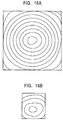
- Hitherto, in pattern matching method, assuming that features of a fingerprint exists mainly in the central portion thereof, template image data has usually been created and stored by extracting image data representing only the central portion of the fingerprint. At the time of identification, an image representing a larger region of a fingerprint which has been read by a fingerprint sensor at the time of identification, shown in Fig. 16A, is compared against the template image representing a smaller region of a fingerprint, shown in Fig. 16B.
- The fingerprint sensor of the type which detects capacitance is relatively expensive. Furthermore, the fingerprint sensor has a large number of cells (elements) for detecting capacitance, and thus is more expensive as the size increases. Accordingly, it is effective to reduce cost of the fingerprint sensor, particularly to use a fingerprint sensor of a smaller size with a smaller number of elements, in order to reduce cost of the fingerprint identification apparatus.
- However, if a fingerprint sensor having a smaller number of elements and therefore having a smaller reading region is used, the region of a fingerprint which is read at the time of identification does not necessarily coincide with the region of a fingerprint which has been stored as a template, inhibiting fingerprint identification, and thus causing the inconvenience that a person who is to input his/her fingerprint is required to let his/her finger be read many times.
- Illustrative embodiments of the present invention seek to provide a fingerprint
identification system, a fingerprint identification apparatus, and a fingerprint identification method in which a fingerprint sensor of a small size is used so as to achieve reduction in cost while maintaining performance of fingerprint identification. - Furthermore, illustrative embodiment of the present invention seek to provide a biometric identification apparatus in which a biometric sensor of a small size is used so as to achieve reduction in cost while maintaining performance of biometric identification.
- To these ends, the present invention, in one aspect thereof, provides a fingerprint identification system including a registration apparatus and an identification apparatus. The registration apparatus includes a first fingerprint sensor for reading a fingerprint in a first region of a human finger to output an image signal representing an image of the fingerprint; a first image data generating unit for generating image data of the fingerprint based on the image signal output from the first fingerprint sensor; and a data output unit for outputting the image data generated by the first image data generating unit. The identification apparatus includes a data input unit for receiving the image data output from the data output unit; a storage unit for storing the image data received by the data input unit; a second fingerprint sensor for reading a fingerprint in a second region of a human finger, which is smaller than the first region, to output an image signal representing an image of the fingerprint; a second image data generating unit for generating image data of the fingerprint based on the image signal output from the second fingerprint sensor; and an image identification unit for comparing the image data generated by the second image data generating unit against the image data stored in the storage unit to determine whether the fingerprints represented by the respective image data coincide with each other.
- According to the fingerprint identification system, when registering a fingerprint, a person who is to register his/her fingerprint places his/her finger on a fingerprint reading unit of the first fingerprint sensor of the registration apparatus. The first fingerprint sensor reads the fingerprint in the first region of the finger to output an image signal representing the fingerprint. The first image data generating unit generates image data of the fingerprint based on the image signal output from the first fingerprint sensor, and the data output unit outputs the image data generated by the first image data generating unit. In the identification apparatus, the data input unit receives the image data output from the data output unit, and the image data is stored in the storage unit.
- When identifying a fingerprint, a person who is to input his/her fingerprint places his/her finger on a fingerprint reading unit of the second fingerprint sensor of the identification apparatus. The second fingerprint sensor reads the fingerprint in the second region of the finger to output an image signal representing the fingerprint. The second image data generating unit generates image data of the fingerprint based on the image signal output from the second fingerprint sensor. The image identification unit compares the image data generated by the second image data generating unit against the image data stored in the storage unit to determine whether the fingerprints represented by the respective image data coincide with each other.
- According to an embodiment of the fingerprint identification system, when registering a fingerprint, the fingerprint is read in a larger region (the first region) by the first fingerprint sensor of the registration apparatus to generate image data; whereas when identifying a fingerprint, the fingerprint is read in a smaller region (the second region) by the second fingerprint sensor of the identification apparatus to generate image data. The image identification unit compares the respective image data to determine whether the fingerprints coincide with each other.
- Thus, even though the reading region for the second fingerprint sensor is smaller and the image data associated with the second fingerprint sensor only represents the fingerprint in the smaller region, the image data associated with the first fingerprint sensor represents the fingerprint in the larger region, so that accurate fingerprint identification is constantly achieved.
- In addition, the second fingerprint sensor has a smaller reading region and thus can be implemented at a lower cost with a smaller number of elements, serving to achieve reduction in cost of an identification apparatus. The cost reduction is extremely advantageous because an identification apparatus is usually owned by each user. Furthermore, since the second fingerprint sensor has a smaller reading region with a smaller number of elements, the fingerprint identification apparatus can be readily incorporated in various portable items, allowing fingerprint identification anytime when required.
- The present invention, in another aspect thereof, provides a fingerprint identification apparatus including a storage unit for storing image data representing an image of a fingerprint in a first region of a human finger; a fingerprint sensor for reading a fingerprint in a second region of a human finger, which is smaller than the first region, to output an image signal representing an image of the fingerprint; an image data generating unit for generating image data of the fingerprint based on the image signal output from the fingerprint sensor; and an image identification unit for comparing the image data generated by the image data generating unit against the image data stored in the storage unit to determine whether the fingerprints represented by the respective image data coincide with each other. Furthermore, an input unit for inputting fingerprint data in the first region to the fingerprint identification apparatus may be provided.
- According to the fingerprint identification apparatus, when identifying a fingerprint, a person who is to input his/her fingerprint places his/her finger on a fingerprint reading unit of the fingerprint sensor of the identification apparatus. The fingerprint sensor reads the fingerprint in the second region of the finger to output an image signal representing the fingerprint. The image data generating unit generates image data of the fingerprint based on the image signal output from the fingerprint sensor. The image identification unit compares the image data generated by the image data generating unit against the image data stored in the storage unit to determine whether the fingerprints represented by the respective image data coincide with each other.
- As described above, according to an embodiment of the fingerprint identification apparatus, when registering a fingerprint, the fingerprint is read in a larger region (the first region) by a fingerprint sensor of a registration apparatus to generate image data; whereas when identifying a fingerprint, the fingerprint is read in a smaller region (the second region) by the fingerprint sensor of the identification apparatus to generate image data. The image identification unit compares the respective image data to determine whether the fingerprints coincide with each other.
- Thus, even though the reading region for the fingerprint sensor of the identification apparatus is smaller and the image data associated with the fingerprint sensor of the identification apparatus only represents the fingerprint in the smaller region, the image data associated with the fingerprint sensor of the registration apparatus represents the fingerprint in the larger region, so that accurate fingerprint identification is constantly achieved.
- In addition, the fingerprint sensor of the identification apparatus has a smaller reading region and thus can be implemented at a lower cost with a smaller number of elements, serving to achieve reduction in cost of an identification apparatus. The coat reduction is extremely advantageous because an identification apparatus is usually owned by each user. Furthermore, since the fingerprint sensor of the identification apparatus has a smaller reading region with a smaller number of elements, the fingerprint identification apparatus can be readily incorporated in various portable items, allowing fingerprint identification anytime when required.
- The present invention, in yet another aspect thereof, provides a fingerprint identification method including a registration apparatus controlling step and an identification apparatus controlling step. The registration apparatus controlling step includes a first image signal output step for reading a fingerprint in a first region of a human finger by a first fingerprint sensor to output an image signal representing an image of the fingerprint; a first image data generating step for generating image data of the fingerprint based on the image signal output in the first image signal output step; and a data output step for outputting the image data generated in the first image data generating step. The identification apparatus controlling step includes a data input step for receiving the image data output in the data output step; a storing step for storing the image data received in the data input step in a storage unit; a second image signal output step for reading a fingerprint in a second region of a human finger, which is smaller than the first region, by a second fingerprint sensor to output an image signal representing an image of the fingerprint; a second image data generating step for generating image data of the fingerprint based on the image signal output in the second image signal output step; and an image identification step for comparing the image data generated in the second image data generating step against the image data stored in the storage unit to determine whether the fingerprints represented by the respective image data coincide with each other.
- According to the fingerprint identification method, when registering a fingerprint, a person who is to register his/her fingerprint places his/her finger on a fingerprint reading unit of the first fingerprint sensor of the registration apparatus. In the first image signal output step, the fingerprint in the first region of the finger is read to output an image signal representing the fingerprint. In the first image data generating step, image data of the fingerprint is generated based on the image signal output in the first image signal output step, and in the data output step, the image data generated in the first image data generating step is output. In the identification apparatus. the image data output in the data output step is received in the data input step, and in the storing step, the image data is stored in the storage unit.
- When identifying a fingerprint, a person who is to input his/her fingerprint places his/her finger on a fingerprint reading unit of the second fingerprint sensor of the identification apparatus. In the second image signal output step, the fingerprint in the second region of the finger is read to output an image signal representing the fingerprint. In the second image data generating step, image data of the fingerprint is generated based on the image signal output in the second image signal output step. In the image identification step, the image data generated in the second image data generating step is compared against the image data stored in the storage unit to determine whether the fingerprints represented by the respective image data coincide with each other.
- As described above, according to an embodiment of the fingerprint identification method, when registering a fingerprint, the fingerprint is read in a larger region (the first region) by the first fingerprint sensor of the registration apparatus to generate image data; whereas when identifying a fingerprint, the fingerprint is read in a smaller region (the second region) by the second fingerprint sensor of the identification apparatus to generate image data. The image identification unit compares the respective image data to determine whether the fingerprints coincide with each other.
- Thus, even though the reading region for the second fingerprint sensor is smaller and the image data associated with the second fingerprint sensor only represents the fingerprint in the smaller region, the image data associated with the first fingerprint sensor represents the fingerprint in the larger region, so that accurate fingerprint identification is constantly achieved.
- In addition, the second fingerprint sensor has a smaller reading region and thus can be implemented at a lower cost with a smaller number of elements, serving to achieve reduction in cost of an identification apparatus. The cost reduction is extremely advantageous because an identification apparatus is usually owned by each user. Furthermore, since the second fingerprint sensor has a smaller reading region with a smaller number of elements, the fingerprint identification apparatus can be readily incorporated in various portable items, allowing fingerprint identification anytime when required.
- The present invention, in another aspect thereof, provides a fingerprint identification method including a storing step for storing in a storage unit image data representing an image of a fingerprint in a first region of a human finger: an image signal output step for reading a fingerprint in a second region of a human finger, which is smaller than the first region, by a fingerprint sensor to output an image signal representing an image of the fingerprint; an image data generating step for generating image data of the fingerprint based on the image signal output in the image signal output step; and an image identification step for comparing the image data generated in the image data generating step against the image data stored in the storage unit to determine whether the fingerprints represented by the respective image data coincide with each other.
- The present invention, in still another aspect thereof, provides a biometric identification apparatus including a storage unit for storing image data representing an image of biometric information in a first region of a human body; a biometric sensor for reading biometric information in a second region of a human body, which is smaller than the first region, to output an image signal representing an image of the biometric information; an image data generating unit for generating image data of the biometric information based on the image signal output from the biometric sensor; and an image identification unit for comparing the image data generated by the image data generating unit against the image data stored in the storage unit to determine whether the biometric information represented by the respective image data coincide with each other. Furthermore, an input unit for inputting biometric information data in the first region to the biometric identification apparatus may be provided.
- According to the biometric identification apparatus, when identifying biometric information, a person who is to input his/her biometric information lets a biometric information reading unit of the biometric sensor of the identification apparatus read the biometric information. The second biometric sensor reads the biometric information in the second region of the person to output an image signal representing the biometric information. The image data generating unit generates image data of the biometric information based on the image signal output from the biometric sensor. The image identification unit compares the image data generated by the image data generating unit against the image data stored in the storage unit to determine whether the biometric information represented by the respective image data coincide with each other.
- As described above, according to an embodiment of the biometric identification apparatus, when registering biometric information, the biometric information is read in a larger region (the first region) by a biometric sensor of a registration apparatus to generate image data; whereas when identifying biometric information, the biometric information is read in a smaller region (the second region) by the biometric sensor of the identification apparatus to generate image data. The image identification unit compares the image data associated with the biometric information which has been read in the smaller region (the second region) against the image data associated with the biometric information which has been read in the larger region (the first region), thereby determining whether the biometric information coincide with each other.
- Thus, even though the reading region for the biometric sensor of the identification apparatus is smaller and the image data associated with the biometric sensor of the identification apparatus only represents the biometric information in the smaller region, the image data associated with the biometric sensor of the registration apparatus represents the biometric information in the larger region, so that accurate biometric identification is constantly achieved.
- In addition, the biometric sensor of the identification apparatus has a smaller reading region and thus can be implemented at a lower cost with a smaller number of elements, serving to achieve reduction in cost of an identification apparatus. The cost reduction is extremely advantageous because an identification apparatus is usually owned by each user. Furthermore, since the biometric sensor of the identification apparatus has a smaller reading region with a smaller number of elements, the biometric identification apparatus can be readily incorporated in various portable items, allowing biometric identification anytime when required.
- The invention will now be described by way of example with reference to the accompanying drawings, throughout which like parts are referred to by like references, and in which:
- Figs. 1A and 1B are block diagrams of a registration apparatus and an identification apparatus constituting a fingerprint identification system according to a first embodiment of the present invention, respectively;
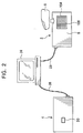
- Fig. 2 is a diagram showing the system configuration for fingerprint registration;
- Fig. 3 is a diagram showing the system configuration for fingerprint identification;
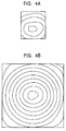
- Figs. 4A and 4B are illustrations showing examples of fingerprint images represented by binary image data generated in the system shown in Figs. 1A and 1B;
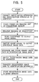
- Fig. 5 is a flowchart of a fingerprint registration operation according to the first embodiment;
- Fig. 6 is a flowchart of a fingerprint identification operation according to the first embodiment;
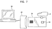
- Fig. 7 is a diagram showing the configuration of an example of a smart card (IC card) system using a smart card (IC card) incorporating a fingerprint sensor:
- Fig. 8 is a flowchart of a fingerprint identification operation according to a second embodiment;
- Fig. 9 is an illustration of images represented by binary image data stored in an image memory;
- Fig. 10 is a block diagram showing the construction of an identification apparatus according to a third embodiment;
- Figs. 11A is an external view of the identification apparatus according to the third embodiment, and Fig. 11B is an external view thereof with a fingerprint sensor exposed;
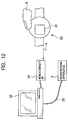
- Fig. 12 is an illustration showing the configuration of a fingerprint identification system according to the third embodiment;
- Fig. 13 is a flowchart of a fingerprint registration operation according to the third embodiment;
- Fig. 14 is a flowchart of a fingerprint identification operation according to the third embodiment;
- Fig. 15 is an external view of an example of conventional fingerprint identification apparatus; and
- Figs. 16A and 16B are illustrations showing examples of fingerprint images represented by binary image data generated in the conventional fingerprint identification apparatus.
-
- Preferred embodiments of fingerprint identification system, fingerprint identification method and identification apparatus, and biometric identifioation apparatus will now be described with reference to the accompanying drawings.
- Figs. 1A and 1B are block diagrams of a registration apparatus and an identification apparatus constituting a fingerprint identification system according to a first embodiment of the present invention, respectively. Fig. 2 is a diagram showing the system configuration for fingerprint registration, and Fig. 3 is a diagram showing the system configuration for fingerprint identification.
- The fingerprint identification system according to the first embodiment includes a
registration apparatus 2 and anidentification apparatus 4 shown in Figs. 1A and 1B. - The
registration apparatus 2 has afingerprint sensor 104 disposed on a surface of acase 6, as shown in Fig. 2. Thefingerprint sensor 104 is implemented by a semiconductor sensor which detects variation in capacitance due to ridges and valleys of a fingerprint when a finger 8 is placed on afingerprint reading unit 108 and which outputs an electric image signal representing the fingerprint. Thefingerprint sensor 104 reads a fingerprint in a region (a first region) which is large enough to cover substantially the entire fingerprint of a finger at once, as in the case with the related art. - More specifically, as shown in Fig. 1A. the
registration apparatus 2 further includes an A/D converter 12, afingerprint registration circuit 14, animage memory 16, a CPU (central processing unit) 18, and aprogram memory 20. - The A/
D converter 12 digitizes the image signal of the fingerprint output by thefingerprint sensor 104, and outputs image data representing a grayscale image of the fingerprint. - The
fingerprint registration circuit 14 is implemented, for example, by an LSI. Thefingerprint registration circuit 14 generates, based on the image data from the A/D converter 12, binary image data which serves as registration image data representing a binary image of the fingerprint, and stores the registration image data in theimage memory 16 which is implemented, for example, by a rewritable, nonvolatile memory, via abus line 22. - The A/
D converter 12 and thefingerprint registration circuit 14 constitute first image data generating means according to the present invention. - The
program memory 20 includes a RAM (random access memory) and a ROM (read-only memory). TheCPU 18 fetches a program stored in the ROM via thebus line 22, and operates according to the program using the RAM as required, thereby exercising overall control on theregistration apparatus 2. - A USB (Universal Serial Bus)
controller 26 is connected to thebus line 22, and it functions as an interface for connecting theregistration apparatus 2 to a computer 24 (shown in Fig. 2) via aUSB cable 28. Thecomputer 24 may be, for example, a personal computer. - The
CPU 18, together with theUSB controller 26, constitutes data output means according to the present invention, and it outputs the registration image data stored in theimage memory 16 to thecomputer 24 via thebus line 22, theUSB controller 26, and theUSB cable 28. - The
identification apparatus 4 is constructed similarly to theregistration apparatus 2, but thefingerprint sensor 104 and thefingerprint registration circuit 14 are replaced with afingerprint sensor 30 and afingerprint identification circuit 32. In Fig. 1B, parts that are identical to those in Fig. 1A are designated by the same numbers, and descriptions thereof will be omitted. - The
fingerprint sensor 30 is implemented by a semiconductor sensor which detects variation in capacitance due to ridges and valleys of a fingerprint and which outputs an electric image signal representing the fingerprint, similarly to thefingerprint sensor 104; however, thefingerprint sensor 30 reads a fingerprint in a region (a second region) which is smaller than the reading region for thefingerprint sensor 104, for example, on the order of a quarter. Thus, thefingerprint sensor 30 usually reads only a portion of a fingerprint. - Furthermore, in the
identification apparatus 4, thefingerprint identification circuit 32, which is provided in place of thefingerprint registration circuit 14, is implemented, for example, by an LSI. Thefingerprint identification circuit 32, together with the A/D converter 12, constitutes second image data generating means according to the present invention, and it also constitutes image identification means. More specifically, thefingerprint identification circuit 32 generates, based on the image data from the A/D converter 12, binary image data which serves as input image data representing a binary image of the fingerprint. Furthermore, thefingerprint identification circuit 32 compares, by pattern matching, the input image data against the registration image data of a fingerprint which is received from theregistration apparatus 2 and stored in theimage memory 16 in advance, thereby determining whether the fingerprints represented by the respective binary image data coincide with each other. - In the
identification apparatus 4, theCPU 18 constitutes data input means together with theUSB controller 26, and it receives the registration image data of a fingerprint from theregistration apparatus 2 via theUSB cable 28, and stores the registration image data in the image memory 16 (storage means according to the present invention). - In this embodiment, a fingerprint is used as biometric information representing a biometric feature of an individual user. Furthermore, the
fingerprint sensor 104 constitutes a first biometric sensor according to the present invention and thefingerprint sensor 30 constitutes a second biometric sensor according to the present invention. - Next, an operation for registering a fingerprint in the fingerprint identification system constructed as described above will be described with reference to a flowchart shown in Fig. 5.
- When registering a fingerprint, the
registration apparatus 2 and theidentification apparatus 4 are connected to thecomputer 24 via the USB cable 28 (step S10), as shown in Fig. 2. - Then, a person who is to register his/her fingerprint places his/her finger on the
reading unit 108 of thefingerprint sensor 104 in the registration apparatus 2 (step S12). An operator of thecomputer 24 performs a predetermined operation on thecomputer 24, requesting theregistration apparatus 2 to read the fingerprint (step S14). - Thus, the
fingerprint sensor 104 reads the fingerprint of substantially the entire finger placed on thereading unit 108, and outputs an image signal the fingerprint (step S16). The A/D converter 12 (shown in Fig. 1A) dagttizes the image signal to output a grayscale image data (step S18). - The
fingerprint registration circuit 14 binarizes the grayscale image data received from the A/D converter 12, thus generating binary image data which serves as registration image data of the fingerprint, and it stores the registration image data in the image memory 16 (step S20). The image represented by the registration image data stored in theimage memory 16 is, for example, as shown in Fig. 4B. - Then, the
CPU 18 reads the registration image data of the fingerprint from theimage memory 16, and outputs the registration image data to thecomputer 24 via theUSB controller 26 and the USB cable 28 (step S22). Thecomputer 24 transfers the registration image data to theidentification apparatus 4 via the USB cable 28 (step S24). - The
CPU 18 of the identification apparatus 4 (shown in Fig. 1B) receives the registration image data via theUSB cable 28 and theUSB controller 26, and stores the registration image data in the image memory 16 (step S26). - Next, an operation for identifying a fingerprint will be described with reference to a flowchart shown in Fig. 6.
- When identifying a fingerprint, the
identification apparatus 4 is connected to thecomputer 24 via the USB cable 28 (step S30), as shown in Fig. 3. - Then, a person who is to input his/her fingerprint places his/her finger on a
reading unit 301 of the fingerprint sensor 30 (step S32). An operator of thecomputer 24 performs a predetermined operation on thecomputer 24, requesting theidentification apparatus 4 to read the fingerprint via the computer 24 (step 34). - Thus, the
fingerprint sensor 30 reads the fingerprint of a part of the finger placed on thereading unit 301, outputting an image signal representing the fingerprint (step S36). The A/D converter digitizes the image signal to output grayscale image data (step S38). - The
fingerprint identification circuit 32 binarizes the grayscale image data received from the A/D converter 21, thus generating binary image data which serves as input image data of the fingerprint (step S40). The image represented by the input image data generated by thefingerprint identification circuit 32 based on the data form the A/D converter 12 shows only a part of the fingerprint, as shown in Fig. 4A. - The
fingerprint identification circuit 32 reads the registration image data stored in advance in theimage memory 16 as described earlier (step S42), and compares, by pattern matching, the input image data which has been newly generated based on the data from the A/D converter 12 against the registration image data which has been read. thereby determining whether the fingerprints represented by the respective image data coincide with each other on the basis of a particular criterion (step S44). - The input image data represents only a part of the fingerprint as described earlier (shown in Fig. 4A), whereas the registration image data stored in the
image memory 16 represents substantially the entire fingerprint (shown in Fig. 4B); accordingly, thefingerprint identification circuit 32 performs pattern matching while moving the position of the image represented by the input image data over the entire image represented by the registration image data. - The
CPU 18 of theidentification apparatus 4 is notified of the identification result via thebus line 22, and theCPU 18 notifies thecomputer 24 of the identification result via theUSB controller 26 and the USB cable 28 (step S46). - As described above, according to this embodiment, the
fingerprint sensor 30 of theidentification apparatus 4 covers a smaller region and thus input image data to be identified is acquired only from the smaller region; whereas thefingerprint sensor 104 of theregistration apparatus 2 covers a larger region so that registration image data is acquired from the larger region. - Thus, even if input image data to be identified is acquired only from the smaller region and if the data misses the central portion of the fingerprint, the
fingerprint identification circuit 32 constantly compares the respective image data with accuracy, successfully determining whether the fingerprints represented by the respective image data coincide with each other. - Furthermore, since the
fingerprint sensor 30 reads a fingerprint in the smaller region, thefingerprint sensor 30 can be implemented at a lower cost with a smaller number of elements, serving to reduce cost of theidentification apparatus 4. Since theidentification apparatus 4 is owned by each user, reduction in cost thereof is extremely advantageous. - More specifically, cost of the
registration apparatus 2 remains the same as in the related art since a fingerprint sensor with a larger reading region is used, and cost of the system as a whole increases because theregistration apparatus 2 and theidentification apparatus 4 are separately provided. However, since each user is not required to own theregistration apparatus 2 individually and is required only to own theidentification apparatus 4, reduction in cost of theidentification apparatus 4 is extremely advantageous. - Furthermore, the
small fingerprint sensor 30 can be suitably incorporated in portable electronic apparatuses such as cellular phones. Thus, for example, a cellular phone with a fingerprint identification function, which serves as theidentification apparatus 4, can be readily implemented. - Furthermore, owing to the smaller size of the
fingerprint sensor 30, theidentification apparatus 4 can be readily implemented in the form of a smart card (IC card) (an example of portable item in Claims) with a fingerprint sensor for identification. Fig. 7 is a diagram showing the configuration of an example of a smart card (IC card) system in which a smart card (IC card) incorporating such a fingerprint sensor is used. In the system, as shown in Fig. 7, a smart card (IC card) 34 incorporates afingerprint sensor 36 which is equivalent to thefingerprint sensor 30. Thefingerprint sensor 36 reads a fingerprint in order to authenticate the user of a card. Only if the user is found to be a legitimate user, acomputer 38 is allowed to exchange data with thesmart card 34 via acard reader 40. As opposed to currently used smart cards (IC cards) which allow personal authentication only by use of a password, the fingerprint identification system according to this embodiment serves to implement a highly secure smart card (IC card) system. - Furthermore, smart cards (IC cards) easily bend, and a large fingerprint sensor is more likely to be affected by bending and thus damaged. In contrast, the present invention is advantageous in that a fingerprint sensor of a smaller size is used.
- The
registration apparatus 2 is typically prepared by the issuer of thesmart card 34, and provided, for example, at a registration center together with a card reader which is also capable of writing, so that when thesmart card 34 is issued, the fingerprint of the user of thesmart card 34 is read by theregistration apparatus 2 and registered via the card reader in thesmart card 34 which serves as theregistration apparatus 4. - These techniques can be applied to smart cards (IC cards) for various applications, such as driving licenses, passports, credit cards, etc.
- Furthermore, obviously, application of the present invention is not limited to smart cards (IC cards). For example, since an identification apparatus can be readily implemented in a small size, a key to home or office, a key of a car, etc. may be implemented as an identification apparatus according to the present invention. In that case, the key can be implemented with a wireless interface, and only a legitimate user of the key is allowed to use the key based on fingerprint identification.
- Although the binary image data generated by the
registration apparatus 2 is directly output to theidentification apparatus 4 via thecomputer 24 in this embodiment, advantageously, the binary image data may be encrypted before being output to thecomputer 24, which serves to avoid security concerns associated with thecomputer 24 on route. The encryption may be performed based on, for example, a public key encryption method. - Furthermore, when the binary image data from the
registration apparatus 2 is stored in theimage memory 16 in theidentification apparatus 4, advantageously, the binary image data may be encrypted before being stored in theimage memory 16, which further enhances security. - The binary image data generated by the
registration apparatus 2 need not necessarily be stored in theimage memory 16 of theidentification apparatus 4 in advance. Alternatively, the binary image data generated by theregistration apparatus 2 may be stored in a server connected to a communication network or in a computer, and transferred to theregistration apparatus 2 via the network or from the computer and stored in theimage memory 16 at the time of fingerprint identification. - Furthermore, although the binary image data of a fingerprint registered in the
registration apparatus 2 is transferred to theidentification apparatus 4 via thecomputer 24 in this embodiment, theregistration apparatus 2 and theidentification apparatus 4 may be connected without a computer, a network, etc. in the middle so that the binary image data will be transferred directly. In this case, fingerprint information is not passed to any system other than theregistration apparatus 2 and theidentification apparatus 4. Thus, the fingerprint information is prevented from being stolen or interpolated, which serves to achieve improved security. - Although the
registration apparatus 2 is used only for registration of a fingerprint in this embodiment, advantageously, theregistration apparatus 2 may also have a fingerprint identification function so that a fingerprint can also be identified based on data acquired by thefingerprint sensor 104. - Furthermore, although the
registration apparatus 2 and theidentification apparatus 4 are connected by USB, for example, to a computer, theregistration apparatus 2 and theidentification apparatus 4 may also be connected to a computer, etc. based on, for example, RS232C standard. - Next, a second embodiment will be described.
- The second embodiment differs from the first embodiment in that when identifying a fingerprint, the
fingerprint sensor 104 reads a fingerprint a plurality of times to acquire a plurality of input image data, so that the plurality of input image data are compared against registration image data. - Accordingly, the
image memory 16 of theidentification apparatus 4 is constructed so that a plurality of input image data can be stored in addition to registration image data. - Fig. 8 is a flowchart of an operation for identifying a fingerprint according to the second embodiment.
- When identifying a fingerprint, the
identification apparatus 4 is connected to thecomputer 24 via the USB cable 28 (step S130), as shown in Fig. 3. - Then, a person who is to input his/her fingerprint places his/her finger on the
reading unit 301 of the fingerprint sensor 30 (step S132). An operator of thecomputer 24 performs a predetermined operation on thecomputer 24, requesting theidentification apparatus 4 to read the fingerprint (step S134). - Thus, the
fingerprint sensor 30 reads the fingerprint of a part of the finger placed on thereading unit 301, outputting an image signal representing the fingerprint (step S136). The A/D converter 12 digitizes the image signal to output gray-scale image data (step S138). - The
fingerprint identification circuit 32 binarizes the grayscale image data received from the A/D converter 12, thus generating binary image data which serves as input image data representing the fingerprint, and stores the input image data in the image memory 16 (step S140). The image represented by the input image data shows only a portion of the fingerprint, as shown in Fig. 4A, similarly to the first embodiment. - The
CPU 18 determines whether the number of input image data stored in theimage memory 16 has reached a predetermined number (e.g., three times in this embodiment), i.e., whether the predetermined number of input image data has been acquired (step S142). - If step S142 evaluates to "N", the
CPU 18 transmits to thecomputer 24 information for prompting the user to place his/her finger again on thefingerprint sensor 30, whereby thecomputer 24 prompts the user to place his/her finger again, for example, by displaying a message (step S144). Then, the process returns to step S132. the same steps are repeated. - On the other hand, if step S142 evaluates to "Y", the
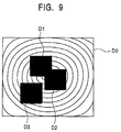
fingerprint identification circuit 32 reads the registration image data which has been stored in advance in theimage memory 16 and the plurality of input image data, and performs identification by pattern matching (step S146). - Fig. 9 is an illustration showing images represented by the registration image data and the plurality of input image data stored in the
image memory 16. - As shown in Fig. 9, with respect to the image represented by the registration image data D0, the images represented respectively by the plurality (three in this embodiment) of input image data D1, D2, and D3 are located at different positions. This is because the position of the finger with respect to the
fingerprint sensor 30 varies each time the finger is placed for the fingerprint to be read. - Then, scores of coincidence indicating the results of pattern matching between the registration image data and each of the input image data are calculated (step S148), and it is determined whether the total score exceeds a predetermined threshold value (step S150).
- The threshold value is set to a value such that it is accurately determined that input image data matches registration image data when the total score exceeds the threshold value.
- If step S150 evaluates to "Y", identification ends in success. If step S150 evaluates to "N", identification ends in failure.
- The second embodiment achieves the same operation and advantages as the first embodiment, and in addition, is advantageous in improving accuracy of fingerprint identification because a plurality of input image data is compared against registration image data.
- In the second embodiment, scores indicating coincidence between the registration image data and each of the input image data are calculated, and it is determined whether the input image data coincides with the registration image data based on whether the total score exceeds a predetermined threshold value. Alternatively, whether the input image data coincides with the registration image data may be determined by comparing each of the scores with a predetermined threshold value and based on whether the individual scores exceed the threshold value more often than a predetermined number of times.
- Next, a third embodiment will be described.
- In the third embodiment, an identification apparatus is implemented in the form of a wristwatch.
- Fig. 10 is a block diagram showing the construction of an identification apparatus according to the third embodiment. Fig. 11A is an external view of the identification apparatus, and Fig. 11B is an external view thereof in which a fingerprint sensor is exposed. Fig. 12 is a diagram showing the configuration of a fingerprint identification system according to the third embodiment. Parts that are identical to those in the first embodiment are designated by the same numbers.
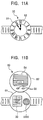
- As shown in Figs. 11A and 11B, an
identification apparatus 50 is implemented in the form of a wristwatch (an example of portable item in Claims). Theidentification apparatus 50 includes amain unit 51, and atimepiece unit 52 which can be opened and closed by a hinge with respect to the top surface of themain unit 51. - When the
timepiece unit 52 is closed with respect to themain unit 51, the top surface of themain unit 51 is covered by the bottom surface of thetimepiece unit 52 and thetimepiece unit 52 faces outward; whereas when thetimepiece unit 52 is opened with respect to themain unit 51, the top surface of themain unit 51 faces outward. - On the top surface of the
main unit 51, afingerprint sensor 30 and a microphone/speaker 5302 are provided. On the bottom surface of thetimepiece unit 52, adisplay unit 54 implemented by an LCD and anoperation unit 55 having operation buttons are provided. - As shown in Fig. 10, the
identification apparatus 50 includes an A/D converter 12, animage memory 16, aCPU 18, aprogram memory 20, thefingerprint sensor 30, and afingerprint identification circuit 32, which are similar to the first embodiment and whose descriptions will be omitted. - The
identification apparatus 50, in addition to the above construction, includes thetimepiece unit 52, thedisplay unit 54, theoperation unit 55, and furthermore, aphone unit 53 and anon-contact interface 56. - The
timepiece unit 52 shows time. Thedisplay unit 54 is controlled by theCPU 18 so as to display characters, symbols, etc. - The
phone unit 53 includes the microphone/speaker 5302. and has functionality equivalent to that of a cellular phone. - The
operation unit 55 is used to perform operations required in operation of the identification apparatus S0. - The
non-contact interface 56 serves to exchange information using, for example, infrared signals or radio signals, bilaterally with anon-contact interface 62 provided in acomputer 60 which is equivalent to thecomputer 24 in the first embodiment. - In this embodiment, the
CPU 18 operates based on programs stored in theprogram memory 20 so that thedisplay unit 54, theoperation unit 55, a memory which is not shown, etc. cooperate to function, for example, as an electronic notebook or a PDA. - Next, the operation of a fingerprint identification system using the
identification apparatus 50 will be described with reference to a flowchart shown in Fig. 13. - When registering a fingerprint, the
registration apparatus 2 is connected to thecomputer 60 via theUSB cable 28, and theidentification apparatus 50 is allowed to communicate with thecomputer 60 via thenon-contact interface 56 and the non-contact interface 62 (step S210), as shown in Fig. 12. - Then, in the
registration apparatus 2, a person who is to register his/her fingerprint places his/her finger on thereading unit 108 of the fingerprint sensor 104 (step S212). An operator of thecomputer 60 performs a predetermined operation on thecomputer 60, requesting theregistration apparatus 2 to read the fingerprint (step S214). - Thus, the
fingerprint sensor 104 reads the fingerprint of substantially the entire finger placed on thereading unit 108, and outputs an image signal representing the fingerprint (step S216). The A/D converter 12 (shown in Fig. 1A) digitizes the image signal to output grayscale image data (step S218). - The
fingerprint registration circuit 14 binarizes the grayscale image data received from the A/D converter 12, thus generating binary image data which serves as registration image data of the fingerprint, and stores the registration image data in the image memory 16 (step S220). The image represented by the registration image data stored in theimage memory 16 is, for example, as shown in Fig. 4B. - Then, the
CPU 18 reads the registration image data of the fingerprint from theimage memory 16 and outputs the registration image data to thecomputer 60 via theUSB controller 26 and the USB cable 28 (step S222). Thecomputer 60 transfers the registration image data to theidentification apparatus 50 via thenon-contact interface 62 and the non-contact interface 56 (step S224). - The
CPU 18 of theidentification apparatus 50 receives the registration image data via thenon-contact interface 62 and thenon-contact interface 56 and stores the registration image data in the image memory 16 (step S226). - Next, an operation for identifying a fingerprint will be described with reference to a flowchart shown in Fig. 14.
- When identifying a fingerprint, the
identification apparatus 50 is allowed to communicate with thecomputer 60 via thenon-contact interface 56 and the non-contact interface 62 (step S230), as shown in Fig. 3. - Then, a person who is to input his/her fingerprint places his/her finger on the
reading unit 301 of the fingerprint sensor 30 (step S232). An operator of thecomputer 60 performs a predetermined operation on thecomputer 60, requesting theidentification apparatus 4 to read the fingerprint (step S234). - Thus, the
fingerprint sensor 30 reads the fingerprint of a portion of the finger placed on thereading unit 301, outputting an image signal representing the fingerprint (step S236). The A/D converter 12 digitizes the image signal to output grayscale image data (step S238). - The
fingerprint identification circuit 32 binarizes the grayscale image data received from the A/D converter 12, thus generating binary image data which serves as input image data of the fingerprint (step S240). The image represented by the input image data generated by thefingerprint identification circuit 32 based on the data from the A/D converter 12 showe only a portion of the fingerprint, as shown in Fig. 4A. - The
fingerprint identification circuit 32 reads the registration image data which has been stored in theimage memory 16 as described earlier (step S242). Thefingerprint identification circuit 32 then compares, by pattern matching, the input image data which has been newly generated based on the data from the A/D converter 12 against the registration image data which has been read, thereby determining whether the fingerprints represented by the respective image data coincide with each other on the basis of a predetermined criterion (step S244). - The input image data represents only a portion of the fingerprint as described earlier (shown in Fig. 4A), whereas the registration image data stored in the
image memory 16 represents substantially the entire fingerprint (shown in Fig. 4B); thus, thefingerprint identification circuit 32 performs pattern matching while moving the position of the image represented by the input image data over the entire image represented by the registration image data. - The
CPU 18 is notified of the identification result via thebus line 22, and theCPU 18 notifies thecomputer 60 of the identification result via thenon-contact interface 56 and the non-contact interface 60 (step S246). - According to the third embodiment described above. the same operation and advantages are achieved. In addition, the identification apparatus is implemented in the form of a wristwatch, which can be constantly carried; thus, the identification apparatus is small in size and portable, readily allowing fingerprint identification anytime and anywhere. This serves to improve convenience of personal authentication. Furthermore, the reduced size of the identification apparatus advantageously serves to reduce cost.
- Furthermore, comparison of the input image data against the registration image data may be performed in a manner similar to the second embodiment.
- Furthermore, similarly to the first embodiment, the registration image data generated by the
registration apparatus 2 may be encrypted before being output to thecomputer 60, and in theidentification apparatus 50, the registration image data may be encrypted before being stored in theimage memory 16, which serves to enhance security. - Furthermore, although the
computer 60 is used as an apparatus for forwarding the result of identification by theidentification apparatus 50 in the third embodiment, the present invention may be applied to various cases where fingerprint identification is required, including the following examples: - 1) In a locking system for locking a door to home, the
door is unlocked based on the result of fingerprint
identification by the
identification apparatus 50. - 2) In a television broadcast which allows bilateral
communications or in a system for stock trading over the
Internet, confirmation of stock trades is performed based on
the result of fingerprint identification by the
identification apparatus 50. - 3) In a system for controlling a private car, the door
is unlocked and the engine is started based on the result of
fingerprint identification by the
identification apparatus 50. - 4) When accessing an office LAN from a terminal
apparatus such as a notebook computer, access to the LAN is
permitted based on the result of fingerprint identification
by the
identification apparatus 50. - 5) In an office time recorder, arrival time is
recorded based on the result of fingerprint identification
by the
identification apparatus 50. - 6) When activating an office computer, activation of
the computer is permitted based on the result of fingerprint
identification by the
identification apparatus 50. - 7) In a system for filing or approving documents,
documents are filed or approved based on the result of
fingerprint identification by the
identification apparatus 50. - 8) When shopping on a credit card, transaction is
settled based on the result of fingerprint identification by
the
identification apparatus 50. - 9) In a system for reserving tickets for entertainment
events such as concerts, reservation is made based on the
result of fingerprint identification by the
identification apparatus 50. -
- Furthermore, an identification apparatus according to the present invention may be incorporated in a telephone card, a credit card, a cash card, a card to be used in ATM of a bank, a ticket or commutation ticket for various public transportation services, a passport, a driving license, an insurance card, etc. as well as in a smart card (IC card) and a wristwatch as described earlier.
- In the embodiments described above, the registration apparatus and the identification apparatus are connected to a computer via USB cables; however, alternatively, the connection may be formed using other types of wires or by wireless, with any type of suitable interfaces.
- Furthermore, although image data is transferred from the registration apparatus to the identification apparatus via a computer, the registration apparatus and the identification apparatus may be directly connected without a computer in the middle so that image data will be directly transferred.
- The fingerprint sensor is not limited to the type which detects capacitance, and may be, for example, an optical type using CCD. When an optical fingerprint sensor is used, an identification apparatus can be readily incorporated in various portable items mentioned earlier by reducing the size of the optical system so that fingerprint identification is allowed whenever required, similarly to the embodiments described above in which the size of the fingerprint sensor in the identification apparatus is reduced. Furthermore, cost can be reduced by using a CMOS sensor with a smaller number of elements as the fingerprint sensor of the identification apparatus.
- In the embodiments described above, fingerprint is used as information relating to biometric features of an individual user, i.e., biometric information which can be read from the body of the user; however, as an alternative to fingerprint, for example, retina or iris may be used as biometric information.
- When retina is used, a pattern of blood vessels which appear on retina at the back of an eye is read. Iris is thin-film tissue for coordinating contraction and expansion of pupil of an eye, whose pattern is unique to each individual. The pattern becomes stable in two years after birth, and then remains unchanged over one's lifetime. Furthermore, iris is so complex that it differs among people who share the same relevant genes.
- A biometric sensor for reading biometric information can be implemented by a known type. For example, as a biometric sensor for reading retina, the type which irradiates retina with light from outside, such as a fundus photography apparatus, can be used.
- When biometric information is used as described above, a biometric identification apparatus can be implemented similarly to the embodiments described above, achieving the same operation and advantages.
- In so far as the embodiments of the invention described above are implemented, at least in part, using software-controlled data processing apparatus, it will be appreciated that a computer program providing such software control and a transmission, storage or other medium by which such a computer program is provided are envisaged as aspects of the present invention.
Claims (21)
- A fingerprint identification system comprising a registration apparatus and an identification apparatus,
said registration apparatus comprising:a first fingerprint sensor for reading a fingerprint in a first region of a human finger to output an image signal representing an image of the fingerprint;first image data generating means for generating image data of the fingerprint based on the image signal output from said first fingerprint sensor; anddata output means for outputting the image data generated by said first image data generating means;said Identification apparatus comprising:data input means for receiving the image data output from said data output means;storage means for storing the image data received by said data input means;a second fingerprint sensor for reading a fingerprint in a second region of a human finger, which is smaller than said first region, to output an image signal representing an image of the fingerprint;second image data generating means for generating image data of the fingerprint based on the image signal output from said second fingerprint sensor; andimage identification means for comparing the image data generated by said second image data generating means against the image data stored in said storage means to determine whether the fingerprints represented by the respective image data coincide with each other. - A fingerprint identification apparatus comprising:storage means for storing image data representing an image of a fingerprint in a first region of a human finger;a fingerprint sensor for reading a fingerprint in a second region of a human finger, which is smaller than said first region, to output an image signal representing an image of the fingerprint;image data generating means for generating image data of the fingerprint based on the image signal output from said fingerprint sensor; andimage identification means for comparing the image data generated by said image data generating means against the image data stored in said storage means to determine whether the fingerprints represented by the respective image data coincide with each other.
- A fingerprint identification apparatus according to Claim 2, wherein said fingerprint sensor generates the image signal by detecting variation in capacitance due to ridges and valleys of the fingerprint when the finger is placed on a fingerprint reading unit.
- A fingerprint identification apparatus according to Claim 2, wherein said image data generating means generates image data representing a binary image of the fingerprint based on the image signal output from said fingerprint sensor.
- A fingerprint identification apparatus according to Claim 2, wherein said image identification means compares the image data generated by said image data generating means against the image data stored in said storage means by pattern matching to determine whether the fingerprints represented by the respective image data coincide with each other.
- A fingerprint identification apparatus according to Claim 2, wherein said fingerprint sensor reads the fingerprint a plurality of times with the finger placed at different positions with respect to said fingerprint sensor so that said image data generating means generates a plurality of image data of the fingerprint, and said image identification means compares each of the plurality of image data generated by said image data generating means against the image data stored in said storage means to calculate scores each indicating the degree of coincidence between the respective image data, thereby determining whether the fingerprints represented by the respective image data coincide with each other based on the scores.
- A fingerprint identification apparatus according to Claim 6, wherein said image identification means determines coincidence based on a comparison of the total of the scores with a predetermined threshold value.
- A fingerprint identification apparatus according to Claim 6, wherein said image identification means determines coincidence based on individual comparisons of each of the scores with a predetermined threshold value.
- A fingerprint identification apparatus according to Claim 2, wherein said fingerprint identification apparatus is incorporated in a portable item.
- A fingerprint identification apparatus according to Claim 9, wherein said portable item comprises a wristwatch or a smart card (IC card).
- A fingerprint identification method comprising a registration apparatus controlling step and an identification apparatus controlling step,
said registration apparatus controlling step comprising:a first image signal output step for reading a fingerprint in a first region of a human finger by a first fingerprint sensor to output an image signal representing an image of the fingerprint;a first image data generating step for generating image data of the fingerprint based on the image signal output in said first image signal output step; anda data output step for outputting the image data generated in said first image data generating step;said identification apparatus controlling step comprising:a data input step for receiving the image data output in said data output step;a storing step for storing the image data received in said data input step in storage means;a second image signal output step for reading a fingerprint in a second region of a human finger, which is smaller than said first region, by a second fingerprint sensor to output an image signal representing an image of the fingerprint;a second image data generating step for generating image data of the fingerprint based on the image signal output in said second image signal output step; andan image identification step for comparing the image data generated in said second image data generating step against the image data stored in said storage means to determine whether the fingerprints represented by the respective image data coincide with each other. - A fingerprint identification method comprising:a storing step for storing in storage means image data representing an image of a fingerprint in a first region of a human finger;an image signal output step for reading a fingerprint in a second region of a human finger, which is smaller than said first region, by a fingerprint sensor to output an image signal representing an image of the fingerprint;an image data generating step for generating image data of the fingerprint based on the image signal output in said image signal output step; andan image identification step for comparing the image data generated in said image data generating step against the image data stored in said storage means to determine whether the fingerprints represented by the respective image data coincide with each other.
- A fingerprint identification method according to Claim 12, wherein the fingerprint is read in said image signal output step a plurality of times with the finger placed at different positions with respect to said fingerprint sensor so that a plurality of image data of the fingerprint is generated in said image data generating step, and in said image identification step, each of the plurality of image data generated in said image data generating step is compared against the image data stored in said storage means to calculate scores each indicating the degree of coincidence between the respective image data, thereby determining whether the fingerprints represented by the respective image data coincide with each other based on the soores.
- A biometric identification apparatus comprising:storage means for storing image data representing an image of biometric information in a first region of a human body;a biometric sensor for reading biometric information in a second region of a human body, which is smaller than said first region, to output an image signal representing an image of the biometric information;image data generating means for generating image data of the biometric information based on the image signal output from said biometric sensor; andimage identification means for comparing the image data generated by said image data generating means against the image data stored in said storage means to determine whether the biometric information represented by the respective image data coincide with each other.
- A biometric identification apparatus according to Claim 14, wherein said image data generating means generates image data representing a binary image of the biometric information based on the image signal output from said biometric sensor.
- A biometric identification apparatus according to Claim 14, wherein said image identification means compares the image data generated by said image data generating means against the image data stored in said storage means by pattern matching to determine whether the biometric information represented by the respective image data coincide with each other.
- A biometric identification apparatus according to Claim 14, wherein said biometric sensor reads the biometric information a plurality of times with the relevant part of the human body placed at different positions with respect to said biometric sensor so that said image data generating means generates a plurality of image data of the biometric information, and said image identification means compares each of the plurality of image data generated by said image data generating means against the image data stored in said storage means to calculate scores each indicating the degree of coincidence between the respective image data, thereby determining whether the biometric information represented by the respective image data coincide with each other based on the scores.
- A biometric identification apparatus according to Claim 17, wherein said image identification means determines coincidence based on a comparison of the total of the scores with a predetermined threshold value.
- A biometric identification apparatus according to Claim 17, wherein said image identification means determines coincidence based on individual comparisons of each of the scores with a predetermined threshold value.
- A biometric identification apparatus according to Claim 14, wherein said biometric identification apparatus is incorporated in a portable item.
- A biometric identification apparatus according to Claim 20, wherein said portable item comprises a wristwatch or a smart card (IC card).
Applications Claiming Priority (4)
| Application Number | Priority Date | Filing Date | Title |
|---|---|---|---|
| JP2001062859 | 2001-03-07 | ||
| JP2001062859 | 2001-03-07 | ||
| JP2001345719 | 2001-11-12 | ||
| JP2001345719A JP4164732B2 (en) | 2001-03-07 | 2001-11-12 | Fingerprint verification system, fingerprint verification device, fingerprint verification method, and biometric verification device |
Publications (3)
| Publication Number | Publication Date |
|---|---|
| EP1239404A2 true EP1239404A2 (en) | 2002-09-11 |
| EP1239404A3 EP1239404A3 (en) | 2005-08-17 |
| EP1239404B1 EP1239404B1 (en) | 2007-10-31 |
Family
ID=26610740
Family Applications (1)
| Application Number | Title | Priority Date | Filing Date |
|---|---|---|---|
| EP02251564A Expired - Fee Related EP1239404B1 (en) | 2001-03-07 | 2002-03-06 | Fingerprint identification system fingerprint identification apparatus, fingerprint identification method, and biometric identification apparatus |
Country Status (4)
| Country | Link |
|---|---|
| US (1) | US6980673B2 (en) |
| EP (1) | EP1239404B1 (en) |
| JP (1) | JP4164732B2 (en) |
| DE (1) | DE60223189T2 (en) |
Cited By (12)
| Publication number | Priority date | Publication date | Assignee | Title |
|---|---|---|---|---|
| EP1353291A3 (en) * | 2002-04-10 | 2005-05-04 | NEC Corporation | Fingerprint authenticating system using a small fingerprint sensor |
| US6980673B2 (en) * | 2001-03-07 | 2005-12-27 | Sony Corporation | Fingerprint identification system, fingerprint identification apparatus, fingerprint identification method, and biometric identification apparatus |
| EP1619622A1 (en) * | 2003-04-25 | 2006-01-25 | Fujitsu Limited | Fingerprint matching device, fingerprint matching method, and fingerprint matching program |
| EP1754178A2 (en) * | 2004-01-07 | 2007-02-21 | Identification International, Inc. | Low power fingerprint capture system, apparatus, and method |
| US20100085153A1 (en) * | 2008-09-05 | 2010-04-08 | Smith Gaylan S | Biometric Control System and Method For Machinery |
| EP2105865A3 (en) * | 2008-03-25 | 2010-05-26 | Fujitsu Limited | Biometric authentication apparatus and biometric data registration apparatus |
| US7812936B2 (en) | 2007-04-09 | 2010-10-12 | Identification International, Inc. | Fingerprint imaging system |
| JP2012248047A (en) * | 2011-05-30 | 2012-12-13 | Seiko Epson Corp | Biological identification device and biological identification method |
| JP2012256272A (en) * | 2011-06-10 | 2012-12-27 | Seiko Epson Corp | Biological body identifying device and biological body identifying method |
| US20130169410A1 (en) * | 2011-09-21 | 2013-07-04 | Allianz Telematics S.P.A. | Telematics On-Board Unit For Vehicles |
| CN106682640A (en) * | 2017-01-04 | 2017-05-17 | 京东方科技集团股份有限公司 | Fingerprint identification circuit and driving method thereof and display device |
| CN109326020A (en) * | 2018-08-21 | 2019-02-12 | 广东工业大学 | A kind of subway booking and ticket checking method based on iris recognition |
Families Citing this family (24)
| Publication number | Priority date | Publication date | Assignee | Title |
|---|---|---|---|---|
| US20070234052A1 (en) * | 2002-06-25 | 2007-10-04 | Campisi Steven E | Electromechanical lock system |
| US7543156B2 (en) * | 2002-06-25 | 2009-06-02 | Resilent, Llc | Transaction authentication card |
| JP2004173827A (en) * | 2002-11-26 | 2004-06-24 | Seiko Epson Corp | Personal identification device, card type information recording medium, and information processing system using the same |
| US7424740B2 (en) * | 2003-05-05 | 2008-09-09 | Microsoft Corporation | Method and system for activating a computer system |
| JP2005055327A (en) * | 2003-08-05 | 2005-03-03 | Sony Corp | Fingerprint collation device |
| EP1697907A1 (en) * | 2003-12-24 | 2006-09-06 | Telecom Italia S.p.A. | User authentication method based on the utilization of biometric identification techniques and related architecture |
| CN1305002C (en) * | 2004-07-15 | 2007-03-14 | 清华大学 | Multiple registered fingerprint fusing method |
| US7725511B2 (en) * | 2005-03-31 | 2010-05-25 | Intel Corporation | Bio-metric input mechanism |
| US8700910B2 (en) * | 2005-05-31 | 2014-04-15 | Semiconductor Energy Laboratory Co., Ltd. | Communication system and authentication card |
| CA2611948A1 (en) * | 2005-06-14 | 2006-12-28 | Ultra-Scan Corporation | Large-area biometric specimen comparison with small-area biometric sample |
| US8358816B2 (en) * | 2005-10-18 | 2013-01-22 | Authentec, Inc. | Thinned finger sensor and associated methods |
| TWI318369B (en) * | 2006-10-02 | 2009-12-11 | Egis Technology Inc | Multi-functional storage apparatus and control method thereof |
| US7631811B1 (en) * | 2007-10-04 | 2009-12-15 | Plantronics, Inc. | Optical headset user interface |
| US9461759B2 (en) | 2011-08-30 | 2016-10-04 | Iheartmedia Management Services, Inc. | Identification of changed broadcast media items |
| DE102012108838A1 (en) * | 2012-09-19 | 2014-05-28 | Cross Match Technologies Gmbh | Method and device for recording fingerprints based on fingerprint scanners in reliably high quality |
| JP6167667B2 (en) * | 2013-05-23 | 2017-07-26 | 富士通株式会社 | Authentication system, authentication method, authentication program, and authentication apparatus |
| CN104658073A (en) * | 2013-11-20 | 2015-05-27 | 鸿富锦精密工业(武汉)有限公司 | Iris key and method for unlocking electronic apparatus therewith |
| TWI617937B (en) * | 2015-02-24 | 2018-03-11 | Fingerprint encoding method, fingerprint authentication method and system | |
| USD776664S1 (en) * | 2015-05-20 | 2017-01-17 | Chaya Coleena Hendrick | Smart card |
| US9684813B2 (en) | 2015-07-01 | 2017-06-20 | Idex Asa | System and method of biometric enrollment and verification |
| US9894062B2 (en) * | 2016-03-16 | 2018-02-13 | Dell Products, L.P. | Object management for external off-host authentication processing systems |
| JP7011152B2 (en) * | 2017-08-30 | 2022-01-26 | 富士通株式会社 | Bioimage processing device, bioimage processing method, and bioimage processing program |
| TWM606026U (en) * | 2019-11-29 | 2021-01-01 | 神盾股份有限公司 | Fingerprint identification device and electronic device |
| JP7402699B2 (en) * | 2020-01-24 | 2023-12-21 | 株式会社東海理化電機製作所 | Biometric authentication systems, control devices, and computer programs |
Citations (3)
| Publication number | Priority date | Publication date | Assignee | Title |
|---|---|---|---|---|
| US5982913A (en) * | 1997-03-25 | 1999-11-09 | The United States Of America As Represented By The National Security Agency | Method of verification using a subset of claimant's fingerprint |
| WO2000049944A1 (en) * | 1999-02-12 | 2000-08-31 | Precise Biometrics Ab | System and method for checking fingerprints |
| EP1054340A2 (en) * | 1999-05-17 | 2000-11-22 | Nippon Telegraph and Telephone Corporation | Surface shape recognition apparatus and method |
Family Cites Families (6)
| Publication number | Priority date | Publication date | Assignee | Title |
|---|---|---|---|---|
| JPS58176781A (en) | 1982-04-09 | 1983-10-17 | Hitachi Ltd | Collating system of striped pattern |
| US4641350A (en) * | 1984-05-17 | 1987-02-03 | Bunn Robert F | Fingerprint identification system |
| US5067162A (en) * | 1986-06-30 | 1991-11-19 | Identix Incorporated | Method and apparatus for verifying identity using image correlation |
| EP0940652B1 (en) * | 1998-03-05 | 2004-12-22 | Nippon Telegraph and Telephone Corporation | Surface shape recognition sensor and method of fabricating the same |
| JP2001056204A (en) | 1999-08-19 | 2001-02-27 | Sony Corp | Capacitance type fingerprint sensor |
| JP4164732B2 (en) * | 2001-03-07 | 2008-10-15 | ソニー株式会社 | Fingerprint verification system, fingerprint verification device, fingerprint verification method, and biometric verification device |
-
2001
- 2001-11-12 JP JP2001345719A patent/JP4164732B2/en not_active Expired - Fee Related
-
2002
- 2002-03-06 US US10/091,294 patent/US6980673B2/en not_active Expired - Fee Related
- 2002-03-06 EP EP02251564A patent/EP1239404B1/en not_active Expired - Fee Related
- 2002-03-06 DE DE60223189T patent/DE60223189T2/en not_active Expired - Lifetime
Patent Citations (3)
| Publication number | Priority date | Publication date | Assignee | Title |
|---|---|---|---|---|
| US5982913A (en) * | 1997-03-25 | 1999-11-09 | The United States Of America As Represented By The National Security Agency | Method of verification using a subset of claimant's fingerprint |
| WO2000049944A1 (en) * | 1999-02-12 | 2000-08-31 | Precise Biometrics Ab | System and method for checking fingerprints |
| EP1054340A2 (en) * | 1999-05-17 | 2000-11-22 | Nippon Telegraph and Telephone Corporation | Surface shape recognition apparatus and method |
Cited By (27)
| Publication number | Priority date | Publication date | Assignee | Title |
|---|---|---|---|---|
| US6980673B2 (en) * | 2001-03-07 | 2005-12-27 | Sony Corporation | Fingerprint identification system, fingerprint identification apparatus, fingerprint identification method, and biometric identification apparatus |
| EP1353291A3 (en) * | 2002-04-10 | 2005-05-04 | NEC Corporation | Fingerprint authenticating system using a small fingerprint sensor |
| US7190816B2 (en) | 2002-04-10 | 2007-03-13 | Nec Corporation | Fingerprint authenticating system for carrying out a fingerprint authentication by using a small fingerprint sensor |
| US7359534B2 (en) | 2003-04-25 | 2008-04-15 | Fujitsu Limited | Device and method for fingerprint identification, and computer product |
| EP1619622A1 (en) * | 2003-04-25 | 2006-01-25 | Fujitsu Limited | Fingerprint matching device, fingerprint matching method, and fingerprint matching program |
| EP1619622A4 (en) * | 2003-04-25 | 2007-04-18 | Fujitsu Ltd | Fingerprint matching device, fingerprint matching method, and fingerprint matching program |
| EP1754178A2 (en) * | 2004-01-07 | 2007-02-21 | Identification International, Inc. | Low power fingerprint capture system, apparatus, and method |
| EP1754178A4 (en) * | 2004-01-07 | 2009-07-29 | Identification International I | Low power fingerprint capture system, apparatus, and method |
| US9064139B2 (en) | 2004-01-07 | 2015-06-23 | Identification International, Inc. | Low power fingerprint capture system, apparatus, and method |
| US8542890B2 (en) | 2004-01-07 | 2013-09-24 | Identification International, Inc. | Low power fingerprint capture system, apparatus, and method |
| US8520911B2 (en) | 2004-01-07 | 2013-08-27 | Identification International, Inc. | Low power fingerprint capture system, apparatus, and method |
| US7822236B2 (en) | 2004-01-07 | 2010-10-26 | Identification International, Inc. | Low power fingerprint capture system, apparatus, and method |
| US8077934B2 (en) | 2004-01-07 | 2011-12-13 | Identification International, Inc. | Low power fingerprint capture system, apparatus, and method |
| US7903242B2 (en) | 2007-04-09 | 2011-03-08 | Identification International, Inc. | Fingerprint imaging system |
| US7986400B2 (en) | 2007-04-09 | 2011-07-26 | Identification International, Inc. | Fingerprint imaging system |
| US7812936B2 (en) | 2007-04-09 | 2010-10-12 | Identification International, Inc. | Fingerprint imaging system |
| US8264325B2 (en) | 2008-03-25 | 2012-09-11 | Fujitsu Limited | Biometric authentication apparatus and biometric data registration apparatus |
| EP2105865A3 (en) * | 2008-03-25 | 2010-05-26 | Fujitsu Limited | Biometric authentication apparatus and biometric data registration apparatus |
| US8902044B2 (en) * | 2008-09-05 | 2014-12-02 | Gaylon Smith | Biometric control system and method for machinery |
| US20100085153A1 (en) * | 2008-09-05 | 2010-04-08 | Smith Gaylan S | Biometric Control System and Method For Machinery |
| JP2012248047A (en) * | 2011-05-30 | 2012-12-13 | Seiko Epson Corp | Biological identification device and biological identification method |
| JP2012256272A (en) * | 2011-06-10 | 2012-12-27 | Seiko Epson Corp | Biological body identifying device and biological body identifying method |
| US20130169410A1 (en) * | 2011-09-21 | 2013-07-04 | Allianz Telematics S.P.A. | Telematics On-Board Unit For Vehicles |
| US9933758B2 (en) * | 2011-09-21 | 2018-04-03 | Allianz Telematics S.P.A. | Telematics on-board unit for vehicles |
| CN106682640A (en) * | 2017-01-04 | 2017-05-17 | 京东方科技集团股份有限公司 | Fingerprint identification circuit and driving method thereof and display device |
| CN106682640B (en) * | 2017-01-04 | 2019-04-05 | 京东方科技集团股份有限公司 | Fingerprint recognition circuit and its driving method, display device |
| CN109326020A (en) * | 2018-08-21 | 2019-02-12 | 广东工业大学 | A kind of subway booking and ticket checking method based on iris recognition |
Also Published As
| Publication number | Publication date |
|---|---|
| DE60223189T2 (en) | 2008-08-14 |
| US20020126882A1 (en) | 2002-09-12 |
| US6980673B2 (en) | 2005-12-27 |
| JP2002334324A (en) | 2002-11-22 |
| DE60223189D1 (en) | 2007-12-13 |
| EP1239404B1 (en) | 2007-10-31 |
| EP1239404A3 (en) | 2005-08-17 |
| JP4164732B2 (en) | 2008-10-15 |
Similar Documents
| Publication | Publication Date | Title |
|---|---|---|
| EP1239404B1 (en) | Fingerprint identification system fingerprint identification apparatus, fingerprint identification method, and biometric identification apparatus | |
| US11397800B2 (en) | Biometric identification device and methods of use | |
| US10437976B2 (en) | Biometric personal data key (PDK) authentication | |
| US6325285B1 (en) | Smart card with integrated fingerprint reader | |
| RU2391705C2 (en) | Portable data carrier, external device, system and methods for wireless data transfer | |
| US7092555B2 (en) | System for registering and authenticating human face using support vector machines and method thereof | |
| US20040052405A1 (en) | Biometric identity check | |
| EP1423821A1 (en) | Method and apparatus for checking a person's identity, where a system of coordinates, constant to the fingerprint, is the reference | |
| JP4299894B2 (en) | Portable electronic device and personal authentication method using biometric information | |
| WO2001011577A1 (en) | Checking of right to access | |
| KR20170016779A (en) | System for relaying financial transaction with multiple safety function using finger vein authentication | |
| KR20160101249A (en) | Authentication method for portable secure authentication apparatus using fingerprint | |
| JP2007272920A (en) | Mobile electronic device and individual authentication method using biological information | |
| Cucinotta et al. | Hybrid fingerprint matching on programmable smart cards | |
| KR20210111105A (en) | Prevention system and method for illegally riding public transportation using biometric information and its method | |
| Fajuyigbe et al. | A framework for the integration of biometric into nigerian banking atm system | |
| JP2021002095A (en) | Authentication system | |
| Das et al. | Review of Recent Recognition Systems | |
| JP2006004429A (en) | Portable electronic device and ic card |
Legal Events
| Date | Code | Title | Description |
|---|---|---|---|
| PUAI | Public reference made under article 153(3) epc to a published international application that has entered the european phase |
Free format text: ORIGINAL CODE: 0009012 |
|
| AK | Designated contracting states |
Kind code of ref document: A2 Designated state(s): AT BE CH CY DE DK ES FI FR GB GR IE IT LI LU MC NL PT SE TR |
|
| AX | Request for extension of the european patent |
Free format text: AL;LT;LV;MK;RO;SI |
|
| PUAL | Search report despatched |
Free format text: ORIGINAL CODE: 0009013 |
|
| AK | Designated contracting states |
Kind code of ref document: A3 Designated state(s): AT BE CH CY DE DK ES FI FR GB GR IE IT LI LU MC NL PT SE TR |
|
| AX | Request for extension of the european patent |
Extension state: AL LT LV MK RO SI |
|
| RIC1 | Information provided on ipc code assigned before grant |
Ipc: 7G 06K 9/00 A |
|
| 17P | Request for examination filed |
Effective date: 20060201 |
|
| AKX | Designation fees paid |
Designated state(s): DE FR GB |
|
| 17Q | First examination report despatched |
Effective date: 20060512 |
|
| 17Q | First examination report despatched |
Effective date: 20060512 |
|
| GRAP | Despatch of communication of intention to grant a patent |
Free format text: ORIGINAL CODE: EPIDOSNIGR1 |
|
| GRAS | Grant fee paid |
Free format text: ORIGINAL CODE: EPIDOSNIGR3 |
|
| GRAA | (expected) grant |
Free format text: ORIGINAL CODE: 0009210 |
|
| AK | Designated contracting states |
Kind code of ref document: B1 Designated state(s): DE FR GB |
|
| REG | Reference to a national code |
Ref country code: GB Ref legal event code: FG4D |
|
| REF | Corresponds to: |
Ref document number: 60223189 Country of ref document: DE Date of ref document: 20071213 Kind code of ref document: P |
|
| ET | Fr: translation filed | ||
| PLBE | No opposition filed within time limit |
Free format text: ORIGINAL CODE: 0009261 |
|
| STAA | Information on the status of an ep patent application or granted ep patent |
Free format text: STATUS: NO OPPOSITION FILED WITHIN TIME LIMIT |
|
| 26N | No opposition filed |
Effective date: 20080801 |
|
| PGFP | Annual fee paid to national office [announced via postgrant information from national office to epo] |
Ref country code: FR Payment date: 20120403 Year of fee payment: 11 |
|
| PGFP | Annual fee paid to national office [announced via postgrant information from national office to epo] |
Ref country code: DE Payment date: 20120323 Year of fee payment: 11 |
|
| PGFP | Annual fee paid to national office [announced via postgrant information from national office to epo] |
Ref country code: GB Payment date: 20120322 Year of fee payment: 11 |
|
| REG | Reference to a national code |
Ref country code: GB Ref legal event code: 746 Effective date: 20120702 |
|
| REG | Reference to a national code |
Ref country code: DE Ref legal event code: R084 Ref document number: 60223189 Country of ref document: DE Effective date: 20120614 |
|
| GBPC | Gb: european patent ceased through non-payment of renewal fee |
Effective date: 20130306 |
|
| REG | Reference to a national code |
Ref country code: FR Ref legal event code: ST Effective date: 20131129 |
|
| REG | Reference to a national code |
Ref country code: DE Ref legal event code: R119 Ref document number: 60223189 Country of ref document: DE Effective date: 20131001 |
|
| PG25 | Lapsed in a contracting state [announced via postgrant information from national office to epo] |
Ref country code: DE Free format text: LAPSE BECAUSE OF NON-PAYMENT OF DUE FEES Effective date: 20131001 Ref country code: GB Free format text: LAPSE BECAUSE OF NON-PAYMENT OF DUE FEES Effective date: 20130306 Ref country code: FR Free format text: LAPSE BECAUSE OF NON-PAYMENT OF DUE FEES Effective date: 20130402 |