EP1237505B1 - Urethral stent delivery system - Google Patents
Urethral stent delivery system Download PDFInfo
- Publication number
- EP1237505B1 EP1237505B1 EP00988796A EP00988796A EP1237505B1 EP 1237505 B1 EP1237505 B1 EP 1237505B1 EP 00988796 A EP00988796 A EP 00988796A EP 00988796 A EP00988796 A EP 00988796A EP 1237505 B1 EP1237505 B1 EP 1237505B1
- Authority
- EP
- European Patent Office
- Prior art keywords
- stent
- mantle
- locating
- body cavity
- elongated member
- Prior art date
- Legal status (The legal status is an assumption and is not a legal conclusion. Google has not performed a legal analysis and makes no representation as to the accuracy of the status listed.)
- Expired - Lifetime
Links
Images


Classifications
-
- A—HUMAN NECESSITIES
- A61—MEDICAL OR VETERINARY SCIENCE; HYGIENE
- A61F—FILTERS IMPLANTABLE INTO BLOOD VESSELS; PROSTHESES; DEVICES PROVIDING PATENCY TO, OR PREVENTING COLLAPSING OF, TUBULAR STRUCTURES OF THE BODY, e.g. STENTS; ORTHOPAEDIC, NURSING OR CONTRACEPTIVE DEVICES; FOMENTATION; TREATMENT OR PROTECTION OF EYES OR EARS; BANDAGES, DRESSINGS OR ABSORBENT PADS; FIRST-AID KITS
- A61F2/00—Filters implantable into blood vessels; Prostheses, i.e. artificial substitutes or replacements for parts of the body; Appliances for connecting them with the body; Devices providing patency to, or preventing collapsing of, tubular structures of the body, e.g. stents
- A61F2/95—Instruments specially adapted for placement or removal of stents or stent-grafts
- A61F2/9517—Instruments specially adapted for placement or removal of stents or stent-grafts handle assemblies therefor
Definitions
- the invention relates to the field of treatment of body cavities with stents, for instance urological stents, and more particularly to such stents which are used in the treatment of prostatic hyperplasia.
- the present invention relates to a device for inserting and/or locating a stent in a body cavity, especially the prostatic stent in a human male urethra to treat the prostatic hyperplasia therein. It also is possible to utilize the device of the present invention for the placing of stents in other body cavities, such as the esophagus, the biliary passage, the intestine, or the trachea.
- Prostatic stents are used to keep the prostatic lobes apart, preventing the compression of the urethra and allowing free urinary flow after different types of prostatic thermal therapy methods (e.g., VLAP, TUMT, TULIP, ILC, TUNA, HIFY, cryosurgery etc .) have been utilized to treat benign prostatic hyperplasia./ Such stents may also be used in provisional treatment of patients with urinary retention who are waiting for prostatic surgery or to test the effect of surgical treatment in the case of lower urinary tract obstruction induced by benign prostatic hyperplasia. As the oedema subsides, the stent can be withdrawn. If the stent material is bioabsorbable, the prostatic stent gradually loses its strength after a determinate time period, and the small fragments of the stent exit the body through urea.
- prostatic thermal therapy methods e.g., VLAP, TUMT, TULIP, ILC, TUNA
- the device may comprise an outer elongate tubular mantle having first and second ends, and an elongate member placed inside the mantle, having first and second end portions protruding the respective ends of the mantle. Further, the device may comprise means for preventing said stent from sliding off of the member, and means for locating an obstacle in the body cavity.
- the device of the present invention is used as an applicator for inserting a stent into a body cavity, especially a urethral stent into the prostatic area.
- the stent can be made of biodegradable or bioresorbable material or biostable materials, such as stainless steel or plastic.
- Stents suitable for use with the invention can be in the form of, e.g., a single or multiple helical coil, or knitted tubular mesh or solid tube with holes or cuts around the tube wall.
- the insertion device includes means for preventing the stent from sliding off of the insertion device, means for inserting the stent into, e.g., the prostatic urethra, and means for stopping the insertion of the stent and thedevice at, e.g., the sphincter, whereby the distal end of the stent is left in the bulbous urethra.
- the stent may be released from the device in the selected location in the urethra and is left there, relieving the prostatic hyperplasia.
- the device of the present invention solves problems present in insertion devices of the prior art, such as that of the '374 patent, which requires ultrasound analysis (suprapubic or transrectal) during the insertion of the stent to localize the stent.
- ultrasound analysis suprapubic or transrectal
- Such localization techniques are not exact because, e.g., if the patient could not void or was incontinent after stent insertion, then cystoscopy is necessary to ensure the exact location of the stent.
- a balloon or cut strips divide the insertion catheter, making stent localization possible without the risk of additional cystoscopy.
- the device comprises as main components a mantle 1, an elongated member 2, fastening elements 3 for the stent 4, control means 5 and sensing means 6.
- the length of the mantle 1 is such that the front end of the mantle 1 can reach the area of the sphincter before the prostate when the device is inserted into the male urethra via the external urethral orifice.
- the stent 4 is fastened in accordance with Fig. 2 to the first front end portion 2a of the elongated member 2.
- the outer dimensions of the tubular mantle 1 and stent 4 are selected in a manner that they can easily be brought into the male urethra.
- the control means 5 are outside the external urethra orifice when the stent 4 is installed, so that when the stent 4 is loosened for release from the device, as shown in Fig. 8, the control means 5 may be easily manipulated manually.
- the elongated member 2 shown in Figs. 6 and 7 is longer than the mantle I thereby having first and second end portions 2a, 2b protruding from the respective ends of the mantle 1.
- the first, front end portion 2a is substantially placed inside the stent 4, which in this embodiment is designed as a helical coil.
- the elongated member 2 is divided into two sections 2c, 2d, which in one embodiment of the present invention have approximately the same diameter.
- the first section 2c of the elongated member 2 has unitary construction and is formed as a stick-like element in connection with the front end portion 2a.
- the distal part of the front end portion 2a of the elongated member 2 is outside the front end of the mantle 1, which itself is divided into a second section 2d by a division of the unitary construction of the first section 2c into an outer tubular means 7a and an inner elongated means 7b, which resides inside said outer tubular means 7a.
- the outer tubular means 7a are provided with cuts, e.g., 8a, 8b in Fig. 1. Said cuts protrude from the outer tubular means 7a in the longitudinal direction. Those cuts (four of which are presented in the first embodiment of the device shown in Figs. 1-8) are equidistantly divided around the periphery of the outer tubular means 7a.
- the cuts have their distal end at the point of the division between the first and second sections, 2c and 2d.
- the proximal end of the cuts is settled at a certain distance from the front end 1a of the mantle 1, so that the stent 4 can be attached to the device as explained in more detail below.
- Means 5 for controlling the movements of the elongated member are affixed to the rear, second end portion 2b of the elongated member 2.
- the main parts of the control means 5 are a sleeve 10 and slide means 11 therein.
- the rear end part 9 of the outer tubular means 7a together with the rear end part 1 b (Fig. 6) of the mantle 1 are fixed to the front end wall 13 of the sleeve 10, and the inner elongated means 7b is fixed to the front end of the slide means 11.
- the inner elongated means 7b is arranged to go through the hole 12 in the front end wall 13 of the sleeve 10 and inside the hole 10a of the sleeve 10, wherein the slide means 11 is arranged to be moved manually in relation to the sleeve 10 in the longitudinal direction of the device.
- the sleeve 10 has at a longitudinal wall a longitudinal groove 14 which opens towards the rear end of the sleeve 10.
- the slide means 11 is provided with an elevation 15 which is positioned into the groove 14, as shown in Fig. 1.
- the slide means 11 is provided with a handle part 16 protruding from the rear end of the sleeve 10, the handle preferably including a prepared surface for manual gripping and using the control means 5.
- the stent 4 (Fig. 8), it comprises an elongated, coiled wire part 4a to be placed at the area of the prostate, a longitudinal rod part 4b connected to the elongated wire part 4a from the first end of the same and to be placed into a body cavity, such as at the area of sphincter muscle of the urethra, and further a coiled locking part 4c connected to the second end of the logitudinal rod part for placing in the urethra in front of the sphincter muscle.
- the stent 4 is preferably made of a bioabsorbable polymer material.
- the stent 4 is pushed onto the first portion 2a of the elongated member 2 in a manner that the rear end of the stent, i.e., the locking part 4c, passes the cuts, e.g., 8a, 8b, in the longitudinal direction of the elongated member 2.
- the locking part 4c is located in the area of the elongated member 2 between the cuts and the front end part 1a of the mantle 1. This phase of attaching the stent to the device is shown in Figs. 1 and 6.
- the front end 15a of the elevation 15, which has passed by the rear end 10b of the sleeve 10 is brought against said rear end 10b, thereby activating the locating means 6 at the cuts (e.g., 8a, 8b).
- This activation is due to the shortening of the distance between the front end of the second section 2d and the front end wall 13 of the sleeve 10, which is effected by pulling the inner elongated means 7b as described above.
- Such shortening causes the strips 16 (Fig.
- the locking part 4c of the stent 4 is locked between the outwardly bending strips 16 (Figs. 5 and 7) and the front end part 1a of the mantle 1, and simultaneously the strips 16, form wing-like locating means 6 just ahead of the locking part 4c projecting radially outwards from the outer surface of the device.
- the locating means 6 is used to locate the correct position of the stent 4, by preventing the locking part 4c of the stent from progressing past, e.g., the sphincter muscle.
- the slide means 11 is brought back to the position shown in Figs. 1 and 6, whereby the strips 6 are again lying in the longitudinal direction of the device, thereby releasing the locking part 4c of the stent from the locked position.
- the first position 2a of the elongated member 2 is free to be retracted from the interior of the same, as shown in Fig. 8, and further the device can be retracted from the urethra.
- FIG. 9-16 A second embodiment of the invention is shown in Figs. 9-16.
- the device has the same main components as the first embodiment shown in Figs. 1-8.
- the mantle 1, which in the first embodiment is constructed as a single tube is (as especially seen in Fig. 11) comprised of a locating means 6 and a ring-shaped member 17 protruding from the first end 1a of the mantle 1.
- the elongated member 2 is constructed as a single, stick-like element, as shown in Fig. 13, having a first front end portion 2a protruding from the first end 1a of the mantle 1 inside the stent 4 in a similar manner as explained in connection with the first embodiment above. With reference to Figs.
- the elongated member 2 is shown penetrating through the hole 17a of the ring-shaped member 17 when the stent 4 is locked in connection with the device.
- the first front section 2a of the elongated member 2 passes through the hole 17a of the ring-shaped member 17, forming a closed ring that locks the coiled locking part 4c of the stent 4 inside the said closed ring.
- the closed ring is opened when the the ring-shaped member 17 is released from connection to the elongated member 2. In this way, the locking part 4c and the whole stent 4 is freed from the insertion device.
- the rear end of that member is equipped with a handle and locking part 18, which is fastened frictionally to the rear end 16 of the mantle 1 when the elongated member 2 is inserted into the mantle 1 and the stent 4 is fastened to the device.
- the locating means 6 are placed at the front end of the mantle 1, as shown in Figs. 14 and 15, at a space 19 having its expansion limited by a section 20 of the surface of the mantle 1.
- the section 20 is provided with at least one aperture 21 connected by a tubular line 22 inside the mantle 1 to the second rear end 1 b of the mantle 1.
- the tubular line 22 is provided for transfer of a pressure medium to and from the space 19.
- a tubular elastic member 23, like a balloon, is overlying said section 20 of the surface of the mantle 1 and is fastened tightly from both ends of said tubular elastic member 23 onto the surface of the mantle 1, around the periphery of the same.
- An adapter 24 is fixed in connection with the mantle 1 at the rear end 1b of the same and at the rear end of the tubular line 22 for providing and releasing the pressure medium to and from the space 19.
- the second embodiment can be used in a similar manner as explained above in connection with the first embodiment of the invention.
- the balloon-like locating means 6 is expanded as shown in Fig. 15 to locate the correct position of the stent 4. After locating that correct position, the locating means 6 is deflated and the elongated member 2 is retracted, as shown in Fig. 16, whereby the stent 4 is released due to the opening of the closed ring. The device can be retracted from the urethra after the stage shown in Fig. 16.
- the locating means (balloon or cut strips or equivalent) is used to hold the stent onto the device and to localize the stent within the body cavity, thereby simplifying the device, making it easy for a surgeon to handle and reducing its risk in use during surgery. Further, unlocking the stent from the device is simple and easy, making stent placement within the body cavity more precise and exact. Indeed, only a half-turn of the tube is necessary to release the stent (or deflate the balloon), as compared to the more burdensome release techniques of the prior art, such as the device of the '374 patent (requiring several turns to release the stent).
- the outer tube of the insertion device may be made from a material that is rigid or semi-rigid, thereby facilitating stent placement, location and unlocking from the device.
- Figs 17 and 18 show yet another embodiment of the device in which the cuts (e.g., 8A,8B) are made onto the mantle 1 at the front end of the same in a similar manner as described above.
- a cord (not shown) may be led thorough the mantle 1 in a manner that a loop is provided which locks the locking part 4c of the stent 4, and thus the whole stent, in connection with the insertion device. Both ends of the cord may be fixed to the slide means 11.
- the slide means 11 starting from the position shown in Fig 17, is pulled and turned as described above the locking part 4c forces the cuts (e.g., 8A,8B) to bend outwards to form the locating means 6A as shown in Fig 18.
- Figs 19 and 20 show yet another embodiment of the invention, comprising a combination of the embodiments of Figs 1 and 2 with that of Figs 17 and 18.
- the function of this embodiment of the device can be understood on basis of the teachings given in connection with the corresponding parts of the specification above.
- the outer tubular means 7a are provided with first cuts (e.g., 8a, 8b), said first cuts protruding from the outer tubular means 7a in the longitudinal direction of the outer tubular means 7a.
- Second cuts e.g., 8A,8B
- the first cuts (e.g., 8a,8b) lock the locking part 4c of the stent 4, thus providing a first locating means 6a as described in connection with Figs 1 and 2.
- the second cuts are bent outwards due to the continued movement of the first locating means 6a together with the locking part 4c towards the sleeve 10, thus forming the second locating means 6A.
- the first locating means 6a meets the sphincter muscle of the urethra and the stent 4 can be released as described above.
- Figs 21 and 22 show another embodiment of the invention, in which the balloon 6a fastens the stent 4 in place of the wing construction of the embodiment shown in Figs 1 and 2.
- the locating means of this embodiment are formed onto the surface of the outer tubular means 7a of the elongate member 2.
- Figs 23 and 24 show another embodiment of the invention comprising a partial combination of the embodiment of Figs 9 and 10, together with the embodiment of Figs 21 and 22.
- the first balloon 6a is formed onto the surface of the outer tubular means 7a of the elongated member 2
- the second balloon 6A is formed onto the surface of the mantle 1.
- Figs 25 and 26 depict yet another embodiment of the invention, which is a partial combination of embodiments shown in Figs 1 and 2 with that of Figs 9 and 10.
- Figs 27 and 28 show an additional embodiment of the invention, which is a partial combination of the embodiment shown in Figs 21 and 22 with that of Figs 17 and 18.
Landscapes
- Health & Medical Sciences (AREA)
- Engineering & Computer Science (AREA)
- Biomedical Technology (AREA)
- Cardiology (AREA)
- Oral & Maxillofacial Surgery (AREA)
- Transplantation (AREA)
- Heart & Thoracic Surgery (AREA)
- Vascular Medicine (AREA)
- Life Sciences & Earth Sciences (AREA)
- Animal Behavior & Ethology (AREA)
- General Health & Medical Sciences (AREA)
- Public Health (AREA)
- Veterinary Medicine (AREA)
- Media Introduction/Drainage Providing Device (AREA)
- Prostheses (AREA)
- External Artificial Organs (AREA)
- Materials For Medical Uses (AREA)
Abstract
Description
- The invention relates to the field of treatment of body cavities with stents, for instance urological stents, and more particularly to such stents which are used in the treatment of prostatic hyperplasia.
- More specifically, in order to fullfill the needs of beneficial treatment, the present invention relates to a device for inserting and/or locating a stent in a body cavity, especially the prostatic stent in a human male urethra to treat the prostatic hyperplasia therein. It also is possible to utilize the device of the present invention for the placing of stents in other body cavities, such as the esophagus, the biliary passage, the intestine, or the trachea.
- Prostatic stents are used to keep the prostatic lobes apart, preventing the compression of the urethra and allowing free urinary flow after different types of prostatic thermal therapy methods (e.g., VLAP, TUMT, TULIP, ILC, TUNA, HIFY, cryosurgery etc.) have been utilized to treat benign prostatic hyperplasia./ Such stents may also be used in provisional treatment of patients with urinary retention who are waiting for prostatic surgery or to test the effect of surgical treatment in the case of lower urinary tract obstruction induced by benign prostatic hyperplasia. As the oedema subsides, the stent can be withdrawn. If the stent material is bioabsorbable, the prostatic stent gradually loses its strength after a determinate time period, and the small fragments of the stent exit the body through urea.
- Devices for placing stents in, e.g., male urethra, are known in the prior art, for instance, from U.S. Patent No. 5,098,374 to Othel-Jacobsen ("the '374 patent") and U. S. Patent No. 5,160,341 to Brenneman. A considerable disadvantage in the prior art devices is that the correct location of the inserting device and thus the location of the stent to be placed inside the body cavity is not known. International Patent Application WO 95/23564 describes an urological stent and a deployment device therefore, comprising an expandable balloon which is expanded when the catheter comes to rest within the bladder and is pulled backwards until it comes to rest against the bladder's neck. Thus, when using such prior art devices, a visualization method such as ultrasound, magnetic resonance or direct visual contact is needed to ensure the correct location of the stent in the body cavity during or after the insertion. It is a purpose of the present invention to overcome this deficiency of the prior art.
- It is an object of the present invention to provide a device for inserting a stent in a body cavity, such as the prostate via the urethra. The device may comprise an outer elongate tubular mantle having first and second ends, and an elongate member placed inside the mantle, having first and second end portions protruding the respective ends of the mantle. Further, the device may comprise means for preventing said stent from sliding off of the member, and means for locating an obstacle in the body cavity.
- Broadly, the device of the present invention is used as an applicator for inserting a stent into a body cavity, especially a urethral stent into the prostatic area. The stent can be made of biodegradable or bioresorbable material or biostable materials, such as stainless steel or plastic. Stents suitable for use with the invention can be in the form of, e.g., a single or multiple helical coil, or knitted tubular mesh or solid tube with holes or cuts around the tube wall. In a preferred embodiment of the present invention, the insertion device includes means for preventing the stent from sliding off of the insertion device, means for inserting the stent into, e.g., the prostatic urethra, and means for stopping the insertion of the stent and thedevice at, e.g., the sphincter, whereby the distal end of the stent is left in the bulbous urethra. The stent may be released from the device in the selected location in the urethra and is left there, relieving the prostatic hyperplasia.
- The device of the present invention solves problems present in insertion devices of the prior art, such as that of the '374 patent, which requires ultrasound analysis (suprapubic or transrectal) during the insertion of the stent to localize the stent. Such localization techniques are not exact because, e.g., if the patient could not void or was incontinent after stent insertion, then cystoscopy is necessary to ensure the exact location of the stent. However, in the present invention, a balloon or cut strips (see below) divide the insertion catheter, making stent localization possible without the risk of additional cystoscopy.
-
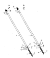
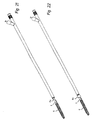
- Fig. 1 shows a perspective view of a first embodiment of the device of the invention with a preinstalled stent,
- Fig. 2 shows the device of Fig. 1 with a stent,
- Fig. 3 shows a perspective view of the tubular, cannula-like mantle,
- Fig. 4 shows a perspective view of the elongated member, which is placed inside the mantle of Fig. 3, together with means for controlling the movements of the elongated member,
- Fig. 5 shows a perspective view of the elongated member and the means for controlling the movements of the elongated member of Fig. 4 in a position where the means for holding the stent on the device are activated,
- Fig. 6 shows a plan view of the device of Fig. 1 with partial cross-section,
- Fig. 7 shows a plan view of the device of Fig. 2 with partial cross-section,
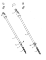
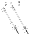
- Fig. 8 shows a plan view of the device seen from the direction similar to Figs. 6 and 7 in the phase where the stent is loosened for release from the end of the device,
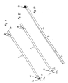
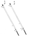
- Fig. 9 shows a perspective view of a second embodiment of the device of the invention with a fastened stent,
- Fig. 10 shows the device of Fig. 9 with means for locating an obstacle in a body cavity activated,
- Fig. 11 shows a perspective view of the tubular mantle of Figs. 9 and 10 with the means for locating an obstacle in a body cavity inactivated,
- Fig. 12 shows a perspective view of the tubular mantle of Fig. 11 where the means for locating an obstacle in a body cavity is activated,
- Fig. 13 shows a perspective view of the elongated member, which is placed inside the mantle of Fig. 11 and 12,
- Fig. 14 shows a plan view of the device of Fig. 9 with partial cross-section,
- Fig. 15 shows a plan view of the device of Fig. 10 with partial cross-section, and
- Fig. 16 shows a plan view of the device seen from the direction similar to Figs. 14 and 15 in the phase where the stent is loosened for release from the end of the device.
- Figs. 17-28 depict perspective views of additional embodiments of the invention comprising various combinations of the embodiments depicted in the foregoing Figures.
- Referring now to Figs. 1-8, in which a first embodiment of the device of the invention is illustrated, the device comprises as main components a
mantle 1, anelongated member 2,fastening elements 3 for thestent 4, control means 5 and sensing means 6. - The length of the
mantle 1 is such that the front end of themantle 1 can reach the area of the sphincter before the prostate when the device is inserted into the male urethra via the external urethral orifice. Thestent 4 is fastened in accordance with Fig. 2 to the firstfront end portion 2a of theelongated member 2. The outer dimensions of thetubular mantle 1 andstent 4 are selected in a manner that they can easily be brought into the male urethra. The control means 5 are outside the external urethra orifice when thestent 4 is installed, so that when thestent 4 is loosened for release from the device, as shown in Fig. 8, the control means 5 may be easily manipulated manually. - The
elongated member 2 shown in Figs. 6 and 7 is longer than the mantle I thereby having first andsecond end portions mantle 1. The first,front end portion 2a is substantially placed inside thestent 4, which in this embodiment is designed as a helical coil. Further, theelongated member 2 is divided into twosections first section 2c of theelongated member 2 has unitary construction and is formed as a stick-like element in connection with thefront end portion 2a. The distal part of thefront end portion 2a of theelongated member 2 is outside the front end of themantle 1, which itself is divided into asecond section 2d by a division of the unitary construction of thefirst section 2c into an outer tubular means 7a and an inner elongated means 7b, which resides inside said outertubular means 7a. The outer tubular means 7a are provided with cuts, e.g., 8a, 8b in Fig. 1. Said cuts protrude from the outer tubular means 7a in the longitudinal direction. Those cuts (four of which are presented in the first embodiment of the device shown in Figs. 1-8) are equidistantly divided around the periphery of the outer tubular means 7a. The cuts have their distal end at the point of the division between the first and second sections, 2c and 2d. The proximal end of the cuts is settled at a certain distance from thefront end 1a of themantle 1, so that thestent 4 can be attached to the device as explained in more detail below. - Means 5 for controlling the movements of the elongated member are affixed to the rear,
second end portion 2b of theelongated member 2. The main parts of the control means 5 are asleeve 10 and slide means 11 therein. As shown in Figs. 1-8, especially in Figs. 6 and 7, therear end part 9 of the outer tubular means 7a together with therear end part 1 b (Fig. 6) of themantle 1 are fixed to thefront end wall 13 of thesleeve 10, and the inner elongated means 7b is fixed to the front end of the slide means 11. The inner elongated means 7b is arranged to go through thehole 12 in thefront end wall 13 of thesleeve 10 and inside thehole 10a of thesleeve 10, wherein the slide means 11 is arranged to be moved manually in relation to thesleeve 10 in the longitudinal direction of the device. With reference to the embodiment of Figs. 1 and 2, thesleeve 10 has at a longitudinal wall alongitudinal groove 14 which opens towards the rear end of thesleeve 10. The slide means 11 is provided with anelevation 15 which is positioned into thegroove 14, as shown in Fig. 1. Further, the slide means 11 is provided with ahandle part 16 protruding from the rear end of thesleeve 10, the handle preferably including a prepared surface for manual gripping and using the control means 5. - As for the stent 4 (Fig. 8), it comprises an elongated, coiled wire part 4a to be placed at the area of the prostate, a
longitudinal rod part 4b connected to the elongated wire part 4a from the first end of the same and to be placed into a body cavity, such as at the area of sphincter muscle of the urethra, and further acoiled locking part 4c connected to the second end of the logitudinal rod part for placing in the urethra in front of the sphincter muscle. Thestent 4 is preferably made of a bioabsorbable polymer material. - In the embodiment of Figs. 1-8, to install the
stent 4 on the device for further insertion into a body cavity, thestent 4 is pushed onto thefirst portion 2a of theelongated member 2 in a manner that the rear end of the stent, i.e., the lockingpart 4c, passes the cuts, e.g., 8a, 8b, in the longitudinal direction of theelongated member 2. Thus, the lockingpart 4c is located in the area of theelongated member 2 between the cuts and thefront end part 1a of themantle 1. This phase of attaching the stent to the device is shown in Figs. 1 and 6. By pulling the slide means 11 out of thehole 10a of thesleeve 10 and by turning the slide means 11 around the longitudinal axis of the device, thefront end 15a of theelevation 15, which has passed by therear end 10b of thesleeve 10, is brought against saidrear end 10b, thereby activating the locating means 6 at the cuts (e.g., 8a, 8b). This activation is due to the shortening of the distance between the front end of thesecond section 2d and thefront end wall 13 of thesleeve 10, which is effected by pulling the inner elongated means 7b as described above. Such shortening causes the strips 16 (Fig. 4) between the cuts (e.g., 8a, 8b) to bend radially outwards at their middle sections. Thus, the lockingpart 4c of thestent 4 is locked between the outwardly bending strips 16 (Figs. 5 and 7) and thefront end part 1a of themantle 1, and simultaneously thestrips 16, form wing-like locating means 6 just ahead of the lockingpart 4c projecting radially outwards from the outer surface of the device. - The locating means 6 is used to locate the correct position of the
stent 4, by preventing the lockingpart 4c of the stent from progressing past, e.g., the sphincter muscle. When thestent 4 is at the correct position, the slide means 11 is brought back to the position shown in Figs. 1 and 6, whereby thestrips 6 are again lying in the longitudinal direction of the device, thereby releasing the lockingpart 4c of the stent from the locked position. Simultaneously, thefirst position 2a of theelongated member 2 is free to be retracted from the interior of the same, as shown in Fig. 8, and further the device can be retracted from the urethra. - A second embodiment of the invention is shown in Figs. 9-16. The device has the same main components as the first embodiment shown in Figs. 1-8. In the second embodiment of the invention, the
mantle 1, which in the first embodiment is constructed as a single tube, is (as especially seen in Fig. 11) comprised of a locating means 6 and a ring-shapedmember 17 protruding from thefirst end 1a of themantle 1. Further, theelongated member 2 is constructed as a single, stick-like element, as shown in Fig. 13, having a firstfront end portion 2a protruding from thefirst end 1a of themantle 1 inside thestent 4 in a similar manner as explained in connection with the first embodiment above. With reference to Figs. 9 and 10, theelongated member 2 is shown penetrating through thehole 17a of the ring-shapedmember 17 when thestent 4 is locked in connection with the device. The firstfront section 2a of theelongated member 2 passes through thehole 17a of the ring-shapedmember 17, forming a closed ring that locks the coiled lockingpart 4c of thestent 4 inside the said closed ring. By retracting the elongated member backwards, as shown in Fig. 16 (arrow A), the closed ring is opened when the the ring-shapedmember 17 is released from connection to theelongated member 2. In this way, the lockingpart 4c and thewhole stent 4 is freed from the insertion device. For purposes of the insertion and retraction of theelongated member 2, the rear end of that member is equipped with a handle and lockingpart 18, which is fastened frictionally to therear end 16 of themantle 1 when theelongated member 2 is inserted into themantle 1 and thestent 4 is fastened to the device. - The locating means 6 are placed at the front end of the
mantle 1, as shown in Figs. 14 and 15, at aspace 19 having its expansion limited by asection 20 of the surface of themantle 1. Thesection 20 is provided with at least oneaperture 21 connected by atubular line 22 inside themantle 1 to the secondrear end 1 b of themantle 1. Thetubular line 22 is provided for transfer of a pressure medium to and from thespace 19. A tubularelastic member 23, like a balloon, is overlying saidsection 20 of the surface of themantle 1 and is fastened tightly from both ends of said tubularelastic member 23 onto the surface of themantle 1, around the periphery of the same. Anadapter 24 is fixed in connection with themantle 1 at therear end 1b of the same and at the rear end of thetubular line 22 for providing and releasing the pressure medium to and from thespace 19. - The second embodiment can be used in a similar manner as explained above in connection with the first embodiment of the invention. The balloon-like locating means 6 is expanded as shown in Fig. 15 to locate the correct position of the
stent 4. After locating that correct position, the locating means 6 is deflated and theelongated member 2 is retracted, as shown in Fig. 16, whereby thestent 4 is released due to the opening of the closed ring. The device can be retracted from the urethra after the stage shown in Fig. 16. - In the above embodiments, the locating means (balloon or cut strips or equivalent) is used to hold the stent onto the device and to localize the stent within the body cavity, thereby simplifying the device, making it easy for a surgeon to handle and reducing its risk in use during surgery. Further, unlocking the stent from the device is simple and easy, making stent placement within the body cavity more precise and exact. Indeed, only a half-turn of the tube is necessary to release the stent (or deflate the balloon), as compared to the more burdensome release techniques of the prior art, such as the device of the '374 patent (requiring several turns to release the stent). The outer tube of the insertion device may be made from a material that is rigid or semi-rigid, thereby facilitating stent placement, location and unlocking from the device.
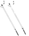
- Figs 17 and 18 show yet another embodiment of the device in which the cuts (e.g., 8A,8B) are made onto the
mantle 1 at the front end of the same in a similar manner as described above. A cord (not shown) may be led thorough themantle 1 in a manner that a loop is provided which locks the lockingpart 4c of thestent 4, and thus the whole stent, in connection with the insertion device. Both ends of the cord may be fixed to the slide means 11. When the slide means 11, starting from the position shown in Fig 17, is pulled and turned as described above the lockingpart 4c forces the cuts (e.g., 8A,8B) to bend outwards to form the locating means 6A as shown in Fig 18. - Figs 19 and 20 show yet another embodiment of the invention, comprising a combination of the embodiments of Figs 1 and 2 with that of Figs 17 and 18. The function of this embodiment of the device can be understood on basis of the teachings given in connection with the corresponding parts of the specification above. The outer tubular means 7a are provided with first cuts (e.g., 8a, 8b), said first cuts protruding from the outer tubular means 7a in the longitudinal direction of the outer tubular means 7a. Second cuts (e.g., 8A,8B) also are made into the
mantle 1 at the front end of the same in a similar manner as the first cuts. When the slide means 11, starting from the position shown in Fig 19 is pulled, the first cuts (e.g., 8a,8b) lock thelocking part 4c of thestent 4, thus providing a first locating means 6a as described in connection with Figs 1 and 2. Then the second cuts are bent outwards due to the continued movement of the first locating means 6a together with the lockingpart 4c towards thesleeve 10, thus forming the second locating means 6A. When inserting this embodiment of the device, the first locating means 6a meets the sphincter muscle of the urethra and thestent 4 can be released as described above. - Figs 21 and 22 show another embodiment of the invention, in which the balloon 6a fastens the
stent 4 in place of the wing construction of the embodiment shown in Figs 1 and 2. The locating means of this embodiment are formed onto the surface of the outer tubular means 7a of theelongate member 2. When the balloon 6a meets the sphincter muscle of the urethra, thestent 4 can be released by emptying the pressure in the expanding space. - Figs 23 and 24 show another embodiment of the invention comprising a partial combination of the embodiment of Figs 9 and 10, together with the embodiment of Figs 21 and 22. In this embodiment of the invention, the first balloon 6a is formed onto the surface of the outer tubular means 7a of the
elongated member 2, and thesecond balloon 6A is formed onto the surface of themantle 1. Figs 25 and 26 depict yet another embodiment of the invention, which is a partial combination of embodiments shown in Figs 1 and 2 with that of Figs 9 and 10. Likewise, Figs 27 and 28 show an additional embodiment of the invention, which is a partial combination of the embodiment shown in Figs 21 and 22 with that of Figs 17 and 18.
Claims (10)
- A device for inserting a stent (4) in a body cavity, said device comprising:- means (6) for locating the position of an obstacle in said body cavity,- an outer elongated mantle (1) having a first distal end to be inserted into a body cavity and second ends and- an elongated member (2) movably located inside said mantle (1), said elongated member (2) having first and second end portions (2a, 2b) protruding from said respective ends of said mantle (1), said first end portion (2a) of said elongated member (2) being capable of removably receiving said stent (4) distally of said means (6) for locating the position of an obstacle.
- The device of claim 1, wherein the locating means (6) projects radially outward from the member (2) or the mantle (1).
- The device of claim 1 or 2, wherein the locating means (6) comprises a balloon capable of temporarily protruding from the member (2) or the mantle (1).
- The device of claim 1 or 2, wherein the locating means (6) comprises cut stripes (8a, 8b) capable of temporarily protruding from the member (2) or the mantle (1).
- The device of claim 4, wherein- said second portion (2b) of said member (2) comprises an outer section (7a) and an inner section (7b), each having first and second ends, said outer section (7a) at least partially surrounding said inner section, said first end of said outer section (7a) and said first end of said inner section (7b) being connected to said first portion (2a) of said member (2);- said outer section (7a) has a portion thereof with a plurality of longitudinal cuts (8a, 8b) therethrough;- said inner section (7b) of said member (2) is capable of moving longitudinally with respect to said outer section (7a) of said member (2) so that said outer section (7a) is compressed longitudinally by said first portion (2a) of said member (2), and said portion of said outer section (7a) having cuts therethrough protrudes with respect to said first portion (2a) of said member (2).
- The device of any of claims 1 to 5, wherein the stent (4) is temporarily prevented from sliding off said member (2).
- The device of any of claims 1 to 6, wherein the sent (4) is temporarily prevented from sliding off said member (2) by said locating means (6).
- The device of claim 6, whereby, prior to insertion, a portion of said stent (4c) is located on either side of said means (6) for locating the position of an obstacle in said body cavity.
- The device of any of claims 1 to 6, wherein said stent is temporarily prevented from sliding off said member by a cord.
- The device of any of claims 1 to 6, further comprising a ring (17) attached to said first end of said mantle (1) for removably receiving said member (2), wherein when said member (2) may be advanced through a portion of said stent (4), through said ring (17), and through another portion of said stent (4) so that a portion of said stent (4) is located on either side of said ring (17).
Applications Claiming Priority (3)
| Application Number | Priority Date | Filing Date | Title |
|---|---|---|---|
| US465789 | 1999-12-17 | ||
| US09/465,789 US6685734B1 (en) | 1999-12-17 | 1999-12-17 | Urethral stent delivery system |
| PCT/EP2000/012752 WO2001043664A1 (en) | 1999-12-17 | 2000-12-14 | Urethral stent delivery system |
Publications (2)
| Publication Number | Publication Date |
|---|---|
| EP1237505A1 EP1237505A1 (en) | 2002-09-11 |
| EP1237505B1 true EP1237505B1 (en) | 2006-03-22 |
Family
ID=23849156
Family Applications (1)
| Application Number | Title | Priority Date | Filing Date |
|---|---|---|---|
| EP00988796A Expired - Lifetime EP1237505B1 (en) | 1999-12-17 | 2000-12-14 | Urethral stent delivery system |
Country Status (8)
| Country | Link |
|---|---|
| US (1) | US6685734B1 (en) |
| EP (1) | EP1237505B1 (en) |
| JP (1) | JP2003516802A (en) |
| AT (1) | ATE320775T1 (en) |
| AU (1) | AU2511301A (en) |
| DE (1) | DE60026886T2 (en) |
| ES (1) | ES2260089T3 (en) |
| WO (1) | WO2001043664A1 (en) |
Families Citing this family (19)
| Publication number | Priority date | Publication date | Assignee | Title |
|---|---|---|---|---|
| US8088060B2 (en) | 2000-03-15 | 2012-01-03 | Orbusneich Medical, Inc. | Progenitor endothelial cell capturing with a drug eluting implantable medical device |
| US9522217B2 (en) | 2000-03-15 | 2016-12-20 | Orbusneich Medical, Inc. | Medical device with coating for capturing genetically-altered cells and methods for using same |
| US6679909B2 (en) | 2001-07-31 | 2004-01-20 | Advanced Cardiovascular Systems, Inc. | Rapid exchange delivery system for self-expanding stent |
| US6929651B2 (en) * | 2002-09-27 | 2005-08-16 | Ethicon, Inc. | Urethral catheter stent delivery system |
| US7867271B2 (en) | 2003-11-20 | 2011-01-11 | Advanced Cardiovascular Systems, Inc. | Rapid-exchange delivery systems for self-expanding stents |
| US7753906B2 (en) * | 2004-09-14 | 2010-07-13 | Richard Esposito | Catheter having anchoring and stabilizing devices |
| CA2596885C (en) * | 2005-02-04 | 2014-07-08 | Poly-Med, Inc. | Fiber-reinforced composite absorbable endoureteral stent |
| US8083806B2 (en) * | 2005-02-04 | 2011-12-27 | Poly-Med, Inc. | Radiation and radiochemically sterilized fiber-reinforced, composite urinogenital stents |
| US8083805B2 (en) * | 2005-08-16 | 2011-12-27 | Poly-Med, Inc. | Absorbable endo-urological devices and applications therefor |
| US20070258935A1 (en) * | 2006-05-08 | 2007-11-08 | Mcentire Edward Enns | Water dispersible films for delivery of active agents to the epidermis |
| US20070259029A1 (en) * | 2006-05-08 | 2007-11-08 | Mcentire Edward Enns | Water-dispersible patch containing an active agent for dermal delivery |
| US20080057090A1 (en) * | 2006-09-01 | 2008-03-06 | Mcentire Edward Enns | Wrinkle masking film composition for skin |
| KR100780318B1 (en) * | 2006-12-11 | 2007-11-28 | 주식회사 에스앤지바이오텍 | Inserting device of artificial blood stent |
| US8287602B2 (en) * | 2007-12-12 | 2012-10-16 | Boston Scientific Scimed, Inc. | Urinary stent |
| US20120010645A1 (en) | 2009-03-20 | 2012-01-12 | Proarc Medical Ltd. | Methods and devices for urethral treatment |
| WO2012123950A2 (en) | 2011-03-17 | 2012-09-20 | Proarc Medical Ltd. | Methods and devices for urethral |
| JP2015513301A (en) * | 2012-01-30 | 2015-05-07 | ヒポクラット | Negatively charged vascular stent |
| CA2939823C (en) | 2013-03-14 | 2021-11-16 | Proarc Medical Ltd. | Methods and devices for urethral treatment |
| EP3145453B1 (en) * | 2014-05-21 | 2021-01-20 | Boston Scientific Scimed, Inc. | Stent delivery system |
Family Cites Families (29)
| Publication number | Priority date | Publication date | Assignee | Title |
|---|---|---|---|---|
| DE2827908C2 (en) | 1975-04-12 | 1982-06-09 | Karl Dr.Med. 5300 Bonn Fabian | catheter |
| US4531933A (en) | 1982-12-07 | 1985-07-30 | C. R. Bard, Inc. | Helical ureteral stent |
| US4512338A (en) | 1983-01-25 | 1985-04-23 | Balko Alexander B | Process for restoring patency to body vessels |
| US4790810A (en) | 1985-11-04 | 1988-12-13 | American Medical Systems, Inc. | Ureteral connector stent |
| DE3640745A1 (en) | 1985-11-30 | 1987-06-04 | Ernst Peter Prof Dr M Strecker | Catheter for producing or extending connections to or between body cavities |
| US4820262A (en) | 1985-12-12 | 1989-04-11 | Medical Engineering Corporation | Ureteral stent |
| FR2595564A1 (en) | 1986-03-11 | 1987-09-18 | Lavarenne Vincent | URETRAL ENDOPROTHESIS |
| US4713049A (en) | 1986-08-05 | 1987-12-15 | Medical Engineering Corporation | Ureteral stent kit |
| US5007898A (en) | 1988-06-02 | 1991-04-16 | Advanced Surgical Intervention, Inc. | Balloon dilatation catheter |
| US5527336A (en) | 1986-12-09 | 1996-06-18 | Boston Scientific Corporation | Flow obstruction treatment method |
| US5030227A (en) | 1988-06-02 | 1991-07-09 | Advanced Surgical Intervention, Inc. | Balloon dilation catheter |
| US4813925A (en) | 1987-04-21 | 1989-03-21 | Medical Engineering Corporation | Spiral ureteral stent |
| US4969458A (en) | 1987-07-06 | 1990-11-13 | Medtronic, Inc. | Intracoronary stent and method of simultaneous angioplasty and stent implant |
| DK163713C (en) | 1987-09-02 | 1992-09-07 | Ole Gyring Nieben | DEVICE FOR THE POSITION OF A PARTICULAR CATHETTE IN A BODY |
| US4820298A (en) | 1987-11-20 | 1989-04-11 | Leveen Eric G | Internal vascular prosthesis |
| US4932958A (en) | 1988-05-10 | 1990-06-12 | American Medical Systems, Inc. | Prostate balloon dilator |
| US4950227A (en) | 1988-11-07 | 1990-08-21 | Boston Scientific Corporation | Stent delivery system |
| US4973301A (en) | 1989-07-11 | 1990-11-27 | Israel Nissenkorn | Catheter and method of using same |
| US5263931A (en) | 1990-02-14 | 1993-11-23 | Advanced Cardiovascular Systems, Inc. | Balloon catheter for dilating a prostatic urethra |
| US5160341A (en) | 1990-11-08 | 1992-11-03 | Advanced Surgical Intervention, Inc. | Resorbable urethral stent and apparatus for its insertion |
| US5209725A (en) | 1991-04-11 | 1993-05-11 | Roth Robert A | Prostatic urethra dilatation catheter system and method |
| DE9114435U1 (en) | 1991-11-19 | 1992-01-16 | Engel, Konrad, Dr.Med., 8178 Gaissach, De | |
| US5304214A (en) | 1992-01-21 | 1994-04-19 | Med Institute, Inc. | Transurethral ablation catheter |
| US5322501A (en) | 1992-10-02 | 1994-06-21 | Mahmud Durrani Ayaz | Continent urethral stent for treating and preventing urethral stricture after surgery |
| SE505436C2 (en) | 1993-04-27 | 1997-08-25 | Ams Medinvent Sa | prostatic stent |
| IL108832A (en) * | 1994-03-03 | 1999-12-31 | Medinol Ltd | Urological stent and deployment device therefor |
| US5591199A (en) | 1995-06-07 | 1997-01-07 | Porter; Christopher H. | Curable fiber composite stent and delivery system |
| FR2736554B1 (en) | 1995-07-10 | 1997-08-29 | Devonec Marian | CATHETER FORM OF A SEPARABLE CATHETERIZATION MEANS AND INTRODUCTION MEANS USEFUL FOR THE TREATMENT OF PROSTATIC OBSTACLES IN MAN |
| US5865815A (en) | 1997-04-25 | 1999-02-02 | Contimed, Inc. | Prostatic obstruction relief catheter |
-
1999
- 1999-12-17 US US09/465,789 patent/US6685734B1/en not_active Expired - Fee Related
-
2000
- 2000-12-14 DE DE60026886T patent/DE60026886T2/en not_active Expired - Fee Related
- 2000-12-14 JP JP2001544606A patent/JP2003516802A/en active Pending
- 2000-12-14 WO PCT/EP2000/012752 patent/WO2001043664A1/en active IP Right Grant
- 2000-12-14 EP EP00988796A patent/EP1237505B1/en not_active Expired - Lifetime
- 2000-12-14 AU AU25113/01A patent/AU2511301A/en not_active Abandoned
- 2000-12-14 AT AT00988796T patent/ATE320775T1/en not_active IP Right Cessation
- 2000-12-14 ES ES00988796T patent/ES2260089T3/en not_active Expired - Lifetime
Also Published As
| Publication number | Publication date |
|---|---|
| AU2511301A (en) | 2001-06-25 |
| DE60026886D1 (en) | 2006-05-11 |
| ES2260089T3 (en) | 2006-11-01 |
| EP1237505A1 (en) | 2002-09-11 |
| ATE320775T1 (en) | 2006-04-15 |
| US6685734B1 (en) | 2004-02-03 |
| JP2003516802A (en) | 2003-05-20 |
| DE60026886T2 (en) | 2007-03-15 |
| WO2001043664A1 (en) | 2001-06-21 |
Similar Documents
| Publication | Publication Date | Title |
|---|---|---|
| EP1237505B1 (en) | Urethral stent delivery system | |
| US11925376B2 (en) | Methods and devices for urethral treatment | |
| AU2020200817B2 (en) | Indwelling body lumen expander | |
| KR100276151B1 (en) | System for catheter fixation | |
| US6093194A (en) | Insertion device for stents and methods for use | |
| US6162231A (en) | Stent insertion device | |
| IL263022A (en) | Radial cutter implant | |
| US7507247B2 (en) | Urethral catheter stent delivery system | |
| JP2011521680A (en) | System and method for transluminal access | |
| EP1951150A1 (en) | Stent with anchoring portion | |
| CN101854868A (en) | Tubal ligation | |
| US20120203357A1 (en) | Urethral anastomosis device | |
| US10314570B2 (en) | Surgical needle system with anchor retention features | |
| US20240023952A1 (en) | Anatomical tissue anchor and related methods |
Legal Events
| Date | Code | Title | Description |
|---|---|---|---|
| PUAI | Public reference made under article 153(3) epc to a published international application that has entered the european phase |
Free format text: ORIGINAL CODE: 0009012 |
|
| 17P | Request for examination filed |
Effective date: 20020705 |
|
| AK | Designated contracting states |
Kind code of ref document: A1 Designated state(s): AT BE CH CY DE DK ES FI FR GB GR IE IT LI LU MC NL PT SE TR |
|
| RAP1 | Party data changed (applicant data changed or rights of an application transferred) |
Owner name: LINVATEC BIOMATERIALS LTD. |
|
| 17Q | First examination report despatched |
Effective date: 20040116 |
|
| GRAP | Despatch of communication of intention to grant a patent |
Free format text: ORIGINAL CODE: EPIDOSNIGR1 |
|
| GRAS | Grant fee paid |
Free format text: ORIGINAL CODE: EPIDOSNIGR3 |
|
| GRAA | (expected) grant |
Free format text: ORIGINAL CODE: 0009210 |
|
| AK | Designated contracting states |
Kind code of ref document: B1 Designated state(s): AT BE CH CY DE DK ES FI FR GB GR IE IT LI LU MC NL PT SE TR |
|
| PG25 | Lapsed in a contracting state [announced via postgrant information from national office to epo] |
Ref country code: BE Free format text: LAPSE BECAUSE OF FAILURE TO SUBMIT A TRANSLATION OF THE DESCRIPTION OR TO PAY THE FEE WITHIN THE PRESCRIBED TIME-LIMIT Effective date: 20060322 Ref country code: AT Free format text: LAPSE BECAUSE OF FAILURE TO SUBMIT A TRANSLATION OF THE DESCRIPTION OR TO PAY THE FEE WITHIN THE PRESCRIBED TIME-LIMIT Effective date: 20060322 Ref country code: LI Free format text: LAPSE BECAUSE OF FAILURE TO SUBMIT A TRANSLATION OF THE DESCRIPTION OR TO PAY THE FEE WITHIN THE PRESCRIBED TIME-LIMIT Effective date: 20060322 Ref country code: NL Free format text: LAPSE BECAUSE OF FAILURE TO SUBMIT A TRANSLATION OF THE DESCRIPTION OR TO PAY THE FEE WITHIN THE PRESCRIBED TIME-LIMIT Effective date: 20060322 Ref country code: CH Free format text: LAPSE BECAUSE OF FAILURE TO SUBMIT A TRANSLATION OF THE DESCRIPTION OR TO PAY THE FEE WITHIN THE PRESCRIBED TIME-LIMIT Effective date: 20060322 |
|
| REG | Reference to a national code |
Ref country code: GB Ref legal event code: FG4D |
|
| REG | Reference to a national code |
Ref country code: CH Ref legal event code: EP |
|
| REG | Reference to a national code |
Ref country code: IE Ref legal event code: FG4D |
|
| REF | Corresponds to: |
Ref document number: 60026886 Country of ref document: DE Date of ref document: 20060511 Kind code of ref document: P |
|
| PG25 | Lapsed in a contracting state [announced via postgrant information from national office to epo] |
Ref country code: DK Free format text: LAPSE BECAUSE OF FAILURE TO SUBMIT A TRANSLATION OF THE DESCRIPTION OR TO PAY THE FEE WITHIN THE PRESCRIBED TIME-LIMIT Effective date: 20060622 Ref country code: SE Free format text: LAPSE BECAUSE OF FAILURE TO SUBMIT A TRANSLATION OF THE DESCRIPTION OR TO PAY THE FEE WITHIN THE PRESCRIBED TIME-LIMIT Effective date: 20060622 |
|
| PG25 | Lapsed in a contracting state [announced via postgrant information from national office to epo] |
Ref country code: PT Free format text: LAPSE BECAUSE OF FAILURE TO SUBMIT A TRANSLATION OF THE DESCRIPTION OR TO PAY THE FEE WITHIN THE PRESCRIBED TIME-LIMIT Effective date: 20060822 |
|
| NLV1 | Nl: lapsed or annulled due to failure to fulfill the requirements of art. 29p and 29m of the patents act | ||
| REG | Reference to a national code |
Ref country code: CH Ref legal event code: PL |
|
| ET | Fr: translation filed | ||
| REG | Reference to a national code |
Ref country code: ES Ref legal event code: FG2A Ref document number: 2260089 Country of ref document: ES Kind code of ref document: T3 |
|
| PGFP | Annual fee paid to national office [announced via postgrant information from national office to epo] |
Ref country code: GB Payment date: 20061106 Year of fee payment: 7 |
|
| PGFP | Annual fee paid to national office [announced via postgrant information from national office to epo] |
Ref country code: FI Payment date: 20061122 Year of fee payment: 7 |
|
| PGFP | Annual fee paid to national office [announced via postgrant information from national office to epo] |
Ref country code: FR Payment date: 20061201 Year of fee payment: 7 |
|
| PG25 | Lapsed in a contracting state [announced via postgrant information from national office to epo] |
Ref country code: IE Free format text: LAPSE BECAUSE OF NON-PAYMENT OF DUE FEES Effective date: 20061214 |
|
| PGFP | Annual fee paid to national office [announced via postgrant information from national office to epo] |
Ref country code: ES Payment date: 20061220 Year of fee payment: 7 |
|
| PGFP | Annual fee paid to national office [announced via postgrant information from national office to epo] |
Ref country code: DE Payment date: 20061229 Year of fee payment: 7 |
|
| PG25 | Lapsed in a contracting state [announced via postgrant information from national office to epo] |
Ref country code: MC Free format text: LAPSE BECAUSE OF NON-PAYMENT OF DUE FEES Effective date: 20061231 |
|
| PGFP | Annual fee paid to national office [announced via postgrant information from national office to epo] |
Ref country code: IT Payment date: 20061231 Year of fee payment: 7 |
|
| PLBE | No opposition filed within time limit |
Free format text: ORIGINAL CODE: 0009261 |
|
| STAA | Information on the status of an ep patent application or granted ep patent |
Free format text: STATUS: NO OPPOSITION FILED WITHIN TIME LIMIT |
|
| 26N | No opposition filed |
Effective date: 20061227 |
|
| PG25 | Lapsed in a contracting state [announced via postgrant information from national office to epo] |
Ref country code: GR Free format text: LAPSE BECAUSE OF FAILURE TO SUBMIT A TRANSLATION OF THE DESCRIPTION OR TO PAY THE FEE WITHIN THE PRESCRIBED TIME-LIMIT Effective date: 20060623 |
|
| PG25 | Lapsed in a contracting state [announced via postgrant information from national office to epo] |
Ref country code: FI Free format text: LAPSE BECAUSE OF NON-PAYMENT OF DUE FEES Effective date: 20071214 Ref country code: LU Free format text: LAPSE BECAUSE OF NON-PAYMENT OF DUE FEES Effective date: 20061214 Ref country code: TR Free format text: LAPSE BECAUSE OF FAILURE TO SUBMIT A TRANSLATION OF THE DESCRIPTION OR TO PAY THE FEE WITHIN THE PRESCRIBED TIME-LIMIT Effective date: 20060322 |
|
| GBPC | Gb: european patent ceased through non-payment of renewal fee |
Effective date: 20071214 |
|
| PG25 | Lapsed in a contracting state [announced via postgrant information from national office to epo] |
Ref country code: DE Free format text: LAPSE BECAUSE OF NON-PAYMENT OF DUE FEES Effective date: 20080701 |
|
| REG | Reference to a national code |
Ref country code: FR Ref legal event code: ST Effective date: 20081020 |
|
| PG25 | Lapsed in a contracting state [announced via postgrant information from national office to epo] |
Ref country code: CY Free format text: LAPSE BECAUSE OF FAILURE TO SUBMIT A TRANSLATION OF THE DESCRIPTION OR TO PAY THE FEE WITHIN THE PRESCRIBED TIME-LIMIT Effective date: 20060322 |
|
| PG25 | Lapsed in a contracting state [announced via postgrant information from national office to epo] |
Ref country code: GB Free format text: LAPSE BECAUSE OF NON-PAYMENT OF DUE FEES Effective date: 20071214 |
|
| REG | Reference to a national code |
Ref country code: ES Ref legal event code: FD2A Effective date: 20071215 |
|
| PG25 | Lapsed in a contracting state [announced via postgrant information from national office to epo] |
Ref country code: ES Free format text: LAPSE BECAUSE OF NON-PAYMENT OF DUE FEES Effective date: 20071215 Ref country code: FR Free format text: LAPSE BECAUSE OF NON-PAYMENT OF DUE FEES Effective date: 20071231 |
|
| PG25 | Lapsed in a contracting state [announced via postgrant information from national office to epo] |
Ref country code: IT Free format text: LAPSE BECAUSE OF NON-PAYMENT OF DUE FEES Effective date: 20071214 |