EP1237308B1 - Apparatus for variable wavelength dispersion and wavelength dispersion slope - Google Patents
Apparatus for variable wavelength dispersion and wavelength dispersion slope Download PDFInfo
- Publication number
- EP1237308B1 EP1237308B1 EP01120725A EP01120725A EP1237308B1 EP 1237308 B1 EP1237308 B1 EP 1237308B1 EP 01120725 A EP01120725 A EP 01120725A EP 01120725 A EP01120725 A EP 01120725A EP 1237308 B1 EP1237308 B1 EP 1237308B1
- Authority
- EP
- European Patent Office
- Prior art keywords
- wavelength
- dispersion
- optical path
- wavelength dispersion
- vipa
- Prior art date
- Legal status (The legal status is an assumption and is not a legal conclusion. Google has not performed a legal analysis and makes no representation as to the accuracy of the status listed.)
- Expired - Lifetime
Links
Images


Classifications
-
- G—PHYSICS
- G02—OPTICS
- G02B—OPTICAL ELEMENTS, SYSTEMS OR APPARATUS
- G02B6/00—Light guides; Structural details of arrangements comprising light guides and other optical elements, e.g. couplings
- G02B6/24—Coupling light guides
- G02B6/26—Optical coupling means
- G02B6/28—Optical coupling means having data bus means, i.e. plural waveguides interconnected and providing an inherently bidirectional system by mixing and splitting signals
- G02B6/293—Optical coupling means having data bus means, i.e. plural waveguides interconnected and providing an inherently bidirectional system by mixing and splitting signals with wavelength selective means
- G02B6/29304—Optical coupling means having data bus means, i.e. plural waveguides interconnected and providing an inherently bidirectional system by mixing and splitting signals with wavelength selective means operating by diffraction, e.g. grating
- G02B6/29305—Optical coupling means having data bus means, i.e. plural waveguides interconnected and providing an inherently bidirectional system by mixing and splitting signals with wavelength selective means operating by diffraction, e.g. grating as bulk element, i.e. free space arrangement external to a light guide
- G02B6/2931—Diffractive element operating in reflection
-
- G—PHYSICS
- G02—OPTICS
- G02B—OPTICAL ELEMENTS, SYSTEMS OR APPARATUS
- G02B6/00—Light guides; Structural details of arrangements comprising light guides and other optical elements, e.g. couplings
- G02B6/24—Coupling light guides
- G02B6/26—Optical coupling means
- G02B6/28—Optical coupling means having data bus means, i.e. plural waveguides interconnected and providing an inherently bidirectional system by mixing and splitting signals
- G02B6/293—Optical coupling means having data bus means, i.e. plural waveguides interconnected and providing an inherently bidirectional system by mixing and splitting signals with wavelength selective means
- G02B6/29304—Optical coupling means having data bus means, i.e. plural waveguides interconnected and providing an inherently bidirectional system by mixing and splitting signals with wavelength selective means operating by diffraction, e.g. grating
- G02B6/29305—Optical coupling means having data bus means, i.e. plural waveguides interconnected and providing an inherently bidirectional system by mixing and splitting signals with wavelength selective means operating by diffraction, e.g. grating as bulk element, i.e. free space arrangement external to a light guide
- G02B6/29311—Diffractive element operating in transmission
-
- G—PHYSICS
- G02—OPTICS
- G02B—OPTICAL ELEMENTS, SYSTEMS OR APPARATUS
- G02B6/00—Light guides; Structural details of arrangements comprising light guides and other optical elements, e.g. couplings
- G02B6/24—Coupling light guides
- G02B6/26—Optical coupling means
- G02B6/28—Optical coupling means having data bus means, i.e. plural waveguides interconnected and providing an inherently bidirectional system by mixing and splitting signals
- G02B6/293—Optical coupling means having data bus means, i.e. plural waveguides interconnected and providing an inherently bidirectional system by mixing and splitting signals with wavelength selective means
- G02B6/29346—Optical coupling means having data bus means, i.e. plural waveguides interconnected and providing an inherently bidirectional system by mixing and splitting signals with wavelength selective means operating by wave or beam interference
- G02B6/29358—Multiple beam interferometer external to a light guide, e.g. Fabry-Pérot, etalon, VIPA plate, OTDL plate, continuous interferometer, parallel plate resonator
-
- G—PHYSICS
- G02—OPTICS
- G02B—OPTICAL ELEMENTS, SYSTEMS OR APPARATUS
- G02B6/00—Light guides; Structural details of arrangements comprising light guides and other optical elements, e.g. couplings
- G02B6/24—Coupling light guides
- G02B6/26—Optical coupling means
- G02B6/28—Optical coupling means having data bus means, i.e. plural waveguides interconnected and providing an inherently bidirectional system by mixing and splitting signals
- G02B6/293—Optical coupling means having data bus means, i.e. plural waveguides interconnected and providing an inherently bidirectional system by mixing and splitting signals with wavelength selective means
- G02B6/29371—Optical coupling means having data bus means, i.e. plural waveguides interconnected and providing an inherently bidirectional system by mixing and splitting signals with wavelength selective means operating principle based on material dispersion
- G02B6/29373—Optical coupling means having data bus means, i.e. plural waveguides interconnected and providing an inherently bidirectional system by mixing and splitting signals with wavelength selective means operating principle based on material dispersion utilising a bulk dispersive element, e.g. prism
-
- G—PHYSICS
- G02—OPTICS
- G02B—OPTICAL ELEMENTS, SYSTEMS OR APPARATUS
- G02B6/00—Light guides; Structural details of arrangements comprising light guides and other optical elements, e.g. couplings
- G02B6/24—Coupling light guides
- G02B6/26—Optical coupling means
- G02B6/28—Optical coupling means having data bus means, i.e. plural waveguides interconnected and providing an inherently bidirectional system by mixing and splitting signals
- G02B6/293—Optical coupling means having data bus means, i.e. plural waveguides interconnected and providing an inherently bidirectional system by mixing and splitting signals with wavelength selective means
- G02B6/29379—Optical coupling means having data bus means, i.e. plural waveguides interconnected and providing an inherently bidirectional system by mixing and splitting signals with wavelength selective means characterised by the function or use of the complete device
- G02B6/29392—Controlling dispersion
- G02B6/29394—Compensating wavelength dispersion
-
- G—PHYSICS
- G02—OPTICS
- G02B—OPTICAL ELEMENTS, SYSTEMS OR APPARATUS
- G02B6/00—Light guides; Structural details of arrangements comprising light guides and other optical elements, e.g. couplings
- G02B6/24—Coupling light guides
- G02B6/26—Optical coupling means
- G02B6/28—Optical coupling means having data bus means, i.e. plural waveguides interconnected and providing an inherently bidirectional system by mixing and splitting signals
- G02B6/293—Optical coupling means having data bus means, i.e. plural waveguides interconnected and providing an inherently bidirectional system by mixing and splitting signals with wavelength selective means
- G02B6/29379—Optical coupling means having data bus means, i.e. plural waveguides interconnected and providing an inherently bidirectional system by mixing and splitting signals with wavelength selective means characterised by the function or use of the complete device
- G02B6/29398—Temperature insensitivity
-
- H—ELECTRICITY
- H04—ELECTRIC COMMUNICATION TECHNIQUE
- H04B—TRANSMISSION
- H04B10/00—Transmission systems employing electromagnetic waves other than radio-waves, e.g. infrared, visible or ultraviolet light, or employing corpuscular radiation, e.g. quantum communication
- H04B10/25—Arrangements specific to fibre transmission
- H04B10/2507—Arrangements specific to fibre transmission for the reduction or elimination of distortion or dispersion
- H04B10/2513—Arrangements specific to fibre transmission for the reduction or elimination of distortion or dispersion due to chromatic dispersion
- H04B10/25133—Arrangements specific to fibre transmission for the reduction or elimination of distortion or dispersion due to chromatic dispersion including a lumped electrical or optical dispersion compensator
-
- G—PHYSICS
- G02—OPTICS
- G02B—OPTICAL ELEMENTS, SYSTEMS OR APPARATUS
- G02B6/00—Light guides; Structural details of arrangements comprising light guides and other optical elements, e.g. couplings
- G02B6/24—Coupling light guides
- G02B6/26—Optical coupling means
- G02B6/27—Optical coupling means with polarisation selective and adjusting means
- G02B6/2706—Optical coupling means with polarisation selective and adjusting means as bulk elements, i.e. free space arrangements external to a light guide, e.g. polarising beam splitters
- G02B6/2713—Optical coupling means with polarisation selective and adjusting means as bulk elements, i.e. free space arrangements external to a light guide, e.g. polarising beam splitters cascade of polarisation selective or adjusting operations
-
- G—PHYSICS
- G02—OPTICS
- G02B—OPTICAL ELEMENTS, SYSTEMS OR APPARATUS
- G02B6/00—Light guides; Structural details of arrangements comprising light guides and other optical elements, e.g. couplings
- G02B6/24—Coupling light guides
- G02B6/26—Optical coupling means
- G02B6/27—Optical coupling means with polarisation selective and adjusting means
- G02B6/2753—Optical coupling means with polarisation selective and adjusting means characterised by their function or use, i.e. of the complete device
- G02B6/2793—Controlling polarisation dependent loss, e.g. polarisation insensitivity, reducing the change in polarisation degree of the output light even if the input polarisation state fluctuates
-
- G—PHYSICS
- G02—OPTICS
- G02B—OPTICAL ELEMENTS, SYSTEMS OR APPARATUS
- G02B6/00—Light guides; Structural details of arrangements comprising light guides and other optical elements, e.g. couplings
- G02B6/24—Coupling light guides
- G02B6/26—Optical coupling means
- G02B6/28—Optical coupling means having data bus means, i.e. plural waveguides interconnected and providing an inherently bidirectional system by mixing and splitting signals
- G02B6/293—Optical coupling means having data bus means, i.e. plural waveguides interconnected and providing an inherently bidirectional system by mixing and splitting signals with wavelength selective means
- G02B6/29379—Optical coupling means having data bus means, i.e. plural waveguides interconnected and providing an inherently bidirectional system by mixing and splitting signals with wavelength selective means characterised by the function or use of the complete device
- G02B6/29395—Optical coupling means having data bus means, i.e. plural waveguides interconnected and providing an inherently bidirectional system by mixing and splitting signals with wavelength selective means characterised by the function or use of the complete device configurable, e.g. tunable or reconfigurable
Definitions
- the present invention relates to an apparatus for providing wavelength dispersion for compensating for the wavelength dispersion accumulated in an optical fiber transmission network.
- a transmitter transmits a pulse to a receiver through an optical fiber.
- the wavelength dispersion of an optical fiber deteriorates the quality of a signal of a system.
- the transmission speed of a signal of an optical fiber depends on the wavelength of the signal. For example, if a pulse having a long wavelength (for example, the pulse of the wavelength indicating a red color pulse) is transmitted at a higher speed than a pulse having a short wavelength (for example, the pulse of the wavelength indicating a blue color pulse), it is normal dispersion. On the other hand, if a pulse having a short wavelength (for example, the pulse of the wavelength indicating a blue color pulse) is transmitted at a higher speed than a pulse having a long wavelength (for example, the pulse of the wavelength indicating a red color pulse), then it is abnormal dispersion.
- a pulse having a long wavelength for example, the pulse of the wavelength indicating a red color pulse
- a pulse contains red and blue pulses and is transmitted from a transmitter
- the pulse is divided when it is transmitted through an optical fiber into a red pulse and a blue pulse which are received by a photodetector at different times. If a red pulse is transmitted at a higher speed than a blue pulse, it is normal dispersion.
- a pulse is extended in an optical fiber and distorted by wavelength dispersion because a red component and a blue component are transmitted at different speeds. Since all pulses contain finite wavelength extension, such wavelength dispersion frequently occurs in the fiber optical communications system.
- an inverse dispersion device provides inverse dispersion for a pulse to nullify the dispersion generated by transmission through an optical fiber.
- a dispersion compensation fiber has a specific sectional index profile, thereby functioning as an inverse dispersion device and providing the inverse dispersion for nullifying the dispersion generated by the optical fiber.
- the dispersion compensation fiber is expensive in production cost, and has to be sufficiently long enough to successfully compensate for the wavelength dispersion. For example, when an optical fiber is 100 km long, the dispersion compensation fiber is approximately 20 through 30 km. Therefore, there is the problem of a large loss and size.
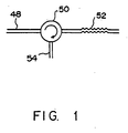
- FIG. 1 shows the chirp fiber grating used as an inverse dispersion device to compensate for the chromatic dispersion.
- a ray is transmitted through an optical fiber, wavelength-dispersed, and then provided for an input port 48 of an optical circulator 50.
- the optical circulator 50 provides the ray for a chirp fiber grating 52.
- the chirp fiber grating 52 returns the ray to the optical circulator 50 such that different wavelength components can be reflected by the channel fiber grating at different distances, different wavelength components can travel different distances, and the wavelength dispersion can be compensated for.
- the chirp fiber grating 52 can be designed such that a long wavelength component can be reflected at a long distance, and travel a longer distance than a short wavelength.
- the optical circulator 50 provides the ray reflected to an output port 54 from the chirp fiber grating 52. Therefore, the chirp fiber grating 52 can add inverse dispersion to a pulse.
- the chirp fiber grating 52 has very narrow band for a reflected pulse. Therefore, a sufficient wavelength band cannot be obtained to compensate for the ray containing a number of wavelengths such as a wavelength division-multiplexed light.
- a number of chirp fiber gratings can be cascaded for a wavelength division-multiplexed signal.
- the resultant system becomes costly.
- the chirp fiber grating obtained by incorporating a circulator is appropriate for a single-wavelength fiber optical communications system, etc.
- FIGS. 2 and 3 shows the conventional diffraction grating used to generate wavelength dispersion.
- a diffraction grating 56 has a grating surface 58.
- Parallel rays 60 having different wavelengths are input into the grating surface 58.
- the rays are reflected by each stage of the grating surface 58, and interferes each other.
- rays 62, 64, and 66 having different wavelengths are output at different angles from the diffraction grating 56.
- the diffraction grating can be used in the spatial grating pair array described later to compensate for the wavelength dispersion.
- FIG. 3A shows a spatial grating pair array used as an inverse dispersion device to compensate for wavelength dispersion.
- a ray 67 is diffracted from a first diffraction grating 68, and becomes a ray 69 for a short wavelength and a ray 70 for a long wavelength.
- These ray 67 and ray 70 are diffracted by a second diffraction grating 71, and travel in the same direction.
- the wavelength components having different wavelengths travel different distances, thereby compensating for the wavelength dispersion.
- a long wavelength (such as the ray 70, etc.) travels a longer distance than a short wavelength. Therefore, the spatial grating pair array shown in FIG. 3A indicates abnormal dispersion.
- FIG. 3B shows another spatial grating pair array used as an inverse dispersion device to compensate for chromatic dispersion.
- lenses 72 and 74 are positioned between the first and second diffraction gratings 68 and 71.
- a long wavelength (such as the ray 70) travels a shorter distance than a short wavelength (such as the ray 69). Therefore, the spatial grating pair array shown in FIG. 3B indicates normal dispersion.
- the spatial grating pair array as shown in FIGS. A and B are normally used to control the dispersion using a laser resonator.
- an actual spatial grating pair array cannot provide sufficient dispersion to compensate for a relatively large amount of chromatic dispersion generated by the fiber optical communications system.
- the angular dispersion generated by diffraction grating is normally very small, that is, approximately 0.05°/nm. Therefore, to compensate for the wavelength dispersion generated in the fiber optical communications system, the first and second diffraction grating 68 and 71 have to be largely apart. Accordingly, such a spatial grating pair array is not practical at all.
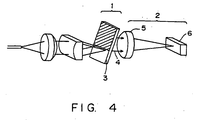
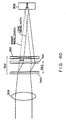
- FIG. 4 shows the conventional technology of an inverse dispersion device using a VIPA.
- the 'Virtually Imaged Phased Array' as shown in FIG. 4 that is, the device containing the portion referred to as VIPA 1, is suggested as an inverse dispersion device.
- the VIPA transmits from the VIPA the rays having different wavelengths spatially discriminated.
- This device includes an optical return device 2 for generating multiple reflection in the VIPA.
- the above mentioned device can be realized by comprising a device including the VIPA 1 for receiving the input ray of a wavelength in the range of continuous wavelengths, and continuously generating a corresponding output ray.
- the output ray can be spatially discriminated from the output ray of a different wavelength in the range of the continuous wavelengths (for example, traveling in different directions). If the output ray can be discriminated at a forward angle, it proves that the device provides angular dispersion.
- the above mentioned device is realized by comprising the VIPA 1 and the optical return device 2.
- the VIPA 1 contains a transmission area and a transparent element. By traveling through the transmission area, a ray can be input from and output to the VIPA 1.
- A. transparent element 3 has the first and the second surfaces. The second surface is reflective, and passes a part of an input ray. The input ray passes through the transmission area. Then, it is received by the VIPA 1, and is reflected many times between the first and second surfaces of the transparent element. A plurality of the transmitted rays interfere each other, and an output ray 4 is generated.
- the input ray has a wavelength in the range of continuous wavelengths, and the output ray can be spatially discriminated from the ray of another wavelength in the range of the continuous wavelengths.
- the optical return device 2 can return the output ray in the completely opposite direction to the second surface, pass it through the second surface, and input it into the VIPA 1.
- the output ray is multiple-reflected in the VIPA 1, and output to an input path through the transmission area of the VIPA 1.
- the above mentioned device can be realized by comprising a device including a VIPA for generating a plurality of output rays having the same wavelengths as the input ray and having different interference orders.
- the device also includes an optical return device for returning an output ray at one interference order to the VIPA, and not returning other output rays. Thus, only the ray corresponding to one interference order is returned to the VIPA.
- the above mentioned device can be realized by including a VIPA, an optical return device, and a lens 5.
- the VIPA receives an input ray, and generates a corresponding output ray transmitted from the VIPA.
- the optical return device receives the output ray from the VIPA, and returns it to the VIPA.
- the lens is positioned such that: (a) the output ray can be returned from the optical return device to the VIPA by passing through the lens from the VIPA and being collected at the optical return device by the lens; (b) the output ray can be returned from the optical return device to the VIPA by being directed from the optical return device to the lens, and then to the VIPA by the lens; and (c) the output ray from the VIPA to the lens can travel parallel to and in the opposite direction of the output ray returned from the lens to the VIPA. Furthermore, the output ray from the VIPA to the lens does not overlap the output ray returned from the lens to the VIPA.
- the above mentioned device can be realized by including the device having a VIPA, a mirror 6, and a lens.
- the VIPA receives an input ray, and generates an output ray traveling from a corresponding VIPA.
- the lens collects the output ray at the mirror, the mirror reflects the output ray, and the reflected ray is returned to the VIPA by the lens.
- the mirror is formed such that the device can perform constant wavelength dispersion.
- the VIPA has the function of performing angular dispersion as diffraction grating, and can compensate for wavelength dispersion. Especially, it is characterized by large angular dispersion, and easily provides a practical inverse dispersion device. However, it requires specific conditions of a practical inverse dispersion device for use in a wavelength multiplexed transmission system.
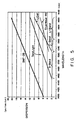
- FIG. 5 shows the wavelength dispersion of an optical fiber normally put for practical use.
- the wavelength dispersion of an optical fiber normally put for practical use is not constant by a wavelength as shown in FIG. 5, but normally has a small positive slope (the longer the wavelength, the larger positive value the wavelength dispersion indicates).
- the wavelength dispersion per 1 km is about +17 ps/nm while the wavelength dispersion slope indicates 0.06 ps/nm 2 .
- the wavelength dispersion changes approximately +2 ps/nm.
- Such a slope of wavelength dispersion can be referred to as a wavelength dispersion slope or a second order wavelength dispersion.
- the wavelength dispersion slope is not always positive (the longer the wavelength, the larger the wavelength dispersion), but a wavelength dispersion slope can be generated such that it can be negative in a wavelength extension longer than the zero dispersion wavelength in a dispersion shifted fiber with the zero dispersion wavelength shifted to the wavelength band of 1.5 ⁇ m by changing the structure of the fiber.
- wavelength dispersion graph shown in FIG. 5 is not actually linear, and the slope of wavelength dispersion (wavelength dispersion slope) is not strictly constant, but the third order wavelength dispersion seldom causes problems at a transmission speed of about 40 Gb/s, and can be ignored.
- the wavelength dispersion and a wavelength dispersion slope per unit length depend on the type of optical fiber as shown in FIG. 5, and the actual wavelength dispersion and wavelength dispersion slope depend on the length (transmission distance) of an optical fiber. If the wavelength dispersion of the actual optical fiber transmission line is compensated for by an inverse dispersion device, it is desired that a wavelength dispersion can be somewhat variable because the type and the transmission distance of an optical fiber largely depend on the period in which the optical fiber is installed and the situation of the site of the installed optical fiber.
- the compensation of the wavelength dispersion only is not sufficient, but a wavelength dispersion slope becomes a problem.
- the wavelength dispersion cannot be completely compensated for with different wavelengths of signal channels if the wavelength dispersion of an inverse dispersion component is constant. Therefore, it is desired that the inverse dispersion device for the wavelength multiplexed transmission has a wavelength dispersion slope.
- the wavelength dispersion slope changes in proportion to the length with the wavelength dispersion, it is also desired that the wavelength dispersion slope is somewhat variable.
- the value of a wavelength dispersion slope to be provided does not depend simply on the value of the wavelength dispersion because, if the type of optical fiber changes, not only the wavelength dispersion but also the wavelength dispersion slope changes as clearly shown in FIG. 5. That is, in the wavelength multiplexed transmission, it is the most desirable that the wavelength dispersion and the wavelength dispersion slope can be independently variable when the wavelength dispersion of an optical fiber transmission line is compensated for by an inverse dispersion device.
- an index profile including an inverse dispersion slope can be designed.
- changing its value requires various index profiles and lengths, and is not a practical operation.
- the method is costly, has a large loss, and large in size.
- the chirp fiber grating also requires various index profiles and lengths although it can provide an inverse dispersion slope by optimizing the design of the chirp of the chirp fiber grating. Therefore, it is not a practical method, either.
- the wavelength dispersion and the wavelength dispersion slope are changed by changing the temperature, the value of the wavelength dispersion slope simply depends on the value of the wavelength dispersion. As a result, the wavelength dispersion and the wavelength dispersion slope cannot be independently varied.
- a sufficient wavelength band to compensate for the ray containing a large number of wavelengths such as a wavelength division-multiplexed ray cannot be obtained.
- WO-A-01/50177 was filed on 13 December 2000 claiming priority dates of. 14 December 1999, 23 May 2000 and 4 December 2000, and was published on 12 July 2001. It discloses a VIPA generator which produces a light traveling from the VIPA generator, and a mirror which reflects the light back to the generator.
- an angular dispersive component such as a transmission type diffraction grating, a reflection type diffraction grating or a holographic grating is positioned between the VIPA and the mirror.
- WO-A-99/09448 discloses an apparatus which adds "opposite dispersion" to light, to compensate for chromatic dispersion of the light caused by traveling through an optical fiber.
- the apparatus includes a virtually imaged phase array (VIPA), and a light returning device.
- VIPA virtually imaged phase array
- the VIPA provides angular dispersion to the light, and the light returning device returns the light back to the VIPA to undergo multiple reflections inside the VIPA.
- the light returning device is typically a mirror. In this case, the mirror can be shaped so that the apparatus adds a constant dispersion to the light.
- a lens can be positioned so that (a) the light travels from the VIPA to the lens and the being focused by the lens to the light returning device, (b) the light returns from the light returning device to the lens and then, being directed by the lens, is parallel with the returned light traveling from the lens to the VIPA.
- an apparatus for providing wavelength dispersion to different wavelengths of light in a ray comprising multiple wavelengths as set out in Claim 1.
- An embodiment of the invention provides an apparatus for generating arbitrary wavelength dispersion and wavelength dispersion slope, and simultaneously performing dispersion compensation in multiple wavelength range of multiple channels on the wavelength dispersion and wavelength dispersion slope practically accumulated in an optical fiber.
- wavelength dispersion and a wavelength dispersion slope can be independently controlled, and can be provided for an optical signal. Therefore, an effective wavelength dispersion compensator can be provided when high-speed optical communications are realized using an optical fiber.
- FIG. 6 shows a virtually imaged phased array (VIPA).
- a VIPA 76 is a thin glass plate.
- An input ray 77 is collected on a line 78 through a lens 80 such as a semicylindrical lens, etc., and the input ray 77, thereby reaching the VIPA 76.
- the line 78 is hereinafter referred to as a focal line 78.
- the input ray 77 is radially transmitted from the focal line 78, and received by the VIPA 76.
- the VIPA 76 outputs luminous flux 82 of parallel rays.
- the output angle of the luminous flux 82 changes with the wavelength of the input ray 77.
- the VIPA 76 when the wavelength of the input ray 77 is ⁇ 1, the VIPA 76 outputs the luminous flux 82a having the wavelength of ⁇ 1 in a specified direction. When the wavelength of the input ray 77 is ⁇ 2, the VIPA 76 outputs the luminous flux 82a having the wavelength of ⁇ 2 in a specified direction. Therefore, the VIPA 76 generates the luminous flux 82a and 82b which can be spatially discriminated from each other.
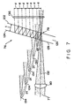
- FIG. 7 shows in detail the VIPA 76 for use in an embodiment of the present invention.
- the VIPA 76 comprises a plate 120 which is made of, for example, glass, and has reflecting films 122 and 124 on the surface. It is desired that the reflecting film 122 has a reflectance of 95% or higher, but has to be up to 100%. It is desired that the reflecting film 124 has the reflectance of approximately 100%. It is also desired that a radiation window 126 is formed on the plate 120, and has a reflectance of approximately 0%.
- the input ray 77 is collected by the lens 80 on the focal line 78 through the radiation window 126 such that multiple reflection can be generated between the reflecting films 122 and 124.
- the focal line 78 is desired to be on the plate 120 to which the reflecting film 122 is applied.
- the focal line 78 is desired to be positioned in the plate 120 to which the reflecting film 122 is applied.
- the focal line 78 is a line for collecting rays on the reflecting film 122 through the radiation window 126.
- the width of the focal line 78 collected by the lens 80 is also referred to as a beam waist of the input ray 77.
- the beam waist of the input ray 77 converges on the farther surface (that is, the surface of the reflecting film 122) of the plate 120.
- the area for example, an area a shown in FIG. 10 described below in detail
- the area for example, an area b shown in FIG. 10 described below in detail
- the reflecting film 124 into which the input ray 77 is first input when it is first reflected by the reflecting film 124.
- an optical axis 132 of the input ray 77 has a small slope angle ⁇ .
- 5% of the rays are transmitted through the reflecting film 122, and diverges after the beam waist.
- 95% of the rays are reflected toward the reflecting film 124.
- the rays After being reflected by the reflecting film 124, the rays reach the reflecting film 122 with a shift by d. Then, 5% of the rays are transmitted through the reflecting film 122.
- the rays diverge from a virtual image 134 at the beam waist.
- the virtual image 134 is arranged at predetermined intervals of 2t along the line vertical to the plate 120.
- t indicates the thickness of the plate 120.
- the position of the beam waist relative to the virtual image 134 is automatically set. It is not necessary to adjust the positions of the images.
- the rays from the virtual images 134 interfere with each other, and form parallel rays 136 transmitted in the different directions depending on the wavelengths of the input rays 77.
- the angular dispersion is proportional to the ratio between the two values, that is, proportional to cot ⁇ . As a result, the VIPA generates considerable angular dispersion.
- the term 'virtually imaged phased array' has come from the form of the arrangement of the virtual image 134.
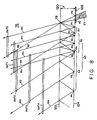
- FIG. 8 shows the cross section along the line IX - IX of the VIPA 76 shown in FIG. 6.
- the plate 120 has the reflecting films 122 and 124.
- the reflecting surfaces 122 and 124 are parallel to each other, and arranged at intervals of t indicating the thickness of the plate 120.
- the reflecting surfaces 122 and 124 are typical reflecting films applied to the plate 120.
- the reflectance of the reflecting surface 124 is approximately 100% excluding the radiation window 126.
- the reflectance of the reflecting surface 122 is 95% or higher. Therefore, the transmittance of the reflecting surface 122 is 5% or lower.
- 5% or lower of the input rays are transmitted through the reflecting surface 122, and 95% or higher of them are reflected.
- Changing the reflectance of the reflecting surfaces 122 and 124 does not affect the operation of the VIPA. However, the reflectance of the reflecting surface 122 is to be lower than 100% to transmit a part of the input rays.
- the radiation window 126 is provided in the reflecting surface 124. It is desired that the radiation window 126 passes rays, and does not reflect them, or has the lowest possible reflectance.
- the radiation window 126 receives and reflects the input ray 77 on the reflecting surfaces 122 and 124.
- FIG. 8 shows the cross section along the straight line IX - IX shown in FIG. 6. Therefore, the focal line 78 shown in FIG. 6 is expressed by dots in FIG. 8. The input rays 77 are radially transmitted from the focal line 78. Furthermore, as shown in FIG. 8, the focal line 78 is provided in the reflecting surface 122. It is not necessary to provide the focal line 78 in the reflecting surface 122, but changing the position of the focal line 78 causes a small change in the characteristic of the VIPA 76.
- the input ray 77 enters the plate 120 through the area A0 of the radiation window 126.
- the point P0 indicates a point in the area A0.
- the reflectance of the reflecting surface 122 95% or higher of -the input rays 77 are reflected by the reflecting surface 122, and input into the area A1 of the reflecting surface 124.
- the point P1 indicates a point in the area A1.
- the input rays 77 After being reflected in the area A1 of the reflecting surface 124, the input rays 77 reach the reflecting surface film 122, and a part of the input rays 77 is transmitted through the reflecting surface 122 as an output ray Out 1 referred to as a Ray R1.
- the input ray 77 is multiple-reflected between the reflecting surface 122 and the reflecting surface 124.
- a transmitted ray is generated. Therefore, for example, immediately after the input rays 77 are reflected in the areas A2, A3, and A4 of the reflecting surface 124, they are reflected by the reflecting surface 122, and output rays Out 2, Out 3, and Out 4 are generated.
- the point P2 indicates a point in the area A2
- the point P3 indicates a point in the area A3
- the point P4 indicates a point in the area A4.
- the output ray Out 2 is indicated by the ray R2
- the output ray Out 3 is indicated by the ray R3
- the output ray Out 4 is indicated by the ray R4.
- FIG. 8 shows only the output rays Out 0, Out 1, Out 2, Out 3, and Out 4, but there are a large number of rays depending on the intensity of the input ray 77 and the reflectance of the reflecting surfaces 122 and 124.
- the output rays interfere with each other, and generate luminous flux directed in different directions depending on the wavelength of the input ray 77. Therefore, the luminous flux can be referred to as an output ray generated by the interference among the output rays Out 1, Out 2, Out 3, and Out 4.
- FIG. 9 shows the interference of reflected rays by the VIPA.
- the ray transmitted from the focal line 78 is reflected by the reflecting surface 124.
- the reflectance of the reflecting surface 124 is approximately 100%, and basically has the function of a mirror.
- the output ray Out 1 has been emitted from the focal line I1 without the reflecting surfaces 122 and 124.
- the output rays Out 2, Out 3, and Out 4 have been emitted from the focal lines I2, I3, and I4.
- the focal lines I2, I3, and I4 are virtual images of the focal line I0.
- the focal line I1 is 2t apart from the focal line 10, where t indicates the distance between the reflecting surfaces 122 and 124.
- the subsequent focal lines are spaced 2t apart. Therefore, the focal line 12 is placed at a distance of 2t from the focal line I1.
- an output ray lower in intensity than the output ray immediately before is generated by the subsequent multiple reflection between the reflecting surfaces 122 and 124. Therefore, the output ray Out 2 is lower in intensity than the output ray Out 1.
- the output rays from focal lines overlap and interfere with each other.
- the focal lines I1, I2, I3, and I4 are virtual images of the focal line I0, the output rays Out 0, Out 1, Out 2, Out 3, and Out 4 have equal optical phases on the focal lines I1, I2, I3, and I4. Therefore, the interference generates luminous flux transmitting in different directions depending on the wavelength of the input ray 77.
- the VIPA contains the constructive condition which is the feature of designing a VIPA. By satisfying the constructive condition, luminous flux is generated with the interference of output rays intensifying each other.
- the input rays 77 radially diverge from the focal line 78 at a specified angle. Therefore, input rays having equal wavelengths travel in a number of different directions from the focal line 78, and are reflected by the reflecting surfaces 122 and 124.
- rays traveling in a specified direction intensify each other through the interference of output rays, and form luminous flux in the direction corresponding to the wavelength of an input ray.
- a ray traveling in a direction different from a specified direction based on the constructive condition is reduced in intensity by the interference of output rays.
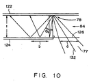
- FIG. 10 shows the cross section along the straight line IX - IX of the VIPA shown in FIG. 6, and shows the characteristic of the VIPA for determining the angle of incidence or the slope angle.
- the input ray 77 is collected by the cylindrical lens (not shown in the attached drawings, and converge on the focal line 78. As shown in FIG. 10, the input ray 77 covers an area having the width of "a" in the radiation window 126. After the input ray 77 is once reflected by the reflecting surface 122, it reaches the reflecting surface 124, and covers the area having the width of "b" in the reflecting surface 124. Furthermore, as shown in FIG. 10, the input ray 77 travels along the optical axis 132 having the slope angle of ⁇ 1 corresponding to the line vertical to the reflecting surface 122.
- the slope angle ⁇ 1 has to be set to a value such that, after the input ray 77 is once reflected by the reflecting surface 122, the input ray 77 cannot be positioned outside the plate through the radiation window 126. That is, the slope angle ⁇ 1 has to be set such that the input ray 77 can be fetched between the reflecting surface 122 and the reflecting surface 124, and cannot be leaked out of the radiation window 126. Therefore, to prevent the input ray 77 from leaking out of the plate through the radiation window 126, the slope angle ⁇ 1 is to be set by the following equation (2). slope angle ⁇ ⁇ 1 of optical axis ⁇ a + b / 4 ⁇ t
- FIGS. 6 through 10 show a VIPA for receiving an input ray having various wavelengths in a continuous wavelength range.
- the VIPA is designed to allow self-interference by the multiple reflection of an input ray, and form an output ray.
- the output ray can be spatially discriminated from the input ray having a different wavelength in continuous wavelength areas.
- FIG. 8 shows the input ray 77 indicating the multiple reflection between the reflecting surfaces 122 and 124.
- the multiple reflection generates a plurality of output rays Out 0, Out 1, Out 2, Out 3, and Out 4 capable of interfering with each other and generating luminous flux spatially discriminating wavelengths of the input ray 77.
- the 'Self-interference' refers to the interference generated among a plurality of rays from the same light source. Therefore, since the output rays Out 0, Out 1, Out 2, Out 3, and Out 4 are generated from the same light sources (that is, the input ray 77), the interference of the output rays Out 0, Out 1, Out 2, Out 3, and Out 4 is referred to as the self-interference of the input ray 77.
- An input ray can have an arbitrary wavelength in the range of continuous wavelengths.
- the input ray is not limited to the wavelength of the value selected from the range of discontinuous values.
- the output rays generated for the input rays of a specific wavelength in the range of continuous wavelengths are spatially discriminated from the output rays generated when the input rays have different wavelengths in the range of continuous wavelengths.
- the direction (that is, the 'spatial characteristic') of the luminous flux 82 becomes different when the input ray 77 has a different wavelength in the range of continuous wavelengths.
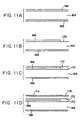
- FIG. 11 shows the method of generating the VIPA.
- a parallel plates 164 are made of glass, and have excellent parallelism.
- Reflecting films 166 and 168 are provided on both surfaces of the parallel plates 164 in the vacuum evaporation method, ion beam assist evaporation method, spattering method, etc. It is desired that one of the reflecting films 166 and 168 has the reflectance of 100%, and the other has the reflectance higher than 80% and lower than 100%.
- one of the reflecting films 166 and 168 is partly ground to form a radiation window 170.
- the reflecting film 166 shown in FIG. 11B is ground such that the radiation window 170 can be formed on the same surface as the reflecting film 166 on the parallel plates 164.
- the reflecting film 168 can be partly ground such that the radiation window can be formed on the same surface as the reflecting film 168 on the parallel plates 164.
- the radiation window can be provided in either sides of the parallel plates 164.
- the reflecting film can be ground in the etching process, but also can be processed in a mechanical carving process which requires smaller cost.
- the parallel plates 164 are to be carefully processed to minimize the damage to the parallel plates 164. For example, when there is large damage to the parallel plates 164 forming a radiation window, the parallel plates 164 suffer excess losses by the dispersion of received input rays.
- a portion of the parallel plates 164 is masked corresponding to a radiation window so that the portion cannot be covered with the reflecting film.
- a transparent adhesive 172 is applied to the reflecting film 166 and a part of the parallel plates 164 excluding the reflecting film 166. Since the transparent adhesive 172 is also provided in a part of the parallel plates 164, the optical loss can be minimized.
- a protective transparent plate 174 is placed on and protects the reflecting film 166 and reflecting film 166 coated with the transparent adhesive 172.
- the protective transparent plate 174 is placed on the top surface of the parallel plates 164 so that the transparent adhesive 172 can be applied to fill the concave portion after removing the reflecting film 166.
- the adhesive (not shown in the attached drawings) is applied on the top surface of the reflecting film 168 to provide a protective plate (not shown in the attached drawings).
- a protective plate (not shown in the attached drawings).
- an anti-reflection film 176 can be applied to the transparent protective plate 174.
- the protective transparent plate 174 and the radiation window 170 can be covered with the anti-reflection film 176.
- the focal line is assumed to be on the radiation window, or on the opposite surface of the parallel plates into which input rays are input, but the focal line can also be in the parallel plates or before the radiation window.
- two reflecting films reflect the rays between them, and the reflectance of one of them is about 100%.
- the similar effect can be obtained by two reflecting films having the reflectance up to 100%.
- the two reflecting films can have the reflectance of 95%.
- each reflecting film transmits rays and generates interference.
- the luminous flux traveling in different directions depending on the wavelength can be formed on both sides of the parallel plates having reflecting films.
- various reflectance can be changed depending on the characteristic requested by the VIPA.
- the VIPA according to the above mentioned arrangement maintains a constant phase difference between interference rays using multiple reflection. As a result, the characteristic of the VIPA becomes stable, thereby reducing a change in optical characteristic generated by polarization.
- the luminous flux spatially discriminated from each other can be obtained.
- the 'to be spatially discriminated' means that flux can be spatially discriminated.
- various types of luminous flux can be assumed that they can be spatially discriminated when they are parallel and travel in different directions, or are collected in different positions.
- FIG. 12 shows the conventional device in which the VIPA, not diffraction grating, is used as an angular dispersion unit to generate wavelength dispersion.
- a VIPA 240 comprises a first surface 242 having reflectance of about 100%, and a second surface 244 having reflectance of about 98%.
- the VIPA 240 also comprises a radiation window.
- the VIPA 240 is not limited to this configuration, but can have a number of different configurations.
- a ray is output from a fiber 246, collimated by a collimating lens 248, and linearly collected by a cylindrical lens 250 on the VIPA 240 through a radiation window 247. Then, the VIPA 240 generates a collimated ray 251 collected on a mirror 254 by a focal lens 252.
- the mirror 254 can be a mirror portion 256 formed on a substrate 258.
- the mirror 254 reflects rays, and transmits the rays to the VIPA 240 through the focal lens 252. Then, the rays produce multiple reflection in the VIPA 240, and output from the radiation window 247. The rays output from the radiation window 247 are received by the fiber 246 through the collimating lens 248.
- the rays are output from the VIPA 240, reflected by the mirror 254, and returned to the VIPA 240.
- the rays reflected by the mirror 254 are returned through the path they have traveled.
- the different wavelength components of rays have focal points on the different points of the mirror 254, and the rays are reflected and returned to the VIPA 240.
- the different wavelengths travel different distances, and generates wavelength dispersion.
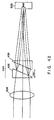
- FIG. 13 shows further in detail the principle of the operation of the VIPA 1 shown in FIG. 12.
- the VIPA 240 forms a virtual image 260 of a beam waist 262, and the virtual image 260 emits rays of light.
- the focal lens 252 collects the focal points of different wavelength components of the collimated rays from the VIPA 240 on the different points of the mirror 254. Furthermore, a longer wavelength 264 is collected on a point 272, a central wavelength 266 is collected on a point 270, and a shorter wavelength 268 is collected on a point 274. The longer wavelength 264 is returned to the virtual image 260 closer to the beam waist 262 than the central wavelength 266. The shorter wavelength 268 is returned to the virtual image 260 farther to the beam waist 262 than the central wavelength 266. In the above mentioned array, normal dispersion takes place.
- the mirror 254 reflects only the rays of a specific interference order, and the rays of other interference orders are collected outside the mirror 254. Furthermore, as described above, the VIPA 1 outputs collimated rays.
- the collimated rays travels in the direction having a difference of m ⁇ in the path from each virtual image where m indicates an integer.
- the m-th interference is defined as an output ray corresponding to m.
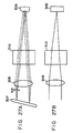
- FIG. 14 shows various interference order of the VIPA.
- the VIPA 1 such as the VIPA 240 emits collimated rays 276, 278, and 280.
- Each of the collimated rays 276, 278, and 280 corresponds to a different interference order. Therefore, for example, the collimated ray 276 corresponds to the ray of the (n + 2)th interference order, the collimated ray 278 corresponds to the ray of the (n + 1)th interference order, and the collimated ray 280 corresponds to the ray of the n-th interference order.
- n indicates an integer.
- the collimated ray 276 is shown as having a plurality of wavelength components 276a, 276b, and 276c.
- the collimated ray 276 is shown as having a plurality of wavelength components 280a, 280b, and 280c.
- the wavelength components 276a, 278a, and 280a are the same wavelengths.
- the wavelength components 276b, 278b, and 280b also have the same wavelengths.
- FIG. 14 shows only the collimated rays of three different interference orders, but the collimated rays of other interference orders are emitted.
- the mirror 254 can reflects only the rays of a single interference order, and return the reflected rays to the VIPA 240.
- the length of the reflecting portion of the mirror 254 is set relatively small, and only the ray corresponding to a single interference order is reflected.
- only the collimated ray 278 is reflected by the mirror 254.
- the collimated rays 278 and 280 are collected outside the mirror 254.
- a wavelength division-multiplexed ray normally contains a number of channels.
- the thickness t between the first surface 242 and the second surface 244 of the VIPA 240 is set to a specified value, the dispersion at each channel with the configuration is simultaneously compensated for.
- each channel has a central wavelength.
- the central wavelengths are normally apart from each other at predetermined frequency intervals.
- the thickness t between the first surface 242 and the second surface 244 is set such that all wavelength components corresponding to the central wavelengths can be output at the same output angle from the VIPA 240. This is possible when the thickness t is set for each channel such that the forward-and-backward traveling distance of the rays on the VIPA 240 can be a multiple of central wavelengths of each channel.
- the value of the thickness t is hereinafter referred to as a 'thickness in the range of a WDM matching free spectrum' or a 'thickness of a WDM matching FSR'.
- the forward-and-backward optical traveling distance (2ntcos ⁇ ) through the VIPA 240 is equal to a value obtained by multiplying a central wavelength of each channel for a different integer having the same ⁇ by an integer.
- n indicates the refractive index of the material between the first surface 242 and the second surface 244, and ⁇ indicates the direction of propagation of luminous flux corresponding to the central wavelength of each channel.
- ⁇ indicates a slope angle of the optical axis of an input ray (refer to FIG. 7).
- the VIPA 240 can simultaneously compensate for the dispersion for all channels of a wavelength division-multiplexed ray.
- the VIPA 240 and the focal lens 252 can (a) concentrate the wavelength component corresponding to the central wavelength of each channel on the point 270 of the mirror 254, (b) concentrate the wavelength component corresponding to a component having a longer wavelength of each channel on the point 272 of the mirror 254, and (c) concentrate the wavelength component corresponding to a component having a shorter wavelength of each channel on the point 274 of the mirror 254. Therefore, using the VIPA 240, the wavelength dispersion can be compensated for all channels of the wavelength division-multiplexed rays.
- FIG. 15 is a graph indicating the amount of dispersion of some channels of the wavelength division-multiplexed ray when the thickness t is set as the thickness of the FSR of the WDM matching.
- the same dispersion takes place for all channels. However, the dispersion should not continue among channels. Furthermore, the range of the wavelength of each channel for which the VIPA 240 compensates for the dispersion can be set by appropriately setting the size of the mirror 254.
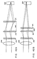
- FIGS. 16A and 16B are side views of the device in which the VIPA is used to assign each value of the wavelength dispersion to a ray of light to explain that the wavelength dispersion depends on the shape of a mirror.
- FIGS. 16A and 16B are similar to FIG. 13 in that they show the directions of the longer wavelength 264, the central wavelength 266, and the shorter wavelength 268 emitted by the virtual image 260 of the beam waist 262.
- the mirror 254 is a convex mirror. Using a convex mirror, the beam shift is extended. Therefore, large chromatic dispersion takes place with a short focal distance and at short intervals.
- the convexity can be viewed only from the side as shown in FIG. 16A, but cannot be viewed from above.
- the mirror 254 is a concave mirror. Using a concave mirror, the sign of the dispersion is inverted. Therefore, abnormal dispersion takes place with a short focal distance and at short intervals.
- the concavity can be viewed only from the side, but cannot be viewed from above as shown in FIG. 16B.
- the mirror 254 normally appears flat from above. However, if the mirror 254 is rotated and viewed from above, it proves that the mirror is a one-dimensional mirror.
- the mirror 254 is located at or near the focal point of the focal lens 252.
- the mirror 254 can be concave or convex when viewed from the side as shown in FIGS. 16A and 16B.
- a convex mirror promotes the wavelength dispersion, and a concave mirror reduces the wavelength dispersion or inverts the negative (normal) into the positive (abnormal).
- the convex mirror generates large dispersion in the negative direction, and the concave mirror either generates small dispersion in the negative direction or inverts the dispersion into positive. This is realized by the level of the chromatic dispersion equal to the function of the curvature of the mirror viewed from the side.
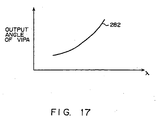
- FIG. 17 is a graph of the output angle of the luminous flux from the VIPA 240 to the wavelength of the luminous flux.
- the change of the wavelength to an output angle is not linear.
- the wavelength dispersion is not constant in a wavelength band as far as a flat mirror, a normal convex mirror, or a normal concave mirror is used as the mirror 254
- the nonlinearity in the wavelength dispersion is defined as higher order dispersion.
- the nonlinearity in the wavelength dispersion can be understood by the following equation (3).
- angular dispersion ⁇ 1 - f ⁇ 1 / R ⁇ wavelength dispersion where f indicates the focal distance of the focal lens 252, and R indicates the radius of the curvature of the mirror 254.
- FIG. 18 is a graph showing the angular dispersion of the VIPA 240 for the wavelength of luminous flux.
- a curve 284 shown in FIG. 18 indicates the slope of a curve 282 shown in FIG. 17.
- the angular dispersion is not constant. Instead, the angular dispersion changes with a wavelength.
- FIG. 19 is a graph showing a part of (1 - f ⁇ (1 / R)) of the equation (3) against a wavelength.
- a straight line 286 is a graph of (1 - f ⁇ (1 / R)) for the wavelength when a flat mirror is used (the radius of the curvature is ⁇ (infinite)).
- a straight line 288 is a graph of (1 - f ⁇ (1 / R)) for the wavelength when a concave mirror is used (the radius of the curvature is '+').
- a straight line 290 is a graph of (1 - f ⁇ (1 / R)) for the wavelength when a convex mirror is used (the radius of the curvature is '-'). As shown in FIG. 19, each mirror has a constant curvature radius.
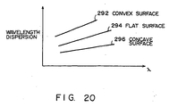
- FIG. 20 is a graph of the wavelength dispersion of the wavelength of the device as shown in FIGS. 16A and 16B.
- the mirror 254 is a common spherical convex mirror, a flat mirror, and a spherical concave mirror.
- a curve 292 indicates the wavelength dispersion for the wavelength when the mirror 254 is a convex mirror.
- a curve 294 indicates the wavelength dispersion for the wavelength when the mirror 254 is a flat mirror.
- a curve 296 indicates the wavelength dispersion for the wavelength when the mirror 254 is a concave mirror.
- the curves 292, 294, and 296 show the products of the angular dispersion shown in FIG. 28 and the straight lines shown in FIG. 19.
- the curve 294 shows the product of the curve 284 shown in FIG. 18 and the straight line 286 shown in FIG. 19.
- the curve 296 shows the product of the curve 284 shown in FIG. 18 and the straight line 288 shown in FIG. 19.
- the wavelength dispersion is not constant although a common spherical convex mirror, flat mirror, or spherical concave mirror is used as the mirror 256.
- the above mentioned wavelength-dependency of the wavelength can be reduced or removed by chirping the curvature of the mirror 254.
- FIG. 21 is a graph of a curve 298 of the equation 3, that is, (1 - f ⁇ (1 / R)), for the wavelength.
- the curve 298 shown in FIG. 21 is obtained by inverting the curve 284 shown in FIG. 18. Therefore, as indicated by a curve 300 shown in FIG. 22, a mirror having the characteristics shown in FIG. 21 generates constant wavelength dispersion.
- FIG. 23 shows an example of the shape (section) of a dispersion mirror satisfying the equation 3 and having a wavelength dispersion value of -2500 ps/nm.
- the shape of the mirror is non-spherical.
- the VIPA 1 and the mirror are spatially arranged such that the angular dispersion can be parallel to the section.
- the shape of the mirror can have the same shape in the direction vertical to the section (that is, a cylindrical shape).
- rays have a focal point defined by a lens in the direction vertical to the section regardless of the wavelength, it is not necessary to set a long distance in the direction vertical to the section.
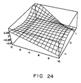
- the shape of the non-spherical mirror is set as a three-dimensional non-spherical mirror which gradually changes it shape in the direction vertical to the section, that is, in the direction vertical to the angular dispersion direction of the VIPA.
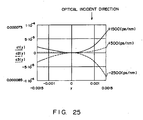
- the section has the shape as shown in FIG. 25 in the position of the dispersion value of -500 ps/nm and +1500 ps/nm.
- the dispersion value changing from negative to positive
- the shape changes from the non-spherical convex surface to the non-spherical concave surface.
- the dispersion value is 0, the section is substantially flat.
- the wavelength dispersion depends on the position of the rays on the three-dimensional non-spherical mirror after the rays are output with the angular dispersion from the VIPA.
- the process is to be performed on metal such as Al, brass, etc. with a precision three-dimensional processor having a diamond bite and a precision movable stage. Since a mirror ground by the above mentioned processor is normally expensive, it is recommended that a metal mold having an inverted shape of a necessary shape is processed, an appropriate transferring and forming process is performed on plastic, glass having a low melting point, solgel glass, etc. using the metal mold, and a mirror is finally formed by applying metal such as Au, Al, etc., or a dielectric multilayer film. In addition, such a three-dimensional shape can be obtained using ion beam etching and resists having different thicknesses.
- the moving unit can be configured mainly by, for example, a linear slider, a motor, etc.
- the components are not limited to them. That is, the linear slider can be replaced with a tremor stand, etc., and the motor can be replaced with an actuator, etc.
- the wavelength dispersion and a wavelength dispersion slope can be varied independent of each other.
- FIG. 26 shows the configuration in which the wavelength dispersion and a wavelength dispersion slope can be varied independent of each other.
- a unit for generating a parallel shift of an optical path by each wavelength, and a unit for varying the amount of the shift of the optical path are provided.
- an optical path is shifted in parallel by a wavelength in the direction vertical to the angular dispersion direction of the VIPA, that is, in the moving direction of the mirror. Therefore, the wavelength dispersion can be varied by a wavelength, that is, a wavelength dispersion slope can be generated.
- a change in given wavelength dispersion is limited. Therefore, it is only necessary to invert the direction of the shift of an optical path by a wavelength to change the positive or negative state of a wavelength dispersion slope.
- Described below are some examples of a practical unit for shifting an optical path in parallel by each wavelength in the direction vertical to the angular dispersion direction of the VIPA, and a practical unit for varying the amount of the shift of the optical path.
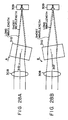
- FIGS. 27 and 28 show the embodiments based on the above mentioned principle.
- FIG. 27A As shown in FIG. 27A, as viewed from the side, the output rays from the VIPA 307 are emitted in different directions depending on the wavelengths, collected on a lens 308, and received by a three-dimensional mirror 309 through parallel plates 310. Then, the rays are received on the different points of the three-dimensional mirror 309 depending on the wavelength. Therefore, different wavelength dispersion takes place depending on the wavelength, thereby performing dispersion compensation.
- FIG. 27B is a view from the angular dispersion direction. In this view, the rays having different wavelengths are dispersed in the direction vertical to the drawings.
- the parallel plates 310 is inserted between the lens 308 and the three-dimensional mirror 309.
- the parallel plates are made of transparent materials having relatively large refractive index wavelength dispersion in an available wavelength band. Practically, it is, for example, polycrystal Si. Otherwise, it can be Ge, GaAs, etc.
- anti-reflection films of multilayer dielectric films are applied.
- the parallel plates 310 are set at an angle 313 with the output ray from the pseudo middle processing unit 8 in the direction vertical to an angular dispersion direction 312 of the VIPA 307 as shown in FIG. 28A, then the angle of the refraction of the rays depends on the refractive index of each wavelength based on the Snell's law. As a result, an optical path shift 314 is caused in parallel depending on each wavelength in the direction vertical to the angular dispersion direction 312 of the VIPA 307. With the optical path shift, the point at which a ray is received on the three-dimensional mirror 309 depending on each wavelength can be controlled independent of the angular dispersion of the VIPA 307.
- the ray having each wavelength angular-dispersed by the VIPA 307 is led to the three-dimensional mirror 309, and the reflected ray is introduced to the VIPA 307 again. Accordingly, in addition to the functions of the above mentioned embodiment in which a predetermined amount of dispersion can be caused to the entire wavelength by leading a ray of each wavelength angular-dispersed by the VIPA 307 to the three-dimensional mirror 309 and inputting a reflected light to the VIPA 307 again, the amount of dispersion to each wavelength can be independently controlled by shifting the ray in the direction vertical to the angular dispersion direction of the VIPA 307, and leading the ray to the three-dimensional mirror 309.
- the wavelength dispersion slope can be controlled independent of the amount of wavelength dispersion.
- n ⁇ 1 ⁇ sin ⁇ ⁇ 1 n ⁇ 2 ⁇ sin ⁇ ⁇ 2
- n1 indicates the refractive index of an input medium
- ⁇ 1 indicates an incident angle
- n2 indicates the refractive index of the output medium
- ⁇ 2 indicates an output angle.
- the amount of the optical path shift 314 can be varied.
- the amount of the optical path shift 314 is varied, and the wavelength dispersion slope can be changed.
- the optical path is simultaneously and entirely changed, and the wavelength dispersion is also changed. Therefore, it is necessary to move the three-dimensional mirror 309 such that the appropriate wavelength dispersion can take place.
- the angle and the position of the mirror have to be simultaneously changed.
- the angle can be changed by, for example, the rotation of a motor, etc.
- the changing method is not limited to this.
- the direction of the optical path shift by a wavelength depends on whether the angle is changed in the direction A or B, thereby inverting the positive and negative state of the wavelength dispersion slope.
- the number of the parallel plates is not limited to one value. That is, there may be plural sets of parallel plates.
- Si, etc. used in the present embodiment has the temperature characteristic of the refractive index of 1.5 x 10 -4 (/°C), which is a large value, it may cause a change in the optical path shift depending on the temperature.
- the problem can be solved by further comprising a control device for controlling the temperature of the parallel plates.
- the control device for controlling the temperature comprises at least a temperature sensor such as a platinum resistance, a thermistor, etc., and a heating/cooling device such as a heater and a Peltier device, and controls the heating/cooling device such that the value of the temperature obtained from the temperature sensor can be maintained at a constant level.
- a temperature sensor such as a platinum resistance, a thermistor, etc.
- a heating/cooling device such as a heater and a Peltier device
- the refractive indices of Si are respectively 3.47958 and 3.47666, and the difference between the refractive indices is as small as 0.003. Therefore, for example, when the thickness of an Si plate is 50 mm with an angle of 40°, the amount of the optical path shift is up to 8 ⁇ m. Therefore, although the above mentioned three-dimensional non-spherical mirror largely changes by 2,000 ps/nm per mm, only the amount of change of the wavelength dispersion up to 12 ps/nm can be made.
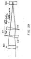
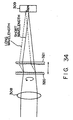
- FIG. 29 shows an embodiment of the present invention.
- At least one prism pair 317 configured by arranging two prisms 315 and 316 made of a transparent material having a large refractive index wavelength dispersion in parallel to each other and symmetrically about a point is inserted between the lens 308 and the three-dimensional mirror 309.
- the prisms 315 and 316 are made of a transparent material having a relatively large refractive index wavelength dispersion in an available wavelength band. Practically, they are made of polycrystal Si. Otherwise, they can be Ge, GaAs, etc.
- anti-reflection films of dielectric multilayer films are applied.
- the rays refracted by the first prism 315 is refracted by the same amount in the opposite direction by the second prism 316 which is arranged in parallel and in the point-symmetrical position with the first prism 315.
- the rays travel in the same direction after passing through the prism pair 317. If the rays travel in the direction vertical to the angular dispersion direction of the VIPA, the rays reflected by the three-dimensional mirror 309 are returned through the similar optical path, thereby causing no losses.
- the angle of the ray refracted by the prisms 315 and 316 depends on the prism angles and the refractive indices of the prisms 315 and 316.
- each wavelength has its own refractive index. Therefore, the refractive angle of a ray having each wavelength depends on the first prism 315, and the ray is refracted by the same degree in the opposite direction. As a result, an optical path shift 319 is generated in parallel by each wavelength in the direction vertical to the angular dispersion direction of the VIPA.
- the optical path shift 319 can be varied, and the wavelength dispersion slope can be changed.
- the optical path is simultaneously and entirely changed, and the wavelength dispersion is also changed. Therefore, it is necessary to move the three-dimensional mirror 309 such that the appropriate wavelength dispersion can take place.
- the space 318 of the prism pair 317 and the position of the mirror have to be simultaneously changed.
- the space in the prism pair 317 can be changed by, for example, using various units as well as the above mentioned mirror moving unit, etc. The changing method is not limited to this.
- the direction in which an optical path shift is generated by a wavelength can be inverted to change the positive/negative state of the slope (wavelength dispersion slope) of the wavelength dispersion.
- the method of rotating the prism pair 317 is, but is not limited, to use, for example, a motor.
- Si, etc. used in the present embodiment has the temperature characteristic of the refractive index of 1.5 x 10 -4 (/°C), which is a large value, it may cause a change in the optical path shift by the change of a refractive index depending on the temperature.
- the problem can be solved by further comprising a control device for controlling the temperature of the prisms.
- the control device for controlling the temperature comprises at least a temperature, sensor such as a platinum resistance, a thermistor, etc., and a heating/cooling device such as a heater and a Peltier device, and controls the heating/cooling device such that the value of the temperature obtained from the temperature sensor can be maintained at a constant level.
- the refractive indices of Si are respectively 3.47958 and 3.47666, and the difference between the refractive indices is as small as 0.003. Therefore, for example, when the prism angle is 14° and the space in the prism pair is 50 mm, the amount of the optical path shift is up to 12 ⁇ m. Therefore, although the above mentioned three-dimensional non-spherical mirror largely changes by 2,000 ps/nm per mm, only the amount of change of the wavelength dispersion up to 25 ps/nm can be made.
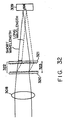
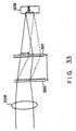
- FIG. 32 shows an embodiment of the present invention.
- At least one diffraction grating pair 322 configured by arranging two diffraction gratings 320 and 321 having angular dispersion in the direction vertical to the angular dispersion direction of the VIPA in parallel and symmetrically about a point with each other is inserted between the lens 308 and the three-dimensional mirror 309.
- a transmitting blazed grating having relatively large angular dispersion in an available wavelength band and having a high primary diffraction efficiency at a predetermined angle in an available wavelength band is used as the diffraction gratings 320 and 321.
- the blazed grating can be obtained by making a master mold by processing glass in a direct ion beam etching method or grinding glass or metal to transfer-form a resin layer on a glass substrate. On both sides of the diffraction gratings 320 and 321, anti-reflection films of dielectric multilayer films are applied.
- the output ray from the lens 308 is diffracted in the direction satisfying the equation (5) by the first diffraction grating 320, thereby curving the optical path.
- the wavelength diffracting at an angle satisfying the Snell's law shown by the equation (6) has the highest diffraction efficiency, and the wavelength is referred to as a blaze wavelength.
- the diffraction gratings 320 and 321 have a blaze angle and a refractive index appropriately selected such that the available wavelength band can substantially match the blaze wavelength.
- the diffracted and curved rays are diffracted and curved again in the opposite direction by equal degrees by the second diffraction grating 321 arranged in the parallel and point symmetric position with the first diffraction grating 320.
- the rays travel in the same direction after passing through the diffraction grating pair 322. If the rays travel in the direction vertical to the angular dispersion direction of the VIPA, the rays reflected by the three-dimensional mirror 309 return through the similar optical path, thereby suffering no losses.
- the diffraction angle depends on the wavelength
- the diffraction angle of a ray of each wavelength depends on the first diffraction grating 320
- the ray is similarly diffracted in the opposite direction by the second diffraction grating 321.
- an optical path shift 324 is generated in parallel according to each wavelength in the direction vertical to the angular dispersion direction of the VIPA.
- the optical path shift 324 can be varied, and the wavelength dispersion slope can be changed.
- the optical path is simultaneously and entirely changed, and the wavelength dispersion is also changed. Therefore, it is necessary to move the three-dimensional mirror 309 such that the appropriate wavelength dispersion can take place.
- the space 323 of the diffraction grating pair 322 and the position of the mirror have to be simultaneously changed.
- the space 323 in the diffraction grating pair 322 can be changed by, for example, using various units as well as the above mentioned mirror moving unit, etc.
- the changing method is not limited to this.
- the method of rotating the diffraction grating pair 322 is, but is not limited, to use, for example, a motor.
- the number of the diffraction grating pairs 322 is not limited to one value, but there can be plural pairs.
- the diffraction angle of a diffraction grating is normally temperature-dependent, and it may cause a change in the optical path shift by the change of a diffraction angle depending on the temperature.
- the control device for controlling the temperature comprises at least a temperature sensor such as a platinum resistance, a thermistor, etc., and a heating/cooling device such as a heater and a Peltier device, and controls the heating/cooling device such that the value of the temperature obtained from the temperature sensor can be maintained at a constant level.
- the blaze wavelength is 1,546 nm, and the diffraction angle is 38.2°.
- the space in the diffraction grating pair is as small as 25 mm, the amount of the optical path shift is up to 720 ⁇ m when the wavelengths are 1,528 nm and 1,563 nm. Therefore, although the above mentioned three-dimensional non-spherical mirror changes by 800 ps/nm per mm, the amount of change of the wavelength dispersion up to 25 ps/nm can be made.
- the amount of the compensation of the dispersion slope corresponds to 290 km with the normal SMF having the wavelength dispersion slope of 0.06 ps/nm2/km, and is a sufficient compensation amount.
- wavelength dispersion slope Described below is another embodiment of a method of changing the positive/negative state of the slope of wavelength dispersion (wavelength dispersion slope).
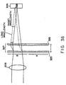
- FIG. 35 shows an embodiment of the present invention.
- At least one of diffraction grating pair 327 configured by two diffraction gratings 325 and 326 arranged parallel and point-symmetric to each other and having angular dispersion in the direction substantially vertical to the angular dispersion direction of the VIPA, and having at least two areas (for example, A and B) showing angular dispersion in opposite directions is used.
- a transmitting blazed grating is used.
- rays are emitted to different areas having angular dispersion in the opposite directions to generate the angular dispersion in the opposite directions and have an optical path shift 328 generated by a wavelength in the opposite direction, thereby changing the positive/negative state of the slope of wavelength dispersion (wavelength dispersion slope).
- the method of moving the diffraction grating pair 327 can be realized by various means as the above mentioned mirror moving unit, and is not limited to a specific method.
- blazed gratings are formed in the opposite directions in the areas A and B.
- Described below is another embodiment of a method of varying wavelength dispersion.
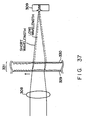
- FIGS. 37 and 38 show other embodiments of the present invention.
- At least one diffraction grating pair 331 configured by two diffraction gratings 329 and 330 arranged parallel and point-symmetric to each other, having angular dispersion in the direction substantially vertical to the angular dispersion direction of the VIPA, and having a plurality of areas having different angular dispersion is used.
- To form a plurality of areas having different angular dispersion on a diffraction grating for example, different blaze angles and numbers of lines are assigned to respective areas.
- the method of moving the diffraction grating pair 331 can be realized by various means as by the above mentioned mirror moving unit, and is not limited to a specific method.
- transmitting blazed grating is used as diffraction gratings, but other diffraction, gratings can be used obviously.
- FIG. 39 shows another embodiment of the present invention.
- a reflecting blazed grating is used as a diffraction grating.
- an output ray from the lens 308 is diffracted in the direction satisfying the equation (7) by the diffraction grating 333, and the optical path is curved.
- the wavelength diffracting at an angle satisfying the reflection law expressed by the equation (8) has the highest diffraction efficiency, and the wavelength is referred to as a blaze wavelength.
- an appropriate blaze angle is selected such that an available wavelength band can substantially match the blaze wavelength.
- the diffracted and curved ray is similarly diffracted and curved again in the opposite direction by the second diffraction grating 334 arranged in the position parallel and point-symmetric with the first diffraction grating 333.
- the rays travel in the same direction after passing through a diffraction grating pair 335. If the rays travel in the direction vertical to the angular dispersion direction of the VIPA, the rays reflected by the three-dimensional mirror 309 are returned through the similar optical path, thereby causing no losses.
- the diffraction angle depends on a wavelength
- a ray having each wavelength has a different diffraction angle depending on the first diffraction grating 333, and the diffraction takes place again in the opposite direction by the second diffraction grating 334.
- an optical path shift 337 takes place by each wavelength in parallel in the direction vertical to the angular dispersion direction of the VIPA.
- optical path shift 337 can be varied by changing a space 336 of the diffraction grating pair 335 by moving one diffraction grating 334 while keeping the parallelism although a reflecting diffraction grating is used.
- a rectangular diffraction grating, a cos curve diffraction grating, an echelon grating, etc. can be used. That is, the type of diffraction grating is not limited to a specific type.
- an output ray for which the wavelength dispersion and a wavelength dispersion slope are compensated can be retrieved by inserting the circulator as shown in FIG. 1 into the tip of the fiber shown in FIG. 4.
- FIG. 40 shows the configuration of solving the problem of the polarized-wave-dependent losses according to the above mentioned embodiment.
- a polarized-wave-dependent loss occurs on the ray output from the lens 8 to a grating pair 342 shown in FIG. 40 after the ray passes through blazed gratings 340 and 341.
- a polarization rotation element 350 is provided. The polarization of a ray reflected by the three-dimensional mirror 309 and returned is orthogonalized by 90° by the polarization rotation element 350 in the returning path.
- the polarization rotation element 350 having the polarization rotating function can be, for example, a ⁇ /4 wavelength plate, a Faraday rotator, etc.
- FIG. 41 shows the configuration of continuously changing until inverting the amount of wavelength dispersion compensation provided for a ray according to an embodiment of the present invention.
- the function of continuously varying from the negative wavelength dispersion slope to the positive wavelength dispersion slope can be realized. That is, after the grating pair 362 provides an offset for the optical paths of rays having different wavelengths, the space 343 in the grating pair 342 is appropriately adjusted, thereby outputting and crossing optical paths of rays having different wavelengths to be received by the three-dimensional mirror 309. When the space 343 is set to another value, the optical paths of the rays having different wavelengths do not cross each other when they are received by the three-dimensional mirror 309.
- the optical path shift of the rays having different wavelengths can be adjusted, and the points on the three-dimensional mirror 309 at which the rays are received can be exchanged.
- the amount of wavelength dispersion provided for each wavelength can be varied, and the amount of wavelength dispersion can be exchanged.
- to control the value of the amount of wavelength dispersion for each wavelength is to change a wavelength dispersion slope.
- FIG. 42 shows an example of a variation of the embodiment shown in FIG. 41.
- a grating 370 shown in FIGS. 42A and 42B, having the functions of gratings 361 and 340 shown in FIGS. 41A and 41B, by assigning an offset to the variable range of a wavelength dispersion slope by, for example, three gratings, the function of continuously varying from the negative wavelength dispersion slope to the positive wavelength dispersion slope can be realized.
- the principle of the operations is the same as in the case shown in FIG. 41.
- the space 343 in the gratings 371 and 370 can be varied, a point 344 on the three-dimensional mirror 309 on which a ray having each wavelength can be varied, and the amount of wavelength dispersion of each wavelength is varied, thereby varying a wavelength dispersion slope.
- FIG. 43 shows another embodiment of the present invention.
- a transmitting echelon grating (or referred to as a grism) is used as a diffraction grating.
- the transmitting echelon grating is a step type diffraction grating, and generates a phase difference by a difference in steps in forward transmission rays. Therefore, forward rays can have the highest diffraction efficiency by setting the condition such that rays having predetermined wavelengths can mutually have the phase difference as expressed by the equation (9).
- the output ray from the lens 308 is diffracted by the first diffraction grating 438 in the direction satisfying the equation (9), and the optical path is curved.
- the step difference is appropriately selected such that the central wavelength of an available wavelength band can corresponds to a forward ray.
- the diffracted and curved ray is also diffracted and curved again by the second diffraction grating 439 arranged in the position parallel and point-symmetric with the first diffraction grating 438 basically as in the case of the blazed grating. Therefore, the rays travel in the same direction after passing through a diffraction grating pair 440. If the rays travel in the direction vertical to the angular dispersion direction of the VIPA, the rays reflected by the three-dimensional mirror 309 returns through the similar optical path, thereby causing no losses.
- the diffraction angle depends on a wavelength
- a ray having each wavelength has a different diffraction angle depending on the first diffraction grating 438, and the diffraction takes place again in the opposite direction by the second diffraction grating 439.
- an optical path shift 442 takes place by each wavelength in parallel in the direction vertical to the angular dispersion direction of the VIPA.
- nt - t ⁇ cos ⁇ + d ⁇ sin ⁇ m ⁇ ⁇
- n indicates a refractive index
- t indicates a step difference
- ⁇ indicates a rotation angle
- d indicates the space in a diffraction grating
- m indicates an order
- ⁇ indicates a wavelength
- an amount of optical path shift 442 can be varied by changing the space 441 in the diffraction grating pair 440 by moving one diffraction grating 439 while maintaining the parallelism.
- the diffraction direction is substantially forward. Therefore, the amount of optical path shift 442 changes by changing the space 441 in the diffraction grating pair 440.
- the amount of optical path shift 442 changes by changing the space 441 in the diffraction grating pair 440.
- the three-dimensional mirror 309 such that the appropriate wavelength dispersion can take place as in the case of the blazed grating.
- such a large diffraction angle may cause the problem that the focal position of the rays on the three-dimensional mirror 309 is shifted in the optical path direction.
- the diffraction direction is substantially forward in the case of the echelon grating, There occurs no problems of a shift of the focal position.
- the wavelengths of intensifying forward rays are 1,546 nm.
- the space in the diffraction grating pair is as small as 25 mm
- the amount of the optical path shift is up to 940 ⁇ m for the wavelengths 1,528 nm and 1,563 nm
- the amount of the change in the wavelength dispersion up to 750 ps/nm can be assigned although the above mentioned three-dimensional non-spherical mirror shows a change of 800 ps/nm per mm.
- This amount of compensation of a dispersion slope corresponds to 360 km for the common SMF having the wavelength dispersion slope of 0.06 ps/nm2/km, which is a sufficient amount of compensation.
- the blazed grating shown in FIGS. 41 and 42 can be replaced with the echelon grating.
- a transmitting blazed grating is used as a diffraction grating.
- other diffraction gratings can also be used.
- the VIPA has a reflecting film for reflecting rays.
- FIG. 7 shows the VIPA 76 having the reflecting surfaces 122 and 124 for reflecting rays.
- the VIPA is not limited to be used with a film for providing a reflecting surface. Instead, the VIPA has to be provided with an appropriate reflecting surface, but it is not limited to a film.
- the VIPA includes a transparent glass plate generating multiple reflection.
- FIG. 7 shows the VIPA 76 provided with the plate 120 having a reflecting surface.
- the VIPA is not limited to a glass material or any type of plate. Instead, the reflecting surfaces have to be isolated from each other by a spacer.
- the reflecting surface of the VIPA can be isolated by air without a glass plate. Therefore, for example, the reflecting surface can be described as being isolated by a transparent material such as an optical glass, air, etc.
- the operation of the VIPA depends on the thickness and the refractive index of the material between the reflecting surfaces of the VIPA. Furthermore, the operation and the wavelength of the VIPA can be correctly adjusted by controlling the temperature of the VIPA.
- the above mentioned embodiment of the present invention can provide an apparatus for generating an arbitrary wavelength dispersion and a wavelength dispersion slope, and simultaneously dispersion-compensating the wavelength dispersion and wavelength dispersion slope actually accumulated in an optical fiber in a multichannel multiwavelength regime. Therefore, according to the embodiments of the present invention, the VIPA is not limited to a specific configuration.
- the VIPA can have a radiation window, and the reflection on each surface of the VIPA is not limited to a specific example.
- An embodiment provides an apparatus for individually controlling the wavelength dispersion and the wavelength dispersion slope, which has not been realized by the conventional technology.
Landscapes
- Physics & Mathematics (AREA)
- General Physics & Mathematics (AREA)
- Optics & Photonics (AREA)
- Chemical & Material Sciences (AREA)
- Dispersion Chemistry (AREA)
- Engineering & Computer Science (AREA)
- Electromagnetism (AREA)
- Computer Networks & Wireless Communication (AREA)
- Signal Processing (AREA)
- Optical Communication System (AREA)
- Optical Filters (AREA)
- Diffracting Gratings Or Hologram Optical Elements (AREA)
- Mechanical Light Control Or Optical Switches (AREA)
Description
- The present invention relates to an apparatus for providing wavelength dispersion for compensating for the wavelength dispersion accumulated in an optical fiber transmission network.
- In the conventional fiber optical communications system for transmitting information through an optical system, a transmitter transmits a pulse to a receiver through an optical fiber. However, the wavelength dispersion of an optical fiber deteriorates the quality of a signal of a system.
- To be more practical, as a result of wavelength dispersion, the transmission speed of a signal of an optical fiber depends on the wavelength of the signal. For example, if a pulse having a long wavelength (for example, the pulse of the wavelength indicating a red color pulse) is transmitted at a higher speed than a pulse having a short wavelength (for example, the pulse of the wavelength indicating a blue color pulse), it is normal dispersion. On the other hand, if a pulse having a short wavelength (for example, the pulse of the wavelength indicating a blue color pulse) is transmitted at a higher speed than a pulse having a long wavelength (for example, the pulse of the wavelength indicating a red color pulse), then it is abnormal dispersion.
- Therefore, when a pulse contains red and blue pulses and is transmitted from a transmitter, the pulse is divided when it is transmitted through an optical fiber into a red pulse and a blue pulse which are received by a photodetector at different times. If a red pulse is transmitted at a higher speed than a blue pulse, it is normal dispersion.
- If there are continuous wavelength components from blue to red as another example of pulse transmission, a pulse is extended in an optical fiber and distorted by wavelength dispersion because a red component and a blue component are transmitted at different speeds. Since all pulses contain finite wavelength extension, such wavelength dispersion frequently occurs in the fiber optical communications system.
- Therefore, it is necessary for the fiber optical communications system to compensate for wavelength dispersion to obtain a higher transmission capacity.
- To compensate for the wavelength dispersion, the fiber optical communications system requires an inverse dispersion device. Normally, an inverse dispersion device provides inverse dispersion for a pulse to nullify the dispersion generated by transmission through an optical fiber.
- There are several devices which can be used as an inverse dispersion device. For example, a dispersion compensation fiber has a specific sectional index profile, thereby functioning as an inverse dispersion device and providing the inverse dispersion for nullifying the dispersion generated by the optical fiber. However, the dispersion compensation fiber is expensive in production cost, and has to be sufficiently long enough to successfully compensate for the wavelength dispersion. For example, when an optical fiber is 100 km long, the dispersion compensation fiber is approximately 20 through 30 km. Therefore, there is the problem of a large loss and size.
- FIG. 1 shows the chirp fiber grating used as an inverse dispersion device to compensate for the chromatic dispersion.
- As shown in FIG. 1, a ray is transmitted through an optical fiber, wavelength-dispersed, and then provided for an
input port 48 of anoptical circulator 50. Theoptical circulator 50 provides the ray for achirp fiber grating 52. Thechirp fiber grating 52 returns the ray to theoptical circulator 50 such that different wavelength components can be reflected by the channel fiber grating at different distances, different wavelength components can travel different distances, and the wavelength dispersion can be compensated for. For example, thechirp fiber grating 52 can be designed such that a long wavelength component can be reflected at a long distance, and travel a longer distance than a short wavelength. Then, theoptical circulator 50 provides the ray reflected to anoutput port 54 from thechirp fiber grating 52. Therefore, thechirp fiber grating 52 can add inverse dispersion to a pulse. - However, the
chirp fiber grating 52 has very narrow band for a reflected pulse. Therefore, a sufficient wavelength band cannot be obtained to compensate for the ray containing a number of wavelengths such as a wavelength division-multiplexed light. A number of chirp fiber gratings can be cascaded for a wavelength division-multiplexed signal. However, the resultant system becomes costly. The chirp fiber grating obtained by incorporating a circulator is appropriate for a single-wavelength fiber optical communications system, etc. - FIGS. 2 and 3 shows the conventional diffraction grating used to generate wavelength dispersion.
- As shown in FIG. 2, a diffraction grating 56 has a
grating surface 58.Parallel rays 60 having different wavelengths are input into thegrating surface 58. The rays are reflected by each stage of thegrating surface 58, and interferes each other. As a result,rays - FIG. 3A shows a spatial grating pair array used as an inverse dispersion device to compensate for wavelength dispersion.
- As shown in FIG. 3A, a
ray 67 is diffracted from a first diffraction grating 68, and becomes aray 69 for a short wavelength and aray 70 for a long wavelength. Theseray 67 andray 70 are diffracted by a second diffraction grating 71, and travel in the same direction. As shown in FIG. 3A, the wavelength components having different wavelengths travel different distances, thereby compensating for the wavelength dispersion. A long wavelength (such as theray 70, etc.) travels a longer distance than a short wavelength. Therefore, the spatial grating pair array shown in FIG. 3A indicates abnormal dispersion. - FIG. 3B shows another spatial grating pair array used as an inverse dispersion device to compensate for chromatic dispersion.
- As shown in FIG. 3B,
lenses 72 and 74 are positioned between the first andsecond diffraction gratings - The spatial grating pair array as shown in FIGS. A and B are normally used to control the dispersion using a laser resonator. However, an actual spatial grating pair array cannot provide sufficient dispersion to compensate for a relatively large amount of chromatic dispersion generated by the fiber optical communications system. To be more practical, the angular dispersion generated by diffraction grating is normally very small, that is, approximately 0.05°/nm. Therefore, to compensate for the wavelength dispersion generated in the fiber optical communications system, the first and second diffraction grating 68 and 71 have to be largely apart. Accordingly, such a spatial grating pair array is not practical at all.
- FIG. 4 shows the conventional technology of an inverse dispersion device using a VIPA.
- In the above mentioned conventional technology, in the patent application numbers 10-534450 and 11-513133, the 'Virtually Imaged Phased Array' as shown in FIG. 4, that is, the device containing the portion referred to as
VIPA 1, is suggested as an inverse dispersion device. The VIPA transmits from the VIPA the rays having different wavelengths spatially discriminated. This device includes anoptical return device 2 for generating multiple reflection in the VIPA. - The above mentioned device can be realized by comprising a device including the
VIPA 1 for receiving the input ray of a wavelength in the range of continuous wavelengths, and continuously generating a corresponding output ray. The output ray can be spatially discriminated from the output ray of a different wavelength in the range of the continuous wavelengths (for example, traveling in different directions). If the output ray can be discriminated at a forward angle, it proves that the device provides angular dispersion. - Furthermore, the above mentioned device is realized by comprising the
VIPA 1 and theoptical return device 2. TheVIPA 1 contains a transmission area and a transparent element. By traveling through the transmission area, a ray can be input from and output to theVIPA 1. A.transparent element 3 has the first and the second surfaces. The second surface is reflective, and passes a part of an input ray. The input ray passes through the transmission area. Then, it is received by theVIPA 1, and is reflected many times between the first and second surfaces of the transparent element. A plurality of the transmitted rays interfere each other, and anoutput ray 4 is generated. The input ray has a wavelength in the range of continuous wavelengths, and the output ray can be spatially discriminated from the ray of another wavelength in the range of the continuous wavelengths. Theoptical return device 2 can return the output ray in the completely opposite direction to the second surface, pass it through the second surface, and input it into theVIPA 1. The output ray is multiple-reflected in theVIPA 1, and output to an input path through the transmission area of theVIPA 1. - Furthermore, the above mentioned device can be realized by comprising a device including a VIPA for generating a plurality of output rays having the same wavelengths as the input ray and having different interference orders. The device also includes an optical return device for returning an output ray at one interference order to the VIPA, and not returning other output rays. Thus, only the ray corresponding to one interference order is returned to the VIPA.
- In addition, the above mentioned device can be realized by including a VIPA, an optical return device, and a
lens 5. The VIPA receives an input ray, and generates a corresponding output ray transmitted from the VIPA. The optical return device receives the output ray from the VIPA, and returns it to the VIPA. The lens is positioned such that: (a) the output ray can be returned from the optical return device to the VIPA by passing through the lens from the VIPA and being collected at the optical return device by the lens; (b) the output ray can be returned from the optical return device to the VIPA by being directed from the optical return device to the lens, and then to the VIPA by the lens; and (c) the output ray from the VIPA to the lens can travel parallel to and in the opposite direction of the output ray returned from the lens to the VIPA. Furthermore, the output ray from the VIPA to the lens does not overlap the output ray returned from the lens to the VIPA. - Furthermore, the above mentioned device can be realized by including the device having a VIPA, a
mirror 6, and a lens. The VIPA receives an input ray, and generates an output ray traveling from a corresponding VIPA. The lens collects the output ray at the mirror, the mirror reflects the output ray, and the reflected ray is returned to the VIPA by the lens. The mirror is formed such that the device can perform constant wavelength dispersion. - As described above, the VIPA has the function of performing angular dispersion as diffraction grating, and can compensate for wavelength dispersion. Especially, it is characterized by large angular dispersion, and easily provides a practical inverse dispersion device. However, it requires specific conditions of a practical inverse dispersion device for use in a wavelength multiplexed transmission system.
- FIG. 5 shows the wavelength dispersion of an optical fiber normally put for practical use.
- The wavelength dispersion of an optical fiber normally put for practical use is not constant by a wavelength as shown in FIG. 5, but normally has a small positive slope (the longer the wavelength, the larger positive value the wavelength dispersion indicates). For example, in a common single mode fiber (SMF), the wavelength dispersion per 1 km is about +17 ps/nm while the wavelength dispersion slope indicates 0.06 ps/nm2. When a required wavelength band width is, for example, 35 nm, the wavelength dispersion changes approximately +2 ps/nm. Such a slope of wavelength dispersion can be referred to as a wavelength dispersion slope or a second order wavelength dispersion. The wavelength dispersion slope is not always positive (the longer the wavelength, the larger the wavelength dispersion), but a wavelength dispersion slope can be generated such that it can be negative in a wavelength extension longer than the zero dispersion wavelength in a dispersion shifted fiber with the zero dispersion wavelength shifted to the wavelength band of 1.5 µm by changing the structure of the fiber.
- Furthermore, the wavelength dispersion graph shown in FIG. 5 is not actually linear, and the slope of wavelength dispersion (wavelength dispersion slope) is not strictly constant, but the third order wavelength dispersion seldom causes problems at a transmission speed of about 40 Gb/s, and can be ignored.
- Considering the actual wavelength dispersion of the transmission line of an optical fiber, the wavelength dispersion and a wavelength dispersion slope per unit length depend on the type of optical fiber as shown in FIG. 5, and the actual wavelength dispersion and wavelength dispersion slope depend on the length (transmission distance) of an optical fiber. If the wavelength dispersion of the actual optical fiber transmission line is compensated for by an inverse dispersion device, it is desired that a wavelength dispersion can be somewhat variable because the type and the transmission distance of an optical fiber largely depend on the period in which the optical fiber is installed and the situation of the site of the installed optical fiber.
- In the wavelength multiplexed transmission, the compensation of the wavelength dispersion only is not sufficient, but a wavelength dispersion slope becomes a problem. Although the dispersion can be compensated for the wavelength of a signal channel, the wavelength dispersion cannot be completely compensated for with different wavelengths of signal channels if the wavelength dispersion of an inverse dispersion component is constant. Therefore, it is desired that the inverse dispersion device for the wavelength multiplexed transmission has a wavelength dispersion slope. Furthermore, since there are various transmission distances as described above, the wavelength dispersion slope changes in proportion to the length with the wavelength dispersion, it is also desired that the wavelength dispersion slope is somewhat variable. Furthermore, the value of a wavelength dispersion slope to be provided does not depend simply on the value of the wavelength dispersion because, if the type of optical fiber changes, not only the wavelength dispersion but also the wavelength dispersion slope changes as clearly shown in FIG. 5. That is, in the wavelength multiplexed transmission, it is the most desirable that the wavelength dispersion and the wavelength dispersion slope can be independently variable when the wavelength dispersion of an optical fiber transmission line is compensated for by an inverse dispersion device.
- The method for having the wavelength dispersion and the wavelength dispersion slope independently vary is not clearly described by the above mentioned patent application numbers 10-534450 and 11-513133. Furthermore, it is not realized by the conventional inverse dispersion devices.
- First, with a dispersion compensation fiber, an index profile including an inverse dispersion slope can be designed. However, changing its value requires various index profiles and lengths, and is not a practical operation. In addition, as described above, there is the problem that the method is costly, has a large loss, and large in size.
- Furthermore, the chirp fiber grating also requires various index profiles and lengths although it can provide an inverse dispersion slope by optimizing the design of the chirp of the chirp fiber grating. Therefore, it is not a practical method, either. Although the wavelength dispersion and the wavelength dispersion slope are changed by changing the temperature, the value of the wavelength dispersion slope simply depends on the value of the wavelength dispersion. As a result, the wavelength dispersion and the wavelength dispersion slope cannot be independently varied. In addition, a sufficient wavelength band to compensate for the ray containing a large number of wavelengths such as a wavelength division-multiplexed ray cannot be obtained.
- In the conventional diffraction grating, it is possible to independently vary the wavelength dispersion and the wavelength dispersion slope to a certain extent by appropriately arranging the diffraction grating. However, as described above, sufficiently large dispersion cannot be realized to compensate for a relatively large amount of chromatic dispersion generated in the fiber optical communications system in a practical size. Therefore, a practical method cannot be realized.
-
WO-A-01/50177 -
WO-A-99/09448 - According to the present invention, there is provided an apparatus for providing wavelength dispersion to different wavelengths of light in a ray comprising multiple wavelengths as set out in
Claim 1. - Optional features are set out in the other claims.
- An embodiment of the invention provides an apparatus for generating arbitrary wavelength dispersion and wavelength dispersion slope, and simultaneously performing dispersion compensation in multiple wavelength range of multiple channels on the wavelength dispersion and wavelength dispersion slope practically accumulated in an optical fiber.
- According to an embodiment, wavelength dispersion and a wavelength dispersion slope can be independently controlled, and can be provided for an optical signal. Therefore, an effective wavelength dispersion compensator can be provided when high-speed optical communications are realized using an optical fiber.
-
- FIG. 1 shows the chirp grating for use as a counter-dispersion unit for compensating for chromatic dispersion;
- FIG. 2 shows the conventional diffraction grating;
- FIG. 3A shows a spatial grating pair array generating abnormal dispersion;
- FIG. 3B shows a spatial grating pair array generating normal dispersion;
- FIG. 4 shows the apparatus for generating wavelength dispersion using a VIPA;
- FIG. 5 shows wavelength dispersion and a wavelength dispersion slope depending on the type of fiber;
- FIG. 6 shows the VIPA;
- FIG. 7 shows in detail the VIPA shown in FIG. 6;
- FIG. 8 shows a cross-sectional view along the line IX - IX of the
VIPA 1 shown in FIG. 6; - FIG. 9 shows the interference between the reflected rays by the VIPA;
- FIG. 10 shows a cross-sectional view along the line IX - IX of the
VIPA 1 shown in FIG. 6 to determine the slope angle of an input ray; - FIGS. 11A, 11B, 11C, and 11D show the method of producing the VIPA;
- FIG. 12 shows the apparatus which uses the VIPA as an angular dispersion unit for generating chromatic dispersion;
- FIG. 13 shows in detail the operation of the apparatus shown in FIG. 12;
- FIG. 14 shows various orders of the interference of the VIPA;
- FIG. 15 shows the chromatic dispersion of several channels of a wavelength division-multiplexed ray;
- FIGS. 16A and 16B are side views of the apparatus which uses the VIPA to disperse a ray;
- FIG. 17 shows the angle of output luminous flux of the VIPA for the wavelength of luminous flux;
- FIG. 18 shows angular dispersion of the VIPA for the wavelength of luminous flux;
- FIG. 19 shows the effects of different mirror types of the apparatus which uses the VIPA;
- FIG. 20 shows the chromatic dispersion for a wavelength of the apparatus which uses the VIPA for each of different mirror types;
- FIG. 21 shows the effect of the mirror of the apparatus which uses the
VIPA 1; - FIG. 22 shows constant chromatic dispersion of the apparatus which uses the
VIPA 1; - FIG. 23 is a sectional view of a mirror for the apparatus which uses the
VIPA 1; - FIG. 24 shows the three-dimensional form of a mirror of the apparatus which uses the
VIPA 1; - FIG. 25 is a sectional view of the mirror of the apparatus which uses the
VIPA 1; - FIG. 26 shows the configuration showing the principle for independently varying the wavelength dispersion and the wavelength dispersion slope;
- FIGS. 27A is a side view of a part of the apparatus for independently varying the wavelength dispersion and the wavelength dispersion slope according to an embodiment of the present invention;
- FIGS. 27 is a top view of a part of the apparatus for independently varying the wavelength dispersion and the wavelength dispersion slope according to an embodiment of the present invention;
- FIGS. 28A and 28B are top views of a part of the apparatus for independently varying the wavelength dispersion and the wavelength dispersion slope according to an embodiment of the present invention;
- FIG. 29 is a top view of a part of the apparatus for independently varying the wavelength dispersion and the wavelength dispersion slope according to an embodiment of the present invention;
- FIG. 30 is a top view of a part of the apparatus for independently varying the wavelength dispersion and the wavelength dispersion slope according to an embodiment of the present invention;
- FIG. 31 is a top view of a part of the apparatus for independently varying the wavelength dispersion and the wavelength dispersion slope according to an embodiment of the present invention;
- FIG. 32 is a top view of a part of the apparatus for independently varying the wavelength dispersion and the wavelength dispersion slope according to an embodiment of the present invention;
- FIG. 33 is a top view of a part of the apparatus for independently varying the wavelength dispersion and the wavelength dispersion slope according to an embodiment of the present invention;
- FIG. 34 is a top view of a part of the apparatus for independently varying the wavelength dispersion and the wavelength dispersion slope according to an embodiment of the present invention;
- FIG. 35 is a top view of a part of the apparatus for independently varying the wavelength dispersion and the wavelength dispersion slope according to an embodiment of the present invention ;
- FIG. 36 is a top view of a part of the apparatus for independently varying the wavelength dispersion and the wavelength dispersion slope according to an embodiment of the present invention;
- FIG. 37 is a top view of a part of the apparatus for independently varying the wavelength dispersion and the wavelength dispersion slope according to an embodiment of the present invention;
- FIG. 38 is a top view of a part of the apparatus for independently varying the wavelength dispersion and the wavelength dispersion slope according to an embodiment of the present invention;
- FIG. 39 is a top view of a part of the apparatus for independently varying the wavelength dispersion and the wavelength dispersion slope according to an embodiment of the present invention;
- FIG. 40 is a top view of a part of the apparatus for independently varying the wavelength dispersion and the wavelength dispersion slope according to an embodiment of the present invention;
- FIG. 41 is a top view of a part of the apparatus for independently varying the wavelength dispersion and the wavelength dispersion slope according to an embodiment of the present invention;
- FIG. 42 is a top view of a part of the apparatus for independently varying the wavelength dispersion and the wavelength dispersion slope according to an embodiment of the present invention; and
- FIG. 43 is a top view of a part of the apparatus for independently varying the wavelength dispersion and the wavelength dispersion slope according to another embodiment of the present invention.
- In the attached drawings, the same functions are assigned the same reference numerals.
- FIG. 6 shows a virtually imaged phased array (VIPA).
- The words 'virtually imaged phased array' and 'VIPA' can be hereinafter replaced with each other.
- In FIG. 6, it is desired that a
VIPA 76 is a thin glass plate. Aninput ray 77 is collected on aline 78 through alens 80 such as a semicylindrical lens, etc., and theinput ray 77, thereby reaching theVIPA 76. Theline 78 is hereinafter referred to as afocal line 78. Theinput ray 77 is radially transmitted from thefocal line 78, and received by theVIPA 76. Then, theVIPA 76 outputsluminous flux 82 of parallel rays. The output angle of theluminous flux 82 changes with the wavelength of theinput ray 77. For example, when the wavelength of theinput ray 77 is λ1, theVIPA 76 outputs the luminous flux 82a having the wavelength of λ1 in a specified direction. When the wavelength of theinput ray 77 is λ2, theVIPA 76 outputs the luminous flux 82a having the wavelength of λ2 in a specified direction. Therefore, theVIPA 76 generates theluminous flux 82a and 82b which can be spatially discriminated from each other. - FIG. 7 shows in detail the
VIPA 76 for use in an embodiment of the present invention. - In FIG. 7, the
VIPA 76 comprises aplate 120 which is made of, for example, glass, and has reflectingfilms film 122 has a reflectance of 95% or higher, but has to be up to 100%. It is desired that the reflectingfilm 124 has the reflectance of approximately 100%. It is also desired that aradiation window 126 is formed on theplate 120, and has a reflectance of approximately 0%. Theinput ray 77 is collected by thelens 80 on thefocal line 78 through theradiation window 126 such that multiple reflection can be generated between the reflectingfilms focal line 78 is desired to be on theplate 120 to which the reflectingfilm 122 is applied. Thus, thefocal line 78 is desired to be positioned in theplate 120 to which the reflectingfilm 122 is applied. Thus, thefocal line 78 is a line for collecting rays on the reflectingfilm 122 through theradiation window 126. The width of thefocal line 78 collected by thelens 80 is also referred to as a beam waist of theinput ray 77. - Thus, according to the arrangement shown in FIG. 7, the beam waist of the
input ray 77 converges on the farther surface (that is, the surface of the reflecting film 122) of theplate 120. By collecting the beam waist on the farther surface of theplate 120, there can be smaller possibility that the area (for example, an area a shown in FIG. 10 described below in detail) of theradiation window 126 in the surface of theplate 120 covered by theinput ray 77 input through theradiation window 126 overlaps the area (for example, an area b shown in FIG. 10 described below in detail) in the reflectingfilm 124 into which theinput ray 77 is first input when it is first reflected by the reflectingfilm 124. To correctly perform the operations of the VIPA, it is desired that the above mentioned overlapping areas can be avoided. - In FIG. 7. an
optical axis 132 of theinput ray 77 has a small slope angle θ. In the first reflection of the reflectingfilm film 122, and diverges after the beam waist. In addition, 95% of the rays are reflected toward the reflectingfilm 124. After being reflected by the reflectingfilm 124, the rays reach the reflectingfilm 122 with a shift by d. Then, 5% of the rays are transmitted through the reflectingfilm 122. Similarly, as shown in FIG. 7, the rays diverge from avirtual image 134 at the beam waist. Thevirtual image 134 is arranged at predetermined intervals of 2t along the line vertical to theplate 120. In this example, t indicates the thickness of theplate 120. The position of the beam waist relative to thevirtual image 134 is automatically set. It is not necessary to adjust the positions of the images. The rays from thevirtual images 134 interfere with each other, and formparallel rays 136 transmitted in the different directions depending on the wavelengths of the input rays 77. - The intervals of the optical paths are d = 2tSinθ, and the difference between the lengths of the adjacent paths is 2tCosθ. The angular dispersion is proportional to the ratio between the two values, that is, proportional to cotθ. As a result, the VIPA generates considerable angular dispersion.
- As clearly shown in FIG. 7, the term 'virtually imaged phased array' has come from the form of the arrangement of the
virtual image 134. - FIG. 8 shows the cross section along the line IX - IX of the
VIPA 76 shown in FIG. 6. - In FIG. 8, the
plate 120 has the reflectingfilms plate 120. The reflecting surfaces 122 and 124 are typical reflecting films applied to theplate 120. As described above, the reflectance of the reflectingsurface 124 is approximately 100% excluding theradiation window 126. The reflectance of the reflectingsurface 122 is 95% or higher. Therefore, the transmittance of the reflectingsurface 122 is 5% or lower. As a result, 5% or lower of the input rays are transmitted through the reflectingsurface 122, and 95% or higher of them are reflected. Changing the reflectance of the reflectingsurfaces surface 122 is to be lower than 100% to transmit a part of the input rays. - The
radiation window 126 is provided in the reflectingsurface 124. It is desired that theradiation window 126 passes rays, and does not reflect them, or has the lowest possible reflectance. Theradiation window 126 receives and reflects theinput ray 77 on the reflectingsurfaces - FIG. 8 shows the cross section along the straight line IX - IX shown in FIG. 6. Therefore, the
focal line 78 shown in FIG. 6 is expressed by dots in FIG. 8. The input rays 77 are radially transmitted from thefocal line 78. Furthermore, as shown in FIG. 8, thefocal line 78 is provided in the reflectingsurface 122. It is not necessary to provide thefocal line 78 in the reflectingsurface 122, but changing the position of thefocal line 78 causes a small change in the characteristic of theVIPA 76. - As shown in FIG. 8, the
input ray 77 enters theplate 120 through the area A0 of theradiation window 126. The point P0 indicates a point in the area A0. - By the reflectance of the reflecting
surface 122, 95% or higher of -the input rays 77 are reflected by the reflectingsurface 122, and input into the area A1 of the reflectingsurface 124. The point P1 indicates a point in the area A1. After being reflected in the area A1 of the reflectingsurface 124, the input rays 77 reach the reflectingsurface film 122, and a part of the input rays 77 is transmitted through the reflectingsurface 122 as an output ray Out 1 referred to as a Ray R1. - Thus, as shown in FIG. 8, the
input ray 77 is multiple-reflected between the reflectingsurface 122 and the reflectingsurface 124. Each time the ray is reflected by the reflectingsurface 122, a transmitted ray is generated. Therefore, for example, immediately after the input rays 77 are reflected in the areas A2, A3, and A4 of the reflectingsurface 124, they are reflected by the reflectingsurface 122, and output rays Out 2, Out 3, andOut 4 are generated. The point P2 indicates a point in the area A2, the point P3 indicates a point in the area A3, and the point P4 indicates a point in the area A4. The output ray Out 2 is indicated by the ray R2, the output ray Out 3 is indicated by the ray R3, and the output ray Out 4 is indicated by the ray R4. FIG. 8 shows only the output rays Out 0, Out 1, Out 2, Out 3, and Out 4, but there are a large number of rays depending on the intensity of theinput ray 77 and the reflectance of the reflectingsurfaces input ray 77. Therefore, the luminous flux can be referred to as an output ray generated by the interference among the output rays Out 1, Out 2, Out 3, andOut 4. - FIG. 9 shows the interference of reflected rays by the VIPA.
- In FIG. 9, the ray transmitted from the
focal line 78 is reflected by the reflectingsurface 124. As described above, the reflectance of the reflectingsurface 124 is approximately 100%, and basically has the function of a mirror. As a result, it can be assumed that the output ray Out 1 has been emitted from the focal line I1 without the reflectingsurfaces - Therefore, as shown in FIG. 9, the focal line I1 is 2t apart from the
focal line 10, where t indicates the distance between the reflectingsurfaces focal line 12 is placed at a distance of 2t from the focal line I1. Furthermore, an output ray lower in intensity than the output ray immediately before is generated by the subsequent multiple reflection between the reflectingsurfaces output ray Out 1. - As shown in FIG. 9, the output rays from focal lines overlap and interfere with each other. In further detail, since the focal lines I1, I2, I3, and I4 are virtual images of the focal line I0, the output rays Out 0, Out 1, Out 2, Out 3, and Out 4 have equal optical phases on the focal lines I1, I2, I3, and I4. Therefore, the interference generates luminous flux transmitting in different directions depending on the wavelength of the
input ray 77. - The VIPA contains the constructive condition which is the feature of designing a VIPA. By satisfying the constructive condition, luminous flux is generated with the interference of output rays intensifying each other. The constructive condition of the VIPA is expressed by the following equation (1).

where φ indicates the transmission direction viewed from the line vertical to the reflectingsurfaces surface 122 and the reflectingsurface 124, and m indicates an integer. - Furthermore, the input rays 77 radially diverge from the
focal line 78 at a specified angle. Therefore, input rays having equal wavelengths travel in a number of different directions from thefocal line 78, and are reflected by the reflectingsurfaces - FIG. 10 shows the cross section along the straight line IX - IX of the VIPA shown in FIG. 6, and shows the characteristic of the VIPA for determining the angle of incidence or the slope angle.
- In FIG. 10, the
input ray 77 is collected by the cylindrical lens (not shown in the attached drawings, and converge on thefocal line 78. As shown in FIG. 10, theinput ray 77 covers an area having the width of "a" in theradiation window 126. After theinput ray 77 is once reflected by the reflectingsurface 122, it reaches the reflectingsurface 124, and covers the area having the width of "b" in the reflectingsurface 124. Furthermore, as shown in FIG. 10, theinput ray 77 travels along theoptical axis 132 having the slope angle of θ1 corresponding to the line vertical to the reflectingsurface 122. - The slope angle θ1 has to be set to a value such that, after the
input ray 77 is once reflected by the reflectingsurface 122, theinput ray 77 cannot be positioned outside the plate through theradiation window 126. That is, the slope angle θ1 has to be set such that theinput ray 77 can be fetched between the reflectingsurface 122 and the reflectingsurface 124, and cannot be leaked out of theradiation window 126. Therefore, to prevent theinput ray 77 from leaking out of the plate through theradiation window 126, the slope angle θ1 is to be set by the following equation (2).
- FIGS. 6 through 10 show a VIPA for receiving an input ray having various wavelengths in a continuous wavelength range. The VIPA is designed to allow self-interference by the multiple reflection of an input ray, and form an output ray. The output ray can be spatially discriminated from the input ray having a different wavelength in continuous wavelength areas. For example, FIG. 8 shows the
input ray 77 indicating the multiple reflection between the reflectingsurfaces input ray 77. - 'Self-interference' refers to the interference generated among a plurality of rays from the same light source. Therefore, since the output rays Out 0, Out 1, Out 2, Out 3, and
Out 4 are generated from the same light sources (that is, the input ray 77), the interference of the output rays Out 0, Out 1, Out 2, Out 3, and Out 4 is referred to as the self-interference of theinput ray 77. - An input ray can have an arbitrary wavelength in the range of continuous wavelengths. Thus, the input ray is not limited to the wavelength of the value selected from the range of discontinuous values. Furthermore, the output rays generated for the input rays of a specific wavelength in the range of continuous wavelengths are spatially discriminated from the output rays generated when the input rays have different wavelengths in the range of continuous wavelengths.
- Therefore, for example, as shown in FIG. 6, the direction (that is, the 'spatial characteristic') of the
luminous flux 82 becomes different when theinput ray 77 has a different wavelength in the range of continuous wavelengths. - FIG. 11 shows the method of generating the VIPA.
- In FIG. 11A, it is desired that a
parallel plates 164 are made of glass, and have excellent parallelism. Reflectingfilms parallel plates 164 in the vacuum evaporation method, ion beam assist evaporation method, spattering method, etc. It is desired that one of the reflectingfilms - In FIG. 11B, one of the reflecting
films radiation window 170. The reflectingfilm 166 shown in FIG. 11B is ground such that theradiation window 170 can be formed on the same surface as the reflectingfilm 166 on theparallel plates 164. Instead, the reflectingfilm 168 can be partly ground such that the radiation window can be formed on the same surface as the reflectingfilm 168 on theparallel plates 164. The radiation window can be provided in either sides of theparallel plates 164. - The reflecting film can be ground in the etching process, but also can be processed in a mechanical carving process which requires smaller cost. However, when a reflecting film is mechanically carved, the
parallel plates 164 are to be carefully processed to minimize the damage to theparallel plates 164. For example, when there is large damage to theparallel plates 164 forming a radiation window, theparallel plates 164 suffer excess losses by the dispersion of received input rays. - Instead of first forming and carving a reflecting film, a portion of the
parallel plates 164 is masked corresponding to a radiation window so that the portion cannot be covered with the reflecting film. - As shown in FIG. 11C, a
transparent adhesive 172 is applied to the reflectingfilm 166 and a part of theparallel plates 164 excluding the reflectingfilm 166. Since thetransparent adhesive 172 is also provided in a part of theparallel plates 164, the optical loss can be minimized. - In FIG. 11D, a protective
transparent plate 174 is placed on and protects the reflectingfilm 166 and reflectingfilm 166 coated with thetransparent adhesive 172. - The protective
transparent plate 174 is placed on the top surface of theparallel plates 164 so that thetransparent adhesive 172 can be applied to fill the concave portion after removing the reflectingfilm 166. - Similarly, to protect the reflecting
film 168, the adhesive (not shown in the attached drawings) is applied on the top surface of the reflectingfilm 168 to provide a protective plate (not shown in the attached drawings). When the reflectingfilm 168 has the reflectance of about 100%, and there is no radiation window on the surface of the sameparallel plates 164, it is not necessary that the adhesive and the protective plate are transparent. - Furthermore, an
anti-reflection film 176 can be applied to the transparentprotective plate 174. For example, the protectivetransparent plate 174 and theradiation window 170 can be covered with theanti-reflection film 176. - According to the above mentioned arrangement, the focal line is assumed to be on the radiation window, or on the opposite surface of the parallel plates into which input rays are input, but the focal line can also be in the parallel plates or before the radiation window.
- According to the above mentioned arrangement, two reflecting films reflect the rays between them, and the reflectance of one of them is about 100%. However, the similar effect can be obtained by two reflecting films having the reflectance up to 100%. For example, the two reflecting films can have the reflectance of 95%. In this case, each reflecting film transmits rays and generates interference. As a result, the luminous flux traveling in different directions depending on the wavelength can be formed on both sides of the parallel plates having reflecting films. Thus, various reflectance can be changed depending on the characteristic requested by the VIPA.
- The VIPA according to the above mentioned arrangement maintains a constant phase difference between interference rays using multiple reflection. As a result, the characteristic of the VIPA becomes stable, thereby reducing a change in optical characteristic generated by polarization.
- According to the above mentioned arrangement, the luminous flux spatially discriminated from each other can be obtained. The 'to be spatially discriminated' means that flux can be spatially discriminated. For example, various types of luminous flux can be assumed that they can be spatially discriminated when they are parallel and travel in different directions, or are collected in different positions.
- FIG. 12 shows the conventional device in which the VIPA, not diffraction grating, is used as an angular dispersion unit to generate wavelength dispersion.
- In FIG. 12, a
VIPA 240 comprises afirst surface 242 having reflectance of about 100%, and asecond surface 244 having reflectance of about 98%. TheVIPA 240 also comprises a radiation window. TheVIPA 240 is not limited to this configuration, but can have a number of different configurations. - As shown in FIG. 12, a ray is output from a
fiber 246, collimated by a collimating lens 248, and linearly collected by acylindrical lens 250 on theVIPA 240 through aradiation window 247. Then, theVIPA 240 generates acollimated ray 251 collected on amirror 254 by afocal lens 252. Themirror 254 can be amirror portion 256 formed on asubstrate 258. - The
mirror 254 reflects rays, and transmits the rays to theVIPA 240 through thefocal lens 252. Then, the rays produce multiple reflection in theVIPA 240, and output from theradiation window 247. The rays output from theradiation window 247 are received by thefiber 246 through the collimating lens 248. - Therefore, the rays are output from the
VIPA 240, reflected by themirror 254, and returned to theVIPA 240. The rays reflected by themirror 254 are returned through the path they have traveled. As described below in detail, the different wavelength components of rays have focal points on the different points of themirror 254, and the rays are reflected and returned to theVIPA 240. As a result, the different wavelengths travel different distances, and generates wavelength dispersion. - FIG. 13 shows further in detail the principle of the operation of the
VIPA 1 shown in FIG. 12. - It is assumed that rays having various wavelength components are received by the
VIPA 240. As shown in FIG. 13, theVIPA 240 forms avirtual image 260 of abeam waist 262, and thevirtual image 260 emits rays of light. As shown in FIG. 13, thefocal lens 252 collects the focal points of different wavelength components of the collimated rays from theVIPA 240 on the different points of themirror 254. Furthermore, alonger wavelength 264 is collected on apoint 272, acentral wavelength 266 is collected on apoint 270, and ashorter wavelength 268 is collected on apoint 274. Thelonger wavelength 264 is returned to thevirtual image 260 closer to thebeam waist 262 than thecentral wavelength 266. Theshorter wavelength 268 is returned to thevirtual image 260 farther to thebeam waist 262 than thecentral wavelength 266. In the above mentioned array, normal dispersion takes place. - The
mirror 254 reflects only the rays of a specific interference order, and the rays of other interference orders are collected outside themirror 254. Furthermore, as described above, theVIPA 1 outputs collimated rays. The collimated rays travels in the direction having a difference of mλ in the path from each virtual image where m indicates an integer. The m-th interference is defined as an output ray corresponding to m. - For example, FIG. 14 shows various interference order of the VIPA.
- In FIG. 14, the
VIPA 1 such as theVIPA 240 emits collimatedrays rays collimated ray 276 corresponds to the ray of the (n + 2)th interference order, thecollimated ray 278 corresponds to the ray of the (n + 1)th interference order, and thecollimated ray 280 corresponds to the ray of the n-th interference order. In the above mentioned description, n indicates an integer. Thecollimated ray 276 is shown as having a plurality ofwavelength components collimated ray 276 is shown as having a plurality ofwavelength components wavelength components - Since the collimated rays travels in different directions with the same wavelengths for different interference orders, and collected in different positions, the
mirror 254 can reflects only the rays of a single interference order, and return the reflected rays to theVIPA 240. For example, as shown in FIG. 14, the length of the reflecting portion of themirror 254 is set relatively small, and only the ray corresponding to a single interference order is reflected. Furthermore, in FIG. 14, only the collimatedray 278 is reflected by themirror 254. Thus, the collimatedrays mirror 254. - A wavelength division-multiplexed ray normally contains a number of channels. By referring to FIG. 12 again, the thickness t between the
first surface 242 and thesecond surface 244 of theVIPA 240 is set to a specified value, the dispersion at each channel with the configuration is simultaneously compensated for. - Further, in detail, each channel has a central wavelength. The central wavelengths are normally apart from each other at predetermined frequency intervals. The thickness t between the
first surface 242 and thesecond surface 244 is set such that all wavelength components corresponding to the central wavelengths can be output at the same output angle from theVIPA 240. This is possible when the thickness t is set for each channel such that the forward-and-backward traveling distance of the rays on theVIPA 240 can be a multiple of central wavelengths of each channel. The value of the thickness t is hereinafter referred to as a 'thickness in the range of a WDM matching free spectrum' or a 'thickness of a WDM matching FSR'. - In this case, the forward-and-backward optical traveling distance (2ntcosθ) through the
VIPA 240 is equal to a value obtained by multiplying a central wavelength of each channel for a different integer having the same θ by an integer. In the description, n indicates the refractive index of the material between thefirst surface 242 and thesecond surface 244, and θ indicates the direction of propagation of luminous flux corresponding to the central wavelength of each channel. Furthermore, as described above, θ indicates a slope angle of the optical axis of an input ray (refer to FIG. 7). - Therefore, if t is set such that 2ntcosθ is equal to a multiple of the central wavelength at each channel for a different integer having the same θ relative to the wavelength corresponding to the central wavelength at each channel, then all wavelength components for the central wavelengths have the same output angle from the
VIPA 240, and have the same focal position on themirror 254. - For example, if the forward-and-backward physical length (double the thickness of 1 mm of the VIPA 240) is 2 mm, and the refractive index is 1.5, then all wavelengths at 100 GHz intervals satisfy the condition. As a result, the
VIPA 240 can simultaneously compensate for the dispersion for all channels of a wavelength division-multiplexed ray. - Therefore, in FIG. 13, when the thickness t is set as the thickness of the FSR of the WDM matching, the
VIPA 240 and thefocal lens 252 can (a) concentrate the wavelength component corresponding to the central wavelength of each channel on thepoint 270 of themirror 254, (b) concentrate the wavelength component corresponding to a component having a longer wavelength of each channel on thepoint 272 of themirror 254, and (c) concentrate the wavelength component corresponding to a component having a shorter wavelength of each channel on thepoint 274 of themirror 254. Therefore, using theVIPA 240, the wavelength dispersion can be compensated for all channels of the wavelength division-multiplexed rays. - FIG. 15 is a graph indicating the amount of dispersion of some channels of the wavelength division-multiplexed ray when the thickness t is set as the thickness of the FSR of the WDM matching.
- As shown in FIG. 15, the same dispersion takes place for all channels. However, the dispersion should not continue among channels. Furthermore, the range of the wavelength of each channel for which the
VIPA 240 compensates for the dispersion can be set by appropriately setting the size of themirror 254. - FIGS. 16A and 16B are side views of the device in which the VIPA is used to assign each value of the wavelength dispersion to a ray of light to explain that the wavelength dispersion depends on the shape of a mirror.
- FIGS. 16A and 16B are similar to FIG. 13 in that they show the directions of the
longer wavelength 264, thecentral wavelength 266, and theshorter wavelength 268 emitted by thevirtual image 260 of thebeam waist 262. - In FIG. 16A, the
mirror 254 is a convex mirror. Using a convex mirror, the beam shift is extended. Therefore, large chromatic dispersion takes place with a short focal distance and at short intervals. When themirror 254 is convex, the convexity can be viewed only from the side as shown in FIG. 16A, but cannot be viewed from above. - In FIG. 16B, the
mirror 254 is a concave mirror. Using a concave mirror, the sign of the dispersion is inverted. Therefore, abnormal dispersion takes place with a short focal distance and at short intervals. When themirror 254 is concave, the concavity can be viewed only from the side, but cannot be viewed from above as shown in FIG. 16B. - Therefore, the
mirror 254 normally appears flat from above. However, if themirror 254 is rotated and viewed from above, it proves that the mirror is a one-dimensional mirror. - In FIGS. 16A and 16B, the
mirror 254 is located at or near the focal point of thefocal lens 252. - Therefore, as described above, for example, the
mirror 254 can be concave or convex when viewed from the side as shown in FIGS. 16A and 16B. A convex mirror promotes the wavelength dispersion, and a concave mirror reduces the wavelength dispersion or inverts the negative (normal) into the positive (abnormal). Further in detail, the convex mirror generates large dispersion in the negative direction, and the concave mirror either generates small dispersion in the negative direction or inverts the dispersion into positive. This is realized by the level of the chromatic dispersion equal to the function of the curvature of the mirror viewed from the side. - FIG. 17 is a graph of the output angle of the luminous flux from the
VIPA 240 to the wavelength of the luminous flux. - As shown in FIG. 17, the change of the wavelength to an output angle is not linear.
- Since the relationship between the wavelength and the output angle of the luminous flux generated by the VIPA is not linear, the wavelength dispersion is not constant in a wavelength band as far as a flat mirror, a normal convex mirror, or a normal concave mirror is used as the
mirror 254 The nonlinearity in the wavelength dispersion is defined as higher order dispersion. - Normally, in the device shown in FIGS. 16A and 16B, the nonlinearity in the wavelength dispersion can be understood by the following equation (3).
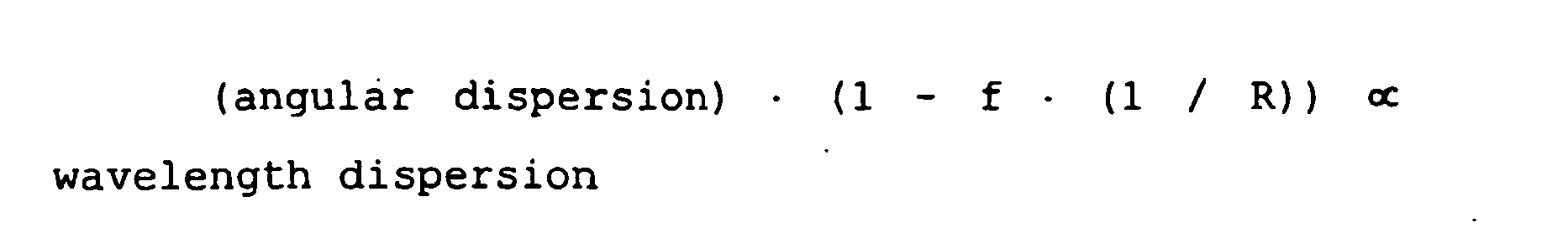
where f indicates the focal distance of thefocal lens 252, and R indicates the radius of the curvature of themirror 254. - FIG. 18 is a graph showing the angular dispersion of the
VIPA 240 for the wavelength of luminous flux. - Normally, a
curve 284 shown in FIG. 18 indicates the slope of acurve 282 shown in FIG. 17. As shown in FIG. 18, the angular dispersion is not constant. Instead, the angular dispersion changes with a wavelength. - FIG. 19 is a graph showing a part of (1 - f · (1 / R)) of the equation (3) against a wavelength.
- Further in detail, a
straight line 286 is a graph of (1 - f · (1 / R)) for the wavelength when a flat mirror is used (the radius of the curvature is ∝ (infinite)). Astraight line 288 is a graph of (1 - f · (1 / R)) for the wavelength when a concave mirror is used (the radius of the curvature is '+'). Astraight line 290 is a graph of (1 - f · (1 / R)) for the wavelength when a convex mirror is used (the radius of the curvature is '-'). As shown in FIG. 19, each mirror has a constant curvature radius. - FIG. 20 is a graph of the wavelength dispersion of the wavelength of the device as shown in FIGS. 16A and 16B.
- In these figures, the
mirror 254 is a common spherical convex mirror, a flat mirror, and a spherical concave mirror. Further in detail, acurve 292 indicates the wavelength dispersion for the wavelength when themirror 254 is a convex mirror. Acurve 294 indicates the wavelength dispersion for the wavelength when themirror 254 is a flat mirror. Acurve 296 indicates the wavelength dispersion for the wavelength when themirror 254 is a concave mirror. - Normally, as indicated by the above mentioned equation (3), the
curves curve 294 shows the product of thecurve 284 shown in FIG. 18 and thestraight line 286 shown in FIG. 19. Thecurve 296 shows the product of thecurve 284 shown in FIG. 18 and thestraight line 288 shown in FIG. 19. - As shown in FIG. 20, the wavelength dispersion is not constant although a common spherical convex mirror, flat mirror, or spherical concave mirror is used as the
mirror 256. - The above mentioned wavelength-dependency of the wavelength can be reduced or removed by chirping the curvature of the
mirror 254. - FIG. 21 is a graph of a
curve 298 of theequation 3, that is, (1 - f · (1 / R)), for the wavelength. - Normally, the
curve 298 shown in FIG. 21 is obtained by inverting thecurve 284 shown in FIG. 18. Therefore, as indicated by acurve 300 shown in FIG. 22, a mirror having the characteristics shown in FIG. 21 generates constant wavelength dispersion. - For example, FIG. 23 shows an example of the shape (section) of a dispersion mirror satisfying the
equation 3 and having a wavelength dispersion value of -2500 ps/nm. - As shown in FIG. 23, the shape of the mirror is non-spherical. The
VIPA 1 and the mirror are spatially arranged such that the angular dispersion can be parallel to the section. To set the value of the wavelength dispersion to a specific value (for example, -2500 ps/nm), the shape of the mirror can have the same shape in the direction vertical to the section (that is, a cylindrical shape). However, since rays have a focal point defined by a lens in the direction vertical to the section regardless of the wavelength, it is not necessary to set a long distance in the direction vertical to the section. - Furthermore, to obtain different levels of wavelength dispersion, the shape of the non-spherical mirror is set as a three-dimensional non-spherical mirror which gradually changes it shape in the direction vertical to the section, that is, in the direction vertical to the angular dispersion direction of the VIPA. Practically, it is the shape as shown in FIG. 24, and the section has the shape as shown in FIG. 25 in the position of the dispersion value of -500 ps/nm and +1500 ps/nm. As shown in FIG. 25, with the dispersion value changing from negative to positive, the shape changes from the non-spherical convex surface to the non-spherical concave surface. When the dispersion value is 0, the section is substantially flat. Thus, the wavelength dispersion depends on the position of the rays on the three-dimensional non-spherical mirror after the rays are output with the angular dispersion from the VIPA.
- It is not difficult to generate the above mentioned three-dimensional non-spherical mirror in the current processing technology. The process is to be performed on metal such as Al, brass, etc. with a precision three-dimensional processor having a diamond bite and a precision movable stage. Since a mirror ground by the above mentioned processor is normally expensive, it is recommended that a metal mold having an inverted shape of a necessary shape is processed, an appropriate transferring and forming process is performed on plastic, glass having a low melting point, solgel glass, etc. using the metal mold, and a mirror is finally formed by applying metal such as Au, Al, etc., or a dielectric multilayer film. In addition, such a three-dimensional shape can be obtained using ion beam etching and resists having different thicknesses.
- Furthermore, to actually vary the wavelength dispersion, it is necessary to provide a unit for moving the above mentioned three-dimensional non-spherical mirror in the direction vertical to the section, that is, in the direction vertical to the angular dispersion direction of the VIPA. That is, a unit is included for moving the above mentioned three-dimensional non-spherical mirror in the direction vertical to the angular dispersion direction of the VIPA. The moving unit can be configured mainly by, for example, a linear slider, a motor, etc. However, the components are not limited to them. That is, the linear slider can be replaced with a tremor stand, etc., and the motor can be replaced with an actuator, etc.
- According to the above mentioned arrangement, it is possible to compensate for wavelength dispersion in a practical level using a VIPA having large angular dispersion, to simultaneously compensate for dispersion at all channels of wavelength division-multiplexed rays by setting the thickness of the VIPA as the thickness of the FSR of the WDM matching, to reduce the wavelength dependency of the wavelength dispersion, that is, to have substantially constant wavelength dispersion, by having the shape of a mirror as the optimum non-spherical surface, to vary the wavelength dispersion by having the mirror as the three-dimensional non-spherical mirror and moving the three-dimensional non-spherical mirror, etc. However, a wavelength dispersion slope cannot be varied independent of the wavelength dispersion.
- In the following embodiments of the present invention, the wavelength dispersion and a wavelength dispersion slope can be varied independent of each other.
- FIG. 26 shows the configuration in which the wavelength dispersion and a wavelength dispersion slope can be varied independent of each other.
- In the principle of the present embodiment shown in FIG. 26, in addition to a VIPA, a lens, and a three-dimensional mirror, a unit for generating a parallel shift of an optical path by each wavelength, and a unit for varying the amount of the shift of the optical path are provided. According to the present principle, an optical path is shifted in parallel by a wavelength in the direction vertical to the angular dispersion direction of the VIPA, that is, in the moving direction of the mirror. Therefore, the wavelength dispersion can be varied by a wavelength, that is, a wavelength dispersion slope can be generated. Furthermore, in the above mentioned three-dimensional non-spherical mirror, a change in given wavelength dispersion is limited. Therefore, it is only necessary to invert the direction of the shift of an optical path by a wavelength to change the positive or negative state of a wavelength dispersion slope.
- Described below are some examples of a practical unit for shifting an optical path in parallel by each wavelength in the direction vertical to the angular dispersion direction of the VIPA, and a practical unit for varying the amount of the shift of the optical path.
- FIGS. 27 and 28 show the embodiments based on the above mentioned principle.
- As shown in FIG. 27A, as viewed from the side, the output rays from the
VIPA 307 are emitted in different directions depending on the wavelengths, collected on alens 308, and received by a three-dimensional mirror 309 throughparallel plates 310. Then, the rays are received on the different points of the three-dimensional mirror 309 depending on the wavelength. Therefore, different wavelength dispersion takes place depending on the wavelength, thereby performing dispersion compensation. FIG. 27B is a view from the angular dispersion direction. In this view, the rays having different wavelengths are dispersed in the direction vertical to the drawings. - According to the present embodiment, the
parallel plates 310 is inserted between thelens 308 and the three-dimensional mirror 309. The parallel plates are made of transparent materials having relatively large refractive index wavelength dispersion in an available wavelength band. Practically, it is, for example, polycrystal Si. Otherwise, it can be Ge, GaAs, etc. On both sides of the parallel plates, anti-reflection films of multilayer dielectric films are applied. - If the
parallel plates 310 are set at anangle 313 with the output ray from the pseudomiddle processing unit 8 in the direction vertical to anangular dispersion direction 312 of theVIPA 307 as shown in FIG. 28A, then the angle of the refraction of the rays depends on the refractive index of each wavelength based on the Snell's law. As a result, an optical path shift 314 is caused in parallel depending on each wavelength in the direction vertical to theangular dispersion direction 312 of theVIPA 307. With the optical path shift, the point at which a ray is received on the three-dimensional mirror 309 depending on each wavelength can be controlled independent of the angular dispersion of theVIPA 307. Therefore, the ray having each wavelength angular-dispersed by theVIPA 307 is led to the three-dimensional mirror 309, and the reflected ray is introduced to theVIPA 307 again. Accordingly, in addition to the functions of the above mentioned embodiment in which a predetermined amount of dispersion can be caused to the entire wavelength by leading a ray of each wavelength angular-dispersed by theVIPA 307 to the three-dimensional mirror 309 and inputting a reflected light to theVIPA 307 again, the amount of dispersion to each wavelength can be independently controlled by shifting the ray in the direction vertical to the angular dispersion direction of theVIPA 307, and leading the ray to the three-dimensional mirror 309. Thus, the wavelength dispersion slope can be controlled independent of the amount of wavelength dispersion.
where n1 indicates the refractive index of an input medium, θ1 indicates an incident angle, n2 indicates the refractive index of the output medium, and θ2 indicates an output angle. - Furthermore, by changing the
angle 313, the amount of the optical path shift 314 can be varied. By changing theangle 313, the amount of the optical path shift 314 is varied, and the wavelength dispersion slope can be changed. However, the optical path is simultaneously and entirely changed, and the wavelength dispersion is also changed. Therefore, it is necessary to move the three-dimensional mirror 309 such that the appropriate wavelength dispersion can take place. To obtain the appropriate wavelength dispersion and wavelength dispersion slope as described above, the angle and the position of the mirror have to be simultaneously changed. The angle can be changed by, for example, the rotation of a motor, etc. The changing method is not limited to this. - As shown in FIG. 28B, the direction of the optical path shift by a wavelength depends on whether the angle is changed in the direction A or B, thereby inverting the positive and negative state of the wavelength dispersion slope. Furthermore, the number of the parallel plates is not limited to one value. That is, there may be plural sets of parallel plates. In addition, when Si, etc. used in the present embodiment has the temperature characteristic of the refractive index of 1.5 x 10⁻⁴ (/°C), which is a large value, it may cause a change in the optical path shift depending on the temperature. However, the problem can be solved by further comprising a control device for controlling the temperature of the parallel plates. The control device for controlling the temperature comprises at least a temperature sensor such as a platinum resistance, a thermistor, etc., and a heating/cooling device such as a heater and a Peltier device, and controls the heating/cooling device such that the value of the temperature obtained from the temperature sensor can be maintained at a constant level.
- For example, when the wavelengths are 1,528 nm and 1,563 nm, the refractive indices of Si are respectively 3.47958 and 3.47666, and the difference between the refractive indices is as small as 0.003. Therefore, for example, when the thickness of an Si plate is 50 mm with an angle of 40°, the amount of the optical path shift is up to 8 µm. Therefore, although the above mentioned three-dimensional non-spherical mirror largely changes by 2,000 ps/nm per mm, only the amount of change of the wavelength dispersion up to 12 ps/nm can be made.
- Described below is another embodiment of the present invention to solve the problem with the above mentioned embodiment.
- FIG. 29 shows an embodiment of the present invention.
- According to the present embodiment, at least one
prism pair 317 configured by arranging twoprisms lens 308 and the three-dimensional mirror 309. Theprisms prisms first prism 315 is refracted by the same amount in the opposite direction by thesecond prism 316 which is arranged in parallel and in the point-symmetrical position with thefirst prism 315. As a result, the rays travel in the same direction after passing through theprism pair 317. If the rays travel in the direction vertical to the angular dispersion direction of the VIPA, the rays reflected by the three-dimensional mirror 309 are returned through the similar optical path, thereby causing no losses. - As clearly shown by the equation (4), the angle of the ray refracted by the
prisms prisms first prism 315, and the ray is refracted by the same degree in the opposite direction. As a result, an optical path shift 319 is generated in parallel by each wavelength in the direction vertical to the angular dispersion direction of the VIPA. - Furthermore, by moving one prism. 316 while maintaining the parallelism and changing the
space 318 in theprism pair 317 as shown in FIG. 30, the optical path shift 319 can be varied, and the wavelength dispersion slope can be changed. However, the optical path is simultaneously and entirely changed, and the wavelength dispersion is also changed. Therefore, it is necessary to move the three-dimensional mirror 309 such that the appropriate wavelength dispersion can take place. To obtain the appropriate wavelength dispersion and wavelength dispersion slope as described above, thespace 318 of theprism pair 317 and the position of the mirror have to be simultaneously changed. The space in theprism pair 317 can be changed by, for example, using various units as well as the above mentioned mirror moving unit, etc. The changing method is not limited to this. By rotating theprism pair 317 by 180° about the optical path as shown in FIG. 31, the direction in which an optical path shift is generated by a wavelength can be inverted to change the positive/negative state of the slope (wavelength dispersion slope) of the wavelength dispersion. The method of rotating theprism pair 317 is, but is not limited, to use, for example, a motor. In addition, when Si, etc. used in the present embodiment has the temperature characteristic of the refractive index of 1.5 x 10⁻⁴ (/°C), which is a large value, it may cause a change in the optical path shift by the change of a refractive index depending on the temperature. However, the problem can be solved by further comprising a control device for controlling the temperature of the prisms. The control device for controlling the temperature comprises at least a temperature, sensor such as a platinum resistance, a thermistor, etc., and a heating/cooling device such as a heater and a Peltier device, and controls the heating/cooling device such that the value of the temperature obtained from the temperature sensor can be maintained at a constant level. - For example, when the wavelengths are 1,528 nm and 1,563 nm, the refractive indices of Si are respectively 3.47958 and 3.47666, and the difference between the refractive indices is as small as 0.003. Therefore, for example, when the prism angle is 14° and the space in the prism pair is 50 mm, the amount of the optical path shift is up to 12 µm. Therefore, although the above mentioned three-dimensional non-spherical mirror largely changes by 2,000 ps/nm per mm, only the amount of change of the wavelength dispersion up to 25 ps/nm can be made.
- Described below is another embodiment of the present invention to solve the problem with the above mentioned embodiment.
- FIG. 32 shows an embodiment of the present invention.
- According to the present embodiment, at least one diffraction grating pair 322 configured by arranging two
diffraction gratings lens 308 and the three-dimensional mirror 309. According to the present embodiment, a transmitting blazed grating having relatively large angular dispersion in an available wavelength band and having a high primary diffraction efficiency at a predetermined angle in an available wavelength band is used as thediffraction gratings diffraction gratings - The output ray from the
lens 308 is diffracted in the direction satisfying the equation (5) by thefirst diffraction grating 320, thereby curving the optical path. At this time, the wavelength diffracting at an angle satisfying the Snell's law shown by the equation (6) has the highest diffraction efficiency, and the wavelength is referred to as a blaze wavelength. Thediffraction gratings second diffraction grating 321 arranged in the parallel and point symmetric position with thefirst diffraction grating 320. As a result, the rays travel in the same direction after passing through thediffraction grating pair 322. If the rays travel in the direction vertical to the angular dispersion direction of the VIPA, the rays reflected by the three-dimensional mirror 309 return through the similar optical path, thereby suffering no losses. - As clearly shown by the equation (5), the diffraction angle depends on the wavelength, the diffraction angle of a ray of each wavelength depends on the
first diffraction grating 320, and the ray is similarly diffracted in the opposite direction by thesecond diffraction grating 321. As a result, an optical path shift 324 is generated in parallel according to each wavelength in the direction vertical to the angular dispersion direction of the VIPA.

where β indicates a diffraction angle, N indicates the number of lines per unit length, m indicates an order, n indicates a refractive index, and θb indicates a blaze angle. - Furthermore, by moving one
diffraction grating 321 while maintaining the parallelism and changing thespace 323 in thediffraction grating pair 322 as shown in FIG. 33, the optical path shift 324 can be varied, and the wavelength dispersion slope can be changed. However, the optical path is simultaneously and entirely changed, and the wavelength dispersion is also changed. Therefore, it is necessary to move the three-dimensional mirror 309 such that the appropriate wavelength dispersion can take place. To obtain the appropriate wavelength dispersion and wavelength dispersion slope as described above, thespace 323 of thediffraction grating pair 322 and the position of the mirror have to be simultaneously changed. Thespace 323 in thediffraction grating pair 322 can be changed by, for example, using various units as well as the above mentioned mirror moving unit, etc. The changing method is not limited to this. By rotating thediffraction grating pair 322 by 180° about the optical path as shown in FIG. 34, the direction in which an optical path shift is generated by a wavelength can be inverted to change the positive/negative state of the slope (wavelength dispersion slope) of the wavelength dispersion. The method of rotating thediffraction grating pair 322 is, but is not limited, to use, for example, a motor. The number of the diffraction grating pairs 322 is not limited to one value, but there can be plural pairs. In addition, the diffraction angle of a diffraction grating is normally temperature-dependent, and it may cause a change in the optical path shift by the change of a diffraction angle depending on the temperature. However, the problem can be solved by further comprising a control device for controlling the temperature of the diffraction grating. The control device for controlling the temperature comprises at least a temperature sensor such as a platinum resistance, a thermistor, etc., and a heating/cooling device such as a heater and a Peltier device, and controls the heating/cooling device such that the value of the temperature obtained from the temperature sensor can be maintained at a constant level. - According to the present embodiment, if the number of lines is 400 per mm, the refractive index of the diffraction grating is 1.54, and the blaze angle is 39.4, then the blaze wavelength is 1,546 nm, and the diffraction angle is 38.2°. For example, if the space in the diffraction grating pair is as small as 25 mm, the amount of the optical path shift is up to 720 µm when the wavelengths are 1,528 nm and 1,563 nm. Therefore, although the above mentioned three-dimensional non-spherical mirror changes by 800 ps/nm per mm, the amount of change of the wavelength dispersion up to 25 ps/nm can be made. The amount of the compensation of the dispersion slope corresponds to 290 km with the normal SMF having the wavelength dispersion slope of 0.06 ps/nm2/km, and is a sufficient compensation amount.
- When an optical path shift is generated depending on the wavelength by the
diffraction grating pair 322, there is wavelength dispersion generated by a small optical path difference by a wavelength. However, it can be ignored because it is smaller enough than the wavelength dispersion generated by the VIPA. If it cannot be ignored, the position of the three-dimensional mirror 309 corresponding to the wavelength dispersion is adjusted to give the appropriate wavelength dispersion. - Described below is another embodiment of a method of changing the positive/negative state of the slope of wavelength dispersion (wavelength dispersion slope).
- FIG. 35 shows an embodiment of the present invention.
- According to the present embodiment, at least one of diffraction
grating pair 327 configured by twodiffraction gratings diffraction grating pair 327 as shown in FIG. 36, rays are emitted to different areas having angular dispersion in the opposite directions to generate the angular dispersion in the opposite directions and have an optical path shift 328 generated by a wavelength in the opposite direction, thereby changing the positive/negative state of the slope of wavelength dispersion (wavelength dispersion slope). The method of moving thediffraction grating pair 327 can be realized by various means as the above mentioned mirror moving unit, and is not limited to a specific method. To form different areas having angular dispersion in the opposite direction to a diffraction grating, for example, blazed gratings are formed in the opposite directions in the areas A and B. - Described below is another embodiment of a method of varying wavelength dispersion.
- FIGS. 37 and 38 show other embodiments of the present invention.
- According to the present embodiment, at least one diffraction grating pair 331 configured by two
diffraction gratings diffraction grating pair 331, rays are emitted to areas having different angular dispersion to generate different angular dispersion, vary an amount of optical path shift 332, and vary wavelength dispersion. The method of moving thediffraction grating pair 331 can be realized by various means as by the above mentioned mirror moving unit, and is not limited to a specific method. - According to some of the above mentioned embodiments, transmitting blazed grating is used as diffraction gratings, but other diffraction, gratings can be used obviously.
- For example, FIG. 39 shows another embodiment of the present invention. According to the present embodiment, a reflecting blazed grating is used as a diffraction grating. In the case of a reflecting blazed grating, an output ray from the
lens 308 is diffracted in the direction satisfying the equation (7) by thediffraction grating 333, and the optical path is curved. At this time, the wavelength diffracting at an angle satisfying the reflection law expressed by the equation (8) has the highest diffraction efficiency, and the wavelength is referred to as a blaze wavelength. Fordiffraction gratings second diffraction grating 334 arranged in the position parallel and point-symmetric with thefirst diffraction grating 333. As a result, the rays travel in the same direction after passing through adiffraction grating pair 335. If the rays travel in the direction vertical to the angular dispersion direction of the VIPA, the rays reflected by the three-dimensional mirror 309 are returned through the similar optical path, thereby causing no losses. - As clearly shown by the equation (7), the diffraction angle depends on a wavelength, a ray having each wavelength has a different diffraction angle depending on the
first diffraction grating 333, and the diffraction takes place again in the opposite direction by thesecond diffraction grating 334. As a result, an optical path shift 337 takes place by each wavelength in parallel in the direction vertical to the angular dispersion direction of the VIPA.

where α indicates an incident angle, β indicates a diffraction angle, N indicates the number of lines per unit length, m indicates an order, and θb indicates a blaze angle.' - Furthermore, the optical path shift 337 can be varied by changing a
space 336 of thediffraction grating pair 335 by moving onediffraction grating 334 while keeping the parallelism although a reflecting diffraction grating is used. - In addition, a rectangular diffraction grating, a cos curve diffraction grating, an echelon grating, etc. can be used. That is, the type of diffraction grating is not limited to a specific type.
- According to the present embodiment, an output ray for which the wavelength dispersion and a wavelength dispersion slope are compensated can be retrieved by inserting the circulator as shown in FIG. 1 into the tip of the fiber shown in FIG. 4.
- FIG. 40 shows the configuration of solving the problem of the polarized-wave-dependent losses according to the above mentioned embodiment.
- A polarized-wave-dependent loss occurs on the ray output from the
lens 8 to agrating pair 342 shown in FIG. 40 after the ray passes through blazedgratings polarization rotation element 350 is provided. The polarization of a ray reflected by the three-dimensional mirror 309 and returned is orthogonalized by 90° by thepolarization rotation element 350 in the returning path. Thepolarization rotation element 350 having the polarization rotating function can be, for example, a λ/4 wavelength plate, a Faraday rotator, etc. - Thus, if a polarized wave is rotated by 90° between going and returning paths, and the polarized-wave-dependent losses are different between the going and returning paths, then different polarized-wave-dependent losses between different polarized waves can be leveled by providing all rays in the going and returning paths with both losses, thereby leveling the difference in loss by difference in polarized wave, that is, the reduced amount of the intensity of obtained rays.
- FIG. 41 shows the configuration of continuously changing until inverting the amount of wavelength dispersion compensation provided for a ray according to an embodiment of the present invention.
- By arranging two pairs of grating
pairs 362 as shown in FIGS. 41A and 41B, and adding an offset to the variable range of a wavelength dispersion slope of thegrating pair 342 by thegrating pair 362, the function of continuously varying from the negative wavelength dispersion slope to the positive wavelength dispersion slope can be realized. That is, after thegrating pair 362 provides an offset for the optical paths of rays having different wavelengths, thespace 343 in thegrating pair 342 is appropriately adjusted, thereby outputting and crossing optical paths of rays having different wavelengths to be received by the three-dimensional mirror 309. When thespace 343 is set to another value, the optical paths of the rays having different wavelengths do not cross each other when they are received by the three-dimensional mirror 309. Thus, by adjusting thespace 343, the optical path shift of the rays having different wavelengths can be adjusted, and the points on the three-dimensional mirror 309 at which the rays are received can be exchanged. As a result, the amount of wavelength dispersion provided for each wavelength can be varied, and the amount of wavelength dispersion can be exchanged. thus, to control the value of the amount of wavelength dispersion for each wavelength is to change a wavelength dispersion slope. - FIG. 42 shows an example of a variation of the embodiment shown in FIG. 41.
- Using a grating 370, shown in FIGS. 42A and 42B, having the functions of
gratings gratings space 343 in thegratings point 344 on the three-dimensional mirror 309 on which a ray having each wavelength can be varied, and the amount of wavelength dispersion of each wavelength is varied, thereby varying a wavelength dispersion slope. - FIG. 43 shows another embodiment of the present invention.
- According to the present embodiment, a transmitting echelon grating (or referred to as a grism) is used as a diffraction grating. The transmitting echelon grating is a step type diffraction grating, and generates a phase difference by a difference in steps in forward transmission rays. Therefore, forward rays can have the highest diffraction efficiency by setting the condition such that rays having predetermined wavelengths can mutually have the phase difference as expressed by the equation (9).
- When the echelon grating is used, the output ray from the
lens 308 is diffracted by thefirst diffraction grating 438 in the direction satisfying the equation (9), and the optical path is curved. At this time, in thediffraction gratings second diffraction grating 439 arranged in the position parallel and point-symmetric with thefirst diffraction grating 438 basically as in the case of the blazed grating. Therefore, the rays travel in the same direction after passing through adiffraction grating pair 440. If the rays travel in the direction vertical to the angular dispersion direction of the VIPA, the rays reflected by the three-dimensional mirror 309 returns through the similar optical path, thereby causing no losses. - As is clearly expressed by the equation (9), the diffraction angle depends on a wavelength, a ray having each wavelength has a different diffraction angle depending on the
first diffraction grating 438, and the diffraction takes place again in the opposite direction by thesecond diffraction grating 439. As a result, an optical path shift 442 takes place by each wavelength in parallel in the direction vertical to the angular dispersion direction of the VIPA.
where n indicates a refractive index, t indicates a step difference, θ indicates a rotation angle, d indicates the space in a diffraction grating, m indicates an order, and λ indicates a wavelength. - Furthermore, an amount of optical path shift 442 can be varied by changing the
space 441 in thediffraction grating pair 440 by moving onediffraction grating 439 while maintaining the parallelism. - In the case of the echelon grating, the diffraction direction is substantially forward. Therefore, the amount of optical path shift 442 changes by changing the
space 441 in thediffraction grating pair 440. As a result, although a wavelength dispersion slope is changed, no shift is made in the optical path and no change is made in the wavelength dispersion. Therefore, it is not necessary to move the three-dimensional mirror 309 such that the appropriate wavelength dispersion can take place as in the case of the blazed grating. In addition, in the case of the blazed grating, such a large diffraction angle may cause the problem that the focal position of the rays on the three-dimensional mirror 309 is shifted in the optical path direction. However, since the diffraction direction is substantially forward in the case of the echelon grating, There occurs no problems of a shift of the focal position. - According to the present embodiment, for example, when the space in the diffraction grating is 1 µm, the step difference of the diffraction grating is 3.44 µm, and the refractive index of the diffraction grating is 1.45, the wavelengths of intensifying forward rays are 1,546 nm. For example, although the space in the diffraction grating pair is as small as 25 mm, the amount of the optical path shift is up to 940 µm for the wavelengths 1,528 nm and 1,563 nm, and the amount of the change in the wavelength dispersion up to 750 ps/nm can be assigned although the above mentioned three-dimensional non-spherical mirror shows a change of 800 ps/nm per mm. This amount of compensation of a dispersion slope corresponds to 360 km for the common SMF having the wavelength dispersion slope of 0.06 ps/nm2/km, which is a sufficient amount of compensation.
- In the embodiment shown in FIG. 43, the blazed grating shown in FIGS. 41 and 42 can be replaced with the echelon grating.
- In some of the above mentioned embodiments of the present invention, a transmitting blazed grating is used as a diffraction grating. However, other diffraction gratings can also be used.
- In the above mentioned embodiment of the present invention, the VIPA has a reflecting film for reflecting rays. For example, FIG. 7 shows the
VIPA 76 having the reflectingsurfaces - Furthermore, according to the above mentioned embodiment of the present invention, the VIPA includes a transparent glass plate generating multiple reflection. For example, FIG. 7 shows the
VIPA 76 provided with theplate 120 having a reflecting surface. However, to isolate the reflecting surface, the VIPA is not limited to a glass material or any type of plate. Instead, the reflecting surfaces have to be isolated from each other by a spacer. For example, the reflecting surface of the VIPA can be isolated by air without a glass plate. Therefore, for example, the reflecting surface can be described as being isolated by a transparent material such as an optical glass, air, etc. - The operation of the VIPA depends on the thickness and the refractive index of the material between the reflecting surfaces of the VIPA. Furthermore, the operation and the wavelength of the VIPA can be correctly adjusted by controlling the temperature of the VIPA.
- As described above, the above mentioned embodiment of the present invention can provide an apparatus for generating an arbitrary wavelength dispersion and a wavelength dispersion slope, and simultaneously dispersion-compensating the wavelength dispersion and wavelength dispersion slope actually accumulated in an optical fiber in a multichannel multiwavelength regime. Therefore, according to the embodiments of the present invention, the VIPA is not limited to a specific configuration. For example, the VIPA can have a radiation window, and the reflection on each surface of the VIPA is not limited to a specific example.
- An embodiment provides an apparatus for individually controlling the wavelength dispersion and the wavelength dispersion slope, which has not been realized by the conventional technology.
Claims (18)
- An apparatus for providing wavelength dispersion to different wavelengths of light in a ray comprising multiple wavelengths, the apparatus comprising:an optical device (76, 307) for receiving a converged light ray (77) having multiple wavelengths along an optical axis, the optical device comprising a body which is optically transparent and has two reflective surfaces (122, 124) parallel to each other and tilted at an angle (θ) relative to the optical axis, wherein at least one of the surfaces is only partially reflective, and wherein a transmission window (126) is provided which allows the converged light ray therethrough into the body so that received converged light diverges from a focal line (78) and is reflected between the reflective surfaces (122, 124) a plurality of times with the light being partially transmitted through the at least one partially reflective surface (122, 124), thereby generating angularly-dispersed output light (82) constructed through interference of the transmitted light in which different wavelengths travel in different angular directions (82a, 82b);a lens (308) for converging the output light (82) formed by the optical device; andreflecting means (309) having a surface arranged to reflect the light output from the optical device such that the light is transmitted back through the optical device (76, 307) with an optical path dependent on a position where the light is reflected off the reflecting means (309), the apparatus being characterised in that it comprises optical path shift generating means (310,317,322, 327,331,335,342,362,370,372,440) arranged to shift an optical path for each wavelength in the light converged and output from the lens (308) in a direction substantially perpendicular to the direction of angular dispersion of the optical device such that a different optical path for each wavelength of light converged and output from the lens is generated, and varying means for varying the amount of the optical path shift provided by the optical path shift generating means, the optical path shift generating means being arranged such that the light reflected by the reflecting means is transmitted back through the optical path shift generating means and the optical device with an optical path dependent on a position where the light is reflected off the reflecting means.
- The apparatus according to Claim 1, further comprising:moving means arranged to move said reflecting means (309) in a direction substantially perpendicular to the angular dispersion direction of the optical device (76, 307) .
- The apparatus according to claim 1, wherein:said optical path shift generating means comprises at least one diffraction grating pair (322, 327, 331, 335, 342, 362) comprising parallel and point-symmetric diffraction gratings arranged to provide angular dispersion in a direction substantially perpendicular to the angular dispersion direction of the optical device (76, 307); andsaid varying means comprises means for varying the space between the parallel diffraction gratings to vary the amount of the optical path shift.
- The apparatus according to Claim 1, wherein said optical path shift generating means comprises at least one diffraction grating pair (322,327, 331,335,342,362) comprising parallel and point-symmetric diffraction gratings arranged to provide angular dispersion in a direction substantially perpendicular to the angular dispersion direction of the optical device and wherein said varying means comprisesmeans for rotating the diffraction grating pair (320, 321) about the optical path thereof by 180° to invert the direction in which the optical path shift is generated and change the positive/negative state of the slope of wavelength dispersion.
- The apparatus according to Claim 1, wherein: said optical path shift generating means comprises at least one diffraction grating pair (322, 327, 331, 342, 362) comprising parallel out point-symmetric diffraction gratings arranged to provide angular dispersion in a direction substantially perpendicular to the angular dispersion direction of the optical device, and whereineach diffraction grating (325, 326) of the diffraction grating pair (327) has at least two areas (A, B) providing angular dispersion in opposite directions; andthe apparatus further comprises means for moving the diffraction gratings (325, 326) to receive the output light from the lens (308) on a different one of the areas (A, B) to invert the direction in which the optical path shift is generated and thereby change the positive/negative state of the wavelength dispersion slope.
- The apparatus according to any of Claims 3 through 5, further comprising:a control device for controlling a temperature of the diffraction grating pair to stabilize the angular dispersion.
- The apparatus according to any of Claims 3 through 5, wherein:each diffraction grating is a high diffraction efficiency blazed grating with a specific degree and wavelength.
- The apparatus according to Claim 7, wherein:each diffraction grating is a transmitting blazed grating.
- The apparatus according to Claim 7, wherein:each diffraction grating is a reflecting blazed grating.
- The apparatus according to any of Claims 3 through 5, wherein:each diffraction grating is a transmitting echelon grating.
- The apparatus according to Claim 1, wherein:said optical path shift generating means comprises at least one set of parallel plates (310) of a transparent material having refractive index wavelength dispersion; andsaid varying means comprises means for changing the angle (313) of the parallel plates relative to the output light from the lens (308) in a plane perpendicular to the direction of angular dispersion of the optical device to vary the amount of the optical path shift and the direction of the optical path shift.
- The apparatus according to Claim 11, further comprising:a control device for controlling a temperature of the parallel plates to stabilize the amount of the optical path shift.
- The apparatus according to Claim 1, wherein:said optical path shift generating means comprises at least one prism pair (317) comprising two prisms (315, 316) of transparent material having refractive index wavelength dispersion, and arranged parallel and point-symmetric with each other; andsaid varying means comprises means for varying the space between the prisms to vary the amount of the optical path shift.
- The apparatus according to Claim 1, wherein said optical phase shift generating means comprises at least one prism pair (317) comprising two prisms (315,316) of transparent material having refractive index wavelength dispersion, and arranged parallel and point-symmetric with each other, and wherein said varying means comprisesmeans for rotating the prism pair (317) by 180° about the optical path thereof to invert the direction in which the optical path shift takes place and to change the positive/negative state of the wavelength dispersion slope.
- The apparatus according to Claim 13 or 14, further comprising:a control device for controlling the temperature of the prism pair to stabilize the amount of the optical path shift.
- The apparatus according to any of Claims 11 to 15, wherein:the transparent material of said parallel plates or prisms is Si, Ge, or GaAs.
- The apparatus according to Claim 1, further comprising:a polarization rotation element (350) to compensate for a polarized-wave-dependent loss generated by said optical path shift generating means.
- The apparatus according to Claim 1, wherein:the optical path shift generating means comprises three or more parallel diffraction gratings (340, 341, 360, 361; 370, 371, 372); andthe apparatus further comprises means for varying the space (343) between a pair of the parallel diffraction gratings (340, 341; 370, 371) to vary a negative wavelength dispersion slope into a positive wavelength dispersion slope or vice versa.
Applications Claiming Priority (2)
| Application Number | Priority Date | Filing Date | Title |
|---|---|---|---|
| JP2001058947A JP3883816B2 (en) | 2001-03-02 | 2001-03-02 | Device that can vary chromatic dispersion and chromatic dispersion slope |
| JP2001058947 | 2001-03-02 |
Publications (3)
| Publication Number | Publication Date |
|---|---|
| EP1237308A2 EP1237308A2 (en) | 2002-09-04 |
| EP1237308A3 EP1237308A3 (en) | 2004-09-08 |
| EP1237308B1 true EP1237308B1 (en) | 2007-08-01 |
Family
ID=18918591
Family Applications (1)
| Application Number | Title | Priority Date | Filing Date |
|---|---|---|---|
| EP01120725A Expired - Lifetime EP1237308B1 (en) | 2001-03-02 | 2001-09-05 | Apparatus for variable wavelength dispersion and wavelength dispersion slope |
Country Status (4)
| Country | Link |
|---|---|
| US (1) | US6646805B2 (en) |
| EP (1) | EP1237308B1 (en) |
| JP (1) | JP3883816B2 (en) |
| DE (1) | DE60129665T2 (en) |
Families Citing this family (54)
| Publication number | Priority date | Publication date | Assignee | Title |
|---|---|---|---|---|
| US7053865B2 (en) * | 2001-05-31 | 2006-05-30 | Olympus Corporation | 3-D display device |
| JP2004037840A (en) | 2002-07-03 | 2004-02-05 | Olympus Corp | Dispersion compensator and dispersion compensation system |
| JP4060155B2 (en) * | 2002-09-25 | 2008-03-12 | 富士通株式会社 | Optical device |
| US20040136071A1 (en) * | 2002-10-23 | 2004-07-15 | Morey William W. | Diffractive optics assembly in an optical signal multiplexer/demultiplexer |
| US8792531B2 (en) * | 2003-02-25 | 2014-07-29 | Finisar Corporation | Optical beam steering for tunable laser applications |
| JP2004272116A (en) * | 2003-03-11 | 2004-09-30 | Fujitsu Ltd | Wavelength dispersion compensation device and optical transmission apparatus |
| JP2006086955A (en) | 2004-09-17 | 2006-03-30 | Fujitsu Ltd | Transmission characteristic evaluation system and pseudo transmission path apparatus thereof |
| JP3996927B2 (en) * | 2003-03-18 | 2007-10-24 | 富士通株式会社 | Transmission characteristic evaluation system |
| JP4021443B2 (en) * | 2003-05-12 | 2007-12-12 | 富士通株式会社 | Optical device with demultiplexing function |
| JP2005077964A (en) * | 2003-09-03 | 2005-03-24 | Fujitsu Ltd | Spectroscope apparatus |
| JP4137746B2 (en) | 2003-09-03 | 2008-08-20 | 富士通株式会社 | Method for controlling chromatic dispersion compensator and chromatic dispersion compensator |
| JP4137829B2 (en) | 2004-03-25 | 2008-08-20 | 富士通株式会社 | Chromatic dispersion compensator |
| JP4642458B2 (en) * | 2004-12-28 | 2011-03-02 | 富士通株式会社 | Wavelength dispersion generator |
| BRPI0519985B1 (en) | 2005-02-23 | 2018-01-30 | University Of Kentucky Research Foundation | METHOD FOR REDUCING THE LEVEL OF NORNICOTIN OR N'-NITROSONORNICOTIN IN A NICOTIAN GENDER PLANT OR PART OF THIS OR IN A TOBACCO PRODUCT, EXPRESSION CASSETTE AND METHOD FOR THE PRODUCTION OF A NICOTIAN GENDER PLANT |
| JP2006243500A (en) * | 2005-03-04 | 2006-09-14 | Fujitsu Ltd | Wavelength dispersion compensator |
| JP4545023B2 (en) | 2005-03-14 | 2010-09-15 | 富士通株式会社 | Chromatic dispersion and dispersion slope compensator |
| JP4540520B2 (en) | 2005-03-28 | 2010-09-08 | 富士通株式会社 | Dispersion slope compensator |
| JP4038216B2 (en) | 2005-05-10 | 2008-01-23 | ファナック株式会社 | Sequence program editing device |
| US20060272057A1 (en) | 2005-05-25 | 2006-11-30 | Pioneer Hi-Bred International, Inc. | Methods for improving crop plant architecture and yield |
| AU2007212168A1 (en) | 2006-02-09 | 2007-08-16 | Pioneer Hi-Bred International, Inc. | Genes for enhancing nitrogen utilization efficiency in crop plants |
| US20100284076A1 (en) * | 2006-04-07 | 2010-11-11 | Fujitsu Limited | Wavelength dispersion compensation device |
| JP2007298968A (en) * | 2006-04-07 | 2007-11-15 | Fujitsu Ltd | Wavelength dispersion compensation device |
| EP2251349A1 (en) | 2006-04-19 | 2010-11-17 | Pioneer Hi-Bred International, Inc. | Isolated polynucleotide molecules corresponding to mutant and wild-type alleles of the maize D9 gene and methods of use |
| BRPI0820042B1 (en) | 2007-11-12 | 2020-05-19 | North Carolina State University | method of obtaining a tobacco plant, or cell or part thereof, having reduced levels of nornicotine, tobacco product, method of making a tobacco product, isolated polynucleotide, expression cassette, isolated polypeptide and method of obtaining a plant, or part of this plant, of the genus nicotiana |
| WO2009067580A2 (en) | 2007-11-20 | 2009-05-28 | Pioneer Hi-Bred International, Inc. | Maize ethylene signaling genes and modulation of same for improved stress tolerance in plants |
| JP2009152857A (en) | 2007-12-20 | 2009-07-09 | Fujitsu Ltd | Variable dispersion compensation control method and variable dispersion compensation control device |
| DE102008022724B4 (en) | 2008-05-06 | 2010-02-11 | Freie Universität Berlin | Pulse shaper and infrared laser with pulse shaper |
| EP2821490A3 (en) | 2008-10-30 | 2015-04-22 | Pioneer Hi-Bred International Inc. | Manipulation of glutamine synthetases (GS) to improve nitrogen use efficiency and grain yield in higher plants |
| WO2010065867A1 (en) | 2008-12-04 | 2010-06-10 | Pioneer Hi-Bred International, Inc. | Methods and compositions for enhanced yield by targeted expression of knotted1 |
| WO2010101818A1 (en) | 2009-03-02 | 2010-09-10 | Pioneer Hi-Bred International, Inc. | Nac transcriptional activators involved in abiotic stress tolerance |
| AU2010274146A1 (en) | 2009-07-24 | 2012-02-02 | Pioneer Hi-Bred International, Inc. | The use of dimerization domain component stacks to modulate plant architecture |
| EP2521788A1 (en) | 2010-01-06 | 2012-11-14 | Pioneer Hi-Bred International Inc. | Identification of diurnal rhythms in photosynthetic and non-photosynthetic tissues from zea mays and use in improving crop plants |
| US9512188B2 (en) | 2010-07-12 | 2016-12-06 | The State Of Israel, Ministry Of Agriculture & Rural Development, Agricultural Research Organization (Aro) (Volcani Center) | Isolated polynucleotides and methods and plants using same for regulating plant acidity |
| WO2012115077A1 (en) * | 2011-02-24 | 2012-08-30 | オリンパス株式会社 | Wavelength selection switch |
| US20140216118A1 (en) | 2011-06-14 | 2014-08-07 | Synthon Biopharmaceuticals B.V. | Compositions and Methods for Making and Biocontaining Auxotrophic Transgenic Plants |
| US20150159166A1 (en) | 2011-10-31 | 2015-06-11 | Pioneer Hi Bred International Inc | Plant drought tolerance and nitrogen use efficiency by reducing plant sensitivity to ethylene |
| UA116097C2 (en) | 2011-12-11 | 2018-02-12 | Зе Стейт Оф Ізраел, Міністрі Оф Агрікалче Енд Руерал Девелопмент, Агрікалчерал Рісьоч Організейшн, (А.Р.О.), Волкані Сентре | Methods of modulating stomata conductance and plant expression constructs for executing same |
| CN104703998B (en) | 2012-03-13 | 2020-08-21 | 先锋国际良种公司 | Genetic reduction of male fertility in plants |
| WO2013138309A1 (en) | 2012-03-13 | 2013-09-19 | Pioneer Hi-Bred International, Inc. | Genetic reduction of male fertility in plants |
| US20160002648A1 (en) | 2013-03-11 | 2016-01-07 | Mei Guo | Genes for improving nutrient uptake and abiotic stress tolerance in plants |
| US20160010101A1 (en) | 2013-03-13 | 2016-01-14 | Pioneer Hi-Bred International, Inc. | Enhanced nitrate uptake and nitrate translocation by over- expressing maize functional low-affinity nitrate transporters in transgenic maize |
| WO2014164116A1 (en) | 2013-03-13 | 2014-10-09 | Pioneer Hi-Bred International, Inc. | Functional expression of bacterial major facilitator superfamily (sfm) gene in maize to improve agronomic traits and grain yield |
| CA2903693A1 (en) | 2013-03-14 | 2014-10-02 | Pioneer Hi-Bred International, Inc. | Maize stress related transcription factor 18 and uses thereof |
| WO2014172035A1 (en) * | 2013-03-15 | 2014-10-23 | University Of Utah Research Foundation | Coherent fluorescence super-resolution microscopy |
| US20140283216A1 (en) | 2013-03-15 | 2014-09-18 | Pioneer Hi Bred International Inc | Compositions and methods of use of acc oxidase polynucleotides and polypeptides |
| US20170166920A1 (en) | 2014-01-30 | 2017-06-15 | Two Blades Foundation | Plants with enhanced resistance to phytophthora |
| WO2015171603A1 (en) | 2014-05-06 | 2015-11-12 | Two Blades Foundation | Methods for producing plants with enhanced resistance to oomycete pathogens |
| JP2017049555A (en) * | 2015-09-04 | 2017-03-09 | シャープ株式会社 | Optical device and projection device comprising the same |
| WO2017062790A1 (en) | 2015-10-09 | 2017-04-13 | Two Blades Foundation | Cold shock protein receptors and methods of use |
| MX2018011298A (en) | 2016-03-18 | 2019-03-07 | Pioneer Hi Bred Int | Methods and compositions for producing clonal, non-reduced, non-recombined gametes. |
| US9720250B1 (en) * | 2016-04-05 | 2017-08-01 | Dicon Fiberobtics, Inc. | Tunable optical filter with adjustable bandwidth |
| US10955668B2 (en) * | 2017-02-14 | 2021-03-23 | Optecks, Llc | Optical display system for augmented reality and virtual reality |
| WO2021019536A1 (en) | 2019-07-30 | 2021-02-04 | The State Of Israel, Ministry Of Agriculture & Rural Development, Agricultural Research Organization (Aro) (Volcani Center) | Methods of controlling cannabinoid synthesis in plants or cells and plants and cells produced thereby |
| CN114488408A (en) * | 2022-01-20 | 2022-05-13 | 昂纳信息技术(深圳)有限公司 | Tunable optical filter and optical channel monitoring module |
Citations (2)
| Publication number | Priority date | Publication date | Assignee | Title |
|---|---|---|---|---|
| US3675154A (en) * | 1970-10-01 | 1972-07-04 | Bell Telephone Labor Inc | Dispersion compensation in lasers |
| US3943457A (en) * | 1974-10-16 | 1976-03-09 | The United States Of America As Represented By The Secretary Of The Navy | Optical pulse compression and shaping system |
Family Cites Families (20)
| Publication number | Priority date | Publication date | Assignee | Title |
|---|---|---|---|---|
| JPS58121694A (en) * | 1982-01-13 | 1983-07-20 | Nec Corp | Fiber raman laser |
| ATE126883T1 (en) * | 1989-06-16 | 1995-09-15 | Fisons Plc | OPTICAL SYSTEM FOR SPECTRA ANALYSIS. |
| JPH03294815A (en) * | 1990-04-13 | 1991-12-26 | Nippon Telegr & Teleph Corp <Ntt> | Ultrashort light pulse supply device |
| JPH05102587A (en) * | 1991-10-07 | 1993-04-23 | Nec Corp | Narrow-band excimer laser |
| JPH06331850A (en) * | 1993-05-25 | 1994-12-02 | Matsushita Electric Ind Co Ltd | Optical filter and diffraction element used therefor |
| US5969865A (en) * | 1995-07-26 | 1999-10-19 | Fujitsu Limited | Optical apparatus which uses a virtually imaged phased array to produce chromatic dispersion |
| US5930045A (en) | 1995-07-26 | 1999-07-27 | Fujitsu, Ltd. | Optical apparatus which uses a virtually imaged phased array to produce chromatic dispersion |
| US5973838A (en) | 1995-07-26 | 1999-10-26 | Fujitsu Limited | Apparatus which includes a virtually imaged phased array (VIPA) in combination with a wavelength splitter to demultiplex wavelength division multiplexed (WDM) light |
| JP3464081B2 (en) | 1995-07-26 | 2003-11-05 | 富士通株式会社 | Wavelength splitter |
| JP3294986B2 (en) | 1996-03-22 | 2002-06-24 | 富士通株式会社 | Optical element without temperature dependence |
| JP3274058B2 (en) | 1996-03-22 | 2002-04-15 | 富士通株式会社 | Optical device |
| US5796479A (en) * | 1997-03-27 | 1998-08-18 | Hewlett-Packard Company | Signal monitoring apparatus for wavelength division multiplexed optical telecommunication networks |
| US6343866B1 (en) * | 2000-05-23 | 2002-02-05 | Fujitsu Limited | Optical apparatus which uses a virtually imaged phased array to produce chromatic dispersion |
| US6332689B1 (en) * | 1999-12-14 | 2001-12-25 | Fujitsu Limited | Optical apparatus which uses a virtually imaged phased array to produce chromatic dispersion |
| CN100514118C (en) * | 1999-12-14 | 2009-07-15 | 富士通株式会社 | optical apparatus which uses virtually imaged phased array to produce chromatic dispersion |
| US6296361B1 (en) * | 1999-12-14 | 2001-10-02 | Fujitsu Limited | Optical apparatus which uses a virtually imaged phased array to produced chromatic dispersion |
| US7075963B2 (en) * | 2000-01-27 | 2006-07-11 | Lambda Physik Ag | Tunable laser with stabilized grating |
| US6441959B1 (en) * | 2000-05-19 | 2002-08-27 | Avanex Corporation | Method and system for testing a tunable chromatic dispersion, dispersion slope, and polarization mode dispersion compensator utilizing a virtually imaged phased array |
| US6301048B1 (en) * | 2000-05-19 | 2001-10-09 | Avanex Corporation | Tunable chromatic dispersion and dispersion slope compensator utilizing a virtually imaged phased array |
| US6392807B1 (en) * | 2000-12-22 | 2002-05-21 | Avanex Corporation | Tunable chromatic dispersion compensator utilizing a virtually imaged phased array and folded light paths |
-
2001
- 2001-03-02 JP JP2001058947A patent/JP3883816B2/en not_active Expired - Fee Related
- 2001-08-28 US US09/939,566 patent/US6646805B2/en not_active Expired - Fee Related
- 2001-09-05 DE DE60129665T patent/DE60129665T2/en not_active Expired - Lifetime
- 2001-09-05 EP EP01120725A patent/EP1237308B1/en not_active Expired - Lifetime
Patent Citations (2)
| Publication number | Priority date | Publication date | Assignee | Title |
|---|---|---|---|---|
| US3675154A (en) * | 1970-10-01 | 1972-07-04 | Bell Telephone Labor Inc | Dispersion compensation in lasers |
| US3943457A (en) * | 1974-10-16 | 1976-03-09 | The United States Of America As Represented By The Secretary Of The Navy | Optical pulse compression and shaping system |
Non-Patent Citations (1)
| Title |
|---|
| BRADFORD C.: "Managing chromatic dispersion increases bandwidth", LASER FOCUS WORLD, FEBRUAR 2001, 1 February 2001 (2001-02-01), pages 71 - 75, XP001246602 * |
Also Published As
| Publication number | Publication date |
|---|---|
| JP3883816B2 (en) | 2007-02-21 |
| US20020122256A1 (en) | 2002-09-05 |
| EP1237308A3 (en) | 2004-09-08 |
| JP2002258207A (en) | 2002-09-11 |
| US6646805B2 (en) | 2003-11-11 |
| DE60129665D1 (en) | 2007-09-13 |
| DE60129665T2 (en) | 2008-04-17 |
| EP1237308A2 (en) | 2002-09-04 |
Similar Documents
| Publication | Publication Date | Title |
|---|---|---|
| EP1237308B1 (en) | Apparatus for variable wavelength dispersion and wavelength dispersion slope | |
| US5969865A (en) | Optical apparatus which uses a virtually imaged phased array to produce chromatic dispersion | |
| US5930045A (en) | Optical apparatus which uses a virtually imaged phased array to produce chromatic dispersion | |
| US6296361B1 (en) | Optical apparatus which uses a virtually imaged phased array to produced chromatic dispersion | |
| US6343866B1 (en) | Optical apparatus which uses a virtually imaged phased array to produce chromatic dispersion | |
| US20050174653A1 (en) | Optical apparatus which uses a virtually imaged phased array to produce chromatic dispersion | |
| US6714705B1 (en) | Tunable chromatic dispersion and dispersion slope compensator utilizing a virtually imaged phased array and a rotating grating | |
| US7200297B2 (en) | Device using a virtually-imaged phased array (VIPA) with an improved transmission wave characteristic of output light | |
| US6836580B2 (en) | Wavelength dispersion compensation system for compensating even for higher-order dispersion |
Legal Events
| Date | Code | Title | Description |
|---|---|---|---|
| PUAI | Public reference made under article 153(3) epc to a published international application that has entered the european phase |
Free format text: ORIGINAL CODE: 0009012 |
|
| AK | Designated contracting states |
Kind code of ref document: A2 Designated state(s): AT BE CH CY DE DK ES FI FR GB GR IE IT LI LU MC NL PT SE TR |
|
| AX | Request for extension of the european patent |
Free format text: AL;LT;LV;MK;RO;SI |
|
| PUAL | Search report despatched |
Free format text: ORIGINAL CODE: 0009013 |
|
| AK | Designated contracting states |
Kind code of ref document: A3 Designated state(s): AT BE CH CY DE DK ES FI FR GB GR IE IT LI LU MC NL PT SE TR |
|
| AX | Request for extension of the european patent |
Extension state: AL LT LV MK RO SI |
|
| 17P | Request for examination filed |
Effective date: 20040923 |
|
| 17Q | First examination report despatched |
Effective date: 20041015 |
|
| AKX | Designation fees paid |
Designated state(s): DE FR GB |
|
| GRAP | Despatch of communication of intention to grant a patent |
Free format text: ORIGINAL CODE: EPIDOSNIGR1 |
|
| GRAS | Grant fee paid |
Free format text: ORIGINAL CODE: EPIDOSNIGR3 |
|
| GRAA | (expected) grant |
Free format text: ORIGINAL CODE: 0009210 |
|
| AK | Designated contracting states |
Kind code of ref document: B1 Designated state(s): DE FR GB |
|
| REG | Reference to a national code |
Ref country code: GB Ref legal event code: FG4D |
|
| REF | Corresponds to: |
Ref document number: 60129665 Country of ref document: DE Date of ref document: 20070913 Kind code of ref document: P |
|
| ET | Fr: translation filed | ||
| PLBE | No opposition filed within time limit |
Free format text: ORIGINAL CODE: 0009261 |
|
| STAA | Information on the status of an ep patent application or granted ep patent |
Free format text: STATUS: NO OPPOSITION FILED WITHIN TIME LIMIT |
|
| 26N | No opposition filed |
Effective date: 20080506 |
|
| PGFP | Annual fee paid to national office [announced via postgrant information from national office to epo] |
Ref country code: GB Payment date: 20090902 Year of fee payment: 9 |
|
| PGFP | Annual fee paid to national office [announced via postgrant information from national office to epo] |
Ref country code: DE Payment date: 20090903 Year of fee payment: 9 |
|
| PGFP | Annual fee paid to national office [announced via postgrant information from national office to epo] |
Ref country code: FR Payment date: 20091012 Year of fee payment: 9 |
|
| GBPC | Gb: european patent ceased through non-payment of renewal fee |
Effective date: 20100905 |
|
| REG | Reference to a national code |
Ref country code: FR Ref legal event code: ST Effective date: 20110531 |
|
| REG | Reference to a national code |
Ref country code: DE Ref legal event code: R119 Ref document number: 60129665 Country of ref document: DE Effective date: 20110401 |
|
| PG25 | Lapsed in a contracting state [announced via postgrant information from national office to epo] |
Ref country code: FR Free format text: LAPSE BECAUSE OF NON-PAYMENT OF DUE FEES Effective date: 20100930 Ref country code: DE Free format text: LAPSE BECAUSE OF NON-PAYMENT OF DUE FEES Effective date: 20110401 |
|
| PG25 | Lapsed in a contracting state [announced via postgrant information from national office to epo] |
Ref country code: GB Free format text: LAPSE BECAUSE OF NON-PAYMENT OF DUE FEES Effective date: 20100905 |