EP1237261A1 - Method for manufacturing an encapsulated rotor of a permanent magnet motor - Google Patents
Method for manufacturing an encapsulated rotor of a permanent magnet motor Download PDFInfo
- Publication number
- EP1237261A1 EP1237261A1 EP01104790A EP01104790A EP1237261A1 EP 1237261 A1 EP1237261 A1 EP 1237261A1 EP 01104790 A EP01104790 A EP 01104790A EP 01104790 A EP01104790 A EP 01104790A EP 1237261 A1 EP1237261 A1 EP 1237261A1
- Authority
- EP
- European Patent Office
- Prior art keywords
- sheet metal
- rotor
- preform
- metal jacket
- shaft
- Prior art date
- Legal status (The legal status is an assumption and is not a legal conclusion. Google has not performed a legal analysis and makes no representation as to the accuracy of the status listed.)
- Granted
Links
Images
Classifications
-
- H—ELECTRICITY
- H02—GENERATION; CONVERSION OR DISTRIBUTION OF ELECTRIC POWER
- H02K—DYNAMO-ELECTRIC MACHINES
- H02K15/00—Methods or apparatus specially adapted for manufacturing, assembling, maintaining or repairing of dynamo-electric machines
- H02K15/02—Methods or apparatus specially adapted for manufacturing, assembling, maintaining or repairing of dynamo-electric machines of stator or rotor bodies
- H02K15/03—Methods or apparatus specially adapted for manufacturing, assembling, maintaining or repairing of dynamo-electric machines of stator or rotor bodies having permanent magnets
-
- Y—GENERAL TAGGING OF NEW TECHNOLOGICAL DEVELOPMENTS; GENERAL TAGGING OF CROSS-SECTIONAL TECHNOLOGIES SPANNING OVER SEVERAL SECTIONS OF THE IPC; TECHNICAL SUBJECTS COVERED BY FORMER USPC CROSS-REFERENCE ART COLLECTIONS [XRACs] AND DIGESTS
- Y10—TECHNICAL SUBJECTS COVERED BY FORMER USPC
- Y10T—TECHNICAL SUBJECTS COVERED BY FORMER US CLASSIFICATION
- Y10T29/00—Metal working
- Y10T29/49—Method of mechanical manufacture
- Y10T29/49002—Electrical device making
- Y10T29/49009—Dynamoelectric machine
- Y10T29/49012—Rotor
-
- Y—GENERAL TAGGING OF NEW TECHNOLOGICAL DEVELOPMENTS; GENERAL TAGGING OF CROSS-SECTIONAL TECHNOLOGIES SPANNING OVER SEVERAL SECTIONS OF THE IPC; TECHNICAL SUBJECTS COVERED BY FORMER USPC CROSS-REFERENCE ART COLLECTIONS [XRACs] AND DIGESTS
- Y10—TECHNICAL SUBJECTS COVERED BY FORMER USPC
- Y10T—TECHNICAL SUBJECTS COVERED BY FORMER US CLASSIFICATION
- Y10T29/00—Metal working
- Y10T29/49—Method of mechanical manufacture
- Y10T29/49002—Electrical device making
- Y10T29/4902—Electromagnet, transformer or inductor
- Y10T29/49075—Electromagnet, transformer or inductor including permanent magnet or core
- Y10T29/49076—From comminuted material
Definitions
- the invention relates to a method for producing an encapsulated rotor a permanent magnet motor.
- the rotors of permanent magnet motors are permanent magnets either directly on the motor shaft or on one on the rotor shaft to arrange seated rotor iron part, for example a rotor laminated core. It can be individual magnets to be distributed over the circumference or also one or more ring-shaped magnets, which are polarized accordingly. Because the pending on the motor shaft Torques on the magnetic flux between the stator and rotor and thus also generated via the permanent magnets located therein the magnets must be fastened appropriately in a stable manner.
- mechanical solutions such as those from the US patents 4855630 and 5140210 or 5627423 are known. Such mechanical Fasteners are not only complex to manufacture, but tend to be in addition to unbalance, which may need to be compensated are.
- the invention is based on the object Process for producing an encapsulated rotor of a permanent magnet motor to create with such rotors in series, in particular Large-scale production can be manufactured inexpensively, in particular while avoiding the aforementioned disadvantages.
- the method according to the invention is structured as follows:
- the dimensioning of the preform and sheet metal jacket is designed so that the jacket is on the press during the pressing process Press tool can expand radially. After this forming process the metal jacket is closed on both ends by a cover. The lids are sealed on the inside with the shaft or with the Rotor iron part and tightly connected on the outside to the sheet metal jacket. The magnetization and hardening of the molding takes place after the Pressing process.
- each is the understood magnetic flux conducting component between shaft and magnet.
- a component can typically be provided by a rotor laminated core or a ferritic sintered body can also be formed.
- the method according to the invention not only creates an intimate, non-positive Bond between the molding or the magnet, the Sheet metal jacket and the rotor iron part or the shaft, but ensures about it Practical in one step, even for a high radial Dimensional accuracy of the rotor.
- Another significant advantage of the invention The method consists in particular in that with a Rotor plate package, the rotor is equipped with the rotor plate package on the outer circumference does not have to be processed separately since the preform is through the pressing process flush to the outside of the rotor core invests.
- Another significant advantage of the method according to the invention is that no adhesive is used for magnetic attachment must be, in particular at high operating temperatures in its Strength properties deteriorates.
- the preform can consist of several parts, for example in the form of ring segments or axially adjacent rings or ring segments his.
- the preform preferably consists of two axially to one another adjacent rings, preferably from both axial sides at the same time or pressurized one after the other.
- the lid by sheet metal parts on the inside welded to the shaft and on the outside to the sheet metal jacket become.
- the sheet metal jacket instead of the shaft with the rotor iron part to be welded in order to achieve a tight encapsulation.
- the edge of the lid is welded to the sheet metal jacket in one area, which is so far away from the molding or the magnet that a noticeable heat effect, especially one that affects the magnet Avoidance of heat from the welding process becomes.
- the welding process can therefore also be carried out after magnetization respectively.
- the welding of the jacket and lid to be carried out from the outside of the jacket, by welding through the jacket, for example using a laser becomes.
- the pressing tool, jacket and preform are expediently so dimensioned that the jacket during the pressing process on its elasticity is plastically deformed. This deformation of the jacket the rotor can be calibrated at the same time, so that no separate operation is required.
- the magnetization and hardening of the molding can generally be increased any time after the forming process. If a hardening caused by external heat, the magnetization and subsequent hardening advantageous before connecting the sheet metal jacket with the lids, because of the heat during the hardening process any remaining moisture or gases removed become.
- hardening can occur may be dispensed with by external heat, then the hardening takes place during operation of the engine, for example during a test run specially conditioned for this or else during normal operation. If necessary, a hardening of the magnet can also be completely dispensed with, as this is mechanical firmly between sheet metal jacket and shaft or sheet metal jacket and rotor iron part is clamped and otherwise no mechanical stress subject.
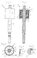
- the rotor 1 shown in detail with reference to FIGS. 1 to 5 exists from a shaft 2 on which a rotor core 3 is fastened.
- the rotor core package 3 is surrounded on the circumference by a molding 4, which is made of two rings butting against each other and aligned with each other 5 exists and which forms the magnet of the rotor.
- the rotor core package 3 is unprocessed on the circumference, the blank 4 closes over the entire surface and flush with this unprocessed outer circumference of the rotor laminated core 3 on and is non-positively connected to it.
- the molding 4 is essentially on its outer circumference surrounded cylindrical sheet metal jacket 6, over the entire outer circumference of the molded article 4 abuts against this and non-positively with this connected is.
- the area between shaft 2 and sheet metal jacket 6 is through two covers 7 completed, each in the between sheet metal jacket 6 and shaft 2 immerse the space formed and are formed by sheet metal parts.
- the Cover 7 have a protruding both outwards and inwards Edge 8 or 9 on which they overlap with the protruding from the molding 4 Part of the sheet metal jacket 6 or the shaft 2 are welded.
- the Detail IV according to Figure 4 clearly shows the outer edge 9, the inside of the sheet metal jacket 6 rests and is welded to it all around. The The sheet metal jacket 6 projects axially beyond the edge 9.
- the detail V according to FIG. 5 shows the welding of the inner edge 8 with the shaft 2, namely via a face lying on the inner edge 8 Fillet weld between shaft 2 and cover 7.
- the cover 7 points over it also eight dome-shaped impressions 10, which for stabilization and serve to avoid vibrations.
- the rotor 1 described above is with respect to the rotor core 3 and of the blank 4, which forms the magnet, through the sheet metal jacket 6 and the cover 7 and the shaft 2 hermetically sealed and ready for use determined in the canned tube of a wet-running engine.
- the shaft 2 contributes to this both sides of the rotor laminated core 3 beyond the cover 7 thrust bearing.
- the long, free shaft end carries, for example, a rotor of a circulation pump.
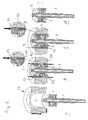
- a first step a the shaft 2 with the on it attached rotor laminated core 3, the cylindrical metal jacket 6 and a Preform 11 - (this is shown in step b) in a pressing tool 12 inserted.
- the preform 11 consists of two of the same size and aligned adjacent rings made of a pre-sintered magnetizable Neodynium-based material. The pre-sintering takes place in such a way that a firm hold of the preform 11, i.e. of the two rings and one there is sufficient dimensional stability, but further deformability is possible, i.e. curing has not yet taken place.
- the components are coordinated so that they lie in one another with play, wherein the preform 11 in its axial length to the rotor core 3 towered over on both sides.
- the space formed between the rotor laminated core 3 and the metal jacket 6 and the diameter of the sheet metal jacket 6 are chosen so that when the preform 11 becomes the molding 4 pressed in FIG. 6c has been reshaped, this not only over the entire surface and non-positively on Outer circumference of the rotor laminated core 3 and on the inner circumference of the laminated shell 6 is present, but also that the sheet metal jacket due to of the forming pressure radially plastically until it rests on the pressing tool 12 deformed and thus calibrated.
- the preform 11 formed blank 4 from two rings, whereby a more uniform material flow should be achieved during the pressing process.
- stamps 13 from above and from below are supportive for application the pressure forces provided.
- the molding or the preform can in principle also be formed in one piece or can consist of several segments.
Abstract
Description
Die Erfindung betrifft ein Verfahren zur Herstellung eines gekapselten Rotors eines Permanentmagnetmotors.The invention relates to a method for producing an encapsulated rotor a permanent magnet motor.
Bei Rotoren von Permanentmagnetmotoren sind Permanentmagnete entweder direkt auf der Motorwelle oder auf einem auf der Rotorwelle sitzenden Rotoreisenteil, beispielsweise einem Rotorblechpaket anzuordnen. Es kann sich dabei um über den Umfang zu verteilende Einzelmagnete oder auch um ein oder mehrere ringförmige Magnete handeln, die entsprechend polarisiert sind. Da die an der Motorwelle anstehenden Drehmomente über den magnetischen Fluss zwischen Stator und Rotor und somit auch über die darin befindlichen Permanentmagnete erzeugt werden, sind die Magnete entsprechend stabil zu befestigen. Hierzu gibt es mechanische Lösungen, wie sie beispielsweise aus den US-Patenten 4855630 und 5140210 oder 5627423 bekannt sind. Solche mechanischen Befestigungen sind nicht nur aufwändig in der Fertigung, sondern neigen darüber hinaus zu Unwuchten, die gegebenenfalls noch auszugleichen sind.The rotors of permanent magnet motors are permanent magnets either directly on the motor shaft or on one on the rotor shaft to arrange seated rotor iron part, for example a rotor laminated core. It can be individual magnets to be distributed over the circumference or also one or more ring-shaped magnets, which are polarized accordingly. Because the pending on the motor shaft Torques on the magnetic flux between the stator and rotor and thus also generated via the permanent magnets located therein the magnets must be fastened appropriately in a stable manner. There are there mechanical solutions, such as those from the US patents 4855630 and 5140210 or 5627423 are known. Such mechanical Fasteners are not only complex to manufacture, but tend to be in addition to unbalance, which may need to be compensated are.
Derartige mechanische Befestigungen sind darüber hinaus häufig dann nicht praktikabel, wenn der Rotor, wie bei Naßlaufmotoren üblich, vollständig gekapselt sein muss. Insbesondere bei den heutzutage verwendeten Magneten auf Neodyniumbasis muss unter allen Umständen verhindert werden, dass diese mit Wasser oder Feuchtigkeit in Verbindung kommen. Hier reichen Kunststoffummantelungen regelmäßig nicht aus, da sie in der Regel nicht diffusionsdicht sind.Such mechanical fastenings are also often then not practical if the rotor, as is usual with wet-running motors, is complete must be encapsulated. Especially those used today Neodynium based magnets must be prevented under all circumstances that they come into contact with water or moisture. Plastic sheathing is usually not sufficient here because it is in the Are usually not diffusion-tight.
Aus dem US-Patent 5,495,658 ist ein Verfahren bekannt, bei dem in dem späteren Rotormantel der Magnet eingeformt und gesintert wird, erst danach wird die Welle eingesetzt. Hierdurch soll die Maßhaltigkeit insbesondere am Rotormantel besonders gut sein. Das dort beschriebene Herstellungsverfahren ist jedoch für die Großserienfertigung gekapselter Rotoren wenig geeignet. Zum einen stellt die Befestigung der Welle ein Problem dar und zum anderen werden durch das Einpressen hohe Zugspannungen in den Magneten eingebracht, was nach dem Härten desselben vermieden werden sollte. Darüber hinaus ist dieses Herstellungsverfahren für mit einem Rotorblechpaket versehene Rotoren nicht geeignet, da die Verbindung zwischen Rotorblechpaket und Magnet nicht oder nur schwer steuerbar ist und in jedem Fall das Rotorblechpaket umfangseitig spanabhebend bearbeitet werden muss.A method is known from US Pat. No. 5,495,658 in which later rotor jacket the magnet is molded and sintered, first then the shaft is inserted. This should ensure dimensional accuracy in particular be particularly good on the rotor shell. The one described there However, manufacturing process is more encapsulated for mass production Rotors not very suitable. On the one hand, the fastening of the shaft stops Problem and on the other hand, high tensile stresses result from the pressing introduced into the magnet, which after hardening it should be avoided. In addition, this manufacturing process not suitable for rotors equipped with a rotor laminated core, because the connection between the rotor laminated core and the magnet is not or only is difficult to control and in any case the rotor core package on the circumference must be machined.
Vor diesem Hintergrund liegt der Erfindung die Aufgabe zugrunde, ein Verfahren zur Herstellung eines gekapselten Rotors eines Permanentmagnetmotors zu schaffen, mit dem solche Rotoren in der Serien-, insbesondere Großserienfertigung kostengünstig gefertigt werden können, insbesondere unter Vermeidung der vorgenannten Nachteile.Against this background, the invention is based on the object Process for producing an encapsulated rotor of a permanent magnet motor to create with such rotors in series, in particular Large-scale production can be manufactured inexpensively, in particular while avoiding the aforementioned disadvantages.
Diese Aufgabe wird gemäß der Erfindung durch das in Anspruch 1 definierte
Verfahren gelöst. Vorteilhafte Ausgestaltungen und Weiterbildungen
des Verfahrens sowie der Aufbau eines solchen Rotors sind in den
Unteransprüchen, der nachfolgenden Beschreibung und der Zeichnung
angegeben.This object is achieved according to the invention by that defined in
Das erfindungsgemäße Verfahren gliedert sich wie folgt:The method according to the invention is structured as follows:
Es wird zunächst einmal eine Welle oder gegebenenfalls eine bereits mit einem Rotoreisenteil versehene Welle mit einem gegebenenfalls mehrteiligen Vorformling, der den späteren Magneten bildet, und mit einem zylindrischen Blechabschnitt, der den späteren Blechmantel bildet, in ein Presswerkzeug eingelegt. Die Bauteile weisen dabei ausreichendes Spiel zueinander auf, so dass sie praktisch ohne Kraftaufwand ineinander gefügt werden können. In einem oder mehreren Pressvorgängen wird dann der Vorformling durch stirnseitige Druckkraftbeaufschlagung so weit verformt, dass er innen an der Welle (wenn der Magnet direkt auf der Welle sitzt) oder am Rotoreisenteil und außen am Blechmantel kraftschlüssig anliegt. First of all, there will be a wave or possibly one with a rotor iron part provided with a possibly multi-part shaft Preform that forms the later magnet, and with a cylindrical sheet metal section, which forms the later sheet metal jacket, in one Press tool inserted. The components have sufficient play to each other so that they fit into each other with practically no effort can be. In one or more pressing processes, the Preform deformed so far due to the application of pressure on the end face that it is on the inside of the shaft (if the magnet sits directly on the shaft) or is non-positively on the rotor iron part and on the outside of the sheet metal jacket.
Dabei ist die Dimensionierung von Vorformling und Blechmantel so gestaltet, dass sich der Mantel während des Pressvorgangs bis zur Anlage am Presswerkzeug radial aufweiten kann. Nach diesem Umformvorgang wird der Blechmantel an beiden Stirnseiten durch einen Deckel verschlossen. Die Deckel werden an der Innenseite dicht mit der Welle oder mit dem Rotoreisenteil und an der Außenseite dicht mit dem Blechmantel verbunden. Die Magnetisierung und Härtung des Formlings erfolgt nach dem Pressvorgang.The dimensioning of the preform and sheet metal jacket is designed so that the jacket is on the press during the pressing process Press tool can expand radially. After this forming process the metal jacket is closed on both ends by a cover. The lids are sealed on the inside with the shaft or with the Rotor iron part and tightly connected on the outside to the sheet metal jacket. The magnetization and hardening of the molding takes place after the Pressing process.
Unter Rotoreisenteil im Sinne der vorliegenden Erfindung wird jedes den magnetischen Fluss leitende Bauteil zwischen Welle und Magnet verstanden. Typischerweise kann ein solches Bauteil durch ein Rotorblechpaket oder auch einen ferritischen Sinterkörper gebildet sein.Under rotor iron part in the sense of the present invention, each is the understood magnetic flux conducting component between shaft and magnet. Such a component can typically be provided by a rotor laminated core or a ferritic sintered body can also be formed.
Das erfindungsgemäße Verfahren schafft nicht nur einen innigen kraftschlüssigen Verbund zwischen dem Formling bzw. dem Magneten, dem Blechmantel und dem Rotoreisenteil bzw. der Welle, sondern sorgt darüber hinaus praktisch in einem Arbeitsgang auch für eine hohe radiale Maßhaltigkeit des Rotors. Ein weiterer wesentlicher Vorteil des erfindungsgemäßen Verfahrens besteht insbesondere darin, dass bei einem mit Rotorblechpaket bestückten Rotor das Rotorblechpaket am Außenumfang nicht gesondert bearbeitet werden muss, da sich der Vorformling durch den Pressvorgang bündig an die Außenseite des Rotorblechpakets anlegt. Ein weiterer wesentlicher Vorteil des erfindungsgemäßen Verfahrens liegt darin, dass zur Magnetbefestigung kein Klebstoff eingesetzt werden muss, der insbesondere bei hohen Betriebstemperaturen in seinen Festigkeitseigenschaften nachlässt. Darüber hinaus ist es fertigungstechnisch von Vorteil, dass trotz der Verwendung eines gesinterten Vorformlings auf das im Fertigungsablauf stets kritische Hantieren mit Pulver verzichtet werden kann. Der als Sinterkörper aufgebaute Vorformling kann gesondert hergestellt werden, ohne den übrigen Fertigungs- und Montageprozeß zu tangieren.The method according to the invention not only creates an intimate, non-positive Bond between the molding or the magnet, the Sheet metal jacket and the rotor iron part or the shaft, but ensures about it Practical in one step, even for a high radial Dimensional accuracy of the rotor. Another significant advantage of the invention The method consists in particular in that with a Rotor plate package, the rotor is equipped with the rotor plate package on the outer circumference does not have to be processed separately since the preform is through the pressing process flush to the outside of the rotor core invests. Another significant advantage of the method according to the invention is that no adhesive is used for magnetic attachment must be, in particular at high operating temperatures in its Strength properties deteriorates. In addition, it is manufacturing technology advantageous that despite the use of a sintered preform dispense with the critical handling of powder in the production process can be. The preform constructed as a sintered body can be separated are manufactured without the rest of the manufacturing and assembly process tangent.
Der Vorformling kann mehrteilig, beispielsweise in Form von Ringsegmenten oder axial aneinanderliegenden Ringen oder Ringsegmenten aufgebaut sein. Bevorzugt besteht der Vorformling aus zwei axial aneinander anliegenden Ringen, die vorzugsweise von beiden Axialseiten gleichzeitig oder auch nacheinander druckkraftbeaufschlagt werden. Durch das beidseitige Einbringen der Presskraft und dadurch, dass zwei Ringe axial aneinanderliegend eingesetzt werden, kann der Fließvorgang des Materials sehr gut gesteuert werden, es wird ein gleichmäßiger Materialfluß über die gesamte axiale Länge des Vorformlings gewährleistet.The preform can consist of several parts, for example in the form of ring segments or axially adjacent rings or ring segments his. The preform preferably consists of two axially to one another adjacent rings, preferably from both axial sides at the same time or pressurized one after the other. By the Both-sided application of the pressing force and the fact that two rings axially the material can flow be controlled very well, there will be a uniform flow of material ensures the entire axial length of the preform.
Um den Rotor vollständig, d.h. flüssigkeitsdicht zu kapseln, ist es zweckmäßig, die Deckel durch Blechformteile zu bilden, die an ihrer Innenseite mit der Welle und an ihrer Außenseite mit dem Blechmantel verschweißt werden. Je nach Ausführung des Rotoreisenteils kann es wellenseitig ausreichend sein, den Blechmantel statt mit der Welle mit dem Rotoreisenteil zu verschweißen, um eine dichte Kapselung zu erreichen. Zum Verschweißen des Blechmantels mit den Deckeln ist es zweckmäßig, einerseits die Deckel napfförmig auszubilden und andererseits den Blechmantel in Achsrichtung des Motors gesehen über den Formling, d.h. den späteren Magneten hinaus überstehen zu lassen. Dann kann nämlich der Deckelrand mit dem Blechmantel in einem Bereich verschweißt werden, der von dem Formling bzw. dem Magneten so weit beabstandet ist, dass eine spürbare Wärmeeinwirkung, insbesondere eine den Magneten beeinträchtigende Wärmeeinwirkung durch den Schweißvorgang vermieden wird. Es kann somit der Schweißvorgang auch nach der Magnetisierung erfolgen. Darüber hinaus ist es auf diese Weise möglich, das Verschweißen von Mantel und Deckel von der Außenseite des Mantels her durchzuführen, indem beispielsweise mittels Laser durch den Mantel hindurch geschweißt wird.To complete the rotor, i.e. encapsulate liquid-tight, it is advisable to form the lid by sheet metal parts on the inside welded to the shaft and on the outside to the sheet metal jacket become. Depending on the design of the rotor iron part, it can be on the shaft side be sufficient, the sheet metal jacket instead of the shaft with the rotor iron part to be welded in order to achieve a tight encapsulation. To the Welding the sheet metal jacket to the lids, it is advisable on the one hand to form the lid in a cup shape and on the other hand the sheet metal jacket seen in the axial direction of the engine over the molding, i.e. the later magnets to survive. Then namely The edge of the lid is welded to the sheet metal jacket in one area, which is so far away from the molding or the magnet that a noticeable heat effect, especially one that affects the magnet Avoidance of heat from the welding process becomes. The welding process can therefore also be carried out after magnetization respectively. In addition, it is possible in this way, the welding of the jacket and lid to be carried out from the outside of the jacket, by welding through the jacket, for example using a laser becomes.
Zweckmäßigerweise werden Presswerkzeug, Mantel und Vorformling so dimensioniert, dass der Mantel beim Pressvorgang über seine Elastizitäts grenze hinaus plastisch verformtwird. Durch diese Verformung des Mantels kann gleichzeitig eine Kalibrierung des Rotors erfolgen, so dass hierfür kein gesonderter Arbeitsgang anfällt. The pressing tool, jacket and preform are expediently so dimensioned that the jacket during the pressing process on its elasticity is plastically deformed. This deformation of the jacket the rotor can be calibrated at the same time, so that no separate operation is required.
Die Magnetisierung und Härtung des Formlings kann grundsätzlich zu beliebiger Zeit nach dem Umformvorgang erfolgen. Wenn eine Härtung durch externe Wärmeeinwirkung erfolgt, wird die Magnetisierung und anschließende Härtung vorteilhaft vor dem Verbinden des Blechmantels mit den Deckeln erfolgen, da durch die Wärmeeinwirkung beim Härtevorgang gegebenenfalls vorhandene Restfeuchte oder Gase entfernt werden.The magnetization and hardening of the molding can generally be increased any time after the forming process. If a hardening caused by external heat, the magnetization and subsequent hardening advantageous before connecting the sheet metal jacket with the lids, because of the heat during the hardening process any remaining moisture or gases removed become.
Je nach Bauart und verwendetem Material kann jedoch auf eine Härtung durch externe Wärmeeinwirkung gegebenenfalls verzichtet werden, dann erfolgt die Härtung während des Betriebs des Motors, beispielsweise während eines hierfür besonders konditionierten Probelaufs oder aber auch während des normalen Betriebs. Gegebenenfalls kann auf eine Härtung des Magneten auch vollständig verzichtet werden, da dieser mechanisch fest zwischen Blechmantel und Welle bzw. Blechmantel und Rotoreisenteil eingespannt ist und im Übrigen keinen mechanischen Beanspruchungen unterliegt.Depending on the design and the material used, however, hardening can occur may be dispensed with by external heat, then the hardening takes place during operation of the engine, for example during a test run specially conditioned for this or else during normal operation. If necessary, a hardening of the magnet can also be completely dispensed with, as this is mechanical firmly between sheet metal jacket and shaft or sheet metal jacket and rotor iron part is clamped and otherwise no mechanical stress subject.
Die Erfindung ist nachfolgend anhand eines in der Zeichnung dargestellten Ausführungsbeispiels näher erläutert. Es zeigen
Figur 1- eine Seitenansicht eines nach dem erfindungsgemäßen Verfahren hergestellten Rotors,
Figur 2- eine Stirnansicht in Richtung des Pfeils II in
Figur 1, Figur 3- einen Längsschnitt durch den Rotor gemäß
Figur 1, - Figur 4
- in vergrößerter Darstellung die Einzelheit IV in
Figur 2, Figur 5- in vergrößerter Darstellung die Einzelheit V in
Figur 3 und Figur 6- den Herstellungsprozeß in vier Teilschritten anhand von schematischen Längsschnittdarstellungen.
- Figure 1
- 2 shows a side view of a rotor produced by the method according to the invention,
- Figure 2
- 2 shows an end view in the direction of arrow II in FIG. 1,
- Figure 3
- 2 shows a longitudinal section through the rotor according to FIG. 1,
- Figure 4
- the detail IV in Figure 2 in an enlarged view,
- Figure 5
- in an enlarged view the detail V in Figure 3 and
- Figure 6
- the manufacturing process in four steps using schematic longitudinal sectional views.
Der anhand der Figuren 1 bis 5 im Einzelnen dargestellte Rotor 1 besteht
aus einer Welle 2, auf der ein Rotorblechpaket 3 befestigt ist. Das Rotorblechpaket
3 wird umfangseitig von einem Formling 4 umgeben, der aus
zwei stirnseitig aneinanderstoßenden und zueinander fluchtenden Ringen
5 besteht und der den Magneten des Rotors bildet. Das Rotorblechpaket
3 ist umfangseitig unbearbeitet, der Formling 4 schließt ganzflächig und
bündig an diesen unbearbeiteten Außenumfang des Rotorblechpakets 3
an und ist kraftschlüssig mit diesem verbunden.The
Der Formling 4 wird an seinem Außenumfang durch einen im Wesentlichen
zylindrischen Blechmantel 6 umgeben, der über den gesamten Außenumfang
des Formlings 4 an diesem anliegt und kraftschlüssig mit diesem
verbunden ist.The molding 4 is essentially on its outer circumference
surrounded cylindrical
Der Bereich zwischen Welle 2 und Blechmantel 6 ist durch zwei Deckel 7
abgeschlossen, die jeweils in den zwischen Blechmantel 6 und Welle 2
gebildeten Raum eintauchen und durch Blechformteile gebildet sind. Die
Deckel 7 weisen sowohl nach außen als auch nach innen einen vorstehenden
Rand 8 bzw. 9 auf, über den sie mit dem über den Formling 4 überstehenden
Teil des Blechmantels 6 bzw. der Welle 2 verschweißt sind. Die
Einzelheit IV gemäß Figur 4 zeigt deutlich den Außenrand 9, der innerhalb
des Blechmantels 6 anliegt und umlaufend mit diesem verschweißt ist. Der
Blechmantel 6 steht axial über den Rand 9 hin über.The area between
Die Einzelheit V gemäß Figur 5 zeigt die Verschweißung des Innenrands 8
mit der Welle 2, und zwar über eine stirnseitig am Innenrand 8 liegende
Kehlnaht zwischen Welle 2 und Deckel 7. Die Deckel 7 weisen darüber
hinaus acht kuppenförmige Einprägungen 10 auf, welche zur Stabilisierung
und zur Vermeidung von Schwingungen dienen.The detail V according to FIG. 5 shows the welding of the inner edge 8
with the
Der vorbeschriebene Rotor 1 ist hinsichtlich des Rotorblechpakets 3 und
des Formlings 4, der den Magneten bildet, durch den Blechmantel 6 und
die Deckel 7 sowie der Welle 2 hermetisch abgeschlossen und zum Einsatz
im Spaltrohr eines Naßlaufmotors bestimmt. Dabei trägt die Welle 2 zu
beiden Seiten des Rotorblechpakets 3 jenseits der Deckel 7 Axiallager. Das
lange, freie Wellenende trägt beispielsweise ein Kreiselrad einer Umwälzpumpe.The
Die Herstellung des vorbeschriebenen Rotors erfolgt wie anhand von Figur 6 dargestellt und nachfolgend beschrieben: The rotor described above is produced as in the figure 6 and described below:
In einem ersten Schritt a werden zunächst die Welle 2 mit dem darauf
befestigten Rotorblechpaket 3, der zylindrische Blechmantel 6 und ein
Vorformling 11 - (dieser ist in Schritt b dargestellt) in ein Presswerkzeug 12
eingelegt. Der Vorformling 11 besteht aus zwei gleich großen und fluchtend
aneinanderliegenden Ringen aus einem vorgesinterten magnetisierbaren
Material auf Neodyniumbasis. Die Vorsinterung erfolgt so, dass ein
fester Zusammenhalt des Vorformlings 11, d.h. der beiden Ringe und eine
ausreichende Formbeständigkeit gegeben ist, jedoch eine Weiterverformbarkeit
möglich ist, d.h. eine Aushärtung noch nicht erfolgt ist. Die Bauteile
sind so aufeinander abgestimmt, dass sie mit Spiel ineinander liegen,
wobei der Vorformling 11 in seiner axialen Länge das Rotorblechpaket 3 zu
beiden Seiten hin überragt.In a first step a, the
Innerhalb des mehrteilig aufgebauten und hier nicht im Einzelnen beschriebenen
Presswerkzeugs werden die Bauteile in der in Figur 6 b dargestellten
Lage fixiert. Der Blechmantel 6 liegt dabei mit Spiel innerhalb des
Presswerkzeugs 12. Im Schritt c folgt nun der eigentliche Pressvorgang, und
zwar gleichzeitig von oben und unten. Die die Druckkraft aufbringenden
Stempel sind mit 13 gekennzeichnet. Die Presskraftrichtung ergibt sich aus
den in Figur 6 b dargestellten Pfeilen. Die Stempel 13 werden so weit verfahren,
dass der Vorformling 11 mit dem Rotorblechpaket 3 stirnseitig
bündig abschließt und damit den Formling 4 bildet, so wie es anhand von
Figur 6 c dargestellt ist. Die Dimensionierung der Volumina von Vorformling
11, dem zwischen Rotorblechpaket 3 und Blechmantel 6 gebildeten Freiraum
sowie des Durchmessers des Blechmantels 6 sind so gewählt, dass
dann, wenn der Vorformling 11 zu der in Figur 6 c gepressten Formling 4
umgeformt worden ist, dieser nicht nur ganzflächig und kraftschlüssig am
Außenumfang des Rotorblechpakets 3 und am Innenumfang des Blechmantels
6 anliegt, sondern dass darüber hinaus der Blechmantel aufgrund
des Umformdrucks radial plastisch bis zur Anlage am Presswerkzeug 12
verformt und damit kalibriert worden ist. Nach Entfernen des Presswerkzeugs
12, das zu diesem Zweck mehrteilig ausgebildet ist, ist nicht nur eine
feste Verbindung zwischen Welle 2 , Rotorblechpaket 3, Formling 4 und
Blechmantel 6 gebildet, sondern der Blechmantel 6 ist darüber hinaus
bereits kalibriert, d.h. auf sein exaktes radiales Maß gebracht. In dieser
Form (in Figur 6d ist der Rotor bereits völlig stabil) kann er magnetisiert und
auch gehärtet werden, wonach dann abschließend die Deckel 7 eingefügt
und von außen mittels Laser verschweißt werden. Die Magnetisierung
und Härtung kann sowohl vor als auch nach der vollständigen Kapselung
erfolgen.Within the multi-part structure, which is not described in detail here
The pressing tool, the components in the shown in Figure 6 b
Fixed location. The
Bei dem vorstehend beschriebenen Ausführungsbeispiel besteht der aus
dem Vorformling 11 gebildete Formling 4 aus zwei Ringen, wodurch ein
gleichmäßigerer Materialfluß bei Pressvorgang erreicht werden soll. Hierzu
unterstützend sind zwei Stempel 13 von oben und von unten zum Aufbringen
der Druckkräfte vorgesehen. Es versteht sich, dass der Formling
bzw. der Vorformling grundsätzlich auch einstückig ausgebildet sein kann
oder auch aus mehreren Segmenten bestehen kann. In the embodiment described above, it consists of
the
- 1 -1 -
- Rotorrotor
- 2 -2 -
- Wellewave
- 3 -3 -
- RotorblechpaketLaminated core
- 4 -4 -
- Formlingmolding
- 5 -5 -
- Ringerings
- 6 -6 -
- Blechmantelsheet metal jacket
- 7 -7 -
- Deckelcover
- 8 -8th -
- Innenrandinner edge
- 9 -9 -
- Außenrandouter edge
- 10 -10 -
- Einprägungenindentations
- 11 -11 -
- Vorformlingpreform
- 12 -12 -
- Presswerkzeugpress tool
- 13 -13 -
- Stempelstamp
Claims (10)
Priority Applications (5)
| Application Number | Priority Date | Filing Date | Title |
|---|---|---|---|
| DE50101980T DE50101980D1 (en) | 2001-02-27 | 2001-02-27 | Process for producing an encapsulated rotor of a permanent magnet motor |
| EP01104790A EP1237261B1 (en) | 2001-02-27 | 2001-02-27 | Method for manufacturing an encapsulated rotor of a permanent magnet motor |
| US10/468,929 US6958555B2 (en) | 2001-02-27 | 2002-02-27 | Method for producing an encased rotor of a permanent magnet |
| PCT/EP2002/002087 WO2002069478A1 (en) | 2001-02-27 | 2002-02-27 | Method for producing an encased rotor of a permanent magnet |
| JP2002568490A JP4503234B2 (en) | 2001-02-27 | 2002-02-27 | Method for manufacturing canned rotor of permanent magnet motor |
Applications Claiming Priority (1)
| Application Number | Priority Date | Filing Date | Title |
|---|---|---|---|
| EP01104790A EP1237261B1 (en) | 2001-02-27 | 2001-02-27 | Method for manufacturing an encapsulated rotor of a permanent magnet motor |
Publications (2)
| Publication Number | Publication Date |
|---|---|
| EP1237261A1 true EP1237261A1 (en) | 2002-09-04 |
| EP1237261B1 EP1237261B1 (en) | 2004-04-14 |
Family
ID=8176618
Family Applications (1)
| Application Number | Title | Priority Date | Filing Date |
|---|---|---|---|
| EP01104790A Expired - Lifetime EP1237261B1 (en) | 2001-02-27 | 2001-02-27 | Method for manufacturing an encapsulated rotor of a permanent magnet motor |
Country Status (5)
| Country | Link |
|---|---|
| US (1) | US6958555B2 (en) |
| EP (1) | EP1237261B1 (en) |
| JP (1) | JP4503234B2 (en) |
| DE (1) | DE50101980D1 (en) |
| WO (1) | WO2002069478A1 (en) |
Families Citing this family (10)
| Publication number | Priority date | Publication date | Assignee | Title |
|---|---|---|---|---|
| US7709988B2 (en) * | 2006-04-07 | 2010-05-04 | General Electric Company | Methods and apparatus for using an electrical machine to transport fluids through a pipeline |
| EP2056432B1 (en) * | 2007-10-29 | 2015-04-15 | Grundfos Management A/S | Magnetic clutch |
| CN101860133B (en) * | 2010-04-27 | 2012-06-06 | 广东伊莱斯电机有限公司 | Processing method and device of alternating-current permanent-magnet servo motor stator |
| GB201014074D0 (en) | 2010-08-24 | 2010-10-06 | Dyson Technology Ltd | Rotor for an electrical machine |
| GB201014073D0 (en) | 2010-08-24 | 2010-10-06 | Dyson Technology Ltd | Rotor core assembly |
| GB2485149B (en) | 2010-11-02 | 2014-11-05 | Dyson Technology Ltd | Method of manufacturing a magnet assembly |
| DE102012100693A1 (en) | 2012-01-27 | 2013-08-01 | Ms-Schramberg Holding Gmbh & Co. Kg | Process for lining a hollow body with a molded body pressed from powdered material |
| CN104475793B (en) * | 2014-12-16 | 2017-02-22 | 福建永强力加动力设备有限公司 | Turning tool for stator core of generator |
| US11711003B2 (en) | 2019-05-31 | 2023-07-25 | MagniX USA, Inc. | High voltage converter for use as electric power supply |
| DE102020115470A1 (en) | 2020-06-10 | 2021-12-16 | Bühler Motor GmbH | Method for manufacturing a rotor of an electric motor |
Citations (3)
| Publication number | Priority date | Publication date | Assignee | Title |
|---|---|---|---|---|
| US4713877A (en) * | 1986-02-05 | 1987-12-22 | Ford Motor Company | Method of forming permanent magnets within a motor yoke |
| US4818305A (en) * | 1980-12-18 | 1989-04-04 | Magnetfabrik Bonn Gmbh | Process for the production of elongated articles, especially magnets, from hard powdered materials |
| US5495658A (en) * | 1993-07-16 | 1996-03-05 | Sanden Corp. | Method of making cylindrical ferromagnetic body and cover assembly for rotor of DC motor |
Family Cites Families (11)
| Publication number | Priority date | Publication date | Assignee | Title |
|---|---|---|---|---|
| US4104787A (en) * | 1977-03-21 | 1978-08-08 | General Motors Corporation | Forming curved wafer thin magnets from rare earth-cobalt alloy powders |
| US4126933A (en) * | 1977-07-14 | 1978-11-28 | Carrier Corporation | Method for assembling a permanent magnet rotor |
| US4845837A (en) * | 1986-10-06 | 1989-07-11 | Emerson Electric Co. | Method of making permanent magnet assembly |
| US4918802A (en) * | 1989-02-06 | 1990-04-24 | Franklin Electric Co., Inc. | Method and apparatus for making permanent magnet rotors |
| US6348752B1 (en) * | 1992-04-06 | 2002-02-19 | General Electric Company | Integral motor and control |
| JP3023576B2 (en) * | 1992-04-15 | 2000-03-21 | アイチ−エマソン電機株式会社 | Rotor with permanent magnet |
| US5288447A (en) * | 1993-02-22 | 1994-02-22 | General Electric Company | Method of making permanent magnet rotors |
| US5627423A (en) * | 1993-06-11 | 1997-05-06 | Askoll S.P.A. | Permanent-magnet rotor for electric motors and method of manufacturing the same |
| US5687471A (en) * | 1994-06-14 | 1997-11-18 | Honda Giken Kogyo Kabushiki Kaisha | Method of and apparatus for covering rotor magnets |
| US6331214B1 (en) * | 1997-01-20 | 2001-12-18 | Kabushiki Kaisha Meidensha | Monolithically bonded construct of rare-earth magnet and metal material and method for bonding same |
| ES2220035T3 (en) * | 1998-01-20 | 2004-12-01 | Zanussi Elettromeccanica S.P.A. | ROTOR FOR AN ELECTRONICALLY SWITCHED ENGINE AND IMPROVED PROCEDURE FOR SERIAL MANUFACTURING. |
-
2001
- 2001-02-27 DE DE50101980T patent/DE50101980D1/en not_active Expired - Lifetime
- 2001-02-27 EP EP01104790A patent/EP1237261B1/en not_active Expired - Lifetime
-
2002
- 2002-02-27 US US10/468,929 patent/US6958555B2/en not_active Expired - Lifetime
- 2002-02-27 WO PCT/EP2002/002087 patent/WO2002069478A1/en active Application Filing
- 2002-02-27 JP JP2002568490A patent/JP4503234B2/en not_active Expired - Lifetime
Patent Citations (3)
| Publication number | Priority date | Publication date | Assignee | Title |
|---|---|---|---|---|
| US4818305A (en) * | 1980-12-18 | 1989-04-04 | Magnetfabrik Bonn Gmbh | Process for the production of elongated articles, especially magnets, from hard powdered materials |
| US4713877A (en) * | 1986-02-05 | 1987-12-22 | Ford Motor Company | Method of forming permanent magnets within a motor yoke |
| US5495658A (en) * | 1993-07-16 | 1996-03-05 | Sanden Corp. | Method of making cylindrical ferromagnetic body and cover assembly for rotor of DC motor |
Also Published As
| Publication number | Publication date |
|---|---|
| US6958555B2 (en) | 2005-10-25 |
| JP4503234B2 (en) | 2010-07-14 |
| JP2004521590A (en) | 2004-07-15 |
| EP1237261B1 (en) | 2004-04-14 |
| DE50101980D1 (en) | 2004-05-19 |
| US20040111869A1 (en) | 2004-06-17 |
| WO2002069478A1 (en) | 2002-09-06 |
Similar Documents
| Publication | Publication Date | Title |
|---|---|---|
| EP3289669B1 (en) | Unenclosed electrical machine | |
| DE2633091C3 (en) | Flywheel magnet | |
| DE102006024767B4 (en) | Method and device for connecting a plastic cover to a metal housing | |
| DE102008043488A1 (en) | Shaft hub component producing method for armature of electrical machine of vehicle, involves joining shaft and hub components to shaft component, where hardness of hub components is smaller than layer hardness of shaft | |
| EP3373421B1 (en) | Housing unit for an electric machine | |
| EP1237261B1 (en) | Method for manufacturing an encapsulated rotor of a permanent magnet motor | |
| DE19536027C2 (en) | Planetary gear speed reducer and manufacturing method for a planetary gear retaining pin for the same | |
| DE102017203833A1 (en) | liquid pump | |
| DE102017102630A1 (en) | Linear stepping motor, as well as apparatus and method for producing a linear stepping motor with ball-bearing rotor shaft | |
| EP3244425A1 (en) | Pole tube for solenoids and magnetic valves, and method and device for producing the same | |
| DE202018103767U1 (en) | Motor arrangement with a containment shell | |
| EP3053253B1 (en) | Electric motor | |
| DE102009054191B4 (en) | Device and method for fastening magnets on a rotor | |
| DE102006059135A1 (en) | Electrical machine, particularly brushless direct current motor for hard disk drives, motor vehicle area, has driving shaft, which is arranged in center of machine and is connected with rotor arrangement by cast part | |
| EP1519468A2 (en) | Fluid cooled electric machine and method of manufacturing such machine | |
| WO2021233673A1 (en) | Electrical machine with winding head cooling | |
| DE102010003354A1 (en) | Fixture-steering motor arrangement for steering device, particularly steering gear, of motor vehicle, has steering gear housing and fixture-steering motor which is inserted in receivers of steering gear housing | |
| DE202008017587U1 (en) | rotor | |
| EP3261221B1 (en) | Rotor for an electric machine, electric machine comprising the rotor and method for producing the rotor | |
| EP3729610A1 (en) | Motor assembly with a separating can | |
| EP3261224B1 (en) | Electric machine with a rotor and method for producing the electric machine | |
| EP3454349A1 (en) | Method for producing a magnetic anchor tappet bond and magnetic anchor tappet bond for a linear actuator, | |
| DE102004058414A1 (en) | Rotor arrangement manufacturing method, involves filling space with adhesive, and inserting permanent magnet in space, where contact surface of rotor body and opposite contact surface of magnets are moistened uniformly with adhesive | |
| DE102019214301A1 (en) | Fluid pump with exposed, axially fixed return ring | |
| EP3591812B1 (en) | Electric motor and method for producing same |
Legal Events
| Date | Code | Title | Description |
|---|---|---|---|
| PUAI | Public reference made under article 153(3) epc to a published international application that has entered the european phase |
Free format text: ORIGINAL CODE: 0009012 |
|
| AK | Designated contracting states |
Kind code of ref document: A1 Designated state(s): AT BE CH CY DE DK ES FI FR GB GR IE IT LI LU MC NL PT SE TR |
|
| AX | Request for extension of the european patent |
Free format text: AL;LT;LV;MK;RO;SI |
|
| 17P | Request for examination filed |
Effective date: 20021205 |
|
| AKX | Designation fees paid |
Designated state(s): DE FR GB IT |
|
| GRAP | Despatch of communication of intention to grant a patent |
Free format text: ORIGINAL CODE: EPIDOSNIGR1 |
|
| GRAS | Grant fee paid |
Free format text: ORIGINAL CODE: EPIDOSNIGR3 |
|
| GRAA | (expected) grant |
Free format text: ORIGINAL CODE: 0009210 |
|
| AK | Designated contracting states |
Kind code of ref document: B1 Designated state(s): DE FR GB IT |
|
| REG | Reference to a national code |
Ref country code: GB Ref legal event code: FG4D Free format text: NOT ENGLISH |
|
| REF | Corresponds to: |
Ref document number: 50101980 Country of ref document: DE Date of ref document: 20040519 Kind code of ref document: P |
|
| REG | Reference to a national code |
Ref country code: IE Ref legal event code: FG4D Free format text: GERMAN |
|
| GBT | Gb: translation of ep patent filed (gb section 77(6)(a)/1977) |
Effective date: 20040712 |
|
| REG | Reference to a national code |
Ref country code: IE Ref legal event code: FD4D |
|
| ET | Fr: translation filed | ||
| PLBE | No opposition filed within time limit |
Free format text: ORIGINAL CODE: 0009261 |
|
| STAA | Information on the status of an ep patent application or granted ep patent |
Free format text: STATUS: NO OPPOSITION FILED WITHIN TIME LIMIT |
|
| PG25 | Lapsed in a contracting state [announced via postgrant information from national office to epo] |
Ref country code: IT Free format text: LAPSE BECAUSE OF NON-PAYMENT OF DUE FEES;WARNING: LAPSES OF ITALIAN PATENTS WITH EFFECTIVE DATE BEFORE 2007 MAY HAVE OCCURRED AT ANY TIME BEFORE 2007. THE CORRECT EFFECTIVE DATE MAY BE DIFFERENT FROM THE ONE RECORDED. Effective date: 20050227 |
|
| 26N | No opposition filed |
Effective date: 20050117 |
|
| PGRI | Patent reinstated in contracting state [announced from national office to epo] |
Ref country code: IT Effective date: 20091201 |
|
| REG | Reference to a national code |
Ref country code: FR Ref legal event code: PLFP Year of fee payment: 16 |
|
| REG | Reference to a national code |
Ref country code: FR Ref legal event code: PLFP Year of fee payment: 17 |
|
| REG | Reference to a national code |
Ref country code: FR Ref legal event code: PLFP Year of fee payment: 18 |
|
| PGFP | Annual fee paid to national office [announced via postgrant information from national office to epo] |
Ref country code: IT Payment date: 20200221 Year of fee payment: 20 Ref country code: GB Payment date: 20200225 Year of fee payment: 20 Ref country code: DE Payment date: 20200226 Year of fee payment: 20 |
|
| PGFP | Annual fee paid to national office [announced via postgrant information from national office to epo] |
Ref country code: FR Payment date: 20200219 Year of fee payment: 20 |
|
| REG | Reference to a national code |
Ref country code: DE Ref legal event code: R071 Ref document number: 50101980 Country of ref document: DE |
|
| REG | Reference to a national code |
Ref country code: GB Ref legal event code: PE20 Expiry date: 20210226 |
|
| PG25 | Lapsed in a contracting state [announced via postgrant information from national office to epo] |
Ref country code: GB Free format text: LAPSE BECAUSE OF EXPIRATION OF PROTECTION Effective date: 20210226 |