EP1237253A2 - Motor or generator - Google Patents
Motor or generator Download PDFInfo
- Publication number
- EP1237253A2 EP1237253A2 EP02001612A EP02001612A EP1237253A2 EP 1237253 A2 EP1237253 A2 EP 1237253A2 EP 02001612 A EP02001612 A EP 02001612A EP 02001612 A EP02001612 A EP 02001612A EP 1237253 A2 EP1237253 A2 EP 1237253A2
- Authority
- EP
- European Patent Office
- Prior art keywords
- permanent magnet
- magnet
- sections
- divided
- section
- Prior art date
- Legal status (The legal status is an assumption and is not a legal conclusion. Google has not performed a legal analysis and makes no representation as to the accuracy of the status listed.)
- Granted
Links
Images


Classifications
-
- H—ELECTRICITY
- H02—GENERATION; CONVERSION OR DISTRIBUTION OF ELECTRIC POWER
- H02K—DYNAMO-ELECTRIC MACHINES
- H02K1/00—Details of the magnetic circuit
- H02K1/06—Details of the magnetic circuit characterised by the shape, form or construction
- H02K1/22—Rotating parts of the magnetic circuit
- H02K1/27—Rotor cores with permanent magnets
- H02K1/2706—Inner rotors
- H02K1/272—Inner rotors the magnetisation axis of the magnets being perpendicular to the rotor axis
- H02K1/274—Inner rotors the magnetisation axis of the magnets being perpendicular to the rotor axis the rotor consisting of two or more circumferentially positioned magnets
- H02K1/2753—Inner rotors the magnetisation axis of the magnets being perpendicular to the rotor axis the rotor consisting of two or more circumferentially positioned magnets the rotor consisting of magnets or groups of magnets arranged with alternating polarity
- H02K1/276—Magnets embedded in the magnetic core, e.g. interior permanent magnets [IPM]
Definitions
- This invention relates to a motor or a generator having a movable member on which permanent magnets are disposed.
- an eddy current is generated on the surface of the permanent magnets due to high frequency components in the magnetic flux.
- the resulting eddy current loss causes the problem that the temperature of the permanent magnets is increased due to Joule heat produced by the eddy current.
- Tokkai Hei 11-4555 published by the Japanese Patent Office in 1999 discloses a permanent magnet motor in which eddy current loss of the permanent magnets is suppressed. Since the magnet has a divided structure in this conventional example, the voltage in a single divided magnet is small. Furthermore the electrical resistance in a single divided magnet is large. Consequently the eddy current loss generated by the overall structure of permanent magnets can be eliminated.
- the performance of the motor or generator may be greatly reduced as the magnetic force is reduced as a result of the increase in the number of divisions.
- this invention provides a permanent magnet electrical machine used as a motor or as a generator, comprising: a movable member having a permanent magnet, and a stator having a coil which generates an alternating magnetic field to drive the movable member.
- the alternating magnetic field applies a repulsive force on the permanent magnet
- the permanent magnet is divided into a plurality of sections in order to suppress the flow of an eddy current generated by high frequency components in the alternating magnetic field, and at least one of the sections of the permanent magnet has the shape and dimensions which are determined, taking account of the position dependence of the rate of change in the flux density applied to the permanent magnet during fixed-speed operation of the movable member.
- Fig. 1 describes a method of dividing a permanent magnet according to a first embodiment of this invention.
- Fig. 1a is a cutaway top view showing the stator and rotor of a rotating electric machine embodying this invention.
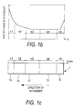
- Fig. 1b is a graph showing the relationship of rate of change of flux density with respect to the position of the movable member in the direction of motion.
- Fig. 1c shows a plan diagram of the permanent magnet.
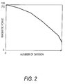
- Fig. 2 is a graph showing the relationship of the ratio of magnetic force and the number of divisions in the permanent magnet.
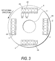
- Fig. 3 is a lateral view showing the rotor of a motor according to a second embodiment of this invention.
- Fig. 4 is a partial schematic view showing a rotor of a motor according to a third embodiment of this invention.
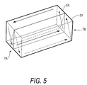
- Fig. 5 shows the route taken by an eddy current in magnet sections on the leading edge of the rotor.
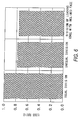
- Fig. 6 is a graph showing eddy current loss in respective aspects of dividing the permanent magnet.
- Fig. 7 is a partial schematic view showing a rotor of a motor according to a fourth embodiment of this invention.
- Fig. 8 is a partial schematic view showing a rotor of a motor according to a fifth embodiment of this invention.
- Fig. 1c shows a permanent magnet 1 provided for the movable member of a permanent magnet electric motor.
- the electric motor may be a rotating motor or a linear motor.
- an alternating current magnetic flux (alternating magnetic field) for driving the movable member applies a repulsive force on the permanent magnet 1. This repulsive force displaces the movable member.
- the permanent magnets 1 are disposed as shown in Fig. 1a, for example.
- This type of motor is known as an interior permanent magnet (IPM) motor in which permanent magnets are located in the core of the rotor (which is a movable member).
- IPM interior permanent magnet
- the alternating current flowing in the stator coils 21 of the stator 20 disposed on the outer periphery of the rotor 2 applies a rotating magnetic flux on the rotor 2 and drives the rotor 2.
- the permanent magnet 1 is divided by substantially flat faces into a plurality of sections 1A-1E, the sections electrically insulated from each other, in order to suppress the flow of eddy current resulting from high frequency components in the alternating magnetic field.
- the dimensions and shape of each section of the permanent magnet are set based on the rate of change in the flux density at positions in each section. Namely, they are set based on the position dependence of the rate of change in the flux density applied to the permanent magnet during fixed speed operation of the rotor 2.
- the rate of change in the flux density is taken as a mean value of magnitude of the time-derivative of the flux density, or the difference between the maximum and minimum of the flux density in a rotational period.
- the permanent magnet 1 is formed by assembling and integrating the magnet sections so that overall they have an elongated rectangular shape.
- the divided magnet sections are connected in series substantially along the direction of the motion of the permanent magnet 1.
- the direction of the motion of the permanent magnet of the rotor is defined as the direction of the speed vector (direction of rotation) at the center of the permanent magnet.
- the permanent magnet 1 is integrated by an adhesive which has an electrically insulating property.
- the graph of Fig. 1b shows schematically the position dependence of the rate of change in the flux density in a longitudinal direction (on the X-axis set on the main surface of the magnet 1 as shown Fig. 1c) during fixed speed operation.
- the longitudinal direction is parallel with the direction of the motion of the permanent magnet 1.
- the relationship of the rate of change in the flux density to the width of the magnet section 1A-1E shows that the width is small in magnet section at a position in which the rate of change in the flux density is large (for example, magnet sections 1A, 1E), as shown in Fig. 1b and 1c.
- the width of the magnet section is wide for magnet sections at positions at which the rate of change in the flux density is small (for example magnet section 1C).
- each section of the permanent magnet is set in response to the rate of change in the flux density applied to that section during fixed-speed operation. In this manner, a particularly large eddy current loss does not occur in any magnet section 1A - 1E. Therefore it is possible to suppress increases in the temperature of the magnet sections and the generation of eddy current loss in the overall permanent magnet 1.
- the permanent magnets 1 are divided in a longitudinal direction (direction of motion) into a magnet section 1A having a width t1, a magnet section 1B having a width t2, a magnet section 1C having a width t3, a magnet section 1D having a width t4, and a magnet section 1E having a width t5.
- the width t1 - t5 of each magnet section 1A - 1E is determined in response to the rate of change of the magnetic flux generated on magnet sections when the motor is driven. To describe this in more detail, the width of the magnet sections 1A-1E may be determined so that the eddy current loss generated in each magnet section1A - 1E is equal.
- Rationalizing the divisions in the permanent magnet 1 in the above manner makes it possible to suppress the generation of eddy currents without unduly increasing the number of divisions in the permanent magnet 1.
- the overall magnetic force of the permanent magnet 1 is not highly reduced by this process of dividing.
- the ratio of magnetic force of the permanent magnet 1 decreases as the number of divisions increases. Therefore, the number of divisions must be minimized in order to maintain the performance of a motor.
- the minimization of the number of divisions is strategically achieved by decreasing the width t1 - t5 of the magnet sections 1A - 1E as the rate of change in the flux density increases. As a result, crucial reductions in motor performance (output and efficiency) can be avoided.
- FIG. 3 shows the width of the magnet section lying in the leading edge of the permanent magnet according to this embodiment.
- the rotor 2 rotating about the rotation shaft 3 comprises a plurality of laminated steel plates which are laminated in the direction of the rotation shaft 3. More precisely, four permanent magnets 4 are disposed at intervals of 90 degrees in proximity to the outer periphery of the rotor 2. Each of the permanent magnets 4 is arranged along a perpendicular direction with respect to a radial direction of the rotor 2.Although the rotating element in this embodiment has permanent magnets with four poles, this is merely exemplary and this invention is not limited with respect to the pole number (or number) of permanent magnets.
- a cylindrical stator (which is similar to the stator 20 of Fig. 1a) is disposed on the outer periphery of the rotor 2 in order to encircle the rotor 2.
- a rotating magnetic flux is generated by supplying an excitation current (for example a three-phase alternating current) to the stator coils of the stator.
- the rotor 2 rotates due to the repulsive force of the permanent magnets 4 against the magnetic flux.
- the method of coiling the coils of the stator coils may be concentrated winding or distributed winding.
- each permanent magnet 4 is set to substantially correspond to the peripheral direction (direction of rotation) of the rotor 2.
- the magnets are divided into a plurality of sections in a longitudinal direction (in other words, direction of rotation).
- the width W1 of the leading magnet section with respect to the direction of rotation is narrower than width of other magnet sections (for example, the width W2 of the magnet section 4C). This is because the rate of change of the flux density displays an increase in leading sections of the permanent magnets 4.
- the width W1 of the leading magnet section 4A is set so that the eddy current generated in the leading magnet 4A is substantially equal to the eddy current generated in other magnet sections. In this manner, the eddy current in the leading magnet section 4A is reduced and as a result, it is possible to suppress the generation of an eddy current in the overall permanent magnet 4.
- FIG. 4 A third embodiment of this invention will be described referring to Fig. 4 in which only one magnet is shown.
- the shape of the magnet section lying at the leading edge of the permanent magnet is determined, taking into account the fact that rate of change in the flux density is high at the leading edge.
- the permanent magnet 5 near the outer periphery of the rotor 2 is divided in almost the same manner as in the second embodiment, only the dividing face 6 between the magnet sections 5A and 5B at the tip is inclined, unlike the second embodiment.
- the magnet section 5A is placed on the leading edge with respect to the direction of rotation of the rotor 2 and the magnet section 5B is adjacent to the magnet section 5A.
- the direction of the dividing face 6 deviates from the direction perpendicular to a longitudinal direction, in contrast to the first and second embodiments.
- the width of the magnet section 5A increases towards the outer periphery of the rotor 2 when viewed from the rotation shaft 3 of the rotor 2. That is to say, the width of the magnet section 5A is wider on the outer peripheral side of the rotor 2 than on the inner peripheral side and the width of the magnet section 5B is narrower on the inner peripheral side of the rotor 2 than on the outer peripheral side.
- This arrangement allows effective decrease in the eddy current loss in the magnet section 5A by reducing the loop of the eddy current flowing therein. In this way, the characteristic increase in the rate of change in the flux density at leading edge with respect to the direction of rotation of the permanent magnet 4 can be compensated for.
- the magnet sections 5X and 5Y when the face separating the magnet sections 5X and 5Y are inclined at an angle from the direction perpendicular to the length of the magnet 5, the magnet sections 5X and 5Y have a shape with a trapezium cross-section as the aforesaid magnets 5A and 5B. Thus it is possible to reduce only the eddy current loop of the magnet section 5A (5X) without increasing the eddy current loop of the magnet section 5B (5Y).
- Fig. 6 shows eddy current loss when the permanent magnet is divided by the same number of sections in order to compare with a conventional example of equal division, an example according to the first and second embodiments of unequal division and an example according to the third embodiment of division by an inclined face.
- the loss ratio undergoes a large reduction when unequal division is used in this invention.
- the loss ratio undergoes even larger reductions when division of the leading edge with an inclined face is used in this invention.
- the permanent magnet 8 is disposed substantially along the outer periphery of the rotor 2.
- the difference of this embodiment from the third embodiment lies in the fact that the dividing face 10 of the other end, between the magnet 8D and the adjacent magnet 8C, also deviates from the perpendicular direction.
- the width of magnet sections 8A, 8D at both ends increases towards the outer periphery of the rotor 2. That is to say, the width of the magnet sections 8A, 8D is wider on the outer peripheral side of the rotor 2 than on the inner peripheral side.
- the permanent magnets 12 are disposed near the outer periphery of the rotor 2 in the same manner as in the third embodiment.
- the permanent magnets 12 are divided into a magnet portion 13 on the outer peripheral side of the rotor 2 (the stator side) and a magnet portion 14 on the inner peripheral side of the rotor 2 (the opposite side to the stator).
- the magnet potion 13 on the outer peripheral side of the rotor is divided into a plurality of magnet sections along its longitudinal direction (which substantially corresponds to the direction of the rotation of the motor 2).
- the width W3 of the magnet section 13A on the leading edge is narrower than the width of the other magnet sections (for example, the width W4 of the magnet section 13C).
- the permanent magnet 1 has a rectangular shape.
- this invention is not limited to this shape and for example, it is possible to apply this invention to permanent magnets having cross sections in the shape of a barrel or in a curved shape or a permanent magnet having another arbitrary shape.
- the rotating motor provided with a rotor on the inner side of the stator.
- this invention may be applied to a rotating electric machine (motor, generator, motor/generator) provided with the rotor on the outer side of the stator or a rotating electric machine provided with the rotor on an inner and outer side of the stator.
- the outer and inner side of the rotor in the above embodiment are switched respectively to the stator side and the side opposite the stator. That is to say, as shown in the fifth embodiment above, when the permanent magnets disposed on the rotor are divided into two portions, they are divided into a plurality of sections on the stator side and not divided into sections on the side opposite the stator.
Abstract
Description
Claims (8)
- A permanent magnet electrical machine used as a motor or as a generator, comprising:wherein the alternating magnetic field applies a repulsive force on the permanent magnet (1; 4; 5; 8; 12), the permanent magnet (1; 4; 5; 8; 12) is divided into a plurality of sections (1A-1E; 4A-4C; 5A-5B; 8A-8D; 13A-13C) in order to suppress the flow of an eddy current generated by high frequency components in the alternating magnetic field, and at least one of the sections (1A-1E; 4A-4C; 5A-5B; 8A-8D; 13A-13C) of the permanent magnet (1; 4; 5; 8; 12) has the shape and dimensions which are determined, taking account of the position dependence of the rate of change in the flux density applied to the permanent magnet (1; 4; 5; 8; 12) during fixed-speed operation of the movable member (2).a movable member (2) having a permanent magnet (1; 4; 5; 8; 12), and a stator (20) having a coil (21) which generates an alternating magnetic field to drive the movable member (2),
- The permanent magnet electrical machine as defined in Claim 1, wherein the permanent magnet (1) is divided with the substantially flat faces which are substantially perpendicular to the direction of motion of the permanent magnet (1), the width of each section (1A-1E) of the permanent magnet (1) is set in response to the rate of change in the flux density at each position of the sections (1A-1E) during fixed-speed operation.
- The permanent magnet electrical machine as defined in Claim 2, wherein the width of each section (1A-1E) of the permanent magnet (1) is set to decrease as the rate of change in the flux density in that section increases.
- The permanent magnet electrical machine as defined in Claim 2 or Claim 3, wherein the width of each section (1A-1E) of the permanent magnet (1) is set so that eddy current loss in each section (1A-1E) of the permanent magnet (1) is substantially equal.
- The permanent magnet electrical machine as defined in any one of Claim 2 or Claim 4, wherein the movable member (2) is a rotating element, and the permanent magnet is divided into a plurality of sections along the direction of rotation of the rotating element.
- The permanent magnet electrical machine as defined in Claim 1, wherein the movable member (2) is a rotating element, and the permanent magnet (4) is divided into a plurality of sections (4A-4C) with respect to the direction of rotation of the rotating element in order to suppress the flow of eddy current, the width of the section (4A) placed on the leading edge in the direction of rotation of the rotating element are more narrow than the width of other sections (4C).
- The permanent magnet electrical machine as defined in Claim 6, wherein the permanent magnet (12) is divided into a plurality of portions (13, 14) in a radial direction of the rotating element (2), and at least the potion (13) of the magnet nearest the stator is divided with respect to the direction of rotation of the rotating element.
- The permanent magnet electrical machine as defined in Claim 1, wherein the movable member (2) is a rotating element, and the permanent magnet (5) is divided into a plurality of sections (5A-5B) with respect to the direction of rotation of the rotating element, and the section (5A) of the permanent magnet (5) positioned on the leading edge is of a width that increases towards the outer peripheral side of the rotating element (2) in order to reduce the loop of eddy current.
Applications Claiming Priority (2)
| Application Number | Priority Date | Filing Date | Title |
|---|---|---|---|
| JP2001058116 | 2001-03-02 | ||
| JP2001058116A JP3707539B2 (en) | 2001-03-02 | 2001-03-02 | Electric motor or generator |
Publications (3)
| Publication Number | Publication Date |
|---|---|
| EP1237253A2 true EP1237253A2 (en) | 2002-09-04 |
| EP1237253A3 EP1237253A3 (en) | 2005-10-19 |
| EP1237253B1 EP1237253B1 (en) | 2008-06-25 |
Family
ID=18917894
Family Applications (1)
| Application Number | Title | Priority Date | Filing Date |
|---|---|---|---|
| EP02001612A Expired - Lifetime EP1237253B1 (en) | 2001-03-02 | 2002-01-23 | Motor or generator |
Country Status (4)
| Country | Link |
|---|---|
| US (1) | US6703743B2 (en) |
| EP (1) | EP1237253B1 (en) |
| JP (1) | JP3707539B2 (en) |
| DE (1) | DE60227209D1 (en) |
Cited By (5)
| Publication number | Priority date | Publication date | Assignee | Title |
|---|---|---|---|---|
| WO2006003244A2 (en) * | 2004-07-02 | 2006-01-12 | Abb Oy | Permanent-magnet rotor and a method for manufacturing a permanent-magnet rotor |
| DE102005019368A1 (en) * | 2005-04-26 | 2006-11-09 | Siemens Ag | Permanent magnet rotor design for electric machine, has permanent magnets arranged radially over one another in recesses |
| WO2008142519A1 (en) * | 2007-05-23 | 2008-11-27 | Toyota Jidosha Kabushiki Kaisha | Permanent magnet-type rotary electric machine and production method for rotor for permanent magnet-type rotary electric machine |
| WO2011026600A3 (en) * | 2009-09-04 | 2011-08-11 | Bombardier Transportation Gmbh | Electric machine and method for producing the same |
| EP3355442A4 (en) * | 2015-09-25 | 2019-06-12 | Nitto Denko Corporation | Permanent magnet unit, rotating machine having permanent magnet unit, and method for manufacturing permanent magnet unit |
Families Citing this family (31)
| Publication number | Priority date | Publication date | Assignee | Title |
|---|---|---|---|---|
| CA2441746C (en) * | 2001-03-14 | 2010-06-29 | Akira Hosaka | Magnetic motor |
| US7233088B2 (en) * | 2003-01-17 | 2007-06-19 | Magnetic Torque International, Ltd. | Torque converter and system using the same |
| US7268454B2 (en) * | 2003-01-17 | 2007-09-11 | Magnetic Torque International, Ltd. | Power generating systems |
| JP4536339B2 (en) * | 2003-08-26 | 2010-09-01 | 延江 湊 | Direct drive magnetic rotating device |
| JP4572647B2 (en) * | 2004-10-01 | 2010-11-04 | 株式会社日立製作所 | Permanent magnet rotating electrical machine and wind power generation system |
| US7808142B2 (en) * | 2004-10-27 | 2010-10-05 | E3 Solutions, Llc | Multivariable generator and method of using the same |
| US20060111191A1 (en) * | 2004-11-19 | 2006-05-25 | Magnetic Torque International | Torque transfer system and method of using the same |
| JP4581770B2 (en) * | 2005-03-17 | 2010-11-17 | トヨタ自動車株式会社 | COMPOUND MAGNET, MOTOR, AND MANUFACTURING METHOD |
| US7504754B2 (en) * | 2005-10-31 | 2009-03-17 | Caterpillar Inc. | Rotor having multiple permanent-magnet pieces in a cavity |
| EP1786085B1 (en) * | 2005-11-15 | 2016-08-03 | Shin-Etsu Chemical Co., Ltd. | Permanent magnet rotating electric machine |
| JP4270203B2 (en) * | 2005-12-21 | 2009-05-27 | ダイキン工業株式会社 | Motor and compressor |
| DE102006004537A1 (en) * | 2006-02-01 | 2007-08-02 | Volkswagen Ag | Electrical machine based on permanent magnetic rotor or stator, is made from assembly of individual magnetic segments separated by insulation |
| US7385328B2 (en) * | 2006-05-23 | 2008-06-10 | Reliance Electric Technologies, Llc | Cogging reduction in permanent magnet machines |
| US8040009B2 (en) * | 2007-03-15 | 2011-10-18 | Daikin Industries, Ltd. | Filed element |
| JP4466681B2 (en) * | 2007-05-11 | 2010-05-26 | トヨタ自動車株式会社 | Rotating electric machine rotor and rotating electric machine |
| US7847461B2 (en) * | 2007-06-06 | 2010-12-07 | Gm Global Technology Operations, Inc. | Multi-layer magnet arrangement in a permanent magnet machine for a motorized vehicle |
| EP2304863B1 (en) * | 2008-07-30 | 2018-06-27 | Regal Beloit America, Inc. | Interior permanent magnet motor including rotor with unequal poles |
| GB0901122D0 (en) * | 2009-01-26 | 2009-03-11 | Marquis Guillaume | Magnetic amplifier |
| US8222787B2 (en) * | 2009-04-01 | 2012-07-17 | General Electric Company | Electric machine |
| JPWO2010150362A1 (en) * | 2009-06-24 | 2012-12-06 | トヨタ自動車株式会社 | Sintered magnet and manufacturing method thereof |
| US9577503B2 (en) * | 2010-05-03 | 2017-02-21 | The Board Of Regents Of The University Of Texas System | Rotating machines using trapped field magnets and related methods |
| CN102754307B (en) * | 2011-02-02 | 2015-05-06 | 丰田自动车株式会社 | Permanent magnet, motor rotor or stator, dynamo-electric machine |
| EP2515417B1 (en) * | 2011-04-18 | 2014-04-02 | Siemens Aktiengesellschaft | A synchronous permanent magnet machine |
| JP5304837B2 (en) * | 2011-04-26 | 2013-10-02 | 株式会社安川電機 | Rotating electric machine and rotor |
| US10141805B2 (en) | 2012-08-27 | 2018-11-27 | Albus Technologies Ltd. | Planar stator with efficient use of space |
| US9641054B2 (en) * | 2013-05-17 | 2017-05-02 | General Electric Company | Segmented magnet component for electric machine and method of assembly |
| KR101534706B1 (en) * | 2013-12-18 | 2015-07-07 | 현대자동차 주식회사 | Interior permanent magnet synchronous motor |
| JP6359480B2 (en) * | 2015-04-14 | 2018-07-18 | 株式会社神戸製鋼所 | Rotor for axial gap type permanent magnet rotating machine and axial gap type permanent magnet rotating machine |
| JP2018164378A (en) * | 2017-03-27 | 2018-10-18 | 本田技研工業株式会社 | Ipm rotor magnet, and method of manufacturing ipm rotor and ipm rotor magnet |
| JP7132729B2 (en) | 2018-03-12 | 2022-09-07 | 株式会社デンソー | Rotating electric machine |
| JP2021166456A (en) * | 2020-04-08 | 2021-10-14 | 日立Astemo株式会社 | Rotor and rotary electric machine |
Citations (5)
| Publication number | Priority date | Publication date | Assignee | Title |
|---|---|---|---|---|
| US5191256A (en) * | 1989-12-15 | 1993-03-02 | American Motion Systems | Interior magnet rotary machine |
| JPH114555A (en) * | 1997-06-11 | 1999-01-06 | Hitachi Ltd | Permanent magnet rotating machine |
| JPH11252833A (en) * | 1998-03-05 | 1999-09-17 | Honda Motor Co Ltd | Permanent magnet type motor |
| JP2000228838A (en) * | 1998-12-01 | 2000-08-15 | Toyota Motor Corp | Permanent magnet motor |
| JP2001025189A (en) * | 1999-07-09 | 2001-01-26 | Toyota Motor Corp | Permanent magnet of permanent magnet rotor |
Family Cites Families (6)
| Publication number | Priority date | Publication date | Assignee | Title |
|---|---|---|---|---|
| EP0746079B1 (en) * | 1995-05-31 | 2003-08-13 | Matsushita Electric Industrial Co., Ltd. | Motor with built-in permanent magnets |
| KR100263445B1 (en) * | 1997-11-13 | 2000-08-01 | 윤종용 | Rotor for brushless dc motor |
| JPH11285183A (en) * | 1998-03-26 | 1999-10-15 | Fanuc Ltd | Rotor structure of synchronous motor |
| JP4089072B2 (en) * | 1998-10-23 | 2008-05-21 | 三菱電機株式会社 | Permanent magnet embedded motor |
| DE69928363T2 (en) * | 1998-12-25 | 2006-06-01 | Matsushita Electric Industrial Co., Ltd., Kadoma | Motor with embedded permanent magnets embedded in the rotor |
| JP2000245085A (en) * | 1998-12-25 | 2000-09-08 | Matsushita Electric Ind Co Ltd | Motor |
-
2001
- 2001-03-02 JP JP2001058116A patent/JP3707539B2/en not_active Expired - Fee Related
-
2002
- 2002-01-23 DE DE60227209T patent/DE60227209D1/en not_active Expired - Lifetime
- 2002-01-23 EP EP02001612A patent/EP1237253B1/en not_active Expired - Lifetime
- 2002-02-12 US US10/072,912 patent/US6703743B2/en not_active Expired - Fee Related
Patent Citations (5)
| Publication number | Priority date | Publication date | Assignee | Title |
|---|---|---|---|---|
| US5191256A (en) * | 1989-12-15 | 1993-03-02 | American Motion Systems | Interior magnet rotary machine |
| JPH114555A (en) * | 1997-06-11 | 1999-01-06 | Hitachi Ltd | Permanent magnet rotating machine |
| JPH11252833A (en) * | 1998-03-05 | 1999-09-17 | Honda Motor Co Ltd | Permanent magnet type motor |
| JP2000228838A (en) * | 1998-12-01 | 2000-08-15 | Toyota Motor Corp | Permanent magnet motor |
| JP2001025189A (en) * | 1999-07-09 | 2001-01-26 | Toyota Motor Corp | Permanent magnet of permanent magnet rotor |
Cited By (8)
| Publication number | Priority date | Publication date | Assignee | Title |
|---|---|---|---|---|
| WO2006003244A2 (en) * | 2004-07-02 | 2006-01-12 | Abb Oy | Permanent-magnet rotor and a method for manufacturing a permanent-magnet rotor |
| WO2006003244A3 (en) * | 2004-07-02 | 2006-04-13 | Abb Oy | Permanent-magnet rotor and a method for manufacturing a permanent-magnet rotor |
| DE102005019368A1 (en) * | 2005-04-26 | 2006-11-09 | Siemens Ag | Permanent magnet rotor design for electric machine, has permanent magnets arranged radially over one another in recesses |
| WO2008142519A1 (en) * | 2007-05-23 | 2008-11-27 | Toyota Jidosha Kabushiki Kaisha | Permanent magnet-type rotary electric machine and production method for rotor for permanent magnet-type rotary electric machine |
| US7973442B2 (en) | 2007-05-23 | 2011-07-05 | Toyota Jidosha Kabushiki Kaisha | Permanent magnet-type rotary electric machine and production method for rotor for permanent magnet-type rotary electric machine |
| WO2011026600A3 (en) * | 2009-09-04 | 2011-08-11 | Bombardier Transportation Gmbh | Electric machine and method for producing the same |
| EP3355442A4 (en) * | 2015-09-25 | 2019-06-12 | Nitto Denko Corporation | Permanent magnet unit, rotating machine having permanent magnet unit, and method for manufacturing permanent magnet unit |
| US10629348B2 (en) | 2015-09-25 | 2020-04-21 | Nitto Denko Corporation | Permanent magnet unit, rotating machine having permanent magnet unit, and method for manufacturing permanent magnet unit |
Also Published As
| Publication number | Publication date |
|---|---|
| DE60227209D1 (en) | 2008-08-07 |
| EP1237253B1 (en) | 2008-06-25 |
| JP3707539B2 (en) | 2005-10-19 |
| US20020121827A1 (en) | 2002-09-05 |
| EP1237253A3 (en) | 2005-10-19 |
| JP2002262490A (en) | 2002-09-13 |
| US6703743B2 (en) | 2004-03-09 |
Similar Documents
| Publication | Publication Date | Title |
|---|---|---|
| EP1237253B1 (en) | Motor or generator | |
| US9553496B2 (en) | Low-inertia direct drive having high power density | |
| EP0620634B1 (en) | Hybrid excitation type permanent magnet synchronous motor | |
| KR100373226B1 (en) | Reluctance motor and compressor-driving reluctance motor | |
| US7902712B2 (en) | Magnetic member, rotor, motor, compressor, blower, air conditioner and vehicle-mounted air conditioner | |
| US20090160392A1 (en) | Virtual Moving Air Gap For An Axial Flux Permanent Magnet Motor With Dual Stators | |
| US20140252910A1 (en) | Induction machine | |
| EP1253701B1 (en) | Motor | |
| EP1643618B1 (en) | Rotor for rotary electric machine | |
| JP3452434B2 (en) | Permanent magnet rotor | |
| EP0909009A1 (en) | Brushless DC motor using permanent magnet | |
| US5418414A (en) | Electric motor with permanent-magnet excitation | |
| JP2003032978A (en) | Dynamo-electric machine | |
| US20070200446A1 (en) | Electrical machine | |
| US20210359566A1 (en) | Stator and motor using same | |
| Njeh et al. | 3D FEA based investigation of the cogging torque of a claw pole transverse flux permanent magnet machine | |
| JPH09308198A (en) | Permanent magnet motor | |
| CN114982095A (en) | Stator and rotating electric machine using the same | |
| JP2002186244A (en) | Permanent magnet linear motor | |
| US4435664A (en) | Magnetic interpole apparatus for improving commutation characteristics of a dynamoelectric machine | |
| US7388309B2 (en) | Magnetic circuit structure for rotary electric machine | |
| JP2016129447A (en) | Rotary electric machine | |
| JP2007166798A (en) | Dynamo-electric machine, compressor, blower, and air conditioner | |
| JPH09224338A (en) | Motor | |
| WO2023080110A1 (en) | Magnetic geared motor and manufacturing method of magnetic geared motor |
Legal Events
| Date | Code | Title | Description |
|---|---|---|---|
| PUAI | Public reference made under article 153(3) epc to a published international application that has entered the european phase |
Free format text: ORIGINAL CODE: 0009012 |
|
| 17P | Request for examination filed |
Effective date: 20020123 |
|
| AK | Designated contracting states |
Kind code of ref document: A2 Designated state(s): AT BE CH CY DE DK ES FI FR GB GR IE IT LI LU MC NL PT SE TR |
|
| AX | Request for extension of the european patent |
Free format text: AL;LT;LV;MK;RO;SI |
|
| RIN1 | Information on inventor provided before grant (corrected) |
Inventor name: KIKUCHI, TOSHIO Inventor name: KITADA, SHINICHIRO Inventor name: TSUNEYOSHI, TAKASHI Inventor name: KANEKO, YUTARO |
|
| PUAL | Search report despatched |
Free format text: ORIGINAL CODE: 0009013 |
|
| AK | Designated contracting states |
Kind code of ref document: A3 Designated state(s): AT BE CH CY DE DK ES FI FR GB GR IE IT LI LU MC NL PT SE TR |
|
| AX | Request for extension of the european patent |
Extension state: AL LT LV MK RO SI |
|
| AKX | Designation fees paid |
Designated state(s): DE FR GB |
|
| 17Q | First examination report despatched |
Effective date: 20070330 |
|
| GRAP | Despatch of communication of intention to grant a patent |
Free format text: ORIGINAL CODE: EPIDOSNIGR1 |
|
| GRAS | Grant fee paid |
Free format text: ORIGINAL CODE: EPIDOSNIGR3 |
|
| GRAA | (expected) grant |
Free format text: ORIGINAL CODE: 0009210 |
|
| AK | Designated contracting states |
Kind code of ref document: B1 Designated state(s): DE FR GB |
|
| REG | Reference to a national code |
Ref country code: GB Ref legal event code: FG4D |
|
| REF | Corresponds to: |
Ref document number: 60227209 Country of ref document: DE Date of ref document: 20080807 Kind code of ref document: P |
|
| PLBE | No opposition filed within time limit |
Free format text: ORIGINAL CODE: 0009261 |
|
| STAA | Information on the status of an ep patent application or granted ep patent |
Free format text: STATUS: NO OPPOSITION FILED WITHIN TIME LIMIT |
|
| 26N | No opposition filed |
Effective date: 20090326 |
|
| PGFP | Annual fee paid to national office [announced via postgrant information from national office to epo] |
Ref country code: DE Payment date: 20140115 Year of fee payment: 13 |
|
| PGFP | Annual fee paid to national office [announced via postgrant information from national office to epo] |
Ref country code: FR Payment date: 20140108 Year of fee payment: 13 |
|
| PGFP | Annual fee paid to national office [announced via postgrant information from national office to epo] |
Ref country code: GB Payment date: 20140122 Year of fee payment: 13 |
|
| REG | Reference to a national code |
Ref country code: DE Ref legal event code: R119 Ref document number: 60227209 Country of ref document: DE |
|
| GBPC | Gb: european patent ceased through non-payment of renewal fee |
Effective date: 20150123 |
|
| PG25 | Lapsed in a contracting state [announced via postgrant information from national office to epo] |
Ref country code: DE Free format text: LAPSE BECAUSE OF NON-PAYMENT OF DUE FEES Effective date: 20150801 Ref country code: GB Free format text: LAPSE BECAUSE OF NON-PAYMENT OF DUE FEES Effective date: 20150123 |
|
| REG | Reference to a national code |
Ref country code: FR Ref legal event code: ST Effective date: 20150930 |
|
| PG25 | Lapsed in a contracting state [announced via postgrant information from national office to epo] |
Ref country code: FR Free format text: LAPSE BECAUSE OF NON-PAYMENT OF DUE FEES Effective date: 20150202 |