EP1236432A2 - Perimeter - Google Patents
Perimeter Download PDFInfo
- Publication number
- EP1236432A2 EP1236432A2 EP02251385A EP02251385A EP1236432A2 EP 1236432 A2 EP1236432 A2 EP 1236432A2 EP 02251385 A EP02251385 A EP 02251385A EP 02251385 A EP02251385 A EP 02251385A EP 1236432 A2 EP1236432 A2 EP 1236432A2
- Authority
- EP
- European Patent Office
- Prior art keywords
- perimeter
- input
- control
- target spot
- target
- Prior art date
- Legal status (The legal status is an assumption and is not a legal conclusion. Google has not performed a legal analysis and makes no representation as to the accuracy of the status listed.)
- Ceased
Links
Images


Classifications
-
- A—HUMAN NECESSITIES
- A61—MEDICAL OR VETERINARY SCIENCE; HYGIENE
- A61B—DIAGNOSIS; SURGERY; IDENTIFICATION
- A61B3/00—Apparatus for testing the eyes; Instruments for examining the eyes
- A61B3/02—Subjective types, i.e. testing apparatus requiring the active assistance of the patient
- A61B3/024—Subjective types, i.e. testing apparatus requiring the active assistance of the patient for determining the visual field, e.g. perimeter types
Definitions
- This invention relates to a perimeter, and more particularly a perimeter that projects a target spot onto the inside surface of a visual field dome and records the position of the projected target spot and patient's responses relating to the visual recognition thereof.
- Measuring a patient's visual field is an effective way of diagnosing some eye ailments.
- the Goldmann perimeter is extensively employed for such measurements.
- a target spot is projected onto a hemispherical visual field dome of the perimeter, and an examiner manually adjusts the projection position of the spot by a means of a purely mechanical mechanism.
- the responses of the patient to the target spot are then recorded on a chart.
- the target projection mechanism is controlled in accordance with a predetermined program, or multiple LEDs or other such light sources are disposed which are lit in accordance with the program, and the patient operates a response button when given a suitable prompt.
- Figures 4 and 5 show the arrangement for a conventional manual Goldmann perimeter.
- reference numeral 202 shows a visual field dome, in front of which a patient chin-rest 203 is positioned at the dome center. Over the dome 202 is a light source 211.
- a projector 212 is used to project a target spot from the light source 211 at any point on the inside surface of the dome 202, and the patient's responses to the targets are recorded on a chart.
- the patient responds by pressing a push-button 213, which is located on the stand used to support the dome 202.
- Figure 5 is a rear view of the perimeter.
- a telescope 204 that is used to align the patient's eye with the perimeter and to monitor the examination sequences.
- the projector 212 is operated by a mechanical linkage comprising a pantograph 210a connected to the projector.
- a handle 210 At the end of the pantograph 210a, there is a handle 210.
- a pen attached to the handle 210 records the positions of the target spot and the positions of the patient's responses on a printed paper 206 that is mounted at the back of the perimeter.
- An appropriate chart for isoptometry is printed on the recording pager for each system employed.
- the target spot is operated and recorded by purely mechanical means in the case of a manual Goldmann perimeter, the measurement and recording operations require skill and experience. Moreover, during the examination the posture of the examiner is constrained, imposing a considerable burden on the examiner.
- a perimeter that projects a target spot onto the inside surface of a visual field dome and records the position of the projected target spot and patient's responses relating to the visual recognition thereof, comprising an optical projection system for projecting the target spot on the inside surface of the visual field dome; control means for electronically controlling a position at which the target spot is projected; input means used for entry of control information for control of the projection position of the target spot by the control means and for recording of response information relating to the patient's response; and display means for displaying the control information and response information supplied via the input means, said display means being adapted for use as an input surface for entry of the control and response information by the input means.
- the arrangement of a conventional Goldmann perimeter is used as the basis for the perimeter of the present invention, which is implemented as a semi-automatic perimeter that is as easy to use as an automated perimeter and enables measurements to be performed with flexibility and efficiency. This is accomplished by applying an electronic system to the operation of the Goldmann perimeter and using the electronic implementation to simulate the operational feel of a prior-art manual (mechanical) Goldmann perimeter.
- Figure 1 shows the structure of the perimeter of the invention.
- reference numeral 18 indicates a visual field dome.
- the eye being examined is aligned with the center of the visual field dome 18 by means of a base and alignment mechanism (not shown).
- Background illumination lamps 16 are provided inside the visual field dome 18.
- the patient is told to look at a target 19 projected onto the inside surface of visual field dome 18.
- the patient visually recognizes the target 19, he responds for the examiner by operating a response switch 17, or by giving a vocal response, or by any other suitable means.
- an optical projection system comprising parts 1 to 15 is used to project the target 19.
- the optical system can, for example, be disposed inside the type of projector arm shown in Figures 4 and 5.
- Reference numeral 2 denotes a target projection lamp, behind which there is a reflecting mirror 1.
- Light from the lamp 2 passes through a condenser lens 3, a target plate 4 and turret filters 5 to 7, and falls incident on a relay lens 8.
- the target plate 4 is used to set the size of the target.
- the target plate 4 is provided with a plurality of apertures, with the desired aperture being moved into the optical axis under the control of a CPU 101.
- filter 5 is a color filter that selects the target color
- filters 6 and 7 are two different types of ND filter used to regulate the amount of light.
- the light passes through a focusing lens 9 and a shutter 10 (aperture), deflected by a mirror 11, and the light passes through a relay lens 12 and is reflected by a mirror 13.
- two mirrors, 14A and 14B are provided to control the positioning of the projected target.
- a drive means such as a motor (not shown) is used to rotate each mirror under the control of the CPU 101.
- the target is projected from a projector lens 15 onto the projection surface of the visual field dome 18.
- the perimeter of this embodiment can be used as an automatic perimeter by controlling the target projection mechanism (1 to 15) under the control of the CPU 101 in accordance with the predetermined program, and visual field measurement can also be performed manually. That is, by applying operating means such as a display, mouse, tablet and the like to the operation system of a manual Goldmann perimeter, the manual operation system was implemented electronically.
- the control system of the perimeter of the invention was arranged as follows.
- the CPU 101 is connected to a display monitor 102 such as a CRT or liquid crystal display, an external storage unit 103 that uses floppy disks or MO media or the like, a printer 104, and so forth. Via an I/O interface 106, the system is also provided with an input device or devices such as a mouse 107, a suitable pointing device 109, and a light-pen 108 used with the monitor 102.
- a display monitor 102 such as a CRT or liquid crystal display
- an external storage unit 103 that uses floppy disks or MO media or the like
- printer 104 printer 104
- an input device or devices such as a mouse 107, a suitable pointing device 109, and a light-pen 108 used with the monitor 102.
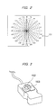
- the pointing device 109 can be a slide-pad operated by finger or special stylus, or a digitizer device as shown in Figure 3.
- the digitizer device of Figure 3 can be used on a digitizer pad on which is printed (or displayed) a conventional Goldmann perimeter recording chart pattern.
- a positioning aperture 152 can be used to check the position on the digitizer pad, and a click button 153 is used for command entry when the target spot position is determined or when the patient's responses are to be recorded.
- the current position of the pointing device 109 on the digitizer pad is output as coordinate data with the aid of coordinate detection systems such as mechanical, ball-based or optical systems.
- Mouse, light-pen and pointing device systems are each used for coordinate entry, and it is not necessary to provide all of these devices.
- the examiner only needs to be provided with an operating feel that is as close as possible to that provided by using a recording chart with a conventional mechanical Goldmann perimeter.
- the target projection mechanism (1 to 15) is controlled via an interface and drive means such as motors and solenoids (not shown) under the control of the CPU 101 according to a predetermined program. This is the same as in the prior art, and further description thereof is therefore omitted.
- the angles of the mirrors 14A and 14B are not adjusted by the examiner via a mechanical linkage, as in a conventional manual Goldmann perimeter. Instead, the light-pen 108 or pointing device 109 is used to make an indication on the recording chart pattern displayed on the monitor 102. If the mouse 107 or light-pen 108 is used as the input device, it produces coordinate signals on the basis of which a pointer is displayed on the monitor 102 to show the operation position. This enables the device button to be operated for command implementation. In the case of the digitizer device of Figure 3, it is possible to use an arrangement in which the monitor 102 is used for display, and one in which the chart pattern is printed on the digitizer pad or shown on a display laid on the digitizer pad.
- the chart pattern displayed on the monitor 102 is a recording chart pattern such as isoptometry suitable for any kind of perimetry system.
- a pattern 151 shown in Figure 2 is an example.
- the pattern corresponds to the target projection surface of the visual field dome 18.
- the examiner uses the light-pen 108 or other input device for position entry on the pattern to control the projection position for the target spot and to record the patient's response position.
- a suitable control system can be used to switch between inputting the target spot projection position and inputting the patient's response position.
- a keyboard or foot-switch (not shown) can be used to switch between projection position input mode and response position input mode.
- the CPU 101 controls the target projection mechanism (1 to 15) and the target projection positioning.
- Figure 6 shows a flow chart of an examination sequence in the case of a perimeter according to the present invention used as a (semi-) manual perimeter.
- a touch-panel is provided on the monitor 102 to input the coordinate data.
- the mouse 107, light-pen 108 and pointing device 109 are not used, but can be readily replaced by the touch-panel in the following control operation.
- step S1 when the power is switched on, the motors are initialized in step S1. These are the motors used to drive the components such as the mirrors 14A and 14B for controlling the vertical and horizontal projection directions and the projector lens 15.
- step S2 X and Y axes and scales are displayed on the monitor 102.
- the chart pattern of Figure 2 can be used for this with the positions on the display and the touch-panel input coordinate system being associated beforehand with the actual visual field dome coordinate system.
- step S3 the system waits for input via the touch-panel on the monitor 102.
- touch-panel input is received, the input coordinates are detected and the motors are energized in step S4 to project the target at the position thus input.
- the projection mechanism (1 to 15) is then controlled in step S5 to project the target spot at the coordinate position input on the touch-panel by the examiner.
- step S6 the system enters a loop in which the target is projected at a plurality of points and the responses by the patient are input.
- step S6 the touch-panel input is monitored to determine whether or not the input position has changed. If the input position has changed, the motors are energized in step S7 to project the target at the input position, as is the same with step S4.
- the examiner while examining the patient, provides the patient with prompts, moving the target and requesting the patient to respond by using the response switch 17.
- step S8 it is determined whether or not there has been a patient input from the response switch 17. If there has been an input, the process moves to step S11. If there is no input, the process moves to step S9. In step S9, it is determined whether or not input via the touch-panel has stopped (that is, whether the examiner's finger or input stylus is off the touch-panel). If input has stopped, the target display is turned off in step S10 and the process goes back to step S3.
- step S11 If there is a patient response, the process moves from step S8 to step S11, and the response is plotted on the screen of the monitor 102. Each such plot point corresponds to the target projection coordinates at the time of response switch operation. In addition to being plotted on-screen, the coordinate data corresponding to the response point are stored in memory for subsequent output processing and the like.
- step S12 it is determined whether or not the examination has been finished. This can be done by, for example, determining the state of a Finish switch (not shown). If the examination is not finished, the process reverts to step S3, and the process of projecting and moving the target and recording responses is repeated.
- an appropriate output process is effected via the monitor 102 in step S13.
- a plurality of response positions can be connected on the monitor 102 to display a graph of the visual field range.
- the response position data can be displayed graphically on the monitor 102 in conformation with the examination system concerned by subjecting the data to computation appropriate for the examination system.
- examination results are printed out by the printer 104.
- the output can be in the form of the screen dump in step S13, or can be in the form of a graph or table of target spot control and response positions.
- the external storage unit 103 is used to store the examination data in a specified format.
- the examiner just tracks the display on the monitor 102 using the touch-panel to readily set each of the target positions and obtain the patient's response at each point.
- Examination results are plotted on-screen and printed out automatically, freeing the examiner of the complex and onerous tasks of recording data on a chart, controlling the target positioning and plotting response positions that are required in the case of a conventional manual Goldmann perimeter.
- Patient prompts can be done arbitrarily, so that the examiner can use his own expertise and experience to decide the target projection sequence and positioning in accordance with the condition and state of the disease concerned, making it possible to expeditiously complete a full and proper examination.
- a perimeter according to the present invention can be used to project the target spot at the desired positions more easily than in the case of a conventional manual Goldmann perimeter in which the target spot position is controlled mechanically.
- the ability to concentrate the operating system in the touch-panel and monitor 102 and light-pen 108 (or the mouse 107 or pointing device 109 and the like) input devices makes it easy to operate during the examination procedure.
- Operation is further facilitated by displaying the operation status on the monitor 102.
- the current target projection position determined using the light-pen 108 (or mouse 107 or pointing device 109) can be displayed on the monitor 102 within the range of visual field that is shown in the form of a concentric recording chart pattern.
- the response switch 17 When the response switch 17 is operated to signify a patient response, the position of the target spot at the time of the response can be acquired as a measurement result, and the response position can be displayed in a different color than the target projection position. It is also possible to automatically record the target spot position at the time of the response by the response switch or a spoken response by the patient.
- the light-pen 108 or the like information relating to visual field measurement can be input in the form of handwritten characters. Handwritten input and character recognition of handwritten character input are known technologies, so further description thereof will be omitted. Also, menus required to control the operating modes of devices involved in visual field measurement can be displayed on the monitor 102 (or a digitizer pad or touch-panel or the like), enabling the examiner to use the light-pen 108 to make selections on the menus.
- measurement points and procedures can also be readily changed to match the needs of the patient or the condition of the patient's eye.
- This makes it possible to complete an examination with speed and efficiency, and, as compared to a conventional mechanical Goldmann perimeter, makes the examination less onerous and tiring for the examiner as well as the patient.
- This is accomplished by applying an electronic system to the operation of the Goldmann perimeter and using the electronic implementation to simulate the operational feel of a conventional manual (mechanical) Goldmann perimeter. This makes the perimeter as easy to use as an automatic perimeter, and enables examinations to be performed with good adaptability and efficiency.
- the target projection mechanism (1 to 15) is not controlled by purely mechanical means; instead, the perimeter can utilize the target projection mechanism of an automatic perimeter, making it possible easily and at a low cost to configure as both an automatic perimeter and as a manual (semi-automatic) perimeter.
- the perimeter according to the present invention that projects a target spot onto the inside surface of a visual field dome and records the position of the projected target spot and patient's responses relating to the visual recognition thereof, comprises an optical projection system for projecting the target spot on the inside surface of the visual field dome; control means for electronically controlling a position at which the target spot is projected; input means used for entry of control information for control of the projection position of the target spot by the control means and for recording of response information relating to the patient's response; and display means for displaying the control information and response information supplied via the input means, said display means being adapted for use as an input surface for entry of the control and response information by the input means.
- electronics is used to simulate the feel of a conventional manual (mechanical) Goldmann perimeter, making the perimeter as easy to use as an automatic perimeter, and enabling examinations to be performed with good adaptability and efficiency.
Abstract
Description
- This invention relates to a perimeter, and more particularly a perimeter that projects a target spot onto the inside surface of a visual field dome and records the position of the projected target spot and patient's responses relating to the visual recognition thereof.
- Measuring a patient's visual field is an effective way of diagnosing some eye ailments. The Goldmann perimeter is extensively employed for such measurements. In a conventional Goldmann perimeter, a target spot is projected onto a hemispherical visual field dome of the perimeter, and an examiner manually adjusts the projection position of the spot by a means of a purely mechanical mechanism. The responses of the patient to the target spot are then recorded on a chart.
- In addition to manual Goldmann perimeters, in recent years there has come into use automatic perimeters in which the control of the target is automated. In an automatic perimeter, the target projection mechanism is controlled in accordance with a predetermined program, or multiple LEDs or other such light sources are disposed which are lit in accordance with the program, and the patient operates a response button when given a suitable prompt.
- A factor behind the emergence of the automated perimeter was that manual perimeters were difficult to use because the target had to be operated manually.
- Figures 4 and 5 show the arrangement for a conventional manual Goldmann perimeter. In Figures 4 and 5,
reference numeral 202 shows a visual field dome, in front of which a patient chin-rest 203 is positioned at the dome center. Over thedome 202 is alight source 211. To examine a patient's visual field, aprojector 212 is used to project a target spot from thelight source 211 at any point on the inside surface of thedome 202, and the patient's responses to the targets are recorded on a chart. The patient responds by pressing a push-button 213, which is located on the stand used to support thedome 202. - Figure 5 is a rear view of the perimeter. As shown, at the center of the
dome 202 there is atelescope 204 that is used to align the patient's eye with the perimeter and to monitor the examination sequences. Theprojector 212 is operated by a mechanical linkage comprising apantograph 210a connected to the projector. At the end of thepantograph 210a, there is ahandle 210. During the examination, a pen attached to thehandle 210 records the positions of the target spot and the positions of the patient's responses on a printedpaper 206 that is mounted at the back of the perimeter. An appropriate chart for isoptometry is printed on the recording pager for each system employed. - Because the target spot is operated and recorded by purely mechanical means in the case of a manual Goldmann perimeter, the measurement and recording operations require skill and experience. Moreover, during the examination the posture of the examiner is constrained, imposing a considerable burden on the examiner.
- In an automatic perimeter the control of the target movement is automated according to a program. Although this simplifies the measurement operation, the use of a preprogrammed measurement sequence makes it impossible to change the measurement points to match a patient's particular situation, making it impossible to perform measurements with good efficiency. Another problem is the length of time it takes to perform the measurements. Manual Goldmann perimeters do not have the above problems of the automated perimeter, so the Goldmann perimeter had some advantages that were worth looking at.
- It is therefore an object of the invention to solve such problems and provide a perimeter that has the advantages of both a manual Goldmann perimeter and an automatic perimeter, and can be manually operated with a degree of freedom and enables measurements to be performed readily and efficiently in accordance with the examiner's intentions.
- In accordance with the present invention, the above object is attained by a perimeter that projects a target spot onto the inside surface of a visual field dome and records the position of the projected target spot and patient's responses relating to the visual recognition thereof, comprising an optical projection system for projecting the target spot on the inside surface of the visual field dome; control means for electronically controlling a position at which the target spot is projected; input means used for entry of control information for control of the projection position of the target spot by the control means and for recording of response information relating to the patient's response; and display means for displaying the control information and response information supplied via the input means, said display means being adapted for use as an input surface for entry of the control and response information by the input means.
- These and other objects and advantages of the invention will be more apparent from the following description and drawings, in which:
- Figure 1 is an illustrative view showing the arrangement of a perimeter according to the present invention;
- Figure 2 is an illustrative view showing a recording chart displayed by the perimeter of this invention;
- Figure 3 is an schematic view showing an input device that can be used for a perimeter according to the invention;
- Figure 4 is an illustrative view showing the front of a conventional mechanical (manual) Goldmann perimeter;
- Figure 5 is an illustrative view showing the rear of a conventional mechanical (manual) Goldmann perimeter; and
- Figure 6 is a flow chart showing an examination sequence using a perimeter of the present invention.
-
- Embodiments of the invention will now be described with reference to the attached drawings.
- The arrangement of a conventional Goldmann perimeter is used as the basis for the perimeter of the present invention, which is implemented as a semi-automatic perimeter that is as easy to use as an automated perimeter and enables measurements to be performed with flexibility and efficiency. This is accomplished by applying an electronic system to the operation of the Goldmann perimeter and using the electronic implementation to simulate the operational feel of a prior-art manual (mechanical) Goldmann perimeter.
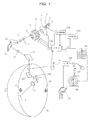
- Figure 1 shows the structure of the perimeter of the invention. In Figure 1,
reference numeral 18 indicates a visual field dome. In the measurement procedure, the eye being examined is aligned with the center of thevisual field dome 18 by means of a base and alignment mechanism (not shown).Background illumination lamps 16 are provided inside thevisual field dome 18. The patient is told to look at atarget 19 projected onto the inside surface ofvisual field dome 18. When the patient visually recognizes thetarget 19, he responds for the examiner by operating aresponse switch 17, or by giving a vocal response, or by any other suitable means. - In Figure 1, an optical projection
system comprising parts 1 to 15 is used to project thetarget 19. The optical system can, for example, be disposed inside the type of projector arm shown in Figures 4 and 5.Reference numeral 2 denotes a target projection lamp, behind which there is a reflectingmirror 1. Light from thelamp 2 passes through acondenser lens 3, atarget plate 4 andturret filters 5 to 7, and falls incident on arelay lens 8. Thetarget plate 4 is used to set the size of the target. For this, thetarget plate 4 is provided with a plurality of apertures, with the desired aperture being moved into the optical axis under the control of aCPU 101. - Of the turret filters 5 to 7,
filter 5 is a color filter that selects the target color, and filters 6 and 7 are two different types of ND filter used to regulate the amount of light. From therelay lens 8, the light passes through a focusinglens 9 and a shutter 10 (aperture), deflected by amirror 11, and the light passes through arelay lens 12 and is reflected by amirror 13. In this embodiment, two mirrors, 14A and 14B, are provided to control the positioning of the projected target. For this, a drive means such as a motor (not shown) is used to rotate each mirror under the control of theCPU 101. Finally, the target is projected from aprojector lens 15 onto the projection surface of thevisual field dome 18. - The perimeter of this embodiment can be used as an automatic perimeter by controlling the target projection mechanism (1 to 15) under the control of the
CPU 101 in accordance with the predetermined program, and visual field measurement can also be performed manually. That is, by applying operating means such as a display, mouse, tablet and the like to the operation system of a manual Goldmann perimeter, the manual operation system was implemented electronically. For this, the control system of the perimeter of the invention was arranged as follows. - The
CPU 101 is connected to adisplay monitor 102 such as a CRT or liquid crystal display, anexternal storage unit 103 that uses floppy disks or MO media or the like, aprinter 104, and so forth. Via an I/O interface 106, the system is also provided with an input device or devices such as amouse 107, asuitable pointing device 109, and a light-pen 108 used with themonitor 102. - The
pointing device 109 can be a slide-pad operated by finger or special stylus, or a digitizer device as shown in Figure 3. The digitizer device of Figure 3 can be used on a digitizer pad on which is printed (or displayed) a conventional Goldmann perimeter recording chart pattern. Apositioning aperture 152 can be used to check the position on the digitizer pad, and aclick button 153 is used for command entry when the target spot position is determined or when the patient's responses are to be recorded. The current position of thepointing device 109 on the digitizer pad is output as coordinate data with the aid of coordinate detection systems such as mechanical, ball-based or optical systems. - Mouse, light-pen and pointing device systems are each used for coordinate entry, and it is not necessary to provide all of these devices. The examiner only needs to be provided with an operating feel that is as close as possible to that provided by using a recording chart with a conventional mechanical Goldmann perimeter.
- Below, an example of a
system using monitor 102 and light-pen 108 is described. - To implement automated perimeter operation, the target projection mechanism (1 to 15) is controlled via an interface and drive means such as motors and solenoids (not shown) under the control of the
CPU 101 according to a predetermined program. This is the same as in the prior art, and further description thereof is therefore omitted. - When used as a (semi-) manual perimeter, the angles of the
mirrors pen 108 orpointing device 109 is used to make an indication on the recording chart pattern displayed on themonitor 102. If themouse 107 or light-pen 108 is used as the input device, it produces coordinate signals on the basis of which a pointer is displayed on themonitor 102 to show the operation position. This enables the device button to be operated for command implementation. In the case of the digitizer device of Figure 3, it is possible to use an arrangement in which themonitor 102 is used for display, and one in which the chart pattern is printed on the digitizer pad or shown on a display laid on the digitizer pad. - The chart pattern displayed on the
monitor 102 is a recording chart pattern such as isoptometry suitable for any kind of perimetry system. Apattern 151 shown in Figure 2 is an example. The pattern corresponds to the target projection surface of thevisual field dome 18. The examiner uses the light-pen 108 or other input device for position entry on the pattern to control the projection position for the target spot and to record the patient's response position. - A suitable control system can be used to switch between inputting the target spot projection position and inputting the patient's response position. For example, a keyboard or foot-switch (not shown) can be used to switch between projection position input mode and response position input mode.
- Based on the control and operating data that are input, the
CPU 101 controls the target projection mechanism (1 to 15) and the target projection positioning. - Figure 6 shows a flow chart of an examination sequence in the case of a perimeter according to the present invention used as a (semi-) manual perimeter. In this example, a touch-panel is provided on the
monitor 102 to input the coordinate data. Themouse 107, light-pen 108 andpointing device 109 are not used, but can be readily replaced by the touch-panel in the following control operation. - With reference to Figure 6, when the power is switched on, the motors are initialized in step S1. These are the motors used to drive the components such as the
mirrors projector lens 15. In step S2, X and Y axes and scales are displayed on themonitor 102. The chart pattern of Figure 2 can be used for this with the positions on the display and the touch-panel input coordinate system being associated beforehand with the actual visual field dome coordinate system. - In step S3, the system waits for input via the touch-panel on the
monitor 102. When touch-panel input is received, the input coordinates are detected and the motors are energized in step S4 to project the target at the position thus input. The projection mechanism (1 to 15) is then controlled in step S5 to project the target spot at the coordinate position input on the touch-panel by the examiner. - Starting from step S6, the system enters a loop in which the target is projected at a plurality of points and the responses by the patient are input. In step S6, the touch-panel input is monitored to determine whether or not the input position has changed. If the input position has changed, the motors are energized in step S7 to project the target at the input position, as is the same with step S4. Thus, the examiner, while examining the patient, provides the patient with prompts, moving the target and requesting the patient to respond by using the
response switch 17. - In step S8, it is determined whether or not there has been a patient input from the
response switch 17. If there has been an input, the process moves to step S11. If there is no input, the process moves to step S9. In step S9, it is determined whether or not input via the touch-panel has stopped (that is, whether the examiner's finger or input stylus is off the touch-panel). If input has stopped, the target display is turned off in step S10 and the process goes back to step S3. - If there is a patient response, the process moves from step S8 to step S11, and the response is plotted on the screen of the
monitor 102. Each such plot point corresponds to the target projection coordinates at the time of response switch operation. In addition to being plotted on-screen, the coordinate data corresponding to the response point are stored in memory for subsequent output processing and the like. In step S12, it is determined whether or not the examination has been finished. This can be done by, for example, determining the state of a Finish switch (not shown). If the examination is not finished, the process reverts to step S3, and the process of projecting and moving the target and recording responses is repeated. - If the examination is finished, an appropriate output process is effected via the
monitor 102 in step S13. For example, a plurality of response positions can be connected on themonitor 102 to display a graph of the visual field range. In this step S13, the response position data can be displayed graphically on themonitor 102 in conformation with the examination system concerned by subjecting the data to computation appropriate for the examination system. In step S14, examination results are printed out by theprinter 104. The output can be in the form of the screen dump in step S13, or can be in the form of a graph or table of target spot control and response positions. Along with this, theexternal storage unit 103 is used to store the examination data in a specified format. - Thus, the examiner just tracks the display on the
monitor 102 using the touch-panel to readily set each of the target positions and obtain the patient's response at each point. Examination results are plotted on-screen and printed out automatically, freeing the examiner of the complex and onerous tasks of recording data on a chart, controlling the target positioning and plotting response positions that are required in the case of a conventional manual Goldmann perimeter. Patient prompts can be done arbitrarily, so that the examiner can use his own expertise and experience to decide the target projection sequence and positioning in accordance with the condition and state of the disease concerned, making it possible to expeditiously complete a full and proper examination. - As can be understood from the foregoing description and explanation, a perimeter according to the present invention can be used to project the target spot at the desired positions more easily than in the case of a conventional manual Goldmann perimeter in which the target spot position is controlled mechanically. In particular, the ability to concentrate the operating system in the touch-panel and monitor 102 and light-pen 108 (or the
mouse 107 orpointing device 109 and the like) input devices makes it easy to operate during the examination procedure. - Operation is further facilitated by displaying the operation status on the
monitor 102. For example, the current target projection position determined using the light-pen 108 (ormouse 107 or pointing device 109) can be displayed on themonitor 102 within the range of visual field that is shown in the form of a concentric recording chart pattern. When theresponse switch 17 is operated to signify a patient response, the position of the target spot at the time of the response can be acquired as a measurement result, and the response position can be displayed in a different color than the target projection position. It is also possible to automatically record the target spot position at the time of the response by the response switch or a spoken response by the patient. - If the light-
pen 108 or the like is used, information relating to visual field measurement can be input in the form of handwritten characters. Handwritten input and character recognition of handwritten character input are known technologies, so further description thereof will be omitted. Also, menus required to control the operating modes of devices involved in visual field measurement can be displayed on the monitor 102 (or a digitizer pad or touch-panel or the like), enabling the examiner to use the light-pen 108 to make selections on the menus. - Instead of performing measurements in accordance with a fixed, preset program, measurement points and procedures can also be readily changed to match the needs of the patient or the condition of the patient's eye. This makes it possible to complete an examination with speed and efficiency, and, as compared to a conventional mechanical Goldmann perimeter, makes the examination less onerous and tiring for the examiner as well as the patient. This is accomplished by applying an electronic system to the operation of the Goldmann perimeter and using the electronic implementation to simulate the operational feel of a conventional manual (mechanical) Goldmann perimeter. This makes the perimeter as easy to use as an automatic perimeter, and enables examinations to be performed with good adaptability and efficiency.
- Furthermore, the target projection mechanism (1 to 15) is not controlled by purely mechanical means; instead, the perimeter can utilize the target projection mechanism of an automatic perimeter, making it possible easily and at a low cost to configure as both an automatic perimeter and as a manual (semi-automatic) perimeter.
- As described in the foregoing, the perimeter according to the present invention that projects a target spot onto the inside surface of a visual field dome and records the position of the projected target spot and patient's responses relating to the visual recognition thereof, comprises an optical projection system for projecting the target spot on the inside surface of the visual field dome; control means for electronically controlling a position at which the target spot is projected; input means used for entry of control information for control of the projection position of the target spot by the control means and for recording of response information relating to the patient's response; and display means for displaying the control information and response information supplied via the input means, said display means being adapted for use as an input surface for entry of the control and response information by the input means. In such an arrangement electronics is used to simulate the feel of a conventional manual (mechanical) Goldmann perimeter, making the perimeter as easy to use as an automatic perimeter, and enabling examinations to be performed with good adaptability and efficiency.
Claims (4)
- A perimeter that projects a target spot (19) onto the inside surface of a visual field dome (18) and records the position of the projected target spot and patient's responses (17) relating to the visual recognition thereof, comprising:an optical projection system ( 1 to 15) for projecting the target spot (19) on the inside surface of the visual field dome (18);control means (101) for electronically controlling a position at which the target spot (19) is projected;input means (107, 108, 109) used for entry of control information for control of the projection position of the target spot by the control means and for recording of response information relating to the patient's response; anddisplay means (102) for displaying the control information and response information supplied via the input means, said display means being adapted for use as an input surface for entry of the control and response information by the input means.
- The perimeter according to claim 1, wherein the input means (107, 108, 109) is a coordinate input device such as a mouse or light-pen.
- The perimeter according to claim 1, wherein the display means (102) is a display device such as a CRT display, a liquid crystal display or a digitizer pad.
- The perimeter according to claim 1, wherein the input surface is provided or printed with a mechanical perimeter recording chart pattern (151), which is used by an examiner to determine positions for entry of the control information and response information.
Applications Claiming Priority (2)
| Application Number | Priority Date | Filing Date | Title |
|---|---|---|---|
| JP2001057577A JP4901009B2 (en) | 2001-03-02 | 2001-03-02 | Perimeter |
| JP2001057577 | 2001-03-02 |
Publications (2)
| Publication Number | Publication Date |
|---|---|
| EP1236432A2 true EP1236432A2 (en) | 2002-09-04 |
| EP1236432A3 EP1236432A3 (en) | 2003-07-02 |
Family
ID=18917425
Family Applications (1)
| Application Number | Title | Priority Date | Filing Date |
|---|---|---|---|
| EP02251385A Ceased EP1236432A3 (en) | 2001-03-02 | 2002-02-27 | Perimeter |
Country Status (3)
| Country | Link |
|---|---|
| US (1) | US6685321B2 (en) |
| EP (1) | EP1236432A3 (en) |
| JP (1) | JP4901009B2 (en) |
Cited By (7)
| Publication number | Priority date | Publication date | Assignee | Title |
|---|---|---|---|---|
| EP1407710A1 (en) * | 2002-10-08 | 2004-04-14 | Inami & Co., Ltd. | Computer controlled perimetry system |
| WO2007090144A2 (en) * | 2006-01-31 | 2007-08-09 | Novavision, Inc. | System and methods for the treatment of retinal diseases |
| US7367671B2 (en) | 2002-02-08 | 2008-05-06 | Novavision, Inc. | Process and device for the training of human vision |
| EP2022391A1 (en) * | 2007-07-31 | 2009-02-11 | Kabushiki Kaisha TOPCON | Ophtalmologic information-processing apparatus and ophthalmologic examination apparatus |
| US7594728B2 (en) | 2005-12-16 | 2009-09-29 | Novavision, Inc. | Adjustable device for vision testing and therapy |
| US7748846B2 (en) | 2006-07-25 | 2010-07-06 | Novavision, Inc. | Dynamic fixation stimuli for visual field testing and therapy |
| US7753524B2 (en) | 2002-02-08 | 2010-07-13 | Novavision, Inc. | Process and device for treating blind regions of the visual field |
Families Citing this family (8)
| Publication number | Priority date | Publication date | Assignee | Title |
|---|---|---|---|---|
| JP2004208705A (en) * | 2002-12-26 | 2004-07-29 | Nidek Co Ltd | Optometric apparatus |
| JP4476050B2 (en) * | 2004-06-30 | 2010-06-09 | 株式会社ニデック | Perimeter |
| JP4724451B2 (en) * | 2005-04-08 | 2011-07-13 | 株式会社トーメーコーポレーション | Ophthalmic equipment |
| JP4806602B2 (en) * | 2006-08-09 | 2011-11-02 | 興和株式会社 | Perimeter |
| JP2009045175A (en) * | 2007-08-17 | 2009-03-05 | Topcon Corp | Ophthalmologic examination system |
| JP5575726B2 (en) * | 2011-11-02 | 2014-08-20 | 興和株式会社 | Perimeter |
| JP6128814B2 (en) * | 2012-11-29 | 2017-05-17 | 株式会社ニデック | Visual function evaluation program and visual function evaluation apparatus |
| DE102015217682A1 (en) | 2015-09-16 | 2017-03-16 | Carl Zeiss Ag | Device for eye examination |
Citations (1)
| Publication number | Priority date | Publication date | Assignee | Title |
|---|---|---|---|---|
| WO1999052419A1 (en) * | 1998-04-10 | 1999-10-21 | Visual Resources, Inc. | Method and apparatus for training visual attention capabilities of a subject |
Family Cites Families (9)
| Publication number | Priority date | Publication date | Assignee | Title |
|---|---|---|---|---|
| GB2054894A (en) * | 1979-07-13 | 1981-02-18 | Woolf B N | Eye testing apparatus |
| US5108170A (en) * | 1989-12-29 | 1992-04-28 | Kabushiki Kaisha Topcon | Perimetric instrument |
| JP2863944B2 (en) * | 1990-03-29 | 1999-03-03 | 株式会社トプコン | Perimeter measurement device |
| JP3032261B2 (en) * | 1990-09-27 | 2000-04-10 | 株式会社トプコン | Automatic perimeter |
| JPH0654804A (en) * | 1992-08-05 | 1994-03-01 | Canon Inc | Perimeter |
| JP3317754B2 (en) * | 1993-09-16 | 2002-08-26 | 株式会社トプコン | Perimeter measurement device |
| US5459536A (en) * | 1993-12-27 | 1995-10-17 | Alcon Laboratories, Inc. | Apparatus and method for automated perimetry |
| JPH08191794A (en) * | 1995-01-19 | 1996-07-30 | Nikon Corp | Optometry system having remote-control device |
| US5589897A (en) * | 1995-05-01 | 1996-12-31 | Stephen H. Sinclair | Method and apparatus for central visual field mapping and optimization of image presentation based upon mapped parameters |
-
2001
- 2001-03-02 JP JP2001057577A patent/JP4901009B2/en not_active Expired - Fee Related
-
2002
- 2002-02-27 EP EP02251385A patent/EP1236432A3/en not_active Ceased
- 2002-03-01 US US10/090,063 patent/US6685321B2/en not_active Expired - Lifetime
Patent Citations (1)
| Publication number | Priority date | Publication date | Assignee | Title |
|---|---|---|---|---|
| WO1999052419A1 (en) * | 1998-04-10 | 1999-10-21 | Visual Resources, Inc. | Method and apparatus for training visual attention capabilities of a subject |
Cited By (12)
| Publication number | Priority date | Publication date | Assignee | Title |
|---|---|---|---|---|
| US7367671B2 (en) | 2002-02-08 | 2008-05-06 | Novavision, Inc. | Process and device for the training of human vision |
| US7682021B2 (en) | 2002-02-08 | 2010-03-23 | Novavision, Inc. | System and methods for the treatment of retinal diseases |
| US7753524B2 (en) | 2002-02-08 | 2010-07-13 | Novavision, Inc. | Process and device for treating blind regions of the visual field |
| EP1407710A1 (en) * | 2002-10-08 | 2004-04-14 | Inami & Co., Ltd. | Computer controlled perimetry system |
| US6783240B2 (en) | 2002-10-08 | 2004-08-31 | Inami & Co., Ltd. | Computer controlled perimetry system |
| US7594728B2 (en) | 2005-12-16 | 2009-09-29 | Novavision, Inc. | Adjustable device for vision testing and therapy |
| WO2007090144A2 (en) * | 2006-01-31 | 2007-08-09 | Novavision, Inc. | System and methods for the treatment of retinal diseases |
| WO2007090144A3 (en) * | 2006-01-31 | 2008-04-10 | Novavision Inc | System and methods for the treatment of retinal diseases |
| US7748846B2 (en) | 2006-07-25 | 2010-07-06 | Novavision, Inc. | Dynamic fixation stimuli for visual field testing and therapy |
| US7753526B2 (en) | 2006-07-25 | 2010-07-13 | Novavision, Inc. | Frequency doubling fixation stimuli for visual field testing and therapy |
| EP2022391A1 (en) * | 2007-07-31 | 2009-02-11 | Kabushiki Kaisha TOPCON | Ophtalmologic information-processing apparatus and ophthalmologic examination apparatus |
| US7641339B2 (en) | 2007-07-31 | 2010-01-05 | Kabushiki Kaisha Topcon | Ophthalmologic information processing apparatus and ophthalmologic examination apparatus |
Also Published As
| Publication number | Publication date |
|---|---|
| JP4901009B2 (en) | 2012-03-21 |
| US20020128558A1 (en) | 2002-09-12 |
| EP1236432A3 (en) | 2003-07-02 |
| US6685321B2 (en) | 2004-02-03 |
| JP2002253502A (en) | 2002-09-10 |
Similar Documents
| Publication | Publication Date | Title |
|---|---|---|
| US6685321B2 (en) | Perimeter | |
| US6175610B1 (en) | Medical technical system controlled by vision-detected operator activity | |
| US7594188B2 (en) | Operating menu for a surgical microscope | |
| US7458685B2 (en) | Automated fundus imaging system | |
| EP2394569B1 (en) | Ophthalmic apparatus | |
| JP4724451B2 (en) | Ophthalmic equipment | |
| JP2002224038A (en) | Fundus camera | |
| US7283299B2 (en) | Magnifying observation apparatus, method for observing magnified image, and computer-readable medium | |
| JP2010233998A (en) | Ophthalmological apparatus | |
| US5196872A (en) | Data acquistion and pupil tracking apparatus for an ophthalmologocial instrument | |
| US9049990B2 (en) | Corneal endothelial cell photographing apparatus | |
| JPH05192299A (en) | Fundus camera | |
| JP4250062B2 (en) | Ophthalmic equipment | |
| JPH105178A (en) | Visual line input device | |
| US5150137A (en) | Positioning system for pupil imaging optics | |
| JPH08252224A (en) | Ophthalmological device | |
| JP4649160B2 (en) | Optometry system | |
| JP2005323712A (en) | Inspection apparatus | |
| KR0129784B1 (en) | Apparatus for fire extinguishing utilizing spray wvisual inspection supporting system for printed circuit board ater | |
| JP2003019117A (en) | Fundus camera | |
| JP2011097998A (en) | Ophthalmic photographing apparatus | |
| JPH11104080A (en) | Ophthalmic device | |
| JPS58821B2 (en) | electronic microscope | |
| EP1407710B1 (en) | Computer controlled perimetry system | |
| JP5896186B2 (en) | Ophthalmic equipment |
Legal Events
| Date | Code | Title | Description |
|---|---|---|---|
| PUAI | Public reference made under article 153(3) epc to a published international application that has entered the european phase |
Free format text: ORIGINAL CODE: 0009012 |
|
| AK | Designated contracting states |
Kind code of ref document: A2 Designated state(s): AT BE CH CY DE DK ES FI FR GB GR IE IT LI LU MC NL PT SE TR |
|
| AX | Request for extension of the european patent |
Free format text: AL;LT;LV;MK;RO;SI |
|
| PUAL | Search report despatched |
Free format text: ORIGINAL CODE: 0009013 |
|
| AK | Designated contracting states |
Designated state(s): AT BE CH CY DE DK ES FI FR GB GR IE IT LI LU MC NL PT SE TR |
|
| AX | Request for extension of the european patent |
Extension state: AL LT LV MK RO SI |
|
| 17P | Request for examination filed |
Effective date: 20031219 |
|
| AKX | Designation fees paid |
Designated state(s): DE ES FR GB IT PT |
|
| 17Q | First examination report despatched |
Effective date: 20040308 |
|
| RBV | Designated contracting states (corrected) |
Designated state(s): AT BE CH CY DE DK ES FR GB IT LI PT |
|
| RBV | Designated contracting states (corrected) |
Designated state(s): DE ES FR GB IT PT |
|
| 17Q | First examination report despatched |
Effective date: 20040308 |
|
| 17Q | First examination report despatched |
Effective date: 20040308 |
|
| STAA | Information on the status of an ep patent application or granted ep patent |
Free format text: STATUS: THE APPLICATION HAS BEEN REFUSED |
|
| 18R | Application refused |
Effective date: 20080530 |