EP1235541B1 - Procede de fabrication d'un dispositif de connexion entre un recipient et un contenant, dispositif de connexion correspondant et ensemble pret a l'emploi comprenant un tel dispositif - Google Patents
Procede de fabrication d'un dispositif de connexion entre un recipient et un contenant, dispositif de connexion correspondant et ensemble pret a l'emploi comprenant un tel dispositif Download PDFInfo
- Publication number
- EP1235541B1 EP1235541B1 EP00988880A EP00988880A EP1235541B1 EP 1235541 B1 EP1235541 B1 EP 1235541B1 EP 00988880 A EP00988880 A EP 00988880A EP 00988880 A EP00988880 A EP 00988880A EP 1235541 B1 EP1235541 B1 EP 1235541B1
- Authority
- EP
- European Patent Office
- Prior art keywords
- base
- cap
- edge
- container
- recipient
- Prior art date
- Legal status (The legal status is an assumption and is not a legal conclusion. Google has not performed a legal analysis and makes no representation as to the accuracy of the status listed.)
- Expired - Lifetime
Links
Images


Classifications
-
- A—HUMAN NECESSITIES
- A61—MEDICAL OR VETERINARY SCIENCE; HYGIENE
- A61J—CONTAINERS SPECIALLY ADAPTED FOR MEDICAL OR PHARMACEUTICAL PURPOSES; DEVICES OR METHODS SPECIALLY ADAPTED FOR BRINGING PHARMACEUTICAL PRODUCTS INTO PARTICULAR PHYSICAL OR ADMINISTERING FORMS; DEVICES FOR ADMINISTERING FOOD OR MEDICINES ORALLY; BABY COMFORTERS; DEVICES FOR RECEIVING SPITTLE
- A61J1/00—Containers specially adapted for medical or pharmaceutical purposes
- A61J1/14—Details; Accessories therefor
- A61J1/20—Arrangements for transferring or mixing fluids, e.g. from vial to syringe
- A61J1/2089—Containers or vials which are to be joined to each other in order to mix their contents
-
- B—PERFORMING OPERATIONS; TRANSPORTING
- B65—CONVEYING; PACKING; STORING; HANDLING THIN OR FILAMENTARY MATERIAL
- B65D—CONTAINERS FOR STORAGE OR TRANSPORT OF ARTICLES OR MATERIALS, e.g. BAGS, BARRELS, BOTTLES, BOXES, CANS, CARTONS, CRATES, DRUMS, JARS, TANKS, HOPPERS, FORWARDING CONTAINERS; ACCESSORIES, CLOSURES, OR FITTINGS THEREFOR; PACKAGING ELEMENTS; PACKAGES
- B65D51/00—Closures not otherwise provided for
- B65D51/002—Closures to be pierced by an extracting-device for the contents and fixed on the container by separate retaining means
-
- B—PERFORMING OPERATIONS; TRANSPORTING
- B65—CONVEYING; PACKING; STORING; HANDLING THIN OR FILAMENTARY MATERIAL
- B65D—CONTAINERS FOR STORAGE OR TRANSPORT OF ARTICLES OR MATERIALS, e.g. BAGS, BARRELS, BOTTLES, BOXES, CANS, CARTONS, CRATES, DRUMS, JARS, TANKS, HOPPERS, FORWARDING CONTAINERS; ACCESSORIES, CLOSURES, OR FITTINGS THEREFOR; PACKAGING ELEMENTS; PACKAGES
- B65D81/00—Containers, packaging elements, or packages, for contents presenting particular transport or storage problems, or adapted to be used for non-packaging purposes after removal of contents
- B65D81/32—Containers, packaging elements, or packages, for contents presenting particular transport or storage problems, or adapted to be used for non-packaging purposes after removal of contents for packaging two or more different materials which must be maintained separate prior to use in admixture
- B65D81/3205—Separate rigid or semi-rigid containers joined to each other at their external surfaces
- B65D81/3211—Separate rigid or semi-rigid containers joined to each other at their external surfaces coaxially and provided with means facilitating admixture
-
- A—HUMAN NECESSITIES
- A61—MEDICAL OR VETERINARY SCIENCE; HYGIENE
- A61J—CONTAINERS SPECIALLY ADAPTED FOR MEDICAL OR PHARMACEUTICAL PURPOSES; DEVICES OR METHODS SPECIALLY ADAPTED FOR BRINGING PHARMACEUTICAL PRODUCTS INTO PARTICULAR PHYSICAL OR ADMINISTERING FORMS; DEVICES FOR ADMINISTERING FOOD OR MEDICINES ORALLY; BABY COMFORTERS; DEVICES FOR RECEIVING SPITTLE
- A61J1/00—Containers specially adapted for medical or pharmaceutical purposes
- A61J1/14—Details; Accessories therefor
- A61J1/1406—Septums, pierceable membranes
-
- A—HUMAN NECESSITIES
- A61—MEDICAL OR VETERINARY SCIENCE; HYGIENE
- A61J—CONTAINERS SPECIALLY ADAPTED FOR MEDICAL OR PHARMACEUTICAL PURPOSES; DEVICES OR METHODS SPECIALLY ADAPTED FOR BRINGING PHARMACEUTICAL PRODUCTS INTO PARTICULAR PHYSICAL OR ADMINISTERING FORMS; DEVICES FOR ADMINISTERING FOOD OR MEDICINES ORALLY; BABY COMFORTERS; DEVICES FOR RECEIVING SPITTLE
- A61J1/00—Containers specially adapted for medical or pharmaceutical purposes
- A61J1/14—Details; Accessories therefor
- A61J1/1468—Containers characterised by specific material properties
-
- A—HUMAN NECESSITIES
- A61—MEDICAL OR VETERINARY SCIENCE; HYGIENE
- A61J—CONTAINERS SPECIALLY ADAPTED FOR MEDICAL OR PHARMACEUTICAL PURPOSES; DEVICES OR METHODS SPECIALLY ADAPTED FOR BRINGING PHARMACEUTICAL PRODUCTS INTO PARTICULAR PHYSICAL OR ADMINISTERING FORMS; DEVICES FOR ADMINISTERING FOOD OR MEDICINES ORALLY; BABY COMFORTERS; DEVICES FOR RECEIVING SPITTLE
- A61J1/00—Containers specially adapted for medical or pharmaceutical purposes
- A61J1/14—Details; Accessories therefor
- A61J1/20—Arrangements for transferring or mixing fluids, e.g. from vial to syringe
- A61J1/2003—Accessories used in combination with means for transfer or mixing of fluids, e.g. for activating fluid flow, separating fluids, filtering fluid or venting
- A61J1/2006—Piercing means
- A61J1/201—Piercing means having one piercing end
-
- A—HUMAN NECESSITIES
- A61—MEDICAL OR VETERINARY SCIENCE; HYGIENE
- A61J—CONTAINERS SPECIALLY ADAPTED FOR MEDICAL OR PHARMACEUTICAL PURPOSES; DEVICES OR METHODS SPECIALLY ADAPTED FOR BRINGING PHARMACEUTICAL PRODUCTS INTO PARTICULAR PHYSICAL OR ADMINISTERING FORMS; DEVICES FOR ADMINISTERING FOOD OR MEDICINES ORALLY; BABY COMFORTERS; DEVICES FOR RECEIVING SPITTLE
- A61J1/00—Containers specially adapted for medical or pharmaceutical purposes
- A61J1/14—Details; Accessories therefor
- A61J1/20—Arrangements for transferring or mixing fluids, e.g. from vial to syringe
- A61J1/2003—Accessories used in combination with means for transfer or mixing of fluids, e.g. for activating fluid flow, separating fluids, filtering fluid or venting
- A61J1/2006—Piercing means
- A61J1/2013—Piercing means having two piercing ends
-
- A—HUMAN NECESSITIES
- A61—MEDICAL OR VETERINARY SCIENCE; HYGIENE
- A61M—DEVICES FOR INTRODUCING MEDIA INTO, OR ONTO, THE BODY; DEVICES FOR TRANSDUCING BODY MEDIA OR FOR TAKING MEDIA FROM THE BODY; DEVICES FOR PRODUCING OR ENDING SLEEP OR STUPOR
- A61M2207/00—Methods of manufacture, assembly or production
Definitions
- the present invention relates to a manufacturing process a connection device between a container and a container, a corresponding connection device and a ready to use assembly comprising such a device.
- a component of a pharmaceutical preparation such as that its active ingredient
- a stopper made of a relatively soft material, such as a elastomer. Liquid may be introduced into this container, after puncturing the cap, which allows the dissolution or suspension of the component contained in the container, so as to obtain a preparation in the form liquid, including medication or vaccine, ready to be administered to a patient.
- a device of connection between the aforementioned closed container and a container contains liquid capable of being introduced in the container, once opened by perforation from its cap.
- a connection device comprises a base adapted to be immobilized on the container, in the interior volume of which an internal bore is formed.
- This device also includes a mounted piston sliding in the aforementioned bore, which is provided with a member puncturing the container cap, such as a needle dig.
- This piston is movable between a storage position, in which the perforating member is not in contact with the cap, and a transfer position, in which the perforating member passes through this plug.
- This connection device also includes a cap having a cover from which walls extend lateral defining an opening.
- This headdress is suitable for cover the outer periphery of the base, in particular during storage of the ready-to-use assembly, formed by the container and its connection device.
- EP-A-0 728 457 provides for provide the inner wall of the cap with at least one edge device projecting radially inwards.
- it is planned to cover the outer wall in look of the base by means of a sealing material of high viscosity.
- a sealing material of high viscosity During the sliding movement between the base and the cap, the edges of the latter scrape the material seal arranged on the cap and induce formation a circumferential seal, which is allowed thanks to the high viscosity of the material used.
- the circumferential joint thus formed does not provide a perfect seal, whatever either the relative pressure conditions between the exterior and the interior of the base.
- the circumferential joint aforementioned is likely to be removed from the area of edges, so that this joint is no longer able to perform its sealing function satisfactorily.
- the invention proposes to implement a process for manufacturing a connection device which guarantees a seal on the one hand satisfactory between the walls opposite the base and the cap and on the other hand an easy disassembly of these two elements.
- the invention makes it possible to achieve the objectives previously mentioned.
- each edge of the hard element by means of a lubricating agent leads to the wetting of these edges and, given the characteristics of the lubrication used, to form a lubrication film which is immobilized on these edges.
- first and second elements are between 10 and 15.
- each edge seal penetrates the wall opposite the element the less hard at a depth of about 10 to 15 micrometers.
- a sealant the characteristics of which of hanging are such that it leaves a film of integral lubrication of or each element that it covers, allows an operator to easily remove, the base cap, immediately before use.
- This film advantageously has a thickness of between 5 and 10 micrometers.
- the presence of this film also confers secondary sealing component, insofar as this film occupies the surface micro-defects of the edge element that it covers.
- this film cannot be chased in function of pressure differences between the exterior and the interior of the base, which is advantageous compared to to the prior art.
- the lubrication agent advantageously has a viscosity, at 20 ° C, between 150 and 1500 centistokes.
- the lubricant used is advantageously a high spreading power, thanks to its low surface tension and its low viscosity. This him allows satisfactory filling of micro-porosities edges of the harder element penetrating into the element more soft.
- the lubrication agent is advantageously immiscible with water. This hydrophobic character confers a power high sealing to the lubrication film.
- the lubricant is preferably stable and chemically neutral, and little subject to evaporation. He owns for example an evaporation factor of around 0.5%, determined by a sample of 2 grams of lubrication agent placed in a 50 ml container and subjected to a temperature of 150 ° C for 24 hours. This lubrication agent has advantageously a higher surface tension than that air.
- This lubricating agent can be a silicone oil or a fluorinated oil.
- one covers the first element provided with at least one edge per spraying the lubrication agent.
- the invention finally relates to an assembly ready for use comprising a closed container containing a product, in particular a pharmaceutical preparation, and a device for connection as defined above, mounted on said container.
- FIG. 1 represents a container 2, for example a glass vial, containing a product not shown, which is for example a powder intended to form an oral vaccine. It can also be any other type of preparation pharmaceuticals, in particular all types of drugs.
- the container 2 is closed by means of a plug 4, made of known manner in a relatively soft material, such as a elastomer.
- Figure 1 also illustrates a device, designated as a whole by reference 6, allowing connection between the container 2 and a container not shown. This last can be a syringe containing a liquid intended to dissolve or suspend the product contained in container 2, or even a flexible pocket, or another glass bottle.
- This connection device 6 comprises a base 8 capable to be secured, in known manner, on the container 2 by its lower end 10.
- the latter is extended by a main portion 12 cylindrical, defining a bore inside 14 and an outer peripheral wall 16, noticeably smooth.
- the base 8 is made of a material relatively soft, such as low density polyethylene.
- connection device 6 also includes a piston 18 able to slide in the bore 14 of the base 8.
- This piston is provided, in known manner, with a perforation needle 20 of the plug 4.
- the piston 18 is movable between a position storage, in which the needle is not in contact with the cap, and a transfer position, in which the needle 20 pierces the plug 4 and is in contact liquid in container 2.
- connection device of the invention comprises also a cap, generally designated by the reference 22, which has a cover 24 from which extend from the side walls 26, of cross section circular. These define an open end 28 of the cap, intended for the fitting of the base 8.
- Cap 22 is made of a material harder than the base 8, for example high density polyethylene.
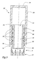
- FIG. 2 illustrates a processing phase belonging to the manufacturing process, the connection device 6 according to the invention.
- a spraying device 32 tubular in shape.
- the latter has several orifices radials 34, ensuring the spraying of a lubricating agent with which the spraying device is supplied 32.
- This lubricating agent is for example an oil fluorinated, such as that marketed by the company WYNN'S FRANCE under the reference WYNNOX H4, whose viscosity is 180 centistokes at 20 ° C.
- Figure 3 shows a phase of setting up the connection device 6 of the invention.
- the piston 18 not shown on this Figure 3, in the bore 14 of the base 8.
- the cap 22 on the outer periphery of the base 8.
- the assembly thus constituted is then secured to container 2, so to be stored.
- the edges 30 penetrate the wall 16 opposite the base 8, which provides a satisfactory seal and prevents migration external microbial towards the internal volume of the base 8, and therefore of the needle 20.
- the presence of the film 36 provides a secondary sealing component.
- the cap 22 is removed from the base 8, by a substantially vertical action directed upwards. This action is particularly easy, due to the presence of film 36 ensuring lubrication between the facing walls of the cap 22 and the base 8. We then proceed so conventional, to the perforation of the cap 4 of the container 2 at by means of needle 20. Finally, in the vicinity of the base 8, the container to which the container 2 must be logged.
- the invention is not limited to the examples described and represented. Indeed, it can be planned to carry out a any number of edges, similar to those of the cap 22. Furthermore, it is possible to make the base 8 in a harder material than that constituting the cap 22. In the latter case, the outer periphery of the base 8 has protruding edges, similar to those 30 radially outward and cooperating with the wall smooth interior of the cap, the aforementioned smooth wall having an inner diameter which is smaller than the outer diameter of the edges of the base.
Description
- une embase destinée à être immobilisée sur ce récipient,
- un piston mobile dans un alésage de ladite embase, ce piston étant pourvu d'un organe de perforation apte à traverser un bouchon du récipient, et
- une coiffe recouvrant au moins partiellement la périphérie extérieure de l'embase,
- une embase destinée à être immobilisée sur ce récipient,
- un piston mobile dans un alésage de l'embase, ce piston étant pourvu d'un organe de perforation apte à traverser un bouchon du récipient, et
- une coiffe recouvrant au moins partiellement la périphérie extérieure de l'embase,
- la ou chaque arête du premier élément pénètre dans la paroi en regard du second élément, selon une profondeur comprise entre 10 et 15 micromètres ;
- le film de lubrification possède une épaisseur comprise entre 5 et 10 micromètres ; et
- la différence de duretés entre les premier et second éléments, sur l'échelle Shore D, est comprise entre 10 et 15.
- la figure 1 est une vue en coupe longitudinale, illustrant les différents éléments constitutifs d'un dispositif de connexion conforme à l'invention ;
- la figure 2 est une vue en coupe longitudinale, illustrant une opération de pulvérisation d'un agent de lubrification appartenant au procédé de traitement de l'invention ; et
- la figure 3 est une vue en coupe longitudinale, illustrant une embase et une coiffe du dispositif de la figure 1, réalisées conformément à l'invention.
Claims (11)
- Procédé de fabrication d'un dispositif de connexion (6) entre un récipient fermé (2) et un contenant, ce dispositif de connexion (6) comprenant :caractérisé en ce qu'on réalise un premier élément (22) de l'ensemble formé par l'embase (8) et la coiffe (22) en un matériau plus dur que le second élément (8) dudit ensemble (8, 22), en ce qu'on munit le premier élément (22) d'au moins une arête périphérique (30) destinée à pénétrer, de façon étanche, dans une région en regard du second élément (8), et en ce qu'on recouvre la ou chaque arête (30) du premier élément (8) au moyen d'un agent de lubrification adapté pour former, une fois cette opération de recouvrement effectuée, un film de lubrification (36) apte à rester en place sur la ou chaque arête d'étanchéité, lors du déplacement relatif de la coiffe (22) et de l'embase (8), ainsi que lorsque cette coiffe (22) et cette embase (8) sont immobiles l'une par rapport à l'autre.une embase (8) destinée à être immobilisée sur ce récipient (2),un piston (18) mobile dans un alésage (14) de ladite embase (8), ce piston (18) étant pourvu d'un organe de perforation (20) apte à traverser un bouchon (4) du récipient (2), etune coiffe (22) recouvrant au moins partiellement la périphérie extérieure (16) de l'embase (8),
- Procédé selon la revendication 1, caractérisé en ce que l'agent de lubrification possède une viscosité à 20°C, comprise entre 150 et 1 500 centistokes.
- Procédé selon l'une des revendications 1 ou 2, caractérisé en ce que l'agent de lubrification n'est pas miscible avec l'eau.
- Procédé selon l'une des revendications 1 à 3, caractérisé en ce que l'agent de lubrification est une huile siliconée.
- Procédé selon l'une des revendications 1 à 3, caractérisé en ce que l'agent de lubrification est une huile fluorée.
- Procédé selon l'une des revendications 1 à 5, caractérisé en ce qu'on recouvre le premier élément (22) muni d'au moins une arête (30), par pulvérisation de l'agent de lubrification.
- Dispositif de connexion (6) entre un récipient fermé (2) et un contenant, ce dispositif de connexion (6) comprenant :caractérisé en ce qu'un premier élément (22) de l'ensemble formé par l'embase (8) et la coiffe (22) est réalisée en un matériau plus dur que le second élément (8) dudit ensemble (8, 22), en ce que ledit premier élément (22) est muni d'au moins une arête périphérique (30) pénétrant, de façon étanche, dans une région en regard du second élément (8) et en ce que la ou chaque arête (30) du premier élément (22) est recouverte au moyen d'un film de lubrification (36) apte à rester en place sur la ou chaque arête (30), lors du déplacement relatif de la coiffe (22) et de l'embase (8), ainsi que lorsque cette coiffe (22) et cette embase (8) sont immobiles l'une par rapport à l'autre.une embase (8) destinée à être immobilisée sur ce récipient (2),un piston (18) mobile dans un alésage (14) de l'embase (8), ce piston (18) étant pourvu d'un organe de perforation (20) apte à traverser un bouchon (4) du récipient (2), etune coiffe (22) recouvrant au moins partiellement la périphérie extérieure (16) de l'embase (8),
- Dispositif selon la revendication 7, caractérisé en ce que la ou chaque arête (30) du premier élément (22) pénètre dans la paroi en regard du second élément (8), selon une profondeur comprise entre 10 et 15 micromètres.
- Dispositif selon l'une des revendications 7 ou 8, caractérisé en ce que le film de lubrification (36) possède une épaisseur comprise entre 5 et 10 micromètres.
- Dispositif selon l'une des revendications 7 à 9, caractérisé en ce que la différence de duretés entre les premier (22) et second (8) éléments, sur l'échelle Shore D, est comprise entre 10 et 15.
- Ensemble prêt à l'emploi comprenant un récipient fermé (2) contenant un produit, notamment une préparation pharmaceutique, et un dispositif de connexion (6) selon l'une quelconque des revendications 7 à 10, monté sur ledit récipient (2).
Applications Claiming Priority (3)
| Application Number | Priority Date | Filing Date | Title |
|---|---|---|---|
| FR9915634 | 1999-12-10 | ||
| FR9915634A FR2802183B1 (fr) | 1999-12-10 | 1999-12-10 | Procede de fabrication d'un dispositif de connexion entre un recipient et un contenant, dispositif de connexion correspondant et ensemble pret a l'emploi comprenant un tel dispositif |
| PCT/FR2000/003413 WO2001041699A1 (fr) | 1999-12-10 | 2000-12-06 | Procede de fabrication d'un dispositif de connexion entre un recipient et un contenant, dispositif de connexion correspondant et ensemble pret a l'emploi comprenant un tel dispositif |
Publications (2)
| Publication Number | Publication Date |
|---|---|
| EP1235541A1 EP1235541A1 (fr) | 2002-09-04 |
| EP1235541B1 true EP1235541B1 (fr) | 2003-07-23 |
Family
ID=9553138
Family Applications (1)
| Application Number | Title | Priority Date | Filing Date |
|---|---|---|---|
| EP00988880A Expired - Lifetime EP1235541B1 (fr) | 1999-12-10 | 2000-12-06 | Procede de fabrication d'un dispositif de connexion entre un recipient et un contenant, dispositif de connexion correspondant et ensemble pret a l'emploi comprenant un tel dispositif |
Country Status (21)
| Country | Link |
|---|---|
| US (1) | US7632260B2 (fr) |
| EP (1) | EP1235541B1 (fr) |
| JP (1) | JP4628632B2 (fr) |
| KR (1) | KR100825564B1 (fr) |
| CN (1) | CN1209090C (fr) |
| AT (1) | ATE245404T1 (fr) |
| AU (1) | AU767619B2 (fr) |
| BR (1) | BR0015388A (fr) |
| CA (1) | CA2386861C (fr) |
| DE (1) | DE60004092T2 (fr) |
| DK (1) | DK1235541T3 (fr) |
| ES (1) | ES2202211T3 (fr) |
| FR (1) | FR2802183B1 (fr) |
| HK (1) | HK1048246B (fr) |
| HU (1) | HUP0203893A2 (fr) |
| MX (1) | MXPA02005776A (fr) |
| PL (1) | PL196543B1 (fr) |
| PT (1) | PT1235541E (fr) |
| RU (1) | RU2236834C2 (fr) |
| WO (1) | WO2001041699A1 (fr) |
| ZA (1) | ZA200202626B (fr) |
Families Citing this family (11)
| Publication number | Priority date | Publication date | Assignee | Title |
|---|---|---|---|---|
| JP2007512102A (ja) | 2003-11-20 | 2007-05-17 | ザ ヘンリー エム. ジャクソン ファウンデーション フォー ザ アドヴァンスメント オブ ミリタリー メディシン, インク. | 流体の吸引のための携帯可能な手動ポンプ |
| US8337475B2 (en) | 2004-10-12 | 2012-12-25 | C. R. Bard, Inc. | Corporeal drainage system |
| TW200640522A (en) * | 2005-02-09 | 2006-12-01 | Kaken Pharma Co Ltd | Syringe device and method of preparing medicine using the device |
| WO2007038643A1 (fr) | 2005-09-26 | 2007-04-05 | C.R. Bard, Inc. | Systèmes de raccord de cathéther |
| RU2011143298A (ru) * | 2009-03-27 | 2013-05-10 | Клоужер Системз Интернэшнл, Инк. | Формованная крышка с улучшенным распределением смазки |
| USD655017S1 (en) | 2010-06-17 | 2012-02-28 | Yukon Medical, Llc | Shroud |
| FR2967655B1 (fr) * | 2010-11-24 | 2014-03-14 | Biocorp Rech Et Dev | Dispositif de bouchage d'un recipient, recipient equipe d'un tel dispositif et procede de fermeture d'un lot de tels recipients |
| USD681230S1 (en) | 2011-09-08 | 2013-04-30 | Yukon Medical, Llc | Shroud |
| KR101395087B1 (ko) | 2013-04-12 | 2014-05-16 | 한국엔테랄푸드(주) | 경장영양을 위한 경관급식용 유동식 공급장치 |
| GB201415869D0 (en) * | 2014-09-08 | 2014-10-22 | Eulysis Uk Ltd | Container And Closure |
| US10702281B2 (en) | 2016-07-18 | 2020-07-07 | Merit Medical Systems, Inc. | Inflatable radial artery compression device |
Family Cites Families (61)
| Publication number | Priority date | Publication date | Assignee | Title |
|---|---|---|---|---|
| US2847996A (en) * | 1953-08-13 | 1958-08-19 | Miljam Instr Corp | Hypodermic syringe |
| FR1423549A (fr) | 1965-02-05 | 1966-01-03 | Emballage de seringue | |
| FR2227020B1 (fr) * | 1973-04-27 | 1975-08-22 | Radiologie Cie Gle | |
| US3976073A (en) * | 1974-05-01 | 1976-08-24 | Baxter Laboratories, Inc. | Vial and syringe connector assembly |
| US4195632A (en) * | 1978-05-03 | 1980-04-01 | Cutter Laboratories, Inc. | Fluid flow valve |
| JPS5580586A (en) * | 1978-12-08 | 1980-06-17 | Kazuhiko Kodama | Production of *kasuri* like woven yarn |
| US4296786A (en) * | 1979-09-28 | 1981-10-27 | The West Company | Transfer device for use in mixing a primary solution and a secondary or additive substance |
| US4507113A (en) * | 1982-11-22 | 1985-03-26 | Derata Corporation | Hypodermic jet injector |
| DE3324406C1 (de) * | 1983-07-06 | 1984-11-22 | Gustav 8922 Peiting Stifter | Fluiddichte gelenkige Verbindung zwischen Hohlprofilen |
| US4589879A (en) * | 1983-11-04 | 1986-05-20 | Baxter Travenol Laboratories, Inc. | Cannula assembly having closed, pressure-removable piercing tip |
| IT1173370B (it) * | 1984-02-24 | 1987-06-24 | Erba Farmitalia | Dispositivo di sicurezza per collegare una siringa alla imboccatura di un flacone contenente un farmaco o di un tubicino per l'erogazione del farmaco della siringa |
| US4552277A (en) * | 1984-06-04 | 1985-11-12 | Richardson Robert D | Protective shield device for use with medicine vial and the like |
| US4607671A (en) * | 1984-08-21 | 1986-08-26 | Baxter Travenol Laboratories, Inc. | Reconstitution device |
| US4759756A (en) * | 1984-09-14 | 1988-07-26 | Baxter Travenol Laboratories, Inc. | Reconstitution device |
| US4675020A (en) * | 1985-10-09 | 1987-06-23 | Kendall Mcgaw Laboratories, Inc. | Connector |
| US4662878A (en) * | 1985-11-13 | 1987-05-05 | Patents Unlimited Ltd. | Medicine vial adaptor for needleless injector |
| US4639250A (en) * | 1986-02-20 | 1987-01-27 | Becton, Dickinson And Company | Syringe barrel and hypodermic needle assembly |
| US4713060A (en) * | 1986-06-20 | 1987-12-15 | Becton, Dickinson And Company | Syringe assembly |
| JPS643188A (en) * | 1987-06-25 | 1989-01-06 | Shin Etsu Chem Co Ltd | Damavaricin fc carbamate derivative |
| US4898209A (en) | 1988-09-27 | 1990-02-06 | Baxter International Inc. | Sliding reconstitution device with seal |
| US4989209A (en) * | 1989-03-24 | 1991-01-29 | Motorola, Inc. | Method and apparatus for testing high pin count integrated circuits |
| US5152965A (en) * | 1989-06-02 | 1992-10-06 | Abbott Laboratories | Two-piece reagent container assembly |
| US5060704A (en) | 1990-05-25 | 1991-10-29 | David Bull Laboratories Pty. Ltd. | Suction transfer assembly |
| US5169388A (en) * | 1990-06-07 | 1992-12-08 | Gensia Pharmaceuticals, Inc. | Pressure-activated medication dispenser |
| US5232029A (en) * | 1990-12-06 | 1993-08-03 | Abbott Laboratories | Additive device for vial |
| US5186323A (en) * | 1991-06-24 | 1993-02-16 | Pfleger Frederick W | Dual compartment mixing container |
| DE4122476A1 (de) | 1991-07-06 | 1993-01-07 | Leopold Pharma Gmbh | Verfahren und vorrichtung zum ueberleiten von zwei oder mehr sterilen fluessigkeiten im geschlossenen system |
| JP3065735B2 (ja) * | 1991-08-29 | 2000-07-17 | 株式会社ニッショー | 薬剤容器およびそれを用いた薬液注入装置 |
| US5308347A (en) * | 1991-09-18 | 1994-05-03 | Fujisawa Pharmaceutical Co., Ltd. | Transfusion device |
| US5352191A (en) | 1991-10-25 | 1994-10-04 | Fujisawa Pharmaceutical Co., Ltd. | Transfusion device |
| US5247972A (en) * | 1991-12-17 | 1993-09-28 | Whittier Medical, Inc. | Alignment guide for hypodermic syringe |
| US5224515A (en) * | 1992-01-30 | 1993-07-06 | Porex Technologies Corp. | Tube closure |
| US5423791A (en) * | 1992-03-31 | 1995-06-13 | Bartlett; J. Mark | Valve device for medical fluid transfer |
| CA2093560C (fr) * | 1992-04-10 | 2005-06-07 | Minoru Honda | Contenant pour fluide |
| JP2605345Y2 (ja) * | 1992-05-01 | 2000-07-10 | 株式会社大塚製薬工場 | 薬剤容器 |
| JPH05317383A (ja) * | 1992-05-19 | 1993-12-03 | Nissho Corp | 薬剤容器との連通手段を備えた溶解液容器 |
| US5279576A (en) * | 1992-05-26 | 1994-01-18 | George Loo | Medication vial adapter |
| US5279583A (en) * | 1992-08-28 | 1994-01-18 | Shober Jr Robert C | Retractable injection needle assembly |
| US5344417A (en) * | 1992-09-11 | 1994-09-06 | Becton, Dickinson And Company | Universal fitting for inoculation receptacles |
| US5364386A (en) * | 1993-05-05 | 1994-11-15 | Hikari Seiyaku Kabushiki Kaisha | Infusion unit |
| EP0660690B1 (fr) * | 1993-06-30 | 1999-08-25 | Baxter International Inc. | Adaptateur pour flacons |
| US5429614A (en) * | 1993-06-30 | 1995-07-04 | Baxter International Inc. | Drug delivery system |
| US5397303A (en) * | 1993-08-06 | 1995-03-14 | River Medical, Inc. | Liquid delivery device having a vial attachment or adapter incorporated therein |
| CA2164318C (fr) | 1993-12-28 | 1999-12-07 | Tetsuro Higashikawa | Seringue |
| US5429256A (en) * | 1994-01-24 | 1995-07-04 | Kestenbaum; Alan D. | Drug withdrawal system for container |
| DE4414697C2 (de) * | 1994-04-27 | 1998-06-18 | Caremed Vertriebsgesellschaft | Vorrichtung zum Transferieren und Entnehmen von Flüssigkeiten aus Flaschen, Beuteln oder ähnlichen Behältnissen für medizinische Zwecke |
| KR100441231B1 (ko) | 1994-06-24 | 2004-10-12 | 아이시유메디칼인코오포레이티드 | 유체반송장치및사용방법 |
| US5526853A (en) * | 1994-08-17 | 1996-06-18 | Mcgaw, Inc. | Pressure-activated medication transfer system |
| US5613291A (en) * | 1995-01-25 | 1997-03-25 | Becton, Dickinson And Company | Method for providing a sterility seal in a medicinal storage bottle |
| FR2738550B1 (fr) * | 1995-09-11 | 1997-11-07 | Biodome | Dispositif d'obturation d'un recipient lui-meme ferme, ensemble pour dispenser un produit comprenant un tel recipient et un tel dispositif d'obturation |
| DE29516650U1 (de) | 1995-10-21 | 1995-12-14 | Clinico Formtechnik Gmbh | Einmalspritze zur Erzeugung variabler Medikamentenkonzentration durch Lösung oder Verdünnung. |
| CA2211629A1 (fr) * | 1996-09-17 | 1998-03-17 | Bernard Sams | Ensemble-raccord pour fiole a medicaments |
| FR2753624B1 (fr) | 1996-09-25 | 1999-04-16 | Biodome | Dispositif de connexion, en particulier entre un recipient avec bouchon perforable et une seringue |
| GB9701413D0 (en) * | 1997-01-24 | 1997-03-12 | Smithkline Beecham Biolog | Novel device |
| US6090092A (en) * | 1997-12-04 | 2000-07-18 | Baxter International Inc. | Sliding reconstitution device with seal |
| JP3223151B2 (ja) * | 1997-12-08 | 2001-10-29 | 株式会社エムケイテック | 蓋付き密閉容器 |
| US6382442B1 (en) * | 1998-04-20 | 2002-05-07 | Becton Dickinson And Company | Plastic closure for vials and other medical containers |
| US6681946B1 (en) * | 1998-02-26 | 2004-01-27 | Becton, Dickinson And Company | Resealable medical transfer set |
| US6191382B1 (en) | 1998-04-02 | 2001-02-20 | Avery Dennison Corporation | Dynamic laser cutting apparatus |
| US6209738B1 (en) * | 1998-04-20 | 2001-04-03 | Becton, Dickinson And Company | Transfer set for vials and medical containers |
| US6022339A (en) * | 1998-09-15 | 2000-02-08 | Baxter International Inc. | Sliding reconstitution device for a diluent container |
-
1999
- 1999-12-10 FR FR9915634A patent/FR2802183B1/fr not_active Expired - Fee Related
-
2000
- 2000-12-06 RU RU2002118615A patent/RU2236834C2/ru not_active IP Right Cessation
- 2000-12-06 WO PCT/FR2000/003413 patent/WO2001041699A1/fr active IP Right Grant
- 2000-12-06 JP JP2001542869A patent/JP4628632B2/ja not_active Expired - Lifetime
- 2000-12-06 CA CA 2386861 patent/CA2386861C/fr not_active Expired - Lifetime
- 2000-12-06 HU HU0203893A patent/HUP0203893A2/hu unknown
- 2000-12-06 CN CNB008144834A patent/CN1209090C/zh not_active Expired - Fee Related
- 2000-12-06 US US10/129,208 patent/US7632260B2/en not_active Expired - Lifetime
- 2000-12-06 AU AU25231/01A patent/AU767619B2/en not_active Expired
- 2000-12-06 PT PT00988880T patent/PT1235541E/pt unknown
- 2000-12-06 ES ES00988880T patent/ES2202211T3/es not_active Expired - Lifetime
- 2000-12-06 DK DK00988880T patent/DK1235541T3/da active
- 2000-12-06 PL PL356131A patent/PL196543B1/pl unknown
- 2000-12-06 AT AT00988880T patent/ATE245404T1/de not_active IP Right Cessation
- 2000-12-06 MX MXPA02005776A patent/MXPA02005776A/es active IP Right Grant
- 2000-12-06 BR BR0015388A patent/BR0015388A/pt not_active IP Right Cessation
- 2000-12-06 EP EP00988880A patent/EP1235541B1/fr not_active Expired - Lifetime
- 2000-12-06 DE DE2000604092 patent/DE60004092T2/de not_active Expired - Lifetime
- 2000-12-06 KR KR1020027007349A patent/KR100825564B1/ko not_active IP Right Cessation
-
2002
- 2002-04-04 ZA ZA200202626A patent/ZA200202626B/en unknown
-
2003
- 2003-01-08 HK HK03100209.4A patent/HK1048246B/zh not_active IP Right Cessation
Also Published As
| Publication number | Publication date |
|---|---|
| FR2802183A1 (fr) | 2001-06-15 |
| BR0015388A (pt) | 2002-07-02 |
| CN1209090C (zh) | 2005-07-06 |
| EP1235541A1 (fr) | 2002-09-04 |
| AU767619B2 (en) | 2003-11-20 |
| FR2802183B1 (fr) | 2002-02-22 |
| PT1235541E (pt) | 2003-11-28 |
| DK1235541T3 (da) | 2003-10-27 |
| RU2236834C2 (ru) | 2004-09-27 |
| CA2386861C (fr) | 2009-10-27 |
| JP4628632B2 (ja) | 2011-02-09 |
| US20020183714A1 (en) | 2002-12-05 |
| PL356131A1 (en) | 2004-06-14 |
| PL196543B1 (pl) | 2008-01-31 |
| HK1048246A1 (en) | 2003-03-28 |
| KR100825564B1 (ko) | 2008-04-25 |
| ZA200202626B (en) | 2003-04-30 |
| HUP0203893A2 (en) | 2003-03-28 |
| WO2001041699A1 (fr) | 2001-06-14 |
| RU2002118615A (ru) | 2004-03-20 |
| AU2523101A (en) | 2001-06-18 |
| JP2003516187A (ja) | 2003-05-13 |
| HK1048246B (zh) | 2006-01-06 |
| ATE245404T1 (de) | 2003-08-15 |
| CN1379653A (zh) | 2002-11-13 |
| DE60004092T2 (de) | 2004-04-22 |
| CA2386861A1 (fr) | 2001-06-14 |
| US7632260B2 (en) | 2009-12-15 |
| DE60004092D1 (de) | 2003-08-28 |
| MXPA02005776A (es) | 2003-10-14 |
| ES2202211T3 (es) | 2004-04-01 |
| KR20020065557A (ko) | 2002-08-13 |
Similar Documents
| Publication | Publication Date | Title |
|---|---|---|
| EP1226077B1 (fr) | Dispositif de connexion pret a l'emploi | |
| EP1235541B1 (fr) | Procede de fabrication d'un dispositif de connexion entre un recipient et un contenant, dispositif de connexion correspondant et ensemble pret a l'emploi comprenant un tel dispositif | |
| EP2717827B1 (fr) | Dispositif de connexion entre un récipient et un contenant, procédé d'assemblage et d'utilisation d'un tel dispositif | |
| EP1115361B1 (fr) | Dispositif de connexion entre un recipient et un contenant et ensemble pret a l'emploi comprenant un tel dispositif | |
| EP1150639B1 (fr) | Dispositif de connexion entre un recipient et un contenant et ensemble pret a l'emploi comprenant un tel dispositif | |
| EP0705645A1 (fr) | Pompe à fluide sans volume mort | |
| WO2003070147A2 (fr) | Dispositif de connexion entre un recipient et un contenant et ensemble pret a l'emploi comprenant un tel dispositif | |
| FR2539302A1 (fr) | Seringue a usage medical | |
| FR2858931A1 (fr) | Dispositif d'administration orale d'un medicament | |
| CA2393378A1 (fr) | Dispositif de connexion entre un recipient et un contenant et ensemble pret a l'emploi comprenant un tel dispositif | |
| FR2900344A1 (fr) | Dispositif d'injection avec aiguille retractable | |
| FR2726768A1 (fr) | Dispositif de seringue fixable sur un flacon | |
| EP2705866B1 (fr) | Dispositif pour réduire la douleur liée à l'introduction dans la peau d'une aiguille d'une seringue | |
| CH621067A5 (fr) | ||
| EP2308452B1 (fr) | Aiguille perforante | |
| FR2821827A1 (fr) | Dispositif de connexion entre un recipient et un contenant et ensemble pret a l'emploi comprenant un tel dispositif | |
| EP2822870B1 (fr) | Dispositif de bouchage et recipient equipe d'un tel dispositif | |
| CH570169A5 (en) | Rear filling liq syringe distributor - with filling device | |
| EP0299991B1 (fr) | Dispositif de connexion pour un appareil de transfert d'un liquide | |
| FR2644349A1 (fr) | Seringue a utilisation unique | |
| EP3352821B1 (fr) | Ensemble de distribution comportant une seringue et un dispositif de protection pour aiguille | |
| EP3383342B1 (fr) | Dispositif de connexion entre un récipient et un contenant et ensemble de connexion comprenant un tel dispositif | |
| CA1315626C (fr) | Dispositif de connexion pour adapter un organe d'extremite sur un appareil de transfert d'un liquide | |
| CH706928B1 (fr) | Dispositif pour réduire la douleur liée à l'introduction dans la peau d'une aiguille d'une seringue. |
Legal Events
| Date | Code | Title | Description |
|---|---|---|---|
| PUAI | Public reference made under article 153(3) epc to a published international application that has entered the european phase |
Free format text: ORIGINAL CODE: 0009012 |
|
| 17P | Request for examination filed |
Effective date: 20020404 |
|
| AK | Designated contracting states |
Kind code of ref document: A1 Designated state(s): AT BE CH CY DE DK ES FI FR GB GR IE IT LI LU MC NL PT SE TR |
|
| AX | Request for extension of the european patent |
Free format text: AL;LT;LV;MK;RO;SI |
|
| GRAH | Despatch of communication of intention to grant a patent |
Free format text: ORIGINAL CODE: EPIDOS IGRA |
|
| GRAH | Despatch of communication of intention to grant a patent |
Free format text: ORIGINAL CODE: EPIDOS IGRA |
|
| GRAA | (expected) grant |
Free format text: ORIGINAL CODE: 0009210 |
|
| AK | Designated contracting states |
Designated state(s): AT BE CH CY DE DK ES FI FR GB GR IE IT LI LU MC NL PT SE TR |
|
| REG | Reference to a national code |
Ref country code: GB Ref legal event code: FG4D Free format text: NOT ENGLISH |
|
| REG | Reference to a national code |
Ref country code: CH Ref legal event code: EP |
|
| REG | Reference to a national code |
Ref country code: IE Ref legal event code: FG4D Free format text: FRENCH |
|
| REF | Corresponds to: |
Ref document number: 60004092 Country of ref document: DE Date of ref document: 20030828 Kind code of ref document: P |
|
| GBT | Gb: translation of ep patent filed (gb section 77(6)(a)/1977) | ||
| REG | Reference to a national code |
Ref country code: SE Ref legal event code: TRGR |
|
| PGFP | Annual fee paid to national office [announced via postgrant information from national office to epo] |
Ref country code: CY Payment date: 20031111 Year of fee payment: 4 |
|
| PGFP | Annual fee paid to national office [announced via postgrant information from national office to epo] |
Ref country code: FI Payment date: 20031116 Year of fee payment: 4 |
|
| PGFP | Annual fee paid to national office [announced via postgrant information from national office to epo] |
Ref country code: LU Payment date: 20031117 Year of fee payment: 4 |
|
| REG | Reference to a national code |
Ref country code: GR Ref legal event code: EP Ref document number: 20030404177 Country of ref document: GR |
|
| PGFP | Annual fee paid to national office [announced via postgrant information from national office to epo] |
Ref country code: MC Payment date: 20031118 Year of fee payment: 4 |
|
| PGFP | Annual fee paid to national office [announced via postgrant information from national office to epo] |
Ref country code: DK Payment date: 20031119 Year of fee payment: 4 |
|
| PGFP | Annual fee paid to national office [announced via postgrant information from national office to epo] |
Ref country code: GR Payment date: 20031127 Year of fee payment: 4 |
|
| PGFP | Annual fee paid to national office [announced via postgrant information from national office to epo] |
Ref country code: PT Payment date: 20031222 Year of fee payment: 4 |
|
| LTIE | Lt: invalidation of european patent or patent extension |
Effective date: 20030723 |
|
| REG | Reference to a national code |
Ref country code: ES Ref legal event code: FG2A Ref document number: 2202211 Country of ref document: ES Kind code of ref document: T3 |
|
| PLBE | No opposition filed within time limit |
Free format text: ORIGINAL CODE: 0009261 |
|
| STAA | Information on the status of an ep patent application or granted ep patent |
Free format text: STATUS: NO OPPOSITION FILED WITHIN TIME LIMIT |
|
| 26N | No opposition filed |
Effective date: 20040426 |
|
| PG25 | Lapsed in a contracting state [announced via postgrant information from national office to epo] |
Ref country code: FI Free format text: LAPSE BECAUSE OF NON-PAYMENT OF DUE FEES Effective date: 20041204 |
|
| PG25 | Lapsed in a contracting state [announced via postgrant information from national office to epo] |
Ref country code: CY Free format text: LAPSE BECAUSE OF NON-PAYMENT OF DUE FEES Effective date: 20041206 Ref country code: LU Free format text: LAPSE BECAUSE OF NON-PAYMENT OF DUE FEES Effective date: 20041206 |
|
| PG25 | Lapsed in a contracting state [announced via postgrant information from national office to epo] |
Ref country code: MC Free format text: LAPSE BECAUSE OF NON-PAYMENT OF DUE FEES Effective date: 20041231 |
|
| PG25 | Lapsed in a contracting state [announced via postgrant information from national office to epo] |
Ref country code: DK Free format text: LAPSE BECAUSE OF NON-PAYMENT OF DUE FEES Effective date: 20050103 |
|
| PG25 | Lapsed in a contracting state [announced via postgrant information from national office to epo] |
Ref country code: PT Free format text: LAPSE BECAUSE OF NON-PAYMENT OF DUE FEES Effective date: 20050606 |
|
| PG25 | Lapsed in a contracting state [announced via postgrant information from national office to epo] |
Ref country code: GR Free format text: LAPSE BECAUSE OF NON-PAYMENT OF DUE FEES Effective date: 20050704 |
|
| REG | Reference to a national code |
Ref country code: DK Ref legal event code: EBP |
|
| REG | Reference to a national code |
Ref country code: PT Ref legal event code: MM4A Effective date: 20050606 |
|
| PGFP | Annual fee paid to national office [announced via postgrant information from national office to epo] |
Ref country code: AT Payment date: 20091119 Year of fee payment: 10 |
|
| PGFP | Annual fee paid to national office [announced via postgrant information from national office to epo] |
Ref country code: NL Payment date: 20091224 Year of fee payment: 10 |
|
| REG | Reference to a national code |
Ref country code: NL Ref legal event code: V1 Effective date: 20110701 |
|
| PG25 | Lapsed in a contracting state [announced via postgrant information from national office to epo] |
Ref country code: AT Free format text: LAPSE BECAUSE OF NON-PAYMENT OF DUE FEES Effective date: 20101206 |
|
| PG25 | Lapsed in a contracting state [announced via postgrant information from national office to epo] |
Ref country code: NL Free format text: LAPSE BECAUSE OF NON-PAYMENT OF DUE FEES Effective date: 20110701 |
|
| PGFP | Annual fee paid to national office [announced via postgrant information from national office to epo] |
Ref country code: IT Payment date: 20121219 Year of fee payment: 13 |
|
| PGFP | Annual fee paid to national office [announced via postgrant information from national office to epo] |
Ref country code: BE Payment date: 20121227 Year of fee payment: 13 |
|
| BERE | Be: lapsed |
Owner name: *BIODOME Effective date: 20131231 |
|
| PG25 | Lapsed in a contracting state [announced via postgrant information from national office to epo] |
Ref country code: BE Free format text: LAPSE BECAUSE OF NON-PAYMENT OF DUE FEES Effective date: 20131231 |
|
| PGFP | Annual fee paid to national office [announced via postgrant information from national office to epo] |
Ref country code: IE Payment date: 20141229 Year of fee payment: 15 Ref country code: ES Payment date: 20141226 Year of fee payment: 15 |
|
| PGFP | Annual fee paid to national office [announced via postgrant information from national office to epo] |
Ref country code: SE Payment date: 20150102 Year of fee payment: 15 |
|
| PG25 | Lapsed in a contracting state [announced via postgrant information from national office to epo] |
Ref country code: IT Free format text: LAPSE BECAUSE OF NON-PAYMENT OF DUE FEES Effective date: 20131231 |
|
| REG | Reference to a national code |
Ref country code: FR Ref legal event code: PLFP Year of fee payment: 16 |
|
| PG25 | Lapsed in a contracting state [announced via postgrant information from national office to epo] |
Ref country code: IT Free format text: LAPSE BECAUSE OF NON-PAYMENT OF DUE FEES Effective date: 20131206 |
|
| REG | Reference to a national code |
Ref country code: SE Ref legal event code: EUG |
|
| PG25 | Lapsed in a contracting state [announced via postgrant information from national office to epo] |
Ref country code: SE Free format text: LAPSE BECAUSE OF NON-PAYMENT OF DUE FEES Effective date: 20151207 |
|
| REG | Reference to a national code |
Ref country code: IE Ref legal event code: MM4A |
|
| PG25 | Lapsed in a contracting state [announced via postgrant information from national office to epo] |
Ref country code: IE Free format text: LAPSE BECAUSE OF NON-PAYMENT OF DUE FEES Effective date: 20151206 |
|
| REG | Reference to a national code |
Ref country code: FR Ref legal event code: PLFP Year of fee payment: 17 |
|
| REG | Reference to a national code |
Ref country code: ES Ref legal event code: FD2A Effective date: 20170127 |
|
| PG25 | Lapsed in a contracting state [announced via postgrant information from national office to epo] |
Ref country code: ES Free format text: LAPSE BECAUSE OF NON-PAYMENT OF DUE FEES Effective date: 20151207 |
|
| REG | Reference to a national code |
Ref country code: FR Ref legal event code: PLFP Year of fee payment: 18 |
|
| PGFP | Annual fee paid to national office [announced via postgrant information from national office to epo] |
Ref country code: DE Payment date: 20191112 Year of fee payment: 20 |
|
| PGFP | Annual fee paid to national office [announced via postgrant information from national office to epo] |
Ref country code: FR Payment date: 20191106 Year of fee payment: 20 |
|
| PGFP | Annual fee paid to national office [announced via postgrant information from national office to epo] |
Ref country code: CH Payment date: 20191113 Year of fee payment: 20 Ref country code: TR Payment date: 20191202 Year of fee payment: 20 |
|
| PGFP | Annual fee paid to national office [announced via postgrant information from national office to epo] |
Ref country code: GB Payment date: 20191105 Year of fee payment: 20 |
|
| REG | Reference to a national code |
Ref country code: DE Ref legal event code: R071 Ref document number: 60004092 Country of ref document: DE |
|
| REG | Reference to a national code |
Ref country code: CH Ref legal event code: PL |
|
| REG | Reference to a national code |
Ref country code: GB Ref legal event code: PE20 Expiry date: 20201205 |
|
| PG25 | Lapsed in a contracting state [announced via postgrant information from national office to epo] |
Ref country code: GB Free format text: LAPSE BECAUSE OF EXPIRATION OF PROTECTION Effective date: 20201205 |
|
| PG25 | Lapsed in a contracting state [announced via postgrant information from national office to epo] |
Ref country code: TR Free format text: LAPSE BECAUSE OF NON-PAYMENT OF DUE FEES Effective date: 20201206 |