EP1231110A2 - Picture synthesizing apparatus - Google Patents
Picture synthesizing apparatus Download PDFInfo
- Publication number
- EP1231110A2 EP1231110A2 EP02002896A EP02002896A EP1231110A2 EP 1231110 A2 EP1231110 A2 EP 1231110A2 EP 02002896 A EP02002896 A EP 02002896A EP 02002896 A EP02002896 A EP 02002896A EP 1231110 A2 EP1231110 A2 EP 1231110A2
- Authority
- EP
- European Patent Office
- Prior art keywords
- image
- car
- locus
- line
- synthesizing apparatus
- Prior art date
- Legal status (The legal status is an assumption and is not a legal conclusion. Google has not performed a legal analysis and makes no representation as to the accuracy of the status listed.)
- Granted
Links
- 230000002194 synthesizing effect Effects 0.000 title claims abstract description 172
- 239000007787 solid Substances 0.000 claims abstract description 42
- 238000010586 diagram Methods 0.000 claims description 40
- 230000015572 biosynthetic process Effects 0.000 claims description 30
- 238000003786 synthesis reaction Methods 0.000 claims description 30
- 238000001514 detection method Methods 0.000 claims description 24
- 238000006243 chemical reaction Methods 0.000 claims description 12
- 238000012790 confirmation Methods 0.000 claims description 12
- 230000007274 generation of a signal involved in cell-cell signaling Effects 0.000 claims description 2
- 230000001131 transforming effect Effects 0.000 claims description 2
- 230000006870 function Effects 0.000 description 16
- 238000005401 electroluminescence Methods 0.000 description 4
- 241001236644 Lavinia Species 0.000 description 3
- 239000004973 liquid crystal related substance Substances 0.000 description 3
- 230000004044 response Effects 0.000 description 3
- PCTMTFRHKVHKIS-BMFZQQSSSA-N (1s,3r,4e,6e,8e,10e,12e,14e,16e,18s,19r,20r,21s,25r,27r,30r,31r,33s,35r,37s,38r)-3-[(2r,3s,4s,5s,6r)-4-amino-3,5-dihydroxy-6-methyloxan-2-yl]oxy-19,25,27,30,31,33,35,37-octahydroxy-18,20,21-trimethyl-23-oxo-22,39-dioxabicyclo[33.3.1]nonatriaconta-4,6,8,10 Chemical compound C1C=C2C[C@@H](OS(O)(=O)=O)CC[C@]2(C)[C@@H]2[C@@H]1[C@@H]1CC[C@H]([C@H](C)CCCC(C)C)[C@@]1(C)CC2.O[C@H]1[C@@H](N)[C@H](O)[C@@H](C)O[C@H]1O[C@H]1/C=C/C=C/C=C/C=C/C=C/C=C/C=C/[C@H](C)[C@@H](O)[C@@H](C)[C@H](C)OC(=O)C[C@H](O)C[C@H](O)CC[C@@H](O)[C@H](O)C[C@H](O)C[C@](O)(C[C@H](O)[C@H]2C(O)=O)O[C@H]2C1 PCTMTFRHKVHKIS-BMFZQQSSSA-N 0.000 description 2
- 230000002159 abnormal effect Effects 0.000 description 2
- 230000004397 blinking Effects 0.000 description 1
- 239000012141 concentrate Substances 0.000 description 1
- 230000000694 effects Effects 0.000 description 1
- 230000003287 optical effect Effects 0.000 description 1
Images


Classifications
-
- H—ELECTRICITY
- H04—ELECTRIC COMMUNICATION TECHNIQUE
- H04N—PICTORIAL COMMUNICATION, e.g. TELEVISION
- H04N5/00—Details of television systems
- H04N5/222—Studio circuitry; Studio devices; Studio equipment
- H04N5/262—Studio circuits, e.g. for mixing, switching-over, change of character of image, other special effects ; Cameras specially adapted for the electronic generation of special effects
-
- H—ELECTRICITY
- H04—ELECTRIC COMMUNICATION TECHNIQUE
- H04N—PICTORIAL COMMUNICATION, e.g. TELEVISION
- H04N7/00—Television systems
- H04N7/18—Closed-circuit television [CCTV] systems, i.e. systems in which the video signal is not broadcast
- H04N7/181—Closed-circuit television [CCTV] systems, i.e. systems in which the video signal is not broadcast for receiving images from a plurality of remote sources
-
- B—PERFORMING OPERATIONS; TRANSPORTING
- B60—VEHICLES IN GENERAL
- B60R—VEHICLES, VEHICLE FITTINGS, OR VEHICLE PARTS, NOT OTHERWISE PROVIDED FOR
- B60R1/00—Optical viewing arrangements; Real-time viewing arrangements for drivers or passengers using optical image capturing systems, e.g. cameras or video systems specially adapted for use in or on vehicles
- B60R1/20—Real-time viewing arrangements for drivers or passengers using optical image capturing systems, e.g. cameras or video systems specially adapted for use in or on vehicles
- B60R1/22—Real-time viewing arrangements for drivers or passengers using optical image capturing systems, e.g. cameras or video systems specially adapted for use in or on vehicles for viewing an area outside the vehicle, e.g. the exterior of the vehicle
- B60R1/23—Real-time viewing arrangements for drivers or passengers using optical image capturing systems, e.g. cameras or video systems specially adapted for use in or on vehicles for viewing an area outside the vehicle, e.g. the exterior of the vehicle with a predetermined field of view
- B60R1/27—Real-time viewing arrangements for drivers or passengers using optical image capturing systems, e.g. cameras or video systems specially adapted for use in or on vehicles for viewing an area outside the vehicle, e.g. the exterior of the vehicle with a predetermined field of view providing all-round vision, e.g. using omnidirectional cameras
-
- B—PERFORMING OPERATIONS; TRANSPORTING
- B60—VEHICLES IN GENERAL
- B60R—VEHICLES, VEHICLE FITTINGS, OR VEHICLE PARTS, NOT OTHERWISE PROVIDED FOR
- B60R21/00—Arrangements or fittings on vehicles for protecting or preventing injuries to occupants or pedestrians in case of accidents or other traffic risks
-
- B—PERFORMING OPERATIONS; TRANSPORTING
- B62—LAND VEHICLES FOR TRAVELLING OTHERWISE THAN ON RAILS
- B62D—MOTOR VEHICLES; TRAILERS
- B62D15/00—Steering not otherwise provided for
- B62D15/02—Steering position indicators ; Steering position determination; Steering aids
- B62D15/029—Steering assistants using warnings or proposing actions to the driver without influencing the steering system
- B62D15/0295—Steering assistants using warnings or proposing actions to the driver without influencing the steering system by overlaying a vehicle path based on present steering angle over an image without processing that image
-
- B—PERFORMING OPERATIONS; TRANSPORTING
- B60—VEHICLES IN GENERAL
- B60R—VEHICLES, VEHICLE FITTINGS, OR VEHICLE PARTS, NOT OTHERWISE PROVIDED FOR
- B60R2300/00—Details of viewing arrangements using cameras and displays, specially adapted for use in a vehicle
- B60R2300/30—Details of viewing arrangements using cameras and displays, specially adapted for use in a vehicle characterised by the type of image processing
- B60R2300/301—Details of viewing arrangements using cameras and displays, specially adapted for use in a vehicle characterised by the type of image processing combining image information with other obstacle sensor information, e.g. using RADAR/LIDAR/SONAR sensors for estimating risk of collision
-
- B—PERFORMING OPERATIONS; TRANSPORTING
- B60—VEHICLES IN GENERAL
- B60R—VEHICLES, VEHICLE FITTINGS, OR VEHICLE PARTS, NOT OTHERWISE PROVIDED FOR
- B60R2300/00—Details of viewing arrangements using cameras and displays, specially adapted for use in a vehicle
- B60R2300/30—Details of viewing arrangements using cameras and displays, specially adapted for use in a vehicle characterised by the type of image processing
- B60R2300/302—Details of viewing arrangements using cameras and displays, specially adapted for use in a vehicle characterised by the type of image processing combining image information with GPS information or vehicle data, e.g. vehicle speed, gyro, steering angle data
-
- B—PERFORMING OPERATIONS; TRANSPORTING
- B60—VEHICLES IN GENERAL
- B60R—VEHICLES, VEHICLE FITTINGS, OR VEHICLE PARTS, NOT OTHERWISE PROVIDED FOR
- B60R2300/00—Details of viewing arrangements using cameras and displays, specially adapted for use in a vehicle
- B60R2300/30—Details of viewing arrangements using cameras and displays, specially adapted for use in a vehicle characterised by the type of image processing
- B60R2300/304—Details of viewing arrangements using cameras and displays, specially adapted for use in a vehicle characterised by the type of image processing using merged images, e.g. merging camera image with stored images
- B60R2300/305—Details of viewing arrangements using cameras and displays, specially adapted for use in a vehicle characterised by the type of image processing using merged images, e.g. merging camera image with stored images merging camera image with lines or icons
-
- B—PERFORMING OPERATIONS; TRANSPORTING
- B60—VEHICLES IN GENERAL
- B60R—VEHICLES, VEHICLE FITTINGS, OR VEHICLE PARTS, NOT OTHERWISE PROVIDED FOR
- B60R2300/00—Details of viewing arrangements using cameras and displays, specially adapted for use in a vehicle
- B60R2300/60—Details of viewing arrangements using cameras and displays, specially adapted for use in a vehicle characterised by monitoring and displaying vehicle exterior scenes from a transformed perspective
- B60R2300/602—Details of viewing arrangements using cameras and displays, specially adapted for use in a vehicle characterised by monitoring and displaying vehicle exterior scenes from a transformed perspective with an adjustable viewpoint
-
- B—PERFORMING OPERATIONS; TRANSPORTING
- B60—VEHICLES IN GENERAL
- B60R—VEHICLES, VEHICLE FITTINGS, OR VEHICLE PARTS, NOT OTHERWISE PROVIDED FOR
- B60R2300/00—Details of viewing arrangements using cameras and displays, specially adapted for use in a vehicle
- B60R2300/80—Details of viewing arrangements using cameras and displays, specially adapted for use in a vehicle characterised by the intended use of the viewing arrangement
- B60R2300/806—Details of viewing arrangements using cameras and displays, specially adapted for use in a vehicle characterised by the intended use of the viewing arrangement for aiding parking
-
- B—PERFORMING OPERATIONS; TRANSPORTING
- B60—VEHICLES IN GENERAL
- B60R—VEHICLES, VEHICLE FITTINGS, OR VEHICLE PARTS, NOT OTHERWISE PROVIDED FOR
- B60R2300/00—Details of viewing arrangements using cameras and displays, specially adapted for use in a vehicle
- B60R2300/80—Details of viewing arrangements using cameras and displays, specially adapted for use in a vehicle characterised by the intended use of the viewing arrangement
- B60R2300/8093—Details of viewing arrangements using cameras and displays, specially adapted for use in a vehicle characterised by the intended use of the viewing arrangement for obstacle warning
Landscapes
- Engineering & Computer Science (AREA)
- Multimedia (AREA)
- Mechanical Engineering (AREA)
- Signal Processing (AREA)
- Transportation (AREA)
- Chemical & Material Sciences (AREA)
- Combustion & Propulsion (AREA)
- Image Processing (AREA)
- Closed-Circuit Television Systems (AREA)
- Fittings On The Vehicle Exterior For Carrying Loads, And Devices For Holding Or Mounting Articles (AREA)
- Processing Or Creating Images (AREA)
- Image Analysis (AREA)
- Magnetic Resonance Imaging Apparatus (AREA)
- Vehicle Body Suspensions (AREA)
Abstract
Description
- The present invention relates to a picture synthesizing apparatus, particularly to a picture synthesizing apparatus preferable for use in an apparatus which changes a viewpoint, converts images obtained by a plurality of image pickup devices disposed in a car to images from a virtual viewpoint, synthesizes the images, provides an image around the car to a driver, and helps the driver to drive the car, for example, at a parking time.
- As a conventional image display apparatus, an apparatus has been known which changes a viewpoint of an image actually photographed by a camera, converts the image as if the image were photographed from a virtual viewpoint, and displays the image in a monitor as disclosed in "the Principle of virtual Viewpoint Image Synthesis using a Road Surface Model" (the 7th ITS International Conference). Moreover, an apparatus described in Japanese Patent No. 2610146 has been known which superimposes a predicted backward locus corresponding to a steering angle detected by a vehicular steering angle sensor upon an image of a camera mounted in the car.
- However, in the conventional image display apparatus, the predicted backward locus is superimposed upon the image converted as if the image were photographed with the virtual viewpoint, and the image is displayed in the monitor. In this case, there is a problem that a distance to a surrounding solid object is wrongly recognized to be longer than an actual distance in the image of the monitor.
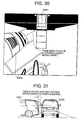
- This respect will be described with reference to the drawing. In FIG. 30, a distance between an illustrated
own car 2401 and anothercar 2402 seems to be still sufficiently long in a monitor image. In actual, however, as shown in FIG. 31, thecar 2401 is considerably close to theother car 2402. This is because the viewpoint is changed to the virtual viewpoint, and thereby objects apart from the ground such as a bumper are projected into a position farther from a camera than an actual position in the converted image. - The present invention has been developed to solve the conventional problem, and an object of the present invention is to provide a picture synthesizing apparatus for superimposing an auxiliary image upon an image converted as if the image were photographed with a virtual viewpoint, and displaying the image in a monitor in order to provide an image such that an approach to a surrounding solid object can easily be predicted from the monitor image.
- According to the present invention, there is provided a picture synthesizing apparatus including: image pickup means mounted in a car; viewpoint change image synthesizing means for changing a viewpoint of an image obtained by the image pickup means and synthesizing the image; car locus line generation means for generating at least one of a locus line of an arbitrary height of the car and a vertical line; and car locus line drawing means for drawing the locus line generated by the car locus line generation means on the image synthesized by the viewpoint change image synthesizing means. By this constitution, the locus line of the arbitrary height of the car is generated, and displayed on the synthesized image obtained by changing a viewpoint, so that a solid locus of the car can be drawn on the synthesized image. Therefore, when the locus of the car is distorted similarly as distortion of a surrounding solid object occurring during viewpoint change and image synthesis, a three-dimensional position relation between surroundings and a predicted locus of the car can easily be grasped, visibility is improved, and it becomes easy to judge contact between the car and the surrounding solid object.
- Moreover, according to the present invention, there is provided a picture synthesizing apparatus including: image pickup means disposed in a car; viewpoint change image synthesizing means for changing a viewpoint of an image obtained by the image pickup means and synthesizing the image; auxiliary line generation means for generating an auxiliary line of an arbitrary position from the car; and auxiliary line drawing means for drawing the auxiliary line generated by the auxiliary line generation means on the image synthesized by the viewpoint change image synthesizing means. By this constitution, the auxiliary line of the arbitrary position from the car is generated, and displayed on the synthesized image obtained by changing a viewpoint. The auxiliary line as a measure of a distance is drawn on the synthesized image, and a driver can easily grasp the distance from another car approaching from behind during driving.
- Furthermore, according to the present invention, there is provided a picture synthesizing apparatus including: image pickup means disposed in a car; viewpoint change image synthesizing means for changing a viewpoint of an image obtained by the image pickup means and synthesizing the image; storage means for storing predetermined data beforehand; and drawing means for superimposing predetermined auxiliary data on the image synthesized by the viewpoint change image synthesizing means based on the data read from the storage means. The image pickup means is disposed so that a rear edge of the car is positioned within a field of view, and the viewpoint change image synthesizing means changes the viewpoint and synthesizes the image including an image of the car. By the constitution, a conversion/synthesis result of the image of the rear edge of the car can be provided to the driver, and it can be easy to judge contact between the car and a solid object around the car.
- According to the present invention, there is provided an image display apparatus comprising: display means for displaying an image synthesized by the picture synthesizing apparatus; and display data conversion control means for converting the image to be displayed into data suitable for the display means.
- By this constitution, the image obtained by the image pickup means or the synthesized image can be displayed in the display means, so that an operator can easily grasp a position relation between a surrounding situation and the car.
- Moreover, according to the present invention, there is provided an image acquirement warning apparatus comprising: detection means for detecting an approaching state of a connection object connected to a car; and warning means for generating arbitrary warning information to an operator based on at least one information of detected information of the detection means and image information synthesized by the picture synthesizing apparatus. The warning information is issued in accordance with the approaching state of the arbitrarily set connection object.
- By this constitution, when the connection object is connected to a rear part of a car body, and the connection object is approaching, the warning information is issued in response to the approaching state, and an operator's attention can be called. Moreover, it is also possible to confirm a completed state at a time of completion of connection.
- Furthermore, according to the present invention, there is provided a car position recognition apparatus comprising: image detection means for detecting an image of an arbitrary object from an image obtained by rear image pickup means which is disposed behind a car to constitute one of image pickup means of the picture synthesizing apparatus, or an image synthesized by the picture synthesizing apparatus; recognition means for recognizing a position relation between the image detected by the image detection means and the image of the car; and comparison judgment means for comparison and judgment with an arbitrary set condition.
- By the constitution, the image obtained by the image pickup means or the synthesized image can be displayed in the display means, and provided to the operator, so that the operator can easily grasp the position of the object (including an object display), or the position relation between the object and the car from the surrounding situation, particularly from the image of the arbitrarily set object.
-
- FIG. 1 is a block diagram showing a constitution of a picture synthesizing apparatus according to a first embodiment of the present invention;
- FIG. 2 is an explanatory view of a synthesized image and locus line obtained by the picture synthesizing apparatus of FIG. 1 and viewed vertically downwards;
- FIG. 3 is a block diagram showing a constitution of locus line calculation means 103B having an arbitrary height in FIG. 1;
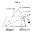
- FIG. 4 is an explanatory view of a flow of processing of the locus line calculation means 103B having the arbitrary height in FIG. 1;
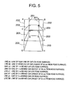
- FIG. 5 is an explanatory view of details of the locus line of FIG. 2.
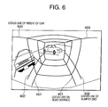
- FIG. 6 is an explanatory view of a rear panorama synthesized image and the locus line obtained by the picture synthesizing apparatus of FIG. 1;
- FIG. 7 is a block diagram showing the constitution of the picture synthesizing apparatus according to a second embodiment of the present invention;
- FIG. 8 is a block diagram showing the constitution of calculation means 502B of the locus line having the arbitrary height in FIG. 7;
- FIG. 9 is an explanatory view of the synthesized image and locus line obtained by the picture synthesizing apparatus of FIG. 7 and viewed backwards;
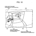
- FIG. 10 is an explanatory view of the synthesized image and locus line obtained by the picture synthesizing apparatus of FIG. 7 and viewed vertically downwards;
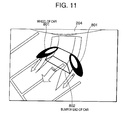
- FIG. 11 is an explanatory view of a solid display of the synthesized image, locus line, and car moving with an elapse of time, obtained by the picture synthesizing apparatus of FIG. 7 and viewed vertically downwards;
- FIG. 12 is a block diagram showing the constitution of the picture synthesizing apparatus according to a third embodiment of the present invention;
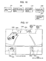
- FIG. 13 is an explanatory view of an emphasized display of the rear panorama synthesized image, locus line, and collision place obtained by the picture synthesizing apparatus of FIG. 12;
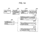
- FIG. 14 is a block diagram showing the constitution of the picture synthesizing apparatus according to a fourth embodiment of the present invention;
- FIG. 15 is an explanatory view of a multi-screen display image and locus line obtained by the picture synthesizing apparatus of FIG. 14;
- FIG. 16 is a block diagram showing the constitution of the picture synthesizing apparatus according to a fifth embodiment of the present invention;
- FIG. 17 is an explanatory view of a multi-screen display image and auxiliary line obtained by the picture synthesizing apparatus of FIG. 16;
- FIG. 18 is a block diagram showing the constitution of an image synthesis/display apparatus according to a sixth embodiment of the present invention;
- FIG. 19 is a layout of an image pickup unit of the image synthesis/display apparatus according to the sixth embodiment of the present invention;
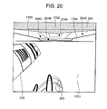
- FIG. 20 is a screen constitution diagram of the image synthesis/display apparatus according to the sixth embodiment of the present invention;
- FIG. 21 is a screen constitution diagram of the image synthesis/display apparatus according to a seventh embodiment of the present invention;
- FIG. 22 is a screen constitution diagram of the image synthesis/display apparatus according to an eighth embodiment of the present invention;
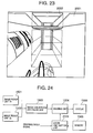
- FIG. 23 is a screen constitution diagram of the image synthesis/display apparatus according to a ninth embodiment of the present invention;
- FIG. 24 is a block diagram showing the constitution of the image synthesis/display apparatus according to a tenth embodiment of the present invention;
- FIG. 25 is a screen constitution diagram of the image synthesis/display apparatus according to an eleventh embodiment of the present invention;
- FIG. 26 is a screen constitution diagram of the image synthesis/display apparatus according to a twelfth embodiment of the present invention;
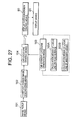
- FIG. 27 is a block diagram showing the constitution of the image synthesis/display apparatus according to a thirteenth embodiment of the present invention;
- FIG. 28 is a block diagram of an image acquirement/warning apparatus according to a fourteenth embodiment of the present invention;
- FIG. 29 is a block diagram of a car position recognition apparatus according to a fifteenth embodiment of the present invention;
- FIG. 30 is a screen constitution diagram of a conventional rear view field display apparatus; and
- FIG. 31 is a position relation diagram of a car showing a problem of the conventional rear view field display apparatus.
-
- Embodiments of the present invention will be described hereinafter in detail with reference to the drawings.
- FIG. 1 is a block diagram showing a constitution of a picture synthesizing apparatus according to a first embodiment. The picture synthesizing apparatus is constituted of image pickup means 101 disposed in a car, viewpoint change image synthesizing means 102, car straight locus line generation means 103, and car locus line drawing means 104.
- The image pickup means 101 is constituted of one or more cameras disposed in a rear or side part of the car, and turns to the rear of the car. The viewpoint change image synthesizing means 102 inputs one or more images obtained by the image pickup means 101, and outputs a synthesized image viewed from a virtual viewpoint. The car straight locus line generation means 103 inputs a size and shape of the car, camera parameter for changing the viewpoint, and image pickup situation of the image pickup means 101, and outputs a locus line in a case in which the car runs straight backwards. The car straight locus line generation means 103 includes locus line calculation means 103A on a road surface and locus line calculation means 103B having an arbitrary height. The means can output the locus line of an arbitrary position of the car, and has a function of outputting, for example, a locus on the road surface, locus of a bumper end of the car, and the like at the same time. Car locus line drawing means 104 superimposes and draws the locus line of the car outputted by the car straight locus line generation means 103 onto the synthesized image obtained by the viewpoint change image synthesizing means 102. Additionally, an output of the car locus line drawing means 104 is supplied and displayed into a display device (not shown).
- FIG. 2 shows that the image obtained by the image pickup means 101 is synthesized to obtain an image viewed downwards vertically to the road surface with the car laid thereon from a rear of the car by the viewpoint change image synthesizing means 102, and a
locus line 201 on the road surface of acar 204 andlocus line 202 of the car at a height of 50 cm from the road surface obtained by the car locus line drawing means 104 are drawn on the synthesized image by the car straight locus line generation means 103. For ease of understanding that a solid object is projected on the synthesized image, the locus line on theroad surface 201 and the locus line having theheight 202 are connected to each other via a straight line vertical to theroad surface 203. Here, anotherfirst car 205 exists behind thecar 204, and anothersecond car 206 exists beside the car. - FIG. 3 is a block diagram showing a constitution of the locus line calculation means 103B having the arbitrary height in FIG. 1. The arbitrary-height locus line calculation means 103B is constituted of three-dimensional locus line generation means 103B-1, three-dimensional locus line road surface projection means 103B-2, and synthesized image projection means 103B-3. The three-dimensional locus line generation means 103B-1 has a function of generating a three-dimensional locus line of the car at the arbitrary height in a real space. The three-dimensional locus line road surface projection means 103B-2 has a function of projecting the three-dimensional locus line generated by the three-dimensional locus line generation means 103B-1 onto the road surface from the image pickup means attached to the car. The synthesized image projection means 103B-3 has a function of projecting the locus line projected on the road surface by the three-dimensional locus line road surface projection means 103B-2 onto the synthesized image.
- FIG. 4 is an explanatory view of a flow of processing of the arbitrary-height locus line calculation means 103B. First, the three-dimensional locus line generation means 103B-1 generates a
line segment 105 as a locus line of an arbitrary portion of the car in a three-dimensional space. Subsequently, theline segment 105 is projected onto aline segment 106 on the road surface from the image pickup means attached to the car by the three-dimensional locus line road surface projection means 103B-2. Next, theline segment 106 is projected onto aline segment 107 on the synthesized image by the synthesized image projection means 103B-3. Theline segment 107 obtained in this manner is a locus line on the synthesized image. - FIG. 5 is a diagram showing the locus line of FIG. 2 in detail. As shown in FIG. 5, it is assumed that respective points on the locus of the car on the road surface are a to h, and respective points on the locus at a height of 50 cm from the road surface are A to H.
- A line ab is a straight line indicating a position of the rear end of the
car 204 on the road surface; line cd is a straight line indicating a position of 1 m behind thecar 204 on the road surface; line ef is a straight line indicating a position of 2 m behind thecar 204 on the road surface; and line gh is a straight line indicating a position of 3 m behind thecar 204 on the road surface. Moreover, a line AB is a straight line indicating a height of 50 cm of the rear end of thecar 204; line CD is a straight line indicating a height of 50 cm at 1 m behind thecar 204; line EF is a straight line indicating a height of 50 cm at 2 m behind thecar 204; and line GH is a straight line indicating a height of 50 cm at 3 m behind thecar 204. Therefore, it can be supposed that lines Aa, Bb, Cc, Dd, Ee, Ff, Gg, Hh indicate images of rods each having a length of 50 cm and standing vertically to the road surface in respective positions on the road surface on the synthesized image. - With the locus lines determined as described above, for example, for only the road surface displayed in a region inside a square ABCD, it can be said that an object having a height of 50 cm or less is not present at least in a width of the car and at a distance of 1 m behind. Conversely, for a solid object other than the road surface displayed in the square ABCD, it can be said that there is a possibility of presence of the object having the height of 50 cm or less in the width of the car and at the distance of 1 m behind.
- Here, in the apparatus of FIG. 1, it is also possible to freely change a color of the locus line to be drawn. For example, it is possible to draw a line segment indicating a range of 1 m from the car in red, draw a line segment indicating a range of 1 m to 2 m in yellow, and draw a line segment indicating a range of 2 m to 3 m in blue. Moreover, loci aceg and bdfh on the road surface are drawn in black or bold lines, and it is then possible to display the loci of car tires so that the loci can easily be seen by intuition.
- Moreover, in the apparatus of FIG. 1, it is also possible to draw the locus of the height of a car bumper. When the locus of the height of the car bumper is drawn, it is easy to judge a contact of the car bumper with a surrounding object on the synthesized image.
- Furthermore, the locus line is drawn 3 m at maximum behind the car in FIG. 2, but the locus line can be drawn for an arbitrary distance.
- FIG. 6 shows that a rear panorama image is synthesized from the image obtained by the image pickup means 101 by the viewpoint change image synthesizing means 102, and a
locus 401 of the car on the road surface,locus 402 of a bumper end of the car, andlocus 403 of the height of the car are drawn on the synthesized image. When the locus of the height of the car is drawn, it is easy to grasp a sense of distance from a surrounding car. - As described above, according to the first embodiment of the present invention, since it is possible to draw the solid locus of the car on the viewpoint changed synthesized image, a driver can easily judge the contact of the car with the surrounding solid object.
- Moreover, when the locus line of the car on the road surface and the locus line at the arbitrary height are interpolated with a straight or curved line, it is also possible to display the line vertical to the road surface or a sectional view of the car on the locus line on the synthesized image.
- For example, a scene is assumed in which the car is connected to a load carrier using a load carrier hitch attached to the car. In an initial state in which the load carrier is detached from the car, that is, when the car is brought close to the load carrier, a course of action for bringing the car close to the load carrier as an object is easily established by a displayed presumed locus of the car. Moreover, just before the load carrier is connected, the image is converted as if the image were viewed right from above by changing the viewpoint (plane projection). It is then possible to exactly grasp a position relation between the hitches. By the aforementioned operation and use, the load carrier can easily be connected to the car.
- Moreover, during parking into a limited parking space, or during grasping of the position relation of following cars in a plurality of traffic lanes, the image easily understandable for the driver can similarly advantageously be provided.
- Furthermore, in the example described above, when the height of a most critical portion, such as the height of the hitch or the bumper, is known beforehand, the locus line at the height may be drawn in response to a driver's instruction.
- Additionally, when the locus line of the bumper end is drawn, it is possible to judge the contact of the bumper end. Moreover, when the locus line of the car height is drawn onto the synthesized image, it is possible to draw the locus line easily understandable by intuition.
- Furthermore, when the locus line is drawn with various color or thickness in accordance with the distance from the car, a driver's attention can effectively be concentrated in the vicinity of the car.
- The picture synthesizing apparatus according to the first embodiment of the present invention can also be used as a superior driving support apparatus having safety for clearly indicating a blind spot in the rear to the driver and convenience during parking or connecting.
- FIG. 7 is a block diagram showing the constitution of the picture synthesizing apparatus according to a second embodiment. In FIG. 2, the same constituting elements as those of FIG. 1 or the corresponding constituting elements are denoted with the same reference numerals as those of FIG. 1.
- The picture synthesizing apparatus is constituted by disposing car steering angle corresponding locus line generation means 502 instead of the car straight locus line generation means 103, adding steering angle information output means 501, and inputting an output of the means to the car steering angle corresponding locus line generation means 502 in the picture synthesizing apparatus of FIG. 1. Other constituting elements have the same constitution as that of the apparatus of FIG. 1.
- The steering angle information output means 501 is a device for outputting a steering wheel angle of the car. The car steering angle corresponding locus line generation means 502 is a device for inputting the steering wheel angle and outputting the locus line corresponding to the steering wheel angle. The car steering angle corresponding locus line generation means 502 includes calculation means 502A of the locus line on the road surface and calculation means 502B of the locus line at the arbitrary height. The means has a function of inputting the steering wheel angle, size and shape of the car, camera parameter for changing the viewpoint, and image pickup situation of the image pickup means 101, and outputting the locus line corresponding to the steering angle in the arbitrary position of the car, when the car runs backwards.
- FIG. 8 is a block diagram showing the constitution of the calculation means 502B of the locus line at the arbitrary height in FIG. 7. The calculation means 502B of the locus line at the arbitrary height is constituted of three-dimensional shape storage means 502B-1, three-dimensional locus region generation means 502B-2, road surface projection means 502B-3, and synthesized image projection means 502B-4. The three-dimensional shape storage means 502B-1 can store the shape of the car, and the shape of a rectangular parallelepiped or a part of the car inscribed by the car such as the bumper and wheel. The three-dimensional locus region generation means 502B-2 has a function of generating a region in the real space through which the shape of the car stored in the three-dimensional shape storage means 502B-1 passes during movement of the car. The road surface projection means 502B-3 has a function of projecting the three-dimensional region generated by the three-dimensional locus region generation means 502B-2 onto the road surface. The synthesized image projection means 502B-4 has a function of projecting the three-dimensional region generated by the road surface projection means 502B-3 onto the synthesized image. Additionally, the shape stored by the three-dimensional shape storage means 502B-1 may be a point of a certain portion of the car. Therefore, the region generated by the three-dimensional locus region generation means 502B-2 can also be a three-dimensional line segment.
- FIG. 9 shows that the locus line is drawn onto the synthesized image obtained by changing the viewpoint and synthesizing the image in accordance with steering angle information. Here, the three-dimensional shape storage means 502B-1 in the car steering angle corresponding locus line generation means 502 stores the three-dimensional position of a point having a height of 50 cm from the road surface in a corner behind the car. As shown in FIG. 9, a
locus line 601 corresponding to the steering angle on the road surface, and alocus line 602 corresponding to the steering angle at the height of 50 cm are displayed. By such display, it is easy to judge the steering wheel angle of the car at which the car contacts the surrounding solid object. The contact with the surrounding solid object can easily be avoided during parking. - FIG. 10 shows that the apparatus of FIG. 7 is applied to a rear panorama image. Here, two other cars, a steering angle corresponding
locus line 701 on the road surface, a steering angle correspondinglocus line 702 at the height of the bumper, and a steering angle correspondinglocus line 703 of the car height are displayed behind the car. - FIG. 11 shows that the tires and bumper of the car during backward movement of the car are projected on the road surface and drawn on the synthesized image. Here, the three-dimensional shape storage means 502B-1 stores the shapes of the bumper and wheels of the car. The car steering angle corresponding locus line generation means 502 projects a projected
image 801 of the wheel of thecar 204, and a projectedimage 802 of the bumper end. The projected image moves backwards from the rear end of thecar 204 with an elapse of time in a certain period. Thereby, it is possible to easily grasp the position relation with the surrounding object by intuition, when thecar 204 moves. Particularly, when the steering wheel is turned, the locus of the tire and the locus of the bumper differ because of a difference of a rotation radius. Therefore, it is effective to draw a solid model of the car onto the synthesized image as shown in FIG. 8. - As described above, according to the second embodiment of the present invention, the solid locus of the car is drawn in accordance with the steering angle. Therefore, the turning angle of the car steering wheel at which the car contact the surrounding solid object can easily be determined, and the contact with the surrounding solid object can easily be avoided during the parking.
- Moreover, the section or the solid model of the car moved along the locus line with the elapse of time so that the car moves apart from the rear end of the car is drawn, and the contact with the solid object can easily be judged.
- FIG. 12 is a block diagram showing the constitution of the picture synthesizing apparatus according to a third embodiment. In FIG. 12, the same constituting elements as those of FIG. 7 or the corresponding constituting elements are denoted with the same reference numerals as those of FIG. 7.
- The picture synthesizing apparatus is constituted by adding obstacle collision prediction means 901 and obstacle collision emphasis display means 902 to the apparatus of FIG. 7, and other constituting elements have a constitution similar to the constitution of the apparatus of FIG. 7.
- The obstacle collision prediction means 901 is a device for detecting obstacles such as a car present around the car. Moreover, the car locus line drawing means 104 has a function of not drawing the subsequent locus line, when the position of the obstacle detected by the obstacle collision prediction means 901 is judged to collide against the locus line of the car. The obstacle collision emphasis display means 902 has a function of emphasizing/displaying a collision place on the synthesized image, when the locus line of the car is judged to collide against the obstacle.
- In the constitution, in the apparatus of FIG. 12, with the obstacle present on the predicted locus line, unnaturalness with which the locus is drawn on the obstacle is eliminated. Moreover, it is possible to display the predicted locus line which can more easily be understood.
- FIG. 13 shows a panorama image and locus line obtained by the apparatus of FIG. 12. In FIG. 13, a dotted-
line portion 1001 of the locus line present before the obstacle is not drawn on the image. Moreover, since the collision place is emphasized/displayed as shown by 1002, it is possible to concentrate the driver's attention onto the collision place. - As described above, according to the third embodiment of the present invention, the locus line is not drawn on the obstacle around the car, and it is therefore possible to prevent an unnatural phenomenon of drawing the locus on a route along which the car cannot originally advance. Therefore, it is possible to draw the locus line with which the surrounding situation can easily be seen.
- Moreover, when the collision of the car against the obstacle is predicted, the collision place is emphasized and displayed, and the driver's attention can be called.
- FIG. 14 is a block diagram showing the constitution of the picture synthesizing apparatus according to a fourth embodiment. In FIG. 14, the same constituting elements as those of FIG. 7 or the corresponding constituting elements are denoted with the same reference numerals as those of FIG. 7.
- The picture synthesizing apparatus is constituted by adding multi-screen generation means 1101 to the picture synthesizing apparatus of FIG. 7, and other constituting elements have the constitution similar to that of the apparatus of FIG. 7. Additionally, the image pickup means 101 is disposed in the rear part and opposite side parts of the car to obtain an image for generating multiple screens.
- FIG. 15 is a diagram showing a synthesized image obtained based on the images from the cameras disposed in the rear part and opposite side portions of the car by the picture synthesizing apparatus of FIG. 14, and the car locus lines. About 2/3 upper part of a display region is used to display the images of the camera disposed in the rear part of the car, and about 1/3 lower part of the display region is used to display the images from the cameras disposed in the opposite side portions of the car. Moreover, a
locus line 1201 behind the car is drawn in each screen. Furthermore, alocus 1202 in a front corner of the car can also be drawn on the image of the camera which turns to the side of the car. Here, the locus lines or car frames indicating the same position in different screens are displayed in the same color, so that it is preferably easy to handle the locus of the same position of the car even in the different screens. - As described above, according to the fourth embodiment of the present invention, since the loci behind the car are drawn on the images obtained from the cameras in two or more different positions, the three-dimensional position of the locus line can easily be seen, and it is easy to judge the contact with the surrounding obstacle.
- Moreover, since the locus lines or the car frames indicating the same position in the different screens are displayed in the same color, it is easy to handle the loci of the same position of the car even in the different screens.
- Additionally, the apparatus of FIG. 14 can have a function of moving a
frame 1203 of the car with time. - FIG. 16 is a block diagram showing the constitution of the picture synthesizing apparatus according to a fifth embodiment. In FIG. 16, the same constituting elements as those of FIG. 1 or the corresponding constituting elements are denoted with the same reference numerals as those of FIG. 1.
- The picture synthesizing apparatus is constituted by adding the multi-screen generation means 1101 to the picture synthesizing apparatus of FIG. 1, further replacing the locus line generation means 103 with auxiliary line generation means 1301, and replacing the car locus line drawing means 104 with auxiliary line drawing means 1302. The other constituting elements have the same constitution as that of the apparatus of FIG. 1.
- The auxiliary line generation means 1301 is a device for generating lines indicating positions 10 m and 20 m behind the car on the synthesized image. Moreover, the auxiliary line drawing means 1302 superimposes and draws auxiliary lines outputted from the auxiliary line generation means 1301 onto the synthesized image obtained by the multi-screen generation means 1101.
- FIG. 17 shows the synthesized image obtained by the picture synthesizing apparatus of FIG. 16. Here, an
auxiliary line 1401 at 10 m behind the car, and anauxiliary line 1402 at 20 m behind the car are displayed. It is easy to grasp the distance from the car approaching from behind by theauxiliary lines auxiliary line 1403 obtained by projecting the line indicating the rear end of the car vertically onto the road surface. It is easily judged by theauxiliary line 1403 whether another car trying to get ahead of the car is running behind the rear end of the car or beside the car. Moreover, another car running beside the car can smoothly be checked during changing of the traffic lane. Furthermore, anauxiliary line 1404 indicating a width of a general car can be displayed on theauxiliary lines auxiliary line 1403. It is then seen that the car is running in the vicinity of the auxiliary line. - As described above, according to the fifth embodiment of the present invention, when the auxiliary line is drawn as a measure of the distance on the synthesized image, it is easy for the driver to grasp the distance from the car approaching from behind during running.
- Moreover, the auxiliary line indicating the position of the rear end of the car is generated on the image obtained by photographing from the side of the car, or the synthesized image of the image. Therefore, it is easy to see that the front end of another car running beside the car is present behind or before the rear end of the car, and this is effective during the changing of the traffic lane.
- Furthermore, since the auxiliary line indicating the general car width is drawn on these auxiliary lines, it is possible to more easily grasp the distance from the surrounding car.
- FIG. 18 is a block diagram showing the constitution of an image synthesis/display apparatus according to a sixth embodiment. The image synthesis/display apparatus is constituted of a first
image pickup unit 1501 and secondimage pickup unit 1502 disposed in the car, an image conversion/synthesis unit 1503, adrawing unit 1504, amemory 1505, and adisplay 1506. Here, the firstimage pickup unit 1501 and secondimage pickup unit 1502 correspond to the image pickup means 101 of FIG. 1, and the image conversion/synthesis unit 1503 corresponds to the viewpoint change image synthesizing means 102. - The first and second
image pickup units image pickup units synthesis unit 1503. Thedrawing unit 1504 draws illustration, auxiliary line, and the like to be superimposed upon the output image based on data stored in thememory 1505. The image drawn by thedrawing unit 1504 is displayed in thedisplay 1506. Additionally, FIG. 18 shows two image pickup units, but any number of units may be disposed as long as the units can be handled by the image conversion/synthesis unit 1503. As shown in FIG. 19, the first and secondimage pickup units car 204 so that the bumper of thecar 204 and a part of the car body behind are positioned within a field of view of the units. - A screen constitution of the image synthesis/display apparatus constituted as described above will be described with reference to FIG. 20. FIG. 20 shows a display example of conversion to an image displayed as if the image pickup unit were disposed in a position apart from the car rear end by about 2 m.
- Here, the
car 204, anotherfirst car 205 behind, anothersecond car 206 positioned beside and behind, androad surface 1701 are displayed. Ameshed portion 1702 is a road surface outside the view field of the image pickup unit. - Moreover, a
rear number plate 204A,bumper 204B, andstop lamp 204C of thecar 204 are displayed. Furthermore, anauxiliary line 1703 is superimposed upon the rear end of the bumper and a rear edge position of a car body to emphasize the rear edge of the car. In this case, the auxiliary is drawn outside an actual rear edge, or a bold auxiliary line is drawn, so that a danger of contact can be reduced. - Moreover, a
mirror confirmation line 1704 is drawn at a constant distance behind the rear end of thebumper 204B and horizontally with thebumper 204B. Themirror confirmation line 1704 is an auxiliary line for separating the displayed image into two regions: a dangerous region within the same region as that of the car; and a safe region in a region different from that of the car. The line has a function of urging the driver to check collision with the surrounding object by a mirror. That is, when the object displayed around the car contacts themirror confirmation line 1704 during driving, the driver can check possibility of the collision with the surrounding object at an optimum timing. Additionally, themirror confirmation line 1704 may be a curve drawn outside the rear edge of the body and the rear end of the bumper displayed in the image by a constant distance, or a curve enclosing the rear edge of the car. - As described above, according to the sixth embodiment of the present invention, the image pickup unit is disposed so that the bumper of the car and a part of the car behind are positioned within the view field, and the image including the image of the car is subjected to viewpoint change, and synthesized. It is then easy to judge the contact between the car and the solid object around the car.
- Moreover, the auxiliary line is superimposed upon the positions of the rear end of the bumper and rear edge of the car, and the image for emphasizing/displaying the positions is provided. Therefore, the rear edge of the car can easily be distinguished, and the contact can more easily be judged.
- Furthermore, the image is provided in which the mirror confirmation line is displayed behind the rear end of the bumper of the car by the constant distance and horizontally with the bumper. Therefore, the driver can be urged to check the safety around the car by the mirror at the optimum timing.
- The constitution of the image synthesis/display apparatus of a seventh embodiment is the same as that of FIG. 18. FIG. 21 is a screen constitution diagram according to the seventh embodiment.
- In FIG. 21, a three-
dimensional illustration 1801 of the car is displayed. Theillustration 1801 is prepared as the converted image viewed from the virtual viewpoint in a position apart from the car rear end by about 2 m, and is superimposed upon a region corresponding to that of the car of the displayed image. - Moreover, an
auxiliary line 1802 indicates a bumper region. In the region, an image obtained by converting the image actually obtained by the image pickup unit may be displayed. Thereby, a sense of security that the actual image is viewed can be given to the driver. In this case, the illustration of the bumper region is drawn larger than the actual car position, so that the danger of contact can be reduced. - Furthermore, an
auxiliary line 1803 is a locus of passage on the road surface indicating a position obtained by projecting the position passed by the body end onto the road surface, when the car linearly runs backwards. Moreover, anauxiliary line 1804 is a bumper passage locus indicating the position passed by the bumper end, when the car linearly runs backwards. Furthermore,auxiliary lines 1805A to 1805C are solid auxiliary lines which connect points of the passage locus on the road surface at the constant distance from the car to points on the bumper end passage locus. Additionally, it is possible to display not only the passage locus of the bumper end of the car, but also the passage locus of the body end of the car corresponding to the height of the bumper of another appropriate car which height could be different from that of the car. - As described above, according to the seventh embodiment of the present invention, the three-dimensional illustration prepared as the car image obtained by the actually disposed image pickup unit and converted/synthesized is superimposed upon the displayed image, and the car is displayed in a solid manner in the image. Therefore, it is easy to grasp the position relation between the car and the solid object around the car in a three-dimensional manner. As a result, contact judgment is facilitated.
- Moreover, the image obtained by transforming/synthesizing the actually taken image is displayed in the region of the illustration corresponding to the bumper, and therefore the sense of security that the actual image is viewed can be given to the driver.
- Furthermore, the displayed image is provided which includes the road surface passage locus indicating the position obtained by projecting the position passed by the body end onto the road surface, the bumper end passage locus indicating the position passed by the bumper end during the backward driving of the car, and the solid auxiliary line for connecting these loci to generate a solid sense. Therefore, it becomes easy to grasp the position relation between two passage loci in a solid manner.
- The constitution of the image synthesis/display apparatus of an eighth embodiment is the same as that of FIG. 18. FIG. 22 is a screen constitution diagram according to the eighth embodiment.
- In FIG. 22, an
illustration 1901 is a three-dimensional illustration representing a skeleton of the car and also representing the tire so that a position of the car tire in contact with the road surface can be checked. Theillustration 1901 is prepared as the image viewed from the virtual viewpoint disposed in a position apart from the car rear end by about 2 m, and is superimposed upon the region corresponding to the car in the displayed image. Additionally, the car may be represented in a wire frame. - Moreover, an
auxiliary line 1902 indicates the bumper region. The image obtained by converting the image actually obtained by the image pickup unit may be displayed in the region. Furthermore, anauxiliary line 1903 is a road surface passage locus drawn from the tire in theillustration 1901. Thereby, the meaning of the road surface passage locus can easily be grasped by intuition. - As described above, according to the eighth embodiment of the present invention, there is provided the image in which the illustration of the car is represented in the skeleton or the wire frame, and the tire position is explicitly displayed. Thereby, the solid sense of the car can be emphasized, and the tire position on the road surface can be understood by intuition. With the converted image viewed from the virtual viewpoint in the position apart from the car rear end by about 2 m, the position relation between the car and the solid object around the car can easily be grasped in the three-dimensional manner, and the contact judgment is facilitated.
- The constitution of the image synthesis/display apparatus of a ninth embodiment is the same as that of FIG. 18. FIG. 23 is a screen constitution diagram according to the ninth embodiment.
- In FIG. 23, a
first wall surface 2001 is an illustration of a wall surface which is disposed vertically to the road surface in the rear end position of the car and which has the same width as that of the car. Thewall surface 2001 is prepared as the converted image viewed from the virtual viewpoint in the position apart from the car rear end by about 2 m, and superimposed upon the region corresponding to the rear end position of the car in the displayed image. Moreover, asecond wall surface 2002 is an illustration of the wall surface which is laid inside the car and which has the same width as the car width. Thesecond wall surface 2002 is prepared similarly as thefirst wall surface 2001, and superimposed upon an appropriate position in the displayed image. Here, thesecond wall surface 2002 is drawn so that the contact portion with the road surface is visible. - Additionally, it is also possible to draw an illustration of the car rear part in the
first wall surface 2001, or to draw an illustration of the tire in the contact portion of thesecond wall surface 2002 with the road surface. - As described above, according to the ninth embodiment of the present invention, there is provided the image in which the illustrations of two wall surfaces disposed in the rear end position of the car and inside the car from the rear end position and vertically to the road surface, and having the same width as that of the car are superimposed upon the displayed image, and the car is metaphorically represented by the solid object. Thereby, the car can be grasped in the solid manner. Therefore, the position relation between the car and the solid object around the car can easily be grasped in the three-dimensional manner, and the contact judgment is facilitated.
- FIG. 24 is a block diagram showing the constitution of the image synthesis/display apparatus according to a tenth embodiment. In FIG. 24, the same constituting elements as those of FIG. 18 or the corresponding constituting elements are denoted with the same reference numerals as those of FIG. 18.
- In FIG. 24, a
locus calculation unit 2101 calculates the locus of passage of the car moving backwards with the current steering angle based on a steering wheel angle signal of the car inputted from the outside. Thedrawing unit 1504 draws the illustration, auxiliary line, and the like to be superimposed upon the output image based on the data stored in thememory 1505, and the predicted passage locus of the car inputted from thelocus calculation unit 2101. - In the screen constitution of the tenth embodiment, the
auxiliary lines auxiliary lines - As described above, according to the tenth embodiment of the present invention, there is provided the displayed image which includes the road surface passage locus indicating the position obtained by projecting the position passed by the body end of the car onto the road surface in accordance with the steering angle of the car, the bumper end passage locus indicating the position passed by the bumper end of the car, and the solid auxiliary line for connecting the loci to produce the solid sense. Thereby, in the backward movement, the actual passage predicted locus can be displayed in the solid manner in accordance with the steering angle of the car so that the locus can easily be grasped. The driver can refer to the displayed screen to operate the steering wheel in an optimum manner.
- Additionally, these auxiliary lines may be displayed together with the actual image or the illustration of the car as shown in the sixth to ninth embodiments (FIGS. 20 to 23). The road surface passage locus may be displayed like a tire trace. Alternatively, the bumper end passage locus may be connected to the bumper end of the actual image or the illustration of the car and displayed. To display the passage locus of the body end having the appropriate height, the locus is connected to the car position corresponding to the height.
- Moreover, the car may be represented in the skeleton or the wire frame. In this case, the road
surface passage locus 1903 may be drawn from the tire in the illustration. Thereby, the meaning of the road surface passage locus can easily be grasped by intuition. - Furthermore, these auxiliary lines are displayed together with the actual image or the illustration of the car, the road surface passage locus is displayed like the tire trace, or the bumper end passage locus is connected to the bumper end of the actual image or the illustration of the car and displayed. Thereby, the relation between two passage loci and the car may easily be grasped by intuition.
- Additionally, the mirror confirmation line is simultaneously displayed, so that the driver can grasp the portion to be checked at the optimum timing by intuition.
- The constitution of the image synthesis/display apparatus according to an eleventh embodiment is the same as that of FIG. 18. FIG. 25 is a screen constitution diagram of the eleventh embodiment. The car will be described as a sedan hereinafter.
- In FIG. 25, an
auxiliary line 2201 is a road surface passage locus indicating the position obtained by projecting the position passed by the body end of the car onto the road surface, when the car linearly runs backwards. Anauxiliary line 2202 is a bumper end passage locus indicating the position passed by the bumper end, when the car linearly runs backwards. Anauxiliary line 2203 is a passage locus indicating the position passed by the body end of the car corresponding to the bumper position such as SUV having a bumper position higher than the bumper position of the car, when the car linearly runs backwards .Illustrations 2204A to 2204C are illustrations imitating car body surfaces of the rear part of the car, and states actually reflected in the image are shown as the illustrations when the car body rear part of the car is positioned in the respective positions. Additionally, the height of the illustration is assumed to be the same as the height of theauxiliary line 2203, but the height may not be necessarily the same, and the height of theauxiliary line 2203 may arbitrarily be determined. - As described above, according to the eleventh embodiment of the present invention, the road surface passage locus of the car linearly running backwards, the bumper end passage locus of the car, the bumper end passage locus such as SUV, and the illustration imitating the car body of the rear part of the car are simultaneously displayed. Therefore, the position relation between the advancing direction of the car and the object present around the car can be grasped by intuition.
- Additionally, as described in the seventh and eighth embodiments, in combination with the illustration of the car, the illustration is moved or transformed for the screen, and used as the illustration imitating the car body surface of the rear part of the car, and the road surface passage locus is displayed like the tire trace. Thereby, the position relation between the advancing direction of the car and the object present around the car can be grasped by intuition.
- Moreover, the mirror confirmation line in the sixth embodiment may also be displayed. As in the tenth embodiment, the auxiliary lines are moved in accordance with the steering angle of the car, and it is also possible to display the locus passed during the actual backward running. Additionally, only the position of the auxiliary line is exactly displayed, and the illustration imitating the rear part of the car may be selected from several predetermined types and superimposed upon the appropriate position.
- The constitution of the image synthesis/display apparatus according to a twelfth embodiment is the same as that of FIG. 18. FIG. 26 is a screen constitution diagram of the twelfth embodiment. The car will be described as a sedan hereinafter.
- In FIG. 26, an
auxiliary line 2301 is a road surface passage locus indicating the position obtained by projecting the position passed by the body end onto the road surface, when the car linearly runs backwards. Anauxiliary line 2302 is a bumper lower surface end passage locus indicating the position passed by the end of the lower surface of the bumper, when the car linearly runs backwards. Anauxiliary line 2303 is a bumper upper surface passage locus indicating the position passed by the end of the upper surface of the bumper, when the car linearly runs backwards.Illustrations 2304A to 2304C imitate the bumper, and a display state as the actual image is represented as the illustration, when only the bumper is present in the respective positions. - As described above, according to the twelfth embodiment of the present invention, the road surface passage locus of the car linearly running backwards, the bumper upper surface end passage locus, the bumper lower surface passage locus, and the illustration imitating the bumper of the car are simultaneously displayed. Therefore, the position relation between the advancing direction of the car and the object present around the car can be grasped by intuition.
- Additionally, as in the seventh and eighth embodiments, in combination with the illustration of the car, the illustration is moved or transformed for the screen, and used as the illustration imitating the car body surface of the rear part of the car, and the road surface passage locus is displayed like the tire trace. Thereby, the position relation between the advancing direction of the car and the object present around the car can be grasped by intuition.
- Moreover, the mirror confirmation line in the sixth embodiment may also be displayed. As in the tenth embodiment, the auxiliary lines are moved in accordance with the steering angle of the car, and it is also possible to display the locus passed during the actual backward running.
- FIG. 27 is a block diagram showing of the image synthesis/display apparatus according to a thirteenth embodiment of the present invention. The embodiment includes the display device omitted in the aforementioned embodiments. That is, as shown in FIG. 27, there are provided: display data conversion control means 80 for receiving display data as an output signal of the car locus line drawing means 104 and converting the data to a signal having a predetermined form; and display means 81 for receiving the display data obtained by the display data conversion control means 80 and displaying the data on the screen. The display means 81 may be a mirror having a display function, which is constituted by imparting the display function to a rear view mirror of the car.
- In the constitution, since the image is displayed in the mirror having the display function, the operator can easily recognize the surrounding situation and the car position. Additionally, the mirror having the display function is constituted by superposing a half mirror upon the surface of a display portion of the display means 81 such as liquid crystal and organic electro luminescence (EL). The liquid crystal or organic EL portion may constitute one display portion, or an aggregate group of a plurality of display portions, and is constituted of at least one display portion.
- Furthermore, the mirror constitution can be changed over to a state for operating as a usual mirror, or a state for operating as an image display screen. In this changeover operation, a luminance sensor built in the car can automatically change the state to an image display state at night. Moreover, the operator may change the state in response to an operation for turning on a headlight. Moreover, the state may be changed to the image display state by turning on a thermal heater of a rear window, when the rear window fogs by rain, or the rear cannot be viewed by snow or icing in winter season. Furthermore, for the changeover, in cooperation with a gear, the state may be changed to the image display state only when the car is put in a reverse gear.
- As described above, the mirror whole surface can be changed to the mirror state or the image display state. Therefore, the operator can easily grasp the situation behind the car with a wide display surface and can safely drive the car.
- As another mirror constitution replacing the aforementioned mirror constitution, the usual mirror is disposed together with the liquid crystal or organic EL display portion. In this replacing mirror constitution, the rear situation is roughly grasped with the usual mirror portion, and it is possible to enlarge and display a portion as a blind spot in the usual display portion, or to enlarge and display an object portion requiring particular attention with the additionally disposed display portion. Additionally, these display means 81 are not limited to the mirror. Examples of the display means include a display portion disposed in a dashboard, a display connected to a navigation system, an information mobile terminal, a head-up display, and the like.
- FIG. 28 is a block diagram of an image acquirement/warning apparatus according to a fourteenth embodiment of the present invention. In the embodiment, in addition to the constitution of the thirteenth embodiment, there are provided: detection means 82 disposed in the rear part of the car; and warning means 83 responding to an output signal of the detection means 82. The detection means 82 detects the abnormal approach of the objects such as a camping car being connected to the car as a connection object. When the distance between the car and the connection object is shorter than a predetermined distance, the abnormal approach can be judged.
- By this constitution, an approach sensor as the detection means 82 is used to detect the approach of the camping car as the connection object, and an approach state is confirmed with the image. When a distance between a pair of load carrier hitches on a car side and on a camping car side is within a first predetermined distance such as one meter and a second predetermine distance such as 50 cm, a speaker as the warning means 83 can emit a warning sound to warn the operator respectively. The warning sound can be varied. As described above, in the connection operation of the load carrier hitches, while the connection operation is checked with the image, an appropriate warning can be emitted in accordance with the approach state (in the distance arbitrarily set in accordance with the connection operation), and the connection operation can safely and securely be performed.
- Additionally, the warning means 83 has been described as the speaker, but is not limited to the speaker. The means is connected as shown by a dotted line of FIG. 28, and transmits a warning signal, so that a warning symbol image, a blinking image, or a color appropriate for calling an attention may be superimposed and displayed upon the image in the display device. Furthermore, alarming signal generation condition setting means 87 can be used to arbitrarily set a condition for issuing warning information in accordance with a size, weight, speed, and the like of the car or the connection object.
- In further constitution, the image pickup unit may be attached to the load carrier hitch, and a state of completion of the connection may be confirmed at the last moment.
- Moreover, the detection means 82 may be ultrasonic, electromagnetic, or optical (including infrared rays), or may be of a system in which the distance is directly calculated from the image and which issues a warning.
- Furthermore, the connection object may be other than a camping car like a load carrier with a board carried thereon, or the like.
- FIG. 29 is a block diagram of a car position recognition apparatus according to a fifteenth embodiment. In the embodiment, in addition to the first to twelfth embodiments, the image behind the car is processed, the image of the arbitrary object is detected, the position relation between the detected image and the image of the car is recognized, the recognized position relation is compared with the predetermined position relation, and a deviation amount between the relations is detected. That is, the car position recognition apparatus of the fifteenth embodiment includes: image detection means 84 for detecting the image of the arbitrary object from the image obtained by rear image pickup means of the image pickup means 101 or the image synthesized by the picture synthesizing apparatus of any one of the first to twelfth embodiments; recognition means 85 for recognizing the position relation between the image detected by the image detection means 84 and the image of the car; and comparison means 86 for comparing the position relation recognized by the recognition means and the predetermined position relation and detecting the deviation amount from these position relations. As the rear image pickup means, a camera disposed in the rear of the car may be used. Thereby, a white line on the road surface indicating a parking space behind the car is photographed. The image detection means 84 detects the white line indicating the parking space from the image obtained by the rear image pickup means, the image projected onto a three-dimensional projection model obtained by combining a cylindrical surface and spherical surface, or the image synthesized by the image synthesizing means. The recognition means 85 calculates and recognizes the position relation between the detected white line and the image of the car from the image data. The comparison means 86 compares the actual position relation recognized by the recognition means 85 with the predetermined position relation in which a center of the image of the car is positioned in the middle between right and left white lines defining the parking space, and detects the deviation amount from these position relations. Additionally, when the deviation amount is abnormally large, the car is moved backwards, but the car cannot be parked between the right and left white lines. Therefore, the warning may be issued in the constitution.
- According to the constitution, the driver can confirm the white lines defining the parking space with the image while driving the car backwards, and can easily grasp the position relation between the car and the parking space together with the position relation between the car and the surrounding situation behind the car, so that safer driving is achieved.
- As described above, according to the present invention, the appropriate illustration, auxiliary line, locus line, and the like are superimposed upon the pseudo image from the virtual viewpoint. Thereby, the driver can grasp the three-dimensional position relation between the car and the surrounding solid object by intuition. As a result, an appropriate contact judgment is facilitated. The picture synthesizing apparatus having these superior effects can be provided.
Claims (59)
- A picture synthesizing apparatus comprising: image pickup means disposed in a car; viewpoint change image synthesizing means for changing a viewpoint of an image obtained by said image pickup means and synthesizing the image; car locus line generation means for generating at least one of a locus line at an arbitrary height of said car and a vertical line; and car locus line drawing means for drawing the locus line generated by said car locus line generation means on the image synthesized by said viewpoint change image synthesizing means.
- The picture synthesizing apparatus according to claim 1 wherein said car locus line generation means comprises three-dimensional locus line generation means, road surface projection means, and synthesized image projection means.
- The picture synthesizing apparatus according to claim 1 wherein said car locus line generation means generates a locus line in a case in which said car linearly advances.
- The picture synthesizing apparatus according to claim 1, further comprising steering angle information output means for outputting a steering wheel angle of said car, wherein said car locus line generation means generates the locus line in accordance with steering angle information outputted by said steering angle information output means.
- The picture synthesizing apparatus according to claim 1 which has a function of interpolating a locus line on a road surface of said car and the locus line at the arbitrary height with a straight line or a curved line, and drawing a line vertical to said road surface on said synthesized image.
- The picture synthesizing apparatus according to claim 1 which has a function of drawing a locus line of a bumper end of said car or a locus line of a car height on said synthesized image.
- The picture synthesizing apparatus according to claim 1 which has a function of changing a color or a thickness of said locus line in accordance with a distance from said car and drawing the locus line.
- The picture synthesizing apparatus according to claim 4 which has a function of drawing a section of said car moved apart from a rear end of said car along said locus line with an elapse of time on said synthesized image.
- The picture synthesizing apparatus according to claim 4 which has a function of drawing a solid diagram of said car moved apart from a rear end of said car along said locus line with an elapse of time on said synthesized image.
- The picture synthesizing apparatus according to claim 4 wherein said car locus line generation means comprises three-dimensional shape storage means, three-dimensional locus region generation means, road surface projection means, and synthesized image projection means.
- The picture synthesizing apparatus according to claim 10 wherein said three-dimensional shape storage means stores a shape of said car.
- The picture synthesizing apparatus according to claim 10 wherein said three-dimensional shape storage means stores a shape of a rectangular parallelepiped inscribed by said car.
- The picture synthesizing apparatus according to claim 10 wherein said three-dimensional shape storage means stores a shape of a wheel of said car.
- The picture synthesizing apparatus according to claim 10 wherein said three-dimensional shape storage means stores a shape of a bumper of said car.
- The picture synthesizing apparatus according to claim 4, further comprising obstacle collision prediction means for detecting an obstacle present around said car, and predicting a possibility of collision of said car with said obstacle.
- The picture synthesizing apparatus according to claim 15 wherein said car locus line drawing means does not draw the locus line of said car ahead of a collision place, when said obstacle collision prediction means predicts the collision of said car with said obstacle.
- The picture synthesizing apparatus according to claim 15 wherein said car locus line drawing means emphasizes and displays a collision place, when said obstacle collision prediction means predicts the collision of said car with said obstacle.
- The picture synthesizing apparatus according to claim 4, further comprising multi-screen generation means for displaying the image synthesized by said viewpoint change image synthesizing means in a multiplicity of divided screens.
- The picture synthesizing apparatus according to claim 18 wherein said car locus line drawing means draws a locus of the car in each screen generated by said multi-screen generation means.
- The picture synthesizing apparatus according to claim 18 wherein said image pickup means includes means for picking up an image behind said car, and means for picking up an image beside said car.
- The picture synthesizing apparatus according to claim 18 wherein said car locus line drawing means draws a locus line of a rear end of said car on an image beside said car, or an image obtained by converting said image beside the car.
- The picture synthesizing apparatus according to claim 19 wherein said car locus line drawing means draws the locus line or a car frame indicating the same position in the same color in different screens, when said locus line is drawn in a plurality of screens.
- A picture synthesizing apparatus comprising: image pickup means disposed in a car; viewpoint change image synthesizing means for changing a viewpoint of an image obtained by said image pickup means and synthesizing the image; auxiliary line generation means for generating an auxiliary line of an arbitrary position from said car; and auxiliary line drawing means for drawing the auxiliary line generated by said auxiliary line generation means on the image synthesized by said viewpoint change image synthesizing means.
- The picture synthesizing apparatus according to claim 23, further comprising multi-screen generation means for displaying the image synthesized by said viewpoint change image synthesizing means in a multiplicity of divided screens, wherein said auxiliary line drawing means draws the generated auxiliary line in each screen generated by said multi-screen generation means.
- The picture synthesizing apparatus according to claim 23 wherein said auxiliary line generation means generates an auxiliary line indicating a position of a rear end of said car.
- The picture synthesizing apparatus according to claim 23 wherein said auxiliary line generation means generates an auxiliary line indicating a constant distance from a rear end of said car.
- The picture synthesizing apparatus according to claim 23 wherein said auxiliary line generation means generates an auxiliary line indicating a width of a general car.
- A picture synthesizing apparatus comprising: image pickup means disposed in a car so that a rear part of said car is positioned in a view field; viewpoint change image synthesizing means for changing a viewpoint of an image obtained by said image pickup means and synthesizing the image including an image of said car; storage means for storing predetermined data beforehand; and drawing means for superimposing predetermined auxiliary data upon the image synthesized by said viewpoint change image synthesizing means based on the data read from said storage means.
- The picture synthesizing apparatus according to claim 28 which has a function of superimposing an auxiliary line upon a rear edge of said car, and providing an image emphasizing/indicating the corresponding position.
- The picture synthesizing apparatus according to claim 28 which has a function of providing an image showing a three-dimensional illustration prepared as if the image of said car were picked up by an actually disposed image pickup unit and converted/synthesized.
- The picture synthesizing apparatus according to claim 28 which has a function of representing said car by an illustration of a skeleton or a wire frame, and providing an image explicitly indicating a tire position.
- The picture synthesizing apparatus according to claim 31 which has a function of providing an image obtained by transforming/synthesizing an image actually obtained by said image pickup means in a region corresponding to a bumper of the illustration.
- The picture synthesizing apparatus according to claim 28 which has a function of superimposing an illustration of two wall surfaces disposed vertically to a road surface in a rear end position of said car, and on an inner side of the rear end position of said car, and having the same width as a width of said car upon a displayed image, and providing an image metaphorically representing said car as a solid object.
- The picture synthesizing apparatus according to claim 28 which has a function of providing an image showing a mirror confirmation line behind a rear end of a bumper of said car by a constant distance and horizontally with said bumper.
- The picture synthesizing apparatus according to claim 28 which has a function of providing an image including a road surface passage locus indicating a position obtained by projecting a position passed by a body end of said car onto a road surface, and a bumper end passage locus indicating a position passed by a bumper end of said car, when said car moves backwards, and a solid auxiliary line for connecting the loci to produce a solid sense.
- The picture synthesizing apparatus according to claim 35 which has a function of providing an image showing said road surface passage locus like a tire trace, and indicating the bumper end passage locus connected to a bumper end of an actual image or an illustration of said car.
- The picture synthesizing apparatus according to claim 35 which has a function of providing an image showing said road surface passage locus drawn from a tire explicitly indicated in an illustration.
- The picture synthesizing apparatus according to claim 37 which has a function of providing an image showing a mirror confirmation line behind a rear end of a bumper of said car by a constant distance and horizontally with said bumper.
- The picture synthesizing apparatus according to claim 35 which further comprises a locus calculation unit to calculate a predicted locus from a steering angle signal inputted from the outside, and which has a function of providing an image including a road surface passage locus corresponding to a steering angle of said car, a bumper end passage locus corresponding to the steering angle of said car, and a solid auxiliary line for connecting the loci to produce a solid sense.
- The picture synthesizing apparatus according to claim 28 which has a function of providing an image simultaneously showing a road surface passage locus, a bumper end passage locus, a passage locus indicating a position passed by an appropriate height portion of a body of said car, and an illustration imitating a rear part of the car, when said car moves backwards.
- The picture synthesizing apparatus according to claim 40 which has a function of providing an image showing said road surface passage locus like a tire trace, and indicating said bumper end passage locus connected to a bumper end of an actual image or an illustration.
- The picture synthesizing apparatus according to claim 40 which has a function of providing an image showing said road surface passage locus drawn from a tire explicitly indicated in an illustration.
- The picture synthesizing apparatus according to claim 42 which has a function of providing an image showing a mirror confirmation line behind a rear end of a bumper of said car by a constant distance and horizontally with said bumper.
- The picture synthesizing apparatus according to claim 40 which further comprises a locus calculation unit to calculate a predicted locus from a steering angle signal inputted from the outside, and which has a function of providing an image simultaneously showing said road surface passage locus corresponding to a steering angle of said car, said bumper end passage locus corresponding to the steering angle of said car, a passage locus indicating a position passed by an appropriate height portion of a body of said car, and an illustration imitating a rear part of said car.
- The picture synthesizing apparatus according to claim 28 which has a function of providing an image simultaneously showing a road surface passage locus, a bumper upper surface passage locus indicating a position passed by an end of a bumper upper surface of said car, a bumper lower surface passage locus indicating a position passed by an end of a bumper lower surface of said car, and an illustration imitating a rear part of said car, when said car moves backwards.
- The picture synthesizing apparatus according to claim 45 which has a function of providing an image showing said road surface passage locus like a tire trace, and indicating the bumper end passage locus connected to a bumper end of an actual image or an illustration of the car.
- The picture synthesizing apparatus according to claim 45 which has a function of providing an image showing said road surface passage locus drawn from a tire explicitly indicated in an illustration.
- The picture synthesizing apparatus according to claim 47 which has a function of providing an image showing a mirror confirmation line behind a rear end of a bumper of said car by a constant distance and horizontally with said bumper.
- The picture synthesizing apparatus according to claim 45 which further comprises a locus calculation unit to calculate a predicted locus from a steering angle signal inputted from the outside, and which has a function of providing an image simultaneously showing said road surface passage locus corresponding to a steering angle of said car, said bumper upper surface passage locus corresponding to the steering angle of said car, said bumper lower surface passage locus corresponding to the steering angle of said car, and an illustration imitating a bumper of said car.
- An image synthesis/display apparatus comprising:a picture synthesizing apparatus comprising: image pickup means disposed in a car; viewpoint change image synthesizing means for changing a viewpoint of an image obtained by said image pickup means and synthesizing the image; car locus line generation means for generating at least one of a locus line at an arbitrary height of said car and a vertical line; and car locus line drawing means for drawing the locus line generated by said car locus line generation means on the image synthesized by said viewpoint change image synthesizing means;display means for displaying the image synthesized by said picture synthesizing apparatus; anddisplay data conversion means for converting said image to be displayed into data suitable for said display means.
- An image synthesis/display apparatus comprising:a picture synthesizing apparatus comprising: image pickup means disposed in a car; viewpoint change image synthesizing means for changing a viewpoint of an image obtained by said image pickup means and synthesizing the image; auxiliary line generation means for generating an auxiliary line of an arbitrary position from said car; and auxiliary line drawing means for drawing the auxiliary line generated by said auxiliary line generation means on the image synthesized by said viewpoint change image synthesizing means;display means for displaying the image synthesized by said picture synthesizing apparatus; anddisplay data conversion means for converting said image to be displayed into data suitable for said display means.
- An image synthesis/display apparatus comprising:a picture synthesizing apparatus comprising: image pickup means disposed in a car so that a rear part of said car is positioned in a view field; viewpoint change image synthesizing means for changing a viewpoint of an image obtained by said image pickup means and synthesizing the image including an image of said car; storage means for storing predetermined data beforehand; and drawing means for superimposing predetermined auxiliary data upon the image synthesized by said viewpoint change image synthesizing means based on the data read from said storage means;display means for displaying the image synthesized by said picture synthesizing apparatus; anddisplay data conversion means for converting said image to be displayed into data suitable for said display means.
- An image acquirement warning apparatus comprising:detection means for detecting an approaching state of a connection object connected to a car;a picture synthesizing apparatus comprising: image pickup means disposed in said car and/or said connection object; viewpoint change image synthesizing means for changing a viewpoint of an image obtained by said image pickup means and synthesizing the image; car locus line generation means for generating at least one of a locus line at an arbitrary height of said car and a vertical line; and car locus line drawing means for drawing the locus line generated by said car locus line generation means on the image synthesized by said viewpoint change image synthesizing means; andwarning means for generating a warning signal from said approaching state obtained by said detection means and/or a relation between said car and said connection object in the image synthesized by said picture synthesizing apparatus.
- An image acquirement warning apparatus comprising:detection means for detecting an approaching state of a connection object connected to a car;a picture synthesizing apparatus comprising: image pickup means disposed in said car and/or said connection object; viewpoint change image synthesizing means for changing a viewpoint of an image obtained by said image pickup means and synthesizing the image; auxiliary line generation means for generating an auxiliary line of an arbitrary position from said car; and auxiliary line drawing means for drawing the auxiliary line generated by said auxiliary line generation means on the image synthesized by said viewpoint change image synthesizing means; andwarning means for generating a warning signal from said approaching state obtained by said detection means and/or a relation between said car and said connection object in the image synthesized by said picture synthesizing apparatus.
- An image acquirement warning apparatus comprising:detection means for detecting an approaching state of a connection object connected to a car;a picture synthesizing apparatus comprising: image pickup means disposed in said car and/or said connection object so that a rear part of said car is positioned in a view field; viewpoint change image synthesizing means for changing a viewpoint of an image obtained by said image pickup means and synthesizing the image including an image of said car; storage means for storing predetermined data beforehand; and drawing means for superimposing predetermined auxiliary data upon the image synthesized by said viewpoint change image synthesizing means based on the data read from said storage means; andwarning means for generating a warning signal from said approaching state obtained by said detection means and/or a relation between said car and said connection object in the image synthesized by said picture synthesizing apparatus.
- The image acquirement warning apparatus according to any one of claims 53 to 55, further comprising warning signal generation condition setting means for a user to arbitrarily set a condition for generating the warning signal by said warning means.
- A car position recognition apparatus comprising:a picture synthesizing apparatus comprising: a plurality of image pickup means disposed in a car, and including rear image pickup means for picking up an image behind said car; viewpoint change image synthesizing means for changing a viewpoint of an image obtained by said image pickup means and synthesizing the image; car locus line generation means for generating at least one of a locus line at an arbitrary height of said car and a vertical line; and car locus line drawing means for drawing the locus line generated by said car locus line generation means on the image synthesized by said viewpoint change image synthesizing means;image detection means for detecting an image of an arbitrary object from the image obtained by said rear image pickup means or the image synthesized by said picture synthesizing apparatus;recognition means for recognizing a position relation between the image detected by said image detection means and the image of said car; andcomparison means for comparing said position relation recognized by said recognition means with a predetermined position relation, and detecting a deviation amount between the position relations from the position relations.
- A car position recognition apparatus comprising:a picture synthesizing apparatus comprising: a plurality of image pickup means disposed in a car, and including rear image pickup means for picking up an image behind said car; viewpoint change image synthesizing means for changing a viewpoint of an image obtained by said image pickup means and synthesizing the image; auxiliary line generation means for generating an auxiliary line of an arbitrary position from said car; and auxiliary line drawing means for drawing the auxiliary line generated by said auxiliary line generation means on the image synthesized by said viewpoint change image synthesizing means;image detection means for detecting an image of an arbitrary object from the image obtained by said rear image pickup means or the image synthesized by said picture synthesizing apparatus;recognition means for recognizing a position relation between the image detected by said image detection means and the image of said car; andcomparison means for comparing said position relation recognized by said recognition means with a predetermined position relation, and detecting a deviation amount between the position relations from the position relations.
- A car position recognition apparatus comprising:a picture synthesizing apparatus comprising: a plurality of image pickup means disposed in a car, including rear image pickup means for picking up an image behind said car, and disposed so that a rear part of said car is positioned in a view field; viewpoint change image synthesizing means for changing a viewpoint of an image obtained by said image pickup means and synthesizing the image including an image of said car; storage means for storing predetermined data beforehand; and drawing means for superimposing predetermined auxiliary data upon the image synthesized by said viewpoint change image synthesizing means based on the data read from said storage means;image detection means for detecting an image of an arbitrary object from the image obtained by said rear image pickup means or the image synthesized by said picture synthesizing apparatus;recognition means for recognizing a position relation between the image detected by said image detection means and the image of said car; andcomparison means for comparing said position relation recognized by said recognition means with a predetermined position relation, and detecting a deviation amount between the position relations from the position relations.
Applications Claiming Priority (4)
| Application Number | Priority Date | Filing Date | Title |
|---|---|---|---|
| JP2001034093 | 2001-02-09 | ||
| JP2001034093 | 2001-02-09 | ||
| JP2001174415 | 2001-06-08 | ||
| JP2001174415A JP3645196B2 (en) | 2001-02-09 | 2001-06-08 | Image synthesizer |
Publications (3)
| Publication Number | Publication Date |
|---|---|
| EP1231110A2 true EP1231110A2 (en) | 2002-08-14 |
| EP1231110A3 EP1231110A3 (en) | 2004-09-08 |
| EP1231110B1 EP1231110B1 (en) | 2007-10-24 |
Family
ID=26609226
Family Applications (1)
| Application Number | Title | Priority Date | Filing Date |
|---|---|---|---|
| EP02002896A Expired - Lifetime EP1231110B1 (en) | 2001-02-09 | 2002-02-08 | Picture synthesizing apparatus |
Country Status (7)
| Country | Link |
|---|---|
| US (1) | US7058207B2 (en) |
| EP (1) | EP1231110B1 (en) |
| JP (1) | JP3645196B2 (en) |
| KR (1) | KR100481248B1 (en) |
| CN (1) | CN1295656C (en) |
| AT (1) | ATE376507T1 (en) |
| DE (1) | DE60223095T2 (en) |
Cited By (21)
| Publication number | Priority date | Publication date | Assignee | Title |
|---|---|---|---|---|
| DE102004009924A1 (en) * | 2004-02-23 | 2005-09-01 | Valeo Schalter Und Sensoren Gmbh | Picture processing method for motor vehicle, involves processing picture based on determination of real position of obstacle in vicinity of vehicle and determination of position from picture provided by camera device |
| EP1696669A1 (en) * | 2005-02-24 | 2006-08-30 | Aisin Seiki Kabushiki Kaisha | Vehicle surrounding monitoring device |
| DE102005018408A1 (en) * | 2005-04-20 | 2006-10-26 | Valeo Schalter Und Sensoren Gmbh | Method and device for evaluating distance measuring data of a distance measuring system of a motor vehicle |
| EP1731366A1 (en) * | 2005-06-07 | 2006-12-13 | Nissan Motor Company Limited | Apparatus and method for displaying images |
| WO2007015446A1 (en) | 2005-08-02 | 2007-02-08 | Nissan Motor Co., Ltd. | Device for monitoring around vehicle and method for monitoring around vehicle |
| DE102005062151A1 (en) * | 2005-12-22 | 2007-07-05 | Daimlerchrysler Ag | Head-up display and camera process to guide a vehicle driver through a road constriction |
| DE102006041651A1 (en) * | 2006-08-24 | 2008-03-13 | Valeo Schalter Und Sensoren Gmbh | Motor vehicle ability determining method for use in e.g. parking space, in roadway, involves detecting restricted gap in roadway, and defining vehicle image of vehicle, and comparing vehicle image with restricted gap |
| DE102007012181A1 (en) * | 2007-03-14 | 2008-09-18 | Lochmüller, Roland | Traffic control and accident prevention system for use by satellite navigation system, has vehicle navigation device to transfer position of device to center station that determines and back-transfers information to vehicles |
| US7684593B2 (en) | 2004-10-25 | 2010-03-23 | Nissan Motor Co., Ltd. | Driving support system and method of producing overhead view image |
| CN1967624B (en) * | 2005-11-04 | 2010-09-29 | 罗伯特·博世有限公司 | Method and device for aiding driver before and/or in the process of passing a narrow road section |
| WO2013000538A2 (en) * | 2011-06-28 | 2013-01-03 | Volkswagen Aktiengesellschaft | Method and device for parking a vehicle |
| EP2549750A1 (en) * | 2010-03-18 | 2013-01-23 | Aisin Seiki Kabushiki Kaisha | Image display device |
| EP2581268A1 (en) * | 2011-10-13 | 2013-04-17 | Harman Becker Automotive Systems GmbH | Method of controlling an optical output device for displaying a vehicle surround view and vehicle surround view system |
| US8854462B2 (en) | 2006-08-24 | 2014-10-07 | Valeo Vision | Method of determining the passage of a vehicle through a gap |
| WO2014174028A1 (en) * | 2013-04-26 | 2014-10-30 | Jaguar Land Rover Limited | Vehicle hitch assistance system |
| EP2528330A4 (en) * | 2010-01-19 | 2016-11-30 | Aisin Seiki | Vehicle periphery monitoring device |
| US10065676B2 (en) | 2013-04-26 | 2018-09-04 | Jaguar Land Rover Limited | System for a towing vehicle |
| EP3498554A4 (en) * | 2016-08-09 | 2019-08-21 | JVC KENWOOD Corporation | Display control device, display device, display control method, and program |
| EP3554062A4 (en) * | 2016-12-09 | 2020-06-17 | Kyocera Corporation | Imaging device, image processing device, display system, and vehicle |
| WO2021001576A1 (en) * | 2019-07-04 | 2021-01-07 | Zf Friedrichshafen Ag | Device for navigating an actual vehicle through at least one section of a target trajectory, method and use |
| DE102010052942B4 (en) | 2009-11-19 | 2021-11-04 | Robert Bosch Gmbh | Backward looking multifunctional camera system |
Families Citing this family (116)
| Publication number | Priority date | Publication date | Assignee | Title |
|---|---|---|---|---|
| JP3483143B2 (en) * | 2001-04-09 | 2004-01-06 | 松下電器産業株式会社 | Driving support device |
| JP3759429B2 (en) * | 2001-05-23 | 2006-03-22 | 株式会社東芝 | Obstacle detection apparatus and method |
| JP4021685B2 (en) * | 2002-03-04 | 2007-12-12 | 松下電器産業株式会社 | Image composition converter |
| JP2004345554A (en) * | 2003-05-23 | 2004-12-09 | Clarion Co Ltd | Vehicle rearward monitoring device and vehicle rearward monitoring system |
| JP3916240B2 (en) | 2003-08-07 | 2007-05-16 | 松下電器産業株式会社 | Driving support device and driving support method |
| JP4457664B2 (en) * | 2003-12-25 | 2010-04-28 | 株式会社エクォス・リサーチ | Parking assistance device |
| JP2005268847A (en) * | 2004-03-16 | 2005-09-29 | Olympus Corp | Image generating apparatus, image generating method, and image generating program |
| DE102005015088B4 (en) * | 2004-04-02 | 2015-06-18 | Denso Corporation | Vehicle environment monitoring system |
| JP2006054504A (en) * | 2004-08-09 | 2006-02-23 | Olympus Corp | Image generating method and apparatus |
| JP4569285B2 (en) * | 2004-12-13 | 2010-10-27 | 日産自動車株式会社 | Image processing device |
| JP4604703B2 (en) * | 2004-12-21 | 2011-01-05 | アイシン精機株式会社 | Parking assistance device |
| JP4645254B2 (en) * | 2005-03-24 | 2011-03-09 | アイシン・エィ・ダブリュ株式会社 | Vehicle periphery visual recognition device |
| US8130269B2 (en) | 2005-03-23 | 2012-03-06 | Aisin Aw Co., Ltd. | Visual recognition apparatus, methods, and programs for vehicles |
| JP2006272990A (en) * | 2005-03-28 | 2006-10-12 | Clarion Co Ltd | Vehicle backing drive assistance device |
| JP4677820B2 (en) * | 2005-04-21 | 2011-04-27 | 日産自動車株式会社 | Predicted course display device and predicted course display method |
| EP1883242B1 (en) * | 2005-05-20 | 2014-09-17 | Toyota Jidosha Kabushiki Kaisha | Image processor for vehicles |
| JP4691158B2 (en) | 2005-06-16 | 2011-06-01 | ストライダー ラブス,インコーポレイテッド | Recognition system and method for 2D images using 3D class model |
| JP4772409B2 (en) * | 2005-07-20 | 2011-09-14 | 株式会社オートネットワーク技術研究所 | Image display system |
| FR2891934B1 (en) * | 2005-10-12 | 2008-01-18 | Valeo Electronique Sys Liaison | DEVICE FOR PROCESSING VIDEO DATA FOR A MOTOR VEHICLE |
| JP4579145B2 (en) * | 2005-11-30 | 2010-11-10 | アルパイン株式会社 | Vehicle peripheral image display device |
| JP4557302B2 (en) * | 2006-01-26 | 2010-10-06 | アルパイン株式会社 | Vehicle driving support device |
| TW200729934A (en) * | 2006-01-27 | 2007-08-01 | Asustek Comp Inc | Method, video display system and automobile video display system |
| CN101075376B (en) * | 2006-05-19 | 2010-11-03 | 无锡易斯科电子技术有限公司 | Intelligent video traffic monitoring system based on multi-viewpoints and its method |
| JP4656005B2 (en) * | 2006-06-02 | 2011-03-23 | 日産自動車株式会社 | Image processing system and image processing method |
| JP4254887B2 (en) * | 2006-07-06 | 2009-04-15 | 日産自動車株式会社 | Image display system for vehicles |
| US20090128630A1 (en) * | 2006-07-06 | 2009-05-21 | Nissan Motor Co., Ltd. | Vehicle image display system and image display method |
| JP4605400B2 (en) * | 2006-12-01 | 2011-01-05 | 富士フイルム株式会社 | Image output system, image generation apparatus, and image generation method |
| JP4927514B2 (en) * | 2006-12-12 | 2012-05-09 | クラリオン株式会社 | Driving assistance device |
| US8888120B2 (en) * | 2007-01-25 | 2014-11-18 | Target Hitch Llc | Towing vehicle guidance for trailer hitch connection |
| US8888121B2 (en) * | 2007-01-25 | 2014-11-18 | Target Hitch Llc | Towing vehicle guidance for trailer hitch connection |
| JP4356763B2 (en) * | 2007-01-30 | 2009-11-04 | トヨタ自動車株式会社 | Operating device |
| JP4286294B2 (en) * | 2007-02-21 | 2009-06-24 | 三洋電機株式会社 | Driving support system |
| JP4793307B2 (en) * | 2007-04-03 | 2011-10-12 | 株式会社デンソー | Vehicle periphery monitoring device |
| JP2008312004A (en) | 2007-06-15 | 2008-12-25 | Sanyo Electric Co Ltd | Camera system and mechanical apparatus |
| JP4955471B2 (en) * | 2007-07-02 | 2012-06-20 | 株式会社デンソー | Image display device and in-vehicle image display device |
| JP4489800B2 (en) * | 2007-08-30 | 2010-06-23 | 株式会社スクウェア・エニックス | Image generating apparatus and method, program, and recording medium |
| KR101326966B1 (en) | 2007-09-07 | 2013-11-13 | 현대자동차주식회사 | System for Providing All-Around View for a Vehicle |
| JP5194679B2 (en) * | 2007-09-26 | 2013-05-08 | 日産自動車株式会社 | Vehicle periphery monitoring device and video display method |
| JP5347257B2 (en) | 2007-09-26 | 2013-11-20 | 日産自動車株式会社 | Vehicle periphery monitoring device and video display method |
| JP2009087228A (en) * | 2007-10-02 | 2009-04-23 | Denso Corp | Image display device |
| JP5090126B2 (en) * | 2007-10-23 | 2012-12-05 | アルパイン株式会社 | In-vehicle imaging device |
| JP5132249B2 (en) * | 2007-10-23 | 2013-01-30 | アルパイン株式会社 | In-vehicle imaging device |
| JP5577023B2 (en) * | 2008-02-22 | 2014-08-20 | 日立コンシューマエレクトロニクス株式会社 | Display device |
| US7777615B2 (en) | 2008-03-20 | 2010-08-17 | Toyota Motor Engineering & Manufacturing North America, Inc. | System for assisting the attachment of a trailer to a vehicle |
| JP5636609B2 (en) * | 2008-05-08 | 2014-12-10 | アイシン精機株式会社 | Vehicle periphery display device |
| JP4623396B2 (en) * | 2008-05-08 | 2011-02-02 | アイシン精機株式会社 | Vehicle periphery display device |
| US20090289937A1 (en) * | 2008-05-22 | 2009-11-26 | Microsoft Corporation | Multi-scale navigational visualtization |
| JP2010016805A (en) | 2008-06-04 | 2010-01-21 | Sanyo Electric Co Ltd | Image processing apparatus, driving support system, and image processing method |
| JP5136256B2 (en) * | 2008-07-18 | 2013-02-06 | 日産自動車株式会社 | Parking assist device and image display method |
| DE102008034594B4 (en) * | 2008-07-25 | 2021-06-24 | Bayerische Motoren Werke Aktiengesellschaft | Method and information system for informing an occupant of a vehicle |
| KR101417110B1 (en) * | 2008-09-29 | 2014-07-08 | 현대자동차주식회사 | A vehicle system for providing a solid guide line on a image |
| EP2179892A1 (en) | 2008-10-24 | 2010-04-28 | Magna Electronics Europe GmbH & Co. KG | Method for automatic calibration of a virtual camera |
| JP5067632B2 (en) * | 2008-11-28 | 2012-11-07 | アイシン精機株式会社 | Bird's-eye image generator |
| JP2010136289A (en) * | 2008-12-08 | 2010-06-17 | Denso It Laboratory Inc | Device and method for supporting drive |
| US20100201508A1 (en) * | 2009-02-12 | 2010-08-12 | Gm Global Technology Operations, Inc. | Cross traffic alert system for a vehicle, and related alert display method |
| JP5316805B2 (en) * | 2009-03-16 | 2013-10-16 | 株式会社リコー | In-vehicle camera device image adjustment device and in-vehicle camera device |
| US8629903B2 (en) | 2009-04-02 | 2014-01-14 | GM Global Technology Operations LLC | Enhanced vision system full-windshield HUD |
| US8350724B2 (en) * | 2009-04-02 | 2013-01-08 | GM Global Technology Operations LLC | Rear parking assist on full rear-window head-up display |
| US8416300B2 (en) | 2009-05-20 | 2013-04-09 | International Business Machines Corporation | Traffic system for enhancing driver visibility |
| JP5284206B2 (en) * | 2009-07-10 | 2013-09-11 | 三菱電機株式会社 | Driving support device and navigation device |
| JP2011091527A (en) * | 2009-10-21 | 2011-05-06 | Panasonic Corp | Video conversion device and imaging apparatus |
| CN102059978B (en) * | 2009-11-16 | 2014-09-10 | 财团法人工业技术研究院 | Assisted method and system for driving |
| DE102010001922A1 (en) * | 2010-02-15 | 2011-08-18 | Robert Bosch GmbH, 70469 | Method and device for parking a motor vehicle |
| JP2013091331A (en) * | 2010-02-26 | 2013-05-16 | Panasonic Corp | Drive assistance device |
| JP5113881B2 (en) * | 2010-06-03 | 2013-01-09 | 株式会社デンソー | Vehicle periphery monitoring device |
| US8665116B2 (en) | 2010-07-18 | 2014-03-04 | Ford Global Technologies | Parking assist overlay with variable brightness intensity |
| KR101448411B1 (en) | 2010-08-19 | 2014-10-07 | 닛산 지도우샤 가부시키가이샤 | Three-dimensional object detection device and three -dimensional object detection method |
| JP5251947B2 (en) * | 2010-09-17 | 2013-07-31 | 日産自動車株式会社 | Image display device for vehicle |
| US9002630B2 (en) * | 2010-11-04 | 2015-04-07 | Toyota Jidosha Kabushiki Kaisha | Road shape estimation apparatus |
| DE102010056406A1 (en) * | 2010-12-23 | 2012-06-28 | Jenoptik Robot Gmbh | Method for the secure identification of a vehicle detected by a radiation sensor in an image recording |
| JP5783243B2 (en) * | 2011-02-21 | 2015-09-24 | 日産自動車株式会社 | Periodic stationary object detection apparatus and periodic stationary object detection method |
| KR20120103232A (en) * | 2011-03-10 | 2012-09-19 | 현대모비스 주식회사 | Parking assistance apparatus for preventing collision with obstruction and method thereof |
| US20140118552A1 (en) * | 2011-06-13 | 2014-05-01 | Taku Takahama | Road shape determining device, in-vehicle image recognizing device, imaging axis adjusting device, and lane recognizing method |
| JP5888956B2 (en) * | 2011-12-13 | 2016-03-22 | 住友建機株式会社 | Excavator and surrounding image display method of the excavator |
| US20130155305A1 (en) * | 2011-12-19 | 2013-06-20 | Sony Corporation | Orientation of illustration in electronic display device according to image of actual object being illustrated |
| JP5888087B2 (en) * | 2012-04-25 | 2016-03-16 | ソニー株式会社 | Driving support image generation device, driving support image generation method, in-vehicle camera, and device operation support image generation device |
| US20150116494A1 (en) * | 2012-05-08 | 2015-04-30 | Toyota Jidosha Kabushiki Kaisha | Overhead view image display device |
| JP2013239015A (en) * | 2012-05-15 | 2013-11-28 | Sharp Corp | Parking support device, and parking support method and program |
| WO2014027489A1 (en) * | 2012-08-17 | 2014-02-20 | 本田技研工業株式会社 | Driving assistance device |
| TW201416997A (en) * | 2012-10-19 | 2014-05-01 | Nanoplus Technology Inc | Driving image recognition device and method thereof |
| JP5904093B2 (en) * | 2012-10-30 | 2016-04-13 | 株式会社デンソー | In-vehicle image generator |
| US20150042799A1 (en) * | 2013-08-07 | 2015-02-12 | GM Global Technology Operations LLC | Object highlighting and sensing in vehicle image display systems |
| CN103434448B (en) * | 2013-08-07 | 2016-01-27 | 燕山大学 | A kind of elimination car post blind area system and using method thereof |
| CN103442179B (en) * | 2013-08-16 | 2016-10-26 | 北京智谷睿拓技术服务有限公司 | Means of illumination and illuminator |
| JP6281289B2 (en) | 2014-01-10 | 2018-02-21 | アイシン精機株式会社 | Perimeter monitoring apparatus and program |
| CN104802708A (en) * | 2014-01-23 | 2015-07-29 | 致伸科技股份有限公司 | Driving image auxiliary system |
| JP2015184874A (en) * | 2014-03-24 | 2015-10-22 | 株式会社東芝 | Moving body operation support system, moving body operation support method and moving body operation support program |
| KR101670847B1 (en) * | 2014-04-04 | 2016-11-09 | 주식회사 와이즈오토모티브 | Apparatus and method for peripheral image generation of vehicle |
| JP2015226146A (en) * | 2014-05-27 | 2015-12-14 | 学校法人関東学院 | Three-dimensional monitoring device |
| KR102289477B1 (en) * | 2015-01-30 | 2021-08-13 | 현대모비스 주식회사 | Apparatus for Parking assistance |
| GB2533983A (en) * | 2015-06-04 | 2016-07-13 | Ford Global Tech Llc | Parking assist method and system |
| JP6464952B2 (en) * | 2015-08-04 | 2019-02-06 | 株式会社デンソー | Display control apparatus, display control program, and display control method |
| CN105128760B (en) * | 2015-08-27 | 2018-10-16 | 惠州华阳通用电子有限公司 | Backing track plotting method and device |
| JP6589468B2 (en) * | 2015-09-01 | 2019-10-16 | 株式会社タダノ | Perimeter display device for mobile crane |
| KR101953128B1 (en) * | 2015-10-22 | 2019-05-31 | 현대자동차주식회사 | A vehicle and a method for controlling the same |
| WO2017099047A1 (en) * | 2015-12-09 | 2017-06-15 | 一 笠原 | Position information identification method, position information identification device, and position information identification program |
| JP2017147505A (en) * | 2016-02-15 | 2017-08-24 | トヨタ自動車株式会社 | Ambient image display device for vehicle |
| JP6595401B2 (en) * | 2016-04-26 | 2019-10-23 | 株式会社Soken | Display control device |
| CN105933680A (en) * | 2016-07-07 | 2016-09-07 | 广州勘帝德电子科技有限公司 | CAN_BUS free intelligent vehicle dynamic track line rearview image system |
| CN107640147B (en) * | 2016-07-18 | 2020-12-04 | 奥迪股份公司 | Parking assistance method and system |
| JP6774605B2 (en) * | 2017-03-14 | 2020-10-28 | 株式会社Jvcケンウッド | Display control device, display device, display control method and program |
| JP6658392B2 (en) * | 2016-08-09 | 2020-03-04 | 株式会社Jvcケンウッド | Display control device, display control method and program |
| JP6639379B2 (en) * | 2016-12-21 | 2020-02-05 | トヨタ自動車株式会社 | Vehicle periphery monitoring device |
| US10268907B2 (en) * | 2017-01-11 | 2019-04-23 | GM Global Technology Operations LLC | Methods and systems for providing notifications on camera displays for vehicles |
| CN106985751A (en) * | 2017-04-07 | 2017-07-28 | 深圳市歌美迪电子技术发展有限公司 | Backsight display methods, device and equipment |
| JP6271068B1 (en) * | 2017-06-22 | 2018-01-31 | 株式会社ショーワ | Obstacle detection device, vehicle, and obstacle detection system |
| JP6962036B2 (en) * | 2017-07-07 | 2021-11-05 | 株式会社アイシン | Peripheral monitoring device |
| JP7000822B2 (en) * | 2017-12-06 | 2022-01-19 | 株式会社アイシン | Peripheral monitoring device |
| TWI688502B (en) * | 2018-02-14 | 2020-03-21 | 先進光電科技股份有限公司 | Apparatus for warning of vehicle obstructions |
| TWI668146B (en) * | 2018-03-30 | 2019-08-11 | 帷享科技股份有限公司 | Vehicle side safety distance display system |
| CN109087485B (en) * | 2018-08-30 | 2021-06-08 | Oppo广东移动通信有限公司 | Driving reminding method and device, intelligent glasses and storage medium |
| JP7088807B2 (en) * | 2018-10-29 | 2022-06-21 | 京セラ株式会社 | Image processing equipment, cameras, moving objects and image processing methods |
| JP7331511B2 (en) * | 2019-07-16 | 2023-08-23 | 株式会社アイシン | Vehicle peripheral display device |
| CN110458884A (en) * | 2019-08-16 | 2019-11-15 | 北京茵沃汽车科技有限公司 | Method, apparatus, the medium of vehicle operation state trajectory line are generated in panorama sketch |
| JP6825731B2 (en) * | 2020-02-04 | 2021-02-03 | 株式会社Jvcケンウッド | Display control device, display control method and program |
| CN111586304B (en) * | 2020-05-25 | 2021-09-14 | 重庆忽米网络科技有限公司 | Panoramic camera system and method based on 5G and VR technology |
Citations (3)
| Publication number | Priority date | Publication date | Assignee | Title |
|---|---|---|---|---|
| EP1005234A2 (en) * | 1998-11-26 | 2000-05-31 | Matsushita Electric Industrial Co., Ltd. | Three-dimensional scope system for vehicles with a single camera |
| EP1065642A2 (en) * | 1999-06-25 | 2001-01-03 | Fujitsu Ten Limited | Vehicle drive assist system |
| EP1123844A1 (en) * | 1999-08-12 | 2001-08-16 | Kabushiki Kaisha Toyoda Jidoshokki Seisakusho | Steering assist device |
Family Cites Families (23)
| Publication number | Priority date | Publication date | Assignee | Title |
|---|---|---|---|---|
| US2736885A (en) * | 1955-03-14 | 1956-02-28 | Thompson William Lester | Trailer and towing vehicle aligning indicator |
| JP2610146B2 (en) | 1987-12-04 | 1997-05-14 | 本田技研工業株式会社 | Vehicle rear view display device |
| JPH01168538A (en) * | 1987-12-23 | 1989-07-04 | Honda Motor Co Ltd | Rear view display unit for vehicle |
| US5109213A (en) * | 1991-07-05 | 1992-04-28 | Williams John J | Tire pressure monitor |
| JPH0717328A (en) * | 1993-06-30 | 1995-01-20 | Mitsubishi Motors Corp | Circumference recognition auxiliary device for vehicle |
| JPH07195978A (en) * | 1993-12-30 | 1995-08-01 | Nissan Motor Co Ltd | Vehicle surroundings display unit |
| US5574443A (en) * | 1994-06-22 | 1996-11-12 | Hsieh; Chi-Sheng | Vehicle monitoring apparatus with broadly and reliably rearward viewing |
| JP3468487B2 (en) * | 1996-03-29 | 2003-11-17 | 生物系特定産業技術研究推進機構 | Work vehicle remote control device |
| JPH09323590A (en) * | 1996-06-07 | 1997-12-16 | Nec Corp | On-vehicle monitor |
| JP3866349B2 (en) * | 1996-12-27 | 2007-01-10 | 富士重工業株式会社 | Vehicle collision prevention device |
| JP3787218B2 (en) * | 1997-05-14 | 2006-06-21 | クラリオン株式会社 | Vehicle rear monitoring device |
| CN1087118C (en) * | 1997-11-26 | 2002-07-03 | 倚天资讯股份有限公司 | Multichannel radio module-set communication device |
| JP3511892B2 (en) * | 1998-05-25 | 2004-03-29 | 日産自動車株式会社 | Ambient monitoring device for vehicles |
| EP2309453A3 (en) * | 1998-07-31 | 2012-09-26 | Panasonic Corporation | Image displaying apparatus and image displaying method |
| JP3562335B2 (en) * | 1998-08-31 | 2004-09-08 | アイシン精機株式会社 | Parking assistance device |
| JP4114292B2 (en) * | 1998-12-03 | 2008-07-09 | アイシン・エィ・ダブリュ株式会社 | Driving support device |
| AUPP744998A0 (en) | 1998-12-03 | 1998-12-24 | Altamura, Ralph Paul | Continents soccer match |
| JP4061757B2 (en) * | 1998-12-03 | 2008-03-19 | アイシン・エィ・ダブリュ株式会社 | Parking assistance device |
| JP3183284B2 (en) * | 1999-01-19 | 2001-07-09 | 株式会社豊田自動織機製作所 | Steering support device for reversing a vehicle |
| CA2369648A1 (en) | 1999-04-16 | 2000-10-26 | Matsushita Electric Industrial Co., Limited | Image processing device and monitoring system |
| JP4723703B2 (en) * | 1999-06-25 | 2011-07-13 | 富士通テン株式会社 | Vehicle driving support device |
| JP4312883B2 (en) * | 1999-06-29 | 2009-08-12 | 富士通テン株式会社 | Vehicle parking assist device |
| JP4350838B2 (en) * | 1999-06-29 | 2009-10-21 | 富士通テン株式会社 | Vehicle driving support device |
-
2001
- 2001-06-08 JP JP2001174415A patent/JP3645196B2/en not_active Expired - Lifetime
-
2002
- 2002-02-08 DE DE60223095T patent/DE60223095T2/en not_active Expired - Lifetime
- 2002-02-08 KR KR10-2002-0007402A patent/KR100481248B1/en active IP Right Grant
- 2002-02-08 CN CNB021030774A patent/CN1295656C/en not_active Expired - Lifetime
- 2002-02-08 US US10/067,745 patent/US7058207B2/en not_active Expired - Lifetime
- 2002-02-08 AT AT02002896T patent/ATE376507T1/en not_active IP Right Cessation
- 2002-02-08 EP EP02002896A patent/EP1231110B1/en not_active Expired - Lifetime
Patent Citations (3)
| Publication number | Priority date | Publication date | Assignee | Title |
|---|---|---|---|---|
| EP1005234A2 (en) * | 1998-11-26 | 2000-05-31 | Matsushita Electric Industrial Co., Ltd. | Three-dimensional scope system for vehicles with a single camera |
| EP1065642A2 (en) * | 1999-06-25 | 2001-01-03 | Fujitsu Ten Limited | Vehicle drive assist system |
| EP1123844A1 (en) * | 1999-08-12 | 2001-08-16 | Kabushiki Kaisha Toyoda Jidoshokki Seisakusho | Steering assist device |
Cited By (36)
| Publication number | Priority date | Publication date | Assignee | Title |
|---|---|---|---|---|
| DE102004009924A1 (en) * | 2004-02-23 | 2005-09-01 | Valeo Schalter Und Sensoren Gmbh | Picture processing method for motor vehicle, involves processing picture based on determination of real position of obstacle in vicinity of vehicle and determination of position from picture provided by camera device |
| US7684593B2 (en) | 2004-10-25 | 2010-03-23 | Nissan Motor Co., Ltd. | Driving support system and method of producing overhead view image |
| EP1696669A1 (en) * | 2005-02-24 | 2006-08-30 | Aisin Seiki Kabushiki Kaisha | Vehicle surrounding monitoring device |
| US8872919B2 (en) | 2005-02-24 | 2014-10-28 | Aisin Seiki Kabushiki Kaisha | Vehicle surrounding monitoring device |
| DE102005018408A1 (en) * | 2005-04-20 | 2006-10-26 | Valeo Schalter Und Sensoren Gmbh | Method and device for evaluating distance measuring data of a distance measuring system of a motor vehicle |
| US7592928B2 (en) | 2005-06-07 | 2009-09-22 | Nissan Motor Co., Ltd. | Image display device and method |
| EP1731366A1 (en) * | 2005-06-07 | 2006-12-13 | Nissan Motor Company Limited | Apparatus and method for displaying images |
| WO2007015446A1 (en) | 2005-08-02 | 2007-02-08 | Nissan Motor Co., Ltd. | Device for monitoring around vehicle and method for monitoring around vehicle |
| EP1916846A1 (en) * | 2005-08-02 | 2008-04-30 | Nissan Motor Company Limited | Device and method for monitoring vehicle surroundings |
| EP1916846A4 (en) * | 2005-08-02 | 2009-04-22 | Nissan Motor | Device and method for monitoring vehicle surroundings |
| US8885045B2 (en) | 2005-08-02 | 2014-11-11 | Nissan Motor Co., Ltd. | Device and method for monitoring vehicle surroundings |
| CN1967624B (en) * | 2005-11-04 | 2010-09-29 | 罗伯特·博世有限公司 | Method and device for aiding driver before and/or in the process of passing a narrow road section |
| DE102005062151B4 (en) * | 2005-12-22 | 2007-09-13 | Daimlerchrysler Ag | Method and device for assisting a driver in the passage of constrictions |
| DE102005062151A1 (en) * | 2005-12-22 | 2007-07-05 | Daimlerchrysler Ag | Head-up display and camera process to guide a vehicle driver through a road constriction |
| DE102006041651A1 (en) * | 2006-08-24 | 2008-03-13 | Valeo Schalter Und Sensoren Gmbh | Motor vehicle ability determining method for use in e.g. parking space, in roadway, involves detecting restricted gap in roadway, and defining vehicle image of vehicle, and comparing vehicle image with restricted gap |
| US8854462B2 (en) | 2006-08-24 | 2014-10-07 | Valeo Vision | Method of determining the passage of a vehicle through a gap |
| DE102007012181A1 (en) * | 2007-03-14 | 2008-09-18 | Lochmüller, Roland | Traffic control and accident prevention system for use by satellite navigation system, has vehicle navigation device to transfer position of device to center station that determines and back-transfers information to vehicles |
| DE102010052942B4 (en) | 2009-11-19 | 2021-11-04 | Robert Bosch Gmbh | Backward looking multifunctional camera system |
| EP2528330A4 (en) * | 2010-01-19 | 2016-11-30 | Aisin Seiki | Vehicle periphery monitoring device |
| EP2549750A4 (en) * | 2010-03-18 | 2013-07-10 | Aisin Seiki | Image display device |
| US8878934B2 (en) | 2010-03-18 | 2014-11-04 | Aisin Seiki Kabushiki Kaisha | Image display device |
| EP2549750A1 (en) * | 2010-03-18 | 2013-01-23 | Aisin Seiki Kabushiki Kaisha | Image display device |
| WO2013000538A2 (en) * | 2011-06-28 | 2013-01-03 | Volkswagen Aktiengesellschaft | Method and device for parking a vehicle |
| WO2013000538A3 (en) * | 2011-06-28 | 2013-03-07 | Volkswagen Aktiengesellschaft | Method and device for parking a vehicle |
| EP2813388A3 (en) * | 2011-06-28 | 2015-03-11 | Volkswagen Aktiengesellschaft | Method and device for parking a vehicle |
| US9807352B2 (en) | 2011-06-28 | 2017-10-31 | Volkswagen Ag | Method and device for parking a vehicle |
| EP2581268A1 (en) * | 2011-10-13 | 2013-04-17 | Harman Becker Automotive Systems GmbH | Method of controlling an optical output device for displaying a vehicle surround view and vehicle surround view system |
| US10065676B2 (en) | 2013-04-26 | 2018-09-04 | Jaguar Land Rover Limited | System for a towing vehicle |
| US10035457B2 (en) | 2013-04-26 | 2018-07-31 | Jaguar Land Rover Limited | Vehicle hitch assistance system |
| US10940889B2 (en) | 2013-04-26 | 2021-03-09 | Jaguar Land Rover Limited | System for a towing vehicle |
| WO2014174028A1 (en) * | 2013-04-26 | 2014-10-30 | Jaguar Land Rover Limited | Vehicle hitch assistance system |
| EP3498554A4 (en) * | 2016-08-09 | 2019-08-21 | JVC KENWOOD Corporation | Display control device, display device, display control method, and program |
| US10930156B2 (en) | 2016-08-09 | 2021-02-23 | JVC Kenwood Corporation | Display control apparatus, display apparatus, display control method, and program |
| EP3554062A4 (en) * | 2016-12-09 | 2020-06-17 | Kyocera Corporation | Imaging device, image processing device, display system, and vehicle |
| EP4155128A1 (en) * | 2016-12-09 | 2023-03-29 | Kyocera Corporation | Imaging apparatus, image processing apparatus, display system, and vehicle |
| WO2021001576A1 (en) * | 2019-07-04 | 2021-01-07 | Zf Friedrichshafen Ag | Device for navigating an actual vehicle through at least one section of a target trajectory, method and use |
Also Published As
| Publication number | Publication date |
|---|---|
| JP3645196B2 (en) | 2005-05-11 |
| CN1295656C (en) | 2007-01-17 |
| US7058207B2 (en) | 2006-06-06 |
| DE60223095T2 (en) | 2008-07-31 |
| ATE376507T1 (en) | 2007-11-15 |
| CN1371079A (en) | 2002-09-25 |
| KR20020066214A (en) | 2002-08-14 |
| EP1231110A3 (en) | 2004-09-08 |
| DE60223095D1 (en) | 2007-12-06 |
| KR100481248B1 (en) | 2005-04-08 |
| JP2002314991A (en) | 2002-10-25 |
| US20020110262A1 (en) | 2002-08-15 |
| EP1231110B1 (en) | 2007-10-24 |
Similar Documents
| Publication | Publication Date | Title |
|---|---|---|
| EP1231110B1 (en) | Picture synthesizing apparatus | |
| US11577645B2 (en) | Vehicular vision system with image manipulation | |
| US10147323B2 (en) | Driver assistance system with path clearance determination | |
| US10369989B2 (en) | Parking assistance system and method for controlling the same | |
| US8199975B2 (en) | System and method for side vision detection of obstacles for vehicles | |
| EP1170173B1 (en) | Picture composing apparatus and method | |
| US10000155B2 (en) | Method and device for reproducing a lateral and/or rear surrounding area of a vehicle | |
| CN104620076B (en) | Driving assistance device | |
| US7190259B2 (en) | Surrounding surveillance apparatus and mobile body | |
| US7212653B2 (en) | Image processing system for vehicle | |
| US8694195B2 (en) | Motor vehicle having a wheel-view camera and method for controlling a wheel-view camera system | |
| JP4364471B2 (en) | Image processing apparatus for vehicle | |
| JP2010183170A (en) | Display apparatus for vehicle | |
| KR102045088B1 (en) | Image displaying Method and Apparatus therefor | |
| US20190135169A1 (en) | Vehicle communication system using projected light | |
| JP2008193339A (en) | Rear monitoring system | |
| EP3967554B1 (en) | Vehicular display system | |
| JP2004240480A (en) | Operation support device | |
| JP2003319383A (en) | On-vehicle image processing apparatus | |
| JP2003158736A (en) | Monitoring system | |
| JP5169912B2 (en) | Parking assistance device | |
| JP4600999B2 (en) | Vehicle perimeter monitoring device | |
| JP2019110448A (en) | Display control device and display system | |
| CN112406705B (en) | Vehicle-mounted panoramic radar monitoring system | |
| JP5271186B2 (en) | Image display device for vehicle |
Legal Events
| Date | Code | Title | Description |
|---|---|---|---|
| PUAI | Public reference made under article 153(3) epc to a published international application that has entered the european phase |
Free format text: ORIGINAL CODE: 0009012 |
|
| AK | Designated contracting states |
Kind code of ref document: A2 Designated state(s): AT BE CH CY DE DK ES FI FR GB GR IE IT LI LU MC NL PT SE TR |
|
| AX | Request for extension of the european patent |
Free format text: AL;LT;LV;MK;RO;SI |
|
| RIC1 | Information provided on ipc code assigned before grant |
Ipc: 7B 60R 21/00 B Ipc: 7B 60K 31/00 B Ipc: 7G 08G 1/16 B Ipc: 7B 60R 1/00 A |
|
| PUAL | Search report despatched |
Free format text: ORIGINAL CODE: 0009013 |
|
| AK | Designated contracting states |
Kind code of ref document: A3 Designated state(s): AT BE CH CY DE DK ES FI FR GB GR IE IT LI LU MC NL PT SE TR |
|
| AX | Request for extension of the european patent |
Extension state: AL LT LV MK RO SI |
|
| 17P | Request for examination filed |
Effective date: 20050215 |
|
| AKX | Designation fees paid |
Designated state(s): AT BE CH CY DE DK ES FI FR GB GR IE IT LI LU MC NL PT SE TR |
|
| 17Q | First examination report despatched |
Effective date: 20061013 |
|
| GRAP | Despatch of communication of intention to grant a patent |
Free format text: ORIGINAL CODE: EPIDOSNIGR1 |
|
| GRAS | Grant fee paid |
Free format text: ORIGINAL CODE: EPIDOSNIGR3 |
|
| GRAA | (expected) grant |
Free format text: ORIGINAL CODE: 0009210 |
|
| AK | Designated contracting states |
Kind code of ref document: B1 Designated state(s): AT BE CH CY DE DK ES FI FR GB GR IE IT LI LU MC NL PT SE TR |
|
| REG | Reference to a national code |
Ref country code: GB Ref legal event code: FG4D |
|
| REG | Reference to a national code |
Ref country code: CH Ref legal event code: EP |
|
| REG | Reference to a national code |
Ref country code: IE Ref legal event code: FG4D |
|
| REF | Corresponds to: |
Ref document number: 60223095 Country of ref document: DE Date of ref document: 20071206 Kind code of ref document: P |
|
| NLV1 | Nl: lapsed or annulled due to failure to fulfill the requirements of art. 29p and 29m of the patents act | ||
| ET | Fr: translation filed | ||
| PG25 | Lapsed in a contracting state [announced via postgrant information from national office to epo] |
Ref country code: LI Free format text: LAPSE BECAUSE OF FAILURE TO SUBMIT A TRANSLATION OF THE DESCRIPTION OR TO PAY THE FEE WITHIN THE PRESCRIBED TIME-LIMIT Effective date: 20071024 Ref country code: ES Free format text: LAPSE BECAUSE OF FAILURE TO SUBMIT A TRANSLATION OF THE DESCRIPTION OR TO PAY THE FEE WITHIN THE PRESCRIBED TIME-LIMIT Effective date: 20080204 Ref country code: CH Free format text: LAPSE BECAUSE OF FAILURE TO SUBMIT A TRANSLATION OF THE DESCRIPTION OR TO PAY THE FEE WITHIN THE PRESCRIBED TIME-LIMIT Effective date: 20071024 Ref country code: SE Free format text: LAPSE BECAUSE OF FAILURE TO SUBMIT A TRANSLATION OF THE DESCRIPTION OR TO PAY THE FEE WITHIN THE PRESCRIBED TIME-LIMIT Effective date: 20080124 Ref country code: NL Free format text: LAPSE BECAUSE OF FAILURE TO SUBMIT A TRANSLATION OF THE DESCRIPTION OR TO PAY THE FEE WITHIN THE PRESCRIBED TIME-LIMIT Effective date: 20071024 |
|
| REG | Reference to a national code |
Ref country code: CH Ref legal event code: PL |
|
| PG25 | Lapsed in a contracting state [announced via postgrant information from national office to epo] |
Ref country code: PT Free format text: LAPSE BECAUSE OF FAILURE TO SUBMIT A TRANSLATION OF THE DESCRIPTION OR TO PAY THE FEE WITHIN THE PRESCRIBED TIME-LIMIT Effective date: 20080324 |
|
| PG25 | Lapsed in a contracting state [announced via postgrant information from national office to epo] |
Ref country code: AT Free format text: LAPSE BECAUSE OF FAILURE TO SUBMIT A TRANSLATION OF THE DESCRIPTION OR TO PAY THE FEE WITHIN THE PRESCRIBED TIME-LIMIT Effective date: 20071024 |
|
| PG25 | Lapsed in a contracting state [announced via postgrant information from national office to epo] |
Ref country code: DK Free format text: LAPSE BECAUSE OF FAILURE TO SUBMIT A TRANSLATION OF THE DESCRIPTION OR TO PAY THE FEE WITHIN THE PRESCRIBED TIME-LIMIT Effective date: 20071024 |
|
| PG25 | Lapsed in a contracting state [announced via postgrant information from national office to epo] |
Ref country code: BE Free format text: LAPSE BECAUSE OF FAILURE TO SUBMIT A TRANSLATION OF THE DESCRIPTION OR TO PAY THE FEE WITHIN THE PRESCRIBED TIME-LIMIT Effective date: 20071024 |
|
| PLBE | No opposition filed within time limit |
Free format text: ORIGINAL CODE: 0009261 |
|
| STAA | Information on the status of an ep patent application or granted ep patent |
Free format text: STATUS: NO OPPOSITION FILED WITHIN TIME LIMIT |
|
| 26N | No opposition filed |
Effective date: 20080725 |
|
| PG25 | Lapsed in a contracting state [announced via postgrant information from national office to epo] |
Ref country code: MC Free format text: LAPSE BECAUSE OF NON-PAYMENT OF DUE FEES Effective date: 20080228 |
|
| PG25 | Lapsed in a contracting state [announced via postgrant information from national office to epo] |
Ref country code: IE Free format text: LAPSE BECAUSE OF NON-PAYMENT OF DUE FEES Effective date: 20080208 Ref country code: GR Free format text: LAPSE BECAUSE OF FAILURE TO SUBMIT A TRANSLATION OF THE DESCRIPTION OR TO PAY THE FEE WITHIN THE PRESCRIBED TIME-LIMIT Effective date: 20080125 |
|
| PG25 | Lapsed in a contracting state [announced via postgrant information from national office to epo] |
Ref country code: FI Free format text: LAPSE BECAUSE OF FAILURE TO SUBMIT A TRANSLATION OF THE DESCRIPTION OR TO PAY THE FEE WITHIN THE PRESCRIBED TIME-LIMIT Effective date: 20071024 |
|
| PG25 | Lapsed in a contracting state [announced via postgrant information from national office to epo] |
Ref country code: CY Free format text: LAPSE BECAUSE OF FAILURE TO SUBMIT A TRANSLATION OF THE DESCRIPTION OR TO PAY THE FEE WITHIN THE PRESCRIBED TIME-LIMIT Effective date: 20071024 |
|
| PG25 | Lapsed in a contracting state [announced via postgrant information from national office to epo] |
Ref country code: LU Free format text: LAPSE BECAUSE OF NON-PAYMENT OF DUE FEES Effective date: 20080208 |
|
| PG25 | Lapsed in a contracting state [announced via postgrant information from national office to epo] |
Ref country code: TR Free format text: LAPSE BECAUSE OF FAILURE TO SUBMIT A TRANSLATION OF THE DESCRIPTION OR TO PAY THE FEE WITHIN THE PRESCRIBED TIME-LIMIT Effective date: 20071024 |
|
| PGFP | Annual fee paid to national office [announced via postgrant information from national office to epo] |
Ref country code: IT Payment date: 20120221 Year of fee payment: 11 |
|
| PG25 | Lapsed in a contracting state [announced via postgrant information from national office to epo] |
Ref country code: IT Free format text: LAPSE BECAUSE OF NON-PAYMENT OF DUE FEES Effective date: 20130208 |
|
| REG | Reference to a national code |
Ref country code: FR Ref legal event code: PLFP Year of fee payment: 15 |
|
| REG | Reference to a national code |
Ref country code: FR Ref legal event code: PLFP Year of fee payment: 16 |
|
| REG | Reference to a national code |
Ref country code: FR Ref legal event code: PLFP Year of fee payment: 17 |
|
| REG | Reference to a national code |
Ref country code: DE Ref legal event code: R084 Ref document number: 60223095 Country of ref document: DE |
|
| PGFP | Annual fee paid to national office [announced via postgrant information from national office to epo] |
Ref country code: FR Payment date: 20210112 Year of fee payment: 20 |
|
| PGFP | Annual fee paid to national office [announced via postgrant information from national office to epo] |
Ref country code: GB Payment date: 20210127 Year of fee payment: 20 Ref country code: DE Payment date: 20210126 Year of fee payment: 20 |
|
| REG | Reference to a national code |
Ref country code: GB Ref legal event code: PE20 Expiry date: 20220207 |
|
| PG25 | Lapsed in a contracting state [announced via postgrant information from national office to epo] |
Ref country code: GB Free format text: LAPSE BECAUSE OF EXPIRATION OF PROTECTION Effective date: 20220207 |