EP1227683A1 - Monitor camera, method of adjusting camera, and vehicle monitor system - Google Patents
Monitor camera, method of adjusting camera, and vehicle monitor system Download PDFInfo
- Publication number
- EP1227683A1 EP1227683A1 EP00966421A EP00966421A EP1227683A1 EP 1227683 A1 EP1227683 A1 EP 1227683A1 EP 00966421 A EP00966421 A EP 00966421A EP 00966421 A EP00966421 A EP 00966421A EP 1227683 A1 EP1227683 A1 EP 1227683A1
- Authority
- EP
- European Patent Office
- Prior art keywords
- camera
- vehicle
- cameras
- captured
- capturing
- Prior art date
- Legal status (The legal status is an assumption and is not a legal conclusion. Google has not performed a legal analysis and makes no representation as to the accuracy of the status listed.)
- Granted
Links
- 238000000034 method Methods 0.000 title claims description 16
- 230000003287 optical effect Effects 0.000 claims abstract description 28
- 230000000007 visual effect Effects 0.000 claims description 78
- 238000012545 processing Methods 0.000 claims description 62
- 238000012544 monitoring process Methods 0.000 claims description 39
- 238000009434 installation Methods 0.000 claims description 15
- 238000005286 illumination Methods 0.000 claims description 5
- 230000001678 irradiating effect Effects 0.000 claims description 3
- 230000036544 posture Effects 0.000 abstract description 10
- 238000006243 chemical reaction Methods 0.000 description 15
- 238000011156 evaluation Methods 0.000 description 14
- 230000002194 synthesizing effect Effects 0.000 description 10
- 230000007246 mechanism Effects 0.000 description 7
- 102100026338 F-box-like/WD repeat-containing protein TBL1Y Human genes 0.000 description 5
- 101000835691 Homo sapiens F-box-like/WD repeat-containing protein TBL1X Proteins 0.000 description 5
- 101000835690 Homo sapiens F-box-like/WD repeat-containing protein TBL1Y Proteins 0.000 description 5
- 229910052736 halogen Inorganic materials 0.000 description 4
- 150000002367 halogens Chemical class 0.000 description 4
- 238000013461 design Methods 0.000 description 3
- 230000000694 effects Effects 0.000 description 3
- 238000013507 mapping Methods 0.000 description 3
- 238000012360 testing method Methods 0.000 description 3
- 239000008186 active pharmaceutical agent Substances 0.000 description 2
- 230000005540 biological transmission Effects 0.000 description 2
- 230000001419 dependent effect Effects 0.000 description 2
- 239000004973 liquid crystal related substance Substances 0.000 description 2
- 230000001681 protective effect Effects 0.000 description 2
- 101000800590 Homo sapiens Transducin beta-like protein 2 Proteins 0.000 description 1
- 101000837456 Homo sapiens Transducin beta-like protein 3 Proteins 0.000 description 1
- 102100033248 Transducin beta-like protein 2 Human genes 0.000 description 1
- 102100028683 Transducin beta-like protein 3 Human genes 0.000 description 1
- 230000003796 beauty Effects 0.000 description 1
- 238000004891 communication Methods 0.000 description 1
- 238000001514 detection method Methods 0.000 description 1
- 238000010586 diagram Methods 0.000 description 1
- 239000000428 dust Substances 0.000 description 1
- 239000011521 glass Substances 0.000 description 1
- 238000009499 grossing Methods 0.000 description 1
- 238000003754 machining Methods 0.000 description 1
- 230000000452 restraining effect Effects 0.000 description 1
- XLYOFNOQVPJJNP-UHFFFAOYSA-N water Substances O XLYOFNOQVPJJNP-UHFFFAOYSA-N 0.000 description 1
Images


Classifications
-
- H—ELECTRICITY
- H04—ELECTRIC COMMUNICATION TECHNIQUE
- H04N—PICTORIAL COMMUNICATION, e.g. TELEVISION
- H04N7/00—Television systems
- H04N7/18—Closed-circuit television [CCTV] systems, i.e. systems in which the video signal is not broadcast
-
- B—PERFORMING OPERATIONS; TRANSPORTING
- B60—VEHICLES IN GENERAL
- B60R—VEHICLES, VEHICLE FITTINGS, OR VEHICLE PARTS, NOT OTHERWISE PROVIDED FOR
- B60R1/00—Optical viewing arrangements; Real-time viewing arrangements for drivers or passengers using optical image capturing systems, e.g. cameras or video systems specially adapted for use in or on vehicles
- B60R1/20—Real-time viewing arrangements for drivers or passengers using optical image capturing systems, e.g. cameras or video systems specially adapted for use in or on vehicles
- B60R1/22—Real-time viewing arrangements for drivers or passengers using optical image capturing systems, e.g. cameras or video systems specially adapted for use in or on vehicles for viewing an area outside the vehicle, e.g. the exterior of the vehicle
- B60R1/23—Real-time viewing arrangements for drivers or passengers using optical image capturing systems, e.g. cameras or video systems specially adapted for use in or on vehicles for viewing an area outside the vehicle, e.g. the exterior of the vehicle with a predetermined field of view
- B60R1/26—Real-time viewing arrangements for drivers or passengers using optical image capturing systems, e.g. cameras or video systems specially adapted for use in or on vehicles for viewing an area outside the vehicle, e.g. the exterior of the vehicle with a predetermined field of view to the rear of the vehicle
-
- H—ELECTRICITY
- H04—ELECTRIC COMMUNICATION TECHNIQUE
- H04N—PICTORIAL COMMUNICATION, e.g. TELEVISION
- H04N7/00—Television systems
- H04N7/18—Closed-circuit television [CCTV] systems, i.e. systems in which the video signal is not broadcast
- H04N7/181—Closed-circuit television [CCTV] systems, i.e. systems in which the video signal is not broadcast for receiving images from a plurality of remote sources
-
- B—PERFORMING OPERATIONS; TRANSPORTING
- B60—VEHICLES IN GENERAL
- B60R—VEHICLES, VEHICLE FITTINGS, OR VEHICLE PARTS, NOT OTHERWISE PROVIDED FOR
- B60R2300/00—Details of viewing arrangements using cameras and displays, specially adapted for use in a vehicle
- B60R2300/10—Details of viewing arrangements using cameras and displays, specially adapted for use in a vehicle characterised by the type of camera system used
- B60R2300/101—Details of viewing arrangements using cameras and displays, specially adapted for use in a vehicle characterised by the type of camera system used using cameras with adjustable capturing direction
-
- B—PERFORMING OPERATIONS; TRANSPORTING
- B60—VEHICLES IN GENERAL
- B60R—VEHICLES, VEHICLE FITTINGS, OR VEHICLE PARTS, NOT OTHERWISE PROVIDED FOR
- B60R2300/00—Details of viewing arrangements using cameras and displays, specially adapted for use in a vehicle
- B60R2300/10—Details of viewing arrangements using cameras and displays, specially adapted for use in a vehicle characterised by the type of camera system used
- B60R2300/105—Details of viewing arrangements using cameras and displays, specially adapted for use in a vehicle characterised by the type of camera system used using multiple cameras
-
- B—PERFORMING OPERATIONS; TRANSPORTING
- B60—VEHICLES IN GENERAL
- B60R—VEHICLES, VEHICLE FITTINGS, OR VEHICLE PARTS, NOT OTHERWISE PROVIDED FOR
- B60R2300/00—Details of viewing arrangements using cameras and displays, specially adapted for use in a vehicle
- B60R2300/20—Details of viewing arrangements using cameras and displays, specially adapted for use in a vehicle characterised by the type of display used
- B60R2300/207—Details of viewing arrangements using cameras and displays, specially adapted for use in a vehicle characterised by the type of display used using multi-purpose displays, e.g. camera image and navigation or video on same display
-
- B—PERFORMING OPERATIONS; TRANSPORTING
- B60—VEHICLES IN GENERAL
- B60R—VEHICLES, VEHICLE FITTINGS, OR VEHICLE PARTS, NOT OTHERWISE PROVIDED FOR
- B60R2300/00—Details of viewing arrangements using cameras and displays, specially adapted for use in a vehicle
- B60R2300/30—Details of viewing arrangements using cameras and displays, specially adapted for use in a vehicle characterised by the type of image processing
- B60R2300/303—Details of viewing arrangements using cameras and displays, specially adapted for use in a vehicle characterised by the type of image processing using joined images, e.g. multiple camera images
-
- B—PERFORMING OPERATIONS; TRANSPORTING
- B60—VEHICLES IN GENERAL
- B60R—VEHICLES, VEHICLE FITTINGS, OR VEHICLE PARTS, NOT OTHERWISE PROVIDED FOR
- B60R2300/00—Details of viewing arrangements using cameras and displays, specially adapted for use in a vehicle
- B60R2300/40—Details of viewing arrangements using cameras and displays, specially adapted for use in a vehicle characterised by the details of the power supply or the coupling to vehicle components
- B60R2300/404—Details of viewing arrangements using cameras and displays, specially adapted for use in a vehicle characterised by the details of the power supply or the coupling to vehicle components triggering from stand-by mode to operation mode
-
- B—PERFORMING OPERATIONS; TRANSPORTING
- B60—VEHICLES IN GENERAL
- B60R—VEHICLES, VEHICLE FITTINGS, OR VEHICLE PARTS, NOT OTHERWISE PROVIDED FOR
- B60R2300/00—Details of viewing arrangements using cameras and displays, specially adapted for use in a vehicle
- B60R2300/60—Details of viewing arrangements using cameras and displays, specially adapted for use in a vehicle characterised by monitoring and displaying vehicle exterior scenes from a transformed perspective
- B60R2300/607—Details of viewing arrangements using cameras and displays, specially adapted for use in a vehicle characterised by monitoring and displaying vehicle exterior scenes from a transformed perspective from a bird's eye viewpoint
-
- B—PERFORMING OPERATIONS; TRANSPORTING
- B60—VEHICLES IN GENERAL
- B60R—VEHICLES, VEHICLE FITTINGS, OR VEHICLE PARTS, NOT OTHERWISE PROVIDED FOR
- B60R2300/00—Details of viewing arrangements using cameras and displays, specially adapted for use in a vehicle
- B60R2300/80—Details of viewing arrangements using cameras and displays, specially adapted for use in a vehicle characterised by the intended use of the viewing arrangement
- B60R2300/802—Details of viewing arrangements using cameras and displays, specially adapted for use in a vehicle characterised by the intended use of the viewing arrangement for monitoring and displaying vehicle exterior blind spot views
-
- B—PERFORMING OPERATIONS; TRANSPORTING
- B60—VEHICLES IN GENERAL
- B60R—VEHICLES, VEHICLE FITTINGS, OR VEHICLE PARTS, NOT OTHERWISE PROVIDED FOR
- B60R2300/00—Details of viewing arrangements using cameras and displays, specially adapted for use in a vehicle
- B60R2300/80—Details of viewing arrangements using cameras and displays, specially adapted for use in a vehicle characterised by the intended use of the viewing arrangement
- B60R2300/806—Details of viewing arrangements using cameras and displays, specially adapted for use in a vehicle characterised by the intended use of the viewing arrangement for aiding parking
-
- B—PERFORMING OPERATIONS; TRANSPORTING
- B60—VEHICLES IN GENERAL
- B60R—VEHICLES, VEHICLE FITTINGS, OR VEHICLE PARTS, NOT OTHERWISE PROVIDED FOR
- B60R2300/00—Details of viewing arrangements using cameras and displays, specially adapted for use in a vehicle
- B60R2300/80—Details of viewing arrangements using cameras and displays, specially adapted for use in a vehicle characterised by the intended use of the viewing arrangement
- B60R2300/8066—Details of viewing arrangements using cameras and displays, specially adapted for use in a vehicle characterised by the intended use of the viewing arrangement for monitoring rearward traffic
Definitions
- the present invention relates to technique effective for a monitoring system using a camera, which technique is utilized as an aide of making sure of the safety, or the like when driving a vehicle.
- this apparatus (vehicle surrounding situation monitor) is provided at the surrounding of a vehicle 100 with a plurality of vehicle surrounding situation monitoring cameras ( a - f).
- This apparatus is arranged such that partial images captured by the respective cameras are converted in plan elevation to form partial images in plan elevation, and that these partial images are synthesized to form a whole image in plan elevation as shown in Fig. 29(b) , and that this whole image is displayed on a display (TV monitor) 200 .
- the road monitoring cameras are not so arranged as to display even a rear scene. Accordingly, when intended to display a rear scene on the display at the time of backing operation, it is required to additionally dispose a rear monitoring camera g on the vehicle 100 , in addition to the road capturing cameras above-mentioned.
- the present invention provides a monitoring system comprising a twin-camera composed of first and second cameras forming a pair, the first and second cameras being disposed such that at least portions of the ranges to be captured thereby overlap each other, and that the optical axes thereof form a predetermined angle of divergence when the optical axes are projected on a camera installation plane parallel to the optical axes, and the twist around the optical axis of at least one of the first and second cameras being set such that when a u-v plane of the visual field range of the at least one camera is projected on a reference plane at a right angle to the optical axis of the at least one camera, the u axis is not parallel to and does not intersect, at a right angle, the intersecting line of the reference plane and the camera installation plane.
- the twin-camera is preferably mounted on a vehicle for capturing both the surrounding of the vehicle and a place distant therefrom. Further, the twin-camera is preferably disposed such that the angle of divergence is not less than 50° and not greater than 90° , and that the twist is not less than 10° and not greater than 35° on the assumption that the twist is 0° when the u axis on the reference plane is parallel to the intersecting line of the reference plane and the camera installation plane.
- each of the first and second cameras has a visual field range in the form of a square.
- the present invention provides a method of adjusting a twin-camera composed of a pair of cameras mounted on a vehicle for capturing both the surrounding of the vehicle and a place distant therefrom, this camera adjusting method being characterized in that the tilt, pan and twist around the optical axis of each of the pair of cameras, are adjusted using, as indexes, the length of a portion, as captured by each camera, of the straight line indicating the capturing direction, the length of a portion, as captured by each camera, of a straight line extending along the vehicle end, and the area of the blind zone in the capturing direction.
- the present invention provides a vehicle monitoring system comprising: a plurality of cameras for capturing the surrounding of a vehicle; and an image processing unit for generating, from the images captured by the plurality of cameras, a synthesized image viewed from a virtual view point, the plurality of cameras comprising a twin-camera composed of two cameras which form a pair and which are disposed in the close vicinity to each other.
- the twin-camera is preferably mounted in a unitary structure.
- the present invention provides a vehicle monitoring system comprising: one or a plurality of cameras for capturing the surrounding of a vehicle; and an image processing unit for generating, from the images captured by the one or plurality of cameras, a synthesized image viewed from a virtual view point, at least one of the one or plurality of cameras being mounted on the vehicle at its lateral side, a non-movable part of its door mirror, its window visor or its door knob mounting part.
- the present invention provides a vehicle monitoring system comprising: one or a plurality of cameras for capturing the surrounding of a vehicle; and an image processing unit for generating, from the images captured by the one or plurality of cameras, a synthesized image viewed from a virtual view point, at least one of the one or plurality of cameras being disposed as corresponding to illumination means for irradiating light to the range to be captured by the at least one camera.
- the present invention provides a vehicle monitoring system comprising: one or a plurality of cameras for capturing the surrounding of a vehicle; and an image processing unit for generating, from the images captured by the one or plurality of cameras, a synthesized image viewed from a virtual view point, at least one of the one or plurality of cameras being so retractably mounted on the vehicle as to be ejected when the camera is used, and as to be housed when the camera is not used.
- the retractable camera is preferably arranged such that its ejecting and housing is controlled according to at least one of the gear setting or travelling speed of the vehicle.
- the present invention provides a vehicle monitoring system comprising: one or a plurality of cameras for capturing the surrounding of a vehicle; and an image processing unit for generating, from the images captured by the one or plurality of cameras, a synthesized image viewed from a virtual view point, at least one of the one or plurality of cameras being mounted on the vehicle together with an openable member disposed at the front in the capturing direction of the at least one camera, the openable member being so controlled as to be opened when the camera is used, and as to be closed when the camera is not used.
- Fig. 1(a) and Fig. 1(b) are functional block diagrams of vehicle outside display apparatus, serving as vehicle monitoring systems, according to embodiments of the present invention.
- the vehicle outside display apparatus 10 comprises: a plurality of color CCD cameras C1 ⁇ Cn serving as capturing means to be mounted on a plurality of positions of a vehicle; an image processing device 11 which receives captured images TP1 - TPn from the cameras C1 ⁇ Cn, and which processes and supplies these captured images TP1 ⁇ TPn as virtual visual point image data PP_D; and a liquid-crystal display 12 which receives the data PP_D and displays a virtual visual point image PP.
- the image processing device 11 executes processings on the captured images TP1 ⁇ TPn with the use of any of conversion tables TBL1 ⁇ TBLm.
- the capturing means is a color or monochrome digital camera having a solid-state pickup element such as a CCD, CMOS device or the like.
- the capturing means may be formed for example by a combination of a lens and a prism or a mirror, and may be arranged such that light incident upon the lens, the prism or the mirror passes through a predetermined optical passage and is transmitted to a pickup element disposed at a position remote from the capturing means.
- the camera may have two or more mounting postures (such that the camera direction can be changed), or may be arranged such that the range to be captured is changed by a zooming operation or the like. It is a matter of fact that when the camera is changed in mounting posture and the range to be captured, the image processing device 11 suitably executes a different processing.
- the image processing device 11 may be mounted on the vehicle or may be disposed at a place other than the vehicle. In the latter case, the image data from the capturing means are transmitted in a wireless manner to an image processing device outside of the vehicle, and this image processing device executes a predetermined processing on the received image data to form a virtual visual point image, and sends this virtual visual point image thus formed to the display mounted on the vehicle.
- the display is a liquid-crystal display, but may be other display device such as a plasma display or the like.
- the display may also serve as a vehicle-mounted GPS terminal display (a display of a so-called car navigation system), or may be disposed independently therefrom.
- the display mode of the vehicle outside display apparatus 10 is determined according to the conversion table used by the image processing device 11 .
- the display mode may be switched manually or automatically.
- Examples of the processing to be executed by the image processing device 11 include 1 ⁇ a clipping processing, 2 ⁇ an image deforming processing, and 3 ⁇ a processing of synthesizing the clipped partial images (including a boundary processing).
- clipping means cutting, from the captured image, a part required for synthesizing a virtual visual point image.
- boundary processing means a processing of hiding the boundary between adjacent partial images or a processing of causing the boundary between adjacent partial images to be not noticeable. More specifically, to hide or cause the boundary between adjacent partial images to be not noticeable, the adjacent partial images may be, for example, partially put one upon another at the boundary portions thereof, and there may be used a method of smoothing the change in at least one of brightness, chroma and hue of the overlapping portions at the boundary. It is a matter of course that the boundary between adjacent partial images may be marked clearly by a division line.
- These processings 1 ⁇ ⁇ 3 ⁇ may be executed respectively individually, or the whole or a portion of these processings 1 ⁇ 3 ⁇ may be executed at one step.
- the clipping and synthesizing processings may be executed after the deforming processing has been executed on the captured images, or the deforming and synthesizing processings may be executed after the clipping processing has been executed.
- the pickup element is a CCD
- the clipping processing can be executed after the captured image has been taken into a frame buffer.
- the pickup element is a CMOS device
- a portion to be clipped can be designated at the time of capturing, and the clipped image can be taken into the frame buffer.
- the display 12 displays a vehicle figure M formed by computer graphics.
- This vehicle figure M represents a vehicle image viewed from the virtual visual point.
- the display 12 does not always display the vehicle figure M viewed from the virtual visual point.
- Fig. 2 is a view illustrating an example of the conversion table.
- Fig. 2 shows the relationships between the pixel coordinates (i, j) of the virtual visual point image PP and the mapping data.
- the conversion table is used for converting the pixel coordinates of a partial image into the pixel coordinates of the virtual visual point image.
- the pixel coordinates of a partial image correspond to the pixel coordinates of the virtual visual point image on the basis of 1:1 or a plural number:1.
- the pixel coordinates of a partial image do not always correspond to the pixel coordinates of the virtual visual point image on the basis of 1:1.
- the coordinates (i1, j1) represent the pixel to which the partial image captured by a camera Cp (p is any of 1 - n) corresponds, and there are prepared, as the mapping data corresponding to this pixel, the XY coordinates in the partial image captured by the camera Cp.
- the coordinates (i2, j2) represent the pixel which is equivalent to the boundary at which the partial image captured by the camera Cp overlaps the partial image captured by a camera Cq (q is any of 1 - n except p), and there are prepared, as the mapping data, the XY coordinates and the necessity degree of the partial images captured by the cameras Cp and Cq .
- Fig. 1(b) shows the arrangement in which the conversion tables TBL1 ⁇ TBLm are disposed in an image processing device 11A.
- a processor (not shown) in the image processing device 11A refers to any of the conversion tables TBL1 ⁇ TBLm.
- the conversion tables TBL1 ⁇ TBLm shown in Fig. 1 are being written in a ROM (including a writing and erasable ROM such as an EEPROM or the like) or a RAM.
- the conversion tables may be generated by a processor in the image processing device 11 which calculates conversion table data and writes the data thus calculated in the RAM or ROM.
- the conversion tables may be generated by writing the conversion table data supplied as firmware in the RAM or ROM with the use of data transmission means such as a communication circuit, a disk drive or the like.
- each of the images captured by the cameras C1 ⁇ Cn it is possible to previously set the range to be clipped and to previously determine this range to be clipped based on the clipping reference point.
- the function of the image processing device may wholly or partially be achieved with the use of a dedicated hardware or software. It is also possible to utilize a recording medium or transmission medium which stores a program for causing the computer to execute the whole or partial function of the image processing device.
- Fig. 3 is a view illustrating how a rear monitoring camera is mounted in prior art.
- a camera having a very wide visual field of which field of view exceeds 110° is recently increasingly used as capturing means for monitoring the vehicle in the rear direction.
- blind zones D deviating from the range to be captured are inevitably generated at both sides just behind a vehicle 21 as far as the field of view of the camera is smaller than 180°.
- Fig. 4 is a conceptual view illustrating a mode of mounting, as a pair, two cameras 23L, 23R in close vicinity to each other.
- Fig. 4 shows an example of arrangement in which the two cameras 23L, 23R serving as a twin-camera 2 3 are disposed such that a visual field of 180 ° is obtained, that the two cameras 23L, 23R are as close to each other as possible, and that the optical axes thereof intersect each other.
- twin-camera means a pair of two cameras disposed in close vicinity to each other.
- the cameras When mounting, on a vehicle, the cameras having the arrangement above-mentioned, it is very important in which directions the cameras forming a pair are disposed.
- the camera can be situated substantially in the optimum position by a simple method of first turning the camera just in the rear direction of the vehicle and adjusting the tilt thereof according to the application. More specifically, when a single camera is used, the adjustment is simple because it is enough to determine only the tilt of the camera.
- the adjustment of the cameras forming the twin-camera is complicated as compared with a single camera. More specifically, it is not required to independently adjust the postures of the respective cameras forming the twin-camera, but it is required to adjust the optimum postures of the respective cameras while making sure of both the range to be captured by one camera and the range to be captured by the other camera.
- Making sure of the ranges to be captured by the two cameras means, for example, making sure that the range to be captured by one camera does not overlap too much the range to be captured by the other camera, and making sure that there is no place which is not captured by either camera.
- This embodiment discloses a method of setting the postures of the respective cameras forming the twin-camera as shown in Fig. 4.
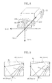
- the camera direction is to be defined. It is a common practice to determine a camera direction by combining the rotations around the X axis, Y axis and Z axis of the space defining coordinates system as shown in Fig. 5.
- the rotations around the X, Y and Z axes are respectively called tilt, pan, and twist.
- Clockwise rotation of each axis is represented by a positive angle, while counterclockwise rotation of each axis is represented by a negative angle.
- the camera direction obtained by conducting the rotating operations shown in Fig. 6(a), Fig. 6(b), Fig. 6(c) in this order, is represented in the form of tilt, pan, and twist.
- the camera direction in the coordinate system can be uniquely determined.
- it is required to adjust, in addition to the tilt, two other angles, i.e., the pan and the twist, unlike in the adjustment of a single camera.
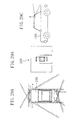
- Fig. 7 shows an example of the ranges to be captured and the images captured when the twin-camera 23 shown in Fig. 4 is mounted on the vehicle rear trunk.
- the item 1 is the condition for assuring the visual field just behind the vehicle. Particularly, when the cameras are disposed in the form of a twin-camera, the center line BCL must overlappingly be captured by each of the two cameras 23L, 23R. Otherwise, when the respective rear images are synthesized, there is formed a blank at the rear center part of the synthesized image, introducing a serious problem in view of safety. It is therefore desired that the center line BCL is seen as far away as possible by each of the two cameras 23L, 23R.
- the item 2 is the condition for assuring the visual field just beside the vehicle
- the item 3 is the condition for assuring the visual field just below and just behind the vehicle.
- the camera direction can efficiently be determined.
- each camera direction may be determined such that 1. the length P0-P1 is as long as possible, 2. the length P0-P2 is as long as possible, and 3. S is minimized when quantitatively expressing the three condition items mentioned earlier.
- the following evaluation value is for example introduced: Length P0-P1 x Length P0-P2 x 1/S
- the evaluation value above-mentioned may be evaluated only according to the camera direction (tilt, pan, twist) shown in Figs. 5 and 6. More specifically, while mutually independently changing the three kinds of angles forming the camera direction, i.e., the tilt, pan, and twist around the optical axis, the evaluation values are calculated, and based on the evaluation values thus calculated, the optimum camera direction (tilt, pan, twist) can be obtained.
- Fig. 10 is an example of the calculation results of evaluation values.
- a camera having a field of view of 110 ° is mounted, in the world coordinates system in Fig. 7, at a position of the coordinates (3 cm, 20 cm, -1 m), i.e., 3 cm in the positive cm, 20 cm, -1 m), i.e., 3 cm in the positive direction of the X axis from the origin 0, 20 cm in the positive direction of the Y axis and 1 m in the negative direction of the Z axis (1 m in height).
- Fig. 10 shows the results of the evaluation values calculated with respect to three different tilts while the pan is changed from 5° to 45° and the twist around the camera optical axis is changed from -30° to 30° .
- a plane parallel to the optical axes of the two cameras 23L, 23R is defined as a camera installation plane.
- the angle of divergence corresponds to an angle twice the pan above-mentioned. More specifically, the angle of divergence is preferably in the range not less than 50° and not greater than 90°.
- a plane at a right angle to the optical axis of a camera is defined as a reference plane. Then, there is considered the relationship between the u axis of a u-v plane of the camera visual field range at the time when the u-v plane is projected on the reference plane, and the intersecting line of the reference plane and the camera installation plane.
- the twist is not adjusted, i.e., when the twist is 0°, the projected u axis is parallel to the intersecting line of the reference plane and the camera installation plane.
- the twist around the optical axis of each camera is preferably set such that the u axis projected on the reference plane and the intersecting line of the reference plane and the camera installation plane, are not parallel to each other but intersect each other at a certain angle.
- the twist around the optical axis of each camera is preferably set such that the u axis projected on the reference plane is not parallel to and does not intersect, at a right angle, the intersecting line of the reference plane and the camera installation plane.
- the results above-mentioned show that a high evaluation value is obtained in the range of the twist from -35° ⁇ -10° for one camera and from 10° - 35° for the other camera.
- the twin-camera is preferably set such that the projected u axis and the intersecting line of the reference plane and the camera installation plane, intersect each other at an angle in the range not less than 10° and not greater than 35° .
- the camera direction is determined with the use of the evaluation value above-mentioned, but this evaluation value may be changed by other standard according to the object. For example, when it is enough to see only the close vicinity just behind the vehicle in the rear direction, the importance of the condition 1 is lowered. In such a case, the weight of "the length P0-P1" in the evaluation value may be reduced.
- the posture of a camera for monitoring the vehicle in a rear direction can also be determined by a similar method. More specifically, a straight line indicating the capturing direction may be supposed instead of the vehicle center line BCL, and a straight line extending along the vehicle end may be supposed instead of the vehicle rear-end line BEL. Then, by evaluating data in a manner similar to that in the embodiment above-mentioned, a suitable camera direction may be determined.
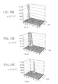
- Fig. 11(a) and Fig. 11(b) are conceptual views illustrating how the visual field range is changed according to the rotation of the camera around its optical axis.
- Fig. 11(a) shows the case where the twist is 0 ° (no rotation around the optical axis), while
- Fig. 11(b) shows the case where the twist is 33.2°.
- one camera 23L of the twin-camera is shown.
- the camera 23L has a field of view of 111° and is positioned at the coordinates (3 cm, 10 cm, -1 m) with the tilt set to 40° and the pan set to 30° .
- Fig. 11(a) the camera can see only 11 m in the transverse direction at the vehicle rear end (vehicle rear-end line BEL ) and only 4.4 m just in the rear direction at the vehicle longitudinal center (vehicle center line BCL ).
- Fig. 11(b) the camera can see a place which reaches the horizon HL in each of the transverse direction at the vehicle rear end and the rear direction at the vehicle longitudinal center. It is understood that the visual field can considerably be enlarged only by changing the twist even though other conditions than the twist are the same. It is considered that such change is caused due to the fact that the camera visual field range is square. The difference in visual field range results in a greater difference when a virtual visual point image is synthesized.
- Fig. 12(a) and Fig. 12(b) are views illustrating the virtual visual point images obtained at the time when the twist is 0° as shown in Fig. 11(a)
- Fig. 13(a) and Fig. 13(b) are views illustrating the virtual visual point images obtained at the time when the twist is 33.2° as shown in Fig. 11(b).
- Fig. 12(a) and Fig. 12(b) are views illustrating the virtual visual point images obtained at the time when the twist is 0° as shown in Fig. 11(b).
- the range of the visual field is considerably changed by adjusting the twist around the optical axis of the camera. This considerably changes the range of the vehicle surrounding to be displayed as a virtual visual point image. More specifically, to properly set the twist around the optical axis of each camera, is very important in a twin-camera for determining the performance of the monitoring system.
- twin-camera two cameras forming a pair are disposed in close vicinity to each other.
- the distance between the cameras is preferably as small as possible.
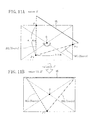
- Fig. 14(a) and Fig. 14(b) are views illustrating virtual visual point images, as viewed from above, which are obtained by synthesizing the images captured by the twin-camera.
- Fig. 14(a) shows the case where the two cameras 23L, 23R are disposed in close vicinity to each other, while
- Fig. 14(b) shows the case where the two cameras 23L, 23R are disposed with a small distance provided therebetween. Shown in Fig.
- an area VAL where only the image of the camera 23L is used
- an area VAR where only the image of the camera 23R is used
- an area VAB where the images of the two cameras 23L, 23R are synthesized
- a pole P just behind the vehicle an image PIL which is the image of the pole P synthesized from the image of the camera 23L
- an image PIR which is the image of the pole P synthesized from the image of the camera 23R.
- Fig. 14(a) and Fig. 14(b) are different from each other in that the pole P is included or not included in the area VAB in the synthesized image. More specifically, in Fig. 14(a), the pole images PIL, PIR respectively captured by the two cameras 23L, 23R are included in the area VAB. On the other hand, in Fig. 14(b), the two cameras 23L, 23R are disposed as slightly separated from each other and therefore, the pole images PIL, PIR protrude from the area VAB in the synthesized image. As a result, only the base portion of the pole P is shown in the synthesized image, causing the image at the boundary to be unnatural.
- This embodiment can be applied not only to a vehicle monitoring system, but also to a monitoring system for other application. More specifically, the technical concept of this embodiment can readily be applied to any system as far as the system has a twin-camera composed of cameras forming a pair.
- the display mode of the vehicle outside display apparatus 10 shown in Fig. 1 is set to a rear wide visual field scene display mode.
- Fig. 15(a) and Fig. 15(b) are views of a vehicle 1 and its surrounding. That is, Fig. 15(a) is a plan view and Fig. 15(b) is a side view. Shown in Fig. 15 are a front window Front_w of the vehicle 1, a rear bumper Rear_Bp, a trunk Tr and white lines 3A, 3B, 3C drawn on the ground surface. A pedestrian 2 (infant) stands behind the vehicle 1 .
- two cameras C1, C2 forming a pair are disposed in close vicinity to each other at the rear part of the vehicle 1, the two cameras C1, C2 being turned slightly obliquely downward and rearwardly outward.
- a range to be captured RC1 by the camera C1 and a range to be captured RC2 by the camera C2.
- a straight line L1 divides, into two equal portions, the overlapping portions of the ranges to be captured RC1, RC2 of the cameras C1, C2, and a straight line Lh is horizontally drawn from the mounting position of the cameras C1, C2.
- the cameras C1, C2 are disposed such that each of the ranges to be captured by the cameras C1, C2 includes both a portion of the rear bumper Rear_Bp and a portion of the horizon which would be seen when it is supposed that the vehicle is present on a level ground where no obstacle exists.
- Fig. 16(a) shows the image TP1 captured by the camera C1
- Fig. 16(b) shows the image TP2 captured by the camera C2.
- clipping ranges RGN_01, RGN_02. As shown in Fig. 16, provision is made such that each of the clipping ranges RGN_01, RGN_02 includes the rear bumper Rear_Bp.
- Fig. 17 shows a virtual visual point image PP_1 displayed on the display 12.
- the virtual visual point is set such that the rear visual field is spread in a wide area in the vicinity of the trunk Tr of the vehicle 1.
- the image processing device 11 executes simultaneously a processing of preparing partial images by clipping the captured images TP1, TP2 while referring to the conversion table TBL1 (table for a rear scene display), a processing of deforming the partial images to a virtual visual point image PP_1, and a processing of synthesizing the partial images (including a boundary processing). Accordingly, the virtual visual point image PP_1 as shown in Fig. 17 is displayed on the display 12.
- the virtual visual point image PP_1 shows, on a single screen, a rear scene in a wide visual field, thus improving the visibility in the rear direction of the vehicle 1.
- the virtual visual point may be set at the front of or slightly above the front window Front_w.
- the rear scene of the vehicle viewed from a visual point different from the room mirror and the side mirrors can be displayed in a wide range, facilitating to make sure of succeeding vehicles and the like.
- the display mode of the vehicle outside display apparatus 10 shown in Fig. 1 is set to a rear surrounding ground display mode.
- the two cameras C1, C2 shown in the second embodiment are used as they are.
- the display mode of the vehicle outside display apparatus 10 can be switched from the rear wide visual field scene display mode to the rear surrounding ground display mode, and vice versa. Such switching can be made manually or automatically.
- the cameras C1, C2 are set such that each of the ranges to be captured by the cameras C1, C2 includes an area occupied at the time when the vehicle 1 is retreated at an optional wheel angle by a predetermined distance.
- this predetermined distance is preferably set to at least N1/N2 of the vehicle length (N1 is an integer not less than 2, N2 is an integer not less than 3, and N1 ⁇ N2). From the result of repeated tests conducted by the Inventor, it is found that when the predetermined distance is set to at least 3 m or 2/3 of the vehicle length, the driver can comfortably execute a backing operation for parallel parking, putting into a garage, tandem parking or the like.
- Fig. 16(a) and Fig. 16(b) show the images TP1, TP2 captured by cameras C1, C2. There are also shown clipping ranges RGN_03, RGN_04 according to the third embodiment.
- Fig. 19 shows a virtual visual point image PP_2 displayed on the display 12.
- the image processing device 11 executes simultaneously a processing of preparing partial images by clipping the captured images TP1, TP2 while referring to the conversion table TBL2 (table for the rear surrounding ground display), a processing of deforming the partial images to the virtual visual point image PP_2, and a processing of synthesizing the partial images (including a boundary processing).
- the virtual visual point image PP_2 as shown in Fig. 19 is displayed on the display 12.
- a vehicle figure M is displayed at the center of the display 12.
- the virtual visual point is present at an upper part of the vehicle. Therefore, the display 12 displays the virtual visual point image PP_2 in which the vehicle 1 and the surrounding ground behind the vehicle 1 are viewed from above. Accordingly, the driver can accurately grasp the distance between the vehicle 1 and an obstacle behind the same.
- the display mode of the vehicle outside display apparatus 10 shown in Fig. 1 is set to a lateral-side surrounding ground display mode.
- Fig. 21 is a plan view of a vehicle 1 and its surrounding. As shown in Fig. 21, four cameras C4 ⁇ C7 are disposed on the roof 14 of the vehicle 1. The cameras C4 ⁇ C7 are disposed at positions within 20 cm from the end edges of the roof 14 at the rear left position, the rear right position, the front right position and the front left position, respectively. The cameras C4, C5 are turned obliquely backward, while the cameras C6, C7 are turned obliquely forward. Shown in Fig. 21 are ranges RC4 ⁇ RC7 to be captured by the cameras C4 ⁇ C7 respectively, and white lines 3A, 3B, 3C, 3D drawn on the ground.
- Fig. 22(a) to Fig. 22(d) respectively show the images TP4 ⁇ TP7 respectively captured by the cameras C4 ⁇ C7. There are also shown clipping ranges RGN_05, RGN_06, RGN_07, RGN_08 of the captured images TP4 - TP7 of the cameras C4 ⁇ C7. As shown in Fig. 22, each of the captured images TP4 ⁇ TP7 includes any of the four corners of the vehicle 1.
- the captured image TP4 shown in Fig. 22(a) includes the trunk Tr, a rear window Rear_w, and a left side window L_w.
- the captured image TP5 shown in Fig. 22(b) includes the trunk Tr, a rear window Rear_w, and a right side window R_w.
- the captured image TP6 shown in Fig. 22(c) includes the bonnet Bn , a front window Front_w, and a right side window R_w.
- the captured image TP7 shown in Fig. 22(d) includes the bonnet Bn , a front window Front_w, and a left side window L_w.
- the cameras C4 ⁇ C7 are disposed at a high position of the vehicle 1, i.e., on the roof 14. This reduces cubic distortion of other vehicle, a pedestrian, a structure and the like around the vehicle 1 which are displayed on the display 12. Further, the installation of the cameras C4 ⁇ C7 in the vicinity of the end edges of the roof 14, reduces the blind zones generated by the body of the vehicle 1, enabling the surrounding ground to be displayed on the display 12 in a wider range. Wherein, the cameras C4 ⁇ C7 may be disposed at a roof pillar.
- the image processing device 11 shown in Fig. 1 executes simultaneously a processing of preparing partial images by clipping the captured images TP4 ⁇ TP7 while referring to the conversion table TBL3 (table for a lateral-side surrounding ground display), a processing of deforming the partial images to a virtual visual point image, and a processing of synthesizing the partial images (including a boundary processing). Accordingly, a virtual visual point image PP_3 as shown in Fig. 23 is displayed on the display 12. In Fig. 23, a vehicle figure M is displayed at the center of the display 12.
- blind zones D are formed at both lateral sides of the vehicle 1.
- the blind zone D at the left side can be eliminated by extending the field of views of the forwardly turned camera C7 and the rearwardly turned camera C4 such that the visual fields thereof overlap each other.
- the blind zone D at the right side can be eliminated by extending the field of views of the forwardly turned camera C6 and the rearwardly turned camera C5 such that the visual fields thereof overlap each other.
- the blind zones can also be eliminated by combining this embodiment with a fifth embodiment to be discussed later.
- the capturing means is disposed in the vicinity of the centers of the lateral sides of the vehicle such that the blind zone areas for example shown in the fourth embodiment are included in the range to be captured.
- the display mode of the vehicle outside display apparatus 10 shown in Fig. 1 is set to a lateral-side surrounding ground display assisting mode.
- Fig. 24 is a plan view illustrating a vehicle 1 and its surrounding. As shown in Fig. 24, cameras C8, C9 are disposed at the non-movable part of a left door mirror 15A of the vehicle 1, and cameras C10, C11 are disposed at the non-movable part of a right door mirror 15B of the vehicle 1 . Also shown in Fig. 24 are ranges RC8, RC9, RC10, RC11 to be captured by the cameras C8 ⁇ C11, respectively, and white lines 3A, 3B, 3C, 3D drawn on the ground surface.
- Fig. 25(a) to Fig. 25(d) respectively show the images TP8 ⁇ TP11 captured by the cameras C8 ⁇ C11. There are also shown clipping ranges RGN_09, RGN_10, RGN_11, RGN_12 of the captured images TP8 - TP11.
- the captured image TP8 shown in Fig. 25(a) includes the left side window L_w and the left side door knob L_dnb.
- the captured image TP9 shown in Fig. 25(b) includes the left front winker L_wn and the left front tire L_t.
- the captured image TP10 shown in Fig. 25(c) includes the right side window R_w and the right side door knob R_dnb.
- the captured image TP11 shown in Fig. 25(d) includes the right front winker R_wn and the right front tire R_t.
- blind zones DC4, DC7, DC5, DC6 of the cameras C4, C7, C5, C6 shown in the third embodiment are shown by hatched lines.
- the cameras C8 ⁇ C11 are disposed in the vicinity of the door mirrors 15A, 15B at the vehicle lateral sides, enabling the blind zones to be considerably reduced.
- the places which should be seen by the driver to make sure of the safety are substantially securely included in any of the captured images TP4 ⁇ TP11 of the cameras C4 ⁇ C11. As a result, there can be provided a vehicle outside display apparatus excellent in safety.
- the partial images in the predetermined ranges are clipped to form a virtual visual point image covering the entire range of the vehicle surrounding.
- the image processing device 11 shown in Fig. 1 executes simultaneously a processing of preparing partial images by clipping the captured images TP8 ⁇ TP11, a processing of deforming the partial images to a virtual visual point image and a processing of synthesizing the partial images (including a boundary processing). Accordingly, a virtual visual point image PP_4 as shown in Fig. 26 is displayed on the display 12. In Fig. 26, a vehicle figure M is displayed at the center of the display 12.
- a single virtual visual point there is prepared a single virtual visual point. Accordingly, there are prepared, on the same virtual visual point, both the images obtained from the cameras C8, C9 shown at the left side of the vehicle figure M and the images obtained from the cameras C10, C11 shown at the right side of the vehicle figure M.
- a plurality of virtual visual points may be set, and the image at the left side of the vehicle figure M may be prepared based on a virtual visual point set immediately above the cameras C8, C9 , while the image at the right side of the vehicle figure M may be prepared based on a virtual visual point set immediately above the cameras C10, C11.
- the cameras C8 ⁇ C11 may be disposed, instead of at the non-movable parts of the door mirrors, at the lateral sides of the vehicle, the window visors, the door knob mounting portions, or the like. In such an arrangement, too, there are produced effects similar to those of the fifth embodiment.
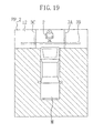
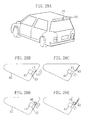
- Fig. 27(a) and Fig. 27(b) show an example of how the camera is mounted according to a sixth embodiment. Shown in Fig. 27(a) and Fig. 27(b) are a camera 31, a halogen lamp 32 serving as illumination means, and an openable member 33. The camera 31 is retractably disposed, and the openable member 33 forms a part of the vehicle body when closed.
- the camera 31 When not used, the camera 31 is in a housed state as shown in Fig. 27(a). On the other hand, for using the camera 31, the openable member 33 is opened, causing the camera 31 to be ejected to the outside of the vehicle as shown in Fig. 27(b).
- this sixth embodiment adopts the retractable mode to enable the camera to be ejected and housed. Accordingly, with the camera housed, the vehicle is neither lowered in aerodynamic characteristics nor injured in the beauty of vehicle design. On the other hand, the camera can be protected against dust and water drops.
- the camera may be installed together with an openable member such as a shutter or the like disposed at the front in the capturing direction.
- the camera is disposed as always housed in the vehicle body.
- the openable member may be adjusted such that the member is opened for using the camera and closed when the camera is not used.
- Fig. 28(a) to Fig. 28(e) are views illustrating openable cameras 41 disposed at rear wings 42.
- Fig. 28(a) shows the appearance of the whole body including the vehicle
- Fig. 28(b) and Fig. 28(c) show the arrangement for protecting the camera by a door-type openable member
- Fig. 28(d) and Fig. 28(e) show the arrangement for protecting the camera by a slide-type openable member.
- the opening and closing state of a shutter (protective lid) 43 is controlled by a lid opening/closing motor 44 in the same manner as a door is opened and closed
- Fig. 28(b) shows the closed state
- Fig. 28(c) shows the opening state
- the opening and closing state of a shutter (protective lid) 45 is controlled by a lid opening/closing motor 46 which slides the shutter 45 (Fig. 28(d) shows the closed state, while Fig. 28(e) shows the opening state).
- the camera may be disposed as housed in the vehicle body, and there may be disposed a transparent member such as a glass sheet at the front in the capturing direction.
- the camera 31 is disposed as corresponding to the halogen lamp 32 for irradiating light to the range to be captured by this camera 31.
- the camera 31 and the halogen lamp 32 are made in a unitary structure such that both the camera 31 and the halogen lamp 32 are ejected and housed at the same time.
- the illumination means may be disposed independently from the camera such that the light is irradiated to the range to be captured by the camera.
- the capturing means there may be used a camera having a capturing function of the infrared light detection type.
- the illumination means may be an infrared light source.
- red light emitting diodes may be attached to the tail lamp portions, or the tail lamps themselves may be red light emitting diodes.
- the camera 31 of the sixth embodiment when used as a camera disposed at the rear end of the vehicle as shown in the third embodiment, the camera 31 may be so arranged, for example, as to be ejected when the vehicle engine is turned on and the gear is set in the backing mode, and as to be housed when the gear is set in other mode than the backing mode.
- the camera 31 may be arranged in the following manner.
- the camera 31 may be ejected when the vehicle under normal travelling continuously travels at a predetermined speed (e.g., 50 Km/h) or more for a predetermined period of time or more, and the camera 31 may be housed when the vehicle continuously travels at a predetermined speed (e.g., 30 Km/h) or less for a predetermined period of time or more. It is a matter of course that the camera 31 may be ejected and housed manually.
- examples of the vehicle include an ordinary motor vehicle, a light motor car, an automobile truck, a bus and the like. Further, examples of the vehicle may also include a special vehicle such as a crane vehicle, an excavator and the like as far as the technical concept of the present invention can be applied thereto.
- the monitoring system according to the present invention is applied to a vehicle, but may similarly be applied to other moving body than a vehicle, such as an air plane, a ship and the like.
- the camera may be installed on other object than a moving body, such as a shop, a house, a show-room and the like.
- positions and number of a plurality of cameras are not limited to those shown in the embodiments above-mentioned.
Abstract
Description
- The present invention relates to technique effective for a monitoring system using a camera, which technique is utilized as an aide of making sure of the safety, or the like when driving a vehicle.
- There is conventionally known, as apparatus for actually capturing and monitoring the surrounding of a vehicle with the use of a camera, apparatus set forth in Japanese Patent Laid-Open Publication No. H3-99952. As shown in Fig. 29(a), this apparatus (vehicle surrounding situation monitor) is provided at the surrounding of a
vehicle 100 with a plurality of vehicle surrounding situation monitoring cameras (a - f). This apparatus is arranged such that partial images captured by the respective cameras are converted in plan elevation to form partial images in plan elevation, and that these partial images are synthesized to form a whole image in plan elevation as shown in Fig. 29(b), and that this whole image is displayed on a display (TV monitor) 200. - In the apparatus above-mentioned, however, the road monitoring cameras are not so arranged as to display even a rear scene. Accordingly, when intended to display a rear scene on the display at the time of backing operation, it is required to additionally dispose a rear monitoring camera g on the
vehicle 100, in addition to the road capturing cameras above-mentioned. - It is an object of the present invention to provide a monitoring system used for a vehicle or the like, which is improved in camera mounting posture and position, thereby to improve the monitoring performance as compared with a conventional monitoring system.
- More specifically, the present invention provides a monitoring system comprising a twin-camera composed of first and second cameras forming a pair, the first and second cameras being disposed such that at least portions of the ranges to be captured thereby overlap each other, and that the optical axes thereof form a predetermined angle of divergence when the optical axes are projected on a camera installation plane parallel to the optical axes, and the twist around the optical axis of at least one of the first and second cameras being set such that when a u-v plane of the visual field range of the at least one camera is projected on a reference plane at a right angle to the optical axis of the at least one camera, the u axis is not parallel to and does not intersect, at a right angle, the intersecting line of the reference plane and the camera installation plane.
- The twin-camera is preferably mounted on a vehicle for capturing both the surrounding of the vehicle and a place distant therefrom. Further, the twin-camera is preferably disposed such that the angle of divergence is not less than 50° and not greater than 90° , and that the twist is not less than 10° and not greater than 35° on the assumption that the twist is 0° when the u axis on the reference plane is parallel to the intersecting line of the reference plane and the camera installation plane.
- Preferably, each of the first and second cameras has a visual field range in the form of a square.
- The present invention provides a method of adjusting a twin-camera composed of a pair of cameras mounted on a vehicle for capturing both the surrounding of the vehicle and a place distant therefrom, this camera adjusting method being characterized in that the tilt, pan and twist around the optical axis of each of the pair of cameras, are adjusted using, as indexes, the length of a portion, as captured by each camera, of the straight line indicating the capturing direction, the length of a portion, as captured by each camera, of a straight line extending along the vehicle end, and the area of the blind zone in the capturing direction.
- The present invention provides a vehicle monitoring system comprising: a plurality of cameras for capturing the surrounding of a vehicle; and an image processing unit for generating, from the images captured by the plurality of cameras, a synthesized image viewed from a virtual view point, the plurality of cameras comprising a twin-camera composed of two cameras which form a pair and which are disposed in the close vicinity to each other.
- The twin-camera is preferably mounted in a unitary structure.
- The present invention provides a vehicle monitoring system comprising: one or a plurality of cameras for capturing the surrounding of a vehicle; and an image processing unit for generating, from the images captured by the one or plurality of cameras, a synthesized image viewed from a virtual view point, at least one of the one or plurality of cameras being mounted on the vehicle at its lateral side, a non-movable part of its door mirror, its window visor or its door knob mounting part.
- The present invention provides a vehicle monitoring system comprising: one or a plurality of cameras for capturing the surrounding of a vehicle; and an image processing unit for generating, from the images captured by the one or plurality of cameras, a synthesized image viewed from a virtual view point, at least one of the one or plurality of cameras being disposed as corresponding to illumination means for irradiating light to the range to be captured by the at least one camera.
- The present invention provides a vehicle monitoring system comprising: one or a plurality of cameras for capturing the surrounding of a vehicle; and an image processing unit for generating, from the images captured by the one or plurality of cameras, a synthesized image viewed from a virtual view point, at least one of the one or plurality of cameras being so retractably mounted on the vehicle as to be ejected when the camera is used, and as to be housed when the camera is not used.
- The retractable camera is preferably arranged such that its ejecting and housing is controlled according to at least one of the gear setting or travelling speed of the vehicle.
- The present invention provides a vehicle monitoring system comprising: one or a plurality of cameras for capturing the surrounding of a vehicle; and an image processing unit for generating, from the images captured by the one or plurality of cameras, a synthesized image viewed from a virtual view point, at least one of the one or plurality of cameras being mounted on the vehicle together with an openable member disposed at the front in the capturing direction of the at least one camera, the openable member being so controlled as to be opened when the camera is used, and as to be closed when the camera is not used.
-
- Fig. 1(a) and Fig. 1(b) are views respectively illustrating the arrangements of vehicle monitoring systems according to embodiments of the present invention;
- Fig. 2 is a view for illustrating a conversion table used in each of the vehicle monitoring systems in Fig. 1;
- Fig. 3 is a view illustrating how a rear monitoring camera is mounted in prior art;
- Fig. 4 is a view illustrating how a twin-camera according to a first embodiment of the present invention is mounted;
- Fig. 5 is a view illustrating the relationship between the tilt, pan and twist representing the camera direction, and the XYZ axes of the coordinates system which defines the space;
- Fig. 6(a) to Fig. 6(c) are views illustrating the rotating operations to be conducted for determining the tilt, pan and twist representing the camera direction;
- Fig. 7 shows an example of the ranges to be captured and the images captured when the twin-camera shown in Fig. 4 is mounted on the vehicle rear trunk;
- Fig. 8 is a view illustrating a world coordinates system used when mounting the camera;
- Fig. 9 shows views for illustrating an evaluation value according to the first embodiment of the present invention;
- Fig. 10(a) to Fig. 10(c) are views illustrating examples of calculation results of evaluation value;
- Fig. 11(a) and Fig. 11(b) are conceptual views illustrating how the visual field range is changed according to the rotation of the camera around its optical axis;
- Fig. 12(a) and Fig. 12(b) are views illustrating virtual visual point images obtained at the time when the twist is 0° as shown in Fig. 11(a);
- Fig. 13(a) and Fig. 13(b) are views illustrating virtual visual point images obtained at the time when the twist is 33.2° as shown in Fig. 11(b);
- Each of Fig. 14(a) and Fig. 14(b) is a view illustrating a virtual visual point image, as viewed from above, which is obtained by synthesizing the images captured by the twin-camera;
- Fig. 15(a) and Fig. 15(b) are views of a vehicle and its surrounding for illustrating second and third embodiments of the present invention, in which Fig. 15(a) is a plan view and Fig. 15(b) is a side view;
- Fig. 16(a) and Fig. 16(b) are views illustrating images captured by the respective cameras shown in Fig. 15;
- Fig. 17 is a virtual visual point image formed with the use of the captured images in Fig. 16;
- Fig. 18(a) and Fig. 18(b) are views for illustrating the third embodiment of the present invention, and show the images captured by the respective cameras shown in Fig. 15;
- Fig. 19 is a virtual visual point image formed with the use of the captured images in Fig. 18;
- Fig. 20(a) and Fig. 20(b) are views illustrating the third embodiment of the present invention in which three cameras are mounted;
- Fig. 21 is a plan view of a vehicle and its surrounding according to a fourth embodiment of the present invention;
- Fig. 22(a) to Fig. 22(d) are views illustrating the images captured by the respective cameras shown in Fig. 21;
- Fig. 23 is a virtual visual point image formed with the use of the captured images in Fig. 22;
- Fig. 24 is a plan view of a vehicle and its surrounding according to a fifth embodiment of the present invention;
- Fig. 25(a) to Fig. 25(d) are views illustrating the images captured by the respective cameras shown in Fig. 24;
- Fig. 26 is a virtual visual point image formed from the captured images in Fig. 25;
- Fig. 27(a) and Fig. 27(b) show an example of how a camera is mounted according to a sixth embodiment of the present invention, in which a retractable mode is adopted;
- Fig. 28(a) to Fig. 28(e) show another examples of how the camera is mounted according to the sixth embodiment of the present invention, in which an opening/closing mechanism is adopted; and
- Fig. 29(a) to Fig. 29(c) are views for illustrating technique of prior art.
-
- The following description will discuss embodiments of the present invention with reference to the attached drawings.
- Fig. 1(a) and Fig. 1(b) are functional block diagrams of vehicle outside display apparatus, serving as vehicle monitoring systems, according to embodiments of the present invention. In Fig. 1(a), the vehicle outside
display apparatus 10 comprises: a plurality of color CCD cameras C1 ∼ Cn serving as capturing means to be mounted on a plurality of positions of a vehicle; an image processing device 11 which receives captured images TP1 - TPn from the cameras C1 ∼ Cn, and which processes and supplies these captured images TP1 ∼ TPn as virtual visual point image data PP_D; and a liquid-crystal display 12 which receives the data PP_D and displays a virtual visual point image PP. The image processing device 11 executes processings on the captured images TP1 ∼ TPn with the use of any of conversion tables TBL1 ∼ TBLm. - Typically, the capturing means is a color or monochrome digital camera having a solid-state pickup element such as a CCD, CMOS device or the like. The capturing means may be formed for example by a combination of a lens and a prism or a mirror, and may be arranged such that light incident upon the lens, the prism or the mirror passes through a predetermined optical passage and is transmitted to a pickup element disposed at a position remote from the capturing means.
- The camera may have two or more mounting postures (such that the camera direction can be changed), or may be arranged such that the range to be captured is changed by a zooming operation or the like. It is a matter of fact that when the camera is changed in mounting posture and the range to be captured, the image processing device 11 suitably executes a different processing.
- The image processing device 11 may be mounted on the vehicle or may be disposed at a place other than the vehicle. In the latter case, the image data from the capturing means are transmitted in a wireless manner to an image processing device outside of the vehicle, and this image processing device executes a predetermined processing on the received image data to form a virtual visual point image, and sends this virtual visual point image thus formed to the display mounted on the vehicle.
- Typically, the display is a liquid-crystal display, but may be other display device such as a plasma display or the like. The display may also serve as a vehicle-mounted GPS terminal display (a display of a so-called car navigation system), or may be disposed independently therefrom.
- The display mode of the vehicle outside
display apparatus 10, is determined according to the conversion table used by the image processing device 11. The display mode may be switched manually or automatically. Examples of the processing to be executed by the image processing device 11, include 1 ○ a clipping processing, 2 ○ an image deforming processing, and 3 ○ a processing of synthesizing the clipped partial images (including a boundary processing). - The term "clipping" means cutting, from the captured image, a part required for synthesizing a virtual visual point image. The term "boundary processing" means a processing of hiding the boundary between adjacent partial images or a processing of causing the boundary between adjacent partial images to be not noticeable. More specifically, to hide or cause the boundary between adjacent partial images to be not noticeable, the adjacent partial images may be, for example, partially put one upon another at the boundary portions thereof, and there may be used a method of smoothing the change in at least one of brightness, chroma and hue of the overlapping portions at the boundary. It is a matter of course that the boundary between adjacent partial images may be marked clearly by a division line.
- These
processings 1 ○ ∼ 3 ○ may be executed respectively individually, or the whole or a portion of theseprocessings 1 ○∼3 ○ may be executed at one step. The clipping and synthesizing processings may be executed after the deforming processing has been executed on the captured images, or the deforming and synthesizing processings may be executed after the clipping processing has been executed. For example, when the pickup element is a CCD, the clipping processing can be executed after the captured image has been taken into a frame buffer. When the pickup element is a CMOS device, a portion to be clipped can be designated at the time of capturing, and the clipped image can be taken into the frame buffer. - The
display 12 displays a vehicle figure M formed by computer graphics. This vehicle figure M represents a vehicle image viewed from the virtual visual point. However, thedisplay 12 does not always display the vehicle figure M viewed from the virtual visual point. - Fig. 2 is a view illustrating an example of the conversion table. Fig. 2 shows the relationships between the pixel coordinates (i, j) of the virtual visual point image PP and the mapping data.
- More specifically, the conversion table is used for converting the pixel coordinates of a partial image into the pixel coordinates of the virtual visual point image. Dependent on the position of the virtual visual point, the camera mounting position and the like, the pixel coordinates of a partial image correspond to the pixel coordinates of the virtual visual point image on the basis of 1:1 or a plural number:1. For example, when the boundary processing is executed on the boundary between partial images, the pixel coordinates of a partial image do not always correspond to the pixel coordinates of the virtual visual point image on the basis of 1:1.
- In Fig. 2, the coordinates (i1, j1) represent the pixel to which the partial image captured by a camera Cp (p is any of 1 - n) corresponds, and there are prepared, as the mapping data corresponding to this pixel, the XY coordinates in the partial image captured by the camera Cp. The coordinates (i2, j2) represent the pixel which is equivalent to the boundary at which the partial image captured by the camera Cp overlaps the partial image captured by a camera Cq (q is any of 1 - n except p), and there are prepared, as the mapping data, the XY coordinates and the necessity degree of the partial images captured by the cameras Cp and Cq. In such a case, the pixel value of the coordinates (i2, j2) can be expressed for example in the following manner:
- Fig. 1(b) shows the arrangement in which the conversion tables TBL1 ∼ TBLm are disposed in an
image processing device 11A. A processor (not shown) in theimage processing device 11A refers to any of the conversion tables TBL1 ∼ TBLm. - More specifically, the conversion tables TBL1 ∼ TBLm shown in Fig. 1 are being written in a ROM (including a writing and erasable ROM such as an EEPROM or the like) or a RAM. The conversion tables may be generated by a processor in the image processing device 11 which calculates conversion table data and writes the data thus calculated in the RAM or ROM. Alternatively, the conversion tables may be generated by writing the conversion table data supplied as firmware in the RAM or ROM with the use of data transmission means such as a communication circuit, a disk drive or the like.
- As to each of the images captured by the cameras C1 ∼ Cn, it is possible to previously set the range to be clipped and to previously determine this range to be clipped based on the clipping reference point.
- The function of the image processing device may wholly or partially be achieved with the use of a dedicated hardware or software. It is also possible to utilize a recording medium or transmission medium which stores a program for causing the computer to execute the whole or partial function of the image processing device.
- The following description will discuss embodiments of the present invention. For convenience's sake, each camera, the human body and the like are shown in illustration although these should originally be shown in photograph.
- Fig. 3 is a view illustrating how a rear monitoring camera is mounted in prior art. To monitor in more detail the vehicle in the rear direction, it is desired to capture a range as broad as possible from the vicinity just behind the vehicle to a place distant therefrom. In this connection, a camera having a very wide visual field of which field of view exceeds 110° , is recently increasingly used as capturing means for monitoring the vehicle in the rear direction. As shown in Fig. 3, however, even with a wide-angle camera, blind zones D deviating from the range to be captured are inevitably generated at both sides just behind a
vehicle 21 as far as the field of view of the camera is smaller than 180°. Particularly, when those portions DS of the blind zones D located at inner parts with respect to the vehicle width, cannot be seen, an object present in the portions DS cannot be recognized on the captured image. This introduces the danger of causing trouble in view of safety when the vehicle travels in the backward. - To solve the problem above-mentioned, there is generally proposed a method of using, as the capturing means, a camera using a lens, for example a fisheye lens, having an ultra wide visual field of 180 ° or more. However, this method is disadvantageous in that the cost is increased because the precision required for lens machining is very high, and that a fine resolution cannot be obtained because the range to be captured is too wide. Thus, this method is encountered by many problems before being put into practical use. Accordingly, as compared with the use of an ultra-wide visual field camera, it is considered more effective in view of cost and resolution to use a pair of two cameras in order to obtain a visual field of 180° in the left and right directions.
- Fig. 4 is a conceptual view illustrating a mode of mounting, as a pair, two
cameras cameras camera 23 are disposed such that a visual field of 180 ° is obtained, that the twocameras - When mounting, on a vehicle, the cameras having the arrangement above-mentioned, it is very important in which directions the cameras forming a pair are disposed.
- When only one camera is mounted as a rearward monitoring capturing means as conventionally done, the camera can be situated substantially in the optimum position by a simple method of first turning the camera just in the rear direction of the vehicle and adjusting the tilt thereof according to the application. More specifically, when a single camera is used, the adjustment is simple because it is enough to determine only the tilt of the camera.
- In a twin-camera, the adjustment of the cameras forming the twin-camera is complicated as compared with a single camera. More specifically, it is not required to independently adjust the postures of the respective cameras forming the twin-camera, but it is required to adjust the optimum postures of the respective cameras while making sure of both the range to be captured by one camera and the range to be captured by the other camera. Making sure of the ranges to be captured by the two cameras, means, for example, making sure that the range to be captured by one camera does not overlap too much the range to be captured by the other camera, and making sure that there is no place which is not captured by either camera.
- This embodiment discloses a method of setting the postures of the respective cameras forming the twin-camera as shown in Fig. 4.
- First, the camera direction is to be defined. It is a common practice to determine a camera direction by combining the rotations around the X axis, Y axis and Z axis of the space defining coordinates system as shown in Fig. 5. In this specification, the rotations around the X, Y and Z axes are respectively called tilt, pan, and twist. Clockwise rotation of each axis is represented by a positive angle, while counterclockwise rotation of each axis is represented by a negative angle. The camera direction obtained by conducting the rotating operations shown in Fig. 6(a), Fig. 6(b), Fig. 6(c) in this order, is represented in the form of tilt, pan, and twist.
- By these three kinds of angles(tilt, pan, twist), the camera direction in the coordinate system can be uniquely determined. In other words, to optimize each camera direction in a twin-camera, it is required to adjust, in addition to the tilt, two other angles, i.e., the pan and the twist, unlike in the adjustment of a single camera.
- Fig. 7 shows an example of the ranges to be captured and the images captured when the twin-
camera 23 shown in Fig. 4 is mounted on the vehicle rear trunk. - The conditions for capturing a possibly broad range from the surrounding just behind the vehicle to a place distant therefrom in order to monitor the vehicle in the rear direction, are described in the following three items when qualitatively expressed with the use of the images of the two
cameras - 1. The vehicle center line BCL should be seen in the rear direction as far as possible (up to the horizon if possible).
- 2. The vehicle rear-end line BEL should be seen in the vehicle transverse directions as far as possible (up to the horizon if possible).
- 3. The blind zone S behind the vehicle should be minimized.
-
- The
item 1 is the condition for assuring the visual field just behind the vehicle. Particularly, when the cameras are disposed in the form of a twin-camera, the center line BCL must overlappingly be captured by each of the twocameras cameras item 2 is the condition for assuring the visual field just beside the vehicle, and the item 3 is the condition for assuring the visual field just below and just behind the vehicle. - Accordingly, when it is possible to calculate the degree at which each of the three conditions above-mentioned is satisfied, the camera direction can efficiently be determined.
- In this connection, to numerically evaluate the three condition items above-mentioned, a world coordinates system as shown in Fig. 8 is introduced. In this coordinates system, the respective axes are defined as set forth below:
- X-axis: the line, as projected on the road surface, of the boundary between the road surface viewed by a camera and the vehicle bumper, on the assumption that the bumper is linear.
- Y-axis: the vehicle longitudinal center line on the road surface
- Z-axis: the line which is perpendicular to the road surface and which passes through the intersecting point of the X and Y axes.
-
- In the coordinates system thus defined, the three items above-mentioned can quantitatively be evaluated with the use of the following indexes:
- 1. The distance from the origin point to the remotest rear point which can be seen. In Fig. 9, this distance corresponds to the length of a portion P0-P1, as captured by a camera, of the vehicle center line BCL.
- 2. The distance from the origin point to the remotest transverse point which can be seen. In Fig. 9, this distance corresponds to the length of a portion P0-P2, as captured by a camera, of the vehicle rear-end line BEL.
- 3. The area of the blind zone S just behind the vehicle.
-
- Accordingly, each camera direction may be determined such that 1. the length P0-P1 is as long as possible, 2. the length P0-P2 is as long as possible, and 3. S is minimized when quantitatively expressing the three condition items mentioned earlier. To evaluate the three items collectively, the following evaluation value is for example introduced:
P2 x 1/S - When P1, P2 are positioned on the horizon, the length P0-P1 and the length P0-P2 are infinite. Accordingly, sufficiently large values are previously determined as the upper limits of the length P0-P1 and the length P0-P2.
- When mounting the cameras on the vehicle, it is supposed that the camera mounting position has substantially no degree of freedom with the vehicle body design taken into consideration. Accordingly, at a predetermined mounting position, the evaluation value above-mentioned may be evaluated only according to the camera direction (tilt, pan, twist) shown in Figs. 5 and 6. More specifically, while mutually independently changing the three kinds of angles forming the camera direction, i.e., the tilt, pan, and twist around the optical axis, the evaluation values are calculated, and based on the evaluation values thus calculated, the optimum camera direction (tilt, pan, twist) can be obtained.
- Fig. 10 is an example of the calculation results of evaluation values. In Fig. 10, it is supposed that a camera having a field of view of 110 ° is mounted, in the world coordinates system in Fig. 7, at a position of the coordinates (3 cm, 20 cm, -1 m), i.e., 3 cm in the positive cm, 20 cm, -1 m), i.e., 3 cm in the positive direction of the X axis from the
origin - From the test results including the example in Fig. 10, it is understood that a high evaluation value is obtained in the range of the pan from about 25 ° ∼ about 45° and in the range of the twist from about -35° ∼ about -10° . According to the tests conducted by the Inventor of this application, it is found that the highest evaluation value is obtained with the tilt of about 40° .
- A plane parallel to the optical axes of the two
cameras cameras cameras - A plane at a right angle to the optical axis of a camera is defined as a reference plane. Then, there is considered the relationship between the u axis of a u-v plane of the camera visual field range at the time when the u-v plane is projected on the reference plane, and the intersecting line of the reference plane and the camera installation plane. When the twist is not adjusted, i.e., when the twist is 0°, the projected u axis is parallel to the intersecting line of the reference plane and the camera installation plane.
- More specifically, in a twin-camera, the twist around the optical axis of each camera is preferably set such that the u axis projected on the reference plane and the intersecting line of the reference plane and the camera installation plane, are not parallel to each other but intersect each other at a certain angle. Dependent on how to define the u-v coordinates of the camera visual field range, there are instances where the projected u axis intersects, at a right angle, the intersecting line of the reference plane and the camera installation plane, even though the twist is equal to 0°. Accordingly, strictly speaking, the twist around the optical axis of each camera is preferably set such that the u axis projected on the reference plane is not parallel to and does not intersect, at a right angle, the intersecting line of the reference plane and the camera installation plane.
- Further, the results above-mentioned show that a high evaluation value is obtained in the range of the twist from -35° ∼ -10° for one camera and from 10° - 35° for the other camera. This means that the twin-camera is preferably set such that the projected u axis and the intersecting line of the reference plane and the camera installation plane, intersect each other at an angle in the range not less than 10° and not greater than 35° .
- According to this embodiment, the camera direction is determined with the use of the evaluation value above-mentioned, but this evaluation value may be changed by other standard according to the object. For example, when it is enough to see only the close vicinity just behind the vehicle in the rear direction, the importance of the
condition 1 is lowered. In such a case, the weight of "the length P0-P1" in the evaluation value may be reduced. - In the foregoing, the description has been made of how to determine the posture of a camera for monitoring the vehicle in a rear direction. However, the posture of a camera for monitoring the vehicle in a transverse direction or in a front direction, can also be determined by a similar method. More specifically, a straight line indicating the capturing direction may be supposed instead of the vehicle center line BCL, and a straight line extending along the vehicle end may be supposed instead of the vehicle rear-end line BEL. Then, by evaluating data in a manner similar to that in the embodiment above-mentioned, a suitable camera direction may be determined.
- In adjustment of the posture of a twin-camera, setting of the twist around the optical axis of each camera is very important. The following will discuss the result of study of the Inventor on the reason of why such setting is important.
- Fig. 11(a) and Fig. 11(b) are conceptual views illustrating how the visual field range is changed according to the rotation of the camera around its optical axis. Fig. 11(a) shows the case where the twist is 0 ° (no rotation around the optical axis), while Fig. 11(b) shows the case where the twist is 33.2°. In Fig. 11, one
camera 23L of the twin-camera is shown. Thecamera 23L has a field of view of 111° and is positioned at the coordinates (3 cm, 10 cm, -1 m) with the tilt set to 40° and the pan set to 30° . - Now comparison is made between Fig. 11(a) and Fig. 11(b). In Fig. 11(a), the camera can see only 11 m in the transverse direction at the vehicle rear end (vehicle rear-end line BEL) and only 4.4 m just in the rear direction at the vehicle longitudinal center (vehicle center line BCL). On the other hand, in Fig. 11(b), the camera can see a place which reaches the horizon HL in each of the transverse direction at the vehicle rear end and the rear direction at the vehicle longitudinal center. It is understood that the visual field can considerably be enlarged only by changing the twist even though other conditions than the twist are the same. It is considered that such change is caused due to the fact that the camera visual field range is square. The difference in visual field range results in a greater difference when a virtual visual point image is synthesized.
- Fig. 12(a) and Fig. 12(b) are views illustrating the virtual visual point images obtained at the time when the twist is 0° as shown in Fig. 11(a), and Fig. 13(a) and Fig. 13(b) are views illustrating the virtual visual point images obtained at the time when the twist is 33.2° as shown in Fig. 11(b). As shown in Fig. 12, only the range of 4.4 m from the vehicle just behind the same, is captured by the camera when its twist is 0° . Accordingly, a person standing at a position, in the vehicle rear direction, remote by more than 4.4 m from the vehicle, does not appear at all on the virtual visual point image. On the contrary, when the twist is 33.2°, the rear scene just behind the vehicle is reflected on the camera up to the horizon HL as shown in Fig. 13. Accordingly, a person standing at a position of about 5 m from the vehicle in the rear direction, can securely be reflected on the virtual visual point image.
- As discussed in the foregoing, the range of the visual field is considerably changed by adjusting the twist around the optical axis of the camera. This considerably changes the range of the vehicle surrounding to be displayed as a virtual visual point image. More specifically, to properly set the twist around the optical axis of each camera, is very important in a twin-camera for determining the performance of the monitoring system.
- In a twin-camera, two cameras forming a pair are disposed in close vicinity to each other. The distance between the cameras is preferably as small as possible.
- Fig. 14(a) and Fig. 14(b) are views illustrating virtual visual point images, as viewed from above, which are obtained by synthesizing the images captured by the twin-camera. Fig. 14(a) shows the case where the two
cameras cameras camera 23L is used, an area VAR where only the image of thecamera 23R is used, an area VAB where the images of the twocameras camera 23L, and an image PIR which is the image of the pole P synthesized from the image of thecamera 23R. - Fig. 14(a) and Fig. 14(b) are different from each other in that the pole P is included or not included in the area VAB in the synthesized image. More specifically, in Fig. 14(a), the pole images PIL, PIR respectively captured by the two
cameras cameras - From the study of the Inventor, it has been found that, when partial images are synthesized at the time the distance between the image forming points of the camera lenses is 20 cm or more, a shear in image at the boundary is increased, readily causing the image at the boundary to be unnatural. More specifically, when disposing a twin-camera, it is preferable to dispose the two cameras such that the image forming points thereof are not separated from each other by 20 cm or more. Further, the two cameras forming a twin-camera are preferably packaged in a unitary structure.
- This embodiment can be applied not only to a vehicle monitoring system, but also to a monitoring system for other application. More specifically, the technical concept of this embodiment can readily be applied to any system as far as the system has a twin-camera composed of cameras forming a pair.
- According to a second embodiment, it is supposed that the display mode of the vehicle outside
display apparatus 10 shown in Fig. 1 is set to a rear wide visual field scene display mode. - Fig. 15(a) and Fig. 15(b) are views of a
vehicle 1 and its surrounding. That is, Fig. 15(a) is a plan view and Fig. 15(b) is a side view. Shown in Fig. 15 are a front window Front_w of thevehicle 1, a rear bumper Rear_Bp, a trunk Tr andwhite lines vehicle 1. - As shown in Fig. 15, two cameras C1, C2 forming a pair are disposed in close vicinity to each other at the rear part of the
vehicle 1, the two cameras C1, C2 being turned slightly obliquely downward and rearwardly outward. There are also shown a range to be captured RC1 by the camera C1 and a range to be captured RC2 by the camera C2. A straight line L1 divides, into two equal portions, the overlapping portions of the ranges to be captured RC1, RC2 of the cameras C1, C2, and a straight line Lh is horizontally drawn from the mounting position of the cameras C1, C2. - As understood from Fig. 15(b), the cameras C1, C2 are disposed such that each of the ranges to be captured by the cameras C1, C2 includes both a portion of the rear bumper Rear_Bp and a portion of the horizon which would be seen when it is supposed that the vehicle is present on a level ground where no obstacle exists.
- Fig. 16(a) shows the image TP1 captured by the camera C1 and Fig. 16(b) shows the image TP2 captured by the camera C2. There are also shown clipping ranges RGN_01, RGN_02. As shown in Fig. 16, provision is made such that each of the clipping ranges RGN_01, RGN_02 includes the rear bumper Rear_Bp.
- Fig. 17 shows a virtual visual point image PP_1 displayed on the
display 12. In the image in Fig. 17, the virtual visual point is set such that the rear visual field is spread in a wide area in the vicinity of the trunk Tr of thevehicle 1. - According to the second embodiment, the image processing device 11 executes simultaneously a processing of preparing partial images by clipping the captured images TP1, TP2 while referring to the conversion table TBL1 (table for a rear scene display), a processing of deforming the partial images to a virtual visual point image PP_1, and a processing of synthesizing the partial images (including a boundary processing). Accordingly, the virtual visual point image PP_1 as shown in Fig. 17 is displayed on the
display 12. - According to the second embodiment, the virtual visual point image PP_1 shows, on a single screen, a rear scene in a wide visual field, thus improving the visibility in the rear direction of the
vehicle 1. In normal travelling or highspeed travelling, the virtual visual point may be set at the front of or slightly above the front window Front_w. In such a case, the rear scene of the vehicle viewed from a visual point different from the room mirror and the side mirrors, can be displayed in a wide range, facilitating to make sure of succeeding vehicles and the like. - According to a third embodiment, it is supposed that the display mode of the vehicle outside
display apparatus 10 shown in Fig. 1 is set to a rear surrounding ground display mode. In this embodiment, the two cameras C1, C2 shown in the second embodiment are used as they are. The display mode of the vehicle outsidedisplay apparatus 10 can be switched from the rear wide visual field scene display mode to the rear surrounding ground display mode, and vice versa. Such switching can be made manually or automatically. - According to the third embodiment, the cameras C1, C2 are set such that each of the ranges to be captured by the cameras C1, C2 includes an area occupied at the time when the
vehicle 1 is retreated at an optional wheel angle by a predetermined distance. Generally, this predetermined distance is preferably set to at least N1/N2 of the vehicle length (N1 is an integer not less than 2, N2 is an integer not less than 3, and N1<N2). From the result of repeated tests conducted by the Inventor, it is found that when the predetermined distance is set to at least 3 m or 2/3 of the vehicle length, the driver can comfortably execute a backing operation for parallel parking, putting into a garage, tandem parking or the like. - Likewise Fig. 16(a) and Fig. 16(b), Fig. 18(a) and Fig. 18(b) show the images TP1, TP2 captured by cameras C1, C2. There are also shown clipping ranges RGN_03, RGN_04 according to the third embodiment.
- Fig. 19 shows a virtual visual point image PP_2 displayed on the
display 12. According to the third embodiment, the image processing device 11 executes simultaneously a processing of preparing partial images by clipping the captured images TP1, TP2 while referring to the conversion table TBL2 (table for the rear surrounding ground display), a processing of deforming the partial images to the virtual visual point image PP_2, and a processing of synthesizing the partial images (including a boundary processing). Accordingly, the virtual visual point image PP_2 as shown in Fig. 19 is displayed on thedisplay 12. In Fig. 19, a vehicle figure M is displayed at the center of thedisplay 12. - When the ranges to be captured by the two cameras C1, C2 are too narrow to sufficiently display, on the screen, the ground around the rear of the
vehicle 1, another camera C3 may be added such that the total three cameras C1, C2, C3 are disposed at the rear of thevehicle 1 as shown in Fig. 20(a). Shown in Fig. 20(a) are the ranges to be captured RC1, RC2, RC3 of the cameras C1, C2, C3. By the addition of a camera, the range of the surrounding ground to be displayed can be enlarged. In such a case, too, it is preferable to dispose the cameras C1, C2, C3 such that each of the gaps among the image forming points thereof is not greater than 20 cm as shown in Fig. 20(b). - According to the third embodiment, the virtual visual point is present at an upper part of the vehicle. Therefore, the
display 12 displays the virtual visual point image PP_2 in which thevehicle 1 and the surrounding ground behind thevehicle 1 are viewed from above. Accordingly, the driver can accurately grasp the distance between thevehicle 1 and an obstacle behind the same. - According to a fourth embodiment, it is supposed that the display mode of the vehicle outside
display apparatus 10 shown in Fig. 1 is set to a lateral-side surrounding ground display mode. - Fig. 21 is a plan view of a
vehicle 1 and its surrounding. As shown in Fig. 21, four cameras C4 ∼ C7 are disposed on theroof 14 of thevehicle 1. The cameras C4 ∼ C7 are disposed at positions within 20 cm from the end edges of theroof 14 at the rear left position, the rear right position, the front right position and the front left position, respectively. The cameras C4, C5 are turned obliquely backward, while the cameras C6, C7 are turned obliquely forward. Shown in Fig. 21 are ranges RC4 ∼ RC7 to be captured by the cameras C4 ∼ C7 respectively, andwhite lines - Fig. 22(a) to Fig. 22(d) respectively show the images TP4 ∼ TP7 respectively captured by the cameras C4 ∼ C7. There are also shown clipping ranges RGN_05, RGN_06, RGN_07, RGN_08 of the captured images TP4 - TP7 of the cameras C4 ∼ C7. As shown in Fig. 22, each of the captured images TP4 ∼ TP7 includes any of the four corners of the
vehicle 1. - The captured image TP4 shown in Fig. 22(a) includes the trunk Tr, a rear window Rear_w, and a left side window L_w. The captured image TP5 shown in Fig. 22(b) includes the trunk Tr, a rear window Rear_w, and a right side window R_w. The captured image TP6 shown in Fig. 22(c) includes the bonnet Bn , a front window Front_w, and a right side window R_w. The captured image TP7 shown in Fig. 22(d) includes the bonnet Bn , a front window Front_w, and a left side window L_w.
- According to the fourth embodiment, the cameras C4 ∼ C7 are disposed at a high position of the
vehicle 1, i.e., on theroof 14. This reduces cubic distortion of other vehicle, a pedestrian, a structure and the like around thevehicle 1 which are displayed on thedisplay 12. Further, the installation of the cameras C4 ∼ C7 in the vicinity of the end edges of theroof 14, reduces the blind zones generated by the body of thevehicle 1, enabling the surrounding ground to be displayed on thedisplay 12 in a wider range. Wherein, the cameras C4 ∼ C7 may be disposed at a roof pillar. - According to the fourth embodiment, too, the image processing device 11 shown in Fig. 1 executes simultaneously a processing of preparing partial images by clipping the captured images TP4 ∼ TP7 while referring to the conversion table TBL3 (table for a lateral-side surrounding ground display), a processing of deforming the partial images to a virtual visual point image, and a processing of synthesizing the partial images (including a boundary processing). Accordingly, a virtual visual point image PP_3 as shown in Fig. 23 is displayed on the
display 12. In Fig. 23,a vehicle figure M is displayed at the center of thedisplay 12. - In Fig. 23, blind zones D are formed at both lateral sides of the
vehicle 1. The blind zone D at the left side can be eliminated by extending the field of views of the forwardly turned camera C7 and the rearwardly turned camera C4 such that the visual fields thereof overlap each other. The blind zone D at the right side can be eliminated by extending the field of views of the forwardly turned camera C6 and the rearwardly turned camera C5 such that the visual fields thereof overlap each other. Further, the blind zones can also be eliminated by combining this embodiment with a fifth embodiment to be discussed later. - According to a fifth embodiment, the capturing means is disposed in the vicinity of the centers of the lateral sides of the vehicle such that the blind zone areas for example shown in the fourth embodiment are included in the range to be captured. According to the fifth embodiment, the display mode of the vehicle outside
display apparatus 10 shown in Fig. 1 is set to a lateral-side surrounding ground display assisting mode. - Fig. 24 is a plan view illustrating a
vehicle 1 and its surrounding. As shown in Fig. 24, cameras C8, C9 are disposed at the non-movable part of aleft door mirror 15A of thevehicle 1, and cameras C10, C11 are disposed at the non-movable part of aright door mirror 15B of thevehicle 1. Also shown in Fig. 24 are ranges RC8, RC9, RC10, RC11 to be captured by the cameras C8 ∼ C11, respectively, andwhite lines - Fig. 25(a) to Fig. 25(d) respectively show the images TP8 ∼ TP11 captured by the cameras C8 ∼ C11. There are also shown clipping ranges RGN_09, RGN_10, RGN_11, RGN_12 of the captured images TP8 - TP11.
- The captured image TP8 shown in Fig. 25(a) includes the left side window L_w and the left side door knob L_dnb. The captured image TP9 shown in Fig. 25(b) includes the left front winker L_wn and the left front tire L_t. The captured image TP10 shown in Fig. 25(c) includes the right side window R_w and the right side door knob R_dnb. The captured image TP11 shown in Fig. 25(d) includes the right front winker R_wn and the right front tire R_t. In Fig. 25(a) - Fig. 25(d), blind zones DC4, DC7, DC5, DC6 of the cameras C4, C7, C5, C6 shown in the third embodiment, are shown by hatched lines.
- According to the fifth embodiment, the cameras C8 ∼ C11 are disposed in the vicinity of the door mirrors 15A, 15B at the vehicle lateral sides, enabling the blind zones to be considerably reduced. In this connection, by combining the fifth embodiment with the fourth embodiment above-mentioned, the places which should be seen by the driver to make sure of the safety, are substantially securely included in any of the captured images TP4 ∼ TP11 of the cameras C4 ∼ C11. As a result, there can be provided a vehicle outside display apparatus excellent in safety. For example, out of the captured images TP4 ∼ TP7 of the cameras C4 ∼ C7 shown in the fourth embodiment and the captured images TP8∼ TP11 of the cameras C8 ∼ C11 shown in the fifth embodiment, the partial images in the predetermined ranges are clipped to form a virtual visual point image covering the entire range of the vehicle surrounding.
- According to the fifth embodiment, too, the image processing device 11 shown in Fig. 1 executes simultaneously a processing of preparing partial images by clipping the captured images TP8 ∼ TP11, a processing of deforming the partial images to a virtual visual point image and a processing of synthesizing the partial images (including a boundary processing). Accordingly, a virtual visual point image PP_4 as shown in Fig. 26 is displayed on the
display 12. In Fig. 26, a vehicle figure M is displayed at the center of thedisplay 12. - According to the fifth embodiment, there is prepared a single virtual visual point. Accordingly, there are prepared, on the same virtual visual point, both the images obtained from the cameras C8, C9 shown at the left side of the vehicle figure M and the images obtained from the cameras C10, C11 shown at the right side of the vehicle figure M. However, a plurality of virtual visual points may be set, and the image at the left side of the vehicle figure M may be prepared based on a virtual visual point set immediately above the cameras C8, C9, while the image at the right side of the vehicle figure M may be prepared based on a virtual visual point set immediately above the cameras C10, C11.
- The cameras C8 ∼ C11 may be disposed, instead of at the non-movable parts of the door mirrors, at the lateral sides of the vehicle, the window visors, the door knob mounting portions, or the like. In such an arrangement, too, there are produced effects similar to those of the fifth embodiment.
- Fig. 27(a) and Fig. 27(b) show an example of how the camera is mounted according to a sixth embodiment. Shown in Fig. 27(a) and Fig. 27(b) are a
camera 31, ahalogen lamp 32 serving as illumination means, and anopenable member 33. Thecamera 31 is retractably disposed, and theopenable member 33 forms a part of the vehicle body when closed. - When not used, the
camera 31 is in a housed state as shown in Fig. 27(a). On the other hand, for using thecamera 31, theopenable member 33 is opened, causing thecamera 31 to be ejected to the outside of the vehicle as shown in Fig. 27(b). - More specifically, this sixth embodiment adopts the retractable mode to enable the camera to be ejected and housed. Accordingly, with the camera housed, the vehicle is neither lowered in aerodynamic characteristics nor injured in the beauty of vehicle design. On the other hand, the camera can be protected against dust and water drops.
- Instead of the retractable mode, the camera may be installed together with an openable member such as a shutter or the like disposed at the front in the capturing direction. In such a case, the camera is disposed as always housed in the vehicle body. The openable member may be adjusted such that the member is opened for using the camera and closed when the camera is not used.
- Fig. 28(a) to Fig. 28(e) are views illustrating
openable cameras 41 disposed atrear wings 42. Fig. 28(a) shows the appearance of the whole body including the vehicle, Fig. 28(b) and Fig. 28(c) show the arrangement for protecting the camera by a door-type openable member, and Fig. 28(d) and Fig. 28(e) show the arrangement for protecting the camera by a slide-type openable member. In the door type, the opening and closing state of a shutter (protective lid) 43 is controlled by a lid opening/closing motor 44 in the same manner as a door is opened and closed (Fig. 28(b) shows the closed state, while Fig. 28(c) shows the opening state). In the slide type, the opening and closing state of a shutter (protective lid) 45 is controlled by a lid opening/closing motor 46 which slides the shutter 45 (Fig. 28(d) shows the closed state, while Fig. 28(e) shows the opening state). - For conveniences' sake, the arrangement using a single camera is illustrated. However, it is a matter of course that a similar opening/closing mechanism can be applied to a twin-camera, too. Here, two types of shutter opening/closing mechanisms have been discussed, but the opening/closing operation may of course be achieved by other mechanism.
- The use of such an opening/closing mechanism produces, in addition to the effect produced by the adoption of a retractable mode, an effect of restraining the camera from being positionally shifted because of no change in camera physical position. In such a case, it is required to dispose the camera at a position which assures the desired visual field. For example, when there is disposed a camera for monitoring the place immediate below and just behind the vehicle, it is preferable to dispose the camera, as turned downward, inside of the
rear wing 42 as shown in Fig. 28(a). This position is not particularly noticeable. Further, therear wing 42 is already projecting rearward. Accordingly, without the special need to eject the camera for assuring the visual field, the desired visual field can readily be assured. However, when introducing such an opening/closing mechanism, it is required to design the configurations of the opening/closing mechanism and the shutter such that in the opening state, the camera visual field is not obstructed by the whole or a part of the shutter as opened. - Further, the camera may be disposed as housed in the vehicle body, and there may be disposed a transparent member such as a glass sheet at the front in the capturing direction.
- In Fig. 27, the
camera 31 is disposed as corresponding to thehalogen lamp 32 for irradiating light to the range to be captured by thiscamera 31. Thecamera 31 and thehalogen lamp 32 are made in a unitary structure such that both thecamera 31 and thehalogen lamp 32 are ejected and housed at the same time. It is a matter of course that the illumination means may be disposed independently from the camera such that the light is irradiated to the range to be captured by the camera. - As the capturing means, there may be used a camera having a capturing function of the infrared light detection type. In such a case, the illumination means may be an infrared light source. For example, red light emitting diodes may be attached to the tail lamp portions, or the tail lamps themselves may be red light emitting diodes. Such an arrangement can improve the visibility of a person, a structure and the like present in the range to be captured even though the surrounding of the vehicle is dark.
- Provision may be made such that the control of ejecting and housing the
camera 31 is automatically made according to the vehicle gear setting, the travelling speed or the like. - For example, when the
camera 31 of the sixth embodiment is used as a camera disposed at the rear end of the vehicle as shown in the third embodiment, thecamera 31 may be so arranged, for example, as to be ejected when the vehicle engine is turned on and the gear is set in the backing mode, and as to be housed when the gear is set in other mode than the backing mode. - When the
camera 31 of the sixth embodiment is used as a camera disposed as shown in the second embodiment, thecamera 31 may be arranged in the following manner. For example, thecamera 31 may be ejected when the vehicle under normal travelling continuously travels at a predetermined speed (e.g., 50 Km/h) or more for a predetermined period of time or more, and thecamera 31 may be housed when the vehicle continuously travels at a predetermined speed (e.g., 30 Km/h) or less for a predetermined period of time or more. It is a matter of course that thecamera 31 may be ejected and housed manually. - According to the present invention, examples of the vehicle include an ordinary motor vehicle, a light motor car, an automobile truck, a bus and the like. Further, examples of the vehicle may also include a special vehicle such as a crane vehicle, an excavator and the like as far as the technical concept of the present invention can be applied thereto.
- In the description above-mentioned, the monitoring system according to the present invention is applied to a vehicle, but may similarly be applied to other moving body than a vehicle, such as an air plane, a ship and the like. Further, the camera may be installed on other object than a moving body, such as a shop, a house, a show-room and the like.
- Further, the positions and number of a plurality of cameras are not limited to those shown in the embodiments above-mentioned.
Claims (12)
- A monitoring system comprising a twin-camera composed of first and second cameras forming a pair,
said first and second cameras being disposed such that at least portions of the ranges to be captured thereby overlap each other, and that the optical axes thereof form a predetermined angle of divergence when said optical axes are projected on a camera installation plane parallel to said optical axes,
the twist around the optical axis of at least one of said first and second cameras being set such that when an u-v plane of the visual field range of said at least one camera is projected on a reference plane at a right angle to the optical axis of said at least one camera, the u axis is not parallel to and does not intersect, at a right angle, the intersecting line of said reference plane and said camera installation plane. - A monitoring system according to Claim 1, wherein said twin-camera is mounted on a vehicle for capturing both the surrounding of said vehicle and a place distant therefrom.
- A monitoring system according to Claim 2, wherein said twin-camera is disposed such that said angle of divergence is not less than 50° and not greater than 90° , and that said twist is not less than 10° and not greater than 35° on the assumption that said twist is 0° when said u axis on said reference plane is parallel to said intersecting line of said reference plane and said camera installation plane.
- A monitoring system according to Claim 1, wherein each of said first and second cameras has a visual field range in the form of a square.
- A method of adjusting a twin-camera composed of a pair of cameras mounted on a vehicle for capturing both the surrounding of said vehicle and a place distant therefrom,
said camera adjusting method being characterized in that the tilt, pan and twist around the optical axis of each of said pair of cameras, are adjusted using, as indexes, the length of a portion, as captured by each camera, of the straight line indicating the capturing direction, the length of a portion, as captured by each camera, of a straight line extending along the vehicle end, and the area of the blind zone in the capturing direction. - A vehicle monitoring system comprising:said plurality of cameras comprising a twin-camera composed of two cameras which form a pair and which are disposed in the close vicinity to each other.a plurality of cameras for capturing the surrounding of a vehicle; andan image processing unit for generating, from the images captured by said plurality of cameras, a synthesized image viewed from a virtual view point,
- A vehicle monitoring system according to Claim 6, wherein said twin-camera is mounted in a unitary structure.
- A vehicle monitoring system comprising:at least one of said one or plurality of cameras being mounted on said vehicle at its lateral side, a non-movable part of its door mirror, its window visor or its door knob mounting part.one or a plurality of cameras for capturing the surrounding of a vehicle; andan image processing unit for generating, from the images captured by said one or plurality of cameras, a synthesized image viewed from a virtual view point,
- A vehicle monitoring system comprising:at least one of said one or plurality of cameras being disposed as corresponding to illumination means for irradiating light to the range to be captured by said at least one camera.one or a plurality of cameras for capturing the surrounding of a vehicle; andan image processing unit for generating, from the images captured by said one or plurality of cameras, a synthesized image viewed from a virtual view point,
- A vehicle monitoring system comprising:at least one of said one or plurality of cameras being so retractably mounted on said vehicle as to be ejected when said camera is used, and as to be housed when said camera is not used.one or a plurality of cameras for capturing the surrounding of a vehicle; andan image processing unit for generating, from the images captured by said one or plurality of cameras, a synthesized image viewed from a virtual view point,
- A vehicle monitoring system according to Claim 10, wherein said retractable camera is arranged such that its ejecting and housing is controlled according to at least one of the gear setting or travelling speed of said vehicle.
- A vehicle monitoring system comprising:at least one of said one or plurality of cameras being mounted on said vehicle together with an openable member disposed at the front in the capturing direction of said at least one camera,one or a plurality of cameras for capturing the surrounding of a vehicle; andan image processing unit for generating, from the images captured by said one or plurality of cameras, a synthesized image viewed from a virtual view point,
said openable member being so controlled as to be opened when said camera is used, and as to be closed when said camera is not used.
Applications Claiming Priority (3)
| Application Number | Priority Date | Filing Date | Title |
|---|---|---|---|
| JP28952999 | 1999-10-12 | ||
| JP28952999 | 1999-10-12 | ||
| PCT/JP2000/007062 WO2001028250A1 (en) | 1999-10-12 | 2000-10-12 | Monitor camera, method of adjusting camera, and vehicle monitor system |
Publications (3)
| Publication Number | Publication Date |
|---|---|
| EP1227683A1 true EP1227683A1 (en) | 2002-07-31 |
| EP1227683A4 EP1227683A4 (en) | 2003-06-25 |
| EP1227683B1 EP1227683B1 (en) | 2006-07-12 |
Family
ID=17744441
Family Applications (1)
| Application Number | Title | Priority Date | Filing Date |
|---|---|---|---|
| EP00966421A Expired - Lifetime EP1227683B1 (en) | 1999-10-12 | 2000-10-12 | Monitor camera, method of adjusting camera, and vehicle monitor system |
Country Status (8)
| Country | Link |
|---|---|
| US (1) | US6911997B1 (en) |
| EP (1) | EP1227683B1 (en) |
| JP (1) | JP3300341B2 (en) |
| KR (1) | KR100522218B1 (en) |
| CN (2) | CN1561093A (en) |
| AT (1) | ATE333192T1 (en) |
| DE (1) | DE60029335T2 (en) |
| WO (1) | WO2001028250A1 (en) |
Cited By (20)
| Publication number | Priority date | Publication date | Assignee | Title |
|---|---|---|---|---|
| WO2003051671A1 (en) * | 2001-12-19 | 2003-06-26 | Magna Auteca Ag | Electronic rearview system for vehicles |
| WO2003107067A2 (en) * | 2002-06-18 | 2003-12-24 | Bayerische Motoren Werke | Method and device for visualising the environment of a vehicle by merging an infrared image and a visual image according to distance |
| EP1302365A3 (en) * | 2001-10-15 | 2004-10-20 | Matsushita Electric Industrial Co., Ltd. | Vehicle surroundings monitoring system and method for adjusting the same |
| WO2005084028A2 (en) * | 2004-02-26 | 2005-09-09 | Bendix Commercial Vehicle Systems Llc | Vehicle video processing system |
| WO2006058606A1 (en) * | 2004-12-03 | 2006-06-08 | Valeo Schalter Und Sensoren Gmbh | File format for the organisation of data and control appliance |
| US7834905B2 (en) | 2002-06-18 | 2010-11-16 | Bayerische Motoren Werke Aktiengesellschaft | Method and system for visualizing the environment of a vehicle with a distance-dependent merging of an infrared and a visual image |
| WO2011023837A3 (en) * | 2009-08-24 | 2011-07-14 | Guillermo Canovas Garcia | Back rear-view mirror for vehicles |
| US8753025B2 (en) | 2011-07-26 | 2014-06-17 | Gentex Corporation | Imaging device protector and cleaner |
| EP2949511A1 (en) * | 2014-05-30 | 2015-12-02 | LG Electronics Inc. | Surround view vision apparatus and vehicle including the same |
| EP2974278A4 (en) * | 2013-03-15 | 2016-03-23 | Tolo Inc | Distortion correcting sensors for diagonal collection of oblique imagery |
| EP2560383A4 (en) * | 2010-04-12 | 2016-09-07 | Sumitomo Heavy Industries | Image generation device and operation support system |
| US9838653B2 (en) | 2011-06-24 | 2017-12-05 | Gentex Corporation | Roof mounted imager module |
| US9849836B2 (en) | 2014-04-24 | 2017-12-26 | Gentex Corporation | Roof mounted imager module |
| DE102007024752B4 (en) | 2007-05-26 | 2018-06-21 | Bayerische Motoren Werke Aktiengesellschaft | Method for driver information in a motor vehicle |
| US10012530B2 (en) | 2013-03-14 | 2018-07-03 | Gentex Corporation | Light sensing device |
| USD854600S1 (en) | 2016-12-16 | 2019-07-23 | Gentex Corporation | Imager housing |
| US10514590B2 (en) | 2017-03-30 | 2019-12-24 | Gentex Corporation | Switchable imager lens cover |
| US10981505B2 (en) | 2017-02-28 | 2021-04-20 | Gentex Corporation | Auto switching of display mirror assembly |
| US11131857B2 (en) | 2017-06-26 | 2021-09-28 | Gentex Corporation | Dynamic calibration of optical properties of a dimming element |
| US11307485B2 (en) | 2018-05-09 | 2022-04-19 | Gentex Corporation | Switchable imager lens cover |
Families Citing this family (79)
| Publication number | Priority date | Publication date | Assignee | Title |
|---|---|---|---|---|
| US8352400B2 (en) | 1991-12-23 | 2013-01-08 | Hoffberg Steven M | Adaptive pattern recognition based controller apparatus and method and human-factored interface therefore |
| US10361802B1 (en) | 1999-02-01 | 2019-07-23 | Blanding Hovenweep, Llc | Adaptive pattern recognition based control system and method |
| US7966078B2 (en) | 1999-02-01 | 2011-06-21 | Steven Hoffberg | Network media appliance system and method |
| US7484008B1 (en) | 1999-10-06 | 2009-01-27 | Borgia/Cummins, Llc | Apparatus for vehicle internetworks |
| KR100403862B1 (en) * | 2001-01-26 | 2003-11-01 | 어플라이드비전텍(주) | Apparatus for inspecting semiconductor wafer and the methods thereof |
| JP4581294B2 (en) * | 2001-06-06 | 2010-11-17 | 日産自動車株式会社 | Vehicle display device |
| DE10131196A1 (en) | 2001-06-28 | 2003-01-16 | Bosch Gmbh Robert | Device for the detection of objects, people or the like |
| US7305467B2 (en) * | 2002-01-02 | 2007-12-04 | Borgia/Cummins, Llc | Autonomous tracking wireless imaging sensor network including an articulating sensor and automatically organizing network nodes |
| CN1698381A (en) * | 2003-05-08 | 2005-11-16 | 西门子公司 | Method and device for detecting an object or a person |
| US7117090B2 (en) * | 2003-08-28 | 2006-10-03 | Siemens Aktiengesellschaft | Moving vehicle in cuboidal panorama |
| JP4513318B2 (en) * | 2003-12-10 | 2010-07-28 | 日産自動車株式会社 | Rear side image control apparatus and method |
| KR100763234B1 (en) * | 2004-06-11 | 2007-10-04 | 삼성전자주식회사 | System and method for detecting a state of travelling |
| JP2006033570A (en) * | 2004-07-20 | 2006-02-02 | Olympus Corp | Image generating device |
| EP2765533A1 (en) | 2004-07-26 | 2014-08-13 | Automotive Systems Laboratory, Inc. | Vulnerable road user protection system |
| US20060028328A1 (en) * | 2004-08-03 | 2006-02-09 | Cresse William M | Active anti-tailgating and collision warning system |
| JP2006050246A (en) * | 2004-08-04 | 2006-02-16 | Auto Network Gijutsu Kenkyusho:Kk | Device for visually recognizing around vehicle |
| US7106183B2 (en) * | 2004-08-26 | 2006-09-12 | Nesa International Incorporated | Rearview camera and sensor system for vehicles |
| JP4657765B2 (en) * | 2005-03-09 | 2011-03-23 | 三菱自動車工業株式会社 | Nose view system |
| JP4730589B2 (en) * | 2005-04-28 | 2011-07-20 | アイシン精機株式会社 | Vehicle perimeter monitoring system |
| JP4849298B2 (en) * | 2005-04-28 | 2012-01-11 | アイシン精機株式会社 | Vehicle perimeter monitoring system |
| JP4730588B2 (en) * | 2005-04-28 | 2011-07-20 | アイシン精機株式会社 | Vehicle perimeter monitoring system |
| WO2006118076A1 (en) * | 2005-04-28 | 2006-11-09 | Aisin Seiki Kabushiki Kaisha | System for monitoring periphery of vehicle |
| US7929016B2 (en) * | 2005-06-07 | 2011-04-19 | Panasonic Corporation | Monitoring system, monitoring method and camera terminal |
| JP4410168B2 (en) * | 2005-07-15 | 2010-02-03 | 三菱電機株式会社 | Image processing device |
| JP4810953B2 (en) * | 2005-10-07 | 2011-11-09 | 日産自動車株式会社 | Blind spot image display device for vehicles |
| FR2891934B1 (en) * | 2005-10-12 | 2008-01-18 | Valeo Electronique Sys Liaison | DEVICE FOR PROCESSING VIDEO DATA FOR A MOTOR VEHICLE |
| CN1964484B (en) * | 2005-11-10 | 2010-05-26 | 鸿富锦精密工业(深圳)有限公司 | An auto monitoring system |
| JP4707109B2 (en) * | 2006-03-02 | 2011-06-22 | アルパイン株式会社 | Multi-camera image processing method and apparatus |
| JP4676373B2 (en) * | 2006-04-27 | 2011-04-27 | 株式会社デンソー | Peripheral recognition device, peripheral recognition method, and program |
| DE102006049312A1 (en) * | 2006-10-19 | 2008-04-24 | Keceli Salih | System for monitoring area behind vehicle, comprises data detection device for detecting data, which correspond to video picture of monitored area and system also has indicator device, coupled to data detection device |
| JP4321643B2 (en) * | 2007-08-10 | 2009-08-26 | トヨタ自動車株式会社 | Perimeter monitoring device |
| DE102007052401B4 (en) * | 2007-10-31 | 2019-01-24 | Huf Hülsbeck & Fürst Gmbh & Co. Kg | Device with a camera unit |
| JP5057936B2 (en) * | 2007-11-09 | 2012-10-24 | アルパイン株式会社 | Bird's-eye image generation apparatus and method |
| CN101472147B (en) * | 2007-12-24 | 2011-04-20 | 华晶科技股份有限公司 | Method for displaying filmed image in backing photograph system |
| US20090187300A1 (en) * | 2008-01-22 | 2009-07-23 | David Wayne Everitt | Integrated vehicle computer system |
| TW200951884A (en) * | 2008-06-02 | 2009-12-16 | Asia Optical Co Inc | Monitoring systems and control methods thereof |
| ES2313860B1 (en) * | 2008-08-08 | 2010-03-16 | Nilo Garcia Manchado | DIGITAL CAMERA AND ASSOCIATED PROCEDURE. |
| JP5112998B2 (en) * | 2008-09-16 | 2013-01-09 | 本田技研工業株式会社 | Vehicle perimeter monitoring device |
| KR101030166B1 (en) * | 2009-05-06 | 2011-04-18 | 박대규 | Safety system for crane |
| JP5271154B2 (en) * | 2009-05-29 | 2013-08-21 | 富士通テン株式会社 | Image generating apparatus and image display system |
| JP5627253B2 (en) * | 2009-05-29 | 2014-11-19 | 富士通テン株式会社 | Image processing apparatus, electronic apparatus, and image processing method |
| JP2010274813A (en) * | 2009-05-29 | 2010-12-09 | Fujitsu Ten Ltd | Image generation device and image display system |
| JP5436086B2 (en) * | 2009-08-03 | 2014-03-05 | アルパイン株式会社 | Vehicle periphery image display device and vehicle periphery image display method |
| CN102065214A (en) * | 2009-11-12 | 2011-05-18 | 鸿富锦精密工业(深圳)有限公司 | Image processing system and method |
| US8497907B2 (en) * | 2009-12-11 | 2013-07-30 | Mobility Solutions Innovation Inc. | Off road vehicle vision enhancement system |
| JP5526921B2 (en) * | 2010-03-29 | 2014-06-18 | ソニー株式会社 | IMAGING DEVICE, ELECTRONIC DEVICE, AND DISPLAY CONTROL METHOD |
| CN101917605A (en) * | 2010-09-06 | 2010-12-15 | 四川红光汽车机电有限公司 | Enclosed vehicle virtual electronic window and method |
| DE102011010865A1 (en) * | 2011-02-10 | 2012-03-08 | Daimler Ag | Vehicle with a device for detecting a vehicle environment |
| US9854209B2 (en) * | 2011-04-19 | 2017-12-26 | Ford Global Technologies, Llc | Display system utilizing vehicle and trailer dynamics |
| JPWO2012164712A1 (en) * | 2011-06-02 | 2014-07-31 | 日立建機株式会社 | Work machine ambient monitoring device |
| US20140218521A1 (en) * | 2011-09-28 | 2014-08-07 | Toyota Jidosha Kabushiki Kaisha | Vehicle equipped with means for illuminating/watching a side area thereof |
| US8768007B2 (en) | 2012-03-26 | 2014-07-01 | Tk Holdings Inc. | Method of filtering an image |
| US8824733B2 (en) | 2012-03-26 | 2014-09-02 | Tk Holdings Inc. | Range-cued object segmentation system and method |
| JP6025365B2 (en) * | 2012-04-04 | 2016-11-16 | 京セラ株式会社 | Calibration processing apparatus, camera calibration apparatus, camera system, and camera calibration method |
| US9436005B2 (en) | 2012-08-02 | 2016-09-06 | Gentex Corporation | Amplified piezoelectric camera lens cleaner |
| DE102012222668A1 (en) * | 2012-12-10 | 2014-06-12 | Robert Bosch Gmbh | Vehicle surroundings monitoring device |
| CN103879351B (en) * | 2012-12-20 | 2016-05-11 | 财团法人金属工业研究发展中心 | Vehicle-used video surveillance system |
| JP6223685B2 (en) * | 2013-01-30 | 2017-11-01 | 富士通テン株式会社 | Image processing apparatus and image processing method |
| JP6132659B2 (en) * | 2013-02-27 | 2017-05-24 | シャープ株式会社 | Ambient environment recognition device, autonomous mobile system using the same, and ambient environment recognition method |
| DE102013014967A1 (en) | 2013-09-09 | 2015-03-12 | GM Global Technology Operations LLC (n. d. Ges. d. Staates Delaware) | Driver assistance system for a motor vehicle |
| JP6330383B2 (en) * | 2014-03-12 | 2018-05-30 | 株式会社デンソー | Composite image generation apparatus and composite image generation program |
| US9990550B2 (en) | 2014-09-19 | 2018-06-05 | Bendix Commercial Vehicle Systems Llc | Wide baseline object detection stereo system |
| CN204687853U (en) | 2015-03-20 | 2015-10-07 | 京东方科技集团股份有限公司 | A kind of in-vehicle display system and automobile |
| DE102016206493A1 (en) * | 2015-06-23 | 2016-12-29 | Robert Bosch Gmbh | Method and camera system for determining the distance of objects to a vehicle |
| JP6464952B2 (en) * | 2015-08-04 | 2019-02-06 | 株式会社デンソー | Display control apparatus, display control program, and display control method |
| KR102065477B1 (en) * | 2015-09-30 | 2020-01-13 | 가부시키가이샤 고마쓰 세이사쿠쇼 | Imaging device |
| JP6695998B2 (en) | 2016-03-04 | 2020-05-20 | ジェンテックス コーポレイション | Imager module mounted on the roof |
| EP3263405B1 (en) * | 2016-06-27 | 2019-08-07 | Volvo Car Corporation | Around view monitoring system and method for vehicles |
| US10471904B2 (en) * | 2016-08-08 | 2019-11-12 | Toyota Motor Engineering & Manufacturing North America, Inc. | Systems and methods for adjusting the position of sensors of an automated vehicle |
| CN109643471B (en) | 2016-09-23 | 2021-07-09 | 金泰克斯公司 | Imager with harness connection feature |
| WO2018061882A1 (en) * | 2016-09-28 | 2018-04-05 | 京セラ株式会社 | Camera module, selector, controller, camera monitoring system, and moving body |
| USD819542S1 (en) | 2016-12-16 | 2018-06-05 | Gentex Corporation | Roof imager |
| DE102017200165A1 (en) * | 2017-01-09 | 2018-07-12 | Robert Bosch Gmbh | Method and device for operating a parked motor vehicle |
| JP6658643B2 (en) * | 2017-03-24 | 2020-03-04 | トヨタ自動車株式会社 | Visual recognition device for vehicles |
| US11415864B2 (en) | 2018-10-09 | 2022-08-16 | Gentex Corporation | Camera concealment using photochromics |
| JP7410818B2 (en) | 2020-07-30 | 2024-01-10 | 日本通運株式会社 | Rear blind spot confirmation device |
| KR102284559B1 (en) * | 2020-10-20 | 2021-08-04 | 제일항업(주) | MMS image processing system for map production with precision autonomous driving |
| WO2023054400A1 (en) * | 2021-09-28 | 2023-04-06 | 京セラ株式会社 | Image processing device, mobile body, and program |
| US20240106987A1 (en) * | 2022-09-20 | 2024-03-28 | Waymo Llc | Multi-Sensor Assembly with Improved Backward View of a Vehicle |
Citations (3)
| Publication number | Priority date | Publication date | Assignee | Title |
|---|---|---|---|---|
| US5414461A (en) * | 1991-11-15 | 1995-05-09 | Nissan Motor Co., Ltd. | Vehicle navigation apparatus providing simultaneous forward and rearward views |
| DE19816054A1 (en) * | 1997-04-18 | 1998-10-22 | Volkswagen Ag | Camera system fitted to road vehicle for driving aid |
| US5949331A (en) * | 1993-02-26 | 1999-09-07 | Donnelly Corporation | Display enhancements for vehicle vision system |
Family Cites Families (20)
| Publication number | Priority date | Publication date | Assignee | Title |
|---|---|---|---|---|
| JPS58110334A (en) | 1981-12-23 | 1983-06-30 | Hino Motors Ltd | Road-surface visual-range indicator |
| JPS59112312A (en) * | 1982-12-20 | 1984-06-28 | Nippon Yusoki Co Ltd | Guiding band of unmanned carrier car |
| JPS6047572A (en) | 1983-08-26 | 1985-03-14 | Niles Parts Co Ltd | Monitoring device for vehicle with switching function for quantity of photodetection of image pickup device |
| JPS63291747A (en) | 1987-05-22 | 1988-11-29 | N Ii Seisakusho:Kk | Automobile |
| JPH02144239A (en) * | 1988-11-28 | 1990-06-04 | Toshiba Corp | Mounting device for monitor camera in vehicle |
| JPH0399952A (en) | 1989-09-12 | 1991-04-25 | Nissan Motor Co Ltd | Surrounding situation monitor for vehicle |
| JPH0450041A (en) | 1990-06-15 | 1992-02-19 | Sony Corp | Car with video camera |
| JP3156817B2 (en) * | 1994-03-14 | 2001-04-16 | 矢崎総業株式会社 | Vehicle periphery monitoring device |
| JPH0818876A (en) | 1994-06-24 | 1996-01-19 | Olympus Optical Co Ltd | Image pickup device |
| JP3475507B2 (en) | 1994-08-08 | 2003-12-08 | 日産自動車株式会社 | Ambient monitoring device for vehicles |
| JPH08150875A (en) | 1994-11-29 | 1996-06-11 | Nippon Furuhaafu Kk | Storage device for back eye camera |
| JP3412945B2 (en) | 1995-01-31 | 2003-06-03 | キヤノン株式会社 | Image synthesis device and photographing device |
| JPH0952555A (en) * | 1995-08-11 | 1997-02-25 | Mitsubishi Electric Corp | Periphery monitoring device |
| DE19615240A1 (en) | 1996-04-18 | 1997-10-23 | Daimler Benz Ag | Arrangement for optical detection of the course of the road |
| JPH09323590A (en) * | 1996-06-07 | 1997-12-16 | Nec Corp | On-vehicle monitor |
| US5680123A (en) * | 1996-08-06 | 1997-10-21 | Lee; Gul Nam | Vehicle monitoring system |
| JPH1059068A (en) | 1996-08-23 | 1998-03-03 | Yoshihisa Furuta | Dead angle confirmation device for vehicle |
| JP3511892B2 (en) * | 1998-05-25 | 2004-03-29 | 日産自動車株式会社 | Ambient monitoring device for vehicles |
| US6201642B1 (en) * | 1999-07-27 | 2001-03-13 | Donnelly Corporation | Vehicular vision system with a wide angle lens including a diffractive element |
| US6333759B1 (en) * | 1999-03-16 | 2001-12-25 | Joseph J. Mazzilli | 360 ° automobile video camera system |
-
2000
- 2000-10-12 JP JP2001529674A patent/JP3300341B2/en not_active Expired - Lifetime
- 2000-10-12 DE DE60029335T patent/DE60029335T2/en not_active Expired - Lifetime
- 2000-10-12 US US09/807,333 patent/US6911997B1/en not_active Expired - Lifetime
- 2000-10-12 EP EP00966421A patent/EP1227683B1/en not_active Expired - Lifetime
- 2000-10-12 WO PCT/JP2000/007062 patent/WO2001028250A1/en active IP Right Grant
- 2000-10-12 CN CNA2004100592138A patent/CN1561093A/en active Pending
- 2000-10-12 KR KR10-2002-7004662A patent/KR100522218B1/en active IP Right Grant
- 2000-10-12 AT AT00966421T patent/ATE333192T1/en not_active IP Right Cessation
- 2000-10-12 CN CNB008140545A patent/CN1159914C/en not_active Expired - Lifetime
Patent Citations (3)
| Publication number | Priority date | Publication date | Assignee | Title |
|---|---|---|---|---|
| US5414461A (en) * | 1991-11-15 | 1995-05-09 | Nissan Motor Co., Ltd. | Vehicle navigation apparatus providing simultaneous forward and rearward views |
| US5949331A (en) * | 1993-02-26 | 1999-09-07 | Donnelly Corporation | Display enhancements for vehicle vision system |
| DE19816054A1 (en) * | 1997-04-18 | 1998-10-22 | Volkswagen Ag | Camera system fitted to road vehicle for driving aid |
Non-Patent Citations (1)
| Title |
|---|
| See also references of WO0128250A1 * |
Cited By (30)
| Publication number | Priority date | Publication date | Assignee | Title |
|---|---|---|---|---|
| EP1302365A3 (en) * | 2001-10-15 | 2004-10-20 | Matsushita Electric Industrial Co., Ltd. | Vehicle surroundings monitoring system and method for adjusting the same |
| EP1777107A3 (en) * | 2001-10-15 | 2007-05-16 | Matsushita Electric Industrial Co., Ltd. | Vehicle surroundings monitoring system and method for adjusting the same |
| WO2003051671A1 (en) * | 2001-12-19 | 2003-06-26 | Magna Auteca Ag | Electronic rearview system for vehicles |
| EP1775619A3 (en) * | 2002-06-18 | 2008-04-02 | Bayerische Motorenwerke Aktiengesellschaft | Method and device for visualising the environment of a vehicle by merging an infrared image and a visual image according to distance |
| WO2003107067A2 (en) * | 2002-06-18 | 2003-12-24 | Bayerische Motoren Werke | Method and device for visualising the environment of a vehicle by merging an infrared image and a visual image according to distance |
| WO2003107067A3 (en) * | 2002-06-18 | 2004-04-08 | Bayerische Motoren Werke Ag | Method and device for visualising the environment of a vehicle by merging an infrared image and a visual image according to distance |
| US7834905B2 (en) | 2002-06-18 | 2010-11-16 | Bayerische Motoren Werke Aktiengesellschaft | Method and system for visualizing the environment of a vehicle with a distance-dependent merging of an infrared and a visual image |
| EP1788420A3 (en) * | 2002-06-18 | 2008-04-02 | Bayerische Motorenwerke Aktiengesellschaft | Method and device for visualising the surroundings of a vehicle by fusing an infrared image and a visible image |
| WO2005084028A3 (en) * | 2004-02-26 | 2006-02-09 | Bendix Commercial Vehicle Sys | Vehicle video processing system |
| WO2005084028A2 (en) * | 2004-02-26 | 2005-09-09 | Bendix Commercial Vehicle Systems Llc | Vehicle video processing system |
| WO2006058606A1 (en) * | 2004-12-03 | 2006-06-08 | Valeo Schalter Und Sensoren Gmbh | File format for the organisation of data and control appliance |
| DE102007024752B4 (en) | 2007-05-26 | 2018-06-21 | Bayerische Motoren Werke Aktiengesellschaft | Method for driver information in a motor vehicle |
| WO2011023837A3 (en) * | 2009-08-24 | 2011-07-14 | Guillermo Canovas Garcia | Back rear-view mirror for vehicles |
| ES2373699A1 (en) * | 2009-08-24 | 2012-02-08 | Guillermo Cánovas García | Back rear-view mirror for vehicles |
| EP2560383A4 (en) * | 2010-04-12 | 2016-09-07 | Sumitomo Heavy Industries | Image generation device and operation support system |
| US9838653B2 (en) | 2011-06-24 | 2017-12-05 | Gentex Corporation | Roof mounted imager module |
| US8753025B2 (en) | 2011-07-26 | 2014-06-17 | Gentex Corporation | Imaging device protector and cleaner |
| US10012530B2 (en) | 2013-03-14 | 2018-07-03 | Gentex Corporation | Light sensing device |
| EP2974278A4 (en) * | 2013-03-15 | 2016-03-23 | Tolo Inc | Distortion correcting sensors for diagonal collection of oblique imagery |
| US9503639B2 (en) | 2013-03-15 | 2016-11-22 | Tolo, Inc. | Distortion correcting sensors for diagonal collection of oblique imagery |
| US9849836B2 (en) | 2014-04-24 | 2017-12-26 | Gentex Corporation | Roof mounted imager module |
| EP3235685A1 (en) * | 2014-05-30 | 2017-10-25 | LG Electronics Inc. | Surround view vision apparatus and vehicle including the same |
| US9712791B2 (en) | 2014-05-30 | 2017-07-18 | Lg Electronics Inc. | Around view provision apparatus and vehicle including the same |
| EP2949511A1 (en) * | 2014-05-30 | 2015-12-02 | LG Electronics Inc. | Surround view vision apparatus and vehicle including the same |
| USD854600S1 (en) | 2016-12-16 | 2019-07-23 | Gentex Corporation | Imager housing |
| US10981505B2 (en) | 2017-02-28 | 2021-04-20 | Gentex Corporation | Auto switching of display mirror assembly |
| US10514590B2 (en) | 2017-03-30 | 2019-12-24 | Gentex Corporation | Switchable imager lens cover |
| US10802377B2 (en) | 2017-03-30 | 2020-10-13 | Gentex Corporation | Switchable imager lens cover |
| US11131857B2 (en) | 2017-06-26 | 2021-09-28 | Gentex Corporation | Dynamic calibration of optical properties of a dimming element |
| US11307485B2 (en) | 2018-05-09 | 2022-04-19 | Gentex Corporation | Switchable imager lens cover |
Also Published As
| Publication number | Publication date |
|---|---|
| CN1159914C (en) | 2004-07-28 |
| EP1227683B1 (en) | 2006-07-12 |
| ATE333192T1 (en) | 2006-08-15 |
| KR100522218B1 (en) | 2005-10-14 |
| CN1561093A (en) | 2005-01-05 |
| DE60029335D1 (en) | 2006-08-24 |
| KR20020038819A (en) | 2002-05-23 |
| US6911997B1 (en) | 2005-06-28 |
| WO2001028250A1 (en) | 2001-04-19 |
| EP1227683A4 (en) | 2003-06-25 |
| DE60029335T2 (en) | 2006-11-16 |
| JP3300341B2 (en) | 2002-07-08 |
| CN1378746A (en) | 2002-11-06 |
Similar Documents
| Publication | Publication Date | Title |
|---|---|---|
| EP1227683A1 (en) | Monitor camera, method of adjusting camera, and vehicle monitor system | |
| US11356618B2 (en) | Image synthesis device for electronic mirror and method thereof | |
| US10029621B2 (en) | Rear view camera system using rear view mirror location | |
| KR100936558B1 (en) | Perimeter monitoring apparatus and image display method for vehicle | |
| US8643724B2 (en) | Multi-camera vision system for a vehicle | |
| US6498620B2 (en) | Vision system for a vehicle including an image capture device and a display system having a long focal length | |
| US5670935A (en) | Rearview vision system for vehicle including panoramic view | |
| JP3652678B2 (en) | Vehicle surrounding monitoring apparatus and adjustment method thereof | |
| KR100936557B1 (en) | Perimeter monitoring apparatus and image display method for vehicle | |
| US8199975B2 (en) | System and method for side vision detection of obstacles for vehicles | |
| US20020141086A1 (en) | Rearview mirror assembly for a vehicle with monitor | |
| US20020075387A1 (en) | Arrangement and process for monitoring the surrounding area of an automobile | |
| US20160200254A1 (en) | Method and System for Preventing Blind Spots | |
| EP1547866A1 (en) | Surrounding surveillance apparatus and mobile body | |
| JP2009206747A (en) | Ambient condition monitoring system for vehicle, and video display method | |
| US11318884B2 (en) | Video monitoring system for a motor vehicle | |
| US20180272944A1 (en) | System for and method of dynamically displaying images on a vehicle electronic display | |
| CA2613863A1 (en) | Night vision system | |
| EP3772719B1 (en) | Image processing apparatus, image processing method, and image processing program | |
| JP7384343B2 (en) | Image processing device, image processing program | |
| CN211592394U (en) | Van rear view auxiliary system | |
| WO2019177036A1 (en) | Vehicle imaging system |
Legal Events
| Date | Code | Title | Description |
|---|---|---|---|
| PUAI | Public reference made under article 153(3) epc to a published international application that has entered the european phase |
Free format text: ORIGINAL CODE: 0009012 |
|
| 17P | Request for examination filed |
Effective date: 20020423 |
|
| AK | Designated contracting states |
Kind code of ref document: A1 Designated state(s): AT BE CH CY DE DK ES FI FR GB GR IE IT LI LU MC NL PT SE |
|
| AX | Request for extension of the european patent |
Free format text: AL;LT;LV;MK;RO;SI |
|
| RIN1 | Information on inventor provided before grant (corrected) |
Inventor name: MORIMURA, ATSUSHI Inventor name: OKAMOTO, SHUSAKU Inventor name: NAKAGAWA, MASAMICHI |
|
| A4 | Supplementary search report drawn up and despatched |
Effective date: 20030509 |
|
| 17Q | First examination report despatched |
Effective date: 20031212 |
|
| GRAP | Despatch of communication of intention to grant a patent |
Free format text: ORIGINAL CODE: EPIDOSNIGR1 |
|
| GRAS | Grant fee paid |
Free format text: ORIGINAL CODE: EPIDOSNIGR3 |
|
| GRAA | (expected) grant |
Free format text: ORIGINAL CODE: 0009210 |
|
| AK | Designated contracting states |
Kind code of ref document: B1 Designated state(s): AT BE CH CY DE DK ES FI FR GB GR IE IT LI LU MC NL PT SE |
|
| PG25 | Lapsed in a contracting state [announced via postgrant information from national office to epo] |
Ref country code: IT Free format text: LAPSE BECAUSE OF FAILURE TO SUBMIT A TRANSLATION OF THE DESCRIPTION OR TO PAY THE FEE WITHIN THE PRESCRIBED TIME-LIMIT;WARNING: LAPSES OF ITALIAN PATENTS WITH EFFECTIVE DATE BEFORE 2007 MAY HAVE OCCURRED AT ANY TIME BEFORE 2007. THE CORRECT EFFECTIVE DATE MAY BE DIFFERENT FROM THE ONE RECORDED. Effective date: 20060712 Ref country code: CH Free format text: LAPSE BECAUSE OF FAILURE TO SUBMIT A TRANSLATION OF THE DESCRIPTION OR TO PAY THE FEE WITHIN THE PRESCRIBED TIME-LIMIT Effective date: 20060712 Ref country code: NL Free format text: LAPSE BECAUSE OF FAILURE TO SUBMIT A TRANSLATION OF THE DESCRIPTION OR TO PAY THE FEE WITHIN THE PRESCRIBED TIME-LIMIT Effective date: 20060712 Ref country code: AT Free format text: LAPSE BECAUSE OF FAILURE TO SUBMIT A TRANSLATION OF THE DESCRIPTION OR TO PAY THE FEE WITHIN THE PRESCRIBED TIME-LIMIT Effective date: 20060712 Ref country code: FI Free format text: LAPSE BECAUSE OF FAILURE TO SUBMIT A TRANSLATION OF THE DESCRIPTION OR TO PAY THE FEE WITHIN THE PRESCRIBED TIME-LIMIT Effective date: 20060712 Ref country code: LI Free format text: LAPSE BECAUSE OF FAILURE TO SUBMIT A TRANSLATION OF THE DESCRIPTION OR TO PAY THE FEE WITHIN THE PRESCRIBED TIME-LIMIT Effective date: 20060712 Ref country code: BE Free format text: LAPSE BECAUSE OF FAILURE TO SUBMIT A TRANSLATION OF THE DESCRIPTION OR TO PAY THE FEE WITHIN THE PRESCRIBED TIME-LIMIT Effective date: 20060712 |
|
| REG | Reference to a national code |
Ref country code: GB Ref legal event code: FG4D |
|
| REG | Reference to a national code |
Ref country code: CH Ref legal event code: EP |
|
| REG | Reference to a national code |
Ref country code: IE Ref legal event code: FG4D |
|
| REF | Corresponds to: |
Ref document number: 60029335 Country of ref document: DE Date of ref document: 20060824 Kind code of ref document: P |
|
| PG25 | Lapsed in a contracting state [announced via postgrant information from national office to epo] |
Ref country code: SE Free format text: LAPSE BECAUSE OF FAILURE TO SUBMIT A TRANSLATION OF THE DESCRIPTION OR TO PAY THE FEE WITHIN THE PRESCRIBED TIME-LIMIT Effective date: 20061012 Ref country code: IE Free format text: LAPSE BECAUSE OF NON-PAYMENT OF DUE FEES Effective date: 20061012 Ref country code: DK Free format text: LAPSE BECAUSE OF FAILURE TO SUBMIT A TRANSLATION OF THE DESCRIPTION OR TO PAY THE FEE WITHIN THE PRESCRIBED TIME-LIMIT Effective date: 20061012 |
|
| PG25 | Lapsed in a contracting state [announced via postgrant information from national office to epo] |
Ref country code: ES Free format text: LAPSE BECAUSE OF FAILURE TO SUBMIT A TRANSLATION OF THE DESCRIPTION OR TO PAY THE FEE WITHIN THE PRESCRIBED TIME-LIMIT Effective date: 20061023 |
|
| PG25 | Lapsed in a contracting state [announced via postgrant information from national office to epo] |
Ref country code: MC Free format text: LAPSE BECAUSE OF NON-PAYMENT OF DUE FEES Effective date: 20061031 |
|
| PG25 | Lapsed in a contracting state [announced via postgrant information from national office to epo] |
Ref country code: PT Free format text: LAPSE BECAUSE OF FAILURE TO SUBMIT A TRANSLATION OF THE DESCRIPTION OR TO PAY THE FEE WITHIN THE PRESCRIBED TIME-LIMIT Effective date: 20061212 |
|
| NLV1 | Nl: lapsed or annulled due to failure to fulfill the requirements of art. 29p and 29m of the patents act | ||
| ET | Fr: translation filed | ||
| PLBE | No opposition filed within time limit |
Free format text: ORIGINAL CODE: 0009261 |
|
| STAA | Information on the status of an ep patent application or granted ep patent |
Free format text: STATUS: NO OPPOSITION FILED WITHIN TIME LIMIT |
|
| 26N | No opposition filed |
Effective date: 20070413 |
|
| PG25 | Lapsed in a contracting state [announced via postgrant information from national office to epo] |
Ref country code: GR Free format text: LAPSE BECAUSE OF FAILURE TO SUBMIT A TRANSLATION OF THE DESCRIPTION OR TO PAY THE FEE WITHIN THE PRESCRIBED TIME-LIMIT Effective date: 20061013 |
|
| PG25 | Lapsed in a contracting state [announced via postgrant information from national office to epo] |
Ref country code: LU Free format text: LAPSE BECAUSE OF NON-PAYMENT OF DUE FEES Effective date: 20061012 |
|
| PG25 | Lapsed in a contracting state [announced via postgrant information from national office to epo] |
Ref country code: CY Free format text: LAPSE BECAUSE OF FAILURE TO SUBMIT A TRANSLATION OF THE DESCRIPTION OR TO PAY THE FEE WITHIN THE PRESCRIBED TIME-LIMIT Effective date: 20060712 |
|
| REG | Reference to a national code |
Ref country code: GB Ref legal event code: 732E Free format text: REGISTERED BETWEEN 20140612 AND 20140618 |
|
| REG | Reference to a national code |
Ref country code: DE Ref legal event code: R082 Ref document number: 60029335 Country of ref document: DE Representative=s name: GRUENECKER, KINKELDEY, STOCKMAIR & SCHWANHAEUS, DE |
|
| REG | Reference to a national code |
Ref country code: DE Ref legal event code: R082 Ref document number: 60029335 Country of ref document: DE Representative=s name: GRUENECKER, KINKELDEY, STOCKMAIR & SCHWANHAEUS, DE Effective date: 20140711 Ref country code: DE Ref legal event code: R081 Ref document number: 60029335 Country of ref document: DE Owner name: PANASONIC INTELLECTUAL PROPERTY CORPORATION OF, US Free format text: FORMER OWNER: PANASONIC CORPORATION, KADOMA-SHI, OSAKA, JP Effective date: 20140711 Ref country code: DE Ref legal event code: R082 Ref document number: 60029335 Country of ref document: DE Representative=s name: GRUENECKER PATENT- UND RECHTSANWAELTE PARTG MB, DE Effective date: 20140711 |
|
| REG | Reference to a national code |
Ref country code: FR Ref legal event code: TP Owner name: PANASONIC INTELLECTUAL PROPERTY CORPORATION OF, US Effective date: 20140722 |
|
| REG | Reference to a national code |
Ref country code: FR Ref legal event code: PLFP Year of fee payment: 17 |
|
| REG | Reference to a national code |
Ref country code: FR Ref legal event code: PLFP Year of fee payment: 18 |
|
| REG | Reference to a national code |
Ref country code: FR Ref legal event code: PLFP Year of fee payment: 19 |
|
| PGFP | Annual fee paid to national office [announced via postgrant information from national office to epo] |
Ref country code: FR Payment date: 20190913 Year of fee payment: 20 |
|
| PGFP | Annual fee paid to national office [announced via postgrant information from national office to epo] |
Ref country code: DE Payment date: 20191001 Year of fee payment: 20 |
|
| PGFP | Annual fee paid to national office [announced via postgrant information from national office to epo] |
Ref country code: IT Payment date: 20191009 Year of fee payment: 20 |
|
| PGFP | Annual fee paid to national office [announced via postgrant information from national office to epo] |
Ref country code: GB Payment date: 20191011 Year of fee payment: 20 |
|
| REG | Reference to a national code |
Ref country code: DE Ref legal event code: R071 Ref document number: 60029335 Country of ref document: DE |
|
| REG | Reference to a national code |
Ref country code: GB Ref legal event code: PE20 Expiry date: 20201011 |
|
| PG25 | Lapsed in a contracting state [announced via postgrant information from national office to epo] |
Ref country code: GB Free format text: LAPSE BECAUSE OF EXPIRATION OF PROTECTION Effective date: 20201011 |