EP1227572A2 - DC motor control apparatus - Google Patents
DC motor control apparatus Download PDFInfo
- Publication number
- EP1227572A2 EP1227572A2 EP02250522A EP02250522A EP1227572A2 EP 1227572 A2 EP1227572 A2 EP 1227572A2 EP 02250522 A EP02250522 A EP 02250522A EP 02250522 A EP02250522 A EP 02250522A EP 1227572 A2 EP1227572 A2 EP 1227572A2
- Authority
- EP
- European Patent Office
- Prior art keywords
- motor
- signal
- rotation
- level
- gate
- Prior art date
- Legal status (The legal status is an assumption and is not a legal conclusion. Google has not performed a legal analysis and makes no representation as to the accuracy of the status listed.)
- Withdrawn
Links
Images


Classifications
-
- H—ELECTRICITY
- H02—GENERATION; CONVERSION OR DISTRIBUTION OF ELECTRIC POWER
- H02P—CONTROL OR REGULATION OF ELECTRIC MOTORS, ELECTRIC GENERATORS OR DYNAMO-ELECTRIC CONVERTERS; CONTROLLING TRANSFORMERS, REACTORS OR CHOKE COILS
- H02P6/00—Arrangements for controlling synchronous motors or other dynamo-electric motors using electronic commutation dependent on the rotor position; Electronic commutators therefor
- H02P6/24—Arrangements for stopping
-
- H—ELECTRICITY
- H02—GENERATION; CONVERSION OR DISTRIBUTION OF ELECTRIC POWER
- H02P—CONTROL OR REGULATION OF ELECTRIC MOTORS, ELECTRIC GENERATORS OR DYNAMO-ELECTRIC CONVERTERS; CONTROLLING TRANSFORMERS, REACTORS OR CHOKE COILS
- H02P6/00—Arrangements for controlling synchronous motors or other dynamo-electric motors using electronic commutation dependent on the rotor position; Electronic commutators therefor
- H02P6/30—Arrangements for controlling the direction of rotation
Abstract
Description
- This invention relates to an apparatus for controlling a DC motor and, more particularly, to a braking control for a DC motor.
- In order to control a DC motor, a rotation speed detector, e.g. an encoder, is provided for the DC motor, which develops a signal to be applied to a microcomputer, which, in turn, provides various controls for the motor, using the signal from the encoder. In particular, for braking of the DC motor, direct-current braking or plugging is employed.
- However, DC braking and plugging systems provide only a small braking force or a small brake holding force. Another problem is that the encoder mounted on the motor makes the motor large-sized, which causes increase in cost. Further, an encoder has high resolution, so delicate control can be provided only when a microcomputer is used with it. If logic circuitry is employed to carry out delicate control in response to the resolution of the encoder, a large quantity of logic circuitry is required.
- An object of the present invention is to provide a control apparatus for a DC motor, which can hold or maintain a large braking force. Another object of the present invention is to provide a DC motor control apparatus which can provide delicate control of a DC motor without resort to the use of a microcomputer.
- A DC motor control apparatus according to the present invention includes a rotation speed detector, which generates a pulse each time a DC motor rotates a predetermined angle. One or more rotation speed detector may be used. A servo command circuit outputs a servo command signal when it judges, based on the pulses generated by the rotation speed detector, that the speed of the motor has decreased below a predetermined value due to a stop command given to the motor. When the servo command signal is generated, a rotation direction indicating circuit outputs a rotation direction indicating signal to cause the motor to rotate in an opposite direction, in accordance with the pulses. A braking force indicating circuit generates and holds a braking force indicating signal based on the actual rotation speed at which the motor rotates after the servo command signal has been generated. A driver causes the motor to rotate in the direction indicated by the rotation direction indicating signal, while applying to the motor a braking force based on the braking force indicating signal.
- When the motor speed becomes lower than the predetermined speed due to the application of the stop command, the servo command signal is generated. In response to the servo command signal, the rotation direction indicating circuit commands the motor to rotate in the direction opposite to the current direction of rotation. Also, in response to the servo command signal, the braking force indicating circuit determines the braking force in accordance with the actual rotation speed of the motor. The braking force indicating signal generated by the braking force indicating circuit is applied to the driver, which, in turn, gives the motor the determined braking force in the determined direction. The braking force indicating signal is held so that the motor can be held being braked.
- The servo command circuit may include a counter which count a clock signal from a predetermined initial count each time the pulse is applied to the servo command circuit, and a servo signal generator circuit which generates the servo command signal when the count in the counter reach a predetermined count.
- When the motor is rotating at a rate or speed faster than the speed corresponding to the predetermined count, the pulse is generated before the counter counts the predetermined count and the count returns to the initial count. The counter, then, resumes counting from the initial count.
- When the motor is rotating at a speed slower than the speed corresponding to the predetermined value, the pulse is generated by the rotation speed detector after the counter counts the predetermined value. Accordingly, by causing the servo command signal to be generated when the counter counts the predetermined value, the servo command can be given when the motor speed decreases below the predetermined speed.
- The rotation speed detector may include a first rotation speed detector circuit which generates first pulses, and a second rotation speed detector circuit which generates second pulses. When the motor is rotating in the forward direction, respective first pulses precede corresponding second pulses, and when the motor is rotating in the reverse direction, the second pulses precede the corresponding first pulses. The rotation direction indicating circuit receives the first and second pulses, and generates, as the rotation direction indicating signal, a reverse direction indicating signal when the first pulses precede the second pulses and a forward direction indicating signal when the second pulses precede the first pulses.
- With the above-described arrangement, the rotation direction indicating signal corresponding to the order in which the first and second pulses occur is generated.
- The braking force indicating circuit may be arranged to count a clock signal prepared from the pulses provided by the rotation speed detector, and command the driver to cause the motor to rotate with a first braking force being applied to it when the count counted is within a predetermined first range, and command the driver to cause the motor to rotate with a second braking force, larger than the first braking force, being applied to it when the count counted is within a second range of counts above the first range.
- With this arrangement, if the motor does not stop even with the first braking force applied to it, so that the count counted by the counter is within the second range, the second braking force larger than the first braking force is applied to the motor so that the motor can be stopped without fail.
- The rotation speed detector may be provided by a Hall effect device. When a Hall effect device is used, the servo command circuit, the rotation direction indicating circuit, and the braking force indicating circuit are implemented by logic circuits.
- A rotation speed detector for controlling some types of motors is not required to have a high resolution. In such a case, the cost of manufacturing the control apparatus can be reduced by using a Hall effect device and logic circuits with the rotation speed detector.
-
- FIGURE 1 is a block circuit diagram of a control apparatus according to an embodiment of the present invention;
- FIGURE 2 is a block circuit diagram showing details of a control circuit of the control apparatus shown in FIGURE 1;
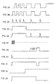
- FIGURE 3 is useful in describing the operation of a servo command circuit in the control circuit shown in FIGURE 2;
- FIGURE 4 is useful in describing the operation of a rotation direction detecting circuit in a position detecting circuit of the control circuit shown in FIGURE 2;
- FIGURE 5 is useful in describing the position detecting circuit of the control circuit shown in FIGURE 2; and
- FIGURE 6 is useful in describing a current control circuit of the control circuit shown in FIGURE 2.
-
- According to one embodiment of the present invention, a DC motor control apparatus is used to control a DC motor, e.g. a DC
brushless motor 2, as shown in FIGURE 1. TheDC motor 2 may be used for driving a load, for example, a conveyor or a winch for rolling up an advertising banner. TheDC motor 2 has arotor 4 and a stator 6. Therotor 4 may be of four-poled type. A driving signal is applied to the stator 6 from adriver 8, whereby theDC motor 2 rotates. - The
driver 8 causes theDC motor 2 to rotate in accordance with a rotation command signal, a rotation direction indicating signal and a driving force indicating signal, which are supplied to thedriver 8 from arotation control circuit 10. As far as the rotation command signal is applied to thedriver 8, theDC motor 2 rotates. The direction in which theDC motor 2 rotates is determined by the rotation direction indicating signal. Also, the driving force provided by theDC motor 2 is dependent on the driving force indicating signal. - The
control circuit 10 receives an externally supplied operation/stop signal and an externally supplied forward/reverse signal. When the operation/stop signal is at its first state, e.g. at its high (H) level, theDC motor 2 is caused to rotate, and, when the operation/stop signal is at its second state, e.g. at its low (L) level, theDC motor 2 is stopped. When the forward/reverse signal is at its first state, e.g. at its H level, theDC motor 2 is driven to rotate forward, and when the forward/reverse signal is at its second state, e.g. at its L level, theDC motor 2 is driven to rotate in the reverse direction. - Thus, the
control circuit 10 generates such rotation command and rotation direction indicating signals as to cause thedriver 8 to rotate theDC motor 2 in the forward direction when the operation/stop and forward/reverse signals applied to thecontrol circuit 10 are both at the H level. Thecontrol circuit 10 generates such rotation command and rotation direction indicating signals as to cause thedriver 8 to rotate theDC motor 2 in the reverse direction when the operation/stop signal is at the H level and the forward/reverse signal is at the L level. - The driving force indicating signal is for causing the
DC motor 2 to produce a predetermined constant driving force whichever direction theDC motor 2 is rotated. - In order to detect the rotation of the
rotor 4, a plurality, e.g. three, of rotation speed detectors, e.g. Hall effect devices, 12a, 12b and 12c are disposed around therotor 4 at predetermined angular intervals, e.g. sixty degrees (60°). As a pole of therotor 4 passes each of theHall effect devices 12a, 12b and 12c, a pulse is generated by that Hall effect device. For example, when therotor 4 of theDC motor 2 is rotating in the forward direction, one of its poles passes theHall effect devices 12a, 12b and 12c in the named order. This makes theHall effect devices 12a, 12b and 12c successively generate a pulse in the named order. When therotor 4 rotates in the reverse direction and, therefore, the same pole passes theHall effect devices 12c, 12b and 12a in the named order, pulses are generated successively by theHall effect devices 12c, 12b and 12a in the named order. Pulse signals from theHall effect devices 12a, 12b and 12c are supplied to thecontrol circuit 10 for use in braking theDC motor 2 when the operation/stop signal changes its level to the L level. The pulses generated by the Hall effect device 12a are phase shifted by 60 degrees from the pulses from theHall effect device 12b, and the pulses from theHall effect device 12b are phase shifted by 60 degrees from the pulses from the Hall effect device 12c. - FIGURE 2 is a block circuit diagram showing details of the
control circuit 10. As shown in FIGURE 2, thecontrol circuit 10 is formed of logic circuits. No microcomputer is used. A microcomputer may be used for thecontrol circuit 2, but it is not necessarily required, since theHall effect devices 12a, 12b and 12c have a resolution of 1/12 rotation, for which a microcomputer need not be used, but logic circuits are sufficient to process the signals. On the other hand, if an encoder having a high resolution of, for example, 1/100 rotation is used, a microcomputer is required to provide a fine control. A large number of logic circuits may be required to process signals from such high-resolution encoder. - As described previously, the
control circuit 10 receives the operation/stop signal and the forward/reverse signal from external signal sources, and the pulse signals from theHall effect devices 12a, 12b and 12c, through aconnector 23. The pulse signals from theHall effect devices 12a, 12b and 12c are coupled to thecontrol circuit 10 through terminals IN1, IN3 and IN5, respectively, of theconnector 23. The operation/stop signal and the forward/reverse signal are coupled to thecontrol circuit 10 through terminals RUN and CW of theconnector 23. A terminal CP of theconnector 23 is for providing clock signals to acounter 30, as will be described later. - The
control circuit 10 includes aservo command circuit 14, a position detecting circuit 16, and acurrent control circuit 18. - The
servo command circuit 14 produces a rotation command signal, e.g. a servo command signal, for braking theDC motor 2 when the rotation rate of theDC motor 2 decreases to a predetermined rate, e.g. 300 r.p.m., as a result of the operation/stop signal being placed to the L level and, therefore, the driving of theDC motor 2 being stopped. - The position detecting circuit 16 detects the direction of rotation of the
DC motor 2 when theservo command circuit 14 generates the servo command signal, and generates a rotation direction indicating signal to command theDC motor 2 to rotate in the direction opposite to the detected direction. - The
current control circuit 18 couples this rotation direction indicating signal to thedriver 8 when it receives the servo command signal. After receiving the servo command signal, thecurrent control circuit 18 generates a first driving force indicating signal so as to drive theDC motor 2 to rotate in the above-stated opposite direction with a first driving force when theDC motor 2 is rotating at a rate within a first predetermined range of rotation rates. Thecurrent control circuit 18 provides a second driving force indicating signal so as to drive the DC motor to rotate with a second driving force larger than the first driving force when theDC motor 2 is rotating at a rotation rate within a second range of rotation rates above the first range in spite of the first driving force indicating signal provided by thecurrent control circuit 18. - More specifically, when the rotation rate of the
DC motor 2 decreases below a predetermined rotation rate after the operation/stop signal changes to the L level to thereby command theDC motor 2 to stop, the servo command signal is generated. In response to it, the actual direction of rotation of theDC motor 2 is detected, and theDC motor 2 is driven to rotate in the opposite direction. The magnitude of the current to be supplied to theDC motor 2 at this instant is indicated by the first driving force indicating signal, according to which theDC motor 2 is braked. If theDC motor 2 continues to rotate in spite of the braking, a current having a magnitude designated by the second driving force indicating signal is applied to theDC motor 2 to thereby apply a larger braking force causing theDC motor 2 to stop. - After the
DC motor 2 stops rotating, a current determined in accordance with the first or second driving force indicating signal is continuously applied to the DC motor to maintain the braking force. - Next, the operation of the
control circuit 10 when the forward/reverse signal at the terminal CW of theconnector 23 is at the H level (indicating that theDC motor 2 should rotate in the forward direction) with the operation/stop signal at the terminal RUN of theconnector 23 being at the H level (indicating that theDC motor 2 should be rotated) is described. The forward/reverse signal at the H level is applied to one input of an ANDgate 20 of the position detecting circuit 16, and the operation/stop signal at the H level is applied to the other input of the ANDgate 20. Accordingly, the output of the ANDgate 20 is at the H level. The H level output is coupled through anOR gate 22 to a rotation direction indicating terminal (CW) of aconnector 24 for connection to thedriver 8. This causes thedriver 8 to drive themotor 2 to rotate in the forward direction. The H level operation/stop signal is coupled through ORgates current control circuit 18 to a rotation command terminal (RUN) of theconnector 24 so that thedriver 8 drives theDC motor 2 to rotate. When the forward/reverse signal is at the L level, the CW terminal of theconnector 24 is at the L level, and thedriver 8 drives themotor 2 to rotates in the reverse direction. When the operation/stop signal is at the L level, the RUN terminal is also at the L level, and, therefore, thedriver 8 does not supply a driving signal to themotor 2. - The
servo command circuit 14 has acounter 30 having a clock terminal CLK to which a clock signal at, for example, 3.2 KHz is applied from the CP terminal of theconnector 23. Thecounter 30 has also a reset terminal RST to which an output signal of an OR gate 32 is applied. The OR gate 32 receives the operation/stop signal at its one input terminal. Accordingly, when the operation/stop signal is at its H level, thecounter 30 is reset. The other input terminal of the OR gate 32 receives the pulse signal from the Hall effect device 12a inverted in aninverter 34 and differentiated in a differentiating circuit 36. - FIGURE 3A shows the pulse signal from the Hall effect device 12a, FIGURE 3B shows the output signal of the
inverter 34, and FIGURE 3C shows the output signal of the differentiating circuit 36. FIGURE 3D shows the forward/reverse signal, FIGURE 3E shows the output signal of the OR gate 32, and FIGURE 3F shows the clock signal. - When receiving the reset signal, the
counter 30 is reset to its initial count, e.g. zero (0), and starts counting the clock signal. During operation of themotor 2, the differentiated signal of the differentiating circuit 36 occurs at predetermined intervals, and, therefore, thecounter 30 is reset before it counts a predetermined count, e.g. the count value at which its output terminal Q10 assumes the H level. Accordingly, as is seen from the left portion of the waveform shown in FIGURE 3G, which shows the output at the Q10 terminal of thecounter 30, the Q10 terminal of thecounter 30 is at the L level. When the operation/stop signal changes its level to the L level and, therefore, no driving power is supplied to themotor 2, the interval between adjacent pulses of the pulse signal of the Hall effect device 12a increases as shown in the latter half portion of the waveform of FIGURE 3A, resulting in increase of the interval between adjacent pulses of the reset signal. As a result, the Q10 output terminal of thecounter 30 becomes high (H) before thecounter 30 is reset. In this manner, the decrease of the rotation rate of themotor 2 to a rate below a predetermined rate is detected. The H level signal at the Q10 output terminal of thecounter 30 is applied to one input terminal of a NORgate 38, which receives at the other input terminal a differentiated signal, shown in FIGURE 3H, resulting from differentiating a supply voltage in an differentiatingcircuit 40. Accordingly, the output signal of the NORgate 38 assumes the L level when the power supply is connected, and when the rotation rate of themotor 2 decreases below the predetermined rotation rate, as shown in FIGURE 3l. - The output signal of the NOR
circuit 38 is coupled to an R1 terminal of an integrated circuit (IC) 42 in which four flip-flop circuits are integrated. TheIC 42 receives at its S1 terminal, an inverted version (FIGURE 3J) of the operation/stop signal prepared in aninverter 41. TheIC 42 is arranged to provide a L level output signal at its Q1 terminal when the R1 terminal is at the L level with the S1 terminal assuming the H level. Thus, as shown in FIGURE 3K, when the signal at the Q1 terminal of theIC 42 changes its level from the H level to the L level, and the rotation rate of themotor 2 decreases below the predetermined rate, the servo command signal is developed. - Next, the position detecting circuit 16 is described. The position detecting circuit 16 includes a rotation directing detecting
circuit 44. The rotationdirection detecting circuit 44 includes an ANDgate 46 of which one input receives the output of theinverter 34 via the differentiating circuit 36. The ANDgate 46 receives, at its other input terminal, the pulse signal from theHall effect device 12b. - The rotation
direction detecting circuit 44 includes further aninverter 48 to which the output of theinverter 34 is applied, and a differentiatingcircuit 50 which differentiates the output of theinverter 48. The output, differentiated signal of the differentiatingcircuit 50 is applied to one input of an ANDgate 52, which receives, at the other input terminal, the pulse signal of the Hall effect device 12c. The output signals of the ANDgates gate 54. - FIGURES 4A, 4B and 4C show the pulse signals of the
Hall effect devices 12a, 12b and 12c, respectively, and FIGURE 4D shows the output signal of the differentiatingcircuit 50. Comparing the waveform shown in FIGURE 4A with the one shown in FIGURE 4D, it is seen that each time a pulse of the pulse signal of the Hall effect device 12a rises, a pulse occurs in the output signal of the differentiatingcircuit 50. The left portions of the waveforms shown in FIGURES 4A, 4B and 4C are the waveforms of the pulse signals when themotor 2 is rotating in the forward direction. When themotor 2 is rotating in the forward direction, the output signal of the ANDgate 52, to which the output of the differentiatingcircuit 50 and the pulse signal from the Hall effect device 12c are applies, is as shown in the left portion of the waveform shown in FIGURE 4E, from which it is understood that the output of the ANDgate 52 assumes the H level in synchronization with the rising edge of the pulse signal of the Hall effect device 12a. The output signal of the differentiating circuit 36 is the differentiated version of the pulse signal from the Hall effect device 12a inverted in theinverter 34. Accordingly, as is understood from the waveform shown in FIGURE 4F, the output signal of the differentiating circuit 36 is synchronized with the falling edge of the pulse signal from the Hall effect device 12a. The output signal of the ANDgate 46 to which the output signal of the differentiating circuit 36 and the pulse signal from theHall effect device 12b are applies assumes the H level in synchronization with the falling edge of the pulse signal from the Hall effect device 12a when themotor 2 is rotating in the forward direction., as shown in FIGURE 4G. The output signal of the NORgate 54 to which the output signals of the ANDgates motor 2 is rotating in the forward direction. - The latter halves of the waveforms shown in FIGURES 4A through 4H are waveforms resulting when the
motor 2 is rotating in the reverse direction. - As is shown in the right half portions of FIGURES 4D and 4C, when the output signal of the differentiating
circuit 50 assumes the H level, the pulse signal of the Hall effect device 12c is at the L level, and, as shown in FIGURE 4E, the output of the ANDgate 52 is at the L level. Also, when the output signal of the differentiating circuit 36 is at the H level, the pulse signal of theHall effect device 12b is at the L level, as is understood from the latter half portions of FIGURES 4F and 4B. In this case, the output signal of the ANDgate 46 is at the L level as shown in the latter half portion of FIGURE 4G. Accordingly, the output signal of the NORgate 54 continues to be at the H level as shown in the latter portion of FIGURE 4H. In this way, the output signal of the NORgate 54 alternates between the H level and the L level when themotor 2 is rotating in the forward direction, but it maintains the H level when themotor 2 is rotating in the reverse direction. - The rotation
direction detecting circuit 44 further includes an ANDgate 56, an ANDgate 58 and a NORgate 60. The ANDgate 56 receives the output signal of the differentiating circuit 36 and the pulse signal from the Hall effect device 12c. The ANDgate 58 receives the output signal of the differentiatingcircuit 50 and the pulse signal of theHall effect device 12b. The NORgate 60 receives output signals from the ANDgates gate 60 maintains to be at the H level when themotor 2 is rotating in the forward direction, while it assumes the L level in synchronization with the rising and falling edges of the pulse signal of the Hall effect device 12a when themotor 2 is rotating in the reverse direction, as is understood from the description of the operation of the ANDgates gate 54 given above. - The output signal of the NOR
gate 54 is applied to an S0 terminal of theIC 42, while the output signal of the NORgate 60 is applied to an R0 terminal of theIC 42. The level at a Q0 terminal of theIC 42 depends on the levels of the signals at the S0 and R0 terminals. Assuming, for example, that themotor 2 is rotating in the forward direction, the pulse signal shown in the first half portion of FIGURE 5A is applied to the S0 terminal, while the pulse signal at the H level shown in the first half of FIGURE 5B is applied to the R0 terminal of theIC 42. As a result, the Q0 output of theIC 42 assumes the H level when the output signal of the NORgate 54 first assumes the L level, as shown in the first half portion of FIGURE 5C. The H level signal at the Q0 terminal is applied to an UP/DOWN terminal of acounter 62 so as to place thecounter 62 in the count up condition, as shown in the first half portion of FIGURE 5F. The H level signal at the Q0 terminal of theIC 42 is inverted in aninverter 66 and then applied to an UP/DOWN terminal of acounter 64 so that thecounter 64 can count down. ENABLE terminals (PE) of thecounters IC 42 when the motor speed decreases to a rotation speed below a predetermined value, as shown in the first half of FIGURE 5E, so that they can start counting. Clock (CLK) terminals of thecounters OR gate 68 which receives the output signals of the differentiatingcircuits 36 and 50. As a result, when the rotating rate of themotor 2 rotating in the forward direction decreases below the predetermined value, thecounter 62 starts counting up, as is understood from the first half portions of FIGURES 5G through 5J, which represent waveforms of output signals at Q0, Q1, Q2 and Q3 terminals of thecounter 62, respectively, and the counter 64 starts counting down. - The output signals at the Q1 and Q2 terminals of the
counter 62 are applied to anOR gate 70, and, therefore, theOR gate 70 develops an output which assumes the H level when the counter 62 counts the second clock pulse, as is shown in the first half portions of FIGURE 5K. The H level signal is applied to anOR gate 72 which also receives an output signal at the Q0 terminal of thecounter 62. Then, the output of theOR gate 72 assumes the H level when the first clock pulse is counted, as is shown in the first half portion of FIGURE 5L. This H level signal from theOR gate 72 is applied to a clock (CLK) terminal of a D-type flip-flop 76 via anOR gate 74. The flip-flop 76 receives at its D input terminal the Q0 output of theIC 42, which is at the H level when themotor 2 is rotating in the forward direction, as previously described. Accordingly, the Q andQ terminals of the D-type flip-flop 76 are at the H and L levels, as shown in the first half portions of FIGURES 5M and 5N, respectively, when the rotation rate of themotor 2 rotating the forward direction decreases below the predetermined value. - The L level signal at the
Q terminal of the flip-flop 76 is applied to one input of an ANDgate 78, which also receives at its other input terminal an inverted version of the operation/stop signal through aninverter 41. The output of the AND gate is at the L level, which is applied to the CW terminal of theconnector 24 through theOR gate 22. As a result, thedriver 8 is commanded to rotate themotor 2 in the reverse direction. - Although detailed description is not given, the operation when the speed of the
motor 2 rotating in the reverse direction decreases to a value below the predetermined value, will be understood from the description given heretofore and from the illustration in the latter half portions of the waveforms shown in FIGURES 5A through 5N. When the rotation rate of themotor 2 when it is rotating in the reverse direction decreases the predetermined value, the Q andQ terminals of the D-type flip-flop 76 assume the L and H levels, respectively. The H level at theQ terminal is coupled to the ANDgate 78. At this instant, the output signal of theinverter 41 is at the H level since it is the inverted version of the L level operation/stop signal, and, therefore, the output signal of the ANDgate 78 is at the H level, which is coupled to the CW terminal of theconnector 24 via theOR gate 22. Accordingly, thedriver 8 receives a command to rotate themotor 2 in the forward direction. - Next, the
current control circuit 18 is described. Thecurrent control circuit 18 is for controlling the speed or rotation rate of themotor 2, and includes thecounters OR gate 70. - FIGURE 6A shows the signal at the UP/DOWN terminal of the
counter 62, FIGURE 6B shows the CLOCK signal applied to thecounter 62, and FIGURE 6C is the ENABLE signal at the PE terminal of thecounter 62. FIGURES 6D through 6G show the signals at the Q0, Q1, Q2 and Q3 terminals of thecounter 62, respectively. As in the case of FIGURES 5A through 5N, the first half portions of FIGURES 6A through 6X are waveforms occurring when themotor 2 is rotating in the forward direction, the operation/stop signal has changed to the L level, and the rotation rate of themotor 2 has decreased below the predetermined value. - The output signal of the
OR gate 70 assumes the H level when the second clock pulse occurs and continues to be at the H level until the eighth clock pulse occurs, as shown in the first half portion of FIGURE 6H. This output signal of theOR gate 70 is applied to one input of an ANDgate 80, which also receives, at its other input terminal, the output from the Q terminal of the D-type flip-flop 76. At this time, when themotor 2 is rotating in the forward direction, the operation/stop signal has changed to the L level, and the rotation rate of themotor 2 has decreased below the predetermined value, the output signal at the Q terminal of the D-type flip-flop 76 is at the H level, as shown in the first half portion of FIGURE 6L. Then, the output of the ANDgate 80 is at the H level, as shown in the first half portion of FIGURE 60, which level is coupled to one input of an ANDgate 84 through theOR gate 82. - The other input of the AND
gate 84 receives an inverted version of the output signal of theOR gate 26 from aninverter 86. As previously described, theOR gate 26 receives the operation/stop signal, which is, at this time, is at the L level. The other input of theOR gate 26 receives an output of anOR gate 88, to which an output of an ANDgate 90 is applied. One input of the ANDgate 90 receives the output at the Q3 terminal of thecounter 62, which is at the L level in this instant. Accordingly, the output of the ANDgate 90 is at the L level. An output of an ANDgate 91 is applied to the other input of theOR gate 88. The ANDgate 91 receives at its one input the output at theQ terminal of the D-type flip-flop 76, which, in this instant, is at the L level, as shown in the first half portion of FIGURE 6M, and, therefore, the output of the ANDgate 91 is at the L level. Since the output of theOR gate 88 is at the L level and, therefore, only L level signals are applied to theOR gate 26, the output of theinverter 86 is at the H level. Thus, the output signal (FIGURE 6V) from the ANDgate 84 assumes the H level from the time the second clock pulse occurs to the time immediately before the eighth pulse occurs. - The H level output signal from the AND
gate 84 is applied to the RUN terminal of theconnector 24 through theOR gate 28, which results in a command to be given to thedriver 8 to drive themotor 2. The output signal from theOR gate 28 is shown in FIGURE 6W. - The H level output signal of the AND
gate 84 is also connected to a variable resistance device, e.g. atransistor 100, through a resistor 92, azener diode 94, adiode 96 and an integratingcircuit 98. The H level output signal of the ANDgate 84 is coupled to the base of thetransistor 100 in the illustrated example. Thezener diode 94 is to limit the possible maximum value of the voltage to be applied to the integratingcircuit 98 to a predetermined first value, e.g. 2 V. Accordingly, as is seen in the first half portion of FIGURE 6X, the voltage applied to the base of thetransistor 100 gradually increases toward 2 V, so that the current supplied from aDC source 102 through thetransistor 100 to a SPEED terminal of theconnector 24 gradually increases to a predetermined value, e.g. 1A, and thedriver 8 causes themotor 2 to be braked in accordance with this current. - In this manner, when, for example, the
motor 2 is rotating in the forward direction and the operation/stop signal commands themotor 2 to stop rotating, causing the rotation rate of themotor 2 to decrease to a rate below a predetermined value, themotor 2 is so energized as to rotate in the reverse direction, i.e. braked. If themotor 2 stops rotating within a period between the second clock pulse and the seventh clock pulse, which does not cause the count in thecounter 62 to change, the output signal of the ANDgate 84 is kept at the H level. Therefore, the voltage being applied to the SPEED terminal of theconnector 24 does not change, and, therefore, the braking force exerted at that time is maintained. - If the rotation of the
motor 2 does not stop even if themotor 2 is given reverse rotation energization, the Q0, Q1 and Q2 terminals of thecounter 62 are placed at the L level and the Q3 terminal is placed at the H level, as is seen in the first half portions of FIGURES 6D through 6G. As a result, the output signal of the ANDgate 80 changes to the L level, as shown in the first half portion of FIGURE 60, while the output of the ANDgate 90 changes to the H level, as shown in the first half of FIGURE 6P because the H level output at the Q3 terminal of thecounter 62 and the H level output at the Q terminal of the D-type flip-flop 76 are applied to the ANDgate 90. The H level output of the ANDgate 90 is applied through the ORgates inverter 86, resulting in an L level output signal developed by the ANDgate 84, which, in turn, results in ceasing of the application to thetransistor 100 of the voltage whose possible maximum value is limited to 2 V. - Instead, the H level output of the AND
gate 90 is coupled through the ORgates resistor 104, azener diode 106, adiode 108 and the integratingcircuit 98 to the base of thetransistor 100. Thezener diode 106 is chosen to provide a possible maximum voltage of 5 V to the integratingcircuit 98, so that a voltage increasing toward 5 V, as shown in the first half portion of FIGURE 6X, is applied to the base of thetransistor 100. A current corresponding to the voltage applied to the base of thetransistor 100 is supplied to the SPEED terminal of theconnector 24, and, therefore, thedriver 8 brakes themotor 2 with a possible maximum current of, for example, 1.2 A. In this case, the H level output signal of theOR gate 26 is applied through theOR gate 28 to the RUN terminal of theconnector 24, and, therefore, the application of a command to operate themotor 2 to thedriver 8 continues. - When the rotation rate of the
motor 2 rotating in the reverse direction decreases below a predetermined rate, the signal at the UP/DOWN (U/D) terminal of thecounter 62 assumes the L level, as shown in the second or right half of FIGURE 6A, so that thecounter 62 is placed in the count-down mode of operation. At the same time, thecounter 64 is placed in the count-up mode of operation to thereby start count-up operation in response to the clock signal, as shown in the second half portions of FIGURES 61, 6J and 6K. The outputs at the Q1 and Q2 terminals of thecounter 64 are coupled to the inputs of anOR gate 110, and, therefore, theOR gate 110 develops an H level output signal after the servo command signal occurs. The H level output signal of theOR gate 110 occurs upon the second clock pulse and continues until the eighth clock pulse, as shown in the second half portion of FIGURE 6N, and is applied to an ANDgate 112. The ANDgate 112 receives the output signal developed at theQ terminal of the D-type flip-flop 76, too. The output signal at theQ terminal is at the H level since themotor 2 is rotating in the reverse direction. Accordingly, the output signal of the AND gate 112 (FIGURE 6Q) is at the H level, which is coupled to the ANDgate 84 through theOR gate 82. At this time, the output signal of theinverter 86 is at the H level. Specifically, theinverter 86 is supplied with the output signal of theOR gate 26, which, in turn, is supplied with the operation/stop signal (FIGURE 6T) which is at the L level. TheOR gate 26 receives also the output signal of theOR gate 88 which, in turn, is supplied with the output signal of the ANDgate 90 and the output signal of the AND gate 91 (FIGURE 6R). The output signal of the ANDgate 90 is at the L level since the L level output signal of the D-type flip-flop 76 is applied to it, and the output signal of the ANDgate 91 is also at the L level since the signal at the Q3 terminal of thecounter 64, which is applied to the ANDgate 91, is at the L level. Accordingly, the output signal of the OR gate 88 (FIGURE 6S) is also at the L level, the output of the OR gate 26 (FIGURE 6U) is also at the L level. The output signal of the ANDgate 84 is at the H level. The H level output signal of the ANDgate 84 is applied through the resistor 92, thezener diode 94, thediode 96 and the integratingcircuit 98 to the base of thetransistor 100, whereby themotor 2 is controlled in a manner similar to the one described above with reference to the rotation of themotor 2 in the forward direction. The H level output signal of the ANDgate 84 is coupled through theOR gate 28 to the RUN terminal of theconnector 24, which is then coupled as the rotation command signal to thedriver 8. - Upon the occurrence of the eighth clock pulse, the level of the output signal of the
OR gate 70 changes to the L level, so that the level of the output signal of the ANDgate 84 changes to the L level, too. At the same time, the signal at the Q3 terminal of thecounter 64 assumes the H level, which is coupled to the ANDgate 91. The ANDgate 91 receives also the H level signal from the Q terminal of the D-type flip-flop 76, and, therefore, its output signal is at the H level. The output signal at the H level from the ANDgate 91 is coupled through the ORgates resistor 104, thezener diode 106, thediode 108 and the integratingcircuit 98 to thetransistor 100. The H level signal at the output of theOR gate 26 is coupled to the RUN terminal of theconnector 24 through theOR gate 28, so that the rotation command signal remains at the H level. Like this, when the rotation rate of themotor 2 rotating in the reverse direction decreases below a predetermined rate, themotor 2 is energized to rotate in the forward direction, being controlled in a manner similar to the one described above with reference to themotor 2 rotating in the forward direction at a rotation rate lower than the predetermined rate. - In place of the Hall effect devices used in the above-described embodiment, other rotation detecting means, such as an encoder, may be used. Also, the
control circuit 10 may be realized by a microcomputer rather than logic circuits. Further, thebipolar transistor 100 may be replaced by a FET. Also, OR gates may be used in place of thediodes - The above-described embodiment is so arranged that if the rotation rate of the
motor 2 cannot decrease sufficiently by one braking action, the braking force given to themotor 2 is increased. However, a single braking action may be sufficient in some case, and more than two braking actions may be required in some other cases.
Claims (5)
- A DC motor control apparatus comprising:a rotation detector generating a pulse signal each time a DC motor rotates a predetermined angle;a servo command circuit providing a servo command signal when the rotation rate of said DC motor is judged, based on said pulse signal, to have decreased below a predetermined rate in response to a stop command given to said motor;a rotation direction indicating circuit providing, when said servo command signal is generated, a rotation direction indicating signal based on said pulse signal to indicate that said motor should be rotated in an opposite direction;a braking force indicating circuit generating and holding a braking force indicating signal based on an actual rotation rate at which said motor rotates after said servo command signal is generated; anda driver causing said motor to rotate in the direction indicated by said rotation direction indicating signal, while applying to said motor a braking force based on said braking force indicating signal.
- The DC motor control apparatus according to Claim 1 wherein said servo command circuit comprises:a counter for counting a clock signal from a predetermined count each time said pulse signal is applied to said counter; anda servo signal generator for generating said servo command signal when said counter counts a predetermined count.
- The DC motor control apparatus according to Claim 1 wherein:said rotation detector comprises a first rotation detecting circuit for generating a first pulse signal as said pulse signal, and a second rotation detecting circuit for generating a second pulse signal as said pulse signal, said first and second rotation detecting circuits being arranged such that when said motor is rotating in a forward direction, said first pulse signal precedes said second pulse signal, and when said motor is rotating in a reverse direction, said second pulse signal precedes said first pulse signal; andsaid rotation direction indicating circuit receives said first and second pulse signals, said rotation direction indicating circuit generating a reverse rotation indicating signal as said rotation direction indicating signal when said first pulse signal precedes said second pulse signal, and generating a forward rotation indicating signal as said rotation direction indicating signal when said second pulse signal precedes said first pulse signal.
- The DC motor control apparatus according to Claim 1 wherein said braking force indicating circuit counts a clock signal prepared based on said pulse signal, and commands said driver to rotate said motor with a predetermined first braking force being applied to said motor when a count counted is within a predetermined first range, said braking force indicating circuit commanding said driver to rotate said motor with a predetermined second braking force, greater than said first braking force, being applied to said motor when said count is within a second range above said first range.
- The DC motor control apparatus according to Claim 1 wherein said rotation detecting circuit comprises a Hall effect device, and said servo command circuit, said rotation direction indicating circuit, and said braking force indicating circuit are realized by logic circuits.
Applications Claiming Priority (2)
| Application Number | Priority Date | Filing Date | Title |
|---|---|---|---|
| JP2001018635A JP2002223584A (en) | 2001-01-26 | 2001-01-26 | Controller for dc motor |
| JP2001018635 | 2001-01-26 |
Publications (2)
| Publication Number | Publication Date |
|---|---|
| EP1227572A2 true EP1227572A2 (en) | 2002-07-31 |
| EP1227572A3 EP1227572A3 (en) | 2003-09-24 |
Family
ID=18884628
Family Applications (1)
| Application Number | Title | Priority Date | Filing Date |
|---|---|---|---|
| EP02250522A Withdrawn EP1227572A3 (en) | 2001-01-26 | 2002-01-25 | DC motor control apparatus |
Country Status (3)
| Country | Link |
|---|---|
| US (1) | US6577092B2 (en) |
| EP (1) | EP1227572A3 (en) |
| JP (1) | JP2002223584A (en) |
Families Citing this family (4)
| Publication number | Priority date | Publication date | Assignee | Title |
|---|---|---|---|---|
| EP1271761B1 (en) * | 2001-06-20 | 2007-07-18 | Nissan Motor Co., Ltd. | Motor controller and control method thereof |
| US7021456B2 (en) * | 2003-12-05 | 2006-04-04 | Rapistan Systems Advertising Corp. | Conveyor roller with brake |
| WO2012161687A1 (en) * | 2011-05-23 | 2012-11-29 | Utc Fire & Security Corporation | System for boiler control |
| JP7152875B2 (en) * | 2018-05-16 | 2022-10-13 | キヤノン株式会社 | Motor control device and image forming device |
Citations (4)
| Publication number | Priority date | Publication date | Assignee | Title |
|---|---|---|---|---|
| US4494052A (en) * | 1982-08-05 | 1985-01-15 | Rca Corporation | DC Motor servo system |
| US4520300A (en) * | 1982-12-06 | 1985-05-28 | Fradella Richard B | Brushless ultra-efficient regenerative servomechanism |
| US5220257A (en) * | 1991-07-15 | 1993-06-15 | Rohm Co., Ltd. | Motor torque control circuit with barking control and motor drive system using the same |
| US5734241A (en) * | 1993-03-19 | 1998-03-31 | Nidec Corporation | Brake control system of a motor |
Family Cites Families (8)
| Publication number | Priority date | Publication date | Assignee | Title |
|---|---|---|---|---|
| US4429262A (en) * | 1980-09-12 | 1984-01-31 | Technicare Corporation | Three phase motor oscillatory servo control |
| US5602449A (en) | 1992-04-13 | 1997-02-11 | Smith & Nephew Endoscopy, Inc. | Motor controlled surgical system and method having positional control |
| US5320421A (en) * | 1992-08-10 | 1994-06-14 | General Motors Corporation | Motor driven brake pressure modulator with motor position control |
| JPH0670851A (en) | 1992-08-28 | 1994-03-15 | Toshiba Electric Appliance Co Ltd | Raw material exchanging device for beverage supply device |
| JPH08191591A (en) | 1995-01-10 | 1996-07-23 | Toshiba Corp | Device for controlling drive of brushless motor |
| JPH11346497A (en) | 1998-06-02 | 1999-12-14 | Fujii Seimitsu Kaitenki Seisakusho:Kk | Dc brushless motor and control method therefor |
| JP2000274464A (en) * | 1998-08-21 | 2000-10-03 | Toyota Motor Corp | Motor-driven brake device |
| US6215261B1 (en) | 1999-05-21 | 2001-04-10 | General Electric Company | Application specific integrated circuit for controlling power devices for commutating a motor based on the back emf of motor |
-
2001
- 2001-01-26 JP JP2001018635A patent/JP2002223584A/en active Pending
-
2002
- 2002-01-22 US US10/054,473 patent/US6577092B2/en not_active Expired - Lifetime
- 2002-01-25 EP EP02250522A patent/EP1227572A3/en not_active Withdrawn
Patent Citations (4)
| Publication number | Priority date | Publication date | Assignee | Title |
|---|---|---|---|---|
| US4494052A (en) * | 1982-08-05 | 1985-01-15 | Rca Corporation | DC Motor servo system |
| US4520300A (en) * | 1982-12-06 | 1985-05-28 | Fradella Richard B | Brushless ultra-efficient regenerative servomechanism |
| US5220257A (en) * | 1991-07-15 | 1993-06-15 | Rohm Co., Ltd. | Motor torque control circuit with barking control and motor drive system using the same |
| US5734241A (en) * | 1993-03-19 | 1998-03-31 | Nidec Corporation | Brake control system of a motor |
Also Published As
| Publication number | Publication date |
|---|---|
| US20020101212A1 (en) | 2002-08-01 |
| US6577092B2 (en) | 2003-06-10 |
| JP2002223584A (en) | 2002-08-09 |
| EP1227572A3 (en) | 2003-09-24 |
Similar Documents
| Publication | Publication Date | Title |
|---|---|---|
| EP0735664B1 (en) | Angle control system for a switched reluctance drive utilizing a high frequency clock | |
| EP0414703B1 (en) | Starting a brushless dc motor | |
| JP3432226B2 (en) | Pulse width modulation motor controller | |
| US5068582A (en) | Brushless pulsed D.C. motor | |
| US5801509A (en) | Method of starting a permanent-magnet synchronous motor equipped with angular position detector and apparatus for controlling such motor | |
| EP1468486B1 (en) | Method and apparatus for detecting a stall condition in a stepping motor | |
| US5905348A (en) | Powering and control of a brushless DC motor | |
| US6577092B2 (en) | DC motor control apparatus | |
| US5442267A (en) | Device for controlling the reverse rotation of a motor and method of judging time point where the motor is actually rotated in a reverse direction | |
| US6429614B1 (en) | Method and device for controlling an electronically commutated polyphase D.C. motor | |
| US5941359A (en) | Positioning apparatus | |
| JP2000166297A (en) | Drive device and drive mechanism of stepping motor | |
| JP2502680B2 (en) | Brushless motor drive | |
| JPH11299276A (en) | Method for controlling stoppage of electric motor | |
| KR20010068827A (en) | Apparatus and method for driving control of single phase switched reluctance motor | |
| JPH06335273A (en) | Ac motor control apparatus | |
| JPS6359796A (en) | Origin return mechanism for pulse motor | |
| JP2704427B2 (en) | Speed controller for DC brushless motor | |
| KR0136976B1 (en) | A control apparatus and method of brushless motor | |
| JP3126372B2 (en) | Motor control circuit | |
| JP2834288B2 (en) | Motor stop device | |
| KR19980073986A (en) | Drive control unit of switched reluctance motor | |
| JP2820724B2 (en) | Drive control device for servo motor of image reading device | |
| JP2704424B2 (en) | Speed control method of DC brushless motor | |
| JPH0993970A (en) | Simple positioning device for dc motor |
Legal Events
| Date | Code | Title | Description |
|---|---|---|---|
| PUAI | Public reference made under article 153(3) epc to a published international application that has entered the european phase |
Free format text: ORIGINAL CODE: 0009012 |
|
| AK | Designated contracting states |
Kind code of ref document: A2 Designated state(s): AT BE CH CY DE DK ES FI FR GB GR IE IT LI LU MC NL PT SE TR |
|
| AX | Request for extension of the european patent |
Free format text: AL;LT;LV;MK;RO;SI |
|
| PUAL | Search report despatched |
Free format text: ORIGINAL CODE: 0009013 |
|
| AK | Designated contracting states |
Kind code of ref document: A3 Designated state(s): AT BE CH CY DE DK ES FI FR GB GR IE IT LI LU MC NL PT SE TR |
|
| AX | Request for extension of the european patent |
Extension state: AL LT LV MK RO SI |
|
| 17P | Request for examination filed |
Effective date: 20030923 |
|
| AKX | Designation fees paid |
Designated state(s): DE FR GB |
|
| 17Q | First examination report despatched |
Effective date: 20070122 |
|
| STAA | Information on the status of an ep patent application or granted ep patent |
Free format text: STATUS: THE APPLICATION IS DEEMED TO BE WITHDRAWN |
|
| 18D | Application deemed to be withdrawn |
Effective date: 20090801 |