EP1223902B1 - Liquefracture handpiece - Google Patents
Liquefracture handpiece Download PDFInfo
- Publication number
- EP1223902B1 EP1223902B1 EP00961835A EP00961835A EP1223902B1 EP 1223902 B1 EP1223902 B1 EP 1223902B1 EP 00961835 A EP00961835 A EP 00961835A EP 00961835 A EP00961835 A EP 00961835A EP 1223902 B1 EP1223902 B1 EP 1223902B1
- Authority
- EP
- European Patent Office
- Prior art keywords
- handpiece
- tube
- tip
- fluid
- pumping chamber
- Prior art date
- Legal status (The legal status is an assumption and is not a legal conclusion. Google has not performed a legal analysis and makes no representation as to the accuracy of the status listed.)
- Expired - Lifetime
Links
Images


Classifications
-
- A—HUMAN NECESSITIES
- A61—MEDICAL OR VETERINARY SCIENCE; HYGIENE
- A61F—FILTERS IMPLANTABLE INTO BLOOD VESSELS; PROSTHESES; DEVICES PROVIDING PATENCY TO, OR PREVENTING COLLAPSING OF, TUBULAR STRUCTURES OF THE BODY, e.g. STENTS; ORTHOPAEDIC, NURSING OR CONTRACEPTIVE DEVICES; FOMENTATION; TREATMENT OR PROTECTION OF EYES OR EARS; BANDAGES, DRESSINGS OR ABSORBENT PADS; FIRST-AID KITS
- A61F9/00—Methods or devices for treatment of the eyes; Devices for putting-in contact lenses; Devices to correct squinting; Apparatus to guide the blind; Protective devices for the eyes, carried on the body or in the hand
- A61F9/007—Methods or devices for eye surgery
- A61F9/00736—Instruments for removal of intra-ocular material or intra-ocular injection, e.g. cataract instruments
-
- A—HUMAN NECESSITIES
- A61—MEDICAL OR VETERINARY SCIENCE; HYGIENE
- A61B—DIAGNOSIS; SURGERY; IDENTIFICATION
- A61B17/00—Surgical instruments, devices or methods, e.g. tourniquets
- A61B17/32—Surgical cutting instruments
- A61B17/3203—Fluid jet cutting instruments
-
- A—HUMAN NECESSITIES
- A61—MEDICAL OR VETERINARY SCIENCE; HYGIENE
- A61B—DIAGNOSIS; SURGERY; IDENTIFICATION
- A61B17/00—Surgical instruments, devices or methods, e.g. tourniquets
- A61B17/32—Surgical cutting instruments
- A61B17/320068—Surgical cutting instruments using mechanical vibrations, e.g. ultrasonic
- A61B2017/320084—Irrigation sleeves
-
- A—HUMAN NECESSITIES
- A61—MEDICAL OR VETERINARY SCIENCE; HYGIENE
- A61B—DIAGNOSIS; SURGERY; IDENTIFICATION
- A61B18/00—Surgical instruments, devices or methods for transferring non-mechanical forms of energy to or from the body
- A61B18/04—Surgical instruments, devices or methods for transferring non-mechanical forms of energy to or from the body by heating
- A61B2018/044—Surgical instruments, devices or methods for transferring non-mechanical forms of energy to or from the body by heating the surgical action being effected by a circulating hot fluid
- A61B2018/046—Surgical instruments, devices or methods for transferring non-mechanical forms of energy to or from the body by heating the surgical action being effected by a circulating hot fluid in liquid form
-
- A—HUMAN NECESSITIES
- A61—MEDICAL OR VETERINARY SCIENCE; HYGIENE
- A61F—FILTERS IMPLANTABLE INTO BLOOD VESSELS; PROSTHESES; DEVICES PROVIDING PATENCY TO, OR PREVENTING COLLAPSING OF, TUBULAR STRUCTURES OF THE BODY, e.g. STENTS; ORTHOPAEDIC, NURSING OR CONTRACEPTIVE DEVICES; FOMENTATION; TREATMENT OR PROTECTION OF EYES OR EARS; BANDAGES, DRESSINGS OR ABSORBENT PADS; FIRST-AID KITS
- A61F9/00—Methods or devices for treatment of the eyes; Devices for putting-in contact lenses; Devices to correct squinting; Apparatus to guide the blind; Protective devices for the eyes, carried on the body or in the hand
- A61F9/007—Methods or devices for eye surgery
- A61F9/00736—Instruments for removal of intra-ocular material or intra-ocular injection, e.g. cataract instruments
- A61F9/00745—Instruments for removal of intra-ocular material or intra-ocular injection, e.g. cataract instruments using mechanical vibrations, e.g. ultrasonic
-
- A—HUMAN NECESSITIES
- A61—MEDICAL OR VETERINARY SCIENCE; HYGIENE
- A61F—FILTERS IMPLANTABLE INTO BLOOD VESSELS; PROSTHESES; DEVICES PROVIDING PATENCY TO, OR PREVENTING COLLAPSING OF, TUBULAR STRUCTURES OF THE BODY, e.g. STENTS; ORTHOPAEDIC, NURSING OR CONTRACEPTIVE DEVICES; FOMENTATION; TREATMENT OR PROTECTION OF EYES OR EARS; BANDAGES, DRESSINGS OR ABSORBENT PADS; FIRST-AID KITS
- A61F9/00—Methods or devices for treatment of the eyes; Devices for putting-in contact lenses; Devices to correct squinting; Apparatus to guide the blind; Protective devices for the eyes, carried on the body or in the hand
- A61F9/007—Methods or devices for eye surgery
- A61F9/00736—Instruments for removal of intra-ocular material or intra-ocular injection, e.g. cataract instruments
- A61F9/00763—Instruments for removal of intra-ocular material or intra-ocular injection, e.g. cataract instruments with rotating or reciprocating cutting elements, e.g. concentric cutting needles
-
- A—HUMAN NECESSITIES
- A61—MEDICAL OR VETERINARY SCIENCE; HYGIENE
- A61M—DEVICES FOR INTRODUCING MEDIA INTO, OR ONTO, THE BODY; DEVICES FOR TRANSDUCING BODY MEDIA OR FOR TAKING MEDIA FROM THE BODY; DEVICES FOR PRODUCING OR ENDING SLEEP OR STUPOR
- A61M1/00—Suction or pumping devices for medical purposes; Devices for carrying-off, for treatment of, or for carrying-over, body-liquids; Drainage systems
- A61M1/71—Suction drainage systems
- A61M1/77—Suction-irrigation systems
Definitions
- This invention relates generally to the field of cataract surgery and more particularly to a handpiece for practicing the liquefracture technique of cataract removal.
- the human eye in its simplest terms functions to provide vision by transmitting light through a clear outer portion called the cornea, and focusing the image by way of the lens onto the retina.
- the quality of the focused image depends on many factors including the size and shape of the eye, and the transparency of the cornea and lens.
- IOL intraocular lens
- phacoemulsification In the United States, the majority of cataractous lenses are removed by a surgical technique called phacoemulsification. During this procedure, a thin phacoemulsification cutting tip is inserted into the diseased lens and vibrated ultrasonically. The vibrating cutting tip liquifies or emulsifies the lens so that the lens may be aspirated out of the eye. The diseased lens, once removed, is replaced by an artificial lens.
- a typical ultrasonic surgical device suitable for ophthalmic procedures consists of an ultrasonically driven handpiece, an attached cutting tip, and irrigating sleeve and an electronic control console.
- the handpiece assembly is attached to the control console by an electric cable and flexible tubes. Through the electric cable, the console varies the power level transmitted by the handpiece to the attached cutting tip and the flexible tubes supply irrigation fluid to and draw aspiration fluid from the eye through the handpiece assembly.
- the operative part of the handpiece is a centrally located, hollow resonating bar or horn directly attached to a set of piezoelectric crystals.
- the crystals supply the required ultrasonic vibration needed to drive both the horn and the attached cutting tip during phacoemulsification and are controlled by the console.
- the crystal/horn assembly is suspended within the hollow body or shell of the handpiece by flexible mountings.
- the handpiece body terminates in a reduced diameter portion or nosecone at the body's distal end.
- the nosecone is externally threaded to accept the irrigation sleeve.
- the horn bore is internally threaded at its distal end to receive the external threads of the cutting tip.
- the irrigation sleeve also has an internally threaded bore that is screwed onto the external threads of the nosecone.
- the cutting tip is adjusted so that the tip projects only a predetermined amount past the open end of the irrigating sleeve.
- Ultrasonic handpieces and cutting tips are more fully described in U.S. Pat. Nos. 3,589,363; 4,223,676; 4,246,902; 4,493,694; 4,515,583; 4,589,415; 4,609,368; 4,869,715; 4,922,902; 4,989,583; 5,154,694 and 5,359,996.
- the ends of the cutting tip and irrigating sleeve are inserted into a small incision of predetermined width in the comea, sclera, or other location.
- the cutting tip is ultrasonically vibrated along its longitudinal axis within the irrigating sleeve by the crystal-driven ultrasonic horn, thereby emulsifying the selected tissue in situ.
- the hollow bore of the cutting tip communicates with the bore in the horn that in turn communicates with the aspiration line from the handpiece to the console.
- a reduced pressure or vacuum source in the console draws or aspirates the emulsified tissue from the eye through the open end of the cutting tip, the cutting tip and horn bores and the aspiration line and into a collection device.
- the aspiration of emulsified tissue is aided by a saline flushing solution or irrigant that is injected into the surgical site through the small annular gap between the inside surface of the irrigating sleeve and the cutting tip.
- U.S. Patent No. 5,885,243 discloses a handpiece having a separate pumping mechanism and resistive heating element. Such a structure adds unnecessary complexity to the handpiece.
- GB-A-1445488 discloses a surgical handpiece with a fine pulsating high velocity liquid jet having a pulse frequency of between 0.25 and 333 pulses per second, a pressure above atmospheric of between 15 to about 3500 p.s.i. (103 to about 24132 kN/m 2 ) and having a velocity of between 50 and 500 ft. per second (15.24 and 152.40 m./sec.).
- a nozzle tip comprising a pair of coaxial inner and outer tubes defining an annular injection conduit is described, terminating in a closed distal end defining fine injection ports, which may be directed inwardly to converge on the jet-subjected tissue that is sucked into the inner tube.
- US-A-5,112,339 describes a wedge shaped irrigation/aspiration probe for removal of cataractous tissue from the eye.
- the wedge shape of the tip efficiently lifts cortical material off the posterior capsule and is useful during posterior capsule clean-up.
- Embodiments are described in which the distal portion of the probe includes a bend disposed at an angle of between 0° and 180° with respect to the longitudinal portion.
- a slidable spatula-like element may also extend along the distal end of the probe.
- the present invention improves upon the prior art by providing a surgical handpiece in accordance with claims which follow, having two coaxially mounted tubes or channels mounted to a body.
- the first tube is used for aspiration and is smaller in diameter than the second tube so as to create an annular passage between the first and second tube.
- the annular gap communicates with a pumping chamber formed between two electrodes.
- the pumping chamber works by boiling a small volume of the surgical fluid. As the fluid boils, it expands rapidly, thereby propelling the liquid downstream of the pumping chamber out of the annular gap.
- the distal end of the annular gap is sealed by sealing together the distal ends of the first and second tube and a plurality or orifices or ports may be formed near the seal. As the expanding gas is propelled down the annular gap, the gas/liquid stream is forced out of the distal ports in a controlled and directed manner.
- the distal end of the first and second tubes may contain a bend.
- one objective of the present invention is to provide a surgical handpiece having at least two coaxial tubes.
- Another objective of the present invention is to provide a handpiece having a pumping chamber.
- Another objective of the present invention is to provide a surgical handpiece having a device for delivering the surgical fluid through the handpiece in pulses.
- Still another objective of the present invention is to provide a handpiece having a pumping chamber formed by two electrodes.
- Yet another objective of the present invention is to provide a handpiece having two electrodes wherein the electrodes are insulated.
- Still another objective of the present invention is to provide a handpiece that delivers fluid pulses in a controlled and directed manner.
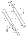
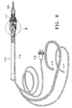
- Handpiece 10 generally includes handpiece body 12 and operative tip 16.
- Body 12 generally includes external irrigation tube 18 and aspiration fitting 20.
- Body 12 is similar in construction to well-known in the art phacoemulsification handpieces and may be made from plastic, titanium or stainless steel.
- operative tip 16 includes tip/cap sleeve 26, needle 28 and tube 30.
- Sleeve 26 may be any suitable commercially available phacoemulsification tip/cap sleeve or sleeve 26 may be incorporated into other tubes as a multi-lumen tube.
- Needle 28 may be any commercially available hollow phacoemulsification cutting tip, such as the TURBOSONICS tip available from Alcon Laboratories, Inc., Fort Worth, Texas.
- Tube 30 may be any suitably sized tube to fit within needle 28, for example 29 gauge hypodermic needle tubing.
- tube 30 is free on the distal end and connected to boiling or pumping chamber 42 on the proximal end.
- Tube 30 and pumping chamber 42 may be sealed fluid tight by any suitable means having a relatively high melting point, such as a silicone gasket, glass frit or silver solder.
- Fitting 44 holds tube 30 within bore 48 of aspiration horn 46. Bore 48 communicates with fitting 20, which is journaled into horn 46 and sealed with O-ring seal 50 to form an aspiration pathway through horn 46 and out fitting 20.
- Horn 46 is held within body 12 by O-ring seal 56 to form irrigation tube 52 which communicates with irrigation tube 18 at port 54.
- pumping chamber 42 contains a relatively large pumping reservoir 43 that is sealed on both ends by electrodes 45 and 47. Electrical power is supplied to electrodes 45 and 47 by insulated wires, not shown.
- surgical fluid e.g. saline irrigating solution
- tube 34 and check valve 53 check valves 53 being well-known in the art.
- Electrical current preferably Radio Frequency Alternating Current or RFAC
- RFAC Radio Frequency Alternating Current
- the expanding gas bubble pushes the surgical fluid in tube 30 downstream of pumping chamber 42 forward. Subsequent pulses of electrical current form sequential gas bubbles that move surgical fluid down tube 30.
- the size and pressure of the fluid pulse obtained by pumping chamber 42 can be varied by varying the length, timing and/or power of the electrical pulse sent to electrodes 45 and 47 and by varying the dimensions of reservoir 43.
- the surgical fluid may be preheated prior to entering pumping chamber 42. Preheating the surgical fluid will decrease the power required by pumping chamber 42 and/or increase the speed at which pressure pulses can be generated.
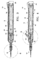
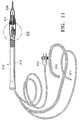
- handpiece 110 which, when modified with a tip curved as in fig. 21 falls within the scope of the present invention, generally includes body 112, having power supply cable 113, irrigation/aspiration lines 115, pumping chamber supply line 117.
- Distal end 111 of handpiece 110 contains pumping chamber 142 having a reservoir 143 formed between electrodes 145 and 147.
- Electrodes 145 and 147 are preferably made from aluminum, titanium, carbon or other similarly conductive materials and are electrically insulated from each other and body 112 by insulating layer 159 such as anodized layer 159 formed on electrodes 145 and 147.
- Anodized layer 159 is less conductive than untreated aluminum and thus, acts as an electrical insulator.
- Electrodes 145 and 147 and electrical terminals 161 and 163 are not anodized and thus, are electrically conductive.
- Layer 159 may be formed by any suitable insulating or anodization technique, well-known in the art, and electrodes 145 and 147 and electrical terminals 161 and 163 may be masked during anodization or machined after anodization to expose bare aluminum. Electrical power is supplied to electrodes 145 and 147 through terminals 161 and 163 and wires 149 and 151, respectively.
- Fluid is supplied to reservoir 143 through supply line 117 and check valve 153. Extending distally from pumping chamber 142 is outer tube 165 that coaxially surrounds aspiration or inner tube 167.
- Tubes 165 and 167 may be of similar construction as tube 30.
- Tube 167 is of slightly smaller diameter than tube 165, thereby forming an annular passage or gap 169 between tube 165 and tube 167.
- Annular gap 169 fluidly communicates with reservoir 143.
- surgical fluid enters reservoir 143 through supply line 117 and check valve 153. Electrical current is delivered to and across electrodes 145 and 147 because of the conductive nature of the surgical fluid. As the current flows through the surgical fluid, the surgical fluid boils. As the surgical fluid boils, it expands rapidly out of pumping chamber 142 through annular gap 169. The expanding gas bubble pushes forward the surgical fluid in annular gap 169 downstream of pumping chamber 142. Subsequent pulses of electrical current form sequential gas bubbles that move or propel the surgical fluid down annular gap 169.
- FIGS. 8-10 is identical to the numbering in FIGS. 1-7 except for the addition of "100" in FIGS. 8-10.
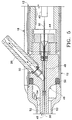
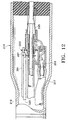
- handpiece 210 which, when modified with a tip curved as in fig. 21 falls within the scope of the present invention, generally includes body 212, having power supply cable 213, irrigation/aspiration lines 215, pumping chamber supply line 217.
- Distal end 211 of handpiece 210 contains pumping chamber 242 having a reservoir 243 formed between electrodes 245 and 247.
- Electrodes 245 and 247 are preferably made from aluminum and electrically insulated from each other and body 212 by anodized layer 259 formed on electrodes 245 and 247.
- Anodized layer 259 is less conductive than untreated aluminum and thus, acts as an electrical insulator.
- Electrodes 245 and 247 and electrical terminals 261 and 263 are not anodized and thus, are electrically conductive.
- Layer 259 may be formed by any suitable anodization technique, well-known in the art, and electrodes 245 and 247 and electrical terminals 261 and 263 may be masked during anodization or machined after anodization to expose bare aluminum. Electrical power is supplied to electrodes 245 and 247 through terminals 261 and 263 and wires 249 and 251, respectively.
- Fluid is supplied to reservoir 243 though supply line 217 and check valve 253.
- Extending distally from pumping chamber 242 is outer tube 265 that coaxially surrounds aspiration or inner tube 267. Tubes 265 and 267 may be of similar construction as tube 30. Tube 267 is of slightly smaller diameter than tube 265, thereby forming an annular passage or gap 269 between tube 265 and tube 267. Annular gap 269 fluidly communicates with reservoir 243.
- surgical fluid enters reservoir 243 through supply line 217 and check valve 253. Electrical current is delivered to and across electrodes 245 and 247 because of the conductive nature of the surgical fluid. As the current flows through the surgical fluid, the surgical fluid boils. The current flow progresses from the smaller electrode gap section to the larger electrode gap section, i.e., from the region of lowest electrical resistance to the region of higher electrical resistance. The boiling wavefront also progresses from the smaller to the larger end of electrode 247. As the surgical fluid boils, it expands rapidly out of pumping chamber 242 through annular gap 269. The expanding gas bubble pushes forward the surgical fluid in annular gap 269 downstream of pumping chamber 242. Subsequent pulses of electrical current form sequential gas bubbles that move or propel the surgical fluid down annular gap 269.
- FIGS. 11-13 is identical to the numbering in FIGS. 1-7 except for the addition of "200" in FIGS. 11-13.
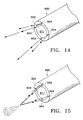
- tip 600 may contain distal end 602 having a plurality of discharge orifices 604.
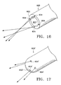
- Orifices 604 may be arranged in a divergent pattern, as illustrated in FIG. 14, a convergent pattern, as illustrated in FIG. 15, or in a non-converging, near miss pattern, as illustrated in FIG. 16, depending upon the targeted tissue and the desired surgical outcome.
- the converging streams create a high pressure region where the streams meet, producing a zone of maximum liquefracture.
- the diverging streams exhibit maximum average pressure directly in front of tip 600, making that the most efficient liquefracture zone in that region.
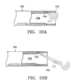
- orifices 604 may be arranged so as to create the designed pattern external to tip 600 or internal to bore 611. Distal end 602 may be formed, for example by crimping the ends of tubes 165 and 167, or 265 and 267, respectively (as illustrated in FIGS. 19 and 20) so that annular gap 169 or 269 is in fluid communication with orifices 604.
- tip 600 may be formed as a separate piece and press fit or otherwise attached to tubes 165 and 167 or 265 and 267 so that tips 600 may be interchangeable. For example, different tip 600 designs may be desired during different portions of a surgical procedure.
- tip 600' may be closed on distal end 602' so that discharge orifices 604' project fluid to the targeted tissue, but tip 600' performs no aspiration function.
- distal end 602" of tip 600 in addition to discharge orifices 604" projecting forward and outward discharge streams 611, may contain orifice or orifices 606 that discharge a fluid stream 610 rearward into aspiration bore 608.
- Stream 610 helps to assure that bore 608 does not become occluded at end 602".
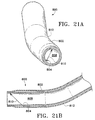
- distal end 802 of tip 800 contains bend 812, bend 812 being at an angle of between 0° and approximately 90° with between 0° and approximately 60° being preferred and between 0° and approximately 20° being most preferred.
- bend 812 is at an angle of between 0° and approximately 90° with between 0° and approximately 60° being preferred and between 0° and approximately 20° being most preferred.
- orifice 804 may be arranged to direct stream 810 internal to bore 808.
- any handpiece producing adequate pressure pulse force, temperature, rise time and frequency may also be used.
- any handpiece producing a pressure pulse force of between 0.02 grams and 20.0 grams, with a rise time of between 1 gram/second and 20,000 grams/second and a frequency of between 1 Hz and 200 Hz may be used, with between 10 Hz and 100 Hz being most preferred.
- the pressure pulse force and frequency will vary with the hardness of the material being removed. For example, the inventors have found that a lower frequency with a higher pulse force is most efficient at debulking and removing the relatively hard nuclear material, with a higher frequency and lower pulse force being useful in removing softer epinuclear and cortical material.
- Infusion pressure, aspiration flow rate and vacuum limit are similar to current phacoemulsification techniques.
- the inventors have determined that the coherence length of the fluid stream is affected by many factors, including the properties of the fluid, ambient conditions, orifice geometry, flow regime at the orifice and pressure of the fluid.
- the coherence length of the fluid pulse stream can be varied.
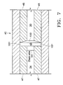
- Tip 700 contains orifice 704 internal to bore 708.
- the coherence length of discharge stream 711 is relatively short, degrading internal to bore 708 around distal end 702. As seen in FIG.
- the coherence length of discharge stream 711 is relatively long, degrading external to bore 708, past distal end 702.
- a pressure stream having a coherence length of approximately between -1.0 millimeters and +5.0 millimeters from distal end 702 is suitable for use in ophthalmic surgery.
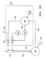
- control system 300 for use in operating handpiece 310 includes control module 347, power gain RF amplifier 312 and function generator 314. Power is supplied to RF amplifier 312 by DC power supply 316, which preferably is an isolated DC power supply operating at several hundred volts, but typically ⁇ 200 volts.
- Control module 347 may be any suitable microprocessor, micro controller, computer or digital logic controller and may receive input from operator input device 318.
- Function generator 314 provides the electric wave form in kilohertz to amplifier 312 and typically operates at around 450 kHz or above to help minimize corrosion.
- control module 347 receives input from surgical console 320.
- Console 320 may be any commercially available surgical control console such as the LEGACY® SERIES TWENTY THOUSAND® surgical system available from Alcon Laboratories, Inc., Fort Worth, Texas.
- Console 320 is connected to handpiece 310 through irrigation line 322 and aspiration line 324, and the flow through lines 322 and 324 is controlled by the user via footswitch 326.
- Irrigation and aspiration flow rate information in handpiece 310 is provided to control module 347 by console 320 via interface 328, which may be connected to the ultrasound handpiece control port on console 320 or to any other output port.
- Control module 347 uses footswitch 326 information provided by console 320 and operator input from input device 318 to generate two control signals 330 and 332.
- Signal 332 is used to operate pinch valve 334, which controls the surgical fluid flowing from fluid source 336 to handpiece 310. Fluid from fluid source 336 is heated in the manner described herein.
- Signal 330 is used to control function generator 314. Based on signal 330, function generator 314 provides a wave form at the operator selected frequency and amplitude determined by the position of footswitch 326 to RF amplifier 312 which is amplified to advance the powered wave form output to handpiece 310 to create heated, pressurized pulses of surgical fluid.
- the pulse train duty cycle of the heated solution can be varied as a function of the pulse frequency so that the total amount of heated solution introduced into the eye does not vary with the pulse frequency.
- the aspiration flow rate can be varied as a function of pulse frequency so that as pulse frequency increases aspiration flow rate increases proportionally.
Abstract
Description
Claims (4)
- A surgical handpiece (110, 210) for lens removed using a pulsed and heated fluid stream comprising:a tip (800) which can be inserted into the eye and .a body (112, 212), said tip and said body comprising an injection channel suitable to discharge a pulsed stream (810) of heated surgical fluid, and an aspiration channel;said injection channel and said aspiration channel being defined by an aspiration tube (167, 267) coaxially mounted within an outer tube (165, 265) so as to form an annular channel (169, 269) between the aspiration tube and the outer tube, said annular channel having a generally closed distal end (802);a pumping chamber (142, 242) mounted within the body, said pumping chamber comprising a reservoir (143, 243) in fluid communication with the annular channel (169, 269) and means for causing surgical fluid in said reservoir to boil;a supply line (217) to supply surgical fluid to the reservoir, said supply line comprising a check valve (153, 253);at least one discharge orifice (804) arranged in said distal end (802) of said annular channel and adapted such that when surgical fluid is caused to be boiled in the pumping chamber, said stream of heated surgical fluid is discharged from said discharge orifice;said tip defining a bend (812) adjacent to said distal end.
- The tip of claim 1, wherein the bend (812) is at an angle of between 0° and approximately 90°.
- The tip of claim 1, wherein the bend (812) is at an angle of between 0° and approximately 60°.
- The tip of claim 1, wherein the bend (812) is at an angle of between 0° and approximately 20°.
Applications Claiming Priority (5)
| Application Number | Priority Date | Filing Date | Title |
|---|---|---|---|
| US525196 | 1983-08-22 | ||
| US429456 | 1999-10-28 | ||
| US09/429,456 US6179805B1 (en) | 1998-06-04 | 1999-10-28 | Liquefracture handpiece |
| US09/525,196 US6589201B1 (en) | 1998-06-04 | 2000-03-14 | Liquefracture handpiece tip |
| PCT/US2000/024982 WO2001030283A1 (en) | 1999-10-28 | 2000-09-12 | Liquefracture handpiece tip |
Publications (2)
| Publication Number | Publication Date |
|---|---|
| EP1223902A1 EP1223902A1 (en) | 2002-07-24 |
| EP1223902B1 true EP1223902B1 (en) | 2004-03-10 |
Family
ID=27028199
Family Applications (1)
| Application Number | Title | Priority Date | Filing Date |
|---|---|---|---|
| EP00961835A Expired - Lifetime EP1223902B1 (en) | 1999-10-28 | 2000-09-12 | Liquefracture handpiece |
Country Status (12)
| Country | Link |
|---|---|
| US (1) | US6589201B1 (en) |
| EP (1) | EP1223902B1 (en) |
| JP (1) | JP2003515363A (en) |
| AT (1) | ATE261287T1 (en) |
| AU (1) | AU767867B2 (en) |
| BR (1) | BR0015139A (en) |
| CA (1) | CA2382475A1 (en) |
| DE (1) | DE60008902T2 (en) |
| DK (1) | DK1223902T3 (en) |
| ES (1) | ES2215722T3 (en) |
| PT (1) | PT1223902E (en) |
| WO (1) | WO2001030283A1 (en) |
Families Citing this family (78)
| Publication number | Priority date | Publication date | Assignee | Title |
|---|---|---|---|---|
| US7892229B2 (en) | 2003-01-18 | 2011-02-22 | Tsunami Medtech, Llc | Medical instruments and techniques for treating pulmonary disorders |
| US8016823B2 (en) | 2003-01-18 | 2011-09-13 | Tsunami Medtech, Llc | Medical instrument and method of use |
| US7549987B2 (en) | 2000-12-09 | 2009-06-23 | Tsunami Medtech, Llc | Thermotherapy device |
| US9433457B2 (en) | 2000-12-09 | 2016-09-06 | Tsunami Medtech, Llc | Medical instruments and techniques for thermally-mediated therapies |
| US8444636B2 (en) | 2001-12-07 | 2013-05-21 | Tsunami Medtech, Llc | Medical instrument and method of use |
| US8579892B2 (en) | 2003-10-07 | 2013-11-12 | Tsunami Medtech, Llc | Medical system and method of use |
| US7850680B2 (en) * | 2003-10-08 | 2010-12-14 | Abbott Medical Optics Inc. | Flexible infusion line for ocular surgery |
| US8876750B2 (en) * | 2004-09-27 | 2014-11-04 | Art, Limited | Coaxial tubing system for phacoemulsification handpieces |
| US7913698B2 (en) | 2004-11-16 | 2011-03-29 | Uptake Medical Corp. | Device and method for lung treatment |
| US20060212037A1 (en) * | 2005-03-16 | 2006-09-21 | Alcon, Inc. | Pumping chamber for a liquefaction handpiece |
| US7758585B2 (en) * | 2005-03-16 | 2010-07-20 | Alcon, Inc. | Pumping chamber for a liquefaction handpiece |
| WO2006103728A1 (en) * | 2005-03-28 | 2006-10-05 | Inami & Co., Ltd. | Ophthalmic surgical instrument |
| US20070032785A1 (en) | 2005-08-03 | 2007-02-08 | Jennifer Diederich | Tissue evacuation device |
| US20080177287A1 (en) * | 2006-09-14 | 2008-07-24 | William Rassman | Hair harvesting apparatus |
| JP5137956B2 (en) * | 2006-09-29 | 2013-02-06 | テイアサイエンス・インコーポレーテツド | Method and apparatus for treating meibomian gland dysfunction using a fluid jet |
| US7993323B2 (en) | 2006-11-13 | 2011-08-09 | Uptake Medical Corp. | High pressure and high temperature vapor catheters and systems |
| US7849875B2 (en) * | 2007-07-31 | 2010-12-14 | Alcon, Inc. | Check valve |
| US20090032121A1 (en) * | 2007-07-31 | 2009-02-05 | Chon James Y | Check Valve |
| ATE505147T1 (en) | 2007-08-23 | 2011-04-15 | Aegea Medical Inc | UTERUS THERAPY DEVICE |
| US9924992B2 (en) | 2008-02-20 | 2018-03-27 | Tsunami Medtech, Llc | Medical system and method of use |
| US8721632B2 (en) | 2008-09-09 | 2014-05-13 | Tsunami Medtech, Llc | Methods for delivering energy into a target tissue of a body |
| US8579888B2 (en) | 2008-06-17 | 2013-11-12 | Tsunami Medtech, Llc | Medical probes for the treatment of blood vessels |
| US8291933B2 (en) * | 2008-09-25 | 2012-10-23 | Novartis Ag | Spring-less check valve for a handpiece |
| US10695126B2 (en) | 2008-10-06 | 2020-06-30 | Santa Anna Tech Llc | Catheter with a double balloon structure to generate and apply a heated ablative zone to tissue |
| CN102238920B (en) | 2008-10-06 | 2015-03-25 | 维兰德.K.沙马 | Method and apparatus for tissue ablation |
| US9561068B2 (en) | 2008-10-06 | 2017-02-07 | Virender K. Sharma | Method and apparatus for tissue ablation |
| US9561066B2 (en) | 2008-10-06 | 2017-02-07 | Virender K. Sharma | Method and apparatus for tissue ablation |
| US10064697B2 (en) | 2008-10-06 | 2018-09-04 | Santa Anna Tech Llc | Vapor based ablation system for treating various indications |
| US8251985B2 (en) | 2008-11-06 | 2012-08-28 | Nxthera, Inc. | Systems and methods for treatment of prostatic tissue |
| BRPI0921421A2 (en) | 2008-11-06 | 2016-01-05 | Nxthera Inc | prostate therapy system |
| US11284931B2 (en) | 2009-02-03 | 2022-03-29 | Tsunami Medtech, Llc | Medical systems and methods for ablating and absorbing tissue |
| US9833277B2 (en) | 2009-04-27 | 2017-12-05 | Nxthera, Inc. | Systems and methods for prostate treatment |
| US8876751B2 (en) * | 2009-08-06 | 2014-11-04 | Alcon Research, Ltd. | Phacoemulsification handpiece pressure booster |
| US8900223B2 (en) | 2009-11-06 | 2014-12-02 | Tsunami Medtech, Llc | Tissue ablation systems and methods of use |
| US8568396B2 (en) * | 2009-12-10 | 2013-10-29 | Alcon Research, Ltd. | Flooded liquefaction hand piece engine |
| US9161801B2 (en) | 2009-12-30 | 2015-10-20 | Tsunami Medtech, Llc | Medical system and method of use |
| BR112012022132A2 (en) | 2010-03-25 | 2016-10-25 | Nxthera Inc | steam therapy system |
| US8689439B2 (en) | 2010-08-06 | 2014-04-08 | Abbott Laboratories | Method for forming a tube for use with a pump delivery system |
| US9943353B2 (en) | 2013-03-15 | 2018-04-17 | Tsunami Medtech, Llc | Medical system and method of use |
| US8377000B2 (en) | 2010-10-01 | 2013-02-19 | Abbott Laboratories | Enteral feeding apparatus having a feeding set |
| US8377001B2 (en) | 2010-10-01 | 2013-02-19 | Abbott Laboratories | Feeding set for a peristaltic pump system |
| WO2012064864A1 (en) | 2010-11-09 | 2012-05-18 | Aegea Medical Inc. | Positioning method and apparatus for delivering vapor to the uterus |
| PL2755614T3 (en) | 2011-09-13 | 2018-04-30 | Nxthera, Inc. | Systems for prostate treatment |
| CN104135960B (en) | 2011-10-07 | 2017-06-06 | 埃杰亚医疗公司 | A kind of uterine therapy device |
| EP3777738A1 (en) | 2012-04-03 | 2021-02-17 | Boston Scientific Scimed, Inc. | Induction coil vapor generator |
| US9480782B2 (en) * | 2013-01-14 | 2016-11-01 | R. Ashley Burrow | Surgical aspiration and irrigation |
| EP2945556A4 (en) | 2013-01-17 | 2016-08-31 | Virender K Sharma | Method and apparatus for tissue ablation |
| AU2014236335A1 (en) | 2013-03-14 | 2015-10-15 | Nxthera Inc. | Systems and methods for treating prostate cancer |
| AU2014240225A1 (en) | 2013-10-01 | 2015-04-16 | Uptake Medical Technology Inc. | Preferential volume reduction of diseased segments of a heterogeneous lobe |
| CN108635041B (en) | 2013-12-10 | 2021-04-13 | 恩克斯特拉公司 | Steam ablation system |
| US9968395B2 (en) | 2013-12-10 | 2018-05-15 | Nxthera, Inc. | Systems and methods for treating the prostate |
| WO2015179666A1 (en) | 2014-05-22 | 2015-11-26 | Aegea Medical Inc. | Systems and methods for performing endometrial ablation |
| EP3145426B1 (en) | 2014-05-22 | 2023-03-22 | Aegea Medical, Inc. | Apparatus for delivering vapor to the uterus |
| US10485604B2 (en) | 2014-12-02 | 2019-11-26 | Uptake Medical Technology Inc. | Vapor treatment of lung nodules and tumors |
| US10342593B2 (en) | 2015-01-29 | 2019-07-09 | Nxthera, Inc. | Vapor ablation systems and methods |
| US10531906B2 (en) | 2015-02-02 | 2020-01-14 | Uptake Medical Technology Inc. | Medical vapor generator |
| EP3760148B1 (en) | 2015-05-13 | 2023-11-29 | Nxthera, Inc. | System for treating the bladder with condensable vapor |
| US10624785B2 (en) | 2016-01-30 | 2020-04-21 | Carl Zeiss Meditec Cataract Technology Inc. | Devices and methods for ocular surgery |
| WO2017143343A1 (en) | 2016-02-19 | 2017-08-24 | Aegea Medical Inc. | Methods and apparatus for determining the integrity of a bodily cavity |
| US11331140B2 (en) | 2016-05-19 | 2022-05-17 | Aqua Heart, Inc. | Heated vapor ablation systems and methods for treating cardiac conditions |
| JP7129980B2 (en) | 2016-12-21 | 2022-09-02 | ボストン サイエンティフィック サイムド,インコーポレイテッド | Steam cautery system and method |
| AU2018205314B2 (en) | 2017-01-06 | 2023-06-15 | Boston Scientific Scimed, Inc. | Transperineal vapor ablation systems and methods |
| BR112019013317A2 (en) * | 2017-01-18 | 2019-12-17 | Novartis Ag | reverse flow preparation surgical handpiece |
| CN110799155B (en) | 2017-05-04 | 2022-03-22 | 卡尔蔡司白内障医疗技术公司 | Device and method for ophthalmic surgery |
| US11129673B2 (en) | 2017-05-05 | 2021-09-28 | Uptake Medical Technology Inc. | Extra-airway vapor ablation for treating airway constriction in patients with asthma and COPD |
| US11344364B2 (en) | 2017-09-07 | 2022-05-31 | Uptake Medical Technology Inc. | Screening method for a target nerve to ablate for the treatment of inflammatory lung disease |
| US11350988B2 (en) | 2017-09-11 | 2022-06-07 | Uptake Medical Technology Inc. | Bronchoscopic multimodality lung tumor treatment |
| USD845467S1 (en) | 2017-09-17 | 2019-04-09 | Uptake Medical Technology Inc. | Hand-piece for medical ablation catheter |
| US11419658B2 (en) | 2017-11-06 | 2022-08-23 | Uptake Medical Technology Inc. | Method for treating emphysema with condensable thermal vapor |
| US11490946B2 (en) | 2017-12-13 | 2022-11-08 | Uptake Medical Technology Inc. | Vapor ablation handpiece |
| JP2021525598A (en) | 2018-06-01 | 2021-09-27 | サンタ アナ テック エルエルシーSanta Anna Tech Llc | Multi-stage steam-based ablation processing method and steam generation and delivery system |
| KR20210018340A (en) | 2018-06-05 | 2021-02-17 | 칼 짜이스 메디텍 캐터랙트 테크놀로지 인크. | Ophthalmic microsurgery tools, systems and methods of use |
| WO2020160434A1 (en) | 2019-02-01 | 2020-08-06 | Carl Zeiss Meditec Cataract Technology Inc. | Ophthalmic cutting instruments having integrated aspiration pump |
| US11653927B2 (en) | 2019-02-18 | 2023-05-23 | Uptake Medical Technology Inc. | Vapor ablation treatment of obstructive lung disease |
| EP3968912A1 (en) | 2019-05-17 | 2022-03-23 | Carl Zeiss Meditec Cataract Technology Inc. | Ophthalmic cutting instruments having integrated aspiration pump |
| CA3142864A1 (en) | 2019-06-07 | 2020-12-10 | Carl Zeiss Meditec Cataract Technology Inc. | Multi-stage trigger for ophthalmology cutting tool |
| USD974558S1 (en) | 2020-12-18 | 2023-01-03 | Stryker European Operations Limited | Ultrasonic knife |
| US11642246B1 (en) * | 2021-12-06 | 2023-05-09 | Jon Gordon Dishler | Vibrating surgical instrument |
Family Cites Families (59)
| Publication number | Priority date | Publication date | Assignee | Title |
|---|---|---|---|---|
| NL145136C (en) | 1967-07-25 | 1900-01-01 | ||
| US3606878A (en) | 1968-10-04 | 1971-09-21 | Howard B Kellogg Jr | Needle instrument for extracting biopsy sections |
| US3818913A (en) | 1972-08-30 | 1974-06-25 | M Wallach | Surgical apparatus for removal of tissue |
| GB1445488A (en) * | 1974-06-21 | 1976-08-11 | Wallach M | Surgical apparatus for removal of tissue |
| US3930505A (en) | 1974-06-24 | 1976-01-06 | Hydro Pulse Corporation | Surgical apparatus for removal of tissue |
| US4024866A (en) | 1974-12-02 | 1977-05-24 | Hydro Pulse Corporation | Surgical apparatus for removal of tissue |
| US3994297A (en) | 1974-12-09 | 1976-11-30 | Kopf J David | Ophthalmic instrument |
| US4169984A (en) | 1976-11-30 | 1979-10-02 | Contract Systems Associates, Inc. | Ultrasonic probe |
| US4223676A (en) | 1977-12-19 | 1980-09-23 | Cavitron Corporation | Ultrasonic aspirator |
| US4246902A (en) | 1978-03-10 | 1981-01-27 | Miguel Martinez | Surgical cutting instrument |
| US4493694A (en) | 1980-10-17 | 1985-01-15 | Cooper Lasersonics, Inc. | Surgical pre-aspirator |
| US4517977A (en) | 1981-07-24 | 1985-05-21 | Unisearch Limited | Co-axial tube surgical infusion/suction cutter tip |
| JPS59200644A (en) | 1983-04-27 | 1984-11-14 | オリンパス光学工業株式会社 | Surgical incision instrument |
| US4515583A (en) | 1983-10-17 | 1985-05-07 | Coopervision, Inc. | Operative elliptical probe for ultrasonic surgical instrument and method of its use |
| US4577629A (en) | 1983-10-28 | 1986-03-25 | Coopervision, Inc. | Surgical cutting instrument for ophthalmic surgery |
| US4706669A (en) | 1984-01-30 | 1987-11-17 | Schlegel Hans Joachim | Device for perforating the lens capsule front wall in the eye of living beings |
| US4570632A (en) | 1984-03-16 | 1986-02-18 | Woods Randall L | Cystotome for eye surgery and method of opening lens capsule |
| US4609368A (en) | 1984-08-22 | 1986-09-02 | Dotson Robert S Jun | Pneumatic ultrasonic surgical handpiece |
| US4589415A (en) | 1984-08-31 | 1986-05-20 | Haaga John R | Method and system for fragmenting kidney stones |
| US4634420A (en) | 1984-10-31 | 1987-01-06 | United Sonics Incorporated | Apparatus and method for removing tissue mass from an organism |
| US4662869A (en) | 1984-11-19 | 1987-05-05 | Wright Kenneth W | Precision intraocular apparatus |
| US4922902A (en) | 1986-05-19 | 1990-05-08 | Valleylab, Inc. | Method for removing cellular material with endoscopic ultrasonic aspirator |
| US4674502A (en) | 1985-09-27 | 1987-06-23 | Coopervision, Inc. | Intraocular surgical instrument |
| US4696298A (en) | 1985-11-19 | 1987-09-29 | Storz Instrument Company | Vitrectomy cutting mechanism |
| US4634419A (en) | 1985-12-13 | 1987-01-06 | Cooper Lasersonics, Inc. | Angulated ultrasonic surgical handpieces and method for their production |
| US4989588A (en) | 1986-03-10 | 1991-02-05 | Olympus Optical Co., Ltd. | Medical treatment device utilizing ultrasonic wave |
| US4753234A (en) | 1986-11-03 | 1988-06-28 | Miguel Martinez | Surgical cutting instrument having a offset probe for ophthalmic surgery |
| US4911161A (en) | 1987-04-29 | 1990-03-27 | Noetix, Inc. | Capsulectomy cutting apparatus |
| US5112339A (en) * | 1990-06-18 | 1992-05-12 | Ophthalmocare, Inc. | Apparatus for extracting cataractous tissue |
| SE458821B (en) | 1987-09-04 | 1989-05-16 | Swedemed Ab | ULTRASOUND KNIFE |
| US4986827A (en) | 1987-11-05 | 1991-01-22 | Nestle S.A. | Surgical cutting instrument with reciprocating inner cutter |
| US4909249A (en) | 1987-11-05 | 1990-03-20 | The Cooper Companies, Inc. | Surgical cutting instrument |
| US4869715A (en) | 1988-04-21 | 1989-09-26 | Sherburne Fred S | Ultrasonic cone and method of construction |
| US4989583A (en) | 1988-10-21 | 1991-02-05 | Nestle S.A. | Ultrasonic cutting tip assembly |
| US5154694A (en) | 1989-06-06 | 1992-10-13 | Kelman Charles D | Tissue scraper device for medical use |
| US5019035A (en) | 1989-06-07 | 1991-05-28 | Alcon Surgical, Inc. | Cutting assembly for surgical cutting instrument |
| US5226910A (en) | 1989-07-05 | 1993-07-13 | Kabushiki Kaisha Topcon | Surgical cutter |
| US5106364A (en) | 1989-07-07 | 1992-04-21 | Kabushiki Kaisha Topcon | Surgical cutter |
| US5250065A (en) | 1990-09-11 | 1993-10-05 | Mectra Labs, Inc. | Disposable lavage tip assembly |
| US5285795A (en) | 1991-09-12 | 1994-02-15 | Surgical Dynamics, Inc. | Percutaneous discectomy system having a bendable discectomy probe and a steerable cannula |
| US5275607A (en) | 1991-09-23 | 1994-01-04 | Visionary Medical, Inc. | Intraocular surgical scissors |
| US5261923A (en) | 1992-04-23 | 1993-11-16 | Soares Christopher J | Method and apparatus for continuous circular capsulorehexis |
| US5322504A (en) | 1992-05-07 | 1994-06-21 | United States Surgical Corporation | Method and apparatus for tissue excision and removal by fluid jet |
| US5308673A (en) | 1992-05-07 | 1994-05-03 | Minnesota Mining And Manufacturing Company | Stitchbonded absorbent articles and method of making same |
| US5284472A (en) | 1992-10-30 | 1994-02-08 | Allergan, Inc. | Vitreous cutter |
| US5423330A (en) | 1993-03-10 | 1995-06-13 | The University Of Miami | Capsule suction punch instrument and method of use |
| US5865790A (en) | 1993-07-26 | 1999-02-02 | Surgijet, Inc. | Method and apparatus for thermal phacoemulsification by fluid throttling |
| CA2127637C (en) | 1993-07-26 | 2006-01-03 | Scott Bair | Fluid jet surgical cutting tool |
| US5547473A (en) * | 1994-05-12 | 1996-08-20 | Syntec, Inc. | Pneumatic vitrectomy for retinal attachment |
| US5591184A (en) | 1994-10-13 | 1997-01-07 | Sentinel Medical, Inc. | Fluid jet surgical cutting instrument |
| US5616120A (en) | 1995-02-06 | 1997-04-01 | Andrew; Mark S. | Method and apparatus for lenticular liquefaction and aspiration |
| US5653692A (en) | 1995-09-07 | 1997-08-05 | Innerdyne Medical, Inc. | Method and system for direct heating of fluid solution in a hollow body organ |
| US5669923A (en) | 1996-01-24 | 1997-09-23 | Gordon; Mark G. | Anterior capsulotomy device and procedure |
| US5800408A (en) * | 1996-11-08 | 1998-09-01 | Micro Therapeutics, Inc. | Infusion device for distributing infusate along an elongated infusion segment |
| US5885243A (en) | 1996-12-11 | 1999-03-23 | Alcon Laboratories, Inc. | Liquefaction handpiece |
| US5766194A (en) | 1996-12-23 | 1998-06-16 | Georgia Skin And Cancer Clinic, Pc | Surgical apparatus for tissue removal |
| US6139571A (en) | 1997-07-09 | 2000-10-31 | Fuller Research Corporation | Heated fluid surgical instrument |
| US6146380A (en) | 1998-01-09 | 2000-11-14 | Radionics, Inc. | Bent tip electrical surgical probe |
| US6039715A (en) | 1998-05-11 | 2000-03-21 | Mackool; Richard J. | Angulated phacoemulsification needle whose outer surface converges and inner channel narrows |
-
2000
- 2000-03-14 US US09/525,196 patent/US6589201B1/en not_active Expired - Lifetime
- 2000-09-12 AT AT00961835T patent/ATE261287T1/en active
- 2000-09-12 ES ES00961835T patent/ES2215722T3/en not_active Expired - Lifetime
- 2000-09-12 DK DK00961835T patent/DK1223902T3/en active
- 2000-09-12 DE DE60008902T patent/DE60008902T2/en not_active Expired - Lifetime
- 2000-09-12 JP JP2001532704A patent/JP2003515363A/en active Pending
- 2000-09-12 WO PCT/US2000/024982 patent/WO2001030283A1/en active IP Right Grant
- 2000-09-12 EP EP00961835A patent/EP1223902B1/en not_active Expired - Lifetime
- 2000-09-12 BR BR0015139-4A patent/BR0015139A/en active Search and Examination
- 2000-09-12 PT PT00961835T patent/PT1223902E/en unknown
- 2000-09-12 AU AU73732/00A patent/AU767867B2/en not_active Ceased
- 2000-09-12 CA CA002382475A patent/CA2382475A1/en not_active Abandoned
Also Published As
| Publication number | Publication date |
|---|---|
| ES2215722T3 (en) | 2004-10-16 |
| EP1223902A1 (en) | 2002-07-24 |
| CA2382475A1 (en) | 2001-05-03 |
| DE60008902T2 (en) | 2005-03-03 |
| DK1223902T3 (en) | 2004-12-13 |
| US6589201B1 (en) | 2003-07-08 |
| AU7373200A (en) | 2001-05-08 |
| WO2001030283A1 (en) | 2001-05-03 |
| BR0015139A (en) | 2002-07-02 |
| AU767867B2 (en) | 2003-11-27 |
| DE60008902D1 (en) | 2004-04-15 |
| PT1223902E (en) | 2004-06-30 |
| JP2003515363A (en) | 2003-05-07 |
| ATE261287T1 (en) | 2004-03-15 |
Similar Documents
| Publication | Publication Date | Title |
|---|---|---|
| EP1223902B1 (en) | Liquefracture handpiece | |
| EP1223903B1 (en) | Liquefracture handpiece | |
| US6579270B2 (en) | Liquefracture handpiece tip | |
| US6398759B1 (en) | Liquefracture handpiece tip | |
| EP1223904B1 (en) | Liquefracture handpiece | |
| US6648847B2 (en) | Method of operating a liquefracture handpiece | |
| EP0962203B1 (en) | A liquefaction handpiece | |
| US6860868B1 (en) | Surgical handpiece | |
| EP0962204A1 (en) | Control system for a liquefaction handpiece |
Legal Events
| Date | Code | Title | Description |
|---|---|---|---|
| PUAI | Public reference made under article 153(3) epc to a published international application that has entered the european phase |
Free format text: ORIGINAL CODE: 0009012 |
|
| 17P | Request for examination filed |
Effective date: 20020315 |
|
| AK | Designated contracting states |
Kind code of ref document: A1 Designated state(s): AT BE CH CY DE DK ES FI FR GB GR IE IT LI LU MC NL PT SE |
|
| RIN1 | Information on inventor provided before grant (corrected) |
Inventor name: PADGET, MARTIN, J. Inventor name: SUSSMAN, GLENN Inventor name: COHEN, DONALD, M. |
|
| 17Q | First examination report despatched |
Effective date: 20021021 |
|
| REG | Reference to a national code |
Ref country code: GB Ref legal event code: FG4D |
|
| GRAP | Despatch of communication of intention to grant a patent |
Free format text: ORIGINAL CODE: EPIDOSNIGR1 |
|
| RTI1 | Title (correction) |
Free format text: LIQUEFRACTURE HANDPIECE |
|
| GRAS | Grant fee paid |
Free format text: ORIGINAL CODE: EPIDOSNIGR3 |
|
| GRAA | (expected) grant |
Free format text: ORIGINAL CODE: 0009210 |
|
| AK | Designated contracting states |
Kind code of ref document: B1 Designated state(s): AT BE CH CY DE DK ES FI FR GB GR IE IT LI LU MC NL PT SE |
|
| PG25 | Lapsed in a contracting state [announced via postgrant information from national office to epo] |
Ref country code: CY Free format text: LAPSE BECAUSE OF FAILURE TO SUBMIT A TRANSLATION OF THE DESCRIPTION OR TO PAY THE FEE WITHIN THE PRESCRIBED TIME-LIMIT Effective date: 20040310 |
|
| REG | Reference to a national code |
Ref country code: CH Ref legal event code: EP |
|
| REG | Reference to a national code |
Ref country code: IE Ref legal event code: FG4D |
|
| REF | Corresponds to: |
Ref document number: 60008902 Country of ref document: DE Date of ref document: 20040415 Kind code of ref document: P |
|
| REG | Reference to a national code |
Ref country code: CH Ref legal event code: NV Representative=s name: CRONIN INTELLECTUAL PROPERTY |
|
| PG25 | Lapsed in a contracting state [announced via postgrant information from national office to epo] |
Ref country code: GR Free format text: LAPSE BECAUSE OF FAILURE TO SUBMIT A TRANSLATION OF THE DESCRIPTION OR TO PAY THE FEE WITHIN THE PRESCRIBED TIME-LIMIT Effective date: 20040610 |
|
| REG | Reference to a national code |
Ref country code: SE Ref legal event code: TRGR |
|
| REG | Reference to a national code |
Ref country code: PT Ref legal event code: SC4A Free format text: AVAILABILITY OF NATIONAL TRANSLATION Effective date: 20040507 |
|
| REG | Reference to a national code |
Ref country code: ES Ref legal event code: FG2A Ref document number: 2215722 Country of ref document: ES Kind code of ref document: T3 |
|
| ET | Fr: translation filed | ||
| REG | Reference to a national code |
Ref country code: DK Ref legal event code: T3 |
|
| PLBE | No opposition filed within time limit |
Free format text: ORIGINAL CODE: 0009261 |
|
| STAA | Information on the status of an ep patent application or granted ep patent |
Free format text: STATUS: NO OPPOSITION FILED WITHIN TIME LIMIT |
|
| 26N | No opposition filed |
Effective date: 20041213 |
|
| REG | Reference to a national code |
Ref country code: CH Ref legal event code: PCAR Free format text: CRONIN INTELLECTUAL PROPERTY;CHEMIN DE PRECOSSY 31;1260 NYON (CH) |
|
| PGFP | Annual fee paid to national office [announced via postgrant information from national office to epo] |
Ref country code: DE Payment date: 20100929 Year of fee payment: 11 |
|
| PGFP | Annual fee paid to national office [announced via postgrant information from national office to epo] |
Ref country code: MC Payment date: 20110818 Year of fee payment: 12 Ref country code: IE Payment date: 20110926 Year of fee payment: 12 Ref country code: CH Payment date: 20110926 Year of fee payment: 12 |
|
| PGFP | Annual fee paid to national office [announced via postgrant information from national office to epo] |
Ref country code: FR Payment date: 20111005 Year of fee payment: 12 Ref country code: AT Payment date: 20110819 Year of fee payment: 12 Ref country code: PT Payment date: 20110819 Year of fee payment: 12 Ref country code: FI Payment date: 20110928 Year of fee payment: 12 Ref country code: SE Payment date: 20110928 Year of fee payment: 12 Ref country code: GB Payment date: 20110926 Year of fee payment: 12 Ref country code: ES Payment date: 20110926 Year of fee payment: 12 |
|
| PGFP | Annual fee paid to national office [announced via postgrant information from national office to epo] |
Ref country code: IT Payment date: 20110927 Year of fee payment: 12 Ref country code: NL Payment date: 20110929 Year of fee payment: 12 |
|
| PGFP | Annual fee paid to national office [announced via postgrant information from national office to epo] |
Ref country code: BE Payment date: 20110927 Year of fee payment: 12 Ref country code: DK Payment date: 20110927 Year of fee payment: 12 Ref country code: LU Payment date: 20111003 Year of fee payment: 12 |
|
| REG | Reference to a national code |
Ref country code: PT Ref legal event code: MM4A Free format text: LAPSE DUE TO NON-PAYMENT OF FEES Effective date: 20130312 |
|
| BERE | Be: lapsed |
Owner name: *ALCON LABORATORIES INC. Effective date: 20120930 |
|
| REG | Reference to a national code |
Ref country code: NL Ref legal event code: V1 Effective date: 20130401 |
|
| PG25 | Lapsed in a contracting state [announced via postgrant information from national office to epo] |
Ref country code: MC Free format text: LAPSE BECAUSE OF NON-PAYMENT OF DUE FEES Effective date: 20120930 Ref country code: FI Free format text: LAPSE BECAUSE OF NON-PAYMENT OF DUE FEES Effective date: 20120912 Ref country code: SE Free format text: LAPSE BECAUSE OF NON-PAYMENT OF DUE FEES Effective date: 20120913 |
|
| REG | Reference to a national code |
Ref country code: CH Ref legal event code: PL Ref country code: SE Ref legal event code: EUG |
|
| REG | Reference to a national code |
Ref country code: AT Ref legal event code: MM01 Ref document number: 261287 Country of ref document: AT Kind code of ref document: T Effective date: 20120912 |
|
| GBPC | Gb: european patent ceased through non-payment of renewal fee |
Effective date: 20120912 |
|
| PG25 | Lapsed in a contracting state [announced via postgrant information from national office to epo] |
Ref country code: PT Free format text: LAPSE BECAUSE OF NON-PAYMENT OF DUE FEES Effective date: 20130312 |
|
| REG | Reference to a national code |
Ref country code: DK Ref legal event code: EBP |
|
| REG | Reference to a national code |
Ref country code: IE Ref legal event code: MM4A |
|
| REG | Reference to a national code |
Ref country code: FR Ref legal event code: ST Effective date: 20130531 |
|
| PG25 | Lapsed in a contracting state [announced via postgrant information from national office to epo] |
Ref country code: AT Free format text: LAPSE BECAUSE OF NON-PAYMENT OF DUE FEES Effective date: 20120912 Ref country code: LI Free format text: LAPSE BECAUSE OF NON-PAYMENT OF DUE FEES Effective date: 20120930 Ref country code: BE Free format text: LAPSE BECAUSE OF NON-PAYMENT OF DUE FEES Effective date: 20120930 Ref country code: CH Free format text: LAPSE BECAUSE OF NON-PAYMENT OF DUE FEES Effective date: 20120930 Ref country code: GB Free format text: LAPSE BECAUSE OF NON-PAYMENT OF DUE FEES Effective date: 20120912 Ref country code: DE Free format text: LAPSE BECAUSE OF NON-PAYMENT OF DUE FEES Effective date: 20130403 Ref country code: IE Free format text: LAPSE BECAUSE OF NON-PAYMENT OF DUE FEES Effective date: 20120912 |
|
| PG25 | Lapsed in a contracting state [announced via postgrant information from national office to epo] |
Ref country code: FR Free format text: LAPSE BECAUSE OF NON-PAYMENT OF DUE FEES Effective date: 20121001 Ref country code: NL Free format text: LAPSE BECAUSE OF NON-PAYMENT OF DUE FEES Effective date: 20130401 Ref country code: IT Free format text: LAPSE BECAUSE OF NON-PAYMENT OF DUE FEES Effective date: 20120912 |
|
| REG | Reference to a national code |
Ref country code: DE Ref legal event code: R119 Ref document number: 60008902 Country of ref document: DE Effective date: 20130403 |
|
| REG | Reference to a national code |
Ref country code: ES Ref legal event code: FD2A Effective date: 20131022 |
|
| PG25 | Lapsed in a contracting state [announced via postgrant information from national office to epo] |
Ref country code: DK Free format text: LAPSE BECAUSE OF NON-PAYMENT OF DUE FEES Effective date: 20121001 |
|
| PG25 | Lapsed in a contracting state [announced via postgrant information from national office to epo] |
Ref country code: LU Free format text: LAPSE BECAUSE OF NON-PAYMENT OF DUE FEES Effective date: 20120912 Ref country code: ES Free format text: LAPSE BECAUSE OF NON-PAYMENT OF DUE FEES Effective date: 20120913 |