EP1219925A2 - Surveying apparatus - Google Patents
Surveying apparatus Download PDFInfo
- Publication number
- EP1219925A2 EP1219925A2 EP01130623A EP01130623A EP1219925A2 EP 1219925 A2 EP1219925 A2 EP 1219925A2 EP 01130623 A EP01130623 A EP 01130623A EP 01130623 A EP01130623 A EP 01130623A EP 1219925 A2 EP1219925 A2 EP 1219925A2
- Authority
- EP
- European Patent Office
- Prior art keywords
- image data
- picking
- surveying apparatus
- measurement
- storage unit
- Prior art date
- Legal status (The legal status is an assumption and is not a legal conclusion. Google has not performed a legal analysis and makes no representation as to the accuracy of the status listed.)
- Granted
Links
Images


Classifications
-
- G—PHYSICS
- G01—MEASURING; TESTING
- G01C—MEASURING DISTANCES, LEVELS OR BEARINGS; SURVEYING; NAVIGATION; GYROSCOPIC INSTRUMENTS; PHOTOGRAMMETRY OR VIDEOGRAMMETRY
- G01C1/00—Measuring angles
- G01C1/02—Theodolites
- G01C1/04—Theodolites combined with cameras
Definitions
- the present invention relates to both a surveying apparatus with a picking-up device and an electronic storage medium, and particularly to a surveying apparatus capable of combining a background image captured by a picking-up device and survey data obtained by the survey device, and displaying the combined image on a display unit.
- a horizontal angle, an altitude angle, a distance, etc. of a target point is measured from a reference point.
- the measured data is used to calculate the location of the target point in a map.
- Surveying provides reference data for drafting of a work plan, site execution, construction work for a building, etc. It is necessary to obtain the geographic locations of lands owned by other people and existing buildings before carrying out any civil or construction work. Surveying is work for specifying these existing locations as well as planned ones.
- a survey of the place is conducted before carrying out civil or construction work at a target place. Based on the survey data of the current conditions of the place, a work plan is drafted. After drafting the work plan, another survey is conducted to specify the location determined by the work plan. Site execution, construction of a building, etc. are performed according to the work plan and the survey results.
- a surveying apparatus is capable of combining a background image captured by a picking-up device and survey data obtained by the surveying apparatus and displaying the combined image on a display unit, wherein the surveying apparatus is configured such that the picking-up device can be connected to the surveying apparatus, the picking-up device having an optical axis approximately parallel with an optical axis of the surveying apparatus, the surveying apparatus comprising: an operation unit for associating measurement data obtained by the surveying apparatus with image data obtained by the picking-up data and displaying a measurement target position mark in the image data; a first storage unit for storing the measurement data associated with the image data; a second storage unit for storing the image data associated with the measurement data; and a display unit for, when necessary, displaying at least one of the measurement data and the image data stored in the first storage unit and the second storage unit, respectively.
- Fig. 1 is a diagram illustrating a surveying apparatus with a picking-up device according to a first embodiment of the present invention.
- Fig. 2 is a diagram illustrating the electrical configuration of the surveying apparatus with the picking-up device according to the first embodiment of the present invention.
- Fig. 3 is a diagram illustrating the operation of the surveying apparatus with the picking-up device according to the first embodiment of the present invention.
- Fig. 4 is a diagram illustrating a method for using the surveying apparatus with the picking-up device according to the first embodiment of the present invention.
- Fig. 5 is a diagram illustrating another method for using the surveying apparatus with the picking-up device according to the first embodiment of the present invention.
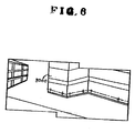
- Fig. 6 is a diagram illustrating still another method for using the surveying apparatus with the picking-up device according to the first embodiment of the present invention.
- Fig. 7 is a diagram illustrating the electrical configuration of a surveying apparatus with a picking-up device according to a second embodiment of the present invention.
- Fig. 1 shows a case in which a distance is measured using a distance measurement target 2000 and a surveying apparatus 1000 with a picking-up device 100.
- the picking-up device 100 is used to convert image device data into digital data.
- An example of the picking-up device 100 is an electronic camera such as a digital camera.
- the surveying apparatus 1000 includes a distance measuring unit 300 for measuring the distance from a measurement target, and the picking-up device 100 is mounted above the distance measuring unit 300.
- the picking-up device 100 picks up an image by use of an image sensor such as a CCD.
- the picking-up device 100 may be incorporated in the surveying apparatus 1000 or it may be attached to the surveying apparatus 1000 afterward, that is, any picking-up device of type operable in combination with the surveying apparatus 1000 as a single unit can be used.
- the collimation direction of the distance measuring light from the distance-measuring unit 300 is approximately in parallel with the collimation direction of the picking-up device 100 with a given interval spaced.
- the distance measurement target 2000 has a reflection prism 2100 (retroreflection prism) at the position of its measurement target. If the reflection prism 2100 is not required, the distance of the measurement target is directly measured.
- Fig. 2 is a diagram showing -the electrical configuration of the surveying apparatus 1000 with the picking-up device 100.
- the surveying apparatus 1000 with the picking-up device 100 comprises the picking-up device 100, the distance-measuring unit 300, a distance calculating unit 310, an operation unit (CPU) 400, an angle calculating unit 410, a horizontal angle encoder 420, an ascending/descending vertical angle encoder 430, a storage unit 500, a display unit 600, and an input/output unit 700.
- the picking-up device 100 is used to capture the image of the distance measurement target 2000 and its background.
- the picking-up device 100 is of type capable of outputting digital data, and stores as information each pixel corresponding to one element of the image sensor, thereby making it possible to perform operation on the stored information.
- the distance-measuring unit 300 emits a distance measuring light, and receives the reflected light from the target point 2000.
- the distance calculating unit 310 target 2000 by use of the phase and time differences, etc. of the reflected light obtained by the distance measuring unit 300.
- the angle-calculating unit 410 is used to calculate the horizontal and ascending/descending vertical angles, and the horizontal angle encoder 420 detects the amount of horizontal rotation from a reference direction to the collimation direction of the distance-measuring unit 300.
- the ascending/descending vertical angle encoder 430 detects the amount of ascending/descending vertical rotation from the horizontal direction or the zenith to the collimation direction of the distance-measuring unit 300.
- the angle-calculating unit 410 calculates the horizontal angle and the ascending/descending vertical angle by use of the amount of horizontal rotation and the amount of ascending/descending vertical rotation detected by the horizontal angle encoder 420 and the ascending/descending vertical angle encoder 430, respectively.
- the storage unit 500 stores basic programs for controlling the entire surveying apparatus 1000 with the picking-up device 100 as well as image data obtained from the picking-up device 100 and distance measurement data, data of horizontal and ascending/descending vertical angles, etc. obtained from the distance measuring unit 300.
- the basic programs include basic programs for data indication, etc. for the surveying apparatus 1000, a data processing program, and a data input/output program.
- the display unit 600 displays angle data, distance data, etc. and uses a liquid crystal display.
- a liquid crystal display To display image data, it is necessary to employ a black and white liquid crystal display or a color liquid crystal display capable of expressing shades of gray, or any display means having higher display quality.
- the input/output unit 700 is designed to output data stored in the storage unit 500, and receive data from a computer, a survey program, etc.
- Fig. 3 is a flowchart of the processing of image data and survey data.
- the picking-up device 100 obtains image data.
- the distance-measuring unit 300 emits a distance measuring light and receives the reflected light from the distance measurement target 2000.
- the phase and time differences, etc. of the reflected light are used to calculate the distance of the distance measurement target 2000.
- the angle-calculating unit 410 calculates the horizontal angle and the ascending/descending vertical angle at S2.
- S3 sends the image data obtained at S1, the distance data obtained at S2, the amount of deviation in the collimation (parallel deviation amount) of the picking-up device, etc. to the operation unit (CPU) 400 so that a mark indicating the survey collimation position is displayed in the image (data) based on the deviation amount of the collimation of the picking-up device from the distance measurement data included in the survey data.
- the operation unit CPU 400 calculates how many pixels the distance measurement target 2000 is apart from the collimation position of the picking-up device 100 based on the distance of the distance measurement target 2000 and the deviation amount. That is, the coordinates X and Y on the X coordinate axis and Y coordinate axis corresponding to the position of the distance measurement target 200 are determined. Then, S5 stores the data calculated at S4 into a second storage unit 520 as well as selectively displaying the data on the display unit 600.
- S6 calculates the position of the survey target 2000 from the survey data obtained at S2. Furthermore, S7 determines the corresponding relationship between the image data obtained at S1 and the position (the X and the Y coordinates on the X and the X axes) of the survey target 2000 obtained at S6.
- S8 stores the data calculated at S7 into a first storage unit 510 as well as displaying the data on the display unit 600.
- the storage unit 500 comprises the first storage unit 510 and the second storage unit 520.
- Fig. 4 shows a prism-less system in which the survey target 2000 does not use the reflection prism 2100 (retroreflection prism).
- the picking-up device 100 captures the background image in which the points P1, P2, and P3 on the survey target 2000 are indicated by cross-hair marks, and their three-dimensional coordinates (X, Y, Z) are also indicated. It should be noted that each cross-hair mark corresponds to a measurement target position mark.
- the operation unit (CPU) 400 calculates the three-dimensional coordinates of the survey target 2000 by use of the data obtained from the distance calculating unit 310 and the angle calculating unit 410 and obtains how many pixels the survey target 2000 is apart from the collimation position of the picking-up device 100 to indicate the position of the survey target 2000 as a cross-hair mark. Thus, it is possible to display the survey target 2000 together with its background image.
- the portions of the background behind the points P1, P2, and P3 on the survey target 2000 can be enlarged on the display.
- Fig. 5 shows a case in which the surveying apparatus 1000 with the picking-up device 100 is intermittently rotated horizontally so that the picking-up device 100 captures a plurality of images.
- a panorama-like 360-degree encircling image (from +180° to -180°) can be produced. It is possible to set and measure another survey target 2000, and display another survey target 2000 together with its background image using this produced panorama-like image.
- the picking-up device 100 captures a background image for which a plurality of survey targets 2000 is set. These survey targets 2000 are set and displayed along a continuous line. Specifically in Fig. 6, the continuous line is formed by connecting points having a specific height in a building 3000.
- a separate display operation device may be provided such that: when measurement data (the three-dimensional coordinates X, Y, and Z of the survey target 2000) is displayed, image data associated with the survey data is selectively displayed; and when image data is displayed, the image data itself or measurement data associated with a cross-hair mark (measurement target position mark) indicated in the image is selectively displayed.
- a surveying apparatus 1002 with a picking-up device 100 comprises a first picking-up device 110, a second picking-up device 120, a distance measuring unit 300, a distance calculating unit 310, an operation unit (CPU) 400, an angle calculating unit 410, a horizontal angle encoder 420, an ascending/descending vertical angle encoder 430, a storage unit 500, a display unit 600, and an input/output unit 700.
- the first picking-up device 110 telescopically captures an image in a direction parallel with the collimation direction of the surveying apparatus 1002.
- the second picking-up device 120 captures an image of a wide photographing range including the photographing range of the first picking-up device 110.
- the collimation directions of the first picking-up device 110, the second picking-up device 120, and the surveying apparatus 1002 are in parallel one another.
- Measurement data obtained by the surveying apparatus 1002 can be associated with image data obtained by the first picking-up device 110 and the second picking-up device 120.
- cross-hair marks (measurement target position marks) can be indicated in the image (data).
- the first storage unit 510 is designed to store the measurement data associated with the image data while the second storage unit 520 is designed to store the image data associated with the measurement data.
- the measurement data and/or image data stored in the first storage unit 510 and the second storage unit 520 can be displayed on the display unit as necessary.
- the first picking-up device 110 may form a coaxial optical system with the distance measuring optical system of the surveying apparatus 1002. Since the distance measuring light is generally invisible light, a dichroic prism, which separates one wavelength band from the other, is used to separate the invisible light from the visible light so as to be able to form the coaxial optical system. If this optical system has a collimation optical system and a distance measuring optical system, a half mirror is used to separate the distance measuring light by use of a dichroic prism, and supply it to the picking-up device.
- the image data obtained by the first picking-up device 110 and the image data obtained by the second picking-up device 120 are associated with each other by both the measurement data and the cross-hair marks (target position marks) so that the image data obtained by the first picking-up device 110 can be easily displayed as an enlarged image using a cross-hair mark (target position mark) attached to the image data obtained by the second picking-up device 120.
- the image data obtained by the first picking-up device 110 and the image data obtained by the second picking-up device 120 can be associated with each other by both the measurement data and the cross-hair marks (target position marks).
- an electronic storage medium such as an FD, a CD, a DVD, a RAM, a ROM, or a memory card, storing a program which specifies a procedure for: causing the operation unit (CPU) 400 to associate measurement data obtained by the surveying apparatus 1000 having the picking-up device 100 with image data obtained by the picking-up device 100 having an optical axis approximately parallel with an optical axis of the surveying apparatus 1000 and display a cross-hair mark (a measurement target position mark) in the image data, the measurement data including a distance, a horizontal angle, and an altitude angle of the measurement target 2000; causing the first storage unit 510 to store the measurement data associated with the image data; causing the second storage unit 520 to store the image data associated with the measurement data; and causing the display unit 600 to, when necessary, display at least one of the measurement data and the image data stored in the first storage unit 510 and the second storage unit 520, respectively.
- any electronic storage medium can be used as the above electronic storage medium as long
- a surveying apparatus measures a distance, a horizontal angle, and an altitude angle of a measurement target by use of reflected light
- the surveying apparatus is configured such that a picking-up device can be connected to the surveying apparatus, the picking-up device having an optical axis approximately parallel with an optical axis of the surveying apparatus, the surveying apparatus comprising: an operation unit for associating measurement data obtained by the surveying apparatus with image data obtained by the picking-up device and displaying a measurement target position mark in the image data; a first storage unit for storing the measurement data associated with the image data; a second storage unit for storing the image data associated with the measurement data; and a display unit for, when necessary, displaying at least one of the measurement data and the image data stored in the first storage unit and the second storage unit, respectively.
- the present invention can display both a measurement target position mark and measurement data in image data, resulting in efficient survey work with superb effect.
Abstract
Description
- The present invention relates to both a surveying apparatus with a picking-up device and an electronic storage medium, and particularly to a surveying apparatus capable of combining a background image captured by a picking-up device and survey data obtained by the survey device, and displaying the combined image on a display unit.
- In survey work, a horizontal angle, an altitude angle, a distance, etc. of a target point is measured from a reference point. The measured data is used to calculate the location of the target point in a map. Surveying provides reference data for drafting of a work plan, site execution, construction work for a building, etc. It is necessary to obtain the geographic locations of lands owned by other people and existing buildings before carrying out any civil or construction work. Surveying is work for specifying these existing locations as well as planned ones.
- For example, before carrying out civil or construction work at a target place, a survey of the place is conducted. Based on the survey data of the current conditions of the place, a work plan is drafted. After drafting the work plan, another survey is conducted to specify the location determined by the work plan. Site execution, construction of a building, etc. are performed according to the work plan and the survey results.
- In most small-scale survey companies, the same person is responsible for surveying and drafting a work plan based on the survey results, acting as both a person in charge of surveying and a person in charge of work. In such a case, since the person in charge of work knows the site very well, the person can smoothly draft the plan. However, human memory tends to be ambiguous, causing a small discrepancy in some cases. This may lead to a delay of work or inappropriate work, sometimes raising a serious problem.
- In many large-scale survey companies, on the other hand, surveying and drafting of a work plan are each carried out by a respective person in charge separately, considering the work efficiency. The person in charge of work prepares a work plan with reference to survey data, site pictures, etc. This division of work may cause a discrepancy between the understanding of the site by the person in charge of surveying and that by the person in charge of work, imposing an unnecessary burden on site workers and thereby causing serious problems such as a large delay of work, execution of inappropriate work, and increased work cost.
- A surveying apparatus according to the present invention is capable of combining a background image captured by a picking-up device and survey data obtained by the surveying apparatus and displaying the combined image on a display unit, wherein the surveying apparatus is configured such that the picking-up device can be connected to the surveying apparatus, the picking-up device having an optical axis approximately parallel with an optical axis of the surveying apparatus, the surveying apparatus comprising: an operation unit for associating measurement data obtained by the surveying apparatus with image data obtained by the picking-up data and displaying a measurement target position mark in the image data; a first storage unit for storing the measurement data associated with the image data; a second storage unit for storing the image data associated with the measurement data; and a display unit for, when necessary, displaying at least one of the measurement data and the image data stored in the first storage unit and the second storage unit, respectively.
- The following drawings show embodiments of the present invention.
- Fig. 1 is a diagram illustrating a surveying apparatus with a picking-up device according to a first embodiment of the present invention.
- Fig. 2 is a diagram illustrating the electrical configuration of the surveying apparatus with the picking-up device according to the first embodiment of the present invention.
- Fig. 3 is a diagram illustrating the operation of the surveying apparatus with the picking-up device according to the first embodiment of the present invention.
- Fig. 4 is a diagram illustrating a method for using the surveying apparatus with the picking-up device according to the first embodiment of the present invention.
- Fig. 5 is a diagram illustrating another method for using the surveying apparatus with the picking-up device according to the first embodiment of the present invention.
- Fig. 6 is a diagram illustrating still another method for using the surveying apparatus with the picking-up device according to the first embodiment of the present invention.
- Fig. 7 is a diagram illustrating the electrical configuration of a surveying apparatus with a picking-up device according to a second embodiment of the present invention.
- Preferred embodiments of the present invention will be described with reference to the accompanying drawings.
- Fig. 1 shows a case in which a distance is measured using a
distance measurement target 2000 and asurveying apparatus 1000 with a picking-updevice 100. The picking-updevice 100 is used to convert image device data into digital data. An example of the picking-updevice 100 is an electronic camera such as a digital camera. - The
surveying apparatus 1000 includes adistance measuring unit 300 for measuring the distance from a measurement target, and the picking-updevice 100 is mounted above thedistance measuring unit 300. The picking-updevice 100 picks up an image by use of an image sensor such as a CCD. The picking-updevice 100 may be incorporated in thesurveying apparatus 1000 or it may be attached to thesurveying apparatus 1000 afterward, that is, any picking-up device of type operable in combination with thesurveying apparatus 1000 as a single unit can be used. - The collimation direction of the distance measuring light from the distance-
measuring unit 300 is approximately in parallel with the collimation direction of the picking-updevice 100 with a given interval spaced. - The
distance measurement target 2000 has a reflection prism 2100 (retroreflection prism) at the position of its measurement target. If thereflection prism 2100 is not required, the distance of the measurement target is directly measured. - Fig. 2 is a diagram showing -the electrical configuration of the
surveying apparatus 1000 with the picking-updevice 100. - The
surveying apparatus 1000 with the picking-updevice 100 comprises the picking-updevice 100, the distance-measuring unit 300, adistance calculating unit 310, an operation unit (CPU) 400, anangle calculating unit 410, a horizontal angle encoder 420, an ascending/descendingvertical angle encoder 430, astorage unit 500, adisplay unit 600, and an input/output unit 700. - The picking-up
device 100 is used to capture the image of thedistance measurement target 2000 and its background. The picking-updevice 100 is of type capable of outputting digital data, and stores as information each pixel corresponding to one element of the image sensor, thereby making it possible to perform operation on the stored information. - The distance-
measuring unit 300 emits a distance measuring light, and receives the reflected light from thetarget point 2000. Thedistance calculating unit 310target 2000 by use of the phase and time differences, etc. of the reflected light obtained by thedistance measuring unit 300. - The angle-calculating
unit 410 is used to calculate the horizontal and ascending/descending vertical angles, and the horizontal angle encoder 420 detects the amount of horizontal rotation from a reference direction to the collimation direction of the distance-measuring unit 300. - Similarly, the ascending/descending
vertical angle encoder 430 detects the amount of ascending/descending vertical rotation from the horizontal direction or the zenith to the collimation direction of the distance-measuring unit 300. - The angle-calculating
unit 410 calculates the horizontal angle and the ascending/descending vertical angle by use of the amount of horizontal rotation and the amount of ascending/descending vertical rotation detected by the horizontal angle encoder 420 and the ascending/descendingvertical angle encoder 430, respectively. - The
storage unit 500 stores basic programs for controlling theentire surveying apparatus 1000 with the picking-updevice 100 as well as image data obtained from the picking-updevice 100 and distance measurement data, data of horizontal and ascending/descending vertical angles, etc. obtained from thedistance measuring unit 300. - The basic programs include basic programs for data indication, etc. for the
surveying apparatus 1000, a data processing program, and a data input/output program. - The
display unit 600 displays angle data, distance data, etc. and uses a liquid crystal display. To display image data, it is necessary to employ a black and white liquid crystal display or a color liquid crystal display capable of expressing shades of gray, or any display means having higher display quality. - The input/
output unit 700 is designed to output data stored in thestorage unit 500, and receive data from a computer, a survey program, etc. - Fig. 3 is a flowchart of the processing of image data and survey data.
- At step 1 (each step is hereinafter referred to by its shortened form such as "S1" for
step 1, "S2" forstep 2, and so on), the picking-updevice 100 obtains image data. At S2, the distance-measuring unit 300 emits a distance measuring light and receives the reflected light from thedistance measurement target 2000. The phase and time differences, etc. of the reflected light are used to calculate the distance of thedistance measurement target 2000. Furthermore, the angle-calculatingunit 410 calculates the horizontal angle and the ascending/descending vertical angle at S2. - Next, S3 (step 3) sends the image data obtained at S1, the distance data obtained at S2, the amount of deviation in the collimation (parallel deviation amount) of the picking-up device, etc. to the operation unit (CPU) 400 so that a mark indicating the survey collimation position is displayed in the image (data) based on the deviation amount of the collimation of the picking-up device from the distance measurement data included in the survey data.
- At S4, the
operation unit CPU 400 calculates how many pixels thedistance measurement target 2000 is apart from the collimation position of the picking-updevice 100 based on the distance of thedistance measurement target 2000 and the deviation amount. That is, the coordinates X and Y on the X coordinate axis and Y coordinate axis corresponding to the position of the distance measurement target 200 are determined. Then, S5 stores the data calculated at S4 into a second storage unit 520 as well as selectively displaying the data on thedisplay unit 600. - S6 calculates the position of the
survey target 2000 from the survey data obtained at S2. Furthermore, S7 determines the corresponding relationship between the image data obtained at S1 and the position (the X and the Y coordinates on the X and the X axes) of thesurvey target 2000 obtained at S6. - S8 stores the data calculated at S7 into a first storage unit 510 as well as displaying the data on the
display unit 600. - It should be noted that the
storage unit 500 comprises the first storage unit 510 and the second storage unit 520. - Methods of using the present invention will be described below.
- Fig. 4 shows a prism-less system in which the
survey target 2000 does not use the reflection prism 2100 (retroreflection prism). In the present embodiment, a case is shown where thesurvey target 2000 is a dangerous cliff. The picking-updevice 100 captures the background image in which the points P1, P2, and P3 on thesurvey target 2000 are indicated by cross-hair marks, and their three-dimensional coordinates (X, Y, Z) are also indicated. It should be noted that each cross-hair mark corresponds to a measurement target position mark. - As described above, the operation unit (CPU) 400 calculates the three-dimensional coordinates of the
survey target 2000 by use of the data obtained from thedistance calculating unit 310 and theangle calculating unit 410 and obtains how many pixels thesurvey target 2000 is apart from the collimation position of the picking-updevice 100 to indicate the position of thesurvey target 2000 as a cross-hair mark. Thus, it is possible to display thesurvey target 2000 together with its background image. - Furthermore, the portions of the background behind the points P1, P2, and P3 on the
survey target 2000 can be enlarged on the display. - Fig. 5 shows a case in which the
surveying apparatus 1000 with the picking-updevice 100 is intermittently rotated horizontally so that the picking-updevice 100 captures a plurality of images. By horizontally aligning these images, a panorama-like 360-degree encircling image (from +180° to -180°) can be produced. It is possible to set and measure anothersurvey target 2000, and display anothersurvey target 2000 together with its background image using this produced panorama-like image. - With this, it is possible to set the
survey target 2000 in all directions (panorama-like arrangement from +180° to -180°) on a horizontal plane. - Incidentally, when the above plurality of images are simultaneously displayed at intervals determined based on the survey data by use of the measurement data and image data obtained by the
surveying apparatus 1000 with the picking-updevice 100, only one image may be used in the overlapped portion of each two adjacent images to create the panorama-like 360-degree encircling image. - In Fig. 6, the picking-up
device 100 captures a background image for which a plurality ofsurvey targets 2000 is set. These survey targets 2000 are set and displayed along a continuous line. Specifically in Fig. 6, the continuous line is formed by connecting points having a specific height in abuilding 3000. - By selecting one of the cross-hair marks (measurement target position marks) indicated in the continuous image, it is possible to display the corresponding enlarged background image (image data) by use of the
image device 100. - It should be noted that a separate display operation device may be provided such that: when measurement data (the three-dimensional coordinates X, Y, and Z of the survey target 2000) is displayed, image data associated with the survey data is selectively displayed; and when image data is displayed, the image data itself or measurement data associated with a cross-hair mark (measurement target position mark) indicated in the image is selectively displayed.
- A surveying apparatus 1002 with a picking-up
device 100 according to a second embodiment of the present invention comprises a first picking-up device 110, a second picking-up device 120, adistance measuring unit 300, adistance calculating unit 310, an operation unit (CPU) 400, anangle calculating unit 410, a horizontal angle encoder 420, an ascending/descendingvertical angle encoder 430, astorage unit 500, adisplay unit 600, and an input/output unit 700. - The first picking-up device 110 telescopically captures an image in a direction parallel with the collimation direction of the surveying apparatus 1002.
- The second picking-up device 120 captures an image of a wide photographing range including the photographing range of the first picking-up device 110.
- The collimation directions of the first picking-up device 110, the second picking-up device 120, and the surveying apparatus 1002 are in parallel one another.
- Measurement data obtained by the surveying apparatus 1002 can be associated with image data obtained by the first picking-up device 110 and the second picking-up device 120. In addition, cross-hair marks (measurement target position marks) can be indicated in the image (data).
- Further, the first storage unit 510 is designed to store the measurement data associated with the image data while the second storage unit 520 is designed to store the image data associated with the measurement data. With this arrangement, the measurement data and/or image data stored in the first storage unit 510 and the second storage unit 520 can be displayed on the display unit as necessary.
- It should be noted that the first picking-up device 110 may form a coaxial optical system with the distance measuring optical system of the surveying apparatus 1002. Since the distance measuring light is generally invisible light, a dichroic prism, which separates one wavelength band from the other, is used to separate the invisible light from the visible light so as to be able to form the coaxial optical system. If this optical system has a collimation optical system and a distance measuring optical system, a half mirror is used to separate the distance measuring light by use of a dichroic prism, and supply it to the picking-up device.
- Furthermore, the image data obtained by the first picking-up device 110 and the image data obtained by the second picking-up device 120 are associated with each other by both the measurement data and the cross-hair marks (target position marks) so that the image data obtained by the first picking-up device 110 can be easily displayed as an enlarged image using a cross-hair mark (target position mark) attached to the image data obtained by the second picking-up device 120.
- Thus, according to the second embodiment, by selecting a cross-hair mark (target position mark) of the image data obtained by the second picking-up device 120, it is possible to display the corresponding image (data) obtained by the first picking-up device 110. Furthermore, the image data obtained by the first picking-up device 110 and the image data obtained by the second picking-up device 120 can be associated with each other by both the measurement data and the cross-hair marks (target position marks).
- With this arrangement, it is possible to obtain a clearer image by enlarging an image of digital data, increasing the number of applications to which the image data can be applied.
- It should be noted that since the other configurations and effects of the second embodiment are the same as those of the first embodiment, their explanation will be omitted.
- Further, there may be provided an electronic storage medium such as an FD, a CD, a DVD, a RAM, a ROM, or a memory card, storing a program which specifies a procedure for: causing the operation unit (CPU) 400 to associate measurement data obtained by the
surveying apparatus 1000 having the picking-updevice 100 with image data obtained by the picking-updevice 100 having an optical axis approximately parallel with an optical axis of thesurveying apparatus 1000 and display a cross-hair mark (a measurement target position mark) in the image data, the measurement data including a distance, a horizontal angle, and an altitude angle of themeasurement target 2000; causing the first storage unit 510 to store the measurement data associated with the image data; causing the second storage unit 520 to store the image data associated with the measurement data; and causing thedisplay unit 600 to, when necessary, display at least one of the measurement data and the image data stored in the first storage unit 510 and the second storage unit 520, respectively. It should be noted that any electronic storage medium can be used as the above electronic storage medium as long as it can store a program for controlling the operation unit (CPU) 400, etc. - Configured as described above, a surveying apparatus according to the present invention measures a distance, a horizontal angle, and an altitude angle of a measurement target by use of reflected light, wherein the surveying apparatus is configured such that a picking-up device can be connected to the surveying apparatus, the picking-up device having an optical axis approximately parallel with an optical axis of the surveying apparatus, the surveying apparatus comprising: an operation unit for associating measurement data obtained by the surveying apparatus with image data obtained by the picking-up device and displaying a measurement target position mark in the image data; a first storage unit for storing the measurement data associated with the image data; a second storage unit for storing the image data associated with the measurement data; and a display unit for, when necessary, displaying at least one of the measurement data and the image data stored in the first storage unit and the second storage unit, respectively. Thus, the present invention can display both a measurement target position mark and measurement data in image data, resulting in efficient survey work with superb effect.
- Furthermore, it is not necessary to draft a work plan while referring to survey data, site pictures, etc., eliminating occurrence of a discrepancy at site and preventing delay of work and execution of inappropriate work, etc.
Claims (8)
- A surveying apparatus for measuring a distance, a horizontal angle, and an altitude angle of a measurement target by use of reflected light, said surveying apparatus comprising:a picking-up device capable of being connected to said surveying apparatus, said picking-up device having an optical axis approximately parallel with an optical axis of said surveying apparatus;an operation unit for associating measurement data obtained by said surveying apparatus with image data obtained by said picking-up device, and displaying a measurement target position mark in said image data;a first storage unit for storing said measurement data associated with said image data;a second storage unit for storing said image data associated with said measurement data; anda display unit for, when necessary, displaying at least one of said measurement data and said image data stored in said first storage unit and said second storage unit, respectively.
- A surveying apparatus for measuring a distance, a horizontal angle, and an altitude angle of a measurement target by use of reflected light, said surveying apparatus comprising:a first picking-up device for capturing an image in a collimation direction of said surveying apparatus;a second picking-up device for capturing an image in a wide photographing range including a photographing range of said first picking-up device;an operation unit for associating measurement data obtained by said surveying apparatus with image data obtained by said first picking-up device and said second picking-up device, and displaying a measurement target position mark in said image data;a first storage unit for storing said measurement data associated with said image data;a second storage unit for storing said image data associated with said measurement data; anda display unit for, when necessary, displaying at least one of said measurement data and said image data stored in said first storage unit and said second storage unit, respectively.
- The surveying apparatus according to claim 1 or 2, wherein said surveying apparatus is provided with a separate display operation device for, based on said measurement data and image data obtained by said surveying apparatus, operating such that, when said measurement data is displayed, said image data associated with said measurement data is selectively displayed; and when said image data is displayed, said image data or said measurement data associated with said measurement target position mark displayed in said image is selectively displayed.
- The surveying apparatus according to any one of claims 1 to 3, wherein based on said measurement data and image data obtained by said surveying apparatus, said surveying apparatus displays a plurality of pieces of said image data at the same time at intervals determined based on survey data, displaying only one piece of said image data in an overlapped portion of each two adjacent pieces of said image data to produce a single continuous image.
- The surveying apparatus according to claim 4, wherein selecting a measurement target position mark indicated in said continuous image displays image data associated with said measurement target position mark.
- The surveying apparatus according to any one of claims 2 to 5, wherein selecting a target position mark of said image data obtained by said second picking-up device displays associated image data obtained by said first picking-up device.
- The surveying apparatus according to any one of claims 2 to 5, wherein said image data obtained by said first picking-up device and said image data obtained by said second picking-up device are associated with each other by both said measurement data and a target position mark.
- An electronic storage medium including an FD, a CD, a DVD, a RAM, a ROM, or a memory card, storing a program which specifies a procedure for:causing an operation unit to associate measurement data obtained by a surveying apparatus with image data obtained by a picking-up device having an optical axis approximately parallel with an optical axis of said surveying apparatus and display a measurement target position mark in said image data, said measurement data including a distance, a horizontal angle, and an altitude angle of a measurement target;causing a first storage unit to store said measurement data associated with said image data;causing a second storage unit to store said image data associated with said measurement data; andcausing a display unit to, when necessary, display at least one of said measurement data and said image data stored in said first storage unit and said second storage unit, respectively.
Applications Claiming Priority (2)
| Application Number | Priority Date | Filing Date | Title |
|---|---|---|---|
| JP2000403306A JP4356050B2 (en) | 2000-12-28 | 2000-12-28 | Surveyor and electronic storage medium |
| JP2000403306 | 2000-12-28 |
Publications (3)
| Publication Number | Publication Date |
|---|---|
| EP1219925A2 true EP1219925A2 (en) | 2002-07-03 |
| EP1219925A3 EP1219925A3 (en) | 2004-06-02 |
| EP1219925B1 EP1219925B1 (en) | 2011-03-16 |
Family
ID=18867458
Family Applications (1)
| Application Number | Title | Priority Date | Filing Date |
|---|---|---|---|
| EP01130623A Expired - Lifetime EP1219925B1 (en) | 2000-12-28 | 2001-12-27 | Surveying apparatus |
Country Status (5)
| Country | Link |
|---|---|
| US (1) | US6563574B2 (en) |
| EP (1) | EP1219925B1 (en) |
| JP (1) | JP4356050B2 (en) |
| CN (1) | CN1362612A (en) |
| DE (1) | DE60144218D1 (en) |
Cited By (11)
| Publication number | Priority date | Publication date | Assignee | Title |
|---|---|---|---|---|
| WO2005017644A2 (en) | 2003-08-13 | 2005-02-24 | Topcon Corp | 3-dimensional measurement device and electronic storage medium |
| EP1744122A2 (en) | 2005-07-11 | 2007-01-17 | Kabushiki Kaisha Topcon | Geographic data collecting system |
| EP1760430A2 (en) * | 2005-07-11 | 2007-03-07 | Kabushiki Kaisha Topcon | Geographic data collecting system |
| EP1469281A3 (en) * | 2003-04-14 | 2008-01-16 | Kabushiki Kaisha TOPCON | Electronic surveying apparatus |
| US8149388B2 (en) | 2007-10-10 | 2012-04-03 | Trimble Jena Gmbh | Surveying apparatus for tracking and surveying an object |
| US8280677B2 (en) | 2008-03-03 | 2012-10-02 | Kabushiki Kaisha Topcon | Geographical data collecting device |
| US8368875B2 (en) | 2007-01-26 | 2013-02-05 | Trimble Jena Gmbh | Optical instrument and method for obtaining distance and image information |
| EP2489980A3 (en) * | 2011-02-21 | 2013-07-24 | Kabushiki Kaisha Topcon | Omnidirectional image measuring instrument |
| US8717432B2 (en) | 2008-03-04 | 2014-05-06 | Kabushiki Kaisha Topcon | Geographical data collecting device |
| US8934009B2 (en) | 2010-09-02 | 2015-01-13 | Kabushiki Kaisha Topcon | Measuring method and measuring device |
| CN104764435A (en) * | 2014-01-07 | 2015-07-08 | 广州市科创电脑技术开发有限公司 | Intelligent surveying and mapping system and method |
Families Citing this family (44)
| Publication number | Priority date | Publication date | Assignee | Title |
|---|---|---|---|---|
| EP2306228A1 (en) * | 1998-05-25 | 2011-04-06 | Panasonic Corporation | Range finder device and camera |
| JP5037765B2 (en) * | 2001-09-07 | 2012-10-03 | 株式会社トプコン | Operator guidance system |
| AT412032B (en) * | 2001-12-19 | 2004-08-26 | Riegl Laser Measurement Sys | METHOD FOR RECORDING AN OBJECT SPACE |
| JP4004316B2 (en) * | 2002-03-20 | 2007-11-07 | 株式会社トプコン | Surveying device and method for acquiring image data using surveying device |
| US7075634B2 (en) * | 2002-06-28 | 2006-07-11 | Pentax Corporation | Surveying system |
| JP3937154B2 (en) * | 2002-06-28 | 2007-06-27 | 株式会社トプコン | Position detection device |
| AU2003258898A1 (en) * | 2002-08-09 | 2004-02-25 | Surveylab Group Limited | Mobile instrument, viewing device, and methods of processing and storing information |
| JP3947455B2 (en) * | 2002-11-11 | 2007-07-18 | ペンタックス株式会社 | Surveyor with automatic collimation function and ranging function |
| EP1517116A1 (en) * | 2003-09-22 | 2005-03-23 | Leica Geosystems AG | Method and device for the determination of the actual position of a geodesic instrument |
| JP4279111B2 (en) * | 2003-10-14 | 2009-06-17 | 株式会社トプコン | Measuring method and measuring system |
| US7199872B2 (en) * | 2004-05-18 | 2007-04-03 | Leica Geosystems Ag | Method and apparatus for ground-based surveying in sites having one or more unstable zone(s) |
| JP4427389B2 (en) * | 2004-06-10 | 2010-03-03 | 株式会社トプコン | Surveying instrument |
| JP4398314B2 (en) * | 2004-07-09 | 2010-01-13 | 株式会社 ソキア・トプコン | Surveying instrument and marking point transfer processing program |
| US7764365B2 (en) * | 2004-07-23 | 2010-07-27 | Trimble Navigation Limited | Combination laser detector and global navigation satellite receiver system |
| EP1669776A1 (en) * | 2004-12-11 | 2006-06-14 | Leica Geosystems AG | Handheld distance measuring apparatus and a method therefore |
| JP4944462B2 (en) * | 2006-03-14 | 2012-05-30 | 株式会社トプコン | Geographic data collection device |
| JP2008014682A (en) * | 2006-07-03 | 2008-01-24 | Pentax Industrial Instruments Co Ltd | Surveying instrument |
| DE602006014263D1 (en) * | 2006-07-03 | 2010-06-24 | Trimble Ab | Surveying instrument and method for controlling a surveying instrument |
| JP5127323B2 (en) * | 2006-07-03 | 2013-01-23 | タイワン インスツルメント カンパニー リミテッド | Surveying instrument |
| JP5133620B2 (en) * | 2006-07-03 | 2013-01-30 | タイワン インスツルメント カンパニー リミテッド | Surveying instrument |
| JP5028164B2 (en) * | 2006-07-03 | 2012-09-19 | タイワン インスツルメント カンパニー リミテッド | Surveying instrument |
| KR100791389B1 (en) * | 2006-12-26 | 2008-01-07 | 삼성전자주식회사 | Apparatus and method for measuring distance using structured light |
| WO2008089791A1 (en) * | 2007-01-26 | 2008-07-31 | Trimble Jena Gmbh | Optical instrument and method for obtaining distance and image information |
| JP5263804B2 (en) | 2007-04-20 | 2013-08-14 | 株式会社トプコン | Multipoint measuring method and surveying device |
| JP5150229B2 (en) * | 2007-12-07 | 2013-02-20 | 株式会社トプコン | Surveying system |
| JP5150234B2 (en) * | 2007-12-14 | 2013-02-20 | 株式会社トプコン | Surveying equipment |
| JP5550853B2 (en) * | 2009-06-09 | 2014-07-16 | 株式会社ソーキ | Surveying device with image transmission function and surveying method |
| EP2569595B1 (en) | 2010-05-12 | 2018-07-04 | Leica Geosystems AG | Surveying instrument |
| DE102010061725A1 (en) * | 2010-11-22 | 2012-05-24 | Hilti Aktiengesellschaft | Rotary laser device having a tilted laser plane and method of aligning a rotary laser device |
| US8539685B2 (en) | 2011-01-20 | 2013-09-24 | Trimble Navigation Limited | Integrated surveying and leveling |
| JP5753409B2 (en) | 2011-03-07 | 2015-07-22 | 株式会社トプコン | Panorama image creation method and three-dimensional laser scanner |
| US9222771B2 (en) | 2011-10-17 | 2015-12-29 | Kla-Tencor Corp. | Acquisition of information for a construction site |
| DE102012011518B3 (en) * | 2012-06-08 | 2013-10-17 | Trimble Jena Gmbh | Geodetic objective for position determination system to determine position of e.g. landmarks, has interface formed to output signals for determination of spatial orientation of reflector relative to target point in marking direction |
| DE102012223929A1 (en) * | 2012-12-20 | 2014-06-26 | Hilti Aktiengesellschaft | Method and device for determining the two-dimensional location coordinates of a target object |
| US8988663B2 (en) * | 2013-01-22 | 2015-03-24 | Raytheon Company | Laser range finding |
| WO2015008587A1 (en) * | 2013-07-16 | 2015-01-22 | 富士フイルム株式会社 | Imaging device and three-dimensional-measurement device |
| JP6249725B2 (en) * | 2013-11-08 | 2017-12-20 | オリンパス株式会社 | Microscope system |
| JP6506531B2 (en) * | 2014-10-24 | 2019-04-24 | 株式会社ニコン・トリンブル | Surveying instrument and program |
| CN106017404B (en) * | 2016-06-22 | 2018-05-29 | 中国科学院西安光学精密机械研究所 | The detection device and method of the videographic measurment camera optical axis and auxiliary laser optical axis included angle |
| JP7037860B2 (en) | 2017-11-17 | 2022-03-17 | 株式会社トプコン | Surveying equipment and surveying equipment system |
| US11195324B1 (en) | 2018-08-14 | 2021-12-07 | Certainteed Llc | Systems and methods for visualization of building structures |
| JP7138525B2 (en) | 2018-09-25 | 2022-09-16 | 株式会社トプコン | Surveying instrument and surveying instrument system |
| JP7344732B2 (en) | 2019-09-25 | 2023-09-14 | 株式会社トプコン | Surveying equipment and surveying equipment systems |
| JP7461185B2 (en) | 2020-03-18 | 2024-04-03 | 株式会社トプコン | Surveying equipment and surveying equipment systems |
Citations (6)
| Publication number | Priority date | Publication date | Assignee | Title |
|---|---|---|---|---|
| US4682218A (en) * | 1984-10-31 | 1987-07-21 | Asahi Kogaku Kogyo Kabushiki Kaisha | Surveying instrument with image display unit |
| EP0481278A1 (en) * | 1990-10-15 | 1992-04-22 | IBP Pietzsch GmbH | Method and measuring device for locating points in space |
| EP0661519A1 (en) * | 1993-12-28 | 1995-07-05 | Kabushiki Kaisha Topcon | Surveying instrument |
| WO1999060335A1 (en) * | 1998-05-15 | 1999-11-25 | Measurement Devices Limited | Survey apparatus |
| EP1024342A1 (en) * | 1999-01-29 | 2000-08-02 | Kabushiki Kaisha Topcon | Automatic surveying equipment and three-dimensions measuring method |
| DE19922321A1 (en) * | 1999-05-14 | 2000-11-23 | Zeiss Carl Jena Gmbh | Method and arrangement for carrying out geodesic measurements utilizes a video tachymeter fitted with an electronic camera using a pixel matrix to determine coordinates of lens points. |
Family Cites Families (5)
| Publication number | Priority date | Publication date | Assignee | Title |
|---|---|---|---|---|
| US4965753A (en) * | 1988-12-06 | 1990-10-23 | Cae-Link Corporation, Link Flight | System for constructing images in 3-dimension from digital data to display a changing scene in real time in computer image generators |
| JPH032513A (en) * | 1989-05-30 | 1991-01-08 | Tatsushi Miyahara | Automatic surveying equipment |
| US5361217A (en) * | 1992-05-07 | 1994-11-01 | Fuji Photo Optical Co., Ltd. | Position measuring/plotting apparatus |
| JPH0981361A (en) * | 1995-09-12 | 1997-03-28 | Toshiba Corp | Image display method, data collection method and object specifying method |
| US6411742B1 (en) * | 2000-05-16 | 2002-06-25 | Adobe Systems Incorporated | Merging images to form a panoramic image |
-
2000
- 2000-12-28 JP JP2000403306A patent/JP4356050B2/en not_active Expired - Fee Related
-
2001
- 2001-12-27 DE DE60144218T patent/DE60144218D1/en not_active Expired - Lifetime
- 2001-12-27 CN CN01145225A patent/CN1362612A/en active Pending
- 2001-12-27 EP EP01130623A patent/EP1219925B1/en not_active Expired - Lifetime
- 2001-12-28 US US10/033,774 patent/US6563574B2/en not_active Expired - Lifetime
Patent Citations (6)
| Publication number | Priority date | Publication date | Assignee | Title |
|---|---|---|---|---|
| US4682218A (en) * | 1984-10-31 | 1987-07-21 | Asahi Kogaku Kogyo Kabushiki Kaisha | Surveying instrument with image display unit |
| EP0481278A1 (en) * | 1990-10-15 | 1992-04-22 | IBP Pietzsch GmbH | Method and measuring device for locating points in space |
| EP0661519A1 (en) * | 1993-12-28 | 1995-07-05 | Kabushiki Kaisha Topcon | Surveying instrument |
| WO1999060335A1 (en) * | 1998-05-15 | 1999-11-25 | Measurement Devices Limited | Survey apparatus |
| EP1024342A1 (en) * | 1999-01-29 | 2000-08-02 | Kabushiki Kaisha Topcon | Automatic surveying equipment and three-dimensions measuring method |
| DE19922321A1 (en) * | 1999-05-14 | 2000-11-23 | Zeiss Carl Jena Gmbh | Method and arrangement for carrying out geodesic measurements utilizes a video tachymeter fitted with an electronic camera using a pixel matrix to determine coordinates of lens points. |
Cited By (18)
| Publication number | Priority date | Publication date | Assignee | Title |
|---|---|---|---|---|
| EP1469281A3 (en) * | 2003-04-14 | 2008-01-16 | Kabushiki Kaisha TOPCON | Electronic surveying apparatus |
| EP1655573A2 (en) * | 2003-08-13 | 2006-05-10 | Kabushiki Kaisha TOPCON | 3-dimensional measurement device and electronic storage medium |
| WO2005017644A2 (en) | 2003-08-13 | 2005-02-24 | Topcon Corp | 3-dimensional measurement device and electronic storage medium |
| EP1655573A4 (en) * | 2003-08-13 | 2010-11-03 | Topcon Corp | 3-dimensional measurement device and electronic storage medium |
| US7933001B2 (en) | 2005-07-11 | 2011-04-26 | Kabushiki Kaisha Topcon | Geographic data collecting system |
| US8319952B2 (en) | 2005-07-11 | 2012-11-27 | Kabushiki Kaisha Topcon | Geographic data collecting system |
| EP1744122A3 (en) * | 2005-07-11 | 2008-06-04 | Kabushiki Kaisha Topcon | Geographic data collecting system |
| EP1760430A2 (en) * | 2005-07-11 | 2007-03-07 | Kabushiki Kaisha Topcon | Geographic data collecting system |
| EP1744122A2 (en) | 2005-07-11 | 2007-01-17 | Kabushiki Kaisha Topcon | Geographic data collecting system |
| EP1760430A3 (en) * | 2005-07-11 | 2008-06-04 | Kabushiki Kaisha Topcon | Geographic data collecting system |
| US8368875B2 (en) | 2007-01-26 | 2013-02-05 | Trimble Jena Gmbh | Optical instrument and method for obtaining distance and image information |
| US8149388B2 (en) | 2007-10-10 | 2012-04-03 | Trimble Jena Gmbh | Surveying apparatus for tracking and surveying an object |
| US8280677B2 (en) | 2008-03-03 | 2012-10-02 | Kabushiki Kaisha Topcon | Geographical data collecting device |
| US8717432B2 (en) | 2008-03-04 | 2014-05-06 | Kabushiki Kaisha Topcon | Geographical data collecting device |
| US8934009B2 (en) | 2010-09-02 | 2015-01-13 | Kabushiki Kaisha Topcon | Measuring method and measuring device |
| EP2489980A3 (en) * | 2011-02-21 | 2013-07-24 | Kabushiki Kaisha Topcon | Omnidirectional image measuring instrument |
| US9829315B2 (en) | 2011-02-21 | 2017-11-28 | Kabushiki Kaisha Topcon | Omnidirectional image measuring instrument |
| CN104764435A (en) * | 2014-01-07 | 2015-07-08 | 广州市科创电脑技术开发有限公司 | Intelligent surveying and mapping system and method |
Also Published As
| Publication number | Publication date |
|---|---|
| EP1219925B1 (en) | 2011-03-16 |
| JP2002202126A (en) | 2002-07-19 |
| US6563574B2 (en) | 2003-05-13 |
| CN1362612A (en) | 2002-08-07 |
| US20020085193A1 (en) | 2002-07-04 |
| JP4356050B2 (en) | 2009-11-04 |
| EP1219925A3 (en) | 2004-06-02 |
| DE60144218D1 (en) | 2011-04-28 |
Similar Documents
| Publication | Publication Date | Title |
|---|---|---|
| EP1219925B1 (en) | Surveying apparatus | |
| EP1607718B1 (en) | Surveying instrument and electronic storage medium | |
| EP3392612B1 (en) | Defect detection apparatus and program | |
| EP2918972B1 (en) | Method and handheld distance measuring device for generating a spatial model | |
| EP1493990B1 (en) | Surveying instrument and electronic storage medium | |
| US20060192946A1 (en) | Method and device for image processing in a geodesical measuring appliance | |
| US20060167648A1 (en) | 3-Dimensional measurement device and electronic storage medium | |
| US10506151B2 (en) | Information acquisition apparatus | |
| Höhle | Photogrammetric measurements in oblique aerial images | |
| EP3640588B1 (en) | System, method and program for determining the size of a defect | |
| KR20060117918A (en) | Noncontact three-dimensional measuring method and device | |
| JP2021039013A (en) | Wall crack measuring machine and measuring method | |
| JP4581512B2 (en) | Three-dimensional image processing apparatus, optical axis adjustment method, and optical axis adjustment support method | |
| JP4359084B2 (en) | Surveying system | |
| US11403826B2 (en) | Management system and management method using eyewear device | |
| JP4899129B2 (en) | Surveying equipment | |
| JP6722000B2 (en) | Surveying support device | |
| JP4167509B2 (en) | Surveying system | |
| US20240112327A1 (en) | Bar arrangement inspection system and bar arrangement inspection method | |
| JP2004085539A (en) | Surveying system | |
| JP4276900B2 (en) | Automatic survey system | |
| Scherer | a Circleless" 2D/3D Total STATION": a Low Cost Instrument for Surveying, Recording Point Clouds, Documentation, Image Acquisition and Visualisation | |
| CN108731644B (en) | Oblique photography mapping method and system based on vertical auxiliary line | |
| KR0129050B1 (en) | Display method for 3-dimention shape of fuel film | |
| JPH07208094A (en) | Form measurement method and device for shield segment |
Legal Events
| Date | Code | Title | Description |
|---|---|---|---|
| PUAI | Public reference made under article 153(3) epc to a published international application that has entered the european phase |
Free format text: ORIGINAL CODE: 0009012 |
|
| AK | Designated contracting states |
Kind code of ref document: A2 Designated state(s): AT BE CH CY DE DK ES FI FR GB GR IE IT LI LU MC NL PT SE TR |
|
| AX | Request for extension of the european patent |
Free format text: AL;LT;LV;MK;RO;SI |
|
| PUAL | Search report despatched |
Free format text: ORIGINAL CODE: 0009013 |
|
| AK | Designated contracting states |
Kind code of ref document: A3 Designated state(s): AT BE CH CY DE DK ES FI FR GB GR IE IT LI LU MC NL PT SE TR |
|
| AX | Request for extension of the european patent |
Extension state: AL LT LV MK RO SI |
|
| RIC1 | Information provided on ipc code assigned before grant |
Ipc: 7G 01C 15/00 B Ipc: 7G 01C 1/04 A |
|
| 17P | Request for examination filed |
Effective date: 20041104 |
|
| AKX | Designation fees paid |
Designated state(s): CH DE LI SE |
|
| 17Q | First examination report despatched |
Effective date: 20050916 |
|
| GRAP | Despatch of communication of intention to grant a patent |
Free format text: ORIGINAL CODE: EPIDOSNIGR1 |
|
| GRAS | Grant fee paid |
Free format text: ORIGINAL CODE: EPIDOSNIGR3 |
|
| GRAA | (expected) grant |
Free format text: ORIGINAL CODE: 0009210 |
|
| AK | Designated contracting states |
Kind code of ref document: B1 Designated state(s): CH DE LI SE |
|
| REG | Reference to a national code |
Ref country code: CH Ref legal event code: EP |
|
| REF | Corresponds to: |
Ref document number: 60144218 Country of ref document: DE Date of ref document: 20110428 Kind code of ref document: P |
|
| REG | Reference to a national code |
Ref country code: DE Ref legal event code: R096 Ref document number: 60144218 Country of ref document: DE Effective date: 20110428 |
|
| REG | Reference to a national code |
Ref country code: CH Ref legal event code: NV Representative=s name: HEPP WENGER RYFFEL AG |
|
| REG | Reference to a national code |
Ref country code: SE Ref legal event code: TRGR |
|
| PLBE | No opposition filed within time limit |
Free format text: ORIGINAL CODE: 0009261 |
|
| STAA | Information on the status of an ep patent application or granted ep patent |
Free format text: STATUS: NO OPPOSITION FILED WITHIN TIME LIMIT |
|
| 26N | No opposition filed |
Effective date: 20111219 |
|
| REG | Reference to a national code |
Ref country code: DE Ref legal event code: R097 Ref document number: 60144218 Country of ref document: DE Effective date: 20111219 |
|
| PGFP | Annual fee paid to national office [announced via postgrant information from national office to epo] |
Ref country code: SE Payment date: 20151211 Year of fee payment: 15 |
|
| REG | Reference to a national code |
Ref country code: SE Ref legal event code: EUG |
|
| PG25 | Lapsed in a contracting state [announced via postgrant information from national office to epo] |
Ref country code: SE Free format text: LAPSE BECAUSE OF NON-PAYMENT OF DUE FEES Effective date: 20161228 |
|
| PGFP | Annual fee paid to national office [announced via postgrant information from national office to epo] |
Ref country code: DE Payment date: 20191217 Year of fee payment: 19 |
|
| PGFP | Annual fee paid to national office [announced via postgrant information from national office to epo] |
Ref country code: CH Payment date: 20191213 Year of fee payment: 19 |
|
| REG | Reference to a national code |
Ref country code: DE Ref legal event code: R119 Ref document number: 60144218 Country of ref document: DE |
|
| REG | Reference to a national code |
Ref country code: CH Ref legal event code: PL |
|
| PG25 | Lapsed in a contracting state [announced via postgrant information from national office to epo] |
Ref country code: LI Free format text: LAPSE BECAUSE OF NON-PAYMENT OF DUE FEES Effective date: 20201231 Ref country code: CH Free format text: LAPSE BECAUSE OF NON-PAYMENT OF DUE FEES Effective date: 20201231 Ref country code: DE Free format text: LAPSE BECAUSE OF NON-PAYMENT OF DUE FEES Effective date: 20210701 |