EP1219891A2 - Candle shade - Google Patents
Candle shade Download PDFInfo
- Publication number
- EP1219891A2 EP1219891A2 EP01309842A EP01309842A EP1219891A2 EP 1219891 A2 EP1219891 A2 EP 1219891A2 EP 01309842 A EP01309842 A EP 01309842A EP 01309842 A EP01309842 A EP 01309842A EP 1219891 A2 EP1219891 A2 EP 1219891A2
- Authority
- EP
- European Patent Office
- Prior art keywords
- candle
- sleeve
- shade
- shade according
- bowl
- Prior art date
- Legal status (The legal status is an assumption and is not a legal conclusion. Google has not performed a legal analysis and makes no representation as to the accuracy of the status listed.)
- Withdrawn
Links
Images


Classifications
-
- F—MECHANICAL ENGINEERING; LIGHTING; HEATING; WEAPONS; BLASTING
- F21—LIGHTING
- F21V—FUNCTIONAL FEATURES OR DETAILS OF LIGHTING DEVICES OR SYSTEMS THEREOF; STRUCTURAL COMBINATIONS OF LIGHTING DEVICES WITH OTHER ARTICLES, NOT OTHERWISE PROVIDED FOR
- F21V35/00—Candle holders
-
- F—MECHANICAL ENGINEERING; LIGHTING; HEATING; WEAPONS; BLASTING
- F21—LIGHTING
- F21V—FUNCTIONAL FEATURES OR DETAILS OF LIGHTING DEVICES OR SYSTEMS THEREOF; STRUCTURAL COMBINATIONS OF LIGHTING DEVICES WITH OTHER ARTICLES, NOT OTHERWISE PROVIDED FOR
- F21V29/00—Protecting lighting devices from thermal damage; Cooling or heating arrangements specially adapted for lighting devices or systems
- F21V29/50—Cooling arrangements
- F21V29/502—Cooling arrangements characterised by the adaptation for cooling of specific components
- F21V29/506—Cooling arrangements characterised by the adaptation for cooling of specific components of globes, bowls or cover glasses
-
- F—MECHANICAL ENGINEERING; LIGHTING; HEATING; WEAPONS; BLASTING
- F21—LIGHTING
- F21V—FUNCTIONAL FEATURES OR DETAILS OF LIGHTING DEVICES OR SYSTEMS THEREOF; STRUCTURAL COMBINATIONS OF LIGHTING DEVICES WITH OTHER ARTICLES, NOT OTHERWISE PROVIDED FOR
- F21V3/00—Globes; Bowls; Cover glasses
- F21V3/02—Globes; Bowls; Cover glasses characterised by the shape
-
- F—MECHANICAL ENGINEERING; LIGHTING; HEATING; WEAPONS; BLASTING
- F21—LIGHTING
- F21V—FUNCTIONAL FEATURES OR DETAILS OF LIGHTING DEVICES OR SYSTEMS THEREOF; STRUCTURAL COMBINATIONS OF LIGHTING DEVICES WITH OTHER ARTICLES, NOT OTHERWISE PROVIDED FOR
- F21V37/00—Details of lighting devices employing combustion as light source, not otherwise provided for
- F21V37/02—Special adaptation for protection against draughts ; Draft controllers
Landscapes
- Engineering & Computer Science (AREA)
- General Engineering & Computer Science (AREA)
- Chemical & Material Sciences (AREA)
- Combustion & Propulsion (AREA)
- Arrangement Of Elements, Cooling, Sealing, Or The Like Of Lighting Devices (AREA)
- Fats And Perfumes (AREA)
Abstract
Description
- The present invention relates generally to shades and in particular to a candle shade to shade the wick of a candle.
- Candleholders or shades to shade the wick of a candle are known and are commonly used as decorative accents. One known candleholder includes a shade, a drip cup and frame assembly, a sleeve and a base. The base includes a socket to accommodate the bottom end of a candle. The sleeve is adapted to be placed on the top end of the candle. The drip cup and frame assembly is placed on the sleeve and supports the shade. When the wick of the candle is lit and the candle begins to melt, the shade and the drip cup and frame assembly descend with the sleeve. Unfortunately, problems exist with this candleholder design. In particular, in use, the sleeve tends to stick to the candle body, resulting in melting of the candle without the sleeve and drip cup and frame assembly descending with the candle as it melts. If this occurs, the weight of the shade and the drip cup and frame assembly can cause the candle to topple, bend or break as the candle melts. As will be appreciated, this may pose a potential fire hazard if the candle has been left unattended.
- To overcome the disadvantages associated with the above-identified candleholder, alternative candleholders have been considered. For example, German Patent Document No. 296 21 262 to Shieh discloses a candleholder including a base with a centrally disposed sleeve to receive the bottom end of a candle. An upright, inverted U-shaped bracket is mounted on the base. A sleeve is adapted to be placed on the top end of the candle. A drip cup and shade holder assembly is placed on the sleeve and accommodates the bracket. A glass sleeve surrounds the drip cup and shade holder assembly. A shade rests on the drip cup and shade holder assembly and is spaced from the glass sleeve. When the wick of the candle is lit and the candle melts, the sleeve descends with the candle as the candle melts. The shade and the drip cup and shade holder assembly in turn descend with the sleeve. The bracket guides the movement of the shade and the drip cup and shade holder assembly to inhibit toppling of the candle under the weight of the shade and the drip cup and shade holder assembly.
- U.S. Patent No. 4,755,135 to Kwok discloses a candle device including a thermally insulated candleholder having a spring therein. A cover overlies the open top of the candleholder and has an aperture therein. A candle is placed within the candleholder on top of the spring. The spring urges the candle upwardly against the cover so that the wick of the candle passes through the aperture. Thermally conductive wires extend from the aperture to the perimeter of the candle, to ensure uniform melting of the candle when the wick of the candle is lit. The candleholder can be adapted to include a shade.
- Although candleholders that include shades to shade the wick of a candle are known, improved aesthetically pleasing candle shades are desired. It is therefore an object of the present invention to provide a novel candle shade.
- Accordingly, in one aspect of the present invention there is provided a candle shade comprising:
- a sleeve adapted to receive a top end of a candle, said sleeve having an interior surface, at least one spacing element on said interior surface to space said interior surface from the candle and a stop on said sleeve to inhibit said sleeve from travelling down the candle beyond the top end thereof; and
- a shade element coupled to said sleeve and surrounding said candle adjacent said top end.
-
- Preferably, the candle shade includes at least one vent to permit air flow into the shade element adjacent the top end of the candle. In a preferred embodiment, the stop is an inwardly directed annular flange adjacent a top end of the sleeve. The flange rests on the top of the candle and defines an aperture through which the wick of the candle passes. It is also preferred that the flange has a depression surrounding the wick formed in its upper surface.
- In one embodiment, the at least one spacing element is in the form of a plurality of ribs formed on the interior surface. The ribs may be vertical and spaced about the circumference of the sleeve. Alternatively, the ribs may be circular and disposed at vertically spaced locations on the interior surface or may be helical and extend between opposite ends of the sleeve. In another embodiment, the at least one spacing elements are spaced projections formed on the interior surface.
- In one embodiment, the sleeve and the shade element are integrally formed. In this case, the shade element includes a bowl with the sleeve depending from the bowl. In another embodiment, the shade element and the sleeve are separate parts. In this case, the shade element includes a bowl with a depending second sleeve that accommodates the first sleeve. The depending second sleeve rests on a support surface formed on the outer surface of the first sleeve.
- According to yet another aspect of the present invention there is provided a candle shade comprising:
- a sleeve adapted to receive a top end of a candle, said sleeve having an inwardly directed stop thereon to rest on the top of said candle and spacing elements on an interior surface thereof, said spacing elements contacting said candle to reduce contact area between said sleeve and said candle; and
- a shade element coupled said sleeve and surrounding said candle above said top end.
-
- The present invention provides advantages in that the candle shade is easy and inexpensive to manufacture while remaining aesthetically pleasing. The candle shade is also designed to descend smoothly with the candle as the candle melts thereby avoiding situations where the candle melts faster than the candle shade descends.
- Preferred embodiments of the present invention will now be described more fully with reference to the accompanying drawings wherein like reference numerals denote like parts throughout the several views, and in which:
- Figure 1 is a side elevational view of a candle shade in accordance with the present invention;
- Figure 2 is a cross-sectional view, in side elevation, of the candle shade of Figure 1;
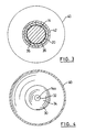
- Figure 3 is a cross-section of Figure 2 taken along line 3-3;
- Figure 4 is a cross-section of Figure 2 taken along line 4-4;
- Figure 5 is a side elevational view of another embodiment of a candle shade in accordance with the present invention;
- Figure 6 is cross-sectional view, in side elevation, of the candle shade of Figure 5;
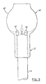
- Figure 7 is a side elevational view of yet another embodiment of a candle shade in accordance with the present invention; and
- Figure 8 is a side elevational view of the candle shade of Figure 5 in combination with a candle shade support.
-
- Turning now to Figures 1 to 4, a candle shade in accordance with the present invention is shown and is generally identified by
reference numeral 10. In the present embodiment,candle shade 10 is formed of glass although other suitable transparent, translucent and/or opaque materials may be used. As can be seen,candle shade 10 includes atubular sleeve 12 adapted to be placed on and receive the top end of acandle 14. Ashade element 16 sits on thesleeve 12 and surrounds thewick 14a of thecandle 14. -
Sleeve 12 includes acylindrical side wall 20 having anouter surface 22 and aninterior surface 24. An outwardly extendingflange 26 is formed adjacent the bottom end of thesleeve 12 and defines anannular support surface 28 on which theshade element 16 sits. An inwardly extendingflange 30 is formed at the top end of thesleeve 12 and defines acentral aperture 32 through which thewick 14a of thecandle 14 passes. Adepression 34 surrounding thewick 14a is formed in the top of theflange 30.Vertical ribs 36 are formed on theinterior surface 24 of thesleeve 12. Theribs 36 are equally spaced about the circumference of thesleeve 12 and act to space theinterior surface 24 of the sleeve from the body of thecandle 14. Thus, theribs 36 reduce the contact area between thesleeve 12 and thecandle 14. -
Shade element 16 in the present embodiment includes abowl 40 that terminates in a dependingsleeve 42.Sleeve 42 is sized so that its diameter is greater than the diameter of thesleeve 12 allowingsleeve 42 to slide freely oversleeve 12. The diameter of thesleeve 42 is however smaller than the outer diameter of theflange 26. Thus,sleeve 42 accommodates thesleeve 12 and rests on theannular support surface 28 thereby to position thebowl 40 above thecandle 14. -
Vents 44 are provided in thesleeve 42 at circumferentially spaced locations to permit air to be drawn into the bottom portion of thebowl 40 via the space between thesleeves wick 14a of thecandle 14 is lit. Thebowl 40 is shaped so that air drawn into thebowl 40 travels from the bottom to the top of the bowl in a smooth flow. The smooth air flow ensures sufficient air for the purpose of combustion and serves to cool thebowl 40 andsleeves - In use, the
sleeve 12 is placed on the top end of thecandle 14 so that theflange 30 rests on the top of the candle and thewick 14a of the candle is lit. Thus, theflange 30 acts as a stop to ensure thesleeve 12 remains at the top of thecandle 14. Thesleeve 42 is then placed over thesleeve 12 so that it rests on theannular support surface 28. In this manner, thebowl 40 surrounds the top of thecandle 14 to shade the burningwick 14a. As thecandle 14 melts, thesleeve 12 and theshade element 16 descend with the melting candle under the weight of theshade element 16. Melting wax from thecandle 14 is collected in thedepression 34 to inhibit the flow of wax into the channels defined betweenadjacent ribs 36. Since theribs 36 space theinterior surface 24 of thesleeve 12 from the body of thecandle 14, the contact area between thesleeve 12 and thecandle 14 is reduced. As a result, the coefficient of friction between thesleeve 12 and the candle body is reduced facilitating smooth and supported movement of thesleeve 12 and theshade element 16 downwardly with thecandle 14 as the candle melts. As mentioned previously, thevents 44 and the shape ofbowl 40 permit sufficient air flow into thebowl 40 to ensure good combustion and cooling. - Although the
ribs 36 formed on the interior surface of thesleeve 12 are shown as being vertically oriented, alternative rib configurations are possible. For example, the ribs may be circular and positioned on the interior surface of the sleeve at vertically spaced locations. This rib design is better suited for use with drip-less candles. Alternatively, the ribs may be helical. In this case, the shape of the ribs causes thesleeve 12 andshade element 16 to rotate as the candle melts and the sleeve and shade element descend with the melting candle. - If desired vents may also be provided in the
sleeve 12 and/or thebowl 40. If vents are provided in thesleeve 12, it is preferred that the vents are positioned so that the vents in thesleeves sleeve 42 accommodates thesleeve 12. - Also, although the
candle shade 10 is described as including asleeve 12 that is separate from theshade element 16, thesleeve 12 andshade element 16 can be integrally formed as shown in Figures 5 and 6. As can be seen, in this embodiment the sleeve 12' is integral with and depends from the bowl 40'. Ribs 36' are formed on the interior surface 24' of the sleeve 12' to space the interior surface of the sleeve 12' from the candle body. Vents 44' are formed in the bowl 40' at circumferentially spaced locations adjacent the flange 30' to permit air flow into the bowl when thewick 14a of thecandle 14 is lit. - Turning now to Figure 7, yet another embodiment of a
candle shade 110 in accordance with the present invention is shown. Similar to the previous embodiment, theshade element 116 andsleeve 112 are integrally formed.Vents 144 are formed in thebowl 140 at circumferentially spaced locations. In this embodiment, thesleeve 112 hasvertical slots 150 provided therein. Also, rather than using ribs to space the interior surface of the sleeve from the candle body,projections 152 are formed on the interior surface of thesleeve 112 at spaced locations. - As will be appreciated by those skilled in the art, the spacing elements to reduce the contact area between the interior of the sleeve and the candle body may take a variety of shapes provided the spacing elements permit the sleeve to descend with the candle as the candle melts.
- The candle shade may also be used in combination with a
candle shade support 200 as illustrated in Figure 8. As can be seen, thecandle shade support 200 is designed to support thecandle 14 and receive the bottom of thesleeve 112 when the sleeve descends with the melting candle. In this manner, thecandle shade 110 is supported by thecandle shade support 200 in an upright manner after the candle has burned down. - As will be appreciated, the present candle shade is designed to descend with the candle as the candle melts in a smooth and controlled manner while ensuring adequate air flow for combustion and cooling. The candle shade is aesthetically pleasing and may carry decorative accents.
- Although preferred embodiments of the present invention have been described, those of skill in the art will however appreciate that variations and modifications may be made without departing from the spirit and scope thereof as defined by the appended claims.
Claims (29)
- A candle shade comprising:a sleeve adapted to receive a top end of a candle, said sleeve having an interior surface, at least one spacing element on said interior surface to space said interior surface from the candle and a stop on said sleeve to inhibit said sleeve from travelling down the candle beyond the top end thereof; anda shade element coupled to said sleeve and surrounding said candle adjacent said top end.
- A candle shade according to claim 1 further including at least one vent to permit air flow into said shade element adjacent said top end.
- A candle shade according to claim 2 wherein said stop is an inwardly directed flange adjacent a top end of said sleeve, said flange resting on the top of said candle and defining an opening through which the wick of said candle passes.
- A candle shade according to claim 3 wherein said flange is annular and defines a circular aperture through which said wick passes.
- A candle shade according to claim 4 wherein said flange has a depression formed in an upper surface thereof, said depression surrounding said aperture.
- A candle shade according to claim 2 wherein said at least one spacing element is in the form of a plurality of ribs formed on said interior surface.
- A candle shade according to claim 6 wherein said ribs are vertical and are spaced about the circumference of said sleeve.
- A candle shade according to claim 6 wherein said ribs are circular and are disposed at vertically spaced locations along said sleeve.
- A candle shade according to claim 6 wherein said ribs are helical and extend between opposite ends of said sleeve.
- A candle shade according to claim 2 wherein said sleeve and said shade element are integrally formed.
- A candle shade according to claim 10 wherein said shade element includes a bowl and wherein said sleeve depends from said bowl.
- A candle shade according to claim 11 wherein said at least one vent is formed in said bowl adjacent said stop.
- A candle shade according to claim 12 wherein vents are provided in said bowl at circumferentially spaced locations.
- A candle shade according to claim 2 wherein said shade element includes a bowl and a second sleeve depending from said bowl, said second sleeve accommodating said first sleeve, and resting on a support surface formed on an outer surface of said first sleeve.
- A candle shade according to claim 14 wherein said first sleeve has an outwardly extending annular flange thereon adjacent a bottom end thereof, said outwardly extending flange defining said support surface.
- A candle shade according to claim 14 wherein said at least one vent is formed in at least one of said bowl and second sleeve.
- A candle shade according to claim 16 when said at least one vent is formed in said bowl adjacent said stop.
- A candle shade according to claim 17 wherein vents are provided in said bowl at circumferentially spaced locations.
- A candle shade according to claim 16 wherein said at least one vent is formed in said second sleeve.
- A candle shade according to claim 19 wherein vents are provided in said second sleeve at circumferentially spaced locations.
- A candle shade according to claim 2 wherein said bowl is shaped to provide smooth air flow therethrough during combustion when the wick of said candle is lit.
- A candle shade comprising:a sleeve adapted to receive a top end of a candle, said sleeve having an inwardly directed stop thereon to rest on the top of said candle and spacing elements on an interior surface thereof, said spacing elements contacting said candle to reduce contact area between said sleeve and said candle; anda shade element coupled said sleeve and surrounding said candle above said top end.
- A candle shade according to claim 22 wherein said stop is an inwardly directed flange having a depression formed in an upper surface thereof and defining an aperture through which the wick of said candle passes, said depression surrounding said aperture.
- A candle shade according to claim 22 wherein said spacing elements are vertical ribs disposed about the circumference of said sleeve.
- A candle shade according to claim 22 wherein said spacing elements are circular ribs disposed at vertically spaced locations along said sleeve.
- A candle shade according to claim 22 wherein said spacing elements are helical ribs extending between opposite ends of said sleeve.
- A candle shade according to claim 22 wherein said spacing elements are spaced projections formed on said interior surface.
- A candle shade according to claim 22 further comprising at least one vent provided in at least one of said sleeve and shade element.
- A candle shade according to claim 28 wherein vents are provided in said shade element at circumferentially spaced locations.
Applications Claiming Priority (2)
| Application Number | Priority Date | Filing Date | Title |
|---|---|---|---|
| US25248500P | 2000-11-22 | 2000-11-22 | |
| US252485P | 2000-11-22 |
Publications (2)
| Publication Number | Publication Date |
|---|---|
| EP1219891A2 true EP1219891A2 (en) | 2002-07-03 |
| EP1219891A3 EP1219891A3 (en) | 2004-06-30 |
Family
ID=22956203
Family Applications (1)
| Application Number | Title | Priority Date | Filing Date |
|---|---|---|---|
| EP01309842A Withdrawn EP1219891A3 (en) | 2000-11-22 | 2001-11-22 | Candle shade |
Country Status (3)
| Country | Link |
|---|---|
| US (1) | US6672742B2 (en) |
| EP (1) | EP1219891A3 (en) |
| CA (1) | CA2363436C (en) |
Cited By (2)
| Publication number | Priority date | Publication date | Assignee | Title |
|---|---|---|---|---|
| WO2005093026A2 (en) * | 2004-03-25 | 2005-10-06 | Michaela Yates | Candles, candle containers and methods of manufacture thereof |
| GB2457545A (en) * | 2008-02-23 | 2009-08-26 | Leonard Stanley Downing | Adjustable candle lantern with shades |
Families Citing this family (8)
| Publication number | Priority date | Publication date | Assignee | Title |
|---|---|---|---|---|
| US7350720B2 (en) * | 2004-02-03 | 2008-04-01 | S.C. Johnson & Son, Inc. | Active material emitting device |
| US7824627B2 (en) * | 2004-02-03 | 2010-11-02 | S.C. Johnson & Son, Inc. | Active material and light emitting device |
| EP1878449A1 (en) * | 2004-02-03 | 2008-01-16 | S.C.Johnson & Son, Inc | Device providing coordinated emission of light and volatile active |
| US20060120080A1 (en) * | 2004-02-03 | 2006-06-08 | Gene Sipinski | Control and an integrated circuit for a multisensory apparatus |
| US20060204915A1 (en) * | 2005-03-11 | 2006-09-14 | Metzler Hal W | Candle accessory |
| US7726860B2 (en) * | 2005-10-03 | 2010-06-01 | S.C. Johnson & Son, Inc. | Light apparatus |
| US20080315005A1 (en) * | 2007-06-25 | 2008-12-25 | Michaels Kenneth W | Active material emitting device and method of dispensing an active material |
| US11118762B1 (en) * | 2020-09-14 | 2021-09-14 | Shenzhen Yuytyuan Technology Co., Ltd | Lamp |
Citations (2)
| Publication number | Priority date | Publication date | Assignee | Title |
|---|---|---|---|---|
| US4755135A (en) | 1985-11-19 | 1988-07-05 | Kwok Wai Shi | Candle device |
| DE29621262U1 (en) | 1996-12-06 | 1997-02-06 | Shieh Jack | Candle holder |
Family Cites Families (11)
| Publication number | Priority date | Publication date | Assignee | Title |
|---|---|---|---|---|
| DE10787C (en) * | G. ROTHGIESSER in Hannover, Windmühlenstrafse 6 | Glass dome for candles, which lowers when the latter burns | ||
| US1255614A (en) * | 1917-10-17 | 1918-02-05 | Edward J Knapp | Sanctuary-lamp. |
| FR520317A (en) * | 1920-07-10 | 1921-06-23 | Hermann Schmid | Economical and protective burner for candles |
| US1562637A (en) * | 1925-04-28 | 1925-11-24 | Groth Norbert | Candle protector |
| US1890378A (en) * | 1931-08-19 | 1932-12-06 | John G Godoy | Lighting fixture |
| US2717306A (en) * | 1953-02-04 | 1955-09-06 | Bloomfield Ind Inc | Candle lamps |
| US3767910A (en) * | 1972-02-22 | 1973-10-23 | Harrigan R Major | Decorative structure |
| US3867625A (en) * | 1973-07-16 | 1975-02-18 | Charles C Whalen | Candle lamp |
| FR2715995A1 (en) | 1994-02-09 | 1995-08-11 | Point Ligne Ste Nouvelle | Non=flammable candle safety sleeve |
| US6328935B1 (en) * | 2000-07-06 | 2001-12-11 | Custom Essence, Inc. | Aroma dispenser for candle |
| US6457969B1 (en) * | 2000-08-09 | 2002-10-01 | United States Can Company | Candle tin |
-
2001
- 2001-11-21 US US09/989,987 patent/US6672742B2/en not_active Expired - Lifetime
- 2001-11-21 CA CA002363436A patent/CA2363436C/en not_active Expired - Fee Related
- 2001-11-22 EP EP01309842A patent/EP1219891A3/en not_active Withdrawn
Patent Citations (2)
| Publication number | Priority date | Publication date | Assignee | Title |
|---|---|---|---|---|
| US4755135A (en) | 1985-11-19 | 1988-07-05 | Kwok Wai Shi | Candle device |
| DE29621262U1 (en) | 1996-12-06 | 1997-02-06 | Shieh Jack | Candle holder |
Cited By (4)
| Publication number | Priority date | Publication date | Assignee | Title |
|---|---|---|---|---|
| WO2005093026A2 (en) * | 2004-03-25 | 2005-10-06 | Michaela Yates | Candles, candle containers and methods of manufacture thereof |
| WO2005093026A3 (en) * | 2004-03-25 | 2005-12-22 | Michaela Yates | Candles, candle containers and methods of manufacture thereof |
| GB2457545A (en) * | 2008-02-23 | 2009-08-26 | Leonard Stanley Downing | Adjustable candle lantern with shades |
| GB2457545B (en) * | 2008-02-23 | 2012-07-04 | Leonard Stanley Downing | Adjustable candle lantern with shades |
Also Published As
| Publication number | Publication date |
|---|---|
| CA2363436C (en) | 2008-01-15 |
| US20020105810A1 (en) | 2002-08-08 |
| EP1219891A3 (en) | 2004-06-30 |
| US6672742B2 (en) | 2004-01-06 |
| CA2363436A1 (en) | 2002-05-22 |
Similar Documents
| Publication | Publication Date | Title |
|---|---|---|
| US4526530A (en) | Burner for liquid candle | |
| CA2363436C (en) | Candle shade | |
| CA1217067A (en) | Wick holder for a liquid-fuel lamp | |
| US6398544B2 (en) | Formed safety bottom for a candle can | |
| US5840257A (en) | Device for use with an oil lamp to allow diffusion of the scent of a perfume | |
| US10316270B2 (en) | Burner cup | |
| US20020058223A1 (en) | Venting plate for a containerized candle | |
| US4805076A (en) | Liquid candle lamp with disposable fuel cell | |
| CN101715530A (en) | Candle burning device | |
| US4184195A (en) | Decorative candle lamp | |
| US4887960A (en) | Automatic flame snuffer assembly | |
| US5541824A (en) | Chimney assembly for illumination sources | |
| US5228771A (en) | Transparent table lamp | |
| EP3730157B1 (en) | Decorative combustion device capable of emitting fragrance | |
| US4399494A (en) | Decorative lamp | |
| CA2247751A1 (en) | A multiple candle lantern | |
| US2060324A (en) | Sanctuary candle lamp | |
| CA2208145A1 (en) | Device for use with an oil lamp to allow diffusion of the scent of a perfume | |
| US5879152A (en) | Socketless drip preventing candle holder | |
| WO2000037848A1 (en) | Candle holders and followers for drip prevention, fragrance dispensing and auxiliary illumination | |
| US6264345B1 (en) | Drip preventing candle holder with decorative follower providing auxiliary illumination | |
| JPS58158427A (en) | Automatic fire extinguishing mechanism | |
| GB2067739A (en) | A device for obtaining the dripless burning of a candle | |
| KR200329812Y1 (en) | candle case with a windbreak | |
| JP3037985U (en) | Light fixture |
Legal Events
| Date | Code | Title | Description |
|---|---|---|---|
| PUAI | Public reference made under article 153(3) epc to a published international application that has entered the european phase |
Free format text: ORIGINAL CODE: 0009012 |
|
| AK | Designated contracting states |
Kind code of ref document: A2 Designated state(s): AT BE CH CY DE DK ES FI FR GB GR IE IT LI LU MC NL PT SE TR |
|
| AX | Request for extension of the european patent |
Free format text: AL;LT;LV;MK;RO;SI |
|
| PUAL | Search report despatched |
Free format text: ORIGINAL CODE: 0009013 |
|
| AK | Designated contracting states |
Kind code of ref document: A3 Designated state(s): AT BE CH CY DE DK ES FI FR GB GR IE IT LI LU MC NL PT SE TR |
|
| AX | Request for extension of the european patent |
Extension state: AL LT LV MK RO SI |
|
| RIC1 | Information provided on ipc code assigned before grant |
Ipc: 7F 21V 17/04 B Ipc: 7F 21V 35/00 A |
|
| AKX | Designation fees paid | ||
| REG | Reference to a national code |
Ref country code: DE Ref legal event code: 8566 |
|
| STAA | Information on the status of an ep patent application or granted ep patent |
Free format text: STATUS: THE APPLICATION IS DEEMED TO BE WITHDRAWN |
|
| 18D | Application deemed to be withdrawn |
Effective date: 20041231 |