EP1216796A1 - Apparatus for robotically inspecting gas turbine combustion components - Google Patents
Apparatus for robotically inspecting gas turbine combustion components Download PDFInfo
- Publication number
- EP1216796A1 EP1216796A1 EP01310454A EP01310454A EP1216796A1 EP 1216796 A1 EP1216796 A1 EP 1216796A1 EP 01310454 A EP01310454 A EP 01310454A EP 01310454 A EP01310454 A EP 01310454A EP 1216796 A1 EP1216796 A1 EP 1216796A1
- Authority
- EP
- European Patent Office
- Prior art keywords
- arm
- inspection head
- inspection
- transition piece
- axis
- Prior art date
- Legal status (The legal status is an assumption and is not a legal conclusion. Google has not performed a legal analysis and makes no representation as to the accuracy of the status listed.)
- Withdrawn
Links
Images


Classifications
-
- F—MECHANICAL ENGINEERING; LIGHTING; HEATING; WEAPONS; BLASTING
- F02—COMBUSTION ENGINES; HOT-GAS OR COMBUSTION-PRODUCT ENGINE PLANTS
- F02C—GAS-TURBINE PLANTS; AIR INTAKES FOR JET-PROPULSION PLANTS; CONTROLLING FUEL SUPPLY IN AIR-BREATHING JET-PROPULSION PLANTS
- F02C7/00—Features, components parts, details or accessories, not provided for in, or of interest apart form groups F02C1/00 - F02C6/00; Air intakes for jet-propulsion plants
-
- B—PERFORMING OPERATIONS; TRANSPORTING
- B25—HAND TOOLS; PORTABLE POWER-DRIVEN TOOLS; MANIPULATORS
- B25J—MANIPULATORS; CHAMBERS PROVIDED WITH MANIPULATION DEVICES
- B25J5/00—Manipulators mounted on wheels or on carriages
-
- B—PERFORMING OPERATIONS; TRANSPORTING
- B25—HAND TOOLS; PORTABLE POWER-DRIVEN TOOLS; MANIPULATORS
- B25J—MANIPULATORS; CHAMBERS PROVIDED WITH MANIPULATION DEVICES
- B25J5/00—Manipulators mounted on wheels or on carriages
- B25J5/02—Manipulators mounted on wheels or on carriages travelling along a guideway
-
- F—MECHANICAL ENGINEERING; LIGHTING; HEATING; WEAPONS; BLASTING
- F01—MACHINES OR ENGINES IN GENERAL; ENGINE PLANTS IN GENERAL; STEAM ENGINES
- F01D—NON-POSITIVE DISPLACEMENT MACHINES OR ENGINES, e.g. STEAM TURBINES
- F01D25/00—Component parts, details, or accessories, not provided for in, or of interest apart from, other groups
- F01D25/28—Supporting or mounting arrangements, e.g. for turbine casing
- F01D25/285—Temporary support structures, e.g. for testing, assembling, installing, repairing; Assembly methods using such structures
Definitions
- the present invention relates to a robotic inspection system for in situ inspection of gas turbine cannular combustion components for the purpose of evaluating the condition of the components.
- Maintenance costs and equipment availability are two of the most important concerns of a gas turbine operator. Proper maintenance is required to minimize equipment downtime and provide long-term reliable operation. Maintenance inspections of gas turbines are broadly classified as standby, running and disassembly. Disassembly inspections are generally categorized into three types: combustion inspection, hot gas path inspection and major inspection. All three types of inspections require shutdown and disassembly of the turbine to varying degrees to enable inspection and replacement of aged and worn components.
- the combustion inspection includes evaluation of several components of the combustion system including the transition piece.
- the transition piece is a thin-walled duct used to conduct high-temperature combustion gases from the combustion chamber to the annular turbine nozzle passage.
- transition piece and other combustion components are generally inspected for foreign objects, abnormal wear, cracking, thermal barrier coating TBC condition, oxidation/corrosion/erosion, hot spots/burning, missing hardware and clearance limits. Components which fall outside established threshold limits are replaced to maintain optimum operating conditions for the entire system. If not rectified, these conditions could lead to reduced machine efficiency and damage to the turbine that may result in unplanned outages and significant repair costs.
- transition pieces Removal and installation of transition pieces is the most time-intensive operation of the combustion inspection. This operation contributes most significantly to the combustion inspection outage duration and corresponds directly to time lost producing power.
- To remove transition pieces all upstream components must be removed, i.e., fuel nozzles, water injectors and various other hardware. Each transition piece is then dismounted and removed one by one in sequence through two access openings in the turbine casing. It will be appreciated that for certain gas turbines, there can be as many as fourteen transition pieces requiring removal.
- a robotic inspection system for gas turbine combustion components comprised of three robotic manipulators with miniature cameras and lighting for inspecting various parts of the transition piece of each combustor in situ.
- the manipulators are driven remotely using a combination of automated and manual motion control to position the inspection heads, e.g., video cameras, lighting and/or measuring devices, to various locations about and in the combustor enabling a detailed visual inspection of its transition piece and flow sleeve without disassembly and removal of these components from the turbine.
- the robotic inspection system hereof is thus intended for use during a gas turbine maintenance outage.
- the robotic inspection system hereof includes three tools, i.e., an exterior manipulator, an interior manipulator and an annulus manipulator.
- the transition piece includes an outer impingement sleeve, typically perforated, and an interior transition piece body defining generally an annulus therebetween.
- the forward ends of the transition piece body and impingement sleeve are generally circular in configuration with top and bottom sides being flattened progressively toward the first-stage nozzle.
- the exterior manipulator is deployed for inspection of the external surfaces of the impingement sleeve and has seven distinct motions.
- the exterior manipulator includes a segmented arcuate rail movably mounted on a carriage disposed within the casing of the turbine, the carriage being supported externally of the casing by a mast.
- the rail extends in excess of 90° such that an inspection head forming part of a robotic inspection subassembly carried on an end segment can inspect top, bottom and side surfaces and along the entire length of each impingement sleeve in a quadrant of the annularly arranged combustors.
- the robotic inspection subassembly on the end segment mounts a generally axially extending rail on which is mounted an upper arm.
- the rail is movable in a circumferential direction with the arcuate segments as the latter are displaced circumferentially along the carriage to locations radially outwardly of the impingement sleeves and within the interior surface of the casing.
- the upper arm is pivotable relative to the rail about a first axis to extend between adjacent impingement sleeves and carries at its distal end a pivotally mounted forearm.
- the upper arm is also rotatable about its long axis such that when the forearm is extended, the inspection head carried at the distal end of the forearm can be located between and radially inwardly of an impingement sleeve for inspection of its radial inner surface.
- the inspection head is rotatable about pan and tilt axes relative to the forearm and includes a vision module, e.g., one or more cameras and a lighting system. With this arrangement, the inspection head can be located to inspect the entire peripheral surface of each impingement sleeve of the cannular combustion system.
- a video micrometer external to the tool may be used in conjunction with the vision module to effect measurements.
- the interior manipulator is mounted to the aft combustion casing for inspecting the interior surface of the transition piece body.
- the interior manipulator includes an elongated arm carried in a spherical bearing in a mount secured to the casing flange.
- the interior end of the arm carries an inspection head similar to that of the exterior manipulator.
- the arm projects through the mount exteriorly of the casing and is pivoted by two linear actuators coupled between the mount and the arm to locate the inspection head adjacent the interior surface of the transition piece body.
- the arm also carries concentric inner and outer tubes. Actuation of an electric motor carried by the outer tube extends and retracts the inner tube carrying the inspection head.
- the inner tube carries pan and tilt motors such that the inspection head can be rotated about pan and tilt axes for visual inspection of the interior surfaces of the transition piece body.
- the annulus manipulator includes a manually positioned inspection head for inspecting the side seam welds along the exterior surface of the transition piece body in the annulus between the transition piece body and the impingement sleeve.
- the annulus manipulator includes a support structure for supporting a pair of spaced guide plates each having a pair of contoured surfaces, e.g., grooves in opposition to one another. The grooves generally correspond to the contours of the side seam welds of the transition piece body.
- a middle carriage plate carries sets of pins on opposite sides thereof engaging in the grooves and is movable longitudinally along the guide plates. The middle carriage plate also carries side carriage plates for movement along respective laterally facing external surfaces of the guide plates.
- Each side carriage plate carries a holder for a wand tube which carries the inspection head.
- the side carriage plates With the annulus manipulator located within the casing and the wand tube secured to one of the wand carriers, the side carriage plates are advanced toward the transition piece body by manually advancing the wand tube. As the side carriage plates are advanced, they follow the contour of the grooves which enables the inspection head to follow the contour of a side seam weld.
- the inspection head can be located directly adjacent a side seam weld of the transition piece body and displaced lengthwise along the transition piece body thereby following and registering with the contour of the weld.
- the cameras for the inspection heads can be remotely and dynamically focused from a remote control station.
- motorized cam assemblies are utilized that move the camera lens.
- a video micrometer subsystem is used to quantitatively dimension features appearing in the video imagery. For example, a pair of laser lights at a fixed distance apart are incorporated into the inspection head of the interior robotic manipulator. The lasers provide a known size feature used to calibrate the video micrometer for any camera field of view. A similar process may be used for the exterior manipulator, although known size features of the transition piece body are used as the calibration reference rather than lasers.
- apparatus for in situ inspection of the exterior surface of an impingement sleeve of one of a plurality of an annular array of combustors for a gas turbine wherein the turbine has an outer casing about an axis of rotation of a turbine rotor and at least one opening through the casing for access to the impingement sleeve comprising a manipulator having an arcuate segment and a carriage for supporting the segment within the casing for movement in a circumferential direction about the annular array of combustors, a rail carried by the segment, a first arm carried by the rail for translatory movement therealong and pivotal movement relative to the rail about a first axis generally normal to the axis of rotation of the rotor, a second arm coupled at one end to the first arm for pivotal movement about a second axis normal to a plane containing the first arm and the second arm and an inspection head carried by the second arm adjacent an opposite end thereof for pivotal movement about pan and
- apparatus for inspecting in situ an interior of a transition piece body of one of a plurality of annular array of combustors for a gas turbines comprising a mount for mounting to an open end of a turbine casing forwardly of the transition piece body, an inspection arm carried by the mount intermediate opposite ends thereof for pivotal movement relative to the mount, an inspection head carried by the arm adjacent one end thereof, a pair of actuators coupled to the mount and the arm adjacent an opposite end thereof for pivoting the arm relative to the mount to locate the inspection head in registration with selected portions of the interior wall surface of the transition piece body, the arm including a pair of telescopically related members, a drive mechanism for extending one member relative to the other member, the one member carrying the inspection head.
- apparatus for inspecting in situ side seam welds along a transition piece body spaced inwardly of an impingement sleeve of a combustor in a combustion system for a gas turbine comprising an elongated guide having a contoured surface generally corresponding to the contour of the side seam weld of the transition piece body, a mount for fixing the guide to the combustor, a cam follower for following the contoured surface upon displacement of the cam follower along the guide, an inspection head carried by the cam follower and means for displacing the inspection head longitudinally along the space between the impingement sleeve and the transition piece body so that the inspection head tracks the contoured surface of the guide whereby the inspection head is maintained during its longitudinal displacement in registration with the side seam weld of the transition piece body.
- FIG. 1 there is schematically illustrated an axial view of a gas turbine, generally designated 10, having an outer casing 12 and an annular array of combustors including combustion flow sleeves 14 within the casing 12.
- the rotational axis of the gas turbine rotor, not shown, is indicated at 16.
- an access opening or manhole 18 through which an external manipulator, generally designated 20, is inserted for inspecting the external surface of each of the impingement sleeves of the transition pieces.
- an inspection head 22 may be displaced axially the full length of the impingement sleeve as well as positioned at any location about the entire external peripheral surface of the impingement sleeve.
- FIG. 2 there is illustrated a flow sleeve 14 and a transition piece 24, the transition piece including an impingement, i.e., perforated sleeve 26 surrounding a transition piece body 28.
- Body 28 extends generally axially from adjacent the forward end of the impingement sleeve 26 and is connected at its rearward end to the first-stage nozzle, not shown, of the gas turbine for flowing hot gases of combustion into the first-stage nozzle.
- the impingement sleeve 26 and transition piece body 28 are generally circular at their forward ends and flatten out toward their rearward ends, terminating in a generally rectilinear opening for flowing the gases into the first-stage nozzle.
- the combustion system component and more particularly the transition piece inspection system of the present invention includes three inspection tools, namely: an exterior manipulator, an interior manipulator and an annulus tool.
- the exterior manipulator is designed to inspect the external surface of the impingement sleeve 26 for damage to the zipper welds, aft brackets and bullhorns.
- the interior manipulator is designed to inspect the inside surface of the transition piece body 28 for cracking, corrosion and the like and particularly for ensuring that the thermal barrier coating is intact.
- the annulus tool inspects the exterior surface of the side seam welds 29 securing upper and lower halves of the transition piece body to one another.
- manipulator 20 is inserted in sections through the access opening 18 and includes a support carriage 32 connected to a mast 34 secured externally of casing 12 to support the manipulator 20 within the casing 12.
- the carriage 32 supports a plurality of arcuate segments 36 connected one to the other and which segments extend along an arc in excess of 90° in a plane perpendicular to the rotor axis 16. It will be appreciated that access openings 18 are provided at locations 180° apart about casing 12.
- each of the impingement sleeves can be inspected by the inspection head in each quadrant about axis 16 adjacent an access opening 18.
- the distal end of the arcuate segments 36 carries a robotic inspection system subassembly, generally designated 39 ( Figure 6), including a rail 38 which extends in a general axial direction relative to the turbine rotor axis 16. Rail 38, in turn, carries a slider 40 ( Figure 10) mounting a shoulder gearbox 42 ( Figures 11 and 12).
- first arm 44 Projecting from gearbox 42 is an upper or first arm 44 (Figure 13) pivotally carrying a second arm, i.e., a forearm 46.
- inspection head 48 mounted for movement axially relative to forearm 46 and in pan and tilt directions.
- the rotational axis of the gas turbine is indicated 16 in Figure 3.
- the arcuate segments 36 lie in a plane perpendicular to axis 16.
- the rail 38 extends generally parallel to axis 16 and moves with the arcuate segments 36 in a circumferential direction about axis 16 as indicated by the double-ended arrow 50.
- the shoulder gearbox 42 mounted on slider 40 moves with slider 40 in a generally axial direction along the rail 38, generally parallel to axis 16, thus displacing the upper arm 44, forearm 46 and inspection head 48 in a forward and aft direction generally parallel to axis 16.
- gearbox 42 This linear movement of gearbox 42 is indicated by the double-ended arrow 52 in Figure 3.
- the shoulder gearbox 42 also causes rotation of the upper arm 44, forearm 46 and the inspection head 48 carried at the distal end of forearm 46 about a generally tangential first axis 53, the rotary motion about first axis 53 being indicated by the arcuate double-ended arrow 54.
- Gearbox 42 also rotates the upper arm 44 about its long axis 45 and which rotational movement about rotational axis 45 is indicated by the arcuate double-ended arrow 56.
- Forearm 46 is pivotally mounted to the distal end of upper arm 44 for rotation about a second axis 57 extending through the elbow joint between the upper arm 44 and the forearm 46 and perpendicular to a plane containing upper arm 44 and forearm 46.
- the rotational direction is illustrated by the arcuate double-ended arrow 58 about axis 57 in Figure 3. It will be appreciated that axes 53 and 57 are also parallel to one another.
- Inspection head 48 mounted on the distal end of forearm 46 is rotatable in pan and tilt directions. That is, inspection head 48 is rotatable about the axis 59 of forearm 46 in pan and which rotation about axis 59 is indicated by the arcuate double-ended arrow 60.
- Inspection head 48 is also rotatable in tilt about an axis 61 perpendicular to the axis 59 of forearm 46 and which rotation about axis 61 is indicated by the arcuate double-ended arrow 62. Consequently, it will be appreciated that the inspection head 48 has seven degrees of freedom of movement.
- the mast 34 ( Figure 6) is supported externally of casing 12 and is preferably fixed to the casing.
- the carriage 32 is disposed within the casing 12 and supported by mast 34.
- support carriage 32 includes spaced mounting plates 70 and a gear carriage 72 between plates 70.
- Gear carriage 72 includes a centrally located spur gear 74 driven by the shaft 76 of an electric motor 78 carried within a housing 80 secured to the support carriage 32.
- Plates 70 also carry rollers 82 at opposite ends of the carriage 32 for supporting the arcuate segments 36, as well as side rollers 84 affording lateral support for the segments.
- each arcuate segment is in the form of an I-beam 86 and includes a rack gear 88 along an upper surface of the segment. It will be appreciated that the engagement between motor-driven gear 74 carried by the gear carriage 72 and rack 88 drives the arcuate segment 36 along the carriage 32.
- the gear carriage 72 is pivoted at one end about a pin 92.
- a spring-biased shaft 94 biases the opposite end of the gear carriage 72 such that the gear 74 is biased into engagement with the rack gear 88.
- Carriage 32 also includes a pair of cable guide wheels ( Figure 7) 90 for guiding electrical cables, not shown, along the arcuate segments 36 for controlling the various motors of the external manipulator.
- each female dovetail 83 may receive the male dovetail 85 of an adjoining segment such that the segments can be assembled within the casing 12.
- the distal end of the first inserted segment carries the robotic subassembly 39 including rail 38, shoulder gearbox 42, upper arm 44, forearm 46 and inspection tool 48.
- a pin connection is provided to secure the distal segment and the rail 38 to one another such that the rail 38 extends from the arcuate segment in a general axial direction (see Figures 3-5) and to opposite axial sides of the distal segment.
- the pin connection is illustrated in Figure 10 by the female recess 96 and pin 97 coupled to a support 99 secured to rail 38 intermediate opposite ends of the rail.
- a gearbox 98 having a drive gear 100, an idler gear 101, and a driven gear 102.
- Gear 100 is driven directly by an electric motor 104 carried by rail 38.
- Drive gear 100 drives driven gear 102 through the idler gear 101.
- Mounted on gear 102 is a lead screw 108 extending the length of rail 38.
- a nut, not shown, fixed to the slider 40, is threaded about the lead screw 108.
- the slider 40 is mounted on rail 38 by rollers whereby the slider 40 traverses the length of rail 38 upon rotation of the lead screw 108.
- the shaft 120 of the shoulder gearbox 42 is keyed and secured to the slider 40 at the projecting end 121, i.e., the shaft 120 does not rotate relative to slider 40. Consequently, the shaft 120 and shoulder gearbox 42 translate with slider 40 linearly along the rail 38 upon rotation of lead screw 108.
- the gearbox 42 rotates about shaft 120.
- a gear 122 is rigidly mounted on the shaft 120, i.e., the shaft 120, gear 122 and slider 40 are rigidly connected with one another.
- a motor 124 is mounted on gearbox 42 and drives a gear 126 in engagement with gear 122. Since gear 122 is fixed to shaft 120, actuation of drive motor 124 rotates gears 126 and 122, causing the gearbox 42 to rotate about shaft 120, i.e., first axis 53 ( Figure 3).
- the shoulder gearbox includes a motor 150 (Figure 11) for rotating the upper arm 44.
- the upper arm 44 is mounted on a bearing 152 surrounding a fixed stub shaft 154 coupled to the housing of the gear box 42.
- a thrust bearing 156 carries the upper arm 44 for rotation.
- a gear 158 is connected to the outer tube 160 of the upper arm 44 and engages a gear 162 on the shaft 164 of motor 150. Consequently, by actuating motor 150 in either direction, the gear drive rotates the upper arm 44 about its own axis, i.e., rotational axis 45 ( Figures 3 and 11).
- the forearm 46 is secured to the distal end of the upper arm 44 for pivotal movement about the second axis 57 ( Figures 13 and 3).
- upper arm 44 carries a bearing sleeve 180 ( Figure 13) surrounded by a bushing 182 carried by the forearm 46.
- a drive pulley 184 is carried on the bushing 182 and cables 186 are wrapped about pulley 184 for pivoting the forearm 46 about axis 57 and relative to the upper arm 44.
- cables 186 are wrapped about a cable drum 187 ( Figures 11 and 12) and extend past idler rolls 185 (Figure 11), through an interior guide tube 188, about idler rolls 189 and about drive pulley 184.
- a drive motor 191 (indicated by the dashed lines in Figure 12) is mounted to gearbox 42 and has a drive shaft 193 carrying a gear 195.
- Gear 195 engages a gear 197 mounted for rotation on shaft 120.
- Gear 197 is coupled to cable drum 187.
- the forearm 46 preferably includes an outer tube 190 ( Figure 13) to which is fixed a pan motor 192 internally within tube 190.
- the shaft 194 driven by motor 192 is connected to the proximal end of an interior rotatable tube 196 concentric within outer tube 190.
- the distal end of tube 196 is connected to the inspection head 48.
- actuation of motor 192 rotates inspection head 48 about the long axis of forearm 46, i.e., about a pan axis 59 ( Figures 3 and 13).
- a tilt drive motor 198 which drives a shaft 200, in turn coupled to a bevel gear 202.
- the shaft 200 is mounted in a bearing 204, the outer race of which is carried by inner tube 196.
- Bevel gear 202 lies in meshing engagement with a driven bevel gear 204 mounted on a tilt axis shaft 206, suitable bearings being provided for the shaft 206.
- Actuation of motor 198 thus rotates inspection head 48 about the axis of shaft 206, i.e., about tilt axis 61 ( Figures 3 and 13).
- the inspection head 48 includes various instruments such as a camera 208 and a light assembly 210, both mounted on the shaft 206. Consequently, actuation of tilt motor 198 rotates the camera and light assembly about the tilt axis to the desired positions.
- the exterior manipulator carriage 32 is disposed in the access opening 18 of the gas turbine and secured by securing the mast 34 to the casing 12.
- the first arcuate segment carrying the rail 38, gearbox 42, upper arm 44, forearm 46 and head 48 is inserted through the access opening and along carriage 32.
- the carriage 32 supports the assembly within the casing 12.
- the remaining arcuate segments 36 are connected to one another end-to-end by the dovetail connections and passed through carriage 32.
- the inspection head 48 can be advanced about a quadrant of the combustion casing and in a circumferential direction by actuation of motor 78 until it lies adjacent the impingement sleeve sought to be inspected. That is, the subassembly 39 is advanced in a circumferential direction in the radial space between the impingement sleeve 26 and the interior of casing 12 until it lies adjacent the impingement sleeve to be inspected.
- the upper arm 44 can be rotated and forearm 46 displaced from its folded position against upper arm 44 into positions to locate the inspection head 48 adjacent the area of the transition piece, i.e., impingement sleeve 26, to be inspected.
- the drive motor 124 in the shoulder gearbox 42 is energized to rotate the shoulder gearbox 42 about shaft 120, i.e., axis 53.
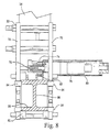
- the cable drum 126 is rotated by actuation of the motor 191 to pivot the forearm 46 relative to the upper arm 44 about axis 57 into the position illustrated in Figure 5.
- Motor 104 is also actuated and displaces the shoulder gearbox 42 linearly along the rail 38.
- the axial position of the inspection head 48 in relation to the area desired to be inspected is obtained.
- the shoulder gearbox 42 is rotated about axis 53 to locate the elbow, i.e., the joint between upper arm 44 and forearm 46 below, i.e., radially inwardly of, the impingement sleeve.
- Motor 191 is also actuated to rotate the forearm 46 about axis 57 to locate it below, i.e., radially inwardly of the impingement sleeve.
- Motor 150 is also actuated to rotate the upper arm 44 about its own axis 45, thus causing the forearm 46 to swing about the axis of upper arm 44 and below the impingement sleeve.
- the camera and light assembly can be focused on the area sought to be inspected.
- the various motors and positioning the exterior manipulator on opposite sides of the selected impingement sleeve the entirety of the exterior surface of each of the impingement sleeves for each combustor can be visually inspected and measurements taken in situ.
- the motors are all electrically driven remotely from outside the turbine casing through suitable electrical connections therewith. The motors can be actuated manually but are preferably computer controlled.
- the interior manipulator 200 includes a mount 202 at one end of the tool and an inspection head 204 at the opposite end of the tool carrying, for example, a similar camera and light assembly as the exterior manipulator.
- the mount 202 is in the form of a cross ( Figure 16) having legs 206 90° from one another. The legs 206 are mounted to the flanges of the combustion casing to secure the interior manipulator thereto.
- the central portion 208 of the mount 202 includes a spherical bearing 210 carried on a tubular section 212 projecting outwardly of the mount 202.
- On the inside of the mount 202 and carried by the tubular section 212 is an outer tube 214 for carrying the inspection head 204.
- a pair of linear actuators 220 are coupled between the outer ends of a pair of legs 206, respectively, and the outer end of the tubular section 212.
- each linear actuator 220 is pivotally secured to a clevis 222 mounted to the outer end of a leg 206.
- the actuator 220 includes a motor 224 which drives a lead screw 226 engaged in a threaded nut 228 mounted on a hinge 230.
- the hinge 230 is, in turn, mounted on the tubular section 212.
- the inspection head can be located adjacent any interior surface portion of the transition piece body 28.
- a motor 232 is carried by the tubular section 212. Motor 232 drives a lead screw 234 via a shaft coupling 236. A lead screw nut 238 is secured to an inner tube 240 concentric with outer tube 214. By actuating motor 232 and rotating lead screw 234 in engagement with nut 238, tube 240, which mounts the inspection head 204, can be advanced and retracted in an axial direction.
- a pan motor 242 drives a shaft 244, in turn coupled to a tube 246 carrying the inspection head 204.
- tube 246 and head 204 are rotated about the axis of the outer tube 214.
- a tilt motor 250 is provided and drives the inspection head about axis 248 through a shaft and beveled gear connection 250 and 252, respectively, similarly as previously described with respect to the exterior manipulator.
- the section 212 and tubes, i.e., members 214, 240 and 246 are collectively called the inspection arm.
- the operation of the interior manipulator is believed self-evident from the foregoing description.
- actuation of the linear motors 224 and 232 locate the inspection head 204 closely adjacent to a selected interior surface portion of the transition piece body sought to be inspected.
- motors 242 and 250 By actuating motors 242 and 250, the inspection head is rotated about pan and tilt axes and directed such that the light assembly illuminates the surface portion to be inspected by the video camera of head 204.
- the inspection head which preferably carries a camera and a light assembly similar to the previously described inspection heads is positioned in the annulus 30 between the transition piece body 28 and the impingement sleeve 26.
- the annulus manipulator is specifically configured to inspect the side seam weld 29 along opposite sides of the transition piece body.
- the transition piece body 28 is fabricated in upper and lower halves, with the halves being welded together along weld lines 29 which essentially follow the contour of the shaped upper and lower exterior surfaces of the transition piece body 28.
- the annulus manipulator 300 includes a pair of mounting plates 302 which are secured by bolts during inspection to the flanges of the combustor casing. Between the mounting legs 302, there is provided a pair of spaced V-rails 304. Extending centrally between the rails 304 is a lead screw 306, terminating at one end in a manually rotatable knob 308 supported by one of the mounting plates 302. The opposite end of the lead screw 306 is journalled into the opposing mounting plate 302. Lead screw 306 extends through a lead nut block 310, secured between and to a pair of spaced guide plates 314.
- the guide plates 314 are secured to one another by suitable spacers at longitudinally located positions along the lengths of the plates and serve as a guide for guiding an inspection head 347 along the side seam weld 29. Additionally, rollers 316 are provided on the outside of the guide plates 314 for bearing against the rails 304 to maintain the plates 314 in extended positions from the mounting plates 302 as illustrated in Figure 18. By operation of the knob 308, the guide plates 314 can be displaced accurately toward and away from opposite sides of the transition piece upon insertion of the annulus manipulator into the transition piece.
- each of the guide plates 314 includes a pair of longitudinally extending contoured surfaces, i.e., grooves 320 and 322.
- the grooves of each plate 314 register with corresponding grooves of the opposite plate.
- a middle carriage plate 324 Disposed between the guide plates 314 is a middle carriage plate 324 which carries a pair of guide pins 326 projecting from each of its opposite sides and engaging in the grooves 320 and 322, respectively. It will be appreciated that the middle carriage plate 324 is slidable lengthwise along the spaced guide plates 314 and along the grooves 320 and 322 of the guide plates 314, the middle carriage plate 324 serving as a cam follower with respect to the contoured surfaces 320 and 322.
- middle carriage plate 324 mount transversely extending end carriage plates 328.
- side carriage plates 330 ( Figure 19) which extend between the outer edges of the end carriage plates 328.
- the middle carriage plate 324 and end carriage plates 328 form essentially an I-beam with the side carriage plates 330 extending parallel to the middle carriage plate 324 and between end edges of the end carriage plates 328 along outside surfaces of the guide plates 314.
- each side carriage plate 330 mounts a pair of bearings 336 through which a lead screw 338 is rotatable.
- Lead screw 338 is rotatable on a nut 340 pivotally carried on the upper end of arm 332.
- Nut 340 is also movable vertically relative to its mounting 341 on arm 332. By rotating the lead screw, the nut 340 causes the arm 332 to pivot about pin 334 to provide a finite adjustable angular movement of the inspection head, as described below.
- each side carriage plate 330 On each side of each side carriage plate 330, there is provided a mounting block 344 ( Figures 17 and 19).
- a wand holder 346 is pinned to one of the mounting blocks 344.
- the lateral outer end of the wand holder 346 is adapted to receive a wand tube 348, illustrated in Figure 20, on the end of which is mounted an inspection head 347.
- Head 347 includes a light assembly 349 and a video camera 351.
- a carriage handle 348 is coupled by a universal joint 350 with the lead screw 338, the handle 348 extending the length of the annulus manipulator for manipulation externally thereof.
- the arm 332 carrying the wand tube 348 in the wand holder 346 can be pivoted to finitely locate the inspection head 347 along the weld seam 29.
- the mount 302 is secured to the flange of the combustion casing, with the middle and side carriage plates 324 and 330, respectively, extending into the transition piece, terminating short of the transition piece body 28.
- the wand tube 353 with the inspection head 347 is mounted to the wand holder 346 extends the length of the annulus manipulator.
- the middle and side carriage plates are jointly advanced along the guide plates 314 by pushing on the carriage handle 348. The inspection head 347 is thus guided into the space between the transition piece body 28 and the impingement sleeve 26.
- the side carriage plates 330 are guided by the movement of the middle carriage plate 324 along the grooves 320 and 322 to follow the contour of the side seam weld 29.
- the inspection head With the inspection head mounted on one of the side carriage plates 330, the inspection head likewise follows the contour of the side seam weld 29.
- the video camera and light assembly forming part of inspection head 347 thus register with the side weld 29 and record the integrity of the side seam weld.
- the angle of the camera 351 and light assembly 349 can be finitely adjusted within the annulus to view appropriate areas on either side of the weld seam and/or to ensure registration of the camera and light assembly with the weld.
- the annulus manipulator is retracted and the wand carrying the inspection head 347 is secured to the mounting block 344 carried by the other side carriage plate 330.
- the plates 324 and 330 are then advanced following the contours of the grooves 320 and 322 whereby the inspection head traverses along and inspects the opposite side weld seam.
Abstract
A robotic inspection system for gas turbine combustion components includes
an exterior manipulator (20) for visual inspection of the exterior surface of the
impingement sleeve, an interior manipulator (200) for visual inspection of the
interior of the transition piece body and an annulus manipulator (300) for
inspecting the side weld seams of the transition piece body. The exterior
manipulator includes an arcuate segment (36) extending about the annular
spaced impingement sleeves and a robotic subassembly including a linear rail
(38) and an upper arm (44) and forearm (46) mounting an inspection head
(48) pivotally coupled to one another for visual inspection of the top, bottom
and side external surfaces of the impingement sleeve. The interior
manipulator mounts to the open end of the combustion casing and includes
an arm (212, 214) mounted for universal pivotal movement to the mount,
actuators (224) for pivoting the arm and motors for extending and rotating an
inspection head about pan and tilt axes within the interior of the transition
piece body. The annulus manipulator includes a guide plate (314) mounted
to the combustor casing and having contoured surfaces (320, 322) tracking
the side weld seams. A carriage (324) mounts an inspection head and tracks
along the contoured surfaces to track along the seam, affording remote visual
inspection thereof.
Description
- The present invention relates to a robotic inspection system for in situ inspection of gas turbine cannular combustion components for the purpose of evaluating the condition of the components.
- Maintenance costs and equipment availability are two of the most important concerns of a gas turbine operator. Proper maintenance is required to minimize equipment downtime and provide long-term reliable operation. Maintenance inspections of gas turbines are broadly classified as standby, running and disassembly. Disassembly inspections are generally categorized into three types: combustion inspection, hot gas path inspection and major inspection. All three types of inspections require shutdown and disassembly of the turbine to varying degrees to enable inspection and replacement of aged and worn components. The combustion inspection includes evaluation of several components of the combustion system including the transition piece. The transition piece is a thin-walled duct used to conduct high-temperature combustion gases from the combustion chamber to the annular turbine nozzle passage. The transition piece and other combustion components are generally inspected for foreign objects, abnormal wear, cracking, thermal barrier coating TBC condition, oxidation/corrosion/erosion, hot spots/burning, missing hardware and clearance limits. Components which fall outside established threshold limits are replaced to maintain optimum operating conditions for the entire system. If not rectified, these conditions could lead to reduced machine efficiency and damage to the turbine that may result in unplanned outages and significant repair costs.
- Removal and installation of transition pieces is the most time-intensive operation of the combustion inspection. This operation contributes most significantly to the combustion inspection outage duration and corresponds directly to time lost producing power. To remove transition pieces, all upstream components must be removed, i.e., fuel nozzles, water injectors and various other hardware. Each transition piece is then dismounted and removed one by one in sequence through two access openings in the turbine casing. It will be appreciated that for certain gas turbines, there can be as many as fourteen transition pieces requiring removal.
- To date, recommended practice has been to remove the transition pieces and other combustion components to facilitate inspection and refurbishment. Inspection has consisted primarily of visual methods consisting of the unaided eye with auxiliary lighting. Visual methods in known problem areas have been enhanced with the use of liquid red dye penetrant to improve visibility of small hairline cracking. These inspections have typically been performed offline of the combustion inspection process. Such prior inspection practices have many disadvantages, including the time required for disassembly and installation, the lack of direct retrievable defect data for engineering evaluation and historical comparison and complete reliance on human factors. Accordingly, there is a need for more efficient methods to inspect the transition pieces of the gas turbine combustion systems to minimize outage times while providing an accurate assessment of the condition of each transition piece.
- In accordance with a preferred embodiment of the present invention, there is provided a robotic inspection system for gas turbine combustion components comprised of three robotic manipulators with miniature cameras and lighting for inspecting various parts of the transition piece of each combustor in situ. The manipulators are driven remotely using a combination of automated and manual motion control to position the inspection heads, e.g., video cameras, lighting and/or measuring devices, to various locations about and in the combustor enabling a detailed visual inspection of its transition piece and flow sleeve without disassembly and removal of these components from the turbine. The robotic inspection system hereof is thus intended for use during a gas turbine maintenance outage.
- Particularly, the robotic inspection system hereof includes three tools, i.e., an exterior manipulator, an interior manipulator and an annulus manipulator. It will be appreciated that the transition piece includes an outer impingement sleeve, typically perforated, and an interior transition piece body defining generally an annulus therebetween. The forward ends of the transition piece body and impingement sleeve are generally circular in configuration with top and bottom sides being flattened progressively toward the first-stage nozzle. The exterior manipulator is deployed for inspection of the external surfaces of the impingement sleeve and has seven distinct motions. The exterior manipulator includes a segmented arcuate rail movably mounted on a carriage disposed within the casing of the turbine, the carriage being supported externally of the casing by a mast. When all of the arcuate rail segments are connected end-to-end to one another, the rail extends in excess of 90° such that an inspection head forming part of a robotic inspection subassembly carried on an end segment can inspect top, bottom and side surfaces and along the entire length of each impingement sleeve in a quadrant of the annularly arranged combustors.
- The robotic inspection subassembly on the end segment mounts a generally axially extending rail on which is mounted an upper arm. The rail is movable in a circumferential direction with the arcuate segments as the latter are displaced circumferentially along the carriage to locations radially outwardly of the impingement sleeves and within the interior surface of the casing. The upper arm is pivotable relative to the rail about a first axis to extend between adjacent impingement sleeves and carries at its distal end a pivotally mounted forearm. The upper arm is also rotatable about its long axis such that when the forearm is extended, the inspection head carried at the distal end of the forearm can be located between and radially inwardly of an impingement sleeve for inspection of its radial inner surface. The inspection head is rotatable about pan and tilt axes relative to the forearm and includes a vision module, e.g., one or more cameras and a lighting system. With this arrangement, the inspection head can be located to inspect the entire peripheral surface of each impingement sleeve of the cannular combustion system. A video micrometer external to the tool may be used in conjunction with the vision module to effect measurements.
- The interior manipulator is mounted to the aft combustion casing for inspecting the interior surface of the transition piece body. The interior manipulator includes an elongated arm carried in a spherical bearing in a mount secured to the casing flange. The interior end of the arm carries an inspection head similar to that of the exterior manipulator. The arm projects through the mount exteriorly of the casing and is pivoted by two linear actuators coupled between the mount and the arm to locate the inspection head adjacent the interior surface of the transition piece body. The arm also carries concentric inner and outer tubes. Actuation of an electric motor carried by the outer tube extends and retracts the inner tube carrying the inspection head. The inner tube carries pan and tilt motors such that the inspection head can be rotated about pan and tilt axes for visual inspection of the interior surfaces of the transition piece body.
- The annulus manipulator includes a manually positioned inspection head for inspecting the side seam welds along the exterior surface of the transition piece body in the annulus between the transition piece body and the impingement sleeve. The annulus manipulator includes a support structure for supporting a pair of spaced guide plates each having a pair of contoured surfaces, e.g., grooves in opposition to one another. The grooves generally correspond to the contours of the side seam welds of the transition piece body. A middle carriage plate carries sets of pins on opposite sides thereof engaging in the grooves and is movable longitudinally along the guide plates. The middle carriage plate also carries side carriage plates for movement along respective laterally facing external surfaces of the guide plates. Each side carriage plate carries a holder for a wand tube which carries the inspection head. With the annulus manipulator located within the casing and the wand tube secured to one of the wand carriers, the side carriage plates are advanced toward the transition piece body by manually advancing the wand tube. As the side carriage plates are advanced, they follow the contour of the grooves which enables the inspection head to follow the contour of a side seam weld. Thus, by positioning the inspection head relative to the annulus manipulator, the inspection head can be located directly adjacent a side seam weld of the transition piece body and displaced lengthwise along the transition piece body thereby following and registering with the contour of the weld.
- It will be appreciated that the cameras for the inspection heads can be remotely and dynamically focused from a remote control station. To accomplish this, motorized cam assemblies are utilized that move the camera lens. Additionally, a video micrometer subsystem is used to quantitatively dimension features appearing in the video imagery. For example, a pair of laser lights at a fixed distance apart are incorporated into the inspection head of the interior robotic manipulator. The lasers provide a known size feature used to calibrate the video micrometer for any camera field of view. A similar process may be used for the exterior manipulator, although known size features of the transition piece body are used as the calibration reference rather than lasers.
- In a preferred embodiment according to the present invention, there is provided apparatus for in situ inspection of the exterior surface of an impingement sleeve of one of a plurality of an annular array of combustors for a gas turbine wherein the turbine has an outer casing about an axis of rotation of a turbine rotor and at least one opening through the casing for access to the impingement sleeve, comprising a manipulator having an arcuate segment and a carriage for supporting the segment within the casing for movement in a circumferential direction about the annular array of combustors, a rail carried by the segment, a first arm carried by the rail for translatory movement therealong and pivotal movement relative to the rail about a first axis generally normal to the axis of rotation of the rotor, a second arm coupled at one end to the first arm for pivotal movement about a second axis normal to a plane containing the first arm and the second arm and an inspection head carried by the second arm adjacent an opposite end thereof for pivotal movement about pan and tilt axes perpendicular to one another.
- In a further preferred embodiment according to the present invention, there is provided apparatus for inspecting in situ an interior of a transition piece body of one of a plurality of annular array of combustors for a gas turbines, comprising a mount for mounting to an open end of a turbine casing forwardly of the transition piece body, an inspection arm carried by the mount intermediate opposite ends thereof for pivotal movement relative to the mount, an inspection head carried by the arm adjacent one end thereof, a pair of actuators coupled to the mount and the arm adjacent an opposite end thereof for pivoting the arm relative to the mount to locate the inspection head in registration with selected portions of the interior wall surface of the transition piece body, the arm including a pair of telescopically related members, a drive mechanism for extending one member relative to the other member, the one member carrying the inspection head.
- In a still further preferred embodiment according to the present invention, there is provided apparatus for inspecting in situ side seam welds along a transition piece body spaced inwardly of an impingement sleeve of a combustor in a combustion system for a gas turbine, comprising an elongated guide having a contoured surface generally corresponding to the contour of the side seam weld of the transition piece body, a mount for fixing the guide to the combustor, a cam follower for following the contoured surface upon displacement of the cam follower along the guide, an inspection head carried by the cam follower and means for displacing the inspection head longitudinally along the space between the impingement sleeve and the transition piece body so that the inspection head tracks the contoured surface of the guide whereby the inspection head is maintained during its longitudinal displacement in registration with the side seam weld of the transition piece body.
- The invention will now be described in greater detail, by way of example, with reference to the drawings, in which:-
- FIGURE 1 is a schematic illustration of an annular array of combustors about a gas turbine axis;
- FIGURE 2 is a fragmentary side elevational view of a combustor flow sleeve and a transition piece of a combustor illustrating an access opening;
- FIGURE 3 is a schematic illustration of the movements of an inspection head of an exterior manipulator for inspecting exterior portions of the impingement sleeve of the transition piece;
- FIGURE 4 is a perspective view illustrating an exterior manipulator within the turbine casing adjacent an impingement sleeve;
- FIGURE 5 is a view similar to Figure 4 with an upper arm and forearm of the exterior manipulator rotated and extended, respectively;
- FIGURE 6 is an axial end view of a segmented rail forming part of the exterior manipulator;
- FIGURE 7 is an enlarged view of a segment of the arcuate segmented rail and a support carriage therefor;
- FIGURE 8 is an enlarged cross-sectional view of the carriage and segment of Figure 7 illustrating the drive therebetween;
- FIGURE 9 is a side elevational view in a plane containing the axis of rotation of the gas turbine rotor illustrating a rail mounting a shoulder gearbox, in turn mounting the upper arm and forearm of the exterior manipulator;
- FIGURE 10 is a plan view of the rail of Figure 9;
- FIGURE 11 is an enlarged cross-sectional view of a gearbox carried by the slider on the rail of Figures 9 and 10;
- FIGURE 12 is a cross-sectional view taken about on line 12-12 in Figure 11;
- FIGURE 13 is a fragmentary view of the lower end of the upper arm, its joint with the forearm, the forearm and inspection head mounted on the end of the forearm;
- FIGURE 14 is a view similar to Figure 2 illustrating an interior manipulator forming part of an inspection tool according to the present invention;
- FIGURE 15 is an enlarged cross-sectional view of the interior manipulator of Figure 14;
- FIGURE 16 is an end view of the mounting for the interior manipulator with parts in cross-section;
- FIGURE 17 is an end elevational view of an annulus inspection manipulator according to the present invention;
- FIGURE 18 is a cross-sectional view of the annulus manipulator taken about on line 18-18 in Figure 17;
- FIGURE 19 is a side elevational view of the distal end of the annulus manipulator; and
- FIGURE 20 is a plan view of a wand tube forming part of the annulus inspection manipulator hereof.
-
- Referring now to the drawings, particularly to Figure 1, there is schematically illustrated an axial view of a gas turbine, generally designated 10, having an
outer casing 12 and an annular array of combustors includingcombustion flow sleeves 14 within thecasing 12. The rotational axis of the gas turbine rotor, not shown, is indicated at 16. Also illustrated in Figure 1 is an access opening ormanhole 18 through which an external manipulator, generally designated 20, is inserted for inspecting the external surface of each of the impingement sleeves of the transition pieces. By manipulating theexternal manipulator 20, aninspection head 22 may be displaced axially the full length of the impingement sleeve as well as positioned at any location about the entire external peripheral surface of the impingement sleeve. - Referring now to Figure 2, there is illustrated a
flow sleeve 14 and atransition piece 24, the transition piece including an impingement, i.e., perforatedsleeve 26 surrounding atransition piece body 28.Body 28 extends generally axially from adjacent the forward end of theimpingement sleeve 26 and is connected at its rearward end to the first-stage nozzle, not shown, of the gas turbine for flowing hot gases of combustion into the first-stage nozzle. Theimpingement sleeve 26 andtransition piece body 28 are generally circular at their forward ends and flatten out toward their rearward ends, terminating in a generally rectilinear opening for flowing the gases into the first-stage nozzle. The surfaces of theimpingement sleeve 26 andtransition piece body 28 generally conform with one another and are spaced one from the other, defining a generallyannular space 30 between the surfaces of the sleeve and body. As noted previously, the combustion system component and more particularly the transition piece inspection system of the present invention includes three inspection tools, namely: an exterior manipulator, an interior manipulator and an annulus tool. The exterior manipulator is designed to inspect the external surface of theimpingement sleeve 26 for damage to the zipper welds, aft brackets and bullhorns. The interior manipulator is designed to inspect the inside surface of thetransition piece body 28 for cracking, corrosion and the like and particularly for ensuring that the thermal barrier coating is intact. The annulus tool inspects the exterior surface of the side seam welds 29 securing upper and lower halves of the transition piece body to one another. - Referring first to the
exterior manipulator 20, and with reference to Figures 4-6,manipulator 20 is inserted in sections through the access opening 18 and includes asupport carriage 32 connected to amast 34 secured externally of casing 12 to support themanipulator 20 within thecasing 12. Thecarriage 32, in turn, supports a plurality ofarcuate segments 36 connected one to the other and which segments extend along an arc in excess of 90° in a plane perpendicular to therotor axis 16. It will be appreciated thataccess openings 18 are provided atlocations 180° apart about casing 12. Accordingly, by providing an externalmanipulator having segments 36 extending in assembly in excess of 90°, an inspection head at the end of thesegments 36, and having twoaccess openings 18 atlocations 180° apart, each of the impingement sleeves can be inspected by the inspection head in each quadrant aboutaxis 16 adjacent anaccess opening 18. The distal end of thearcuate segments 36 carries a robotic inspection system subassembly, generally designated 39 (Figure 6), including arail 38 which extends in a general axial direction relative to theturbine rotor axis 16.Rail 38, in turn, carries a slider 40 (Figure 10) mounting a shoulder gearbox 42 (Figures 11 and 12). Projecting fromgearbox 42 is an upper or first arm 44 (Figure 13) pivotally carrying a second arm, i.e., aforearm 46. At the distal end offorearm 46 is aninspection head 48 mounted for movement axially relative toforearm 46 and in pan and tilt directions. - To facilitate an understanding of the movements of the
external manipulator 20 prior to describing its component parts, the various motions of the external manipulator will be described with respect to Figure 3. The rotational axis of the gas turbine is indicated 16 in Figure 3. Thearcuate segments 36 lie in a plane perpendicular toaxis 16. Therail 38 extends generally parallel toaxis 16 and moves with thearcuate segments 36 in a circumferential direction aboutaxis 16 as indicated by the double-endedarrow 50. Theshoulder gearbox 42 mounted onslider 40 moves withslider 40 in a generally axial direction along therail 38, generally parallel toaxis 16, thus displacing theupper arm 44,forearm 46 andinspection head 48 in a forward and aft direction generally parallel toaxis 16. This linear movement ofgearbox 42 is indicated by the double-endedarrow 52 in Figure 3. Theshoulder gearbox 42 also causes rotation of theupper arm 44,forearm 46 and theinspection head 48 carried at the distal end offorearm 46 about a generally tangentialfirst axis 53, the rotary motion aboutfirst axis 53 being indicated by the arcuate double-endedarrow 54.Gearbox 42 also rotates theupper arm 44 about itslong axis 45 and which rotational movement aboutrotational axis 45 is indicated by the arcuate double-endedarrow 56.Forearm 46 is pivotally mounted to the distal end ofupper arm 44 for rotation about asecond axis 57 extending through the elbow joint between theupper arm 44 and theforearm 46 and perpendicular to a plane containingupper arm 44 andforearm 46. The rotational direction is illustrated by the arcuate double-endedarrow 58 aboutaxis 57 in Figure 3. It will be appreciated that axes 53 and 57 are also parallel to one another.Inspection head 48 mounted on the distal end offorearm 46 is rotatable in pan and tilt directions. That is,inspection head 48 is rotatable about theaxis 59 offorearm 46 in pan and which rotation aboutaxis 59 is indicated by the arcuate double-endedarrow 60.Inspection head 48 is also rotatable in tilt about anaxis 61 perpendicular to theaxis 59 offorearm 46 and which rotation aboutaxis 61 is indicated by the arcuate double-endedarrow 62. Consequently, it will be appreciated that theinspection head 48 has seven degrees of freedom of movement. - Turning now to the details of the
external manipulator 20 and referring to Figures 6-8, it will be appreciated that the mast 34 (Figure 6) is supported externally ofcasing 12 and is preferably fixed to the casing. As illustrated in Figures 4 and 5 and to inspect the impingement sleeve, thecarriage 32 is disposed within thecasing 12 and supported bymast 34. Referring to Figures 7 and 8,support carriage 32 includes spaced mountingplates 70 and agear carriage 72 betweenplates 70.Gear carriage 72 includes a centrally locatedspur gear 74 driven by theshaft 76 of anelectric motor 78 carried within ahousing 80 secured to thesupport carriage 32.Plates 70 also carryrollers 82 at opposite ends of thecarriage 32 for supporting thearcuate segments 36, as well asside rollers 84 affording lateral support for the segments. As illustrated in Figure 8, each arcuate segment is in the form of an I-beam 86 and includes arack gear 88 along an upper surface of the segment. It will be appreciated that the engagement between motor-drivengear 74 carried by thegear carriage 72 andrack 88 drives thearcuate segment 36 along thecarriage 32. - To facilitate insertion and removal of the arcuate segments, the
gear carriage 72 is pivoted at one end about apin 92. A spring-biasedshaft 94 biases the opposite end of thegear carriage 72 such that thegear 74 is biased into engagement with therack gear 88. By displacing theshaft 94 upwardly in Figure 7, thegear 74 is disengaged from therack gear 88, enabling the segments to freely slide on therollers 82 along thecarriage 32.Carriage 32 also includes a pair of cable guide wheels (Figure 7) 90 for guiding electrical cables, not shown, along thearcuate segments 36 for controlling the various motors of the external manipulator. - Referring now to Figure 6, the ends of the
arcuate segments 36 have dovetail connections one with the other. That is, eachfemale dovetail 83 may receive themale dovetail 85 of an adjoining segment such that the segments can be assembled within thecasing 12. It will be appreciated that the distal end of the first inserted segment carries therobotic subassembly 39 includingrail 38,shoulder gearbox 42,upper arm 44,forearm 46 andinspection tool 48. On the end of thedistal segment 36, a pin connection is provided to secure the distal segment and therail 38 to one another such that therail 38 extends from the arcuate segment in a general axial direction (see Figures 3-5) and to opposite axial sides of the distal segment. The pin connection is illustrated in Figure 10 by thefemale recess 96 andpin 97 coupled to a support 99 secured to rail 38 intermediate opposite ends of the rail. At the distal end ofrail 38 there is provided agearbox 98 having adrive gear 100, anidler gear 101, and a drivengear 102.Gear 100 is driven directly by anelectric motor 104 carried byrail 38.Drive gear 100 drives drivengear 102 through theidler gear 101. Mounted ongear 102 is alead screw 108 extending the length ofrail 38. A nut, not shown, fixed to theslider 40, is threaded about thelead screw 108. Theslider 40 is mounted onrail 38 by rollers whereby theslider 40 traverses the length ofrail 38 upon rotation of thelead screw 108. - Referring to Figures 11 and 12, the
shaft 120 of theshoulder gearbox 42 is keyed and secured to theslider 40 at the projectingend 121, i.e., theshaft 120 does not rotate relative toslider 40. Consequently, theshaft 120 andshoulder gearbox 42 translate withslider 40 linearly along therail 38 upon rotation oflead screw 108. Thegearbox 42, however, rotates aboutshaft 120. To accomplish this, agear 122 is rigidly mounted on theshaft 120, i.e., theshaft 120,gear 122 andslider 40 are rigidly connected with one another. Amotor 124 is mounted ongearbox 42 and drives agear 126 in engagement withgear 122. Sincegear 122 is fixed toshaft 120, actuation ofdrive motor 124 rotatesgears gearbox 42 to rotate aboutshaft 120, i.e., first axis 53 (Figure 3). - Additionally, the shoulder gearbox includes a motor 150 (Figure 11) for rotating the
upper arm 44. Theupper arm 44 is mounted on abearing 152 surrounding a fixedstub shaft 154 coupled to the housing of thegear box 42. A thrust bearing 156 carries theupper arm 44 for rotation. A gear 158 is connected to theouter tube 160 of theupper arm 44 and engages agear 162 on theshaft 164 ofmotor 150. Consequently, by actuatingmotor 150 in either direction, the gear drive rotates theupper arm 44 about its own axis, i.e., rotational axis 45 (Figures 3 and 11). - Referring to Figure 13, the
forearm 46 is secured to the distal end of theupper arm 44 for pivotal movement about the second axis 57 (Figures 13 and 3). Particularly,upper arm 44 carries a bearing sleeve 180 (Figure 13) surrounded by abushing 182 carried by theforearm 46. Adrive pulley 184 is carried on thebushing 182 andcables 186 are wrapped aboutpulley 184 for pivoting theforearm 46 aboutaxis 57 and relative to theupper arm 44. Particularly,cables 186 are wrapped about a cable drum 187 (Figures 11 and 12) and extend past idler rolls 185 (Figure 11), through aninterior guide tube 188, about idler rolls 189 and about drivepulley 184. To pivot theforearm 46 relative to the upper arm, a drive motor 191 (indicated by the dashed lines in Figure 12) is mounted togearbox 42 and has adrive shaft 193 carrying agear 195.Gear 195 engages agear 197 mounted for rotation onshaft 120.Gear 197 is coupled tocable drum 187. By actuatingmotor 191, the cable drum is rotated, driving thecables 186 and hence pivotingforearm 46 relative toupper arm 44 abovesecond axis 57. - The
forearm 46 preferably includes an outer tube 190 (Figure 13) to which is fixed apan motor 192 internally withintube 190. Theshaft 194 driven bymotor 192 is connected to the proximal end of an interiorrotatable tube 196 concentric withinouter tube 190. The distal end oftube 196 is connected to theinspection head 48. Thus, actuation ofmotor 192 rotatesinspection head 48 about the long axis offorearm 46, i.e., about a pan axis 59 (Figures 3 and 13). - Within
inner tube 196 is atilt drive motor 198 which drives ashaft 200, in turn coupled to abevel gear 202. Theshaft 200 is mounted in abearing 204, the outer race of which is carried byinner tube 196.Bevel gear 202 lies in meshing engagement with a drivenbevel gear 204 mounted on atilt axis shaft 206, suitable bearings being provided for theshaft 206. Actuation ofmotor 198 thus rotatesinspection head 48 about the axis ofshaft 206, i.e., about tilt axis 61 (Figures 3 and 13). Theinspection head 48 includes various instruments such as acamera 208 and alight assembly 210, both mounted on theshaft 206. Consequently, actuation oftilt motor 198 rotates the camera and light assembly about the tilt axis to the desired positions. - In operation, the
exterior manipulator carriage 32 is disposed in the access opening 18 of the gas turbine and secured by securing themast 34 to thecasing 12. The first arcuate segment carrying therail 38,gearbox 42,upper arm 44,forearm 46 andhead 48 is inserted through the access opening and alongcarriage 32. Thecarriage 32 supports the assembly within thecasing 12. The remainingarcuate segments 36 are connected to one another end-to-end by the dovetail connections and passed throughcarriage 32. With theupper arm 34 andforearm 46 folded against one another in a retractedposition paralleling rail 38 and retracted along the rail to the proximal end thereof directly adjacent the endarcuate segment 36 as illustrated in Figure 4, theinspection head 48 can be advanced about a quadrant of the combustion casing and in a circumferential direction by actuation ofmotor 78 until it lies adjacent the impingement sleeve sought to be inspected. That is, thesubassembly 39 is advanced in a circumferential direction in the radial space between theimpingement sleeve 26 and the interior ofcasing 12 until it lies adjacent the impingement sleeve to be inspected. With the manipulator in the position illustrated in Figure 4 between adjacent transition pieces and radially outwardly thereof, theupper arm 44 can be rotated andforearm 46 displaced from its folded position againstupper arm 44 into positions to locate theinspection head 48 adjacent the area of the transition piece, i.e.,impingement sleeve 26, to be inspected. For example, if the area to be inspected is to one side of the impingement sleeve, thedrive motor 124 in theshoulder gearbox 42 is energized to rotate theshoulder gearbox 42 aboutshaft 120, i.e.,axis 53. Additionally, thecable drum 126 is rotated by actuation of themotor 191 to pivot theforearm 46 relative to theupper arm 44 aboutaxis 57 into the position illustrated in Figure 5.Motor 104 is also actuated and displaces theshoulder gearbox 42 linearly along therail 38. By translating thegearbox 42 along therail 38, the axial position of theinspection head 48 in relation to the area desired to be inspected is obtained. Actuation of pan andtilt motors inspection head 48 and particularly the camera and light assembly in registration with the desired inspection area. Consequently, visual inspection by video camera and measurements of the desired area are obtained. In the event the underside of the impingement sleeve is to be inspected, theshoulder gearbox 42 is rotated aboutaxis 53 to locate the elbow, i.e., the joint betweenupper arm 44 andforearm 46 below, i.e., radially inwardly of, the impingement sleeve.Motor 191 is also actuated to rotate theforearm 46 aboutaxis 57 to locate it below, i.e., radially inwardly of the impingement sleeve.Motor 150 is also actuated to rotate theupper arm 44 about itsown axis 45, thus causing theforearm 46 to swing about the axis ofupper arm 44 and below the impingement sleeve. By actuation of the pan andtilt motors - Referring now to Figures 14, 15 and 16, there is illustrated an interior manipulator, generally designated 200, for inspecting the interior surface of the
transition piece body 28. Referring to Figure 14, theinterior manipulator 200 includes amount 202 at one end of the tool and aninspection head 204 at the opposite end of the tool carrying, for example, a similar camera and light assembly as the exterior manipulator. Themount 202 is in the form of a cross (Figure 16) havinglegs 206 90° from one another. Thelegs 206 are mounted to the flanges of the combustion casing to secure the interior manipulator thereto. Thecentral portion 208 of themount 202 includes aspherical bearing 210 carried on atubular section 212 projecting outwardly of themount 202. On the inside of themount 202 and carried by thetubular section 212 is anouter tube 214 for carrying theinspection head 204. - In order to manipulate the
inspection head 216 within thetransition piece body 28, a pair oflinear actuators 220 are coupled between the outer ends of a pair oflegs 206, respectively, and the outer end of thetubular section 212. Particularly, eachlinear actuator 220 is pivotally secured to aclevis 222 mounted to the outer end of aleg 206. Theactuator 220 includes amotor 224 which drives alead screw 226 engaged in a threadednut 228 mounted on ahinge 230. Thehinge 230 is, in turn, mounted on thetubular section 212. By locating thelinear actuators 220 90° apart, it will be appreciated that actuation of themotors 224 pivots theinspection head 216 about thespherical bearing 210 toward and away from thetransition piece body 28. - Additionally, by extending or retracting the
inspection head 204, the inspection head can be located adjacent any interior surface portion of thetransition piece body 28. To accomplish the telescoping movement, amotor 232 is carried by thetubular section 212.Motor 232 drives alead screw 234 via ashaft coupling 236. Alead screw nut 238 is secured to aninner tube 240 concentric withouter tube 214. By actuatingmotor 232 androtating lead screw 234 in engagement withnut 238,tube 240, which mounts theinspection head 204, can be advanced and retracted in an axial direction. - To rotate the
inspection head 204 about its own axis, i.e., to pan the inspection head, apan motor 242 drives ashaft 244, in turn coupled to atube 246 carrying theinspection head 204. Thus, by actuatingmotor 242 androtating shaft 244,tube 246 andhead 204 are rotated about the axis of theouter tube 214. To rotate theinspection head 204 about atilt axis 248, atilt motor 250 is provided and drives the inspection head aboutaxis 248 through a shaft andbeveled gear connection section 212 and tubes, i.e.,members - The operation of the interior manipulator is believed self-evident from the foregoing description. Upon securing
mount 202 of the interior manipulator to the flange of the combustor, actuation of thelinear motors inspection head 204 closely adjacent to a selected interior surface portion of the transition piece body sought to be inspected. By actuatingmotors head 204. - Referring now to the annulus manipulator illustrated in Figures 17-20, the inspection head which preferably carries a camera and a light assembly similar to the previously described inspection heads is positioned in the
annulus 30 between thetransition piece body 28 and theimpingement sleeve 26. The annulus manipulator is specifically configured to inspect theside seam weld 29 along opposite sides of the transition piece body. It will be appreciated thetransition piece body 28 is fabricated in upper and lower halves, with the halves being welded together alongweld lines 29 which essentially follow the contour of the shaped upper and lower exterior surfaces of thetransition piece body 28. To inspect thosewelds 29, the annulus manipulator, generally designated 300, includes a pair of mountingplates 302 which are secured by bolts during inspection to the flanges of the combustor casing. Between the mountinglegs 302, there is provided a pair of spaced V-rails 304. Extending centrally between therails 304 is alead screw 306, terminating at one end in a manuallyrotatable knob 308 supported by one of the mountingplates 302. The opposite end of thelead screw 306 is journalled into the opposing mountingplate 302.Lead screw 306 extends through alead nut block 310, secured between and to a pair of spacedguide plates 314. Theguide plates 314 are secured to one another by suitable spacers at longitudinally located positions along the lengths of the plates and serve as a guide for guiding aninspection head 347 along theside seam weld 29. Additionally,rollers 316 are provided on the outside of theguide plates 314 for bearing against therails 304 to maintain theplates 314 in extended positions from the mountingplates 302 as illustrated in Figure 18. By operation of theknob 308, theguide plates 314 can be displaced accurately toward and away from opposite sides of the transition piece upon insertion of the annulus manipulator into the transition piece. - As best illustrated in Figure 18, each of the
guide plates 314 includes a pair of longitudinally extending contoured surfaces, i.e.,grooves plate 314 register with corresponding grooves of the opposite plate. Disposed between theguide plates 314 is amiddle carriage plate 324 which carries a pair of guide pins 326 projecting from each of its opposite sides and engaging in thegrooves middle carriage plate 324 is slidable lengthwise along the spacedguide plates 314 and along thegrooves guide plates 314, themiddle carriage plate 324 serving as a cam follower with respect to the contouredsurfaces middle carriage plate 324 mount transversely extendingend carriage plates 328. Along the outside side faces of theguide plates 314 are side carriage plates 330 (Figure 19) which extend between the outer edges of theend carriage plates 328. Thus, themiddle carriage plate 324 and endcarriage plates 328 form essentially an I-beam with theside carriage plates 330 extending parallel to themiddle carriage plate 324 and between end edges of theend carriage plates 328 along outside surfaces of theguide plates 314. - On each of the exterior surfaces of the
side carriage plates 330, there is provided anarm 332 pivotal about apin 334. Eachside carriage plate 330 mounts a pair ofbearings 336 through which alead screw 338 is rotatable.Lead screw 338 is rotatable on anut 340 pivotally carried on the upper end ofarm 332.Nut 340 is also movable vertically relative to its mounting 341 onarm 332. By rotating the lead screw, thenut 340 causes thearm 332 to pivot aboutpin 334 to provide a finite adjustable angular movement of the inspection head, as described below. - On each side of each
side carriage plate 330, there is provided a mounting block 344 (Figures 17 and 19). Awand holder 346 is pinned to one of the mounting blocks 344. The lateral outer end of thewand holder 346 is adapted to receive awand tube 348, illustrated in Figure 20, on the end of which is mounted aninspection head 347.Head 347 includes alight assembly 349 and avideo camera 351. - A
carriage handle 348 is coupled by auniversal joint 350 with thelead screw 338, thehandle 348 extending the length of the annulus manipulator for manipulation externally thereof. By rotating thecarriage handle 348, thearm 332 carrying thewand tube 348 in thewand holder 346 can be pivoted to finitely locate theinspection head 347 along theweld seam 29. - In using the annulus manipulator, the
mount 302 is secured to the flange of the combustion casing, with the middle andside carriage plates transition piece body 28. Thewand tube 353 with theinspection head 347 is mounted to thewand holder 346 extends the length of the annulus manipulator. The middle and side carriage plates are jointly advanced along theguide plates 314 by pushing on thecarriage handle 348. Theinspection head 347 is thus guided into the space between thetransition piece body 28 and theimpingement sleeve 26. As theinspection head 347 is advanced into the annulus, theside carriage plates 330 are guided by the movement of themiddle carriage plate 324 along thegrooves side seam weld 29. With the inspection head mounted on one of theside carriage plates 330, the inspection head likewise follows the contour of theside seam weld 29. The video camera and light assembly forming part ofinspection head 347 thus register with theside weld 29 and record the integrity of the side seam weld. By threading or unthreading thelead screw 338, the angle of thecamera 351 andlight assembly 349 can be finitely adjusted within the annulus to view appropriate areas on either side of the weld seam and/or to ensure registration of the camera and light assembly with the weld. After the inspection of one side weld seam, the annulus manipulator is retracted and the wand carrying theinspection head 347 is secured to themounting block 344 carried by the otherside carriage plate 330. Theplates grooves - For the sake of good order, various aspects of the invention are set out in the following clauses:-
- 1. Apparatus for in situ inspection of the exterior surface of an
impingement sleeve of one of a plurality of an annular array of combustors for
a gas turbine wherein the turbine has an outer casing about an axis of
rotation of a turbine rotor and at least one opening through the casing for
access to the impingement sleeve, comprising:
- a manipulator having an arcuate segment and a carriage for supporting the segment within the casing for movement in a circumferential direction about the annular array of combustors;
- a rail carried by said segment;
- a first arm carried by said rail for translatory movement therealong and pivotal movement relative to said rail about a first axis generally normal to the axis of rotation of the rotor;
- a second arm coupled at one end to said first arm for pivotal movement about a second axis normal to a plane containing said first arm and said second arm; and
- an inspection head carried by said second arm adjacent an opposite end thereof for pivotal movement about pan and tilt axes perpendicular to one another.
- 2. Apparatus according to Clause 1 wherein said first arm is elongated and carried by said rail for rotation about an axis extending lengthwise along said first arm.
- 3. Apparatus according to Clause 1 wherein said second arm is elongated and is rotatable about an axis extending lengthwise along said second arm.
- 4. Apparatus according to Clause 1 wherein said second arm is elongated and said pan axis comprises an axis parallel to an axis extending lengthwise of said second arm.
- 5. Apparatus according to Clause 1 wherein said tilt axis lies parallel to one of said first and second axes.
- 6. Apparatus according to Clause 1 wherein said first arm is elongated and carried by said rail for rotation about an axis extending lengthwise along said first arm, said second arm being elongated and rotatable about an axis extending lengthwise along said second arm, said first and second axes lying parallel to one another, said pan axis extending parallel to the rotational axis of said second arm and said tilt axis lying parallel to said first and second axes.
- 7. Apparatus according to Clause 1 including a plurality of discrete, arcuate segments connected endwise to one another and extending arcuately about at least said one combustor, a slider for sliding along said rail, a gearbox carried by said slider and slidable along said rail with said slider, said first arm being connected to said gearbox, said gearbox housing a shaft fixed to said slider and having a gear, a motor carried by said gearbox for driving said gear to rotate said gearbox, said first and second arms and said inspection head about said fixed shaft.
- 8. Apparatus according to Clause 7 wherein said first arm is elongated and carried by said gearbox for rotation about an axis extending lengthwise along said first arm and a motor carried by said gearbox for rotating said first arm about the rotational axis thereof.
- 9. Apparatus according to Clause 7 including a cable drum carried by said gearbox and cables extending therefrom about a drive pulley coupled to said second arm, and a motor carried by said gearbox for driving said cable to rotate said second arm relative to said first arm.
- 10. Apparatus according to Clause 1 wherein said second arm is elongated and formed of concentric tubes, a motor carried by one of said tubes for rotating another of said tubes about a rotational axis extending lengthwise of said second arm and coincident with said pan axis.
- 11. Apparatus according to
Clause 10 including a second motor carried by said second arm for driving said inspection head about the tilt axis. - 12. Apparatus for inspecting in situ an interior of a transition piece body of
one of a plurality of annular array of combustors for a gas turbines,
comprising:
- a mount for mounting to an open end of a turbine casing forwardly of the transition piece body;
- an inspection arm carried by said mount intermediate opposite ends thereof for pivotal movement relative to said mount;
- an inspection head carried by said arm adjacent one end thereof;
- a pair of actuators coupled to said mount and said arm adjacent an opposite end thereof for pivoting said arm relative to said mount to locate said inspection head in registration with selected portions of the interior wall surface of the transition piece body;
- said arm including a pair of telescopically related members, a drive mechanism for extending one member relative to the other member, said one member carrying said inspection head.
- 13. Apparatus according to
Clause 12 including a spherical bearing between said mount and said arm. - 14. Apparatus according to
Clause 12 wherein said drive mechanism includes a motor carried by said other member, a lead screw, and a nut threaded on the lead screw and fixed to said other member. - 15. Apparatus according to
Clause 12 wherein said inspection head is carried by said arm for pivotal movement about pan and tilt axes relative to said arm. - 16. Apparatus according to Clause 15 including a pair of motors carried by said arm for rotating said inspection head about said pan and tilt axes.
- 17. Apparatus for inspecting in situ side seam welds along a transition
piece body spaced inwardly of an impingement sleeve of a combustor in a
combustion system for a gas turbine, comprising:
- an elongated guide having a contoured surface generally corresponding to the contour of the side seam weld of the transition piece body;
- a mount for fixing the guide to the combustor;
- a cam follower for following said contoured surface upon displacement of said cam follower along said guide;
- an inspection head carried by said cam follower; and
- means for displacing said inspection head longitudinally along the space between the impingement sleeve and the transition piece body so that the inspection head tracks the contoured surface of the guide whereby the inspection head is maintained during its longitudinal displacement in registration with the side seam weld of the transition piece body.
- 18. Apparatus according to Clause 17 including an arm adjustably mounted on said cam follower and carrying said inspection head for adjusting the location of the inspection head relative to the guide and the weld.
- 19. Apparatus according to Clause 17 wherein said guide comprises an elongated guide plate and said contoured surface includes a pair of grooves extending along a face of said guide plate, said cam follower including a carriage mounting pin engageable in said grooves.
- 20. Apparatus according to Clause 19 including an arm adjustably mounted on said carriage and carrying said inspection head, a lead screw carried by said carriage and engaging said arm and a shaft for rotating said lead screw to adjust the arm and location of the inspection head relative to the carriage and the weld.
-
Claims (10)
- Apparatus for in situ inspection of the exterior surface of an impingement sleeve (26) of one of a plurality of an annular array of combustors for a gas turbine wherein the turbine has an outer casing (12) about an axis of rotation of a turbine rotor and at least one opening (18) through the casing for access to the impingement sleeve, comprising:a manipulator (20) having an arcuate segment (36) and a carriage (32) for supporting the segment within the casing for movement in a circumferential direction about the annular array of combustors;a rail (38) carried by said segment;a first arm (44) carried by said rail for translatory movement therealong and pivotal movement relative to said rail about a first axis (53) generally normal to the axis of rotation of the rotor;a second arm (46) coupled at one end to said first arm for pivotal movement about a second axis (67) normal to a plane containing said first arm and said second arm; andan inspection head (48) carried by said second arm (46) adjacent an opposite end thereof for pivotal movement about pan (59) and tilt axes (61) perpendicular to one another.
- Apparatus according to Claim 1 wherein said first arm (44) is elongated and carried by said rail for rotation about an axis (45) extending lengthwise along said first arm.
- Apparatus according to Claim 1 wherein said second arm is elongated and is rotatable about an axis (59) extending lengthwise along said second arm.
- Apparatus according to Claim 1 wherein said second arm (46) is elongated and said pan axis (59) comprises an axis parallel to an axis extending lengthwise of said second arm.
- Apparatus for inspecting in situ an interior of a transition piece body (28) of one of a plurality of annular array of combustors for a gas turbines, comprising:a mount (202) for mounting to an open end of a turbine casing forwardly of the transition piece body;an inspection arm (212, 214, 240, 246) carried by said mount intermediate opposite ends thereof for pivotal movement relative to said mount;an inspection head (204) carried by said arm adjacent one end thereof;a pair of actuators (224) coupled to said mount and said arm adjacent an opposite end thereof for pivoting said arm relative to said mount to locate said inspection head in registration with selected portions of the interior wall surface of the transition piece body;said arm including a pair of telescopically related members (214, 240), a drive mechanism (232, 234, 238) for extending one member (240) relative to the other member (214), said one member (240) carrying said inspection head.
- Apparatus according to Claim 5 including a spherical bearing (210) between said mount and said arm.
- Apparatus according to Claim 5 or 6 wherein said drive mechanism includes a motor (232) carried by said other member, a lead screw (234), and a nut (238) threaded on the lead screw and fixed to said other member.
- Apparatus for inspecting in situ side seam welds (29) along a transition piece body (28) spaced inwardly of an impingement sleeve (26) of a combustor in a combustion system for a gas turbine, comprising:an elongated guide (314) having a contoured surface (320, 322) generally corresponding to the contour of the side seam weld of the transition piece body;a mount (302) for fixing the guide to the combustor;a cam follower (326) for following said contoured surface upon displacement of said cam follower along said guide;an inspection head (347) carried by said cam follower; andmeans (348) for displacing said inspection head (347) longitudinally along the space between the impingement sleeve and the transition piece body so that the inspection head tracks the contoured surface of the guide whereby the inspection head is maintained during its longitudinal displacement in registration with the side seam weld of the transition piece body.
- Apparatus according to Claim 8 including an arm adjustably mounted on said cam follower and carrying said inspection head (347) for adjusting the location of the inspection head relative to the guide (314) and the weld.
- Apparatus according to Claim 8 or 9 wherein said guide comprises an elongated guide plate and said contoured surface includes a pair of grooves (320, 322) extending along a face of said guide plate, said cam follower including a carriage (324) mounting pin (326) engageable in said grooves.
Applications Claiming Priority (2)
| Application Number | Priority Date | Filing Date | Title |
|---|---|---|---|
| US09/739,356 US6414458B1 (en) | 2000-12-19 | 2000-12-19 | Apparatus for robotically inspecting gas turbine combustion components |
| US739356 | 2000-12-19 |
Publications (1)
| Publication Number | Publication Date |
|---|---|
| EP1216796A1 true EP1216796A1 (en) | 2002-06-26 |
Family
ID=24971906
Family Applications (1)
| Application Number | Title | Priority Date | Filing Date |
|---|---|---|---|
| EP01310454A Withdrawn EP1216796A1 (en) | 2000-12-19 | 2001-12-14 | Apparatus for robotically inspecting gas turbine combustion components |
Country Status (4)
| Country | Link |
|---|---|
| US (2) | US6414458B1 (en) |
| EP (1) | EP1216796A1 (en) |
| JP (1) | JP2002264050A (en) |
| KR (1) | KR20020050143A (en) |
Cited By (10)
| Publication number | Priority date | Publication date | Assignee | Title |
|---|---|---|---|---|
| US6525500B2 (en) * | 2000-12-19 | 2003-02-25 | General Electric Company | Apparatus for robotically inspecting gas turbine combustion components |
| WO2006117519A1 (en) * | 2005-05-03 | 2006-11-09 | Rolls-Royce Plc | Endoscope with cam track for following a predetermined path |
| WO2010026568A1 (en) * | 2008-09-02 | 2010-03-11 | Orbital Robotics Ltd. | Manipulator unit |
| EP2320262A1 (en) | 2009-11-10 | 2011-05-11 | Siemens Aktiengesellschaft | Inspection device and method for positioning an inspection device |
| WO2011058008A1 (en) | 2009-11-10 | 2011-05-19 | Siemens Aktiengesellschaft | Inspection device and method for positioning an inspection device |
| ES2391678A1 (en) * | 2012-06-01 | 2012-11-28 | Tecnatom, S. A. | Procedure for obtaining calibrated images of the position of tube centers of a system with regular distribution of tubes (Machine-translation by Google Translate, not legally binding) |
| CN104508381A (en) * | 2012-09-24 | 2015-04-08 | 三菱日立电力系统株式会社 | Gap measurement device for combustor, and gap measurement method |
| EP2690256A3 (en) * | 2012-07-26 | 2017-08-23 | General Electric Company | Method and system for assembling and disassembling shells of turbomachines |
| EP2672079A3 (en) * | 2012-06-08 | 2017-08-23 | General Electric Company | Method and apparatus for roll-in and alignment of a casing shell of a gas turbine |
| US10775315B2 (en) | 2018-03-07 | 2020-09-15 | General Electric Company | Probe insertion system |
Families Citing this family (49)
| Publication number | Priority date | Publication date | Assignee | Title |
|---|---|---|---|---|
| US20030211188A1 (en) * | 2000-06-19 | 2003-11-13 | Kachnic Edward F. | Wireless image processing method and device therefor |
| US20040059452A1 (en) * | 2000-08-23 | 2004-03-25 | Edward Kachnic | Sensory inspection system and method thereof |
| US7271894B2 (en) * | 2003-10-01 | 2007-09-18 | General Electric Company | Imaging system for robotically inspecting gas turbine combustion components |
| CN1914020A (en) * | 2003-11-20 | 2007-02-14 | 阿瓦隆视觉解决方案有限责任公司 | Sensory system and method thereof |
| US6992315B2 (en) * | 2004-03-10 | 2006-01-31 | Siemens Westinghouse Power Corporation | In situ combustion turbine engine airfoil inspection |
| US7134352B2 (en) * | 2004-05-13 | 2006-11-14 | General Electric Company | Method and apparatus for examining obstructed welds |
| US7502068B2 (en) * | 2004-06-22 | 2009-03-10 | International Business Machines Corporation | Sensor for imaging inside equipment |
| US7717666B2 (en) * | 2005-10-21 | 2010-05-18 | General Electric Company | Methods and apparatus for rotary machinery inspection |
| US7805946B2 (en) * | 2005-12-08 | 2010-10-05 | Siemens Energy, Inc. | Combustor flow sleeve attachment system |
| KR100745083B1 (en) * | 2005-12-08 | 2007-08-02 | 한전케이피에스 주식회사 | Inspecting Apparatus of Turbine Combustor Transition Piece |
| US7681452B2 (en) * | 2006-01-04 | 2010-03-23 | General Electric Company | Junior ultrasonic miniature air gap inspection crawler |
| US7555966B2 (en) * | 2006-05-30 | 2009-07-07 | General Electric Company | Micro miniature air gap inspection crawler |
| US20080058990A1 (en) * | 2006-08-31 | 2008-03-06 | General Electric Company | Robotic programming control using multiple binary input |
| US20100225902A1 (en) * | 2006-09-14 | 2010-09-09 | General Electric Company | Methods and apparatus for robotically inspecting gas turbine combustion components |
| US7578178B2 (en) * | 2007-09-28 | 2009-08-25 | United Technologies Corporation | Method of inspecting turbine internal cooling features using non-contact scanners |
| DE102008005554A1 (en) * | 2008-01-22 | 2009-07-23 | Rolls-Royce Deutschland Ltd & Co Kg | Apparatus and method for inspecting the surface of a component |
| US20100188931A1 (en) * | 2009-01-27 | 2010-07-29 | Mark Noonan | Design and method for improving the performance of submarine and other water craft sonar sensors, arrays and/or hydrophones |
| WO2010099457A1 (en) * | 2009-02-27 | 2010-09-02 | R. Brooks Associates, Inc. | Inspection system and inspection process utilizing magnetic inspection vehicle |
| US8432440B2 (en) * | 2009-02-27 | 2013-04-30 | General Electric Company | System and method for adjusting engine parameters based on flame visualization |
| KR101143703B1 (en) * | 2010-01-05 | 2012-05-09 | 한전케이피에스 주식회사 | Demension Inspection Device for the Gas Turbine Combustor Liner |
| US8602722B2 (en) * | 2010-02-26 | 2013-12-10 | General Electric Company | System and method for inspection of stator vanes |
| US8587660B2 (en) | 2010-07-30 | 2013-11-19 | General Electric Company | Image recording assemblies and coupling mechanisms for stator vane inspection |
| US8786848B2 (en) * | 2011-05-05 | 2014-07-22 | Siemens Energy, Inc. | Inspection system for a combustor of a turbine engine |
| DE102011114541A1 (en) | 2011-09-30 | 2013-04-04 | Lufthansa Technik Ag | Endoscopy system and corresponding method for inspecting gas turbines |
| US9269463B2 (en) * | 2012-03-14 | 2016-02-23 | Ihi Southwest Technologies, Inc. | Method and apparatus of inspecting the upper core shroud of a nuclear reactor vessel |
| US9058905B2 (en) * | 2012-04-06 | 2015-06-16 | Ihi Southwest Technologies | Automated inside reactor inspection system |
| US8931184B1 (en) | 2012-05-21 | 2015-01-13 | General Electric Company | Method for dimensionally inspecting a component of a gas turbine system |
| US9249976B2 (en) | 2012-06-28 | 2016-02-02 | General Electric Company | Method for servicing a combustor cap assembly for a turbine |
| US9228941B2 (en) | 2012-11-07 | 2016-01-05 | Solar Turbines Incorporated | Combustor imaging inspection system |
| US10094221B2 (en) | 2016-02-03 | 2018-10-09 | General Electric Company | In situ gas turbine prevention of crack growth progression |
| US20170218762A1 (en) | 2016-02-03 | 2017-08-03 | General Electric Company | Situ Gas Turbine Prevention of Crack Growth Progression |
| US10443385B2 (en) | 2016-02-03 | 2019-10-15 | General Electric Company | In situ gas turbine prevention of crack growth progression via laser welding |
| US10544676B2 (en) | 2016-02-03 | 2020-01-28 | General Electric Company | Situ gas turbine prevention of crack growth progression |
| US10247002B2 (en) | 2016-02-03 | 2019-04-02 | General Electric Company | In situ gas turbine prevention of crack growth progression |
| US10738616B2 (en) * | 2016-10-11 | 2020-08-11 | General Electric Company | System and method for maintenance of a turbine assembly |
| US10717166B2 (en) | 2016-12-02 | 2020-07-21 | General Electric Company | Motorized apparatus for use with rotary machines |
| US11067002B2 (en) * | 2016-12-06 | 2021-07-20 | General Electric Company | Gas turbine engine maintenance tool |
| US11111813B2 (en) * | 2016-12-06 | 2021-09-07 | General Electric Company | Gas turbine engine maintenance method |
| US11193820B2 (en) | 2017-01-09 | 2021-12-07 | General Electric Company | System and method for disposable infrared imaging system |
| US11397112B2 (en) | 2017-01-09 | 2022-07-26 | General Electric Company | System and method for monitoring of gas turbine components with infrared system |
| KR101870705B1 (en) * | 2017-05-26 | 2018-06-25 | 최준식 | A Moveable Blasting Apparatus |
| US10828716B2 (en) | 2017-06-19 | 2020-11-10 | Lincoln Global, Inc. | Systems and methods for real time, long distance, remote welding |
| US10672526B2 (en) * | 2017-08-21 | 2020-06-02 | Westinghouse Electric Company Llc | Inspection tool |
| KR102009836B1 (en) * | 2017-12-19 | 2019-08-12 | 주식회사 포스코 | Turbine blade cleaning device for furnace power generator |
| US11608756B2 (en) | 2018-07-17 | 2023-03-21 | General Electric Company | Service apparatus for use with rotary machines |
| CN109048913B (en) * | 2018-09-03 | 2021-06-22 | 上海擎刚智能科技有限公司 | Ring shooting camera for track inspection robot |
| CN111103229B (en) * | 2019-12-31 | 2022-03-25 | 中国科学院空间应用工程与技术中心 | Annular inspection exposure device outside material cabin |
| US20220281102A1 (en) * | 2021-03-04 | 2022-09-08 | The Boeing Company | Mechanical avatar assembly and system for use in a confined space in a structure and method of using the same |
| CN113279826B (en) * | 2021-06-22 | 2022-03-25 | 中国核动力研究设计院 | Guiding and supporting device suitable for foreign matter operation tool in steam turbine pipeline |
Citations (4)
| Publication number | Priority date | Publication date | Assignee | Title |
|---|---|---|---|---|
| US3778170A (en) * | 1972-11-02 | 1973-12-11 | Gen Electric | Borescope guide tube |
| EP0800892A1 (en) * | 1995-10-19 | 1997-10-15 | Mitsubishi Jukogyo Kabushiki Kaisha | Exchanging device for combustor |
| JP2000162350A (en) * | 1998-12-01 | 2000-06-16 | Toshiba Corp | Remote maintenance device of nuclear fusion furnace |
| DE19924607A1 (en) * | 1999-05-28 | 2000-11-30 | Siemens Ag | Inspection device for an annular combustion chamber of a gas turbine and method for inspecting an annular combustion chamber of a gas turbine |
Family Cites Families (14)
| Publication number | Priority date | Publication date | Assignee | Title |
|---|---|---|---|---|
| US4788440A (en) * | 1981-05-11 | 1988-11-29 | Diffracto Ltd. | Electro-optical systems for control of robots, manipulator arms and coordinate measuring machines |
| CA2036106C (en) * | 1990-02-14 | 1996-09-03 | Kiyoshi Shibanuma | Remote control apparatus for maintaining in-vessel components in a structure having an inner torus space |
| US5737500A (en) * | 1992-03-11 | 1998-04-07 | California Institute Of Technology | Mobile dexterous siren degree of freedom robot arm with real-time control system |
| US5377310A (en) * | 1992-04-03 | 1994-12-27 | The United States Of America As Represented By The Administrator Of The National Aeronautics And Space Administration | Controlling under-actuated robot arms using a high speed dynamics |
| JP2819367B2 (en) * | 1992-12-18 | 1998-10-30 | 日東工器株式会社 | Manipulator safe operation system |
| JP3369624B2 (en) * | 1993-03-22 | 2003-01-20 | 日本原子力研究所 | Remote maintenance device |
| US5350033A (en) * | 1993-04-26 | 1994-09-27 | Kraft Brett W | Robotic inspection vehicle |
| US5515599A (en) * | 1994-05-03 | 1996-05-14 | Best; Norman D. | Apparatus for processing small parts utilizing a robot and an array of tools mounted on the outer robot arm |
| JP3583498B2 (en) * | 1995-03-27 | 2004-11-04 | 日本原子力研究所 | Remote maintenance device |
| US5992232A (en) * | 1996-05-22 | 1999-11-30 | Asahi Kogaku Kogyo Kabushiki Kaisha | Dynamic balance adjusting apparatus |
| US5751610A (en) * | 1996-10-31 | 1998-05-12 | Combustion Engineering, Inc. | On-line robot work-cell calibration |
| US5878151A (en) * | 1996-10-31 | 1999-03-02 | Combustion Engineering, Inc. | Moving object tracking |
| US6532840B2 (en) * | 2000-12-19 | 2003-03-18 | General Electric Company | Methods for robotically inspecting gas turbine combustion components |
| US6414458B1 (en) * | 2000-12-19 | 2002-07-02 | General Electric Company | Apparatus for robotically inspecting gas turbine combustion components |
-
2000
- 2000-12-19 US US09/739,356 patent/US6414458B1/en not_active Expired - Fee Related
-
2001
- 2001-12-14 EP EP01310454A patent/EP1216796A1/en not_active Withdrawn
- 2001-12-19 KR KR1020010081026A patent/KR20020050143A/en not_active Application Discontinuation
- 2001-12-19 JP JP2001385363A patent/JP2002264050A/en not_active Withdrawn
-
2002
- 2002-01-30 US US10/058,428 patent/US6525500B2/en not_active Expired - Fee Related
Patent Citations (4)
| Publication number | Priority date | Publication date | Assignee | Title |
|---|---|---|---|---|
| US3778170A (en) * | 1972-11-02 | 1973-12-11 | Gen Electric | Borescope guide tube |
| EP0800892A1 (en) * | 1995-10-19 | 1997-10-15 | Mitsubishi Jukogyo Kabushiki Kaisha | Exchanging device for combustor |
| JP2000162350A (en) * | 1998-12-01 | 2000-06-16 | Toshiba Corp | Remote maintenance device of nuclear fusion furnace |
| DE19924607A1 (en) * | 1999-05-28 | 2000-11-30 | Siemens Ag | Inspection device for an annular combustion chamber of a gas turbine and method for inspecting an annular combustion chamber of a gas turbine |
Non-Patent Citations (1)
| Title |
|---|
| PATENT ABSTRACTS OF JAPAN vol. 2000, no. 09 13 October 2000 (2000-10-13) * |
Cited By (14)
| Publication number | Priority date | Publication date | Assignee | Title |
|---|---|---|---|---|
| US6525500B2 (en) * | 2000-12-19 | 2003-02-25 | General Electric Company | Apparatus for robotically inspecting gas turbine combustion components |
| US8714038B2 (en) | 2005-05-03 | 2014-05-06 | Rolls Royce Plc | Instruments including tools |
| WO2006117519A1 (en) * | 2005-05-03 | 2006-11-09 | Rolls-Royce Plc | Endoscope with cam track for following a predetermined path |
| WO2010026568A1 (en) * | 2008-09-02 | 2010-03-11 | Orbital Robotics Ltd. | Manipulator unit |
| EP2320262A1 (en) | 2009-11-10 | 2011-05-11 | Siemens Aktiengesellschaft | Inspection device and method for positioning an inspection device |
| WO2011058010A1 (en) | 2009-11-10 | 2011-05-19 | Siemens Aktiengesellschaft | Inspection device and method for positioning an inspection device |
| WO2011058008A1 (en) | 2009-11-10 | 2011-05-19 | Siemens Aktiengesellschaft | Inspection device and method for positioning an inspection device |
| ES2391678A1 (en) * | 2012-06-01 | 2012-11-28 | Tecnatom, S. A. | Procedure for obtaining calibrated images of the position of tube centers of a system with regular distribution of tubes (Machine-translation by Google Translate, not legally binding) |
| EP2672079A3 (en) * | 2012-06-08 | 2017-08-23 | General Electric Company | Method and apparatus for roll-in and alignment of a casing shell of a gas turbine |
| EP2690256A3 (en) * | 2012-07-26 | 2017-08-23 | General Electric Company | Method and system for assembling and disassembling shells of turbomachines |
| CN104508381A (en) * | 2012-09-24 | 2015-04-08 | 三菱日立电力系统株式会社 | Gap measurement device for combustor, and gap measurement method |
| CN104508381B (en) * | 2012-09-24 | 2016-08-24 | 三菱日立电力系统株式会社 | The gap measuring apparatus of burner and gap measuring method |
| US9618333B2 (en) | 2012-09-24 | 2017-04-11 | Mitsubishi Hitachi Power Systems, Ltd. | Clearance measurement device and clearance measurement method for combustor |
| US10775315B2 (en) | 2018-03-07 | 2020-09-15 | General Electric Company | Probe insertion system |
Also Published As
| Publication number | Publication date |
|---|---|
| JP2002264050A (en) | 2002-09-18 |
| US6414458B1 (en) | 2002-07-02 |
| US6525500B2 (en) | 2003-02-25 |
| US20020074965A1 (en) | 2002-06-20 |
| KR20020050143A (en) | 2002-06-26 |
| US20020089298A1 (en) | 2002-07-11 |
Similar Documents
| Publication | Publication Date | Title |
|---|---|---|
| US6414458B1 (en) | Apparatus for robotically inspecting gas turbine combustion components | |
| EP1216797B1 (en) | Method of robotically inspecting in situ an impingement sleeve of a gas turbine cannular combustion component | |
| EP1900906A2 (en) | Method and apparatus for robotically inspecting gas turbine combustor components | |
| EP2810055B1 (en) | System and method for automated optical inspection of industrial gas turbines and other power generation machinery with multi-axis inspection scope | |
| US8713999B2 (en) | System and method for automated optical inspection of industrial gas turbines and other power generation machinery with multi-axis inspection scope | |
| US9057710B2 (en) | System and method for automated optical inspection of industrial gas turbines and other power generation machinery | |
| EP2888577B1 (en) | System and method for visual inspection and 3d white light scanning of off-line industrial gas turbines and other power generation machinery | |
| US9116071B2 (en) | System and method for visual inspection and 3D white light scanning of off-line industrial gas turbines and other power generation machinery | |
| CN108838534B (en) | Laser welding device and method for aluminum alloy sliding rail sleeve | |
| CN109290708A (en) | The automatic welding machine people system and control method of BOSS reparations | |
| CN110691890B (en) | Maintenance device for use with a rotating machine | |
| US11684991B2 (en) | Methods and apparatus for repairing a tubular structure | |
| EP0652069B1 (en) | Apparatus and method for sequentially registering tool modules for a welding operation of a tube | |
| US4432271A (en) | Locomotion unit for a tool support adapted for progression through passageways | |
| US20050035096A1 (en) | Method and apparatus for cleaning generator, turbine and boiler components | |
| GB2365103A (en) | Device and method for servicing heat exchanger | |
| CN117584171A (en) | Multi-degree-of-freedom introducing device |
Legal Events
| Date | Code | Title | Description |
|---|---|---|---|
| PUAI | Public reference made under article 153(3) epc to a published international application that has entered the european phase |
Free format text: ORIGINAL CODE: 0009012 |
|
| AK | Designated contracting states |
Kind code of ref document: A1 Designated state(s): AT BE CH CY DE DK ES FI FR GB GR IE IT LI LU MC NL PT SE TR |
|
| AX | Request for extension of the european patent |
Free format text: AL;LT;LV;MK;RO;SI |
|
| 17P | Request for examination filed |
Effective date: 20021227 |
|
| AKX | Designation fees paid |
Designated state(s): DE FR GB IT |
|
| 17Q | First examination report despatched |
Effective date: 20040614 |
|
| STAA | Information on the status of an ep patent application or granted ep patent |
Free format text: STATUS: THE APPLICATION IS DEEMED TO BE WITHDRAWN |
|
| 18D | Application deemed to be withdrawn |
Effective date: 20040701 |