EP1215936A2 - Speaker - Google Patents
Speaker Download PDFInfo
- Publication number
- EP1215936A2 EP1215936A2 EP01310349A EP01310349A EP1215936A2 EP 1215936 A2 EP1215936 A2 EP 1215936A2 EP 01310349 A EP01310349 A EP 01310349A EP 01310349 A EP01310349 A EP 01310349A EP 1215936 A2 EP1215936 A2 EP 1215936A2
- Authority
- EP
- European Patent Office
- Prior art keywords
- speaker
- barrier layer
- thermal barrier
- substrate
- electrode
- Prior art date
- Legal status (The legal status is an assumption and is not a legal conclusion. Google has not performed a legal analysis and makes no representation as to the accuracy of the status listed.)
- Withdrawn
Links
- 230000004888 barrier function Effects 0.000 claims abstract description 53
- 229920001296 polysiloxane Polymers 0.000 claims abstract description 24
- 238000007743 anodising Methods 0.000 claims abstract description 9
- 239000000758 substrate Substances 0.000 claims description 47
- 239000000463 material Substances 0.000 claims description 15
- 238000010438 heat treatment Methods 0.000 claims description 4
- 229910052782 aluminium Inorganic materials 0.000 abstract description 4
- XAGFODPZIPBFFR-UHFFFAOYSA-N aluminium Chemical compound [Al] XAGFODPZIPBFFR-UHFFFAOYSA-N 0.000 abstract description 3
- -1 SiOx Chemical class 0.000 description 17
- 229910052751 metal Inorganic materials 0.000 description 9
- 239000002184 metal Substances 0.000 description 9
- 238000000034 method Methods 0.000 description 7
- BASFCYQUMIYNBI-UHFFFAOYSA-N platinum Chemical compound [Pt] BASFCYQUMIYNBI-UHFFFAOYSA-N 0.000 description 7
- 229910044991 metal oxide Inorganic materials 0.000 description 6
- 238000002048 anodisation reaction Methods 0.000 description 5
- 150000004706 metal oxides Chemical class 0.000 description 5
- 238000004544 sputter deposition Methods 0.000 description 5
- 239000000919 ceramic Substances 0.000 description 4
- PCHJSUWPFVWCPO-UHFFFAOYSA-N gold Chemical compound [Au] PCHJSUWPFVWCPO-UHFFFAOYSA-N 0.000 description 4
- 150000004767 nitrides Chemical class 0.000 description 4
- 230000003647 oxidation Effects 0.000 description 4
- 238000007254 oxidation reaction Methods 0.000 description 4
- 229910052697 platinum Inorganic materials 0.000 description 4
- 239000004065 semiconductor Substances 0.000 description 4
- 239000000126 substance Substances 0.000 description 4
- 230000005684 electric field Effects 0.000 description 3
- 238000001771 vacuum deposition Methods 0.000 description 3
- LFQSCWFLJHTTHZ-UHFFFAOYSA-N Ethanol Chemical compound CCO LFQSCWFLJHTTHZ-UHFFFAOYSA-N 0.000 description 2
- 229910005451 FeTiO3 Inorganic materials 0.000 description 2
- 229910005831 GeO3 Inorganic materials 0.000 description 2
- 229910026161 MgAl2O4 Inorganic materials 0.000 description 2
- 229910017676 MgTiO3 Inorganic materials 0.000 description 2
- 229910020669 PbOx Inorganic materials 0.000 description 2
- VYPSYNLAJGMNEJ-UHFFFAOYSA-N Silicium dioxide Chemical compound O=[Si]=O VYPSYNLAJGMNEJ-UHFFFAOYSA-N 0.000 description 2
- 229910004273 TeO3 Inorganic materials 0.000 description 2
- 229910010421 TiNx Inorganic materials 0.000 description 2
- 229910010252 TiO3 Inorganic materials 0.000 description 2
- 229910003087 TiOx Inorganic materials 0.000 description 2
- 239000000956 alloy Substances 0.000 description 2
- 229910045601 alloy Inorganic materials 0.000 description 2
- 239000011248 coating agent Substances 0.000 description 2
- 238000000576 coating method Methods 0.000 description 2
- 150000001875 compounds Chemical class 0.000 description 2
- 239000013078 crystal Substances 0.000 description 2
- 239000008151 electrolyte solution Substances 0.000 description 2
- 238000004519 manufacturing process Methods 0.000 description 2
- 230000000873 masking effect Effects 0.000 description 2
- 239000000203 mixture Substances 0.000 description 2
- 238000007650 screen-printing Methods 0.000 description 2
- 229910052814 silicon oxide Inorganic materials 0.000 description 2
- 229910052596 spinel Inorganic materials 0.000 description 2
- 239000000725 suspension Substances 0.000 description 2
- 230000002123 temporal effect Effects 0.000 description 2
- XOLBLPGZBRYERU-UHFFFAOYSA-N tin dioxide Chemical compound O=[Sn]=O XOLBLPGZBRYERU-UHFFFAOYSA-N 0.000 description 2
- HLLICFJUWSZHRJ-UHFFFAOYSA-N tioxidazole Chemical compound CCCOC1=CC=C2N=C(NC(=O)OC)SC2=C1 HLLICFJUWSZHRJ-UHFFFAOYSA-N 0.000 description 2
- NNDLQUNWZOIESH-UHFFFAOYSA-N 8-hydroxy-7-[[7-[(8-hydroxy-5-sulfoquinoline-7-carbonyl)amino]-4-[3-[(8-hydroxy-5-sulfoquinoline-7-carbonyl)amino]propyl]heptyl]carbamoyl]quinoline-5-sulfonic acid Chemical compound C1=CC=NC2=C(O)C(C(=O)NCCCC(CCCNC(=O)C=3C(=C4N=CC=CC4=C(C=3)S(O)(=O)=O)O)CCCNC(=O)C3=C(C4=NC=CC=C4C(=C3)S(O)(=O)=O)O)=CC(S(O)(=O)=O)=C21 NNDLQUNWZOIESH-UHFFFAOYSA-N 0.000 description 1
- 229910017988 AgVO3 Inorganic materials 0.000 description 1
- 229910017107 AlOx Inorganic materials 0.000 description 1
- 229910017257 AsOx Inorganic materials 0.000 description 1
- 229910016010 BaAl2 Inorganic materials 0.000 description 1
- 229910002771 BaFe12O19 Inorganic materials 0.000 description 1
- 229910015805 BaWO4 Inorganic materials 0.000 description 1
- 229910002971 CaTiO3 Inorganic materials 0.000 description 1
- 229910004829 CaWO4 Inorganic materials 0.000 description 1
- 229910002976 CaZrO3 Inorganic materials 0.000 description 1
- 101150051353 Canx gene Proteins 0.000 description 1
- 229910004605 CdOx Inorganic materials 0.000 description 1
- 229910004607 CdSnO3 Inorganic materials 0.000 description 1
- 229910002979 CdTiO3 Inorganic materials 0.000 description 1
- 229910003320 CeOx Inorganic materials 0.000 description 1
- 229910052684 Cerium Inorganic materials 0.000 description 1
- 229910021556 Chromium(III) chloride Inorganic materials 0.000 description 1
- 229910002518 CoFe2O4 Inorganic materials 0.000 description 1
- 229910018864 CoMoO4 Inorganic materials 0.000 description 1
- 229910002451 CoOx Inorganic materials 0.000 description 1
- 229910021589 Copper(I) bromide Inorganic materials 0.000 description 1
- 229910021595 Copper(I) iodide Inorganic materials 0.000 description 1
- 229910019923 CrOx Inorganic materials 0.000 description 1
- VMQMZMRVKUZKQL-UHFFFAOYSA-N Cu+ Chemical compound [Cu+] VMQMZMRVKUZKQL-UHFFFAOYSA-N 0.000 description 1
- 229910002477 CuCr2O4 Inorganic materials 0.000 description 1
- 229910016547 CuNx Inorganic materials 0.000 description 1
- 229910016553 CuOx Inorganic materials 0.000 description 1
- 229910052692 Dysprosium Inorganic materials 0.000 description 1
- 229910052691 Erbium Inorganic materials 0.000 description 1
- 229910002539 EuFeO3 Inorganic materials 0.000 description 1
- 229910052693 Europium Inorganic materials 0.000 description 1
- 229910015183 FeNx Inorganic materials 0.000 description 1
- 229910015189 FeOx Inorganic materials 0.000 description 1
- 229910005507 FeWO4 Inorganic materials 0.000 description 1
- KRHYYFGTRYWZRS-UHFFFAOYSA-M Fluoride anion Chemical compound [F-] KRHYYFGTRYWZRS-UHFFFAOYSA-M 0.000 description 1
- 229910005535 GaOx Inorganic materials 0.000 description 1
- 229910052688 Gadolinium Inorganic materials 0.000 description 1
- 229910002608 Gd3Fe5O12 Inorganic materials 0.000 description 1
- 229910002618 GdFeO3 Inorganic materials 0.000 description 1
- 229910002616 GeOx Inorganic materials 0.000 description 1
- 229910052689 Holmium Inorganic materials 0.000 description 1
- 229910021577 Iron(II) chloride Inorganic materials 0.000 description 1
- 229910021579 Iron(II) iodide Inorganic materials 0.000 description 1
- 229910020435 K2MoO4 Inorganic materials 0.000 description 1
- 229910020451 K2SiO3 Inorganic materials 0.000 description 1
- 229910020494 K2WO4 Inorganic materials 0.000 description 1
- 229910017582 La2Ti2O7 Inorganic materials 0.000 description 1
- 229910002321 LaFeO3 Inorganic materials 0.000 description 1
- 241000079947 Lanx Species 0.000 description 1
- 229910009740 Li2GeO3 Inorganic materials 0.000 description 1
- 229910007562 Li2SiO3 Inorganic materials 0.000 description 1
- 229910007848 Li2TiO3 Inorganic materials 0.000 description 1
- 229910010092 LiAlO2 Inorganic materials 0.000 description 1
- 229910012985 LiVO3 Inorganic materials 0.000 description 1
- 229910052765 Lutetium Inorganic materials 0.000 description 1
- 229910021568 Manganese(II) bromide Inorganic materials 0.000 description 1
- 229910017902 MgIn2O4 Inorganic materials 0.000 description 1
- 229910017947 MgOx Inorganic materials 0.000 description 1
- 229910017163 MnFe2O4 Inorganic materials 0.000 description 1
- 229910016978 MnOx Inorganic materials 0.000 description 1
- 229910015617 MoNx Inorganic materials 0.000 description 1
- 229910015667 MoO4 Inorganic materials 0.000 description 1
- 229910015711 MoOx Inorganic materials 0.000 description 1
- 101100126329 Mus musculus Islr2 gene Proteins 0.000 description 1
- 101100096038 Mus musculus Smox gene Proteins 0.000 description 1
- 229910003206 NH4VO3 Inorganic materials 0.000 description 1
- 229910004619 Na2MoO4 Inorganic materials 0.000 description 1
- 229910003424 Na2SeO3 Inorganic materials 0.000 description 1
- 229910020350 Na2WO4 Inorganic materials 0.000 description 1
- 229910021311 NaFeO2 Inorganic materials 0.000 description 1
- 229910003378 NaNbO3 Inorganic materials 0.000 description 1
- 229910003256 NaTaO3 Inorganic materials 0.000 description 1
- 229910052779 Neodymium Inorganic materials 0.000 description 1
- 229910005809 NiMoO4 Inorganic materials 0.000 description 1
- 229910005855 NiOx Inorganic materials 0.000 description 1
- 229910019268 POx Inorganic materials 0.000 description 1
- 229910020662 PbSiO3 Inorganic materials 0.000 description 1
- 229910003781 PbTiO3 Inorganic materials 0.000 description 1
- 229910002830 PrOx Inorganic materials 0.000 description 1
- 229910052777 Praseodymium Inorganic materials 0.000 description 1
- 229910002842 PtOx Inorganic materials 0.000 description 1
- 229910019897 RuOx Inorganic materials 0.000 description 1
- 229910052772 Samarium Inorganic materials 0.000 description 1
- 229910018316 SbOx Inorganic materials 0.000 description 1
- 229910003564 SiAlON Inorganic materials 0.000 description 1
- 229910004205 SiNX Inorganic materials 0.000 description 1
- 229910021175 SmF3 Inorganic materials 0.000 description 1
- 229910006854 SnOx Inorganic materials 0.000 description 1
- 229910003669 SrAl2O4 Inorganic materials 0.000 description 1
- 229910002402 SrFe12O19 Inorganic materials 0.000 description 1
- 229910002347 SrOx Inorganic materials 0.000 description 1
- 229910004410 SrSnO3 Inorganic materials 0.000 description 1
- 229910002370 SrTiO3 Inorganic materials 0.000 description 1
- 229910004415 SrWO4 Inorganic materials 0.000 description 1
- 239000005084 Strontium aluminate Substances 0.000 description 1
- 229910004156 TaNx Inorganic materials 0.000 description 1
- 229910003070 TaOx Inorganic materials 0.000 description 1
- 229910052771 Terbium Inorganic materials 0.000 description 1
- 229910052775 Thulium Inorganic materials 0.000 description 1
- 229910003080 TiO4 Inorganic materials 0.000 description 1
- 229910009493 Y3Fe5O12 Inorganic materials 0.000 description 1
- 229910052769 Ytterbium Inorganic materials 0.000 description 1
- 229910001308 Zinc ferrite Inorganic materials 0.000 description 1
- 229910007667 ZnOx Inorganic materials 0.000 description 1
- 229910008328 ZrNx Inorganic materials 0.000 description 1
- 229910003134 ZrOx Inorganic materials 0.000 description 1
- GHPGOEFPKIHBNM-UHFFFAOYSA-N antimony(3+);oxygen(2-) Chemical compound [O-2].[O-2].[O-2].[Sb+3].[Sb+3] GHPGOEFPKIHBNM-UHFFFAOYSA-N 0.000 description 1
- 238000013459 approach Methods 0.000 description 1
- 229910002113 barium titanate Inorganic materials 0.000 description 1
- 229910021523 barium zirconate Inorganic materials 0.000 description 1
- 230000005540 biological transmission Effects 0.000 description 1
- 230000015572 biosynthetic process Effects 0.000 description 1
- 150000001649 bromium compounds Chemical class 0.000 description 1
- 229910052793 cadmium Inorganic materials 0.000 description 1
- 239000000969 carrier Substances 0.000 description 1
- 238000006243 chemical reaction Methods 0.000 description 1
- 150000001805 chlorine compounds Chemical class 0.000 description 1
- RCTYPNKXASFOBE-UHFFFAOYSA-M chloromercury Chemical compound [Hg]Cl RCTYPNKXASFOBE-UHFFFAOYSA-M 0.000 description 1
- 229910052804 chromium Inorganic materials 0.000 description 1
- 239000011651 chromium Substances 0.000 description 1
- QSWDMMVNRMROPK-UHFFFAOYSA-K chromium(3+) trichloride Chemical compound [Cl-].[Cl-].[Cl-].[Cr+3] QSWDMMVNRMROPK-UHFFFAOYSA-K 0.000 description 1
- 239000011636 chromium(III) chloride Substances 0.000 description 1
- 230000006835 compression Effects 0.000 description 1
- 238000007906 compression Methods 0.000 description 1
- 229910052802 copper Inorganic materials 0.000 description 1
- 239000010949 copper Substances 0.000 description 1
- 230000003111 delayed effect Effects 0.000 description 1
- RJYMRRJVDRJMJW-UHFFFAOYSA-L dibromomanganese Chemical compound Br[Mn]Br RJYMRRJVDRJMJW-UHFFFAOYSA-L 0.000 description 1
- 150000004673 fluoride salts Chemical class 0.000 description 1
- 229910001676 gahnite Inorganic materials 0.000 description 1
- NNGHIEIYUJKFQS-UHFFFAOYSA-L hydroxy(oxo)iron;zinc Chemical compound [Zn].O[Fe]=O.O[Fe]=O NNGHIEIYUJKFQS-UHFFFAOYSA-L 0.000 description 1
- 229910052909 inorganic silicate Inorganic materials 0.000 description 1
- 150000004694 iodide salts Chemical class 0.000 description 1
- 229910052741 iridium Inorganic materials 0.000 description 1
- 229910052742 iron Inorganic materials 0.000 description 1
- NMCUIPGRVMDVDB-UHFFFAOYSA-L iron dichloride Chemical compound Cl[Fe]Cl NMCUIPGRVMDVDB-UHFFFAOYSA-L 0.000 description 1
- VRIVJOXICYMTAG-IYEMJOQQSA-L iron(ii) gluconate Chemical compound [Fe+2].OC[C@@H](O)[C@@H](O)[C@H](O)[C@@H](O)C([O-])=O.OC[C@@H](O)[C@@H](O)[C@H](O)[C@@H](O)C([O-])=O VRIVJOXICYMTAG-IYEMJOQQSA-L 0.000 description 1
- BQZGVMWPHXIKEQ-UHFFFAOYSA-L iron(ii) iodide Chemical compound [Fe+2].[I-].[I-] BQZGVMWPHXIKEQ-UHFFFAOYSA-L 0.000 description 1
- 229910052746 lanthanum Inorganic materials 0.000 description 1
- 229910052745 lead Inorganic materials 0.000 description 1
- WABPQHHGFIMREM-UHFFFAOYSA-N lead(0) Chemical compound [Pb] WABPQHHGFIMREM-UHFFFAOYSA-N 0.000 description 1
- RQQRAHKHDFPBMC-UHFFFAOYSA-L lead(ii) iodide Chemical compound I[Pb]I RQQRAHKHDFPBMC-UHFFFAOYSA-L 0.000 description 1
- PQXKHYXIUOZZFA-UHFFFAOYSA-M lithium fluoride Inorganic materials [Li+].[F-] PQXKHYXIUOZZFA-UHFFFAOYSA-M 0.000 description 1
- 229910001635 magnesium fluoride Inorganic materials 0.000 description 1
- 229910052748 manganese Inorganic materials 0.000 description 1
- 238000005259 measurement Methods 0.000 description 1
- 229910052750 molybdenum Inorganic materials 0.000 description 1
- 229910052759 nickel Inorganic materials 0.000 description 1
- 229910052758 niobium Inorganic materials 0.000 description 1
- FULFYAFFAGNFJM-UHFFFAOYSA-N oxocopper;oxo(oxochromiooxy)chromium Chemical compound [Cu]=O.O=[Cr]O[Cr]=O FULFYAFFAGNFJM-UHFFFAOYSA-N 0.000 description 1
- 229910052763 palladium Inorganic materials 0.000 description 1
- 239000011148 porous material Substances 0.000 description 1
- 229910052702 rhenium Inorganic materials 0.000 description 1
- 229910052703 rhodium Inorganic materials 0.000 description 1
- 229910052707 ruthenium Inorganic materials 0.000 description 1
- 229910052706 scandium Inorganic materials 0.000 description 1
- 229910052709 silver Inorganic materials 0.000 description 1
- ADZWSOLPGZMUMY-UHFFFAOYSA-M silver bromide Chemical compound [Ag]Br ADZWSOLPGZMUMY-UHFFFAOYSA-M 0.000 description 1
- 229910001388 sodium aluminate Inorganic materials 0.000 description 1
- 239000011684 sodium molybdate Substances 0.000 description 1
- TVXXNOYZHKPKGW-UHFFFAOYSA-N sodium molybdate (anhydrous) Chemical compound [Na+].[Na+].[O-][Mo]([O-])(=O)=O TVXXNOYZHKPKGW-UHFFFAOYSA-N 0.000 description 1
- 239000011781 sodium selenite Substances 0.000 description 1
- XMVONEAAOPAGAO-UHFFFAOYSA-N sodium tungstate Chemical compound [Na+].[Na+].[O-][W]([O-])(=O)=O XMVONEAAOPAGAO-UHFFFAOYSA-N 0.000 description 1
- MUPJWXCPTRQOKY-UHFFFAOYSA-N sodium;niobium(5+);oxygen(2-) Chemical compound [O-2].[O-2].[O-2].[Na+].[Nb+5] MUPJWXCPTRQOKY-UHFFFAOYSA-N 0.000 description 1
- 229910014031 strontium zirconium oxide Inorganic materials 0.000 description 1
- 229910052715 tantalum Inorganic materials 0.000 description 1
- 229910052713 technetium Inorganic materials 0.000 description 1
- 150000003568 thioethers Chemical class 0.000 description 1
- 229910052718 tin Inorganic materials 0.000 description 1
- 229910052719 titanium Inorganic materials 0.000 description 1
- 229910052720 vanadium Inorganic materials 0.000 description 1
- 229910052882 wollastonite Inorganic materials 0.000 description 1
- 229910052725 zinc Inorganic materials 0.000 description 1
- 229910052845 zircon Inorganic materials 0.000 description 1
- 229910052726 zirconium Inorganic materials 0.000 description 1
Images


Classifications
-
- H—ELECTRICITY
- H04—ELECTRIC COMMUNICATION TECHNIQUE
- H04R—LOUDSPEAKERS, MICROPHONES, GRAMOPHONE PICK-UPS OR LIKE ACOUSTIC ELECTROMECHANICAL TRANSDUCERS; DEAF-AID SETS; PUBLIC ADDRESS SYSTEMS
- H04R23/00—Transducers other than those covered by groups H04R9/00 - H04R21/00
- H04R23/002—Transducers other than those covered by groups H04R9/00 - H04R21/00 using electrothermic-effect transducer
-
- H—ELECTRICITY
- H04—ELECTRIC COMMUNICATION TECHNIQUE
- H04R—LOUDSPEAKERS, MICROPHONES, GRAMOPHONE PICK-UPS OR LIKE ACOUSTIC ELECTROMECHANICAL TRANSDUCERS; DEAF-AID SETS; PUBLIC ADDRESS SYSTEMS
- H04R23/00—Transducers other than those covered by groups H04R9/00 - H04R21/00
- H04R23/006—Transducers other than those covered by groups H04R9/00 - H04R21/00 using solid state devices
-
- H—ELECTRICITY
- H04—ELECTRIC COMMUNICATION TECHNIQUE
- H04R—LOUDSPEAKERS, MICROPHONES, GRAMOPHONE PICK-UPS OR LIKE ACOUSTIC ELECTROMECHANICAL TRANSDUCERS; DEAF-AID SETS; PUBLIC ADDRESS SYSTEMS
- H04R1/00—Details of transducers, loudspeakers or microphones
- H04R1/20—Arrangements for obtaining desired frequency or directional characteristics
- H04R1/22—Arrangements for obtaining desired frequency or directional characteristics for obtaining desired frequency characteristic only
- H04R1/30—Combinations of transducers with horns, e.g. with mechanical matching means, i.e. front-loaded horns
Definitions
- the present invention relates to a speaker useful for the audio equipment, and more particularly to a speaker.
- An electro-acoustic transducer is well known in which an alternating current is introduced into a gold foil with only both ends fixed. If an alternating current is passed into the gold foil, the temperature of the gold foil changes, thereby causing a compression or expansion of the air nearby to produce an acoustic pressure.
- the gold foil for use is so thin as to fabricate and handle with difficulties, and is restricted in the input power, whereby a speaker is difficult to produce a sufficient sound volume.
- the present invention provides a speaker comprising a substrate, a thermal barrier layer formed on the substrate, and an exothermic electrode formed on the thermal barrier layer.
- This speaker can be easily handled because the exothermic electrode is fixed to the substrate, and can produce a large sound volume, because a heat not converted into the sound wave is radiated via the substrate and a large power can be input into the exothermic electrode. Owing to the use of the joule heating, the high acoustic efficiency can be attained, and the generated frequency band is broad. Further, the entire apparatus can be reduced in size, weight, and thickness. Further, the conformation of the exothermic electrode can be varied in arbitrary manner by changing the shape of the substrate, thereby controlling the directivity of generated sound wave at will.
- the thermal barrier layer may be formed by anodizing a part of the substrate. In this case, the normal semiconductor process may be utilized.
- the thermal barrier layer may be formed by supplying a material making up the thermal barrier layer on the substrate.
- the thermal barrier layer can be made of a material selected from a wide range of materials.
- the substrate may be made of silicone.
- the normal semiconductor process may be utilized
- the speaker may further comprise an acoustic horn for transmitting a sound wave arising in the vicinity of the exothermic electrode.
- the acoustic horn can adjust the transmission characteristic, the speaker can achieve the desired characteristics by increasing the sound pressure level in a low frequency band, for example.
- the surface of the exothermic electrode may be formed in a planar shape.
- the speaker can be adjusted to have a narrower directivity.
- the surface of the exothermic electrode may be formed in a curved shape.
- the speaker can be afforded with a wider directivity than when the exothermic electrode is formed in planar shape.
- the surface of the exothermic electrode may be formed in a shape of constituting at least a part of sphere.
- the speaker can be afforded with a wider directivity than when the exothermic electrode is formed in planar shape.
- the surface of the exothermic electrode is formed according to an almost spherical shape, whereby the speaker can have a non-directivity of radiating sound wave uniformly in substantially all directions.
- Fig. 1 is a cross-sectional view showing a speaker according to a first embodiment of the present invention.
- Fig. 2 is a perspective view showing the speaker according to the first embodiment of the invention.
- Fig. 3 is a graph showing the relation of input and output of energy Q, surface temperature T and generated sound wave P with respect to the temporal change of the alternating current I, when an AC electric field is applied to an exothermic electrode 3.
- Fig. 4 is a graph showing a frequency characteristic of the speaker according to the first embodiment of the invention.
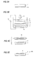
- Figs. 5A to 5D are views showing a manufacturing process for the speaker according to the first embodiment of the invention, in which Fig. 5A is a view showing a state where an ohmic electrode is formed, Fig. 5B is a view showing an anodization process, Fig. 5C is a view showing a quick thermal oxidation process, and Fig. 5D is a view showing a state where the exothermic electrode is formed.
- Fig. 6 is a view showing one example of exothermic electrode that is bent.
- Fig. 7 is a cross sectional view showing a speaker according to a second embodiment of the invention.
- Figs. 8A and 8B are views showing a speaker according to a third embodiment of the invention, in which Fig. 8A is a perspective view showing the speaker according to the third embodiment and Fig. 8B is a cross sectional view showing the speaker according to the third embodiment of the invention.
- Figs. 9A and 9B are views showing a speaker according to a fourth embodiment of the invention, in which Fig. 9A is a perspective view showing the speaker according to the fourth embodiment and Fig. 9B is a cross sectional view showing the speaker according to the fourth embodiment of the invention.
- Figs. 10A and 10B are views showing a speaker according to a fifth embodiment of the invention, in which Fig. 10A is a perspective view showing the speaker according to the fifth embodiment and Fig. 10B is a cross sectional view showing the speaker according to the fifth embodiment of the invention.
- Fig. 11 is a cross sectional view showing a speaker according to a sixth embodiment of the invention.
- Fig. 12 is a graph showing a frequency characteristic of the speaker according to the sixth embodiment of the invention.
- FIG. 1 is a cross-sectional view showing the speaker in the first embodiment
- Fig. 2 is a perspective view showing the speaker in the first embodiment.
- the speaker 100 comprises a silicone wafer 1 as a substrate, a thermal barrier layer 2 of an Si anodized film formed in rectangular shape by anodizing the silicone wafer 1, and an exothermic electrode 3 made of aluminum formed on the thermal barrier layer 2 in smaller rectangular shape than the thermal barrier layer 2.
- the shape of the silicone wafer 1 is rectangular, with a long side of 50mm, a short side of 20mm, and a thickness of 500 ⁇ m.
- the shape of the thermal barrier layer 2 is rectangular, with a long side of 45mm, a short side of 13mm, and a thickness of 20 ⁇ m.
- the shape of the exothermic electrode 3 is rectangular, with a long side of 40mm, a short side of 4mm, and a thickness of 330nm.
- an output terminal of an AC signal generator 21 is connected via a lead wire 3a to both ends of the exothermic electrode 3 (on the short side) . Then, if an AC electric field is applied, the temperature of the exothermic electrode 3 is varied like the alternating current due to the joule heating. At this time, a heat is hardly conducted to the thermal barrier layer 2 owing to a thermal barrier property of the thermal barrier layer 2, making the efficient heat exchange with the air in the vicinity of the surface of the exothermic electrode 3 to compress or expand the air, thereby producing an acoustic pressure . Aheat that can not be converted into acoustic pressure is radiated from the silicone wafer 1.
- Fig. 3 shows the relation of input or output of energy Q, surface temperature T and generated sound wave P, with respect to the temporal change of the alternating current I, when an AC electric field is applied to the exothermic electrode 3.
- the generated sound wave P has a double frequency of the applied AC frequency. It can be found that the phase of surface temperature T and generated sound wave P is delayed from the energy Q given to the exothermic electrode 3.
- a direct current with half or more the energy of the alternating current may be superposed on the alternating current.
- Fig. 4 shows a frequency characteristic of the speaker 100 that is measured by a microphone 22 placed at a position 1m away from the exothermic electrode 3, as shown in Figs. 1 and 2. As shown in Fig. 4, a sound pressure level of 90dB/W/m or greater is obtained in a frequency band of 10kHz or higher, and the sound pressure level drops with lower frequency.
- the rating of the AC signal generator 21 is from 0 to 100kHz, 30V, and 1A, no measurements are made in a higher frequency band, although the speaker 100 can produce a sound wave up to Giga-hertz band.
- Fig. 5A is a view showing a state where an ohmic electrode is formed
- Fig. 5B is a view showing a process of anodization
- Fig. 5C is a view showing a process of quick thermal oxidation
- Fig. 5D is a view showing a state where the exothermic electrode is formed.
- the thermal barrier layer 2 is formed by anodizing a part of the silicone wafer 1.
- Silicone of the silicone wafer 1 may be monocrystal, polycrystal, or amorphous, and take any crystal orientation. Also, it may be n-type doped, p-type doped, or non-doped.
- an ohmic electrode 6 is formed on one face of the silicone wafer 1 (i.e., a lower face in Fig. 5A) by vacuum deposition or sputtering, as shown in Fig. 5A. Also, an area except for an opening corresponding to a formation area of the thermal barrier layer 2 is masked with a masking material 7, as shown in Fig. 5B. Then, the substrate 1 is immersed in a mixture electrolyte solution 8 of fluoride and ethanol, and a platinum electrode 9 is arranged above the substrate 1 in Fig. 5B.
- a power source 10 is connected between the ohmic electrode 6 and the platinum electrode 9, and anodization is made at a low current (0.01 to 1A/cm 2 ), with the ohmic electrode 6 as anode and the platinum electrode 9 as cathode.
- anodization is performed by illuminating the substrate 1 with a lamp 11 to supply holes.
- the thermal barrier layer 2 formed by anodization becomes porous and is formed with micro pores having a diameter of about 2 to 100nm, when silicone of the silicone wafer 1 is n-type.
- the thermal barrier layer 2 has crystal lattice segmented and nanocrystalized, when silicone of the silicone wafer 1 is p-type. Further, holes that are carriers are consumed to make a depletion layer. In either case, the thermal barrier layer 2 can have a quite small thermal conductivity and a large electrical resistance. Then, the substrate 1 is taken out of the mixture electrolyte solution 8, and the masking material 7 and the ohmic electrode 6 are removed.
- the thermal barrier layer 2 may be heated by an infrared ray lamp 23 to make a quick thermal oxidation, as shown in Fig. 5C.
- the thermal barrier layer 2 that is an anodized layer has Si and SiOx mixed, but this ratio is adjusted through the quick thermal oxidation process, so that the optimal state can be obtained.
- the exothermic electrode 3 is formed by vacuum deposition or sputtering to fabricate the speaker 100, as shown in Fig. 5D.
- the silicone wafer is used, and anodized to form the thermal barrier layer, but instead of the silicone wafer, a substrate made of metal, alloy, or semiconductor that can be anodized may be employed.
- the thermal barrier layer may be formed by using the substrate made of metal, alloy or semiconductor, and laying down derivative, metal oxide, metal nitride, ceramic on the substrate by vacuum deposition, sputtering or CVD.
- the thermal barrier layer can be formed by coating a paste or suspension of derivative, metal oxide, metal nitride, or ceramics on the substrate by screen printing or spin coat, and then sintered.
- the substrate uses silicone as a material and the exothermic electrode uses aluminum as a material
- materials usable for the substrate or the exothermic electrode include simple substances of metal or its compound, such as Cu, Cr, Pt, Au, W, Ru, Ir, Al, Sc, Ti, V, Mn, Fe, Co, Ni, Zn, Ga, Y, Zr, Nb, Mo, Tc, Rh, Pd, Ag, Cd, Ln, Sn, Ta, Re, Os, Tl, Pb, La, Ce, Pr, Nd, Pm, Sm, Eu, Gd, Tb, Dy, Ho, Er, Tm, Yb, and Lu.
- the substrate or the exothermic electrode may be formed by laying down the metal or its compound as above cited.
- examples of usable material include metal oxides such as SiOx, LiOx, LiNx, NaOx, Kox, RbOx, CsOx, BeOx, MgOx, MgNx, CaOx, CaNx, SrOx, BaOx, ScOx, YOx, YNx, LaOx, LaNx, CeOx, PrOx, NdOx, SmOx, EuOx, GdOx, TbOx, DyOx, HoOx, ErOx, TmOx, YbOx, LuOx, TiOx, TiNx, ZrOx, ZrNx, HfOx, HfNx, ThOx, VOx, VNx, NbOx, TaOx, TaNx, CrOx, CrNx, MoOx, MoNx, WOx, WNx, MnOx, SiOx, LiOx, LiNx, NaOx, Kox, R
- the speaker 100 of this embodiment can be easily handled, because the exothermic electrode 3 is secured to the silicone wafer 1, and can produce a great volume of sound by inputting a large power into the exothermic electrode 3 because the heat not converted into sound wave is radiated via the silicone wafer 1. Also, owing to the use of the Joule heating, it is possible to obtain an essentially high acoustic conversion efficiency and a broad frequency band characteristic. Further, the speaker 1 is small and light, and of the thin type, whereby the entire apparatus can be reduced in size, weight and thickness as compared to the conventional speaker using a diaphragm.
- the exothermic electrode is formed in rectangular shape, but the exothermic electrode 31 may be formed in bent shape, as shown in Fig. 6.
- the impedance of the exothermic electrode can be controlled.
- a plurality of exothermic electrodes maybe provided, and driven in series or parallel.
- the shape of the substrate in the speaker of this invention is not limited.
- the substrate may take a shape like a primary curved surface, paraboloid, dome, sphere, or rugby ball.
- the shape of the exothermic electrode may be changed in accordance with the shape of the substrate to control the directivity of the generated sound wave.
- Fig. 7 is a cross-sectional view showing the speaker of the second embodiment.
- the thermal barrier layer 2 is formed by anodizing a part of the silicone wafer 1, a thermal barrier layer 2A of the speaker 200 in the second embodiment is formed on a substrate 1A, as shown in Fig. 6.
- the thermal barrier layer 2A can be formed by laying down derivative, metal oxide, metal nitride, or ceramics on the substrate 1A by sputtering or CVD.
- the thermal barrier layer 2A can be formed by coating a paste or suspension of derivative, metal oxide, metal nitride, or ceramics on the substrate 1A by screen printing or spin coat, and then sintered.
- an exothermic electrode 3A is formed on the thermal barrier layer 2A.
- the materials of the substrate 1A, the thermal barrier layer 2A and the exothermic electrode 3A may be those listed in the first embodiment.
- the shape of the exothermic electrode may be arbitrary. Also, a plurality of exothermic electrodes may be provided, and driven in series or parallel.
- Fig. 8A is a perspective view showing the speaker in the third embodiment
- Fig. 8B is a cross-sectional view showing the speaker of the third embodiment.
- the speaker 300 of this embodiment comprises a substrate 1B of curved shape, as shown in Fig. 8A and 8B.
- a thermal barrier layer 2B composed of an anodized film is formed on a part of the substrate 1B, and an exothermic electrode 3B is formed on the thermal barrier layer 2B.
- the thermal barrier layer 2B and the exothermic electrode 3B are curved according to a surface configuration of the substrate 1B constituting a primary curved face .
- the materials of the substrate 1B, the thermal barrier layer 2B and the exothermic electrode 3B may be those listed in the first embodiment.
- the thermal barrier layer may be formed on the substrate in the same manner as in the second embodiment.
- the shape of the exothermic electrode may be arbitrary. Also, a plurality of exothermic electrodes may be provided, and driven in series or parallel.
- Fig. 9A is a perspective view showing the speaker in the fourth embodiment
- Fig. 9B is a cross-sectional view showing the speaker of the fourth embodiment.
- the speaker 400 of this embodiment comprises a substrate 1C of hemispherical surface shape, as shown in Fig. 9A and 9B.
- a thermal barrier layer 2C is formed on the outer surface of the substrate 1C by anodizing the substrate 1C, and an exothermic electrode 3C is formed on the outer surface of the thermal barrier layer 2C.
- the thermal barrier layer 2C and the exothermic electrode 3C are curved according to a surface configuration of the substrate 1C constituting a part of sphere.
- the exothermic electrode 3C is formed in a shape constituting a part of sphere to widen the directivity of generated sound wave.
- the materials of the substrate 1C, the thermal barrier layer 2C and the exothermic electrode 3C may be those listed in the first embodiment.
- the thermal barrier layer may be formed on the substrate in the same manner as in the second embodiment.
- the shape of the exothermic electrode may be arbitrary. Also, a plurality of exothermic electrodes may be provided, and driven in series or parallel.
- Fig. 10A is a perspective view showing the speaker in the fifth embodiment
- Fig. 10B is a cross-sectional view showing the speaker of the fifth embodiment.
- the speaker 500 of this embodiment comprises a substrate 1D of spherical shape, as shown in Fig. 10A and 10B.
- a thermal barrier layer 2D is formed on the outer surface of abase substance 1D by anodizing a part of the base substance 1D, and an exothermic electrode 3D is formed on the outer surface of the thermal barrier layer 2D.
- the exothermic electrode 3D is formed according to a spherical shape, whereby the speaker has a non-directivity of radiating sound wave uniformly in substantially all directions.
- the thermal barrier layer may be formed on the substrate in the same manner as in the second embodiment.
- the materials of the base substance 1D, the thermal barrier layer 2D and the exothermic electrode 3D may be those listed in the first embodiment.
- the shape of the exothermic electrode may be arbitrary. Also, a plurality of exothermic electrodes may be provided, and driven in series or parallel.
- Fig. 11 is a cross-sectional view showing the speaker of the sixth embodiment
- Fig. 12 is a graph showing a frequency characteristic for the speaker of the sixth embodiment.
- the speaker 600 of the sixth embodiment has an acoustic horn 40 added to the speaker 100 of the first embodiment.
- the acoustic horn 40 presents a shape of sound path enlarging in section from a throat portion 40a positioned near the exothermic electrode 3 to an opening portion 40b.
- the speaker 600 of the sixth embodiment has a higher sound pressure level than the speaker 100 of the first embodiment.
- the speaker 600 that is more efficient particularly in a low frequency band approaches a flat frequency characteristic as a whole.
- the speaker 600 has a sound pressure level of 95dB/W/m or greater at 1kHz, 10kHz and 100kHz, 90dB/W/m or greater at 10Hz and 100Hz, and a characteristic of quite wide band, as shown in Fig. 12.
Abstract
Description
- The present invention relates to a speaker useful for the audio equipment, and more particularly to a speaker.
- An electro-acoustic transducer is well known in which an alternating current is introduced into a gold foil with only both ends fixed. If an alternating current is passed into the gold foil, the temperature of the gold foil changes, thereby causing a compression or expansion of the air nearby to produce an acoustic pressure.
- However, the gold foil for use is so thin as to fabricate and handle with difficulties, and is restricted in the input power, whereby a speaker is difficult to produce a sufficient sound volume.
- It is an object of this invention to provide a speaker that can be easily handled and can produce a sufficient sound volume.
- The present invention provides a speaker comprising a substrate, a thermal barrier layer formed on the substrate, and an exothermic electrode formed on the thermal barrier layer.
- This speaker can be easily handled because the exothermic electrode is fixed to the substrate, and can produce a large sound volume, because a heat not converted into the sound wave is radiated via the substrate and a large power can be input into the exothermic electrode. Owing to the use of the joule heating, the high acoustic efficiency can be attained, and the generated frequency band is broad. Further, the entire apparatus can be reduced in size, weight, and thickness. Further, the conformation of the exothermic electrode can be varied in arbitrary manner by changing the shape of the substrate, thereby controlling the directivity of generated sound wave at will.
- The thermal barrier layer may be formed by anodizing a part of the substrate. In this case, the normal semiconductor process may be utilized.
- The thermal barrier layer may be formed by supplying a material making up the thermal barrier layer on the substrate. In this case, the thermal barrier layer can be made of a material selected from a wide range of materials.
- The substrate may be made of silicone. In this case, the normal semiconductor process may be utilized
- The speaker may further comprise an acoustic horn for transmitting a sound wave arising in the vicinity of the exothermic electrode. In this case, because the acoustic horn can adjust the transmission characteristic, the speaker can achieve the desired characteristics by increasing the sound pressure level in a low frequency band, for example.
- The surface of the exothermic electrode may be formed in a planar shape. In this case, the speaker can be adjusted to have a narrower directivity.
- The surface of the exothermic electrode may be formed in a curved shape. In this case, the speaker can be afforded with a wider directivity than when the exothermic electrode is formed in planar shape.
- The surface of the exothermic electrode may be formed in a shape of constituting at least a part of sphere. In this case, the speaker can be afforded with a wider directivity than when the exothermic electrode is formed in planar shape. Also, the surface of the exothermic electrode is formed according to an almost spherical shape, whereby the speaker can have a non-directivity of radiating sound wave uniformly in substantially all directions.
- For an easy understanding of this invention, reference numerals employed in the accompanying drawings are written in parentheses, but this invention is not limited to the embodiments as shown in the drawings.
- Fig. 1 is a cross-sectional view showing a speaker according to a first embodiment of the present invention.
- Fig. 2 is a perspective view showing the speaker according to the first embodiment of the invention.
- Fig. 3 is a graph showing the relation of input and output of energy Q, surface temperature T and generated sound wave P with respect to the temporal change of the alternating current I, when an AC electric field is applied to an
exothermic electrode 3. - Fig. 4 is a graph showing a frequency characteristic of the speaker according to the first embodiment of the invention.
- Figs. 5A to 5D are views showing a manufacturing process for the speaker according to the first embodiment of the invention, in which Fig. 5A is a view showing a state where an ohmic electrode is formed, Fig. 5B is a view showing an anodization process, Fig. 5C is a view showing a quick thermal oxidation process, and Fig. 5D is a view showing a state where the exothermic electrode is formed.
- Fig. 6 is a view showing one example of exothermic electrode that is bent.
- Fig. 7 is a cross sectional view showing a speaker according to a second embodiment of the invention.
- Figs. 8A and 8B are views showing a speaker according to a third embodiment of the invention, in which Fig. 8A is a perspective view showing the speaker according to the third embodiment and Fig. 8B is a cross sectional view showing the speaker according to the third embodiment of the invention.
- Figs. 9A and 9B are views showing a speaker according to a fourth embodiment of the invention, in which Fig. 9A is a perspective view showing the speaker according to the fourth embodiment and Fig. 9B is a cross sectional view showing the speaker according to the fourth embodiment of the invention.
- Figs. 10A and 10B are views showing a speaker according to a fifth embodiment of the invention, in which Fig. 10A is a perspective view showing the speaker according to the fifth embodiment and Fig. 10B is a cross sectional view showing the speaker according to the fifth embodiment of the invention.
- Fig. 11 is a cross sectional view showing a speaker according to a sixth embodiment of the invention.
- Fig. 12 is a graph showing a frequency characteristic of the speaker according to the sixth embodiment of the invention.
- Now, a description will be given in more detail of preferred embodiments of the invention with reference to the accompanying drawings.
- A speaker according to one embodiment of the present invention will be described below with reference to Figs. 1 to 6. Fig. 1 is a cross-sectional view showing the speaker in the first embodiment, and Fig. 2 is a perspective view showing the speaker in the first embodiment.
- As shown in Figs. 1 and 2, the
speaker 100 comprises asilicone wafer 1 as a substrate, athermal barrier layer 2 of an Si anodized film formed in rectangular shape by anodizing thesilicone wafer 1, and anexothermic electrode 3 made of aluminum formed on thethermal barrier layer 2 in smaller rectangular shape than thethermal barrier layer 2. - The shape of the
silicone wafer 1 is rectangular, with a long side of 50mm, a short side of 20mm, and a thickness of 500µm. The shape of thethermal barrier layer 2 is rectangular, with a long side of 45mm, a short side of 13mm, and a thickness of 20µm. The shape of theexothermic electrode 3 is rectangular, with a long side of 40mm, a short side of 4mm, and a thickness of 330nm. - The operation of the
speaker 100 will be described below. As shown in Fig. 2, an output terminal of anAC signal generator 21 is connected via alead wire 3a to both ends of the exothermic electrode 3 (on the short side) . Then, if an AC electric field is applied, the temperature of theexothermic electrode 3 is varied like the alternating current due to the joule heating. At this time, a heat is hardly conducted to thethermal barrier layer 2 owing to a thermal barrier property of thethermal barrier layer 2, making the efficient heat exchange with the air in the vicinity of the surface of theexothermic electrode 3 to compress or expand the air, thereby producing an acoustic pressure . Aheat that can not be converted into acoustic pressure is radiated from thesilicone wafer 1. - Fig. 3 shows the relation of input or output of energy Q, surface temperature T and generated sound wave P, with respect to the temporal change of the alternating current I, when an AC electric field is applied to the
exothermic electrode 3. As shown in Fig. 3, the generated sound wave P has a double frequency of the applied AC frequency. It can be found that the phase of surface temperature T and generated sound wave P is delayed from the energy Q given to theexothermic electrode 3. In the case where the generated sound wave P having the same frequency as the applied AC frequency is desired to obtain, a direct current with half or more the energy of the alternating current may be superposed on the alternating current. - Fig. 4 shows a frequency characteristic of the
speaker 100 that is measured by amicrophone 22 placed at aposition 1m away from theexothermic electrode 3, as shown in Figs. 1 and 2. As shown in Fig. 4, a sound pressure level of 90dB/W/m or greater is obtained in a frequency band of 10kHz or higher, and the sound pressure level drops with lower frequency. - Since the rating of the
AC signal generator 21 is from 0 to 100kHz, 30V, and 1A, no measurements are made in a higher frequency band, although thespeaker 100 can produce a sound wave up to Giga-hertz band. - Referring now to Figs. 5A to 5D, a manufacturing method for the
speaker 100 will be described below. Fig. 5A is a view showing a state where an ohmic electrode is formed, Fig. 5B is a view showing a process of anodization, Fig. 5C is a view showing a process of quick thermal oxidation, and Fig. 5D is a view showing a state where the exothermic electrode is formed. - The
thermal barrier layer 2 is formed by anodizing a part of thesilicone wafer 1. Silicone of thesilicone wafer 1 may be monocrystal, polycrystal, or amorphous, and take any crystal orientation. Also, it may be n-type doped, p-type doped, or non-doped. - First of all, an
ohmic electrode 6 is formed on one face of the silicone wafer 1 (i.e., a lower face in Fig. 5A) by vacuum deposition or sputtering, as shown in Fig. 5A. Also, an area except for an opening corresponding to a formation area of thethermal barrier layer 2 is masked with a maskingmaterial 7, as shown in Fig. 5B. Then, thesubstrate 1 is immersed in a mixture electrolyte solution 8 of fluoride and ethanol, and aplatinum electrode 9 is arranged above thesubstrate 1 in Fig. 5B. Apower source 10 is connected between theohmic electrode 6 and theplatinum electrode 9, and anodization is made at a low current (0.01 to 1A/cm2), with theohmic electrode 6 as anode and theplatinum electrode 9 as cathode. When thesilicone wafer 1 is n-type, anodization is performed by illuminating thesubstrate 1 with alamp 11 to supply holes. - The
thermal barrier layer 2 formed by anodization becomes porous and is formed with micro pores having a diameter of about 2 to 100nm, when silicone of thesilicone wafer 1 is n-type. Thethermal barrier layer 2 has crystal lattice segmented and nanocrystalized, when silicone of thesilicone wafer 1 is p-type. Further, holes that are carriers are consumed to make a depletion layer. In either case, thethermal barrier layer 2 can have a quite small thermal conductivity and a large electrical resistance. Then, thesubstrate 1 is taken out of the mixture electrolyte solution 8, and the maskingmaterial 7 and theohmic electrode 6 are removed. - In order to further enhance the characteristic of the
thermal barrier layer 2, thethermal barrier layer 2 may be heated by aninfrared ray lamp 23 to make a quick thermal oxidation, as shown in Fig. 5C. In either case where silicone is n-type or p-type, thethermal barrier layer 2 that is an anodized layer has Si and SiOx mixed, but this ratio is adjusted through the quick thermal oxidation process, so that the optimal state can be obtained. - Lastly, the
exothermic electrode 3 is formed by vacuum deposition or sputtering to fabricate thespeaker 100, as shown in Fig. 5D. - In the above embodiment, the silicone wafer is used, and anodized to form the thermal barrier layer, but instead of the silicone wafer, a substrate made of metal, alloy, or semiconductor that can be anodized may be employed.
- Also, instead of forming the thermal barrier layer by anodizing the substrate, the thermal barrier layer may be formed by using the substrate made of metal, alloy or semiconductor, and laying down derivative, metal oxide, metal nitride, ceramic on the substrate by vacuum deposition, sputtering or CVD. The thermal barrier layer can be formed by coating a paste or suspension of derivative, metal oxide, metal nitride, or ceramics on the substrate by screen printing or spin coat, and then sintered.
- In the above embodiment, the substrate uses silicone as a material and the exothermic electrode uses aluminum as a material, but materials usable for the substrate or the exothermic electrode include simple substances of metal or its compound, such as Cu, Cr, Pt, Au, W, Ru, Ir, Al, Sc, Ti, V, Mn, Fe, Co, Ni, Zn, Ga, Y, Zr, Nb, Mo, Tc, Rh, Pd, Ag, Cd, Ln, Sn, Ta, Re, Os, Tl, Pb, La, Ce, Pr, Nd, Pm, Sm, Eu, Gd, Tb, Dy, Ho, Er, Tm, Yb, and Lu. Also, the substrate or the exothermic electrode may be formed by laying down the metal or its compound as above cited.
- Also, in the case where the thermal barrier material is formed by sputtering or CVD, examples of usable material include metal oxides such as SiOx, LiOx, LiNx, NaOx, Kox, RbOx, CsOx, BeOx, MgOx, MgNx, CaOx, CaNx, SrOx, BaOx, ScOx, YOx, YNx, LaOx, LaNx, CeOx, PrOx, NdOx, SmOx, EuOx, GdOx, TbOx, DyOx, HoOx, ErOx, TmOx, YbOx, LuOx, TiOx, TiNx, ZrOx, ZrNx, HfOx, HfNx, ThOx, VOx, VNx, NbOx, TaOx, TaNx, CrOx, CrNx, MoOx, MoNx, WOx, WNx, MnOx, ReOx, FeOx, FeNx, RuOx, OsOx, CoOx, RhOx, IrOx, NiOx, PbOx, PtOx, CuOx, CuNx, AgOx, AuOx, ZnOx, CdOx, HgOx, BOx, BNx, AlOx, AlNx, GaOx, GaNx, InOx, TiOx, TiNx, SiNx, GeOx, SnOx, PbOx, POx, PNx, AsOx, SbOx, SeOx, and TeOx, metal double oxides such as LiAlO2, Li2SiO3, Li2TiO3, Na2Al22O34, NaFeO2, Na4SiO4, K2SiO3, K2TiO3, K2WO4, Rb2CrO4, Cs2CrO4, MgAl2O4, MgFe2O4, MgTiO3, CaTiO3, CaWO4, CaZrO3, SrFe12O19, SrTiO3, SrZrO3, BaAl2O4, BaFe12O19, BaTiO3, Y3A15O12, Y3Fe5O12, LaFeO3, La3Fe5O12, La2Ti2O7, CeSnO4, CeTiO4, Sm3Fe5O12, EuFeO3, Eu3Fe5O12, GdFeO3, Gd3Fe5O12, DyFeO3, Dy3Fe5O12, HoFeO3, Ho3Fe5O12, ErFeO3, Er3Fe5O12, Tm3Fe5O12, LuFeO3, Lu3Fe5O12, NiTiO3, Al2TiO3, FeTiO3, BaZrO3, LiZrO3, MgZrO3, HfTiO4, NH4VO3, AgVO3, LiVO3, BaNb2O6, NaNbO3, SrNb2O6, KTaO3, NaTaO3, SrTa2O6, CuCr2O4, Ag2CrO4, BaCrO4, K2MoO4, Na2MoO4, NiMoO4, BaWO4, Na2WO4, SrWO4, MnCr2O4, MnFe2O4, MnTiO3, MnWO4, CoFe2O4, ZnFe2O4, FeWO4, CoMoO4, CuTiO3, CuWO4, Ag2MoO4, Ag2WO4, ZnAl2O4, ZnMoO4, ZnWO4, CdSnO3, CdTiO3, CdMoO4, CdWO4, NaAlO2, MgAl2O4, SrAl2O4, Gd3Ga5O12, InFeO3, MgIn2O4, Al2TiO4, FeTiO3, MgTiO3, NaSiO3, CaSiO3, ZrSiO4, K2GeO3, Li2GeO3, Na2GeO3, Bi2Sn3O9, MgSnO3, SrSnO3, PbSiO3, PbMoO4, PbTiO3, SnO2·Sb2O3, CuSeO4, Na2SeO3, ZnSeO3, K2TeO3, K2TeO4, Na2TeO3, and Na2TeO4, sulfides such as FeS, Al2S3, MgS, and ZnS, and fluorides such as LiF, MgF2, and SmF3, chlorides such as HgCl, FeCl2, and CrCl3, bromides such as AgBr, CuBr, and MnBr2, iodides such as PbI2, CuI and FeI2, and metal oxide nitrides such as SiAlON.
- The
speaker 100 of this embodiment can be easily handled, because theexothermic electrode 3 is secured to thesilicone wafer 1, and can produce a great volume of sound by inputting a large power into theexothermic electrode 3 because the heat not converted into sound wave is radiated via thesilicone wafer 1. Also, owing to the use of the Joule heating, it is possible to obtain an essentially high acoustic conversion efficiency and a broad frequency band characteristic. Further, thespeaker 1 is small and light, and of the thin type, whereby the entire apparatus can be reduced in size, weight and thickness as compared to the conventional speaker using a diaphragm. - In the above embodiment, the exothermic electrode is formed in rectangular shape, but the
exothermic electrode 31 may be formed in bent shape, as shown in Fig. 6. By changing the shape of the exothermic electrode in this manner, the impedance of the exothermic electrode can be controlled. Also, a plurality of exothermic electrodes maybe provided, and driven in series or parallel. - The shape of the substrate in the speaker of this invention is not limited. For example, the substrate may take a shape like a primary curved surface, paraboloid, dome, sphere, or Rugby ball. The shape of the exothermic electrode may be changed in accordance with the shape of the substrate to control the directivity of the generated sound wave.
- Referring to Fig. 7, a speaker according to a second embodiment of the invention will be described below. Fig. 7 is a cross-sectional view showing the speaker of the second embodiment.
- Though in the first embodiment, the
thermal barrier layer 2 is formed by anodizing a part of thesilicone wafer 1, athermal barrier layer 2A of thespeaker 200 in the second embodiment is formed on asubstrate 1A, as shown in Fig. 6. Thethermal barrier layer 2A can be formed by laying down derivative, metal oxide, metal nitride, or ceramics on thesubstrate 1A by sputtering or CVD. For example, thethermal barrier layer 2A can be formed by coating a paste or suspension of derivative, metal oxide, metal nitride, or ceramics on thesubstrate 1A by screen printing or spin coat, and then sintered. Further, anexothermic electrode 3A is formed on thethermal barrier layer 2A. - Note that the materials of the
substrate 1A, thethermal barrier layer 2A and theexothermic electrode 3A may be those listed in the first embodiment. - The shape of the exothermic electrode may be arbitrary. Also, a plurality of exothermic electrodes may be provided, and driven in series or parallel.
- Referring to Figs. 8A and 8B, a speaker according to a third embodiment of the invention will be described below. Fig. 8A is a perspective view showing the speaker in the third embodiment, and Fig. 8B is a cross-sectional view showing the speaker of the third embodiment.
- The
speaker 300 of this embodiment comprises asubstrate 1B of curved shape, as shown in Fig. 8A and 8B. Athermal barrier layer 2B composed of an anodized film is formed on a part of thesubstrate 1B, and anexothermic electrode 3B is formed on thethermal barrier layer 2B. Thethermal barrier layer 2B and theexothermic electrode 3B are curved according to a surface configuration of thesubstrate 1B constituting a primary curved face . By changing the shape of the exothermic electrode according to the shape of thesubstrate 1B in this way, the directivity of the generated sound wave that is different from the exothermic electrode formed in planar shape can be obtained. - Note that the materials of the
substrate 1B, thethermal barrier layer 2B and theexothermic electrode 3B may be those listed in the first embodiment. - The thermal barrier layer may be formed on the substrate in the same manner as in the second embodiment.
- The shape of the exothermic electrode may be arbitrary. Also, a plurality of exothermic electrodes may be provided, and driven in series or parallel.
- Referring to Figs. 9A and 9B, a speaker according to a fourth embodiment of the invention will be described below. Fig. 9A is a perspective view showing the speaker in the fourth embodiment, and Fig. 9B is a cross-sectional view showing the speaker of the fourth embodiment.
- The
speaker 400 of this embodiment comprises asubstrate 1C of hemispherical surface shape, as shown in Fig. 9A and 9B. Athermal barrier layer 2C is formed on the outer surface of thesubstrate 1C by anodizing thesubstrate 1C, and anexothermic electrode 3C is formed on the outer surface of thethermal barrier layer 2C. Thethermal barrier layer 2C and theexothermic electrode 3C are curved according to a surface configuration of thesubstrate 1C constituting a part of sphere. In this embodiment, theexothermic electrode 3C is formed in a shape constituting a part of sphere to widen the directivity of generated sound wave. - Note that the materials of the
substrate 1C, thethermal barrier layer 2C and theexothermic electrode 3C may be those listed in the first embodiment. - The thermal barrier layer may be formed on the substrate in the same manner as in the second embodiment.
- The shape of the exothermic electrode may be arbitrary. Also, a plurality of exothermic electrodes may be provided, and driven in series or parallel.
- Referring to Figs. 10A and 10B, a speaker according to a fifth embodiment of the invention will be described below. Fig. 10A is a perspective view showing the speaker in the fifth embodiment, and Fig. 10B is a cross-sectional view showing the speaker of the fifth embodiment.
- The
speaker 500 of this embodiment comprises asubstrate 1D of spherical shape, as shown in Fig. 10A and 10B. Athermal barrier layer 2D is formed on the outer surface ofabase substance 1D by anodizing a part of thebase substance 1D, and anexothermic electrode 3D is formed on the outer surface of thethermal barrier layer 2D. In this embodiment, theexothermic electrode 3D is formed according to a spherical shape, whereby the speaker has a non-directivity of radiating sound wave uniformly in substantially all directions. - The thermal barrier layer may be formed on the substrate in the same manner as in the second embodiment.
- Note that the materials of the
base substance 1D, thethermal barrier layer 2D and theexothermic electrode 3D may be those listed in the first embodiment. - The shape of the exothermic electrode may be arbitrary. Also, a plurality of exothermic electrodes may be provided, and driven in series or parallel.
- Referring to Figs. 11 and 12, a speaker according to a sixth embodiment of the invention will be described below. Fig. 11 is a cross-sectional view showing the speaker of the sixth embodiment, and Fig. 12 is a graph showing a frequency characteristic for the speaker of the sixth embodiment.
- As shown in Fig. 11, the
speaker 600 of the sixth embodiment has anacoustic horn 40 added to thespeaker 100 of the first embodiment. Theacoustic horn 40 presents a shape of sound path enlarging in section from athroat portion 40a positioned near theexothermic electrode 3 to anopening portion 40b. - As shown in Fig. 12, the
speaker 600 of the sixth embodiment has a higher sound pressure level than thespeaker 100 of the first embodiment. Thespeaker 600 that is more efficient particularly in a low frequency band approaches a flat frequency characteristic as a whole. Thespeaker 600 has a sound pressure level of 95dB/W/m or greater at 1kHz, 10kHz and 100kHz, 90dB/W/m or greater at 10Hz and 100Hz, and a characteristic of quite wide band, as shown in Fig. 12. - Note that the speaker can be modified in various ways as described in the first embodiment.
Claims (8)
- A speaker with the joule heating, comprising:a substrate;a thermal barrier layer formed on said substrate; andan exothermic electrode formed on said thermal barrier layer.
- The speaker according to claim 1, wherein said thermal barrier layer is formed by anodizing a part of said substrate.
- The speaker according to claim 1, wherein said thermal barrier layer is formed by supplying a material making up said thermal barrier layer on said substrate.
- The speaker according to claim 1, wherein said substrate is made of silicone.
- The speaker according to claim 1, further comprising an acoustic horn for transmitting a sound wave arising in the vicinity of said exothermic electrode.
- The speaker according to claim 1, wherein the surface of said exothermic electrode is formed in a planar shape.
- The speaker according to claim 1, wherein the surface of said exothermic electrode is formed in a curved shape.
- The speaker according to claim 1, wherein the surface of said exothermic electrode is formed in a shape of constituting at least a part of sphere.
Applications Claiming Priority (2)
| Application Number | Priority Date | Filing Date | Title |
|---|---|---|---|
| JP2000381409 | 2000-12-15 | ||
| JP2000381409A JP2002186097A (en) | 2000-12-15 | 2000-12-15 | Speaker |
Publications (2)
| Publication Number | Publication Date |
|---|---|
| EP1215936A2 true EP1215936A2 (en) | 2002-06-19 |
| EP1215936A3 EP1215936A3 (en) | 2003-07-02 |
Family
ID=18849410
Family Applications (1)
| Application Number | Title | Priority Date | Filing Date |
|---|---|---|---|
| EP01310349A Withdrawn EP1215936A3 (en) | 2000-12-15 | 2001-12-11 | Speaker |
Country Status (3)
| Country | Link |
|---|---|
| US (1) | US20020076070A1 (en) |
| EP (1) | EP1215936A3 (en) |
| JP (1) | JP2002186097A (en) |
Cited By (6)
| Publication number | Priority date | Publication date | Assignee | Title |
|---|---|---|---|---|
| EP1599068A1 (en) * | 2003-02-28 | 2005-11-23 | Tokyo University of Agriculture and Technology Tlo Co., Ltd. | Thermally excited sound wave generating device |
| WO2006011650A2 (en) * | 2004-07-27 | 2006-02-02 | Matsushita Electric Works, Ltd. | Acoustic wave sensor |
| EP1916870A1 (en) * | 2005-10-26 | 2008-04-30 | Matsushita Electric Works, Ltd. | Pressure wave generator and production method therefor |
| EP2217006A1 (en) * | 2009-02-04 | 2010-08-11 | Oticon A/S | A hearing device |
| CN1954640B (en) * | 2004-04-28 | 2011-07-27 | 松下电工株式会社 | Pressure wave generator and method for fabricating the same |
| GB2601835A (en) * | 2020-12-14 | 2022-06-15 | Soliton Holdings Corp | Apparatuses based on jet-effect and thermo-electric effect |
Families Citing this family (40)
| Publication number | Priority date | Publication date | Assignee | Title |
|---|---|---|---|---|
| US7160577B2 (en) | 2002-05-02 | 2007-01-09 | Micron Technology, Inc. | Methods for atomic-layer deposition of aluminum oxides in integrated circuits |
| JP2005291941A (en) * | 2004-03-31 | 2005-10-20 | Matsushita Electric Works Ltd | Ultrasonic sensor and wave transmitting element for the same |
| JP4617710B2 (en) * | 2004-04-28 | 2011-01-26 | パナソニック電工株式会社 | Pressure wave generator |
| JP4649929B2 (en) * | 2004-09-27 | 2011-03-16 | パナソニック電工株式会社 | Pressure wave generator |
| JP4505672B2 (en) * | 2004-04-28 | 2010-07-21 | パナソニック電工株式会社 | Pressure wave generator and manufacturing method thereof |
| JP4617803B2 (en) * | 2004-09-27 | 2011-01-26 | パナソニック電工株式会社 | Pressure wave generator |
| JP4682573B2 (en) * | 2004-09-27 | 2011-05-11 | パナソニック電工株式会社 | Pressure wave generator |
| US7662729B2 (en) | 2005-04-28 | 2010-02-16 | Micron Technology, Inc. | Atomic layer deposition of a ruthenium layer to a lanthanide oxide dielectric layer |
| US7572695B2 (en) | 2005-05-27 | 2009-08-11 | Micron Technology, Inc. | Hafnium titanium oxide films |
| US7927948B2 (en) | 2005-07-20 | 2011-04-19 | Micron Technology, Inc. | Devices with nanocrystals and methods of formation |
| JP4742907B2 (en) * | 2006-02-23 | 2011-08-10 | パナソニック電工株式会社 | Pressure wave generating element and manufacturing method thereof |
| JP5116269B2 (en) * | 2006-08-25 | 2013-01-09 | 株式会社ジャパンディスプレイイースト | Image display device |
| EP2061098A4 (en) * | 2006-09-05 | 2011-06-01 | Pioneer Corp | Thermal sound generating device |
| US8270639B2 (en) | 2008-04-28 | 2012-09-18 | Tsinghua University | Thermoacoustic device |
| US8259968B2 (en) | 2008-04-28 | 2012-09-04 | Tsinghua University | Thermoacoustic device |
| US8259967B2 (en) | 2008-04-28 | 2012-09-04 | Tsinghua University | Thermoacoustic device |
| US8249279B2 (en) | 2008-04-28 | 2012-08-21 | Beijing Funate Innovation Technology Co., Ltd. | Thermoacoustic device |
| US8452031B2 (en) | 2008-04-28 | 2013-05-28 | Tsinghua University | Ultrasonic thermoacoustic device |
| CN101820571B (en) * | 2009-02-27 | 2013-12-11 | 清华大学 | Speaker system |
| CN101656907B (en) | 2008-08-22 | 2013-03-20 | 清华大学 | Sound box |
| CN101713531B (en) | 2008-10-08 | 2013-08-28 | 清华大学 | Sounding type lighting device |
| CN101715155B (en) | 2008-10-08 | 2013-07-03 | 清华大学 | Earphone |
| CN101715160B (en) | 2008-10-08 | 2013-02-13 | 清华大学 | Flexible sound producing device and sound producing flag |
| CN101771922B (en) | 2008-12-30 | 2013-04-24 | 清华大学 | Sounding device |
| US8300855B2 (en) | 2008-12-30 | 2012-10-30 | Beijing Funate Innovation Technology Co., Ltd. | Thermoacoustic module, thermoacoustic device, and method for making the same |
| US8325947B2 (en) * | 2008-12-30 | 2012-12-04 | Bejing FUNATE Innovation Technology Co., Ltd. | Thermoacoustic device |
| TWI411314B (en) * | 2009-01-16 | 2013-10-01 | Beijing Funate Innovation Tech | Thermal acoustic device |
| TWI382772B (en) * | 2009-01-16 | 2013-01-11 | Beijing Funate Innovation Tech | Thermoacoustic device |
| US8231795B2 (en) * | 2009-05-01 | 2012-07-31 | Avago Technologies Wireless Ip (Singapore) Pte. Ltd. | Micromachined horn |
| CN101922755A (en) | 2009-06-09 | 2010-12-22 | 清华大学 | Heating wall |
| CN101943850B (en) * | 2009-07-03 | 2013-04-24 | 清华大学 | Sound-producing screen and projection system using same |
| CN101990152B (en) | 2009-08-07 | 2013-08-28 | 清华大学 | Thermal sounding device and manufacturing method thereof |
| CN102006542B (en) | 2009-08-28 | 2014-03-26 | 清华大学 | Sound generating device |
| CN102023297B (en) | 2009-09-11 | 2015-01-21 | 清华大学 | Sonar system |
| CN102034467B (en) | 2009-09-25 | 2013-01-30 | 北京富纳特创新科技有限公司 | Sound production device |
| CN102056064B (en) | 2009-11-06 | 2013-11-06 | 清华大学 | Loudspeaker |
| CN102056065B (en) | 2009-11-10 | 2014-11-12 | 北京富纳特创新科技有限公司 | Sound production device |
| CN102065363B (en) * | 2009-11-16 | 2013-11-13 | 北京富纳特创新科技有限公司 | Sound production device |
| JP2012054762A (en) * | 2010-09-01 | 2012-03-15 | Nippon Hoso Kyokai <Nhk> | Thin film sound wave outlet device |
| JP2013187845A (en) * | 2012-03-09 | 2013-09-19 | Nippon Hoso Kyokai <Nhk> | Speaker element |
Citations (5)
| Publication number | Priority date | Publication date | Assignee | Title |
|---|---|---|---|---|
| US3407273A (en) * | 1965-01-08 | 1968-10-22 | Stanford Research Inst | Thermoacoustic loudspeaker |
| US3460005A (en) * | 1964-09-30 | 1969-08-05 | Hitachi Ltd | Insulated gate field effect transistors with piezoelectric substrates |
| DE2417962A1 (en) * | 1974-04-11 | 1975-10-23 | Max Planck Gesellschaft | Piezoelectric mechanical oscillations to voltage transducer - uses bent piezoelectric foil connected to device generating electric field |
| US4638207A (en) * | 1986-03-19 | 1987-01-20 | Pennwalt Corporation | Piezoelectric polymeric film balloon speaker |
| JPH03140100A (en) * | 1989-10-26 | 1991-06-14 | Fuji Xerox Co Ltd | Electroacoustic transducing method and apparatus therefor |
-
2000
- 2000-12-15 JP JP2000381409A patent/JP2002186097A/en active Pending
-
2001
- 2001-12-11 US US10/011,770 patent/US20020076070A1/en not_active Abandoned
- 2001-12-11 EP EP01310349A patent/EP1215936A3/en not_active Withdrawn
Patent Citations (5)
| Publication number | Priority date | Publication date | Assignee | Title |
|---|---|---|---|---|
| US3460005A (en) * | 1964-09-30 | 1969-08-05 | Hitachi Ltd | Insulated gate field effect transistors with piezoelectric substrates |
| US3407273A (en) * | 1965-01-08 | 1968-10-22 | Stanford Research Inst | Thermoacoustic loudspeaker |
| DE2417962A1 (en) * | 1974-04-11 | 1975-10-23 | Max Planck Gesellschaft | Piezoelectric mechanical oscillations to voltage transducer - uses bent piezoelectric foil connected to device generating electric field |
| US4638207A (en) * | 1986-03-19 | 1987-01-20 | Pennwalt Corporation | Piezoelectric polymeric film balloon speaker |
| JPH03140100A (en) * | 1989-10-26 | 1991-06-14 | Fuji Xerox Co Ltd | Electroacoustic transducing method and apparatus therefor |
Non-Patent Citations (1)
| Title |
|---|
| PATENT ABSTRACTS OF JAPAN vol. 015, no. 359 (E-1110), 11 September 1991 (1991-09-11) & JP 03 140100 A (FUJI XEROX CO LTD), 14 June 1991 (1991-06-14) * |
Cited By (15)
| Publication number | Priority date | Publication date | Assignee | Title |
|---|---|---|---|---|
| EP1599068A1 (en) * | 2003-02-28 | 2005-11-23 | Tokyo University of Agriculture and Technology Tlo Co., Ltd. | Thermally excited sound wave generating device |
| EP1599068A4 (en) * | 2003-02-28 | 2009-04-22 | Univ Tokyo Agriculture & Technology Tlo Co Ltd | Thermally excited sound wave generating device |
| CN1954640B (en) * | 2004-04-28 | 2011-07-27 | 松下电工株式会社 | Pressure wave generator and method for fabricating the same |
| WO2006011650A2 (en) * | 2004-07-27 | 2006-02-02 | Matsushita Electric Works, Ltd. | Acoustic wave sensor |
| WO2006011650A3 (en) * | 2004-07-27 | 2006-03-23 | Matsushita Electric Works Ltd | Acoustic wave sensor |
| US8254209B2 (en) | 2004-07-27 | 2012-08-28 | Panasonic Corporation | Acoustic wave sensor |
| KR100915486B1 (en) * | 2004-07-27 | 2009-09-03 | 파나소닉 전공 주식회사 | Acoustic wave sensor |
| CN1989418B (en) * | 2004-07-27 | 2010-05-05 | 松下电工株式会社 | Acoustic wave sensor |
| EP1916870A1 (en) * | 2005-10-26 | 2008-04-30 | Matsushita Electric Works, Ltd. | Pressure wave generator and production method therefor |
| US7881157B2 (en) | 2005-10-26 | 2011-02-01 | Panasonic Electric Works Co., Ltd, | Pressure wave generator and production method therefor |
| EP1916870A4 (en) * | 2005-10-26 | 2009-07-29 | Panasonic Elec Works Co Ltd | Pressure wave generator and production method therefor |
| EP2217006A1 (en) * | 2009-02-04 | 2010-08-11 | Oticon A/S | A hearing device |
| US8644540B2 (en) | 2009-02-04 | 2014-02-04 | Oticon A/S | Hearing device |
| GB2601835A (en) * | 2020-12-14 | 2022-06-15 | Soliton Holdings Corp | Apparatuses based on jet-effect and thermo-electric effect |
| GB2601835B (en) * | 2020-12-14 | 2023-01-25 | Soliton Holdings Corp | Apparatuses based on jet-effect and thermoelectric effect |
Also Published As
| Publication number | Publication date |
|---|---|
| US20020076070A1 (en) | 2002-06-20 |
| JP2002186097A (en) | 2002-06-28 |
| EP1215936A3 (en) | 2003-07-02 |
Similar Documents
| Publication | Publication Date | Title |
|---|---|---|
| EP1215936A2 (en) | Speaker | |
| Li et al. | Preparation of sandwich-like NiCo 2 O 4/rGO/NiO heterostructure on nickel foam for high-performance supercapacitor electrodes | |
| KR101454686B1 (en) | Apparatus and method for converting energy | |
| Ma et al. | Self-supported formation of hierarchical NiCo 2 O 4 tetragonal microtubes with enhanced electrochemical properties | |
| US6023124A (en) | Electron emission device and display device using the same | |
| TWI645333B (en) | Sound output apparatus | |
| Liu et al. | Self-assembled hierarchical yolk–shell structured NiO@ C from metal–organic frameworks with outstanding performance for lithium storage | |
| JP2010093804A (en) | Earphone | |
| US6400070B1 (en) | Electron emission device and display device using the same | |
| JPH0365070A (en) | Piezoelectricity/bending converter | |
| JPH11300274A (en) | Pressure wave generation device | |
| JP2008113280A (en) | Microphone | |
| EP0896355B1 (en) | Electron emission device and display device using the same | |
| TWI342635B (en) | Fuel cell and passive support | |
| JP5171988B2 (en) | Electron-emitting device, display device using electron-emitting device, and method for manufacturing electron-emitting device | |
| JP2005512280A (en) | ELECTRON EMITTING ELEMENT, MANUFACTURING METHOD THEREOF, AND DISPLAY DEVICE USING ELECTRON EMITTING ELEMENT | |
| Nayak et al. | Urchin-like NiCo2O4 microsphere by hydrothermal route: structural, electrochemical, optical and magnetic properties | |
| JP7025644B2 (en) | Metal-air battery and air electrode manufacturing method | |
| CN101820572A (en) | Thermoacoustic device | |
| CN101971285B (en) | High frequency triode-type field emission device and process for manufacturing same | |
| US20140041210A1 (en) | Methods for fabricating lithium battery anodes | |
| Fletcher et al. | Field emission from nanometer-scale tips of crystalline PbZrxTi1− xO3 | |
| US20140140544A1 (en) | Earphone | |
| US20140140550A1 (en) | Thermoacoustic device array | |
| JP2006111503A (en) | Composite material containing dispersed ultrafine metal particles and manufacturing method thereof |
Legal Events
| Date | Code | Title | Description |
|---|---|---|---|
| PUAI | Public reference made under article 153(3) epc to a published international application that has entered the european phase |
Free format text: ORIGINAL CODE: 0009012 |
|
| AK | Designated contracting states |
Kind code of ref document: A2 Designated state(s): AT BE CH CY DE DK ES FI FR GB GR IE IT LI LU MC NL PT SE TR |
|
| AX | Request for extension of the european patent |
Free format text: AL;LT;LV;MK;RO;SI |
|
| PUAL | Search report despatched |
Free format text: ORIGINAL CODE: 0009013 |
|
| AK | Designated contracting states |
Designated state(s): AT BE CH CY DE DK ES FI FR GB GR IE IT LI LU MC NL PT SE TR |
|
| AX | Request for extension of the european patent |
Extension state: AL LT LV MK RO SI |
|
| 17P | Request for examination filed |
Effective date: 20031230 |
|
| AKX | Designation fees paid |
Designated state(s): DE FR GB |
|
| STAA | Information on the status of an ep patent application or granted ep patent |
Free format text: STATUS: THE APPLICATION IS DEEMED TO BE WITHDRAWN |
|
| 18D | Application deemed to be withdrawn |
Effective date: 20070703 |