EP1207396A1 - Fluid dispenser - Google Patents
Fluid dispenser Download PDFInfo
- Publication number
- EP1207396A1 EP1207396A1 EP00810970A EP00810970A EP1207396A1 EP 1207396 A1 EP1207396 A1 EP 1207396A1 EP 00810970 A EP00810970 A EP 00810970A EP 00810970 A EP00810970 A EP 00810970A EP 1207396 A1 EP1207396 A1 EP 1207396A1
- Authority
- EP
- European Patent Office
- Prior art keywords
- fluid
- needle
- valve
- conduit
- liquid
- Prior art date
- Legal status (The legal status is an assumption and is not a legal conclusion. Google has not performed a legal analysis and makes no representation as to the accuracy of the status listed.)
- Withdrawn
Links
Images

Classifications
-
- G—PHYSICS
- G01—MEASURING; TESTING
- G01N—INVESTIGATING OR ANALYSING MATERIALS BY DETERMINING THEIR CHEMICAL OR PHYSICAL PROPERTIES
- G01N35/00—Automatic analysis not limited to methods or materials provided for in any single one of groups G01N1/00 - G01N33/00; Handling materials therefor
- G01N35/10—Devices for transferring samples or any liquids to, in, or from, the analysis apparatus, e.g. suction devices, injection devices
- G01N2035/1027—General features of the devices
- G01N2035/1034—Transferring microquantities of liquid
- G01N2035/1039—Micropipettes, e.g. microcapillary tubes
-
- Y—GENERAL TAGGING OF NEW TECHNOLOGICAL DEVELOPMENTS; GENERAL TAGGING OF CROSS-SECTIONAL TECHNOLOGIES SPANNING OVER SEVERAL SECTIONS OF THE IPC; TECHNICAL SUBJECTS COVERED BY FORMER USPC CROSS-REFERENCE ART COLLECTIONS [XRACs] AND DIGESTS
- Y10—TECHNICAL SUBJECTS COVERED BY FORMER USPC
- Y10T—TECHNICAL SUBJECTS COVERED BY FORMER US CLASSIFICATION
- Y10T436/00—Chemistry: analytical and immunological testing
- Y10T436/25—Chemistry: analytical and immunological testing including sample preparation
- Y10T436/2575—Volumetric liquid transfer
Definitions
- the present invention relates to fluid dispensing devices. She relates more particularly to a device intended to deliver very weak volumes, typically, from 0.001 to a few ⁇ l, with great precision.
- the liquid to be dispensed should be very pure. It is, as a result, expensive and difficult to handle. In addition, the quantities required may be extremely small. Now, with the device described above the liquid passes from the container into the syringe, then from the latter into the needle, through the tube and the valves. The volume thus involved and the risk of pollution are great. In addition, it is difficult to control the quantity dispensed. Indeed, the volume of liquid between the syringe and the tip of the needle is important and can vary significantly, in particular by deformation of the tube when the latter is flexible.
- the syringe, the sensor and the first tube, as well as a part of the second tube contain a carrier liquid.
- a fluid to dispense in this case also a liquid, disposed in a source, is sucked by the piston in the micro-doser and into the second tube, with interposition of an air bubble between the carrier liquid and the fluid.
- the fluid to be dispensed is ejected from the micro-doser by applying a signal to the piezoelectric, which generates a shock wave causing emission a droplet of known volume, depending on the dimensions of the micro-doser and characteristics of the fluid considered.
- Control means verify, via the sensor, that the pressure of the transport liquid remains constant, which ensures good micro-doser operation. This pressure is adjusted by sending of pulses to the stepper motor, which controls the plunger of the syringe. In order to dispense fluid only in loaded targets, the micro-doser has a capacitive level sensor at its free end.
- the piezoelectric micro-metering device enables very low volumes to be delivered, can be of the order of 5 picoliters.
- the maximum achievable flow is unfortunately limited, so that the time required to dispense quantities of liquid of the order of ⁇ l makes such a device ineffective.
- the volume available in the micro-doser is relatively modest, from so that if we want to avoid too many movements between the source and the target, the fluid to be dispensed must be loaded not only into the micro-doser, but still in the tube which connects it to the sensor. So there is also a some risk of pollution.
- the conduit is formed inside an elongated body bearing, at its respective ends, the valve and the needle and, in its portion median, the flow measurement means which are interposed on the path of the leads, in communication with him.
- the measurement of the volume dispensed is thus optimal.
- conduit it is advantageous for the conduit to be formed inside an elongated body carrying, at its respective ends, the valve and the needle and that the flow measurement means are interposed on the path of the conduit, upstream of the valve.
- the means for measuring the flow are of the type providing a measure of the pressure difference between two points in the duct and a temperature measurement.
- the electronic means can be arranged to analyze the information from the flow measurement means and to inform about the conditions for dispensing said fluid.
- pump means any device allowing to create an overpressure or an underpressure in the container.
- the calculation means have in memory the values of the viscosity of the transport liquid as a function of temperature and are programmed to calculate accurately, based on information from pressure and temperature delivered by said flow measurement means, the amount of fluid drawn in or discharged through the needle.
- the device as defined above makes it possible to accurately measure the volume of fluid both when aspirated and when it is dispensed. It is thus possible to prepare doses of one or several fluids, separated by an air bubble, these doses then being dispensed in targets.
- Figure 1 shows, schematically, an assembly comprising a fluid dispenser 10 equipped with a dispensing needle 12 and a cabinet 14.
- a tube 16 and a cable 18 connect the dispenser 10 to the cabinet 14.
- the assembly further comprises a Cartesian type robot 20, formed of a horizontal table 22, of a gantry 24 mounted movable in translation on the table in a direction perpendicular to the plane of the figure and of a carriage 26 mounted movable in horizontal translation on the gantry in one direction parallel to the plane of the figure.
- the dispenser 10 is mounted mobile in vertical translation on the carriage 26, so that it can move as well along three orthogonal axes.
- a source 28 containing a fluid 30, and a target 32 are arranged on the table 22, in the space swept by the gantry 24.
- the assembly shown in Figure 1 is intended to allow precise transfer fluid 30, by means of dispenser 10, from source 28 to target 32.
- Both the source 28 and the target 32 can be a test tube, a plate of micro-titration (type 96, 384 or 1536 for example) or any other surface or liquid tank arranged on any spatial format.
- the fluid 30 is usually a liquid, but it could also be a gas.
- the source 28 is a sealed container closed by a membrane likely to be punctured and the needle 12 is of a type similar to those used for hypodermic injections, for example.
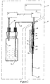
- FIG. 2 shows, in more detail, the dispenser 10 and the control cabinet 14.
- the dispenser 10 includes a support 34 intended to be fixed on the carriage 26 and carrying an elongated body 36, advantageously made of plastic chemically inert, such as the material known as PEEK, generally cylindrical in shape and mounted vertically. It includes, at each end, a cylindrical housing 38 and, in its middle portion, a cavity 40. Furthermore, it is pierced, along its axis, with an upper duct 42 opening, on the one hand, into the upper housing 38 and, on the other hand, into the cavity 40 and a lower duct 44 opening, on the one hand, into the housing lower 38 and, on the other hand, in the cavity 40.
- PEEK plastic chemically inert
- the cavity 40 receives a flow meter 46, produced on a ceramic plate and which is positioned so as to be in sealed communication with the ends of the conduits 42 and 44. It is advantageously fixed by tightening, with interposition of seals.
- the upper housing 38 receives, in a sealed and removable manner, by through an appropriate adapter, a valve 48 having the function ensuring the communication of the upper conduit 42 with the tube 16.
- the lower housing 38 also receives waterproof and removable, using an appropriate adapter, the end of the dispensing needle 12.
- the needle 12 is chosen according to the way in which the fluid 30 must be dispensed on target 32 and the volume to be dispensed, as will be specified further.
- the material constituting the needle 12 must not react with the fluid.
- steel stainless can, for example, be used in many cases.
- the material base may or may not be covered with a layer improving the properties of wettability or non-wettability of certain internal or external surfaces of the needle.
- the length and diameter of the needle hole 12 are chosen according to the amount of fluid to be dispensed at one or more times to target 32. These dimensions are defined so that the volume of the needle hole is greater than the volume of fluid to be dispensed at one time. It is so possible to vacuum the volume in question so that it is fully housed in the needle, which has different advantages.
- the flow meter 46 plays an important role in the proper functioning of the device because it must enable precise measurement of a volume of a few nanoliters. It is advantageous to use, for this purpose, the flowmeter described in the publication "A Differential Pressure Liquid Flow Sensor for Flow Regulation and Dosing Systems ", M. A. Boillat et al. 0-7803-2503-6 ⁇ 1995 IEEE.
- This flow meter includes sensors for measuring a pressure difference between its inlet and outlet, as well as the temperature of fluid flowing through it. These two parameters being determined, it is possible to calculate the flow rate, provided that the viscosity of the transport according to its temperature is known.
- control cabinet 14 includes a sealed container 50 partially filled with a carrier liquid 52 in which immerses the tube 16 connected to the valve 48.
- a pump 54 of the suction type and repressor, is in communication, by a conduit 56, with the part top of container located above liquid 52.
- the liquid 52 is chosen according to the fluid 30 to be dispensed, so that that they are chemically neutral to each other. We note that the liquid 52 fills the tube 16 and passes through the dispenser 10 up to needle 12, as will be explained later.
- the pump 54 enables the container 50 to be overpressured or underpressured. In this way, when the valve 48 is open, the liquid 52 can get move from container 50 to needle 12 or the other way.
- the computer 60 is used for programming and coordinating the assembly. he thus controls the movements of the robot 20 so that the dispenser 10 goes to get doses of fluid 30 in the source 28 then deposits them on target 32.
- it contains in its memory the values of the viscosity of the transport liquid as a function of the temperature. It him allows, from the pressure and temperature information delivered by the flowmeter 46, to determine, with precision and in real time, the quantity of fluid drawn in or discharged through the needle 12. It is thus possible to keep in memory the exact quantities of fluid 30 dispensed each time.
- the analysis of the signals emitted by the flow meter 46 makes it possible to detect malfunctions in the device, such as leakage problem or obturation of conduits 42 or 44.
- the device which has just been described makes it possible to transfer a fluid 30 between the source 28 and target 32 particularly efficiently and economically. This is done as follows.
- the carrier liquid 52 is introduced into the container 50. Then this is closed and the pump 54 is activated, so as to put the container 46 under pressure.
- the valve 48 is then open, so that the liquid 52 enters the tube 16 and passes through the dispenser 10 up to needle 12 which it completely fills. The valve 48 is then closed.
- the device 10 is now ready to take the fluid 30 from the source 28 to deliver it to the target 32.
- the container 50 is pressurized by the pump 54 and the robot 20 brings the needle 12 above the source 28.
- a small amount of air is, first of all, sucked up by needle 12 so as to form a bubble between the liquid 52 and fluid 30 to be dispensed.
- the valve 48 is open and the liquid 52 rises in the needle 12 in the direction of the container 50, through the flowmeter 46 whose output signal allows the control circuit 58 to calculate the volume of air drawn in, i.e. the volume of the bubble.
- the valve 48 is closed and the robot 20 introduces the needle 12 into the fluid 30.
- the flowmeter 46 registers a sudden change in pressure when the needle 12 enters it.
- the computer 60 can thus know the position of the needle 12 by relative to the surface of the fluid 30. It then gives the robot 20 the order to dive needle 12 in fluid 30 enough to prevent bubbles parasites are not formed during aspiration. The valve is then re-opened so as to start aspiration.
- the computer 60 determines that the desired amount of fluid has been drawn into the needle 12, the valve 48 is closed.
- the needle 12 can contain several doses of fluid 30, each separated by a bubble air.
- the fluid 30 can be sucked in without interposing an air bubble.
- the needle 12 is then directly immersed in the fluid 26 and the determination of the aspirated volume is done as described above, but all at once.
- the robot 20 brings the dispenser 10 above target 32 and pump 54 puts container 50 overpressure.
- the valve 48 is then open to let the fluid eject and closed when the measured volume corresponds to the volume set by the computer.
- the dimensions of the needle hole play an important role, especially when the end of it is in the air. In this case, an exemption precise can only be done insofar as the fluid 30 flows from regular way. That is to say that we must avoid drops form during the dispensation operation. An adequate choice of pressure in the container 50 and the diameter of the free end of the needle 12 allows to ensure satisfactory operation.
- the device according to the invention can be used in other conditions again. It is thus also possible to dispense a gas.
- the needle is introduced into a sealed bottle, acting as a source 24, which contains gas and liquid. A volume of gas is drawn in, as explained above about air, then a drop of liquid, so that the gas is trapped in the needle, by successive bubbles of adjusted volume.
- This gas is then dispensed into a target, by injection into it of a volume corresponding to that of the gas and the drop separating two bubbles successive.
Abstract
Description
La présente invention se rapporte aux dispositifs dispensateurs de fluide. Elle concerne, plus particulièrement, un dispositif destiné à délivrer de très faibles volumes, typiquement, de 0,001 à quelques µl, avec une grande précision.The present invention relates to fluid dispensing devices. She relates more particularly to a device intended to deliver very weak volumes, typically, from 0.001 to a few µl, with great precision.
Un tel dispositif est décrit dans le brevet US 5,916,524. Il comprend une aiguille permettant de dispenser un liquide dans une cible et reliée à un ensemble comportant:
- une seringue formant logement et munie d'un piston actionné par un moteur pas à pas,
- un tube reliant la seringue à l'aiguille, et
- un ensemble de vannes associé au tube et permettant, dans un premier temps, de remplir la seringue à partir d'un récipient puis, dans un second temps, de commander l'écoulement du liquide au travers du tube, vers l'aiguille, la quantité dispensée étant définie par le nombre de pas effectués par le moteur pas à pas.
- a syringe forming a housing and provided with a piston actuated by a stepping motor,
- a tube connecting the syringe to the needle, and
- a set of valves associated with the tube and making it possible, firstly, to fill the syringe from a container then, secondly, to control the flow of the liquid through the tube, towards the needle, the quantity dispensed being defined by the number of steps taken by the stepper motor.
Dans la plupart des applications, le liquide à dispenser doit être très pur. Il est, en conséquence, coûteux et délicat à manipuler. De plus, les quantités nécessaires peuvent être extrêmement faibles. Or, avec le dispositif décrit ci-dessus le liquide passe du récipient dans la seringue, puis de celle-ci dans l'aiguille, au travers du tube et des vannes. Le volume ainsi mis en jeu et le risque de pollution sont grands. Par ailleurs, il est difficile de maítriser la quantité dispensée. En effet, le volume de liquide compris entre la seringue et l'extrémité de l'aiguille est important et peut varier de manière sensible, notamment par déformation du tube lorsque celui-ci est souple.In most applications, the liquid to be dispensed should be very pure. It is, as a result, expensive and difficult to handle. In addition, the quantities required may be extremely small. Now, with the device described above the liquid passes from the container into the syringe, then from the latter into the needle, through the tube and the valves. The volume thus involved and the risk of pollution are great. In addition, it is difficult to control the quantity dispensed. Indeed, the volume of liquid between the syringe and the tip of the needle is important and can vary significantly, in particular by deformation of the tube when the latter is flexible.
Un autre dispositif, similaire, est décrit dans le brevet US 5,927,547. Il comporte:
- un dispensateur formé d'un micro-doseur piézo-électrique,
- une seringue munie d'un piston et formant logement, commandée par un moteur pas à pas,
- un capteur de pression, et
- des premier et second tubes reliant respectivement la seringue au capteur et le capteur au micro-doseur.
- a dispenser formed by a piezoelectric micro-metering device,
- a syringe fitted with a piston and forming a housing, controlled by a stepping motor,
- a pressure sensor, and
- first and second tubes respectively connecting the syringe to the sensor and the sensor to the micro-doser.
Dans ce dispositif, la seringue, le capteur et le premier tube, ainsi qu'une partie du second tube, contiennent un liquide transporteur. Un fluide à dispenser, en l'occurrence un liquide également, disposé dans une source, est aspiré par le piston dans le micro-doseur et jusque dans le second tube, avec interposition d'une bulle d'air entre le liquide transporteur et le fluide.In this device, the syringe, the sensor and the first tube, as well as a part of the second tube, contain a carrier liquid. A fluid to dispense, in this case also a liquid, disposed in a source, is sucked by the piston in the micro-doser and into the second tube, with interposition of an air bubble between the carrier liquid and the fluid.
Le fluide à dispenser est éjecté du micro-doseur en appliquant un signal au piézo-électrique, ce qui engendre une onde de choc provoquant l'émission d'une gouttelette de volume connu, fonction des dimensions du micro-doseur et des caractéristiques du fluide considéré.The fluid to be dispensed is ejected from the micro-doser by applying a signal to the piezoelectric, which generates a shock wave causing emission a droplet of known volume, depending on the dimensions of the micro-doser and characteristics of the fluid considered.
Des moyens de commande vérifient, par l'intermédiaire du capteur, que la pression du liquide de transport reste constante, ce qui assure le bon fonctionnement du micro-doseur. Cette pression est ajustée par l'envoi d'impulsions au moteur pas à pas, qui commande le piston de la seringue. Afin de ne dispenser de fluide que dans des cibles chargées, le micro-doseur comporte, à son extrémité libre, un senseur capacitif de niveau.Control means verify, via the sensor, that the pressure of the transport liquid remains constant, which ensures good micro-doser operation. This pressure is adjusted by sending of pulses to the stepper motor, which controls the plunger of the syringe. In order to dispense fluid only in loaded targets, the micro-doser has a capacitive level sensor at its free end.
Le micro-doseur piézo-électrique permet de délivrer des volumes très faibles, pouvant être de l'ordre de 5 picolitres. Le débit maximum atteignable est malheureusement limité, de sorte que le temps nécessaire à dispenser des quantités de liquide de l'ordre du µl rend un tel dispositif peu performant. De plus, le volume disponible dans le micro-doseur est relativement modeste, de sorte que, si l'on veut éviter de trop nombreux mouvements entre la source et la cible, le fluide à dispenser doit être chargé non seulement dans le micro-doseur, mais encore dans le tube qui le relie au capteur. Il y a donc aussi un certain risque de pollution.The piezoelectric micro-metering device enables very low volumes to be delivered, can be of the order of 5 picoliters. The maximum achievable flow is unfortunately limited, so that the time required to dispense quantities of liquid of the order of µl makes such a device ineffective. Of more, the volume available in the micro-doser is relatively modest, from so that if we want to avoid too many movements between the source and the target, the fluid to be dispensed must be loaded not only into the micro-doser, but still in the tube which connects it to the sensor. So there is also a some risk of pollution.
La présente invention a pour but de proposer un dispositif dispensateur sûr et rapide. Ce but est atteint grâce au fait qu'il comporte:
- un organe de dispense comprenant:
- un conduit pour le passage d'un liquide transporteur,
- une vanne fixée à l'une de ses extrémités,
- une aiguille dispensatrice disposée à son autre extrémité,
- des moyens de mesure du débit du liquide transporteur dans le conduit,
- des moyens de commande pour faire circuler ledit liquide au travers dudit conduit dans un sens ou dans l'autre, et
- des moyens électroniques répondant auxdits moyens de mesure et agissant à la fois sur ladite vanne et sur lesdits moyens de commande pour réaliser l'aspiration par l'aiguille, puis sa restitution, d'une quantité déterminée de fluide.
- a dispensing body comprising:
- a conduit for the passage of a carrier liquid,
- a valve fixed at one of its ends,
- a dispensing needle disposed at its other end,
- means for measuring the flow rate of the carrier liquid in the conduit,
- control means for circulating said liquid through said conduit in one direction or the other, and
- electronic means responding to said measuring means and acting both on said valve and on said control means to carry out the aspiration by the needle, then its restitution, of a determined quantity of fluid.
De façon avantageuse, le conduit est formé à l'intérieur d'un corps allongé portant, à ses extrémités respectives, la vanne et l'aiguille et, dans sa portion médiane, les moyens de mesure du débit qui sont interposés sur le trajet du conduit, en communication avec lui. La mesure du volume dispensé est ainsi optimale.Advantageously, the conduit is formed inside an elongated body bearing, at its respective ends, the valve and the needle and, in its portion median, the flow measurement means which are interposed on the path of the leads, in communication with him. The measurement of the volume dispensed is thus optimal.
Pour certaines applications, dans lesquelles de très faibles volumes sont mis en oeuvre, la pratique a montré qu'il est avantageux que le conduit soit formé à l'intérieur d'un corps allongé portant, à ses extrémités respectives, la vanne et l'aiguille et que les moyens de mesure du débit soient interposés sur le trajet du conduit, en amont de la vanne.For some applications, in which very small volumes are put in practice, practice has shown that it is advantageous for the conduit to be formed inside an elongated body carrying, at its respective ends, the valve and the needle and that the flow measurement means are interposed on the path of the conduit, upstream of the valve.
Selon un mode de réalisation préféré, les moyens de mesure du débit sont du type fournissant une mesure de la différence de pression entre deux points du conduit et une mesure de la température.According to a preferred embodiment, the means for measuring the flow are of the type providing a measure of the pressure difference between two points in the duct and a temperature measurement.
Dans ce mode de réalisation, les moyens électroniques peuvent être agencés pour analyser les informations provenant des moyens de mesure du débit et pour informer des conditions de dispense dudit fluide.In this embodiment, the electronic means can be arranged to analyze the information from the flow measurement means and to inform about the conditions for dispensing said fluid.
Les moyens de commande comportent, avantageusement:
- un récipient étanche partiellement rempli du liquide transporteur dans lequel plonge un tube relié à la vanne, et
- une pompe, de type aspirante et refoulante, en communication avec la partie du récipient située au-dessus du liquide.
- a sealed container partially filled with the transporting liquid into which a tube connected to the valve is immersed, and
- a pump, of the suction and discharge type, in communication with the part of the container situated above the liquid.
Dans le présent document, on appelle pompe tout dispositif permettant d'engendrer une sur-pression ou une sous-pression dans le récipient.In this document, pump means any device allowing to create an overpressure or an underpressure in the container.
Les moyens électroniques comportent:
- des moyens de calcul de la quantité de fluide aspiré ou refoulé au travers de l'aiguille, à partir des informations fournies par les moyens de mesure du débit, et
- un circuit de commande placé sous les ordres desdits moyens de calcul et assurant principalement les fonctions de commande de la pompe pour mettre ledit récipient en sur-pression ou en sous-pression et de commande de l'ouverture et de la fermeture de la vanne pour permettre ou non le déplacement d'une quantité déterminée de liquide de transport dans un sens ou dans l'autre.
- means for calculating the quantity of fluid drawn in or discharged through the needle, from information supplied by the flow measurement means, and
- a control circuit placed under the orders of said calculation means and mainly ensuring the pump control functions to put said container under pressure or under pressure and for controlling the opening and closing of the valve for allow or not the movement of a given quantity of transport liquid in one direction or the other.
De préférence, les moyens de calcul ont en mémoire les valeurs de la viscosité du liquide de transport en fonction de la température et sont programmés pour calculer avec précision, à partir des informations de pression et de température livrées par lesdits moyens de mesure du débit, la quantité de fluide aspiré ou refoulé au travers de l'aiguille.Preferably, the calculation means have in memory the values of the viscosity of the transport liquid as a function of temperature and are programmed to calculate accurately, based on information from pressure and temperature delivered by said flow measurement means, the amount of fluid drawn in or discharged through the needle.
Il est intéressant de relever que le dispositif tel que défini ci-dessus permet de mesurer de manière précise le volume de fluide tant lorsqu'il est aspiré que lorsqu'il est dispensé. Il est ainsi possible de préparer des doses d'un ou de plusieurs fluides, séparées par une bulle d'air, ces doses étant ensuite dispensées dans les cibles.It is interesting to note that the device as defined above makes it possible to accurately measure the volume of fluid both when aspirated and when it is dispensed. It is thus possible to prepare doses of one or several fluids, separated by an air bubble, these doses then being dispensed in targets.
D'autres avantages et caractéristiques de l'invention ressortiront de la description qui va suivre, faite en regard du dessin annexé, dans lequel:
- la figure 1 est un schéma de principe d'un dispositif dispensateur de fluide dans son environnement, et
- FIG. 1 is a block diagram of a device for dispensing fluid in its environment, and
La figure 1 montre, de manière schématique, un ensemble comprenant un
dispensateur de fluide 10 équipé d'une aiguille de dispense 12 et une armoire
de commande 14. Un tube 16 et un câble 18 relient le dispensateur 10 à
l'armoire 14.Figure 1 shows, schematically, an assembly comprising a
L'ensemble comprend, en outre, un robot 20 de type cartésien, formé d'une
table horizontale 22, d'un portique 24 monté mobile en translation sur la table
selon une direction perpendiculaire au plan de la figure et d'un chariot 26
monté mobile en translation horizontale sur le portique selon une direction
parallèle au plan de la figure. Le dispensateur 10 est monté mobile en
translation verticale sur le chariot 26, de telle sorte qu'il peut se déplacer ainsi
selon trois axes orthogonaux. Une source 28 contenant un fluide 30, et une
cible 32 sont disposées sur la table 22, dans l'espace balayé par le portique
24.The assembly further comprises a
L'ensemble représenté à la figure 1 est destiné à permettre un transfert précis
du fluide 30, au moyen du dispensateur 10, de la source 28 vers la cible 32.The assembly shown in Figure 1 is intended to allow
Tant la source 28 que la cible 32 peuvent être une éprouvette, une plaque de
micro-titration (de type 96, 384 ou 1536 par exemple) ou toute autre surface
ou réservoir de liquide disposé sur n'importe quel format spatial. Le fluide 30
est généralement un liquide, mais il pourrait également s'agir d'un gaz. Dans
ce cas, la source 28 est un récipient étanche fermé par une membrane
susceptible d'être perforée et l'aiguille 12 est de type similaire à celles
utilisées pour les injections hypodermiques, par exemple.Both the
On se référera maintenant à la figure 2 qui montre, de manière plus détaillée,
le dispensateur 10 et l'armoire de commande 14.We will now refer to FIG. 2 which shows, in more detail,
the
Le dispensateur 10 comprend un support 34 destiné à être fixé sur le chariot
26 et portant un corps allongé 36, avantageusement réalisé en plastique
chimiquement inerte, tel que le matériau connu sous le nom de PEEK, de
forme généralement cylindrique et monté verticalement. Il comporte, à chaque
extrémité, un logement cylindrique 38 et, dans sa portion médiane, une cavité
40. Par ailleurs, il est percé, selon son axe, d'un conduit supérieur 42
débouchant, d'une part, dans le logement supérieur 38 et, d'autre part, dans la
cavité 40 et d'un conduit inférieur 44 débouchant, d'une part, dans le logement
inférieur 38 et, d'autre part, dans la cavité 40.The
La cavité 40 reçoit un débitmètre 46, réalisé sur une plaquette en céramique
et qui est positionné de manière à se trouver en communication étanche avec
les extrémités des conduits 42 et 44. Il est avantageusement fixé par serrage,
avec interposition de joints d'étanchéité.The
Le logement supérieur 38 reçoit, de manière étanche et amovible, par
l'intermédiaire d'un adaptateur approprié, une vanne 48 ayant pour fonction
d'assurer la mise en communication du conduit supérieur 42 avec le tube 16.The
A l'autre extrémité du corps 36, le logement inférieur 38 reçoit, également de
manière étanche et amovible, par l'intermédiaire d'un adaptateur approprié,
l'extrémité de l'aiguille de dispense 12.At the other end of the
L'aiguille 12 est choisie en fonction de la manière dont le fluide 30 doit être
dispensé sur la cible 32 et du volume à dispenser, comme cela sera précisé
plus loin.The
Le matériau constituant l'aiguille 12 ne doit pas réagir avec le fluide. L'acier
inoxydable peut, par exemple, être utilisé dans de nombreux cas. Le matériau
de base peut ou non être recouvert d'une couche améliorant les propriétés de
mouillabilité ou de non-mouillabilité de certaines surfaces internes ou externes
de l'aiguille.The material constituting the
La longueur et le diamètre du trou de l'aiguille 12 sont choisis en fonction de la
quantité de fluide à dispenser en une ou plusieurs fois sur la cible 32. Ces
dimensions sont définies de manière à ce que le volume du trou de l'aiguille
soit plus grand que le volume de fluide à dispenser en une fois. Il est ainsi
possible d'aspirer le volume considéré de manière qu'il soit entièrement logé
dans l'aiguille, ce qui présente différents avantages. The length and diameter of the
En effet, dès lors que le fluide 30 reste confiné dans l'aiguille 12, il suffit de
changer cette dernière lorsqu'on veut dispenser un autre fluide, plutôt que de
devoir nettoyer tout le dispensateur. Il est ainsi possible de dispenser, au
cours d'une même séquence, plusieurs fluides, en des quantités très
variables, sans que cela ne pose problème. Il suffit, à cet effet, de changer
d'aiguille, ce qu'un robot peut faire sans difficulté.Indeed, as soon as the fluid 30 remains confined in the
Il est aussi possible de dispenser des fluides très corrosifs, moyennant simplement le choix de l'aiguille adéquate.It is also possible to dispense very corrosive fluids, provided that simply choosing the right needle.
En d'autres termes, ces avantages proviennent du fait qu'il n'y a pas
d'interférence entre le ou les fluides à dispenser et les composants du
dispensateur 10 autres que l'aiguille 12.In other words, these benefits come from the fact that there is no
of interference between the fluid (s) to be dispensed and the components of the
Le débitmètre 46 joue un rôle important dans le bon fonctionnement du
dispositif car il doit permettre de mesurer, avec précision, un volume de
quelques nanolitres. Il est avantageux d'utiliser, à cet effet, le débitmètre décrit
dans la publication intitulée "A Differential Pressure Liquid Flow Sensor for
Flow Regulation and Dosing Systems", M. A. Boillat et al. 0-7803-2503-6 ©
1995 IEEE. Ce débitmètre comporte des capteurs permettant de mesurer une
différence de pression entre son entrée et sa sortie, ainsi que la température
du fluide qui le traverse. Ces deux paramètres étant déterminés, il est
possible de calculer le débit, à condition que la viscosité du liquide de
transport en fonction de sa température soit connue.The
Comme le montre la figure 2, l'armoire de commande 14 comprend un
récipient étanche 50 partiellement rempli d'un liquide transporteur 52 dans
lequel plonge le tube 16 relié à la vanne 48. Une pompe 54, de type aspirante
et refoulante, est en communication, par un conduit 56, avec la partie
supérieure du récipient située au-dessus du liquide 52.As shown in Figure 2, the
Le liquide 52 est choisi en fonction du fluide 30 à dispenser, de manière à ce
qu'ils soient, du point de vue chimique, neutres l'un à l'égard de l'autre. On
notera que le liquide 52 remplit le tube 16 et traverse le dispensateur 10
jusqu'à l'aiguille 12, comme cela sera précisé plus loin. The liquid 52 is chosen according to the fluid 30 to be dispensed, so that
that they are chemically neutral to each other. We
note that the liquid 52 fills the
La pompe 54 permet de mettre le récipient 50 en sur-pression ou en sous-pression.
De la sorte, lorsque la vanne 48 est ouverte, le liquide 52 peut se
déplacer du récipient 50 vers l'aiguille 12 ou dans l'autre sens.The
Un circuit de commande 58 est relié à la pompe 54, à la vanne 48 et au débitmètre 46. Il est sous les ordres d'un ordinateur 60 afin d'assurer les principales fonctions suivantes:
- commande de la pompe 54 en vue de mettre le récipient 50 en sur-pression ou en sous-pression,
- commande de l'ouverture et de la fermeture de la vanne 48, permettant ou non le déplacement du liquide 52 dans un sens ou dans l'autre,
- transmission à l'ordinateur 60 des mesures de pression et de température provenant du débitmètre 46.
- control of the
pump 54 with a view to placing thecontainer 50 under pressure or under pressure, - control of the opening and closing of the
valve 48, allowing or not the displacement of the liquid 52 in one direction or the other, - transmission to the
computer 60 of the pressure and temperature measurements coming from theflow meter 46.
L'ordinateur 60 sert à la programmation et à la coordination de l'ensemble. Il
contrôle ainsi les déplacements du robot 20 de manière à ce que le
dispensateur 10 aille chercher des doses de fluide 30 dans la source 28 puis
les dépose sur la cible 32. De plus, il contient dans sa mémoire les valeurs de
la viscosité du liquide de transport en fonction de la température. Cela lui
permet, à partir des informations de pression et de température livrées par le
débitmètre 46, de déterminer, avec précision et en temps réel, la quantité de
fluide aspiré ou refoulé au travers de l'aiguille12. Il est ainsi possible de garder
en mémoire les quantités exactes de fluide 30 dispensées à chaque fois. En
outre, l'analyse des signaux émis par le débitmètre 46 permet de détecter des
disfonctionnements dans le dispositif, tels que problème d'étanchéité ou
obturation des conduits 42 ou 44.The
Le dispositif qui vient d'être décrit permet de transférer un fluide 30 entre la
source 28 et la cible 32 de manière particulièrement efficace et économique.
Cette opération s'effectue de la manière suivante.The device which has just been described makes it possible to transfer a fluid 30 between the
Dans un premier temps, le liquide transporteur 52 est introduit dans le
récipient 50. Puis celui-ci est fermé et la pompe 54 est activée, de manière à
mettre le récipient 46 en sur-pression. La vanne 48 est alors ouverte, de sorte
que le liquide 52 pénètre dans le tube 16 et traverse le dispensateur 10
jusqu'à l'aiguille 12 qu'il remplit complètement. La vanne 48 est alors fermée.Firstly, the
Lors de cette opération, il est indispensable de s'assurer qu'il ne reste pas de
bulle d'air dans le tube 16, ce qui dégraderait les performances du dispositif.
Cette vérification peut se faire de manière automatique, par l'analyse des
signaux émis par le débitmètre. On constate en effet que la présence de
bulles d'air amène une élasticité dans les conduits 42 et 44, ce qui ralentit la
montée en pression lorsque la vanne est ouverte.During this operation, it is essential to ensure that there are no
air bubble in the
Le dispositif 10 est maintenant prêt à prélever le fluide 30 dans la source 28
pour le dispenser sur la cible 32. A cet effet, le récipient 50 est mis en sous-pression
par la pompe 54 et le robot 20 amène l'aiguille 12 au-dessus de la
source 28.The
Selon un mode de fonctionnement avantageux, une faible quantité d'air est,
tout d'abord, aspirée par l'aiguille 12 de manière à former une bulle entre le
liquide 52 et le fluide 30 à dispenser. A cet effet, la vanne 48 est ouverte et le
liquide 52 remonte dans l'aiguille 12 en direction du récipient 50, au travers du
débitmètre 46 dont le signal de sortie permet au circuit de commande 58 de
calculer le volume d'air aspiré, c'est à dire le volume de la bulle. Lorsque le
volume mesuré atteint la valeur désirée, contenue dans l'ordinateur 60, la
vanne 48 est fermée et le robot 20 introduit l'aiguille 12 dans le fluide 30.According to an advantageous operating mode, a small amount of air is,
first of all, sucked up by
Lorsque ce dernier est un liquide, ce qui est généralement le cas, le
débitmètre 46 enregistre une brusque variation de pression quand l'aiguille 12
y pénètre. L'ordinateur 60 peut ainsi connaítre la position de l'aiguille 12 par
rapport à la surface du fluide 30. Il donne alors au robot 20 l'ordre de plonger
l'aiguille 12 dans le fluide 30 suffisamment pour éviter que des bulles
parasites ne se forment lors de l'aspiration. La vanne est ensuite ré-ouverte
de manière à commencer l'aspiration.When the latter is a liquid, which is generally the case, the
Lorsque, sur la base des indications fournies par le débitmètre 46, l'ordinateur
60 détermine que la quantité souhaitée de fluide a été aspirée dans l'aiguille
12, la vanne 48 est refermée. When, on the basis of the indications provided by the
Il est possible de répéter cette opération plusieurs fois, de sorte que l'aiguille
12 peut contenir plusieurs doses du fluide 30, séparées chacune par une bulle
d'air.It is possible to repeat this operation several times, so that the
En variante, le fluide 30 peut être aspiré sans interposition d'une bulle d'air.
L'aiguille 12 est alors directement plongée dans le fluide 26 et la détermination
du volume aspiré se fait comme décrit ci-dessus, mais en une seule fois.Alternatively, the fluid 30 can be sucked in without interposing an air bubble.
The
Lorsque l'aiguille 12 est chargée du fluide à dispenser, le robot 20 amène le
dispensateur 10 au-dessus de la cible 32 et la pompe 54 met le récipient 50
en sur-pression. La vanne 48 est alors ouverte pour laisser éjecter le fluide et
refermée lorsque le volume mesuré correspond au volume fixé par
l'ordinateur.When the
Les dimensions du trou de l'aiguilles jouent un rôle important, spécialement
lorsque l'extrémité de celle-ci se trouve dans l'air. Dans ce cas, une dispense
précise ne peut se faire que dans la mesure où le fluide 30 s'écoule de
manière réguliaire. Cela revient à dire qu'il faut éviter que des gouttes se
forment lors de l'opération de dispense. Un choix adéquat de la pression dans
le récipient 50 et du diamètre de l'extrémité libre de l'aiguille 12 permet
d'assurer un fonctionnement satisfaisant.The dimensions of the needle hole play an important role, especially
when the end of it is in the air. In this case, an exemption
precise can only be done insofar as the fluid 30 flows from
regular way. That is to say that we must avoid drops
form during the dispensation operation. An adequate choice of pressure in
the
Lorsqu'un faible volume doit être dispensé, il est avantageux d'utiliser une
aiguille comportant un rétrécissement du trou à son extrémité libre, bien
connue sous le nom anglais de "nozzle". Il est, en outre, alors avantageux que
le débitmètre 46 se trouve en amont de la vanne 48. L'expérience a en effet
montré qu'ainsi l'écoulement pouvait être bien maítrisé, même avec de faibles
débits.When a small volume has to be dispensed, it is advantageous to use a
needle with a narrowing of the hole at its free end, well
known by the English name "nozzle". It is further advantageous that
the
Il va de soi que le dispositif selon l'invention peut être utilisé dans d'autres
conditions encore. Il est ainsi aussi possible de dispenser un gaz. Dans ce
cas, l'aiguille est introduite dans un flacon étanche, tenant lieu de source 24,
qui contient le gaz et du liquide. Un volume de gaz est aspiré, comme
expliqué plus haut à propos de l'air, puis une goutte de liquide, de sorte que le
gaz est emprisonné dans l'aiguille, par bulles successives de volume ajusté. It goes without saying that the device according to the invention can be used in other
conditions again. It is thus also possible to dispense a gas. In this
case, the needle is introduced into a sealed bottle, acting as a
Ce gaz est, ensuite, dispensé dans une cible, par injection dans celle-ci d'un volume correspondant à celui du gaz et de la goutte séparant deux bulles successives.This gas is then dispensed into a target, by injection into it of a volume corresponding to that of the gas and the drop separating two bubbles successive.
Claims (8)
Priority Applications (6)
| Application Number | Priority Date | Filing Date | Title |
|---|---|---|---|
| EP00810970A EP1207396A1 (en) | 2000-10-20 | 2000-10-20 | Fluid dispenser |
| AT01973940T ATE423323T1 (en) | 2000-10-20 | 2001-10-12 | DEVICE FOR DISPENSING LIQUID |
| DE60137700T DE60137700D1 (en) | 2000-10-20 | 2001-10-12 | DEVICE FOR DELIVERING LIQUID |
| EP01973940A EP1327152B1 (en) | 2000-10-20 | 2001-10-12 | Fluid dispensing device |
| PCT/CH2001/000614 WO2002033423A1 (en) | 2000-10-20 | 2001-10-12 | Fluid dispensing device |
| US10/399,583 US7303728B2 (en) | 2000-10-20 | 2001-10-12 | Fluid dispensing device |
Applications Claiming Priority (1)
| Application Number | Priority Date | Filing Date | Title |
|---|---|---|---|
| EP00810970A EP1207396A1 (en) | 2000-10-20 | 2000-10-20 | Fluid dispenser |
Publications (1)
| Publication Number | Publication Date |
|---|---|
| EP1207396A1 true EP1207396A1 (en) | 2002-05-22 |
Family
ID=8174981
Family Applications (2)
| Application Number | Title | Priority Date | Filing Date |
|---|---|---|---|
| EP00810970A Withdrawn EP1207396A1 (en) | 2000-10-20 | 2000-10-20 | Fluid dispenser |
| EP01973940A Expired - Lifetime EP1327152B1 (en) | 2000-10-20 | 2001-10-12 | Fluid dispensing device |
Family Applications After (1)
| Application Number | Title | Priority Date | Filing Date |
|---|---|---|---|
| EP01973940A Expired - Lifetime EP1327152B1 (en) | 2000-10-20 | 2001-10-12 | Fluid dispensing device |
Country Status (5)
| Country | Link |
|---|---|
| US (1) | US7303728B2 (en) |
| EP (2) | EP1207396A1 (en) |
| AT (1) | ATE423323T1 (en) |
| DE (1) | DE60137700D1 (en) |
| WO (1) | WO2002033423A1 (en) |
Cited By (2)
| Publication number | Priority date | Publication date | Assignee | Title |
|---|---|---|---|---|
| DE102007019186A1 (en) | 2007-04-20 | 2008-10-30 | Qiagen Instruments Ag | Pipetting device and method |
| US7964160B2 (en) | 2005-07-22 | 2011-06-21 | Tecan Trading Ag | Pipetting apparatus with a computer program product and a method for accepting or rejecting pipetted liquid samples |
Families Citing this family (17)
| Publication number | Priority date | Publication date | Assignee | Title |
|---|---|---|---|---|
| US7073442B2 (en) * | 2002-07-03 | 2006-07-11 | Afbs, Inc. | Apparatus, systems and methods for use in three-dimensional printing |
| DE10255595A1 (en) * | 2002-11-26 | 2004-06-03 | Cybio Ag | Multi-channel dosing device with automatic calibration |
| US7640787B2 (en) * | 2004-02-06 | 2010-01-05 | Seyonic S.A. | Pipette verification device and pipette |
| EP1596169B1 (en) * | 2004-05-14 | 2012-05-30 | F. Hoffmann-La Roche AG | Level sensor apparatus for detecting contact of a pipetting needle with a liquid in a vessel |
| EP1604741A1 (en) * | 2004-05-14 | 2005-12-14 | F. Hoffmann-La Roche Ag | Method and apparatus for dispensing a liquid with a pipetting needle |
| US7479391B2 (en) * | 2004-12-10 | 2009-01-20 | Tecan Trading Ag | Pipetting apparatus with integrated liquid level and/or gas bubble detection |
| US20070025879A1 (en) * | 2005-07-27 | 2007-02-01 | Dakocytomation Denmark A/S | Method and apparatus for syringe-based sample introduction within a flow cytometer |
| US7926325B2 (en) * | 2008-04-23 | 2011-04-19 | Siemens Healthcare Diagnostics Inc. | Differentiating between abnormal sample viscosities and pipette clogging during aspiration |
| CH702769B1 (en) * | 2010-02-22 | 2019-07-31 | Reseachem Gmbh | Metering device and method for metering a fluid into a reaction vessel. |
| EP2489992A1 (en) * | 2011-02-21 | 2012-08-22 | CSEM Centre Suisse d'Electronique et de Microtechnique SA - Recherche et Développement | Liquid metering device |
| EP2818873A1 (en) | 2013-06-24 | 2014-12-31 | Seyonic SA | Method of controlling pipetting operations |
| WO2016149666A1 (en) * | 2015-03-19 | 2016-09-22 | Beckman Coulter, Inc. | Dispenser for an analyzer |
| DE102017216713B4 (en) | 2017-09-21 | 2020-07-30 | Festo Se & Co. Kg | Method and metering device for metered fluid delivery |
| US11320295B2 (en) | 2019-04-26 | 2022-05-03 | Festo Se & Co. Kg | Dosing unit and method for dosing a liquid |
| DE102019119414B3 (en) * | 2019-07-17 | 2020-06-18 | Pilz Gmbh & Co. Kg | Manipulation detection system for a filler neck of a bottling plant and method for detecting manipulation on a filler neck of a bottling plant |
| WO2021023968A1 (en) * | 2019-08-02 | 2021-02-11 | Douglas Scientific, LLC | An aspirate-dispense apparatus and associated methods |
| US20220228202A1 (en) * | 2021-01-20 | 2022-07-21 | Applied Materials, Inc. | Positive pressure driven flow for multiplexed fluorescence in situ hybridization imaging system |
Citations (5)
| Publication number | Priority date | Publication date | Assignee | Title |
|---|---|---|---|---|
| EP0747689A2 (en) * | 1995-06-07 | 1996-12-11 | Medical Laboratory Automation, Inc. | Liquid aspiration from a sealed container |
| EP0865824A1 (en) * | 1997-03-20 | 1998-09-23 | F. Hoffmann-La Roche Ag | Micromechanical pipetting device |
| WO1999020395A1 (en) * | 1997-10-22 | 1999-04-29 | Argonaut Technologies, Inc. | Systems and methods for combinatorial organic synthesis of arrays of reaction |
| US5916524A (en) * | 1997-07-23 | 1999-06-29 | Bio-Dot, Inc. | Dispensing apparatus having improved dynamic range |
| US5927547A (en) * | 1996-05-31 | 1999-07-27 | Packard Instrument Company | System for dispensing microvolume quantities of liquids |
Family Cites Families (5)
| Publication number | Priority date | Publication date | Assignee | Title |
|---|---|---|---|---|
| US5143849A (en) * | 1991-03-21 | 1992-09-01 | Eastman Kodak Company | Tip to surface spacing for optimum dispensing controlled by a detected pressure change in the tip |
| US6203759B1 (en) | 1996-05-31 | 2001-03-20 | Packard Instrument Company | Microvolume liquid handling system |
| EP1007973B1 (en) * | 1997-04-08 | 2004-12-01 | Packard Instrument Company, Inc. | Microvolume liquid handling system |
| DE19722731A1 (en) | 1997-04-10 | 1998-10-15 | Beko Kondensat Technik Gmbh | Compressed air drying membrane filter unit |
| US6190619B1 (en) | 1997-06-11 | 2001-02-20 | Argonaut Technologies, Inc. | Systems and methods for parallel synthesis of compounds |
-
2000
- 2000-10-20 EP EP00810970A patent/EP1207396A1/en not_active Withdrawn
-
2001
- 2001-10-12 US US10/399,583 patent/US7303728B2/en not_active Expired - Fee Related
- 2001-10-12 EP EP01973940A patent/EP1327152B1/en not_active Expired - Lifetime
- 2001-10-12 DE DE60137700T patent/DE60137700D1/en not_active Expired - Lifetime
- 2001-10-12 AT AT01973940T patent/ATE423323T1/en not_active IP Right Cessation
- 2001-10-12 WO PCT/CH2001/000614 patent/WO2002033423A1/en active Application Filing
Patent Citations (5)
| Publication number | Priority date | Publication date | Assignee | Title |
|---|---|---|---|---|
| EP0747689A2 (en) * | 1995-06-07 | 1996-12-11 | Medical Laboratory Automation, Inc. | Liquid aspiration from a sealed container |
| US5927547A (en) * | 1996-05-31 | 1999-07-27 | Packard Instrument Company | System for dispensing microvolume quantities of liquids |
| EP0865824A1 (en) * | 1997-03-20 | 1998-09-23 | F. Hoffmann-La Roche Ag | Micromechanical pipetting device |
| US5916524A (en) * | 1997-07-23 | 1999-06-29 | Bio-Dot, Inc. | Dispensing apparatus having improved dynamic range |
| WO1999020395A1 (en) * | 1997-10-22 | 1999-04-29 | Argonaut Technologies, Inc. | Systems and methods for combinatorial organic synthesis of arrays of reaction |
Non-Patent Citations (1)
| Title |
|---|
| BOILLAT M A ET AL: "A DIFFERENTIAL PRESSURE LIQUID FLOW SENSOR FOR FLOW REGULATION AND DOSING SYSTEMS", PROCEEDINGS OF THE WORKSHOP ON MICRO ELECTRICAL MECHANICAL SYSTEMS. (MEMS),US,NEW YORK, IEEE, vol. WORKSHOP 8, 29 January 1995 (1995-01-29), pages 350 - 352, XP000555295, ISBN: 0-7803-2504-4 * |
Cited By (2)
| Publication number | Priority date | Publication date | Assignee | Title |
|---|---|---|---|---|
| US7964160B2 (en) | 2005-07-22 | 2011-06-21 | Tecan Trading Ag | Pipetting apparatus with a computer program product and a method for accepting or rejecting pipetted liquid samples |
| DE102007019186A1 (en) | 2007-04-20 | 2008-10-30 | Qiagen Instruments Ag | Pipetting device and method |
Also Published As
| Publication number | Publication date |
|---|---|
| US20040020938A1 (en) | 2004-02-05 |
| ATE423323T1 (en) | 2009-03-15 |
| EP1327152B1 (en) | 2009-02-18 |
| WO2002033423A1 (en) | 2002-04-25 |
| DE60137700D1 (en) | 2009-04-02 |
| US7303728B2 (en) | 2007-12-04 |
| EP1327152A1 (en) | 2003-07-16 |
Similar Documents
| Publication | Publication Date | Title |
|---|---|---|
| EP1327152B1 (en) | Fluid dispensing device | |
| EP1066532B1 (en) | Biological sampling method | |
| FR2927999A1 (en) | VISCOSIMETER COMPRISING A PIPETAGE SYSTEM, WITH IMPROVED PRECISION AND SIMPLIFIED DESIGN | |
| WO1998009911A1 (en) | Method, device and installation for dispensing dosed amounts of liquid | |
| EP2255161A1 (en) | Method for measuring dispensed volume of a liquid in a container by measuring capacity | |
| EP1230553B1 (en) | Chemical or biochemical analyser with reaction temperature adjustment | |
| EP0213050A1 (en) | Device for measuring the quantity of an ultrafiltrate withdrawn during a dialysis treatment | |
| EP1361442B1 (en) | method and device for dispensing liquids | |
| WO2007148485A1 (en) | Dispenser unit and analytical instrument | |
| EP3014283A1 (en) | Method for controlling pipetting operations | |
| EP0335789B1 (en) | Simplified automatic blood analysis system | |
| EP0351256B1 (en) | Simplified drawing and discharging device for an automatic blood analysis system | |
| EP0636874B1 (en) | Microdosing method for liquids providing nanovolumetric dilutions | |
| FR2474697A1 (en) | MULTI-POSITION FLUID TRANSFER MECHANISM | |
| FR2827318A1 (en) | Apparatus for evaluating mechanical resistance of soil has probe containing incompressible liquid linked to hollow cylindrical recipient | |
| FR2580396A1 (en) | DEVICE FOR INDICATING AND / OR MEASURING EXTREMELY WEAK MATTER FLOW | |
| EP0357466B1 (en) | Symplified lysis circuit for an automatic blood analysis system | |
| FR2513376A1 (en) | AUTOMATIC PIPETTING DEVICE | |
| FR2822540A1 (en) | Automatic accurate measurement or titration of small volumes of liquid in which small volumes are repeatedly measured in a calibrated measurement volume | |
| FR2568373A1 (en) | Permeameter. | |
| BE649075A (en) | ||
| FR2984767A1 (en) | Installation for proportioning paint on vehicle, has control unit arranged to control series of impulses of ejection opening to obtain series of discontinuous fluid jets, and controlling stopping of series based on fluid mass preset value | |
| FR2596151A1 (en) | Method and device for calibrating a liquid meter | |
| FR2496259A1 (en) | Pipette assembly, esp. for mixing two liquids - where each pipette has level detectors operating solenoid valves used to fill and empty pipettes | |
| FR2763580A1 (en) | Liquid dispensing method for small measured doses of liquid in fine chemical industries |
Legal Events
| Date | Code | Title | Description |
|---|---|---|---|
| PUAI | Public reference made under article 153(3) epc to a published international application that has entered the european phase |
Free format text: ORIGINAL CODE: 0009012 |
|
| AX | Request for extension of the european patent |
Free format text: AL;LT;LV;MK;RO;SI |
|
| AKX | Designation fees paid | ||
| REG | Reference to a national code |
Ref country code: DE Ref legal event code: 8566 |
|
| STAA | Information on the status of an ep patent application or granted ep patent |
Free format text: STATUS: THE APPLICATION IS DEEMED TO BE WITHDRAWN |
|
| 18D | Application deemed to be withdrawn |
Effective date: 20021125 |