EP1202610A2 - Method for driving a sensor controlled lamp - Google Patents
Method for driving a sensor controlled lamp Download PDFInfo
- Publication number
- EP1202610A2 EP1202610A2 EP01117702A EP01117702A EP1202610A2 EP 1202610 A2 EP1202610 A2 EP 1202610A2 EP 01117702 A EP01117702 A EP 01117702A EP 01117702 A EP01117702 A EP 01117702A EP 1202610 A2 EP1202610 A2 EP 1202610A2
- Authority
- EP
- European Patent Office
- Prior art keywords
- sensor
- lamp
- sensor signal
- microprocessor
- switch
- Prior art date
- Legal status (The legal status is an assumption and is not a legal conclusion. Google has not performed a legal analysis and makes no representation as to the accuracy of the status listed.)
- Granted
Links
Images


Classifications
-
- H—ELECTRICITY
- H05—ELECTRIC TECHNIQUES NOT OTHERWISE PROVIDED FOR
- H05B—ELECTRIC HEATING; ELECTRIC LIGHT SOURCES NOT OTHERWISE PROVIDED FOR; CIRCUIT ARRANGEMENTS FOR ELECTRIC LIGHT SOURCES, IN GENERAL
- H05B47/00—Circuit arrangements for operating light sources in general, i.e. where the type of light source is not relevant
- H05B47/10—Controlling the light source
- H05B47/105—Controlling the light source in response to determined parameters
- H05B47/11—Controlling the light source in response to determined parameters by determining the brightness or colour temperature of ambient light
-
- Y—GENERAL TAGGING OF NEW TECHNOLOGICAL DEVELOPMENTS; GENERAL TAGGING OF CROSS-SECTIONAL TECHNOLOGIES SPANNING OVER SEVERAL SECTIONS OF THE IPC; TECHNICAL SUBJECTS COVERED BY FORMER USPC CROSS-REFERENCE ART COLLECTIONS [XRACs] AND DIGESTS
- Y02—TECHNOLOGIES OR APPLICATIONS FOR MITIGATION OR ADAPTATION AGAINST CLIMATE CHANGE
- Y02B—CLIMATE CHANGE MITIGATION TECHNOLOGIES RELATED TO BUILDINGS, e.g. HOUSING, HOUSE APPLIANCES OR RELATED END-USER APPLICATIONS
- Y02B20/00—Energy efficient lighting technologies, e.g. halogen lamps or gas discharge lamps
- Y02B20/40—Control techniques providing energy savings, e.g. smart controller or presence detection
Definitions
- the invention relates to a method for controlling a sensor-controlled Lamp according to the preamble of claim 1 and a Sensor-controlled lamp according to the preamble of patent claim 12.
- a fluorescent lamp is known in which the Control of a ballast for the discharge tube of the fluorescent lamp depending on the signal of a light sensor via which the incidence of light from the surroundings is detected.
- a problem with such fluorescent lamps is that the incidence of Eigenlight is overlaid with the incidence of light from the environment, so that signal detected by the light sensor can be falsified.
- This problem is reinforced by the fact that the spectrum of the discharge vessel emitted light after starting the lamp changed because of the proportion Infrared radiation immediately after starting is relatively high and after one certain start time (burn-in time) drops to a low value.
- this becomes normal Infrared light contained in daylight by the one emitted in the burn-in phase Infrared portion amplified, so that the signal detected by the sensor in the burn-in phase is significantly falsified.
- This falsification of the sensor signal can, for example, cause the fluorescent lamp to start with Reduction of the ambient light starts and then again after the start switches off because the sensors emit a signal due to the infrared component of the natural light detect that the brightness is greater than the actual brightness, so that the fluorescent lamp despite the low incidence of light from the Environment is switched off.
- the object of the invention is a method for controlling a sensor-controlled lamp and a sensor-controlled To create a lamp in which a falsification of the sensor signals due to superimposed interference signals even under unfavorable operating conditions is minimized.
- the lamp is provided with a microprocessor, over which the temporal change of the sensor signal due to the incident Light is detected. Depending on these gradients of the sensor signal can then control parameters for controlling the lamp be determined.
- This concept according to the invention makes it possible for the first time the control of the illuminant depending on the change over time to control the incidence of light so that external influences such as temperature fluctuations Type of covers, sources of interference etc., as well as the burn-in behavior recorded via the gradient and taken into account in the control becomes.
- the control over the time change of the control signal enables it, for example, the reduction of the infrared portion of the natural light to be detected extremely precisely during the burn-in phase, so that the lamp during the stoving phase - regardless of temperature, condition the lamp, the quality of the lamp, the power supply, the Type of lamp cover, mounting position, etc. - operated in one mode no change due to the incident light on the sensor the operating state of the discharge vessel.
- the normal control the lamp only takes place when the infrared portion is in natural light has subsided, so that the change in the sensor signal due to time the relatively constant incidence of light from the surroundings is low. This means, this switchover is no longer dependent on a medium-sized, usual one Operating conditions adapted dead time, but is individual, with each The fluorescent lamp is switched on depending on the operating conditions redefined so that it functions properly the lamp is guaranteed.
- the value falls below a predetermined limit value of the change over time Switch-off or switch-over threshold after each start process fixed by a predetermined value above the size of the sensor signal when the limit value is reached. That is, according to the invention these switch-off or switchover thresholds at each Starting process redetermined, so that a manual adjustment as described above State of the art is not required.
- the lamp can be switched off, for example, because then it can be assumed that there is sufficient daylight.
- Switching off can of course also on other operating conditions, such as for example a power reduction, a flashing, a dimming or similar can be switched.
- Interference signals can also be generated by external ambient light - for example car headlights, Headlights from neighboring buildings etc.- are hidden, since these stray light sources usually with a sudden increase the brightness are connected. That is, from the sudden change of the control signal is concluded on the presence of a stray light and according to the invention switched a dead time that runs until the stray light no longer influences the ambient light. That is, during this dead time the control of the discharge vessel is not changed.
- external ambient light for example car headlights, Headlights from neighboring buildings etc.- are hidden, since these stray light sources usually with a sudden increase the brightness are connected. That is, from the sudden change of the control signal is concluded on the presence of a stray light and according to the invention switched a dead time that runs until the stray light no longer influences the ambient light. That is, during this dead time the control of the discharge vessel is not changed.
- An emergency shutdown can also be specified via the microprocessor Be over which the lamp automatically when a predetermined switches off maximum sensor signals.
- the time recording of the incidence of light via the microprocessor enables it, a light curve depending on a light change cycle, for example, to capture a daily cycle, so that when known Light characteristic from the change in the sensor signal over time Conclusion on the cycle time, for example the time of day is possible.
- the lamp can then function as a function of this determined cycle time to be controlled.
- the fluorescent lamp according to the invention is preferably used with two Sensors executed, the signals of both sensors in the microprocessor processed independently or together.
- the lamp can be made particularly compact if the microprocessor, the sensors and the lamp control (pilot control unit, etc.) a single common board are included.
- the operational safety of the sensor-controlled lamp can be increased if a program for a test cycle is stored in the microprocessor, when the lamp is started up or when it is covered arbitrarily the sensors are passed through.
- the Lamp switched on and off for example after predetermined time intervals be so that the user can easily from the functionality the lamp can convince.
- FIG. 1 shows a schematic illustration of a fluorescent lamp 1.
- This has a discharge vessel 2, the end of which is fastened in a base housing 4 is.
- a screw-in base 6 for screwing in the fluorescent lamp 1 formed in a lamp holder.
- On the outer circumference of the base housing 4 are two diametrically arranged infrared sensors 8, 10 arranged, via which the infrared portion of the incident light can be detected is.
- a circuit board 12 indicated by dash-dotted lines recorded on which the two infrared sensors 8, 10, a microprocessor 14, as well as the usual lamp control, such as the ballast 16 (see Figure 2) added to control the discharge vessel 2 are.
- the Microprocessor 14 due to the time course of the sensors 8, 10 incident light to set and switch certain switching thresholds change and thus an optimal adjustment of the lamp control in Depends on the condition of the lamp, the network and the environmental conditions to ensure.
- Figure 2 shows a highly simplified circuit diagram of the circuit is recorded on the circuit board 12 indicated by dash-dotted lines. Accordingly, becomes the input signal ⁇ of the two corresponding to the incidence of light Sensors 8, 10 are acquired as a function of the measurement time and are acquired from these and stored sensor signals of the gradient d ⁇ / dt. In This then becomes dependent on these time-dependent values ⁇ and d ⁇ / dt Ballast 16 for the discharge vessel 2 controlled to their operating state to change (on / off; dim, blink etc.).
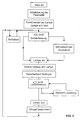
- FIG 3 shows a flow diagram of the program, which is via the microprocessor 14 is controlled.
- the program will start as soon as the Fluorescent lamp 1 is screwed into the lamp holder and a connection to the network. After such initial start-up the fluorescent lamp 1 will first be some for lamp control initialized necessary parameters, for example in memory data stored in the microprocessor 14 are read out or dependent be adjusted by the current incidence of light. This in memory of the microprocessor 14, for example Threshold values for switching the discharge vessel on and off, control times such as a self-test time, as well as maximum times for the detection of operating states (Burn-in time, dead times for blanking out interference signals etc.).
- the normal light detection takes place via the two sensors 8, 10, the sensor signals being time-dependent stored and the aforementioned gradient d ⁇ from the stored values / dt is formed.
- FIG. 4 shows the time course of the sensor signal ⁇ as a function of the time of day t.
- the sensor signal In the event of daylight, the sensor signal is at a high level, which is substantially above a switch-on threshold ⁇ E that was stored during initialization and possibly adapted to the ambient conditions.
- the sensor signal ⁇ becomes weaker and falls below the switch-on thresholds ⁇ E at time t 1 , so that the program recognizes the "dark" ambient state and generates a control signal for switching on the discharge vessel 2.
- the sensor signal ⁇ remains at an approximately constant low level and only rises again in the morning hours when the brightness falls to the threshold value ⁇ E , which it reaches at time t 2 .
- the discharge vessel 2 is switched off.
- the sensor signal ⁇ detected by the sensor when the lamp is switched off increases with increasing brightness until it reaches its maximum level in the midday.
- the lamp is started quickly and the discharge vessel 2 is switched on. If the sensor signal is still in the bright area, the incidence of light and the gradient d ⁇ / dt are recorded at predetermined time intervals and the lamp is switched on when the sensor signal ⁇ falls below the switch-on threshold ⁇ E.
- the gradient is then d ⁇ / dt the burn-in phase of the lamp in the manner described below detected and set a switch-off threshold after the burn-in phase.
- the light detection runs with the evaluation the sensor signals ⁇ and the formation of the gradients d ⁇ / dt.
- a stray light occurs when the discharge vessel 2 is switched on, can be blanked out via the program control via which the influence of the stray light can be compensated for and therefore no influence on the operating state of the discharge vessel.
- lamp 1 After exceeding the set during the program run Switch-off threshold, lamp 1 is switched off and, if necessary, from the figure 3 characteristic curve determines a time that a time-dependent program control allows. Program control then returns to yours Initial state after the initialization of the parameters and the one-off Function tests of the lamp back.
- the fluorescent lamp 2 two sensors 8, 10.
- the sensor signals ⁇ of both signals can (in Microprocessor) separately or after a weighting (average value) processed together.
- the microprocessor control according to the invention makes it possible to identify such sources of error from the gradient d ⁇ / dt and to issue corresponding correction signals to the lamp control. This will be explained with reference to the following figures 5 to 7.
- the characteristic curve shown in FIG. 4 represents an ideal state in which the sensor signal ⁇ is not falsified by interference or an inherent light component. In reality, a sensor signal arises, as shown in FIG. 5. As in the ideal state described above, the sensor signal ⁇ drops during the transition from light to dark to the switch-on threshold ⁇ E , so that the fluorescent lamp 1 is switched on when this switch-on threshold ⁇ E is reached.
- This can be predefined in the memory of the microprocessor, but in principle it is also possible to adapt this switch-on threshold dynamically depending on the characteristic curve shown in FIG. 4, so that seasonal influences, the time of initialization or the location of the lamp can be taken into account.
- the sensor signal ⁇ rises due to the comparatively high infrared portion of the natural light, so that the sensor signal moves back into the bright area.
- the infrared portion of the intrinsic light decreases, so that the sensor signal drops again below the switch-on threshold ⁇ E and, after the lamp has completely burned in, is essentially only determined by the incidence of light from the surroundings.
- the curve shown in FIG. 5 thus results in another overshoot in the bright area and a drop in the sensor signal in the dark area, the end of the burn-in phase being characterized by the transition to the approximately horizontal section of the sensor signal ,
- the burn-in phase can be reliably detected on the basis of the above-described changes in the sensor signal, the controller then reacting to the end of the burn-in phase when the gradient d ⁇ / dt falls below a predetermined limit value E 1 .
- the overshoot of the sensor signal into the bright area is disregarded, so that no control signals are emitted by the microprocessor 14 to switch off the discharge vessel to the ballast 16. The influence of natural light is thus reliably prevented during the burn-in phase.
- the program control sets a switch-off threshold ⁇ A which is a predetermined value above the sensor signal at which the burn-in phase was ended.
- the switch-off threshold ⁇ A is reset each time the discharge vessel 2 is switched on, so that the influence of sources of error, such as the outside temperature (change in the infrared light component due to fluctuations in mercury vapor pressure), fluctuations in the network or the age of the lamp are compensated for.
- the sensor signal ⁇ rises and reaches the switch-off threshold ⁇ A determined after the burn-in phase, so that the discharge vessel 2 is switched off.
- Switching off the discharge vessel 2 eliminates the comparatively small proportion of infrared light that is still present even after the burn-in phase, so that the sensor signal drops briefly downward again into the dark area and then increases with increasing brightness in the manner shown in FIG. 5 - the cycle can start again.
- the control shown in FIG. 6 differs from the control shown in FIG. 5 only in that the switch-off threshold ⁇ A determined after the burn-in phase is not kept constant as in the exemplary embodiment described above, but is changed dynamically depending on the course of the sensor signal in the dark area.
- Such dynamic tracking of the switch-off threshold ⁇ A (t) makes it possible to compensate for slow changes in the sensor signal, for example caused by temperature changes during the dark phase (in particular in winter time). This means that if the temperature drops comparatively strongly during the night, the infrared light component of the natural light is increased due to the decreasing mercury vapor pressure, so that the sensor signal rises slightly in the dark area.
- the gradient d ⁇ / dt of the sensor signal is, however, significantly lower than during the burn-in phase, so that the lamp control remains in its normal mode and does not decide whether a burn-in phase is present.
- the switch-off threshold is then changed as a function of this low gradient d ⁇ / dt in the manner shown in FIG. 5, the switch-off threshold ⁇ A always being a predetermined value above the respective sensor signal.
- To change the switch-off threshold with increasing brightness can prevent the dynamic change of the switch-off threshold to a predetermined time range of the characteristic curve shown in FIG be limited so that no dynamic tracking in the morning hours the switch-off threshold occurs.
- a stray light limit value E 2 is stored in the memory of the microprocessor 14, with which the gradient d ⁇ / dt is compared. If this gradient exceeds the stray light limit value E 2 , the program controller decides whether there is a stray light and during a certain dead time t 0 no control signal for changing the operating state of the discharge vessel 2 is emitted. After the dead time t 0 has elapsed, the gradient between the current sensor signal and the last sensor signal measured in the dark area is formed and again compared with the stray light limit value E 2 .
- the number of dead time cycles can be limited or each Dead time cycle the switch-off threshold can be increased until it reaches the level of the sensor signal resulting from the stray light exceeds ⁇ . With increasing The sensor signal superimposed by the stray light then increases in brightness continue so that the increased switch-off threshold is exceeded and the Lamp 1 is turned off in the manner described above.
- an emergency stop limit value can also be stored in the memory of the microprocessor 14 be stored by the microprocessor when it is exceeded 14 a signal for switching off the fluorescent lamp 2 is emitted. This emergency stop limit ensures that the lamp is also at a faulty program sequence when a certain brightness range is reached is switched off.
- the operational reliability of the lamp according to the invention can be further increased improve when a maximum runtime in the memory of the microprocessor 14 be stored so that, for example, after a maximum value is exceeded the burn-in time the switch-off threshold depending on the last detected sensor signal is set.
- the course of the characteristic curve can be used according to FIG. 4, a conclusion can be drawn about the time of day, whereby it can be assumed that an axis of symmetry 18 of the characteristic 4 corresponds approximately to a time from 0.00 am to 0.30 am, so that Even if the characteristic curve is recorded over 24 hours, this is a relatively precise one Determining the time is possible. Depending on this time can then additionally control the parameters described above and to be changed.
- a sensor-controlled lamp and a method for the same are disclosed Control in which the sensor signals by means of a microprocessor evaluated and based on the temporal change in the sensor signals Operating parameters of the lamp control can be changed or activated.
Abstract
Offenbart sind eine sensorgesteuerte Lampe und ein Verfahren zu deren Ansteuerung, bei der die Sensorsignale mittels eines Mikroprozessors ausgewertet und auf der Basis der zeitlichen Änderung der Sensorsignale Betriebsparameter der Lampensteuerung verändert oder aktiviert werden. <IMAGE>A sensor-controlled lamp and a method for controlling it are disclosed, in which the sensor signals are evaluated by means of a microprocessor and operating parameters of the lamp control are changed or activated on the basis of the change in the sensor signals over time. <IMAGE>
Description
Die Erfindung betrifft ein Verfahren zum Ansteuern einer sensorgesteuerten
Lampe gemäß dem Oberbegriff des Patentanspruchs 1 und eine
sensorgesteuerte Lampe gemäß dem Oberbegriff des Patentanspruchs 12.The invention relates to a method for controlling a sensor-controlled
Lamp according to the preamble of
Aus der DE 195 14 973 A1 ist eine Leuchtstofflampe bekannt, bei der die Ansteuerung eines Vorschaltgerätes für das Entladungsgefäß der Leuchtstofflampe in Abhängigkeit vom Signal eines Lichtsensors erfolgt, über den der Lichteinfall aus der Umgebung erfaßt wird.From DE 195 14 973 A1 a fluorescent lamp is known in which the Control of a ballast for the discharge tube of the fluorescent lamp depending on the signal of a light sensor via which the incidence of light from the surroundings is detected.
Ein Problem bei derartigen Leuchtstofflampen ist, daß der Einfall von Eigenlicht mit dem Lichteinfall aus der Umgebung überlagert ist, so daß das vom Lichtsensor erfasste Signal verfälscht werden kann. Dieses Problem wird dadurch verstärkt, dass sich das Spektrum des vom Entladungsgefäß emittierten Lichtes nach dem Starten der Lampe verändert, da der Anteil an Infrarotstrahlung unmittelbar nach dem Start relativ hoch ist und nach einer gewissen Startzeit (Einbrennzeit) auf einen geringen Wert abfällt. Demzufolge wird bei der Verwendung von Infrarotsensoren das im normalen Tageslicht enthaltene Infrarotlicht durch den in der Einbrennphase emittierten Infrarotanteil verstärkt, so daß das vom Sensor erfaßte Signal in der Einbrennphase erheblich verfälscht ist. Diese Verfälschung des Sensorsignals kann beispielsweise dazu führen, daß die Leuchtstofflampe zunächst bei Verringerung des Umgebungslichtes startet und dann nach dem Start wieder abschaltet, da die Sensoren durch den Infrarotanteil des Eigenlichtes ein Signal erfassen, daß einer größeren Helligkeit als tatsächlich vorhanden entspricht, so daß die Leuchtstofflampe trotz des geringen Lichteinfalls aus der Umgebung abgeschaltet wird.A problem with such fluorescent lamps is that the incidence of Eigenlight is overlaid with the incidence of light from the environment, so that signal detected by the light sensor can be falsified. This problem is reinforced by the fact that the spectrum of the discharge vessel emitted light after starting the lamp changed because of the proportion Infrared radiation immediately after starting is relatively high and after one certain start time (burn-in time) drops to a low value. As a result, when using infrared sensors, this becomes normal Infrared light contained in daylight by the one emitted in the burn-in phase Infrared portion amplified, so that the signal detected by the sensor in the burn-in phase is significantly falsified. This falsification of the sensor signal can, for example, cause the fluorescent lamp to start with Reduction of the ambient light starts and then again after the start switches off because the sensors emit a signal due to the infrared component of the natural light detect that the brightness is greater than the actual brightness, so that the fluorescent lamp despite the low incidence of light from the Environment is switched off.
Dieser Nachteil wird bei der DE 195 14 973 A1 dadurch überwunden, daß beim Starten der Leuchtstofflampe ein Totzeitglied geschaltet wird, so daß während einer vorgegebenen Totzeit keine Ansteuerung der Leuchtstofflampe aufgrund einer Änderung der Sensorsignale erfolgt. Diese Totzeit ist an die maximale Einbrenndauer des Entladungsgefäßes angepaßt, so daß nach Ablauf der Totzeit der Infrarotanteil des Eigenlichtes auf einen Wert abgesunken ist, der die Sensorsignale nicht mehr in der vorbeschriebenen Weise verfälscht.This disadvantage is overcome in DE 195 14 973 A1 by that a dead time element is switched when the fluorescent lamp is started, so that no activation of the fluorescent lamp during a predetermined dead time due to a change in the sensor signals. This dead time is adapted to the maximum burn-in time of the discharge vessel, so that after the dead time has elapsed, the infrared portion of the natural light reaches a value has dropped, the sensor signals are no longer in the above Way adulterated.
Problematisch bei dieser bekannten Lösung ist allerdings, daß beispielsweise im Winter, bei niedrigen Außentemperaturen die Einbrenndauer von Leuchtstofflampen aufgrund des geringeren Quecksilberdampfdruckes wesentlich länger als in der Sommerzeit bei höheren Temperaturen ist, so daß bei extremen Bedingungen die vom Totzeitglied vorgegebene feste Totzeit kürzer als die sich bei niedrigen Temperaturen einstellende Einbrennzeit ist und auch bei dieser Lösung die vorstehend beschriebenen Instabilitäten in der Lampenansteuerung auftreten können.The problem with this known solution, however, is that, for example in winter, when the outside temperature is low, the burn-in time of fluorescent lamps due to the lower mercury vapor pressure is much longer than in summer at higher temperatures that in extreme conditions the fixed dead time specified by the dead time element shorter than the burn-in time that occurs at low temperatures is and also with this solution the instabilities described above in the lamp control can occur.
Ähnliche Probleme treten auf, wenn die Leuchtstofflampe mit einer opaline Abdeckung versehen ist, so daß der vom Entladungsgefäß emittierte Infrarotanteil mehr in Richtung auf die Sensoren reflektiert wird, als es bei Lampen mit klaren Abdeckungen der Fall ist.Similar problems arise when the fluorescent lamp with an opaline Cover is provided so that the emitted from the discharge vessel Infrared portion is reflected more towards the sensors than it is at Lamps with clear covers is the case.
Demgegenüber liegt der Erfindung die Aufgabe zugrunde, ein Verfahren zum Ansteuern einer sensorgesteuerten Lampe und eine sensorgesteuerte Lampe zu schaffen, bei denen eine Verfälschung der Sensorsignale durch überlagerte Störsignale auch bei ungünstigen Betriebsbedingungen minimiert ist. In contrast, the object of the invention is a method for controlling a sensor-controlled lamp and a sensor-controlled To create a lamp in which a falsification of the sensor signals due to superimposed interference signals even under unfavorable operating conditions is minimized.
Diese Aufgabe wird hinsichtlich des Verfahrens durch die Merkmale
des Patentanspruchs 1 und hinsichtlich der sensorgesteuerten Lampe durch
die Merkmale des Patentanspruchs 12 gelöst.This task is done with regard to the method by the features
of
Erfindungsgemäß ist die Lampe mit einem Mikroprozessor versehen, über den die zeitliche Änderung des Sensorsignals aufgrund des einfallenden Lichtes erfaßt wird. In Abhängigkeit von diesen Gradienten des Sensorsignales können dann Steuerparameter zur Ansteuerung des Leuchtmittels festgelegt werden. Dieses erfindungsgemäße Konzept ermöglicht es erstmals, die Ansteuerung des Leuchtmittels in Abhängigkeit von der zeitlichen Änderung des Lichteinfalls zu steuern, so daß äußere Einflüsse, wie Temperaturschwankungen, Art der Abdeckungen, Störquellen etc., sowie das Einbrennverhalten über den Gradienten erfaßt und bei der Ansteuerung berücksichtigt wird.According to the invention, the lamp is provided with a microprocessor, over which the temporal change of the sensor signal due to the incident Light is detected. Depending on these gradients of the sensor signal can then control parameters for controlling the lamp be determined. This concept according to the invention makes it possible for the first time the control of the illuminant depending on the change over time to control the incidence of light so that external influences such as temperature fluctuations Type of covers, sources of interference etc., as well as the burn-in behavior recorded via the gradient and taken into account in the control becomes.
Die Steuerung über die zeitliche Änderung des Steuersignals ermöglicht es beispielsweise die Verringerung des Infrarotanteils des Eigenlichtes während der Einbrennphase äußerst exakt zu erfassen, so daß die Lampe während der Einbrennphase -unabhängig von der Temperatur, dem Zustand der Lampe, der Qualität des Leuchtmittels, der Spannungsversorgung, der Art der Lampenabdeckung, der Montagelage etc.- in einem Modus betrieben werden kann, in dem aufgrund des Störlichteinfalls am Sensor keine Änderung des Betriebszustandes des Entladungsgefäßes erfolgt. Die normale Ansteuerung der Lampe erfolgt erst dann, wenn der Infrarotanteil im Eigenlicht abgeklungen ist, so daß die zeitliche Änderung des Sensorsignales aufgrund des relativ konstanten Lichteinfalls aus der Umgebung gering ist. Das heißt, dieses Umschalten ist nicht mehr abhängig von einer mittleren, an übliche Betriebsbedingungen angepassten Totzeit, sondern wird individuell, bei jedem Einschaltvorgang der Leuchtstofflampe in Abhängigkeit von den Betriebsbedingungen neu bestimmt, so dass eine ordnungsgemäße Funktion der Lampe gewährleistet ist.The control over the time change of the control signal enables it, for example, the reduction of the infrared portion of the natural light to be detected extremely precisely during the burn-in phase, so that the lamp during the stoving phase - regardless of temperature, condition the lamp, the quality of the lamp, the power supply, the Type of lamp cover, mounting position, etc. - operated in one mode no change due to the incident light on the sensor the operating state of the discharge vessel. The normal control the lamp only takes place when the infrared portion is in natural light has subsided, so that the change in the sensor signal due to time the relatively constant incidence of light from the surroundings is low. This means, this switchover is no longer dependent on a medium-sized, usual one Operating conditions adapted dead time, but is individual, with each The fluorescent lamp is switched on depending on the operating conditions redefined so that it functions properly the lamp is guaranteed.
Bei herkömmlichen Systemen konnte über externe, manuell einzustellende Regler noch eine gewisse Veränderung der Ein- und Abschaltschwellen erfolgen - diese Varianten erfordern jedoch eine Nachregelung bei sich verändernden Betriebsbedingungen (Winter, Sommer oder Einsatzort), so daß ein erheblicher manueller Aufwand notwendig ist, um die erforderlichen Anpassungen vorzunehmen.In the case of conventional systems, external ones could be set manually Controller still a certain change in the switch-on and switch-off thresholds done - however, these variants require readjustment changing operating conditions (winter, summer or location), so that a considerable amount of manual effort is necessary to achieve the required Make adjustments.
Mit einer vorteilhaften Weiterbildung der Erfindung wird bei Unterschreiten eines vorbestimmten Grenzwertes der zeitlichen Änderung des Sensorsignales nach jedem Startvorgang eine Ausschalt- oder Umschaltschwelle festgelegt, die um einen vorbestimmten Wert oberhalb der Größe des Sensorsignals bei Erreichen des Grenzwertes liegt. Das heißt, erfindungsgemäß werden diese Ausschalt- oder Umschaltschwellen bei jedem Startvorgang neu bestimmt, so daß eine manuelle Anpassung wie beim vorbeschriebenen Stand der Technik nicht erforderlich ist. Bei Erreichen dieses Schwellenwertes kann beispielsweise die Lampe ausgeschaltet werden, da dann anzunehmen ist, daß genügend Tageslicht vorhanden ist. Anstelle des Ausschaltens kann selbstverständlich auch auf andere Betriebszustände, wie beispielsweise eine Leistungsreduzierung, ein Blinken, ein Dimmen oder ähnliches umgeschaltet werden.With an advantageous development of the invention, the value falls below a predetermined limit value of the change over time Switch-off or switch-over threshold after each start process fixed by a predetermined value above the size of the sensor signal when the limit value is reached. That is, according to the invention these switch-off or switchover thresholds at each Starting process redetermined, so that a manual adjustment as described above State of the art is not required. When you reach this Threshold, the lamp can be switched off, for example, because then it can be assumed that there is sufficient daylight. Instead of Switching off can of course also on other operating conditions, such as for example a power reduction, a flashing, a dimming or similar can be switched.
Aufgrund der Erfassung der zeitlichen Änderung des Sensorsignales können auch Störsignale durch externes Fremdlicht -beispielsweise Autoscheinwerfer, Scheinwerfer von Nachbargebäuden etc.- ausgeblendet werden, da diese Störlichtquellen in der Regel mit einem sprunghaften Anstieg der Helligkeit verbunden sind. Das heißt, aus der sprunghaften Änderung des Steuersignales wird auf das Vorliegen eines Störlichtes geschlossen und erfindungsgemäß eine Totzeit geschaltet, die so lange läuft, bis das Störlicht das Umgebungslicht nicht mehr beeinflußt. Das heißt, während dieser Totzeit wird die Ansteuerung des Entladungsgefäßes nicht geändert.Based on the detection of the change in the sensor signal over time Interference signals can also be generated by external ambient light - for example car headlights, Headlights from neighboring buildings etc.- are hidden, since these stray light sources usually with a sudden increase the brightness are connected. That is, from the sudden change of the control signal is concluded on the presence of a stray light and according to the invention switched a dead time that runs until the stray light no longer influences the ambient light. That is, during this dead time the control of the discharge vessel is not changed.
Um ein dadurch bedingtes übermäßig langes Brennen des Entladungsgefäßes zu verhindern, wird die Ausschaltschwelle mit Fortschreiten der Totzeit erhöht, bis sie das aus dem Störlicht resultierende Sensorsignal überschreitet. Bei einsetzender Helligkeit steigt dann das Sensorsignal an, so daß trotz weiterhin vorhandenem Störlicht die Ausschaltschwelle überschritten und das Entladungsgefäß abgeschaltet wird. In order to cause the discharge vessel to burn excessively long to prevent the turn-off threshold as the Dead time increases until it exceeds the sensor signal resulting from the stray light. When the brightness sets in, the sensor signal then rises, so that the switch-off threshold was exceeded despite the presence of stray light and the discharge vessel is switched off.
Über den Mikroprozessor kann auch eine Notausschaltung vorgegeben werden, über die die Lampe automatisch bei Überschreiten eines vorbestimmten maximalen Sensorsignales abschaltet.An emergency shutdown can also be specified via the microprocessor Be over which the lamp automatically when a predetermined switches off maximum sensor signals.
Die zeitliche Erfassung des Lichteinfalls über den Mikroprozessor ermöglicht es, eine Lichtkennlinie in Abhängigkeit von einem Lichtwechselzyklus, beispielsweise einem Tageszyklus zu erfassen, so daß bei bekannter Lichtkennlinie aus der zeitlichen Änderung des Sensorsignales ein Rückschluß auf die Zykluszeit, beispielsweise die Tageszeit möglich ist. Die Funktion der Lampe kann dann in Abhängigkeit von dieser ermittelten Zykluszeit gesteuert werden.The time recording of the incidence of light via the microprocessor enables it, a light curve depending on a light change cycle, for example, to capture a daily cycle, so that when known Light characteristic from the change in the sensor signal over time Conclusion on the cycle time, for example the time of day is possible. The The lamp can then function as a function of this determined cycle time to be controlled.
Die erfindungsgemäße Leuchtstofflampe wird vorzugsweise mit zwei Sensoren ausgeführt, wobei die Signale beider Sensoren im Mikroprozessor unabhängig voneinander oder gemeinsam verarbeitet werden.The fluorescent lamp according to the invention is preferably used with two Sensors executed, the signals of both sensors in the microprocessor processed independently or together.
Die Lampe läßt sich besonders kompakt ausführen, wenn der Mikroprozessor, die Sensoren und die Lampensteuerung (Vorsteuergerät etc.) auf einer einzigen gemeinsamen Platine aufgenommen sind.The lamp can be made particularly compact if the microprocessor, the sensors and the lamp control (pilot control unit, etc.) a single common board are included.
Die Betriebssicherheit der sensorgesteuerten Lampe läßt sich erhöhen, wenn im Mikroprozessor ein Programm für einen Testzyklus abgelegt ist, der bei Inbetriebnahme der Lampe oder bei einem willkürlichen Abdecken der Sensoren durchfahren wird. Im Rahmen dieses Testzyklus kann die Lampe beispielsweise nach vorbestimmten Zeitintervallen ein- und ausgeschaltet werden, so daß sich der Benutzer auf einfache Weise von der Funktionsfähigkeit der Lampe überzeugen kann.The operational safety of the sensor-controlled lamp can be increased if a program for a test cycle is stored in the microprocessor, when the lamp is started up or when it is covered arbitrarily the sensors are passed through. As part of this test cycle, the Lamp switched on and off for example after predetermined time intervals be so that the user can easily from the functionality the lamp can convince.
Sonstige vorteilhafte Weiterbildungen der Erfindung sind Gegenstand der weiteren Unteransprüche.Other advantageous developments of the invention are the subject of further subclaims.
Im folgenden soll die Erfindung anhand bevorzugter Ausführungsbeispiele näher erläutert werden. In the following, the invention is intended to be based on preferred exemplary embodiments are explained in more detail.
Es zeigen:
Figur 1 zeigt eine schematische Darstellung einer Leuchtstofflampe 1.
Diese hat ein Entladungsgefäß 2, dessen Ende in einem Sockelgehäuse 4 befestigt
ist. An dem von der Entladungsgefäß 2 entfernten Endabschnitt des
Gehäuses 4 ist ein Einschraubsockel 6 zum Einschrauben der Leuchtstofflampe
1 in eine Lampenfassung ausgebildet. Am Außenumfang des Sockelgehäuses
4 sind zwei diametral zueinander angeordnete Infrarot-Sensoren 8,
10 angeordnet, über die der Infrarotanteil des einfallenden Lichtes erfassbar
ist. Im Inneren des Gehäuses 4 ist eine strichpunktiert angedeutete Platine 12
aufgenommen, auf der die beiden Infrarot-Sensoren 8, 10, ein Mikroprozessor
14, sowie die übliche Lampensteuerung, wie beispielsweise das Vorschaltgerät
16 (siehe Figur 2) zur Ansteuerung des Entladungsgefäßes 2 aufgenommen
sind. Wie im folgenden noch näher erläutert wird, erlaubt es der
Mikroprozessor 14 aufgrund des zeitlichen Verlaufes des über die Sensoren
8, 10 einfallenden Lichtes bestimmte Schaltschwellen einzustellen und zu
verändern und somit eine optimale Anpassung der Lampenansteuerung in
Abhängigkeit von dem Zustand der Lampe, des Netzes und von den Umgebungsbedingungen
zu gewährleisten.FIG. 1 shows a schematic illustration of a
Figur 2 zeigt ein stark vereinfachtes Schaltschema der Schaltung, die
auf der strichpunktiert angedeuteten Platine 12 aufgenommen ist. Demgemäß
wird das dem Lichteinfall entsprechende Eingangssignal ε der beiden
Sensoren 8, 10 in Abhängigkeit von der Meßzeit erfaßt und aus diesen erfaßten
und abgespeicherten Sensorsignalen der Gradient dε/dt gebildet. In
Abhängigkeit von diesen zeitabhängigen Werten ε und dε/dt wird dann das
Vorschaltgerät 16 für das Entladungsgefäß 2 angesteuert, um deren Betriebszustand
zu ändern (ein/aus; dimmen, blinken etc.).Figure 2 shows a highly simplified circuit diagram of the circuit
is recorded on the
Figur 3 zeigt ein Ablaufschema des Programms, das über den Mikroprozessor
14 gesteuert wird. Das Programm wird gestartet, so bald die
Leuchtstofflampe 1 in die Lampenfassung eingeschraubt wird und eine Verbindung
zum Netz hergestellt ist. Nach einer derartigen erstmaligen Inbetriebnahme
der Leuchtstofflampe 1 werden zunächst einige für die Lampensteuerung
erforderliche Parameter initialisiert, wobei beispielsweise im Speicher
des Mikroprozessors 14 abgelegte Daten ausgelesen oder in Abhängigkeit
vom aktuellen einfallenden Lichteinfall angepaßt werden. Diese im Speicher
des Mikroprozessors 14 abgelegten Parameter, können beispielsweise
Schwellwerte zum Ein- und Ausschalten des Entladungsgefäßes, Steuerzeiten
wie eine Selbsttestzeit, sowie Maximalzeiten zur Erkennung von Betriebszuständen
(Einbrenndauer, Totzeiten zur Austastung von Störsignalen
etc.) sein.Figure 3 shows a flow diagram of the program, which is via the microprocessor
14 is controlled. The program will start as soon as the
Nach dieser Initialisierung der Parameter erfolgt über die Programmsteuerung
die Einleitung eines Funktionstestes der Leuchtstofflampe
1, wobei diese nach Ablauf einer vorbestimmten Zeit eingeschaltet und nach
einer kurzen Brenndauer wieder ausgeschaltet wird. Dieser Selbsttest kann
beispielsweise immer dann durchgeführt werden, wenn die Lampe mit dem
Netz verbunden wird, so daß der Verbraucher sofort über die Betriebsbereitschaft
der Leuchtstofflampe informiert ist. After this initialization of the parameters takes place via the program control
the initiation of a functional test of the
Nach Durchführung dieses Selbsttestes erfolgt die normale Lichterfassung
über die beiden Sensoren 8, 10, wobei die Sensorsignale zeitabhängig
gespeichert und aus den gespeicherten Werten der vorgenannte Gradient dε
/dt gebildet wird.After performing this self-test, the normal light detection takes place
via the two
In Figur 4 ist der zeitliche Verlauf des Sensorsignals ε in Abhängigkeit
von der Tageszeit t dargestellt. Bei Tageslichteinfall befindet sich das Sensorsignal
auf einem hohen Niveau, das wesentlich über einer bei der Initialisierung
abgelegten und ggf. an die Umgebungsbedingungen angepaßte Einschaltschwelle
εE liegt. Bei Einbrechen der Dunkelheit wird das Sensorsignal
ε schwächer und unterschreitet zum Zeitpunkt t1 die Einschaltschwellen εE,
so daß das Programm den Umgebungszustand "dunkel" erkennt und ein
Steuersignal zum Einschalten der Entladungsgefäß 2 generiert. Bei vollständiger
Dunkelheit verbleibt das Sensorsignal ε auf einem etwa konstanten
niedrigen Niveau und steigt erst bei einbrechender Helligkeit in den Morgenstunden
wieder zu dem Schwellwert εE hin an, den es zur Zeit t2 erreicht.
Bei Erreichen einer vorbestimmten Ausschaltschwelle, die nicht notwendigerweise
mit der Einschaltschwelle εE übereinstimmt, wird das Entladungsgefäß
2 ausgeschaltet. Das vom Sensor erfaßte Sensorsignal ε bei ausgeschalteter
Lampe steigt mit zunehmender Helligkeit an, bis es sein maximales
Niveau in der Mittagszeit erreicht.FIG. 4 shows the time course of the sensor signal ε as a function of the time of day t. In the event of daylight, the sensor signal is at a high level, which is substantially above a switch-on threshold ε E that was stored during initialization and possibly adapted to the ambient conditions. When darkness falls, the sensor signal ε becomes weaker and falls below the switch-on thresholds ε E at time t 1 , so that the program recognizes the "dark" ambient state and generates a control signal for switching on the
Für den Fall, daß über den Mikroprozessor 14 erfaßt wird, daß das Sensorsignal
ε bei Anlegen der Versorgungsspannung unterhalb der Einschaltschwelle
εE liegt, das heißt, daß das Sensorsignal im Dunkelbereich angeordnet
ist, wird ein Schnellstart der Lampe durchgeführt und das Entladungsgefäß
2 eingeschaltet. Falls sich das Sensorsignal noch im Hellbereich befindet,
wird der Lichteinfall und der Gradient d ε/dt in vorbestimmten Zeitintervallen
erfasst und die Lampe eingeschaltet, wenn das Sensorsignal ε unter die
Einschaltschwelle εE absinkt.In the event that it is detected via the microprocessor 14 that the sensor signal ε is below the switch-on threshold ε E when the supply voltage is applied, that is to say that the sensor signal is arranged in the dark area, the lamp is started quickly and the
Nach dem Einschalten der Lampe wird dann aus dem Gradienten dε /dt in der nachstehend beschriebenen Weise die Einbrennphase der Lampe erfaßt und nach Beendigung der Einbrennphase eine Ausschaltschwelle festgelegt. After switching on the lamp, the gradient is then dε / dt the burn-in phase of the lamp in the manner described below detected and set a switch-off threshold after the burn-in phase.
Auch bei eingebrannter Lampe läuft die Lichterfassung mit der Auswertung
der Sensorsignale ε und der Bildung der Gradienten dε/dt weiter.
Für den Fall, daß bei eingeschaltetem Entladungsgefäß 2 ein Störlicht auftritt,
kann über die Programmsteuerung eine Störlichtaustastung erfolgen, über
die der Einfluß des Störlichtes kompensierbar ist und somit keinen Einfluß
auf den Betriebzustand des Entladungsgefäßes hat.Even when the lamp is burned in, the light detection runs with the evaluation
the sensor signals ε and the formation of the gradients dε / dt.
In the event that a stray light occurs when the
Nach Überschreiten der während des Programmablaufs festgelegten
Ausschaltschwelle wird die Lampe 1 ausgeschaltet und ggf. aus der in Figur
3 dargestellten Kennlinie eine Uhrzeit ermittelt, die eine zeitabhängige Programmsteuerung
ermöglicht. Die Programmsteuerung kehrt dann zu ihrem
Ausgangszustand nach der Initialisierung der Parameter und des einmaligen
Funktionstests der Lampe zurück.After exceeding the set during the program run
Switch-off threshold,
Im Ablaufschema gemäß Figur 3 ist noch angedeutet, daß auch während
des Programmzyklus ein Selbsttest durchgeführt werden kann, um die
Leuchtstofflampe 1 zu überprüfen.In the flow chart according to Figure 3 is also indicated that even during
of the program cycle a self test can be performed to
Check
Bei dem vorbeschriebenen Ausführungsbeispiel hat die Leuchtstofflampe
2 zwei Sensoren 8, 10. Die Sensorsignale ε beider Signale können (im
Mikroprozessor) getrennt voneinander oder nach einer Gewichtung (Durchschnittswert)
gemeinsam verarbeitet werden.In the embodiment described above, the
Wie bereits vorstehend ausgeführt, kann das aus der Umgebung einfallende
Licht vom Eigenlicht der Entladungsgefäß 2 oder von Störquellen
überlagert werden, so daß die Sensorsignale ε nicht den Lichteinfall aus der
Umgebung wiedergeben. Die erfindungsgemäße Mikroprozessorsteuerung
ermöglicht es, derartige Fehlerquellen aus dem Gradienten dε/dt zu erkennen
und entsprechende Korrektursignale an die Lampensteuerung abzugeben.
Dies sei anhand der folgenden Figuren 5 bis 7 erläutert.As already stated above, what is incident from the environment can
Light from the natural light of the
Die in Figur 4 dargestellte Kennlinie stellt einen Idealzustand dar, bei
dem das Sensorsignal ε nicht durch Störeinflüsse oder einen Eigenlichtanteil
verfälscht ist. In der Realität stellt sich ein Sensorsignal ein, wie es in Figur 5
dargestellt ist. Wie beim vorbeschriebenen Idealzustand sinkt das Sensorsignal
ε beim Übergang von hell nach dunkel zur Einschaltschwelle εE hin ab,
so daß die Leuchtstofflampe 1 bei Erreichen dieser Einschaltschwelle εE eingeschaltet
wird. Diese kann im Speicher des Mikroprozessors fest vorgegeben
sein, prinzipiell ist es jedoch auch möglich, diese Einschaltschwelle
dynamisch in Abhängigkeit von der in Figur 4 dargestellten Kennlinie anzupassen,
so daß jahreszeitliche Einflüsse, der Initialisierungszeitpunkt oder
der Standort der Lampe berücksichtigt werden können.The characteristic curve shown in FIG. 4 represents an ideal state in which the sensor signal ε is not falsified by interference or an inherent light component. In reality, a sensor signal arises, as shown in FIG. 5. As in the ideal state described above, the sensor signal ε drops during the transition from light to dark to the switch-on threshold ε E , so that the
Unmittelbar nach dem Einschalten des Entladungsgefäßes 2 steigt das
Sensorsignal ε aufgrund des vergleichsweise hohen Infrarotanteils des Eigenlichtes
an, so daß sich das Sensorsignal wieder zurück in den Hell-Bereich
bewegt. Nach Ablauf der Einbrenndauer nimmt der Infrarotanteil des Eigenlichtes
ab, so daß das Sensorsignal wieder unterhalb die Einschaltschwelle εE
absinkt und nach vollständigem Einbrennen der Lampe im Wesentlichen nur
noch vom Lichteinfall aus der Umgebung bestimmt ist. Während der Einbrennphase
gibt sich somit der in Figur 5 dargestellte Kurvenverlauf mit einem
nochmaligen Überschwingen in den Hell-Bereich und einem Absinken
des Sensorsignals in den Dunkel-Bereich, wobei das Ende der Einbrennphase
durch den Übergang in den etwa horizontal verlaufenden Abschnitt des Sensorsignals
gekennzeichnet ist.Immediately after the
Durch Auswertung des Gradienten dε/dt läßt sich die Einbrennphase
aufgrund der vorbeschriebenen Änderungen des Sensorsignals zuverlässig
erfassen, wobei die Steuerung dann auf das Beenden der Einbrennphase reagiert,
wenn der Gradient dε/dt einen vorbestimmten Grenzwert E1 unterschreitet.
So lange der Gradient dε/dt größer als dieser Grenzwert E1 ist,
bleibt das Überschwingen des Sensorsignals in den Hell-Bereich unberücksichtigt,
so daß vom Mikroprozessor 14 keine Steuersignale zum Ausschalten
des Entladungsgefäßes an das Vorschaltgerät 16 abgegeben werden. Der
Einfluß des Eigenlichtes wird somit während der Einbrennphase zuverlässig
unterbunden.By evaluating the gradient dε / dt, the burn-in phase can be reliably detected on the basis of the above-described changes in the sensor signal, the controller then reacting to the end of the burn-in phase when the gradient dε / dt falls below a predetermined limit value E 1 . As long as the gradient dε / dt is greater than this limit value E 1 , the overshoot of the sensor signal into the bright area is disregarded, so that no control signals are emitted by the microprocessor 14 to switch off the discharge vessel to the
Nach der Einbrennphase, das heißt nachdem der Gradient dε/dt den
Grenzwert E1 unterschritten hat, wird über die Programmsteuerung eine
Ausschaltschwelle εA festgelegt, die um einen vorbestimmten Wert oberhalb
desjenigen Sensorsignales liegt, bei dem die Einbrennphase beendet war. Das
heißt, die Ausschaltschwelle εA wird nach jedem Einschalten des Entladungsgefäßes
2 neu festgelegt, so daß ein Einfluss von Fehlerquellen, wie
beispielsweise die Außentemperatur (Veränderung des Infrarotlichtanteils
durch Quecksilberdampfdruckschwankungen), Schwankungen des Netzes
oder das Alter der Lampe kompensiert werden.After the burn-in phase, that is to say after the gradient dε / dt has fallen below the limit value E 1 , the program control sets a switch-off threshold ε A which is a predetermined value above the sensor signal at which the burn-in phase was ended. This means that the switch-off threshold ε A is reset each time the
Mit zunehmender Helligkeit steigt das Sensorsignal ε an und erreicht
die nach der Einbrennphase festgelegte Ausschaltschwelle εA, so daß das
Entladungsgefäß 2 ausgeschaltet wird. Durch das Ausschalten der Entladungsgefäß
2 entfällt der auch noch nach der Einbrennphase vorhandene
vergleichsweise geringe Infrarotlichtanteil des Eigenlichtes, so daß das Sensorsignal
nochmals kurz nach unten, in den Dunkelbereich abfällt und dann
mit zunehmender Helligkeit in der in Figur 5 dargestellten Weise ansteigt -
der Zyklus kann von Neuem beginnen.With increasing brightness, the sensor signal ε rises and reaches the switch-off threshold ε A determined after the burn-in phase, so that the
Die in Figur 6 dargestellte Steuerung unterscheidet sich von der in Figur 5 dargestellten Steuerung lediglich darin, daß die nach der Einbrennphase ermittelte Ausschaltschwelle εA nicht wie beim vorbeschriebenen Ausführungsbeispiel konstant gehalten wird, sondern dynamisch in Abhängigkeit vom Verlauf des Sensorsignals im Dunkelbereich verändert wird. Eine derartige dynamische Nachführung der Ausschaltschwelle εA(t) ermöglicht es, langsame Änderungen des Sensorsignals, beispielsweise verursacht durch Temperaturveränderungen während der Dunkelphase (insbesondere in der Winterzeit) zu kompensieren. Das heißt, bei einem vergleichsweise starken Absinken der Temperatur während der Nacht wird der Infrarotlichtanteil des Eigenlichtes aufgrund des sich verringernden Quecksilberdampfdruckes erhöht, so dass das Sensorsignal im Dunkelbereich leicht ansteigt. Der Gradient dε/dt des Sensorsignals ist jedoch wesentlich geringer als während der Einbrennphase, so daß die Lampensteuerung in ihrem normalen Modus verbleibt und nicht auf das Vorliegen einer Einbrennphase entscheidet. Die Ausschaltschwelle wird dann in Abhängigkeit von diesem geringen Gradienten dε/dt in der in Figur 5 dargestellten Weise verändert, wobei die Ausschaltschwelle εA stets um einen vorbestimmten Wert oberhalb des jeweiligen Sensorsignals liegt.The control shown in FIG. 6 differs from the control shown in FIG. 5 only in that the switch-off threshold ε A determined after the burn-in phase is not kept constant as in the exemplary embodiment described above, but is changed dynamically depending on the course of the sensor signal in the dark area. Such dynamic tracking of the switch-off threshold ε A (t) makes it possible to compensate for slow changes in the sensor signal, for example caused by temperature changes during the dark phase (in particular in winter time). This means that if the temperature drops comparatively strongly during the night, the infrared light component of the natural light is increased due to the decreasing mercury vapor pressure, so that the sensor signal rises slightly in the dark area. The gradient dε / dt of the sensor signal is, however, significantly lower than during the burn-in phase, so that the lamp control remains in its normal mode and does not decide whether a burn-in phase is present. The switch-off threshold is then changed as a function of this low gradient dε / dt in the manner shown in FIG. 5, the switch-off threshold ε A always being a predetermined value above the respective sensor signal.
Um ein Verändern der Ausschaltschwelle bei zunehmender Helligkeit zu verhindern, kann die dynamische Veränderung der Ausschaltschwelle auf einen vorbestimmten Zeitbereich der in Figur 4 dargestellten Kennlinie beschränkt werden, so daß in den Morgenstunden keine dynamische Nachführung der Ausschaltschwelle erfolgt.To change the switch-off threshold with increasing brightness can prevent the dynamic change of the switch-off threshold to a predetermined time range of the characteristic curve shown in FIG be limited so that no dynamic tracking in the morning hours the switch-off threshold occurs.
Anhand von Figur 7 wird der Fall behandelt, in dem während der
Dunkelphase ein Störlichteinfall, beispielsweise verursacht durch Autoscheinwerfer
oder Scheinwerfer eines Nachbarhauses vorliegt. Durch dieses
Störlicht wird der Infrarotanteil des von den Sensoren 8, 10 erfaßten Lichtes
erhöht, so daß das Sensorsignal schlagartig ansteigt und die in der vorbeschriebenen
Weise bestimmte Ausschaltschwelle εA überschreitet.The case is dealt with on the basis of FIG. 7 in which there is an incidence of stray light during the dark phase, for example caused by car headlights or headlights of a neighboring house. This interference light increases the infrared portion of the light detected by the
Dieses schlagartige Ansteigen des Sensorsignals ε führt zu einem Ansteigen
des Gradienten dε/dt im Übergangsbereich. Im Speicher des Mikroprozessors
14 ist ein Störlichtgrenzwert E2 abgelegt, mit dem der Gradient dε
/dt verglichen wird. Wenn dieser Gradient den Störlichtgrenzwert E2 überschreitet,
wird von der Programmsteuerung auf das Vorliegen eines Störlichteinfalls
entschieden und während einer bestimmten Totzeit t0 kein Steuersignal
zur Veränderung des Betriebszustandes des Entladungsgefäßes 2
abgegeben. Nach Ablauf der Totzeit t0 wird der Gradient zwischen dem aktuellen
Sensorsignal und dem letzten, im Dunkelbereich gemessenen Sensorsignal
gebildet und wiederum mit dem Störlichtgrenzwert E2 verglichen.
Für den Fall, daß dieser Gradient immer noch größer als der Störlichtgrenzwert
E2 ist, wird die Totzeit nochmals um den Wert t0 verlängert. Dieser
Zyklus wird wiederholt, bis der Störlichteinfluss verschwunden ist und das
Sensorsignal wieder unter die Ausschaltschwelle εA abgesunken ist.This sudden increase in the sensor signal ε leads to an increase in the gradient dε / dt in the transition region. A stray light limit value E 2 is stored in the memory of the microprocessor 14, with which the gradient dε / dt is compared. If this gradient exceeds the stray light limit value E 2 , the program controller decides whether there is a stray light and during a certain dead time t 0 no control signal for changing the operating state of the
Um ein übermäßig langes Brennen des Entladungsgefäßes 2 zu verhindern,
kann die Anzahl der Totzeitzyklen begrenzt werden oder aber bei jedem
Totzeitzyklus die Ausschaltschwelle erhöht werden, bis sie das Niveau
des aus dem Störlicht resultierenden Sensorsignals ε überschreitet. Bei zunehmender
Helligkeit steigt dann dieses vom Störlicht überlagerte Sensorsignal
weiter an, so daß die erhöhte Ausschaltschwelle überschritten und die
Lampe 1 in der vorbeschriebenen Weise ausgeschaltet wird. In order to prevent the
Der anhand von Figur 3 beschriebene Selbsttest zur Prüfung der Betriebsbereitschaft
der Lampe kann beispielsweise durchgeführt werden, indem
die Sensoren 8,10 der Lampe 1 abgedeckt werden.The self-test described with reference to Figure 3 to check the operational readiness
the lamp can be carried out, for example, by
the
Dieses Abdecken der Sensoren 8, 10 führt zu einem sprungartigen Absinken
des Sensorsignals, so daß aufgrund des resultierenden Gradienten dε
/dt bei Unterschreiten eines weiteren Selbsttestgrenzwertes der eingangs
beschriebene Selbsttest mit einem Ein- und Ausschalten der Lampe initiiert
wird.This covering of the
Im Speicher des Mikroprozessors 14 kann des weiteren noch ein Not-Aus-Grenzwert
abgelegt werden, bei dessen Überschreiten vom Mikroprozessor
14 ein Signal zum Abschalten der Leuchtstofflampe 2 abgegeben wird.
Über diesen Not-Aus-Grenzwert ist gewährleistet, daß die Lampe auch bei
einem fehlerhaften Programmablauf bei Erreichen eines bestimmten Helligkeitsbereiches
abgeschaltet wird.Furthermore, an emergency stop limit value can also be stored in the memory of the microprocessor 14
be stored by the microprocessor when it is exceeded
14 a signal for switching off the
Die Betriebssicherheit der erfindungsgemäßen Lampe läßt sich weiter verbessern, wenn im Speicher des Mikroprozessors 14 eine Maximallaufzeit abgelegt werden, so dass beispielsweise nach Überschreiten eines Maximalwertes der Einbrenndauer die Ausschaltschwelle in Abhängigkeit vom zuletzt erfaßten Sensorsignals festgelegt wird.The operational reliability of the lamp according to the invention can be further increased improve when a maximum runtime in the memory of the microprocessor 14 be stored so that, for example, after a maximum value is exceeded the burn-in time the switch-off threshold depending on the last detected sensor signal is set.
Wie bereits vorstehend angedeutet, kann aus dem Verlauf der Kennlinie
gemäß Figur 4 ein Rückschluss auf die Tageszeit gezogen werden, wobei
davon ausgegangen werden kann, daß eine Symmetrieachse 18 der Kennlinie
gemäß Figur 4 etwa einer Zeit von 0.00 Uhr bis 0.30 Uhr entspricht, so daß
auch bei einer Erfassung der Kennlinie über 24 Stunden eine relativ genaue
Bestimmung der Uhrzeit möglich ist. In Abhängigkeit von dieser Uhrzeit
können dann die vorbeschriebenen Parameter zusätzlich kontrolliert und
verändert werden.As already indicated above, the course of the characteristic curve can be used
according to FIG. 4, a conclusion can be drawn about the time of day, whereby
it can be assumed that an axis of
Offenbart sind eine sensorgesteuerte Lampe und ein Verfahren zu deren Ansteuerung, bei der die Sensorsignale mittels eines Mikroprozessors ausgewertet und auf der Basis der zeitlichen Änderung der Sensorsignale Betriebsparameter der Lampensteuerung verändert oder aktiviert werden. A sensor-controlled lamp and a method for the same are disclosed Control in which the sensor signals by means of a microprocessor evaluated and based on the temporal change in the sensor signals Operating parameters of the lamp control can be changed or activated.
- 11
- LeuchtstofflampeFluorescent Lamp
- 22
- Entladungsgefäßdischarge vessel
- 44
- Gehäusecasing
- 66
- EinschraubsockelEinschraubsockel
- 88th
- Infrarot-SensorInfrared sensor
- 1010
- Infrarot-SensorInfrared sensor
- 1212
- Platinecircuit board
- 1414
- Mikroprozessormicroprocessor
- 1616
- Vorschaltgerätballast
- 1818
- Symmetrieachseaxis of symmetry
Claims (15)
Applications Claiming Priority (2)
| Application Number | Priority Date | Filing Date | Title |
|---|---|---|---|
| DE10052541A DE10052541A1 (en) | 2000-10-23 | 2000-10-23 | Method for triggering a sensor-controlled lamp uses a microprocessor to evaluate sensor signals and apply any time change in them to change or activate lamp control operating parameters. |
| DE10052541 | 2000-10-23 |
Publications (3)
| Publication Number | Publication Date |
|---|---|
| EP1202610A2 true EP1202610A2 (en) | 2002-05-02 |
| EP1202610A3 EP1202610A3 (en) | 2004-11-17 |
| EP1202610B1 EP1202610B1 (en) | 2007-09-05 |
Family
ID=7660778
Family Applications (1)
| Application Number | Title | Priority Date | Filing Date |
|---|---|---|---|
| EP01117702A Expired - Lifetime EP1202610B1 (en) | 2000-10-23 | 2001-07-26 | Method for driving a sensor controlled lamp |
Country Status (6)
| Country | Link |
|---|---|
| US (1) | US6580221B2 (en) |
| EP (1) | EP1202610B1 (en) |
| CN (1) | CN1275501C (en) |
| CA (1) | CA2359537C (en) |
| DE (2) | DE10052541A1 (en) |
| ZA (1) | ZA200108520B (en) |
Families Citing this family (14)
| Publication number | Priority date | Publication date | Assignee | Title |
|---|---|---|---|---|
| US7417378B2 (en) * | 2002-11-06 | 2008-08-26 | Jihn-Kuk Kim | Apparatus for controlling lighting lamp with security function and lighting control method using the same |
| DE10322987A1 (en) * | 2003-05-21 | 2004-12-09 | Patent-Treuhand-Gesellschaft für elektrische Glühlampen mbH | Lamp with a rotating base |
| KR200334515Y1 (en) * | 2003-08-18 | 2003-11-28 | 황윤규 | Automatic control energy savimg lamp builted in combination sensor |
| KR100964613B1 (en) * | 2003-09-04 | 2010-06-21 | 삼성전자주식회사 | Device for monitoring light, system form monitoring light having the same, back-light assembly having the same, and liquid crystal display device using the same |
| US7148628B2 (en) * | 2004-07-30 | 2006-12-12 | Desa Ip, Llc | Photosensitive control with dynamic calibration |
| US7372010B1 (en) * | 2004-11-12 | 2008-05-13 | Hilary Boehme | Combination socket and photosensor for measuring and adjusting intensity of lamp in the socket |
| JP4634906B2 (en) * | 2005-10-18 | 2011-02-16 | 株式会社フジクラ | Vehicle lighting device |
| TWM396557U (en) | 2010-08-11 | 2011-01-11 | Cnl Lighting Corp | Photo-driving light with a timer |
| DE102012008215B4 (en) | 2012-04-18 | 2019-06-13 | Heribert Oechsler | Device for realizing a reference clock with automatic connection of the internal system time to earth rotation |
| CN106018899A (en) * | 2016-07-08 | 2016-10-12 | 华立科技股份有限公司 | Infrared wake-up intelligent electric meter processing method |
| DE102016220075A1 (en) * | 2016-10-14 | 2018-04-19 | Audi Ag | Motor vehicle and method for 360 ° field detection |
| CN110234190A (en) * | 2018-03-06 | 2019-09-13 | 松下家电研究开发(杭州)有限公司 | A kind of control method of toilet seat headlamp |
| US11350507B2 (en) * | 2019-10-21 | 2022-05-31 | Milwaukee Electric Tool Corporation | Portable lighting device with ramp-down capability |
| CN110972381B (en) * | 2019-12-31 | 2022-03-11 | Tcl空调器(中山)有限公司 | Light control method, device and storage medium |
Citations (3)
| Publication number | Priority date | Publication date | Assignee | Title |
|---|---|---|---|---|
| DE19514973A1 (en) * | 1995-04-24 | 1996-10-31 | Steinel Gmbh & Co Kg | Automatic ambient light-sensitive twilight switch for fluorescent lamp |
| EP0825500A1 (en) * | 1996-08-17 | 1998-02-25 | ABBPATENT GmbH | Method for scheduling of technical events and apparatus to realise said method |
| US5837994A (en) * | 1997-04-02 | 1998-11-17 | Gentex Corporation | Control system to automatically dim vehicle head lamps |
Family Cites Families (7)
| Publication number | Priority date | Publication date | Assignee | Title |
|---|---|---|---|---|
| US4996606A (en) * | 1987-11-14 | 1991-02-26 | Canon Kabushiki Kaisha | Light emitting device and original reading apparatus having the device |
| US5367223A (en) * | 1991-12-30 | 1994-11-22 | Hewlett-Packard Company | Fluoresent lamp current level controller |
| DE19514972A1 (en) | 1995-04-24 | 1996-10-31 | Steinel Gmbh & Co Kg | Twilight switch |
| US6035266A (en) * | 1997-04-16 | 2000-03-07 | A.L. Air Data, Inc. | Lamp monitoring and control system and method |
| US6028396A (en) * | 1997-08-19 | 2000-02-22 | Dark To Light | Luminaire diagnostic system |
| US6188177B1 (en) * | 1998-05-20 | 2001-02-13 | Power Circuit Innovations, Inc. | Light sensing dimming control system for gas discharge lamps |
| US6483245B1 (en) * | 2000-09-08 | 2002-11-19 | Visteon Corporation | Automatic brightness control using a variable time constant filter |
-
2000
- 2000-10-23 DE DE10052541A patent/DE10052541A1/en not_active Withdrawn
-
2001
- 2001-07-26 EP EP01117702A patent/EP1202610B1/en not_active Expired - Lifetime
- 2001-07-26 DE DE50112954T patent/DE50112954D1/en not_active Expired - Lifetime
- 2001-10-17 ZA ZA200108520A patent/ZA200108520B/en unknown
- 2001-10-19 US US10/008,122 patent/US6580221B2/en not_active Expired - Lifetime
- 2001-10-22 CA CA2359537A patent/CA2359537C/en not_active Expired - Fee Related
- 2001-10-23 CN CNB011371234A patent/CN1275501C/en not_active Expired - Lifetime
Patent Citations (4)
| Publication number | Priority date | Publication date | Assignee | Title |
|---|---|---|---|---|
| DE19514973A1 (en) * | 1995-04-24 | 1996-10-31 | Steinel Gmbh & Co Kg | Automatic ambient light-sensitive twilight switch for fluorescent lamp |
| EP0825500A1 (en) * | 1996-08-17 | 1998-02-25 | ABBPATENT GmbH | Method for scheduling of technical events and apparatus to realise said method |
| US5837994A (en) * | 1997-04-02 | 1998-11-17 | Gentex Corporation | Control system to automatically dim vehicle head lamps |
| US5837994C1 (en) * | 1997-04-02 | 2001-10-16 | Gentex Corp | Control system to automatically dim vehicle head lamps |
Also Published As
| Publication number | Publication date |
|---|---|
| EP1202610A3 (en) | 2004-11-17 |
| DE10052541A1 (en) | 2002-04-25 |
| EP1202610B1 (en) | 2007-09-05 |
| CN1275501C (en) | 2006-09-13 |
| CA2359537A1 (en) | 2002-04-23 |
| US6580221B2 (en) | 2003-06-17 |
| ZA200108520B (en) | 2002-10-17 |
| CA2359537C (en) | 2011-03-15 |
| DE50112954D1 (en) | 2007-10-18 |
| CN1350418A (en) | 2002-05-22 |
| US20020057569A1 (en) | 2002-05-16 |
Similar Documents
| Publication | Publication Date | Title |
|---|---|---|
| EP1202610A2 (en) | Method for driving a sensor controlled lamp | |
| DE69912750T2 (en) | LCD PROJECTOR | |
| EP0801880B1 (en) | Dusk-to-dawn switch | |
| DE19540326B4 (en) | Headlights for vehicles | |
| WO2005108889A1 (en) | Household appliance comprising an interior light, and lighting subunit therefor | |
| EP2412206B1 (en) | Dimmable operating unit and lighting system for increasing the life expectancy of leds and oleds | |
| EP2439451B1 (en) | Device for recognising the presence of a flame | |
| EP0563696B1 (en) | Method and switching arrangement for switching on and off artificial light sources in a room | |
| EP2310668A1 (en) | Emergency light unit | |
| EP3062130B1 (en) | Method for controlling at least one light barrier, control circuit, and self-service terminal with same | |
| EP3420349B1 (en) | Method and circuit arrangement for signaling the state of a growth substrate for a plant | |
| DE102015207331A1 (en) | Method for addressing illuminant devices | |
| DE102018101797A1 (en) | Brightness sensor on LED module | |
| WO1995007500A1 (en) | Method and device for minimizing the energy consumption of an electrical load | |
| WO2010037375A1 (en) | Method for controlling a video monitoring device | |
| DE4303808A1 (en) | Automatic lighting control with a warning device and detectors protected against artificial light | |
| EP2364069B1 (en) | Method of control of a motion detector, and associated motion detector | |
| DE19514973A1 (en) | Automatic ambient light-sensitive twilight switch for fluorescent lamp | |
| DE102005029632B3 (en) | Movement indicator for room lighting has optical system with sensor head and evaluation circuit to select illumination by either room or night light | |
| DE102006054017A1 (en) | Vehicle lighting system | |
| DE102016210199A1 (en) | Emergency lighting via intelligent battery management | |
| DE102006011451A1 (en) | Illuminant`s brightness control switching arrangement, has power controller that infers maximum illuminating value from memory and provides inferred value via switching ramp during detection of control unit operation using evaluating unit | |
| AT15476U1 (en) | Lamp, especially LED lamp | |
| WO2001086243A1 (en) | Temperature monitoring device, particularly for switchgear cabinets | |
| DE10026491A1 (en) | Light sensor system |
Legal Events
| Date | Code | Title | Description |
|---|---|---|---|
| PUAI | Public reference made under article 153(3) epc to a published international application that has entered the european phase |
Free format text: ORIGINAL CODE: 0009012 |
|
| AK | Designated contracting states |
Kind code of ref document: A2 Designated state(s): AT BE CH CY DE DK ES FI FR GB GR IE IT LI LU MC NL PT SE TR |
|
| AX | Request for extension of the european patent |
Free format text: AL;LT;LV;MK;RO;SI |
|
| PUAL | Search report despatched |
Free format text: ORIGINAL CODE: 0009013 |
|
| AK | Designated contracting states |
Kind code of ref document: A3 Designated state(s): AT BE CH CY DE DK ES FI FR GB GR IE IT LI LU MC NL PT SE TR |
|
| AX | Request for extension of the european patent |
Extension state: AL LT LV MK RO SI |
|
| 17P | Request for examination filed |
Effective date: 20041206 |
|
| AKX | Designation fees paid |
Designated state(s): BE DE FR GB IT NL |
|
| 17Q | First examination report despatched |
Effective date: 20060724 |
|
| GRAP | Despatch of communication of intention to grant a patent |
Free format text: ORIGINAL CODE: EPIDOSNIGR1 |
|
| GRAS | Grant fee paid |
Free format text: ORIGINAL CODE: EPIDOSNIGR3 |
|
| GRAA | (expected) grant |
Free format text: ORIGINAL CODE: 0009210 |
|
| AK | Designated contracting states |
Kind code of ref document: B1 Designated state(s): BE DE FR GB IT NL |
|
| REG | Reference to a national code |
Ref country code: GB Ref legal event code: FG4D Free format text: NOT ENGLISH |
|
| REF | Corresponds to: |
Ref document number: 50112954 Country of ref document: DE Date of ref document: 20071018 Kind code of ref document: P |
|
| GBT | Gb: translation of ep patent filed (gb section 77(6)(a)/1977) |
Effective date: 20071022 |
|
| ET | Fr: translation filed | ||
| PLBE | No opposition filed within time limit |
Free format text: ORIGINAL CODE: 0009261 |
|
| STAA | Information on the status of an ep patent application or granted ep patent |
Free format text: STATUS: NO OPPOSITION FILED WITHIN TIME LIMIT |
|
| 26N | No opposition filed |
Effective date: 20080606 |
|
| REG | Reference to a national code |
Ref country code: DE Ref legal event code: R081 Ref document number: 50112954 Country of ref document: DE Owner name: OSRAM GMBH, DE Free format text: FORMER OWNER: OSRAM GESELLSCHAFT MIT BESCHRAENKTER HAFTUNG, 81543 MUENCHEN, DE Effective date: 20111128 Ref country code: DE Ref legal event code: R081 Ref document number: 50112954 Country of ref document: DE Owner name: LEDVANCE GMBH, DE Free format text: FORMER OWNER: OSRAM GESELLSCHAFT MIT BESCHRAENKTER HAFTUNG, 81543 MUENCHEN, DE Effective date: 20111128 |
|
| REG | Reference to a national code |
Ref country code: DE Ref legal event code: R081 Ref document number: 50112954 Country of ref document: DE Owner name: OSRAM GMBH, DE Free format text: FORMER OWNER: OSRAM AG, 81543 MUENCHEN, DE Effective date: 20130205 Ref country code: DE Ref legal event code: R081 Ref document number: 50112954 Country of ref document: DE Owner name: LEDVANCE GMBH, DE Free format text: FORMER OWNER: OSRAM AG, 81543 MUENCHEN, DE Effective date: 20130205 |
|
| REG | Reference to a national code |
Ref country code: DE Ref legal event code: R081 Ref document number: 50112954 Country of ref document: DE Owner name: OSRAM GMBH, DE Free format text: FORMER OWNER: OSRAM GMBH, 81543 MUENCHEN, DE Effective date: 20130822 Ref country code: DE Ref legal event code: R081 Ref document number: 50112954 Country of ref document: DE Owner name: LEDVANCE GMBH, DE Free format text: FORMER OWNER: OSRAM GMBH, 81543 MUENCHEN, DE Effective date: 20130822 |
|
| PGFP | Annual fee paid to national office [announced via postgrant information from national office to epo] |
Ref country code: NL Payment date: 20130719 Year of fee payment: 13 Ref country code: BE Payment date: 20130719 Year of fee payment: 13 |
|
| PGFP | Annual fee paid to national office [announced via postgrant information from national office to epo] |
Ref country code: GB Payment date: 20130719 Year of fee payment: 13 |
|
| PGFP | Annual fee paid to national office [announced via postgrant information from national office to epo] |
Ref country code: IT Payment date: 20130729 Year of fee payment: 13 |
|
| REG | Reference to a national code |
Ref country code: NL Ref legal event code: V1 Effective date: 20150201 |
|
| GBPC | Gb: european patent ceased through non-payment of renewal fee |
Effective date: 20140726 |
|
| PG25 | Lapsed in a contracting state [announced via postgrant information from national office to epo] |
Ref country code: NL Free format text: LAPSE BECAUSE OF NON-PAYMENT OF DUE FEES Effective date: 20150201 |
|
| PG25 | Lapsed in a contracting state [announced via postgrant information from national office to epo] |
Ref country code: IT Free format text: LAPSE BECAUSE OF NON-PAYMENT OF DUE FEES Effective date: 20140726 |
|
| PG25 | Lapsed in a contracting state [announced via postgrant information from national office to epo] |
Ref country code: GB Free format text: LAPSE BECAUSE OF NON-PAYMENT OF DUE FEES Effective date: 20140726 |
|
| REG | Reference to a national code |
Ref country code: FR Ref legal event code: PLFP Year of fee payment: 16 |
|
| REG | Reference to a national code |
Ref country code: DE Ref legal event code: R081 Ref document number: 50112954 Country of ref document: DE Owner name: LEDVANCE GMBH, DE Free format text: FORMER OWNER: OSRAM GMBH, 80807 MUENCHEN, DE |
|
| REG | Reference to a national code |
Ref country code: FR Ref legal event code: PLFP Year of fee payment: 17 |
|
| PG25 | Lapsed in a contracting state [announced via postgrant information from national office to epo] |
Ref country code: BE Free format text: LAPSE BECAUSE OF NON-PAYMENT OF DUE FEES Effective date: 20140731 |
|
| REG | Reference to a national code |
Ref country code: FR Ref legal event code: CA Effective date: 20180607 Ref country code: FR Ref legal event code: CD Owner name: OSRAM GMBH, DE Effective date: 20180607 Ref country code: FR Ref legal event code: TP Owner name: OSRAM GMBH, DE Effective date: 20180607 |
|
| REG | Reference to a national code |
Ref country code: FR Ref legal event code: PLFP Year of fee payment: 18 |
|
| PGFP | Annual fee paid to national office [announced via postgrant information from national office to epo] |
Ref country code: DE Payment date: 20200928 Year of fee payment: 20 Ref country code: FR Payment date: 20200728 Year of fee payment: 20 |
|
| REG | Reference to a national code |
Ref country code: DE Ref legal event code: R071 Ref document number: 50112954 Country of ref document: DE |