EP1197670A2 - Magnetic bearing apparatus - Google Patents
Magnetic bearing apparatus Download PDFInfo
- Publication number
- EP1197670A2 EP1197670A2 EP01308737A EP01308737A EP1197670A2 EP 1197670 A2 EP1197670 A2 EP 1197670A2 EP 01308737 A EP01308737 A EP 01308737A EP 01308737 A EP01308737 A EP 01308737A EP 1197670 A2 EP1197670 A2 EP 1197670A2
- Authority
- EP
- European Patent Office
- Prior art keywords
- rotor
- magnetic
- coils
- motor portion
- magnetic force
- Prior art date
- Legal status (The legal status is an assumption and is not a legal conclusion. Google has not performed a legal analysis and makes no representation as to the accuracy of the status listed.)
- Withdrawn
Links
- 230000004907 flux Effects 0.000 claims description 11
- 230000007246 mechanism Effects 0.000 claims description 3
- 238000002474 experimental method Methods 0.000 abstract description 7
- 238000004088 simulation Methods 0.000 abstract 1
- 230000006870 function Effects 0.000 description 9
- 239000002131 composite material Substances 0.000 description 7
- 238000000034 method Methods 0.000 description 7
- 238000004458 analytical method Methods 0.000 description 5
- 230000001133 acceleration Effects 0.000 description 3
- 238000010586 diagram Methods 0.000 description 3
- 238000004804 winding Methods 0.000 description 3
- 230000008859 change Effects 0.000 description 2
- 230000005484 gravity Effects 0.000 description 2
- 230000009471 action Effects 0.000 description 1
- 230000015572 biosynthetic process Effects 0.000 description 1
- 125000004122 cyclic group Chemical class 0.000 description 1
- 238000001514 detection method Methods 0.000 description 1
- 230000006698 induction Effects 0.000 description 1
- 238000012544 monitoring process Methods 0.000 description 1
- 230000008569 process Effects 0.000 description 1
- 238000011160 research Methods 0.000 description 1
- 238000001228 spectrum Methods 0.000 description 1
- 230000001629 suppression Effects 0.000 description 1
Images


Classifications
-
- F—MECHANICAL ENGINEERING; LIGHTING; HEATING; WEAPONS; BLASTING
- F16—ENGINEERING ELEMENTS AND UNITS; GENERAL MEASURES FOR PRODUCING AND MAINTAINING EFFECTIVE FUNCTIONING OF MACHINES OR INSTALLATIONS; THERMAL INSULATION IN GENERAL
- F16C—SHAFTS; FLEXIBLE SHAFTS; ELEMENTS OR CRANKSHAFT MECHANISMS; ROTARY BODIES OTHER THAN GEARING ELEMENTS; BEARINGS
- F16C32/00—Bearings not otherwise provided for
- F16C32/04—Bearings not otherwise provided for using magnetic or electric supporting means
- F16C32/0406—Magnetic bearings
- F16C32/044—Active magnetic bearings
- F16C32/0444—Details of devices to control the actuation of the electromagnets
-
- F—MECHANICAL ENGINEERING; LIGHTING; HEATING; WEAPONS; BLASTING
- F16—ENGINEERING ELEMENTS AND UNITS; GENERAL MEASURES FOR PRODUCING AND MAINTAINING EFFECTIVE FUNCTIONING OF MACHINES OR INSTALLATIONS; THERMAL INSULATION IN GENERAL
- F16C—SHAFTS; FLEXIBLE SHAFTS; ELEMENTS OR CRANKSHAFT MECHANISMS; ROTARY BODIES OTHER THAN GEARING ELEMENTS; BEARINGS
- F16C2360/00—Engines or pumps
- F16C2360/44—Centrifugal pumps
- F16C2360/45—Turbo-molecular pumps
Landscapes
- Engineering & Computer Science (AREA)
- General Engineering & Computer Science (AREA)
- Mechanical Engineering (AREA)
- Physics & Mathematics (AREA)
- Electromagnetism (AREA)
- Magnetic Bearings And Hydrostatic Bearings (AREA)
Abstract
Description
- The present invention relates to a magnetic bearing apparatus and to, for example, a magnetic bearing apparatus for reducing vibration caused by run-out in a radial direction of a rotor.
- A magnetic bearing is constituted by the arrangement of, for example, a plurality of coils (electromagnets) around both end portions of a rotor (rotary member). In an ordinary bearing, a rotor is pivotally supported by means of ball bearings or the like. However, in the magnetic bearing, a magnetic field generated by coils is applied to the rotor and an attractive force due to this magnetic field is balanced so that the rotor is supported in a non-contact manner in a constant position in a space.
- A run-out of the rotor (a shift in the radial direction from the constant position, i.e., a shift in the radial direction of the rotor) is detected by means of a radial direction sensor arranged in the vicinity of the magnetic bearing port ion. In order to adjust the attractive force of the coils so that the run-out always falls within a constant range, a current of the coils is fed back and controlled.
- In such a system where the rotor is supported by the magnetic bearing and rotated, there are some cases where a gravitational center (or inertia center) of the rotor and a rotary axis of the rotor are not identified with each other. When the rotor is rotated in such a condition, in the rotor, a run-out rotation in synchronism with a rotary cycle of the rotor caused by the misalignment between the gravitational center and the rotary axis is generated. In order to suppress the run-out rotation, the magnetic bearing generates a brake force in synchronism with the rpm of the rotor. Due to this cyclic brake force, the run-out in synchronism with the rpm of the rotor on the stator side where the magnetic bearing coils are arranged is generated in accordance with the law of action and reaction.
- In the case where the magnetic bearing is used in a system where the generation of vibration must be suppressed, the above-described vibration causes a problem.
- For instance, in the case where a turbo molecular pump carrying a magnetic bearing is used in an electronic microscope and so on, it is one of serious problems to be solved how the vibration generated in the turbo molecular pump is controlled.
- A number of researches for suppressing the vibration caused by the above-described misalignment between the rotary axis of the rotor and the gravitational center thereof have been made. For instance, Japanese Patent Laid-open No. 259854/1995 discloses a magnetic bearing apparatus as such a magnetic bearing.
- This magnetic bearing apparatus is shown in Fig. 11. A
rotor 110 is pivotally supported at an air gap X0 fromcoils rotor 110 is detected by means of aradial direction sensor 109 and ashift detector circuit 102. A magneticbearing control circuit 101 feeds topower amplifiers 103 and 104 a signal of current to flow through thecoils - In accordance with a signal of the magnetic
bearing control circuit 101, thepower amplifier 103 feeds a current I0+ΔI to thecoil 107 and thepower amplifier 104 feeds a current I0-ΔI to thecoil 108. Therotor 110 is returned back to a constant position X0 by means of the attractive force of thecoils coils bearing control circuit 101 when the air gap is generated by ΔX. - The magnetic bearing apparatus disclosed in this Japanese Patent Laid-open No. 259854/1995 is to separately control ΔI for a frequency (expressed as fr) equal to the rpm of the
rotor 109 and the frequency components other than that out of power spectrum of the shift signal outputted from theradial direction sensor 109. - The explanation will be given with reference to Formulae. In general, the attractive force F generated by the coils used in the magnetic bearing is given by the following Formula.
- Where, K is the constant determined by the number of turns or the shape of the coils.
- A band-pass filter for passing a signal of the frequency fr and a band-pass filter for passing signals other than the frequency fr are connected in parallel with each other within the magnetic
bearing control circuit 101. The shift signal ΔX of therotor 110 is inputted into these filters and this signal is separated into the component having the frequency fr and the others (The components due to the run-out by the misalignment between the rotary center of therotor 110 and the inertia center thereof is included in the signal of the frequency component fr). - For the shift signal ΔX having the components other than the frequency fr obtained from the band-pass filters, the current of the coils are fed back and controlled in the same manner as in the conventional magnetic bearing apparatus.
- For the component ΔX having the frequency fr obtained through the band-pass filters is controlled to become the value expressed by the following Formula (2). Then, the attractive force of the coils is kept constant as indicated by Formula (3).
- As shown in Formula (3), since for the vibration having the frequency component fr, the attractive force for affecting the
coils rotor 110 is not on the rotary axis) is not generated. - Note that a magnetic pole is provided in the central portion of the rotor supported at both ends by the magnetic bearings. The stator provided with coils (motor windings) is arranged around its periphery. A motor portion is formed in the rotor. In this case, when the rotor is vibrated in the radial direction, there is an unbalance in the magnetic force affecting the rotor by the magnetic field generated by the stator. This unbalance of the magnetic force is one of causes for generating the vibration upon the rotation of the rotor.
- However, in the magnetic bearing apparatus disclosed in this Japanese Patent Application Laid-open, the vibration caused by the magnetic bearing per se may be suppressed but the vibration caused by the unbalance of the magnetic force in the above-described motor portion could not be suppressed although the existence thereof is clear.
- Note that, brush-less DC motors carrying strong permanent magnets have been extensively used in accordance with the recent demands for miniaturization and high efficiency of the motors. In the case where the motor portions are formed by these motors, the vibration is likely to generate due to the magnetic unbalance concomitant with the phase of the permanent magnets in addition to the simple unbalance of the magnetic force caused by the difference in air gap intervals.
- Further, there would be some cases where the rotor sticks to the stator due to the attractive force of the magnetic field so that the rotor could not be lifted by the magnetic bearings. In some cases, for this reason, the magnetic bearings must be enlarged more than necessary and the capacitance of the current amplifier must be increased.
- Accordingly, in view of this point, an object of the present invention is to provide a magnetic bearing apparatus for reducing vibration in a bearing portion and a motor portion.
- In order to attain the above-described object, according to the present invention, there is provided a magnetic bearing apparatus characterized by comprising a rotor, a motor portion provided in the rotor for rotating the rotor by a magnetic force, magnetically supporting coils for magnetically supporting the rotor in a predetermined position, a magnetic force unbalance obtaining means for obtaining an unbalance of the magnetic force generated in the motor portion by the rotor run-out in the radial direction from the predetermined position and to be applied to the rotor and a magnetically support adjustment means for adjusting the magnetic force of the magnetically supporting coils so as to resist the unbalance of the magnetic force.
- If the magnetic bearing apparatus is thus constructed, the force resisting the unbalance of the attractive force between the rotor and the stator generated by run-out of the position of the rotor in the radial direction is generated in the magnetic bearing to thereby make it possible to reduce the vibration of the stator.
- Further, the predetermined position of the rotor may be the position obtained in the case where the rotor is rotated with the rotary axis of the rotor passing through the gravitational center of the rotor, i.e., when the rotor is rotated about the inertia center or the position obtained in the case where the magnetic force of the coils are corrected so that the magnetic force to be applied between the coils and the rotor is kept constant for one cycle through which the rotor is rotated for the variation of the air gap of the magnetic coils and the rotor and generated when the rotor is rotated about the intertia center.
- The motor portion may be, for example, a brush-less DC motor. The brush-less motor is composed of a permanent magnet fixed to a rotor and a plurality of coils arranged around this permanent magnet. Then, the magnetic poles of these coils are switched over in order to generate a rotary magnetic field so that the permanent magnet of the rotor is caused to attract and follow the rotary magnetic field to thereby rotate the rotor.
- When the position of the rotor is swung in the radial direction, an unbalance is generated in the attractive force between the permanent magnet and the coils. This is a cause of vibration of the motor portion. For this reason, the attractive force for offsetting the unbalance of this attractive force is generated in the coils of the magnetic bearing portion.
- Further, it is possible to calculate the run-out of the rotor in the motor portion by detecting the run-out of the rotor by a radial direction sensor and from the geometric positional relation among the motor portion, the radial direction sensor and the rotor and this value. If the run-out of the rotor in the motor portion is inferred, it is possible to obtain the unbalance between the rotor and the stator in the motor portion from the angle of the magnetic field and the rotational angle of the magnetic poles of the rotor and the value of this run-out vibration through calculation or experimental values. Then, it is possible to control the bearing force of the magnetic bearing so as to offset the unbalance of the magnetic force. In addition, the unbalance of the magnetic force may be kept in the form of a database of the angle of the magnetic field, the rotational angle of the magnetic poles and the run-out vibration of the rotor as variables in advance. Then, when the unbalance of the magnetic force is obtained from the run-out vibration of the rotor, it is possible to obtain the unbalance from the database by using the angle of the magnetic field, the rotational angle of the magnetic poles and the amount of run-out at this time.
- Further, the unbalance of the attractive force due to the run-out of the rotor in the motor portion may be inferred from the value of the sensor directly mounted within the motor for detecting the magnetic flux between the rotor and the stator. The relationship of the unbalance of the magnetic force between the rotor, the stator and the value of the magnetic flux detected by the sensor, the angle of the magnetic field and the rotational angle of the magnetic poles are obtained through the magnetic field analyses or experiments.
- Further, a sensor such as an acceleration sensor for obtaining the vibration generated by the rotation of the rotor is installed in, for example, the stator of the motor portion and is subjected to a mechanism for controlling the current of the coils of the magnetic bearing portion so that the vibration to be detected by the sensor upon the rotor rotation is reduced, whereby the vibration generated by the rotation of the rotor may be further reduced.
- Embodiments of the present invention will now be described by way of further example only and with reference to the accompanying drawings, in which:-
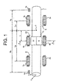
- Fig. 1 is a view showing a magnetic bearing apparatus in accordance with an embodiment of the present invention.
- Fig. 2 is a cross-sectional view of a
motor portion 10 taken along the line A-A of Fig. 1. - Fig. 3 is a view showing a magnetic force of a stator coil
acting on a rotor in the case where the rotor is not provided with
any
permanent magnet 11. - Fig. 4 is a view showing a magnetic force of a stator coil
acting on a rotor in the case where the rotor is provided with a
permanent magnet 11. - Fig. 5 is a vector diagram showing a magnetic force, of each
stator coil, acting on a
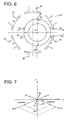
permanent magnet 11. - Fig. 6 is a view showing a magnetic force, of the stator coil,
acting on the
permanent magnet 11 in the case where the rotor is swung by ΔX in the x' direction. - Fig. 7 is a vector view showing a magnetic force, of the stator
coil, acting on the
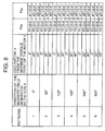
permanent magnet 11 in the case where the rotor is swung by ΔX in the x' direction. - Fig. 8 is a table showing a relationship of Fsx and Fsy together with a pattern etc. of magnetic field of the stator coil.
- Fig. 9 is a view showing the attractive force of the coil of the magnetic bearing and the rotor.
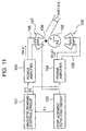
- Fig. 10 is a block diagram showing a control system of the magnetic bearing apparatus according to the present invention.
- Fig. 11 is a view showing a conventional magnetic bearing apparatus.
-
- An embodiment of the present invention will now be described with reference to Figs. 1 to 10 in more detail.
- Fig. 1 is a view showing a magnetic bearing apparatus in accordance with the embodiment.
- It is assumed that, as shown in the drawings, the x-axis is directed from the center of the cross-section of the
rotor 1 upwardly in the paper surface and the y-axis is directed from the paper surface in a direction backwardly. - Magnetic bearing portions 8 and 9 and a
motor portion 10 are formed at both ends and a central portion of therotor 1, respectively.Coils coils rotor 1 with each other and therotor 1 is held in a non-contact manner in a predetermined position in the x-direction by the balance of the attractive force. Although not shown, a pair ofcoils 3c and 3d are arranged also in the y-direction and therotor 1 is held in a predetermined position in the y-direction. - A
radial direction sensor 2a is further arranged in the x-direction in the end portion direction of therotor 1. Theradial direction sensor 2a detects the run-out of therotor 1 in the x-direction in a non-contact manner. Further, although not shown, a radial direction sensor 2b for detecting the run-out of therotor 1 in the y-direction is arranged in the y direction (in the paper backside direction) in the same manner. - The control unit of the magnetic bearing apparatus detects the run-out of the
rotor 1 by means of the radial direction sensors, performs the feedback control of the current of thecoils coils 3c and 3d is fed back and controlled so that the air gap in the y direction of the bearing portion 8 becomes a predetermined value. - In the same manner, the
coils coils 5c and 5d (not shown) in the y direction, theradial direction sensor 4a in the x direction and the radial direction sensor 4b in the y direction are arranged in the magnetic bearing portion 9. The structure and function of these components are the same as those of the bearing portion 8. - The
motor portion 10 is composed of apermanent magnet 11 composed of an N-pole and an S-pole fixed to therotor 1 and a stator where six coils are arranged around thispermanent magnet 11. In view of the drawing capacity, twocoils - The drive of the
motor portion 10 is performed by feeding three-phase alternating current to thesecoils permanent magnet 11 fixed to therotor 1 are attracted to the rotary magnetic field so that therotor 1 rotates in accordance with the rotation of the magnetic field. - Hereinafter, the sensors and the coils are simply referred to as, for example,
sensor 2 ,coil 6 in the case where the components are the same elements like thesensors 2a and 2b and thecoils - In the embodiment, in the thus constructed magnetic bearing apparatus, the unbalance of the magnetic force generated in the
motor portion 10 by the run-out of therotor 1 in the following steps is obviated. - (1) The run-out of the
rotor 1 in themotor portion 10 is inferred from the run-out of therotor 1 detected by theradial direction sensors - (2) The unbalance of the magnetic force whose generated
magnetic field affects the
permanent magnet 11 in thecoils 6 is inferred from the run-out of therotor 1 in themotor portion 10. - (3) The above-described unbalance of the magnetic force is
offset by means of the attracting force (magnetic force) of the
magnetic bearing portions 8 and 9 to the
rotor 1. -
- The above-described (1) to (3) will now be described below.
- (1) The run-out of the
rotor 1 in themotor portion 10 is inferred from the run-out of therotor 1 detected by theradial direction sensors - The run-out of the
rotor 1 is detected by theradial direction sensors rotor 1 in themotor portion 10 is calculated from the geometric positional relation of theradial direction sensors motor portion 10 and therotor 1. - If the method for thus estimating the run-out of the
rotor 1 in themotor portion 10 from the detection values of theradial direction sensors rotor 1 in themotor portion 10. - As shown in Fig. 1, L is the distance from the
gravitational center 7 of therotor 1 to the center of thecoil 6, Lb is the distance to the center of thecoil 5 of the magnetic bearing, Tb is the distance to theradial direction sensor 4, La is the distance to the center of thecoil 3 and Ta is the distance to theradial direction sensor 2. Note that, these distances are the distances in the axial direction of therotor 1. - Now, if Xa×sin 1 is the run-out in the x direction of the
rotor 1 detected by theradial direction sensor 4a and Xb×sin 2 is the run-out in the x direction of therotor 1 detected by theradial direction sensor 2a, the run-out ΔX in the x direction of therotor 1 of themotor 10 may be expressed by the following formula. Here, 1 and 2 represent the phases at any time t, respectively. The phase is generally expressed by = ω×t where ω is the angular velocity of therotor 1 and t is the time. Also, the run-out ΔY of the y direction is also calculated by the radial direction sensors 2b and 4b. - (2) The unbalance of the magnetic force of magnetic field generated by the
coils 6 to thepermanent magnet 11 is inferred by the run-out of therotor 1 in themotor portion 10. - Then, the method for obtaining the unbalance of the magnetic force generated between the
magnetic pole 11 and the magnetic field generated by thecoils 6 from the run-out of therotor 1 in themotor portion 10 will now be described. - The mechanism of the brush-less DC motor will first be described.
- Fig. 2 is a cross-sectional view taken along the line A-A of Fig. 1. The number of the
coils 6 is six as shown in the drawing. The U, V and W phase currents are caused to flow through thecoils coils coil 6f becomes the N-pole and thecoil 6e becomes the S-pole, whereas when the current is reversed, thecoil 6f becomes the S-pole and thecoil 6e becomes the N-pole. The same relationship is established for thecoils coils - Under the condition shown in Fig. 2, the U and V-shape coils are magnetically excited, and the composite magnetic field (the magnetic field, the direction indicated by an
arrow 21 of thick solid lines) is in the x' direction. Note that, the x' axis is in the direction from the N-pole to the S-pole of the composite magnetic field and the direction perpendicular to this is in the y' axis (in the coil direction of the non-electric supply phase). - The currents to be fed to the
coils 6 are switched over in order to switch the polarities of thecoils 6 one after another so that the composite magnetic field is rotated in a direction where therotor 1 is to be rotated as desired (for example, in the direction indicated by anarrow 20 indicated by a thin line). Thepermanent magnet 11 fixed to therotor 1 is attracted to this rotary magnetic field to rotate therotor 1. The switch-over of the currents is controlled by a motor driver while detecting the position of themagnetic poles 11. - As shown in Fig. 2, the maximum torque is applied to the
rotor 1 when the composite magnetic field of thecoils 6 is at 90 degrees to the direction of the magnetic field of thepermanent magnet 11. - Note that, when the phases of the currents to be fed to the
coils 6 are switched over to thereby rotate the magnetic field, the following explanation will be given assuming the above-described x' axis and y' axis are also rotated. - Next, in the case where the run-out generates in the rotor, in the
motor portion 10, it will be discussed how unbalance of the magnetic force influences in therotor 1. - First of all, the condition that the run-out is not generated in the
motor portion 10, i.e., the case of X0=Y0=δ 0 will be discussed. Here, X0 and Y0 are the air gaps between thecoils 6 and therotor 1 in the x' direction and the y' direction when therotor 1 is at the center of the motor, respectively. δ0 is a predetermined constant. - If the
permanent magnet 11 is not loaded on therotor 1, as shown in Fig. 3, the magnetic forces applied to therotor 1 are F1, F2, F3 and F4, and the F1 and F4 and the F2 and F4 are opposite in size and direction. Accordingly, the composite force obtained by adding F1 to F4 becomes zero. Accordingly, there is no unbalance in magnetic force. - Then, the magnetic force acting on the
rotor 1 from thecoils 6 when therotor 1 carrying thepermanent magnet 11 is in the center of the motor will be discussed. - An example of the magnetic force acting on the
rotor 1 in this case is shown in Fig. 4. Thepermanent magnet 11 receives the magnetic forces F1 to F6 from thecoils 6. The vector view showing the relationship among these forces is shown in Fig. 5. As shown in this drawing, since F3 and F6, F2 and F5 and F1 and F4 are opposite to each other in direction but the same in size, respectively,- the sum of these forces becomes zero so that no force in the radial direction generates in therotor 1. However, as is apparent from Fig. 4, the magnetic forces F1 to F6 generate a torque for rotating therotor 1 in the direction indicated by anarrow 22. Namely, the force for moving in the radial direction therotor 1, which causes themotor portion 10 to vibrate, is not generated but only the torque for rotating therotor 1 is generated. However, in general, the run-out of therotor 1 is generated in themotor portion 10, with the result that the unbalance of the magnetic force is generated and the vibration is generated in accordance with the rotation of therotor 1. - The magnetic force of the magnetic field by the
coils 6 acting on therotor 1 in the case where therotor 1 is swung by ΔX in the x direction in themotor portion 10, as shown in Fig. 6, will be discussed. In this case, the following relationship is established. - Now, if δ0=1[mm] and ΔX=0.2[mm], the following formulae are given.
- It is assumed that the magnetic force acting between the
rotor 1 and thecoil 6 is in proportion to the second powered value of the air gap, the following relationship is substantially established. - The forces F1 to F6 are shown in the vector view of Fig. 7. It will be understood that the
composite vector 23 of the magnetic forces (Fsx) is in the -y' direction. Note that, F2 and F5 are the same in size and opposite in direction and hence are offset. - From the above, it will be understood that, when the rotor is swung in the x direction, the magnetic force Fsx in the -y direction from the magnetic field generated by the
coils 6 is applied to therotor 1. Here, the angle α is the angle formed by the x' axis and the force F3. - Also, in the same manner, when the
rotor 1 is swung in the y' direction, the magnetic force Fsy in the -x' direction from the magnetic field generated by thecoils 6 is applied to therotor 1. - In the case where the
rotor 1 is swung by ΔX in the x' direction and swung by ΔY in the y' direction, the magnetic force Fs applied to therotor 1 is the composite force of Fsx and Fsy and is given by the following formula. Here, any one of Fs, Fsx and Fsy is a vector amount. - The method for seeking Fsx will now be described.
- Fsx is a function of three valuables of ΔX, the direction of the magnetic field generated by the
coils 6 and the rotary angle γ from the maximum torque point of the rotor 1 (assuming that the size of the magnetic field generated by thecoils 6 is kept constant). This is the case with respect to Fsy. - In order to obtain Fs from Fsx and Fsy in accordance with Formula (12), Fsx and Fsy are obtained in advance for various values of these three variables and formed into the database. This is then utilized.
- Incidentally, the directions of the magnetic field generated by the
coils 6 are six kinds of 0°, 60°, 120° 180°, 240° and 300° in view of the xy coordinate system fixed to thecoils 6. However, γ is the continuous amount from 0 to 60 (when γ reaches 60°, the magnetic field of thecoil 6 is switched over to the next phase and becomes 0°), and ΔX is also the continuous amount. Accordingly, if Fsx is obtained over all these three variables, the number of the data is tremendous or huge and it is difficult to perform the data process or the like. - Therefore, as shown in Fig. 8, the rotational angle from the maximum torque point of the
rotor 1 is considered for three cases of if γ is 0°, 20° or 40° by every 20°. When Fsx is actually obtained, if γ is 0°±10°, γ is 0°, and if γ is 20°±10°, γ is 20° and if γ is 40°±10°, γ is 40°. Here, γ is assumed to sort into any one of 0°, 20° or 40°. Note that, the above-described rotational angle is not limited to 0°, 20° or 40°. - If the value of γ is thus limited, Fsx is a one variable function of ΔX using the direction of the magnetic field generated by the
coil 6 and γ as the two parameters. - In the same manner, Fsy is a one variable function of ΔY.
- Fig. 8 shows a table showing the relationship among the direction of the magnetic field generated by the
coil 6, γ and Fsx and Fsy. - This table is divided into six patterns in accordance with the direction of the magnetic field generated by the
coil 6. The respective patterns are further divided into three in accordance with three γ 's, i.e., 0°, 20°, 40°. Then, for example, inpattern 1, γ is fixed to 0°, Fsx when therotor 1 is shifted by ΔX in the x' direction is fl(ΔX), fl(ΔX) is obtained with respect to various ΔX by the magnetic field analyses or experiments or the like in advance and formed into the database. In the same manner, f2(ΔX) and f3(ΔX) are obtained and formed into the database. Also, since themotor portion 10 has a contrasting structure to each pattern of the magnetic field generated by thecoil 6, the fl(ΔX), f2(ΔX) and f3(ΔX) obtained by thepattern 1 may be applied to the other patterns. In the same manner, with respect to Fsy, the gl(ΔY), g2(ΔY) and g3(ΔY) are formed into the database. - Also, the above-described fl(ΔX) and the like are not formed into the database but, for example, the approximation formation thereof may be obtained by using a minimum second power method and ΔX may be substituted for this to calculate the values.
- The direction of the magnetic field generated by the
coil 6 may be obtained by monitoring each current waveform of the U-phase, V-phase and W-phase of the motor. - Also, since γ is the relative angle of the
magnetic pole 11 to the magnetic field generated by thecoil 6, in order to obtain γ, it is necessary to know the position in the rotational direction of the magnetic pole of thepermanent magnet 11 and the direction of the magnetic field generated by thecoil 6. - The switchover point of the N-pole and the S-pole of the
permanent magnet 11 is detected. The position of the magnetic poles of thepermanent magnet 11, i.e., the phase of therotor 1 relative to the stator is then detected by means of the switchover point and the information of the rpm. Here, in order to detect the switchover point of the poles of thepermanent magnet 11, it is possible to use a hardware external sensor such as a Hall element or it is possible to use a so-called sensorless driver by which, for example, the motor is caused to run free and the switchover point is inferred from the induction electromotive force induced by the motor windings at this time. - (3) The above-described unbalance of the magnetic force is offset by means of the attractive force (magnetic force) of the magnetic bearing portions 8 and 9 acting on the
rotor 1. - Then, a description will be made of the method for offsetting the unbalance of the magnetic force between the
coil 6 and therotor 1 generated due to the run-out of therotor 1 in the above-describedmotor portion 10 by means of the magnetic force of the magnetic bearing portions 8 and 9. - Since Fs of Formula (12) is described in terms of the x'-y' coordinate system rotating together with the magnetic field, this is converted into the x-y coordinate system fixed to the coil 6 (or stator). Since Fs is the vector amount, the x component of this is Fx and the y component is Fy. In addition, with reference to Fig.9, it is assumed that the respective magnetic forces applied to the
rotor 1 in the x and y directions in the bearing portion 8 are Fax and Fay and the respective magnetic forces applied to therotor 1 in the x and y directions in the bearing portion 9 are Fbx and Fby. For the sake of easy understanding, the explanation of the coils of the magnetic bearing will be made only with thecoils coils coils coils - Formulae (13) and (14) are established from the balance of the forces applied to the
rotor 1. Also, Formulae (15) and (16) are established from the balance of the moments about thegravity center 7 of therotor 1. - The simultaneous equations of Formulae (13) to (16) are solved whereby it is possible to obtain the magnetic forces Fax, Fbx, Fay and Fby that are necessary for the magnetic bearings 8 and 9 in order to offset the unbalance of the magnetic forces generated in the
motor portion 10. - Then, current values for generating the magnetic forces Fax and Fay in the
coil 3 and the magnetic forces Fbx and Fby in thecoil 5 become necessary. - The relationships of Formulae (17) to (20) are established between the currents fed to the magnetic bearings 8 and 9 and the magnetic forces generated. These relationships may be formed into the database by obtaining these through the magnetic field analyses, the experiments and the like. Also, for example, the appropriation formula is obtained by using the minimum second power method. This may then be used as a formula of a function f. Here, Iax, Iay, Ibx and Iby are the currents to be fed to the
coils - If the current values are expressed inversely in terms of the magnetic forces from the relationships of Formulae (17) to (20), the following relationships are established. Note that, function f-1 is the reverse function of the function f.
- In the case where the relationship between the current of the coil and the magnetic force generated by the coil are formed into the database through the magnetic field analyses, the experiments and the like, it is possible to read out the current value for generating the necessary magnetic force from the database.
- Fig. 10 is a block diagram showing a control unit 80 of the magnetic bearing apparatus in accordance with the embodiment.
- A rotor
phase estimating unit 61 receives a magnetic pole switchover signal of thepermanent magnet 11 and an rpm signal of therotor 1 and outputs the position of the magnetic poles of thepermanent magnet 11. - The rpm signal represents the rpm of the
rotor 1 and the permanent magnet pole position switchover signal represents the timing when the switchover position of the poles of N-pole and S-pole of thepermanent magnet 11 passes through the sensor installed within the motor. The position of the magnetic poles of thepermanent magnet 11 is inferred from both signals. This is outputted to anFsx calculation section 66 and anFsy calculation section 69. Here, if the permanent magnet magnetic pole position switchover signal is counted, the rpm signal may be obtained and the rpm sensor per se may be dispensed with. - The
radial direction sensors radial direction sensors estimating unit 63. The xy components of the run-out of therotor 1 in the bearing portions 8 and 9 are detected by means of the respective sensors. These values are inputted into the motor portion rotor run-outestimating unit 63. Themotor portion 10 rotor run-outestimating unit 63 calculates and outputs the run-outs ΔX and ΔY of therotor 1 in themotor portion 10 on the basis of Formulae (4) and (5). Then, X0 and Y0 are added to ΔX and ΔY, and X0+ΔX and Y0+ΔY are inputted into anFsx calculation section 66 and anFsy calculation section 69, respectively. - An
Fsx estimating unit 64 is composed of apattern estimating section 65 and theFsx calculation section 66. Thepattern estimating section 65 monitors the currents of the U-phase, v-phase and W-phase motor windings and infers the magnetic field generated by thecoil 6 as shown in Fig. 8, i.e., the pattern of the magnetic field. - The
Fsx calculation section 66 obtains the pattern of magnetic field from thepattern estimating section 65 and the position of the magnetic poles of therotor 1 from the rotorphase estimating unit 61 to thereby infer the γ. Fsx calculation section further obtains the value obtained by adding the run-out ΔX of therotor 1 in themotor portion 10 to X0 from the motor portion rotor run-outestimating unit 63. Fsx is inferred in accordance with the table shown in Fig. 8 from these three values, i.e., the magnetic pattern, γ, and ΔX. Fsx is the magnetic force in the -y' direction generated by the run-out ΔX in the x' direction of therotor 1. - An
Fsx estimating section 67 is composed of apattern estimating section 68 and theFsy calculation section 69 and infers the magnetic force generated in the -x' direction when therotor 1 is swung in they' direction, i.e., Fsy in the same manner as in theFsx estimating unit 64. - An
Fs estimating unit 70 receives Fsx and Fsy from theFsx calculation section 66 andFsy calculation section 69 and composes Fs from Formula (12). Fs is the unbalance of the magnetic force that therotor 1 received from the magnetic field in themotor portion 10 and this amount is the vector amount. - An
x-y component separator 71 receives the vector amount Fs from theFs estimating unit 70 and decomposes this into Fx and Fy in the x-y coordinate system fixed to thecoil 6 or the bearing portions 8 and 9. Fx and Fy are an x component and a y component of the unbalance of the magnetic force applied to therotor 1 from the magnetic field generated by thecoil 6 by the run-out in themotor portion 10 of therotor 1. A magnetic bearing necessaryload estimating unit 72 calculates magnetic forces Fax, Fay, Fbx and Fby generated in the magnetic bearing portions 8 and 9 that are necessary for offsetting Fx and Fy from the balance of the moments about the gravity and the balance of the forces applied to therotor 1 represented by the Formulae (13) to (16). - A necessary
current estimating unit 73 receives the signals of the values of the magnetic forces Fax, Fay, Fbx and Fby from the magnetic bearing necessaryload estimating unit 72, infers the current Iax, Iay, Ibx and Iby that are necessary to generate these magnetic forces by thecoils 6 and feed the signal for generating these currents tocurrent amplifiers 75a to 75d. - Also, the
radial direction sensors coils PID compensators 74a to 74d andcurrent amplifiers 75a to 75d. This system of the control circuit 80 has been conventionally used to control the magnetic bearing apparatus. This portion operates as follows. - The
radial direction sensor 2a of the magnetic bearing portion 8 detects the run-out in the x direction of therotor 1 in the vicinity of the magnetic bearing 8 and outputs its signal to the PID (Proportional Integral Derivative)compensator 74a. This is a portion for performing the normal PID control to the magnetic bearing portions 8 and 9. - The PID control means the control of the coil currents for causing the change of the magnetic attractive force between the
rotor 1 and thecoil 3 to be in proportion to the velocity and the run-out of the rotor. The magnetic bearing apparatus obtains the bearing force through the PID control. Namely, if therotor 1 is swung in one direction of the radial direction, the magnetic force of thecoil 3 is fed back and controlled so that this run-out is returned back. - The output signal of the
PID compensator 74a is amplified in thecurrent amplifier 75a and a predetermined current is fed to thecoil 3a. Then, therotor 1 obtains the predetermined attractive force in the x direction of the bearing portion 8 and is supported at a predetermined air gap to thecoil 3. - The control of the attractive forces in the x and y directions in the magnetic bearing portion 9 and the control of the magnetic bearing portion 8 in the y direction are performed in the same manner.
- A current value from the necessary
current estimating unit 73 is added to the current value to be fed from thePID compensator 74a to thecurrent amplifier 75a. Then, the magnetic field generated by thecoil 3a is obtained by superimposing the bearing force for holding therotor 1 in a predetermined position and the magnetic force Fax for offsetting the unbalance of the magnetic force by the magnetic field generated due themotor portion 10. - The control of the magnetic bearing portion 8 in they direction and the control of the attractive force in the x and y direction in the magnetic bearing 9 are performed in the same way.
- By thus constituting the magnetic bearing apparatus 80, it is possible to offset the unbalance of the magnetic forces generated in the
motor portion 10 due to the run-out of therotor 1 and to thereby suppress the vibration generated in the stator. - In this embodiment, the run-out of the rotor in the
motor portion 10 is inferred from the run-out of therotor 1 with theradial direction sensors rotor 1 is inferred. However, for example, it is possible to install a magnetic flux detector sensor in the interior of themotor portion 10, to directly detect the magnetic flux in the air gap within the motor with this sensor and infer the unbalance of the magnetic forces applied between therotor 1 and thecoil 6 from this value. - In this embodiment, the magnetic force that the
rotor 1 receives is determined by the experiments or the like from ΔX, γ and the pattern of the magnetic field, and the like. However, in the case where the magnetic flux detector sensor is used, the relationship among the pattern of the magnetic field, γ, the output of the magnetic flux detector sensor and the magnetic force that therotor 1 receives is obtained through the experiments, the magnetic field analyses and the like and formed into the database. Then, this database is searched from the output of the magnetic flux sensor, γ and the magnetic pattern upon the operation of the magnetic bearing apparatus to thereby infer Fsx and Fsy. - Also, if an acceleration meter or a vibration meter or the like is mounted on a casing of the magnetic bearing apparatus or the
motor portion 10, whereby the vibration of themotor portion 10 is detected, and the control unit for adjusting the current of the coil of each magnetic bearing portion is added so as to reduce the vibration, it is possible to further suppress the vibration of the magnetic bearing apparatus. - According to the present invention, it is possible to reduce the vibration due to the unbalance of the magnetic force of the motor caused by the run-out of the rotor and to perform the miniaturization of the magnetic bearing portion and the high efficiency.
- Also, the hardware structure of the magnetic bearing apparatus may be used without any change to the conventional one. It is unnecessary to newly add the radial direction sensors. What is necessary is to add only the structure of the converters for converting the magnetic force generated in the coil into the current value flowing through the coil, an estimating unit for estimating the unbalance of the magnetic force within the motor by using a memory or the like or a microcomputer (Microprocessor) or DSP (Digital Signal Processor) within the magnetic bearing control unit.
- Also, in order to directly infer or measure the run-out of the rotor in the
motor portion 10, it is possible to obtain-the run-out of the rotor in the motor with high precision. - If the function to make it possible to miniaturize the actual vibration (acceleration) is added on the basis of the vibration generated to the outside of the magnetic bearing apparatus, it is possible to further enhance the vibration suppression effect.
Claims (7)
- A magnetic bearing apparatus comprising:a rotor;a motor portion provided in the rotor for rotating the rotor by a magnetic force;magnetically supporting coils for magnetically supporting the rotor in a radial direction in a predetermined position;a magnetic force unbalance obtaining means for obtaining an unbalance of the magnetic force generated in the motor portion by the rotor run-out in the radial direction from the predetermined position and to be applied to the rotor; anda magnetically support adjustment means for adjusting the magnetic force of the magnetically supporting coils so as to resist the unbalance of the magnetic force.
- The magnetic bearing apparatus according to claim 1, wherein the predetermined position of the rotor may be the position obtained in the case where the rotor is rotated with the rotary axis of the rotor passing through the gravitational center of the rotor, or the position obtained in the case where the magnetic force of the coils are corrected so that the magnetic force to be applied between the coils and the rotor is kept constant for one cycle through which the rotor is rotated for the variation of the air gap of the magnetic coils and the rotor and generated when the rotor is rotated with the rotary axis of the rotor passing through the gravitational center of the rotor
- The magnetic bearing apparatus according to claim 1, wherein the motor portion is a brush-less DC motor composed of a plurality of magnetic poles fixed to a rotor and a plurality of coils arranged around the magnetic poles.
- The magnetic bearing apparatus according to claim 3, wherein:the apparatus includes:a radial direction sensor for detecting the run-out in a radial direction of the rotor; anda first estimating means for estimating the run-out in the radial direction of the motor portion from the geometric positional relation among the radial direction sensor and the motor portion, and from the run-out in the radial direction of the rotor which is obtained by the radial direction sensor, and that:the magnetic force unbalance obtaining means comprising; a second estimating means for estimating the unbalance of the magnetic force acting on the rotor in the motor portion from the rotational angle of the magnetic poles, a magnetic field generated by the coil of the motor portion, and from the run-out of the motor portion in the radial direction inferred by the first estimating means.
- The magnetic bearing apparatus according to claim 4, wherein the second estimating means is a database recording thereon:the rotational angle of the magnetic poles;the magnetic field generated by the coils of the motor portion; andthe unbalance of the magnetic force acting on the rotor in the motor portion with respect to the run-out of the rotor in the radial direction.
- The magnetic bearing apparatus according to claim 2, wherein the magnetic force unbalance obtaining means comprising:a magnetic flux detecting sensor for detecting the magnetic flux existing in an air gap between the magnetic pole and the coils of the motor portion;a third estimating means for estimating, from the magnetic flux detected by the magnetic flux detecting sensor, the unbalance of the magnetic force of the motor portion.
- The magnetic bearing apparatus according to any one of claims 1 to 5, comprising:a detecting means for detecting vibration generated by the rotation of the rotor;a mechanism for controlling the magnetic force of the magnetic force supporting coils so that the vibration detected by the detecting means is reduced.
Applications Claiming Priority (2)
| Application Number | Priority Date | Filing Date | Title |
|---|---|---|---|
| JP2000315662A JP2002122138A (en) | 2000-10-16 | 2000-10-16 | Magnetic bearing device |
| JP2000315662 | 2000-10-16 |
Publications (2)
| Publication Number | Publication Date |
|---|---|
| EP1197670A2 true EP1197670A2 (en) | 2002-04-17 |
| EP1197670A3 EP1197670A3 (en) | 2003-12-17 |
Family
ID=18794729
Family Applications (1)
| Application Number | Title | Priority Date | Filing Date |
|---|---|---|---|
| EP01308737A Withdrawn EP1197670A3 (en) | 2000-10-16 | 2001-10-15 | Magnetic bearing apparatus |
Country Status (4)
| Country | Link |
|---|---|
| US (1) | US6770992B2 (en) |
| EP (1) | EP1197670A3 (en) |
| JP (1) | JP2002122138A (en) |
| KR (1) | KR20020030033A (en) |
Cited By (1)
| Publication number | Priority date | Publication date | Assignee | Title |
|---|---|---|---|---|
| CN110469583A (en) * | 2019-08-23 | 2019-11-19 | 广东美的暖通设备有限公司 | Magnetic axis bearing assembly and control method, compressor, air conditioner and storage medium |
Families Citing this family (29)
| Publication number | Priority date | Publication date | Assignee | Title |
|---|---|---|---|---|
| JP4314816B2 (en) * | 2002-11-28 | 2009-08-19 | ダイキン工業株式会社 | Brushless DC motor and brushless DC motor control device |
| US7107163B1 (en) * | 2003-05-06 | 2006-09-12 | Lockheed Martin Corporation | Magnetic levitation force control |
| US7157802B2 (en) * | 2003-10-16 | 2007-01-02 | Bodkin Design And Engineering Llc | Electrical power source |
| ITMI20040308A1 (en) * | 2004-02-24 | 2004-05-24 | Danieli Off Mecc | FORMASPIRE HEAD WITH VIBRATION DAMPING DEVICE |
| RU2399803C2 (en) * | 2004-06-15 | 2010-09-20 | Али ЭЛЬ-ШАФЕИ | Procedures for control of instability in hydro-dynamic bearings |
| EP2107668A1 (en) * | 2007-01-22 | 2009-10-07 | Tokyo University Of Science Educational Foundation Administrative Organization | Rotating electric machine |
| MY163687A (en) | 2008-04-17 | 2017-10-13 | Synchrony Inc | High-speed permanent magnet motor and generator with low-loss metal rotor |
| JP2011520410A (en) | 2008-04-18 | 2011-07-14 | シンクロニー,インコーポレイテッド | Magnetic thrust bearings using integrated electronics. |
| US8317651B2 (en) * | 2008-05-07 | 2012-11-27 | Fallbrook Intellectual Property Company Llc | Assemblies and methods for clamping force generation |
| US9583991B2 (en) | 2009-06-24 | 2017-02-28 | Synchrony, Inc. | Systems, devices, and/or methods for managing magnetic bearings |
| US8405267B2 (en) * | 2010-04-07 | 2013-03-26 | Chun Shig SOHN | Permanent magnetic device |
| WO2011163456A1 (en) | 2010-06-23 | 2011-12-29 | Synchrony, Inc. | Split magnetic thrust bearing |
| JP5827492B2 (en) * | 2011-04-28 | 2015-12-02 | 株式会社日立製作所 | Vibration characteristic measuring apparatus and vibration characteristic measuring method |
| US9310179B2 (en) * | 2012-02-01 | 2016-04-12 | Seagate Technology Llc | Spindle force actuator |
| US9638508B2 (en) | 2012-02-01 | 2017-05-02 | Seagate Technology Llc | Offset reduction for displacement sensor |
| US9482510B2 (en) | 2012-02-01 | 2016-11-01 | Seagate Technology, Llc | Noise measurement for measured displacement |
| JP5997597B2 (en) * | 2012-12-10 | 2016-09-28 | 株式会社荏原製作所 | Magnetic bearing device and method for reducing vibration caused by magnetic bearing device |
| SG2014000368A (en) * | 2013-01-03 | 2014-08-28 | Seagate Technology Llc | Spindle force actuator |
| RU2539690C1 (en) * | 2014-01-27 | 2015-01-27 | Федеральное государственное бюджетное образовательное учреждение высшего профессионального образования "Уфимский государственный авиационный технический университет" | Sensorless control over rotor position in contactless bearings |
| US9816965B2 (en) | 2014-11-14 | 2017-11-14 | General Electric Company | Method to detect vibration nodes between a sensor and an actuator in a rotatable component |
| JP6435811B2 (en) * | 2014-11-28 | 2018-12-12 | 村田機械株式会社 | Magnetic position detector |
| JP6590070B2 (en) * | 2016-08-12 | 2019-10-16 | 株式会社Soken | Electric motor system |
| RU2656871C1 (en) * | 2017-04-28 | 2018-06-07 | федеральное государственное бюджетное образовательное учреждение высшего образования "Уфимский государственный авиационный технический университет" | Method of controlling the rotor position of electric machine on non-contact bearings (variants) and electric machine for its implementation |
| JP6447662B2 (en) * | 2017-05-09 | 2019-01-09 | ダイキン工業株式会社 | Electric motor system and turbo compressor provided with the same |
| DE102017212805A1 (en) * | 2017-07-26 | 2019-01-31 | Robert Bosch Gmbh | Method for reducing a magnetic imbalance of an electric machine and rotary electric machines |
| DE102019112735A1 (en) * | 2019-05-15 | 2020-11-19 | Maschinenfabrik Rieter Ag | Method for identifying a spinning rotor on a rotor spinning machine and rotor spinning machine |
| US11923728B2 (en) | 2020-12-17 | 2024-03-05 | Waymo Llc | Method of determining runout |
| CN113565874A (en) * | 2021-07-26 | 2021-10-29 | 中山大学 | Magnetic suspension sensor interference suppression method based on variable step length minimum mean square error |
| CN116858172B (en) * | 2023-09-05 | 2023-11-14 | 苏州中科科仪技术发展有限公司 | Radial stator performance detection tool and detection method of magnetic suspension molecular pump |
Citations (4)
| Publication number | Priority date | Publication date | Assignee | Title |
|---|---|---|---|---|
| JPH07259854A (en) * | 1994-03-24 | 1995-10-09 | Seiko Seiki Co Ltd | Magnetic bearing device |
| EP0739078A2 (en) * | 1995-04-21 | 1996-10-23 | Tadashi Fukao | Electromagnetic rotating machine |
| US6111333A (en) * | 1998-03-13 | 2000-08-29 | Hitachi, Ltd. | Magnetic bearing, rotating machine mounting the same, and method for driving rotating machine |
| EP1085225A2 (en) * | 1999-09-13 | 2001-03-21 | Ebara Corporation | Magnetic bearing device for motor-combined structure |
Family Cites Families (7)
| Publication number | Priority date | Publication date | Assignee | Title |
|---|---|---|---|---|
| US4629262A (en) * | 1985-06-24 | 1986-12-16 | Sperry Corporation | Position sensor for magnetic suspension and pointing system |
| JP2835522B2 (en) * | 1989-01-18 | 1998-12-14 | 明 千葉 | Electromagnetic rotary machine with radial rotating body position control winding and radial rotating body position control device |
| JPH0720359B2 (en) * | 1990-03-16 | 1995-03-06 | 株式会社荏原製作所 | Unbalance correction device for rotating body |
| US5084643A (en) * | 1991-01-16 | 1992-01-28 | Mechanical Technology Incorporated | Virtual rotor balancing in magnetic bearings |
| JP3135410B2 (en) * | 1993-04-14 | 2001-02-13 | 光洋精工株式会社 | Magnetic bearing device |
| US5880549A (en) * | 1995-03-30 | 1999-03-09 | Akira Chiba | Switched reluctance rotator |
| US5703424A (en) * | 1996-09-16 | 1997-12-30 | Mechanical Technology Inc. | Bias current control circuit |
-
2000
- 2000-10-16 JP JP2000315662A patent/JP2002122138A/en active Pending
-
2001
- 2001-10-15 US US09/978,257 patent/US6770992B2/en not_active Expired - Fee Related
- 2001-10-15 EP EP01308737A patent/EP1197670A3/en not_active Withdrawn
- 2001-10-16 KR KR1020010063717A patent/KR20020030033A/en not_active Application Discontinuation
Patent Citations (4)
| Publication number | Priority date | Publication date | Assignee | Title |
|---|---|---|---|---|
| JPH07259854A (en) * | 1994-03-24 | 1995-10-09 | Seiko Seiki Co Ltd | Magnetic bearing device |
| EP0739078A2 (en) * | 1995-04-21 | 1996-10-23 | Tadashi Fukao | Electromagnetic rotating machine |
| US6111333A (en) * | 1998-03-13 | 2000-08-29 | Hitachi, Ltd. | Magnetic bearing, rotating machine mounting the same, and method for driving rotating machine |
| EP1085225A2 (en) * | 1999-09-13 | 2001-03-21 | Ebara Corporation | Magnetic bearing device for motor-combined structure |
Non-Patent Citations (1)
| Title |
|---|
| PATENT ABSTRACTS OF JAPAN vol. 1996, no. 02, 29 February 1996 (1996-02-29) & JP 07 259854 A (SEIKO SEIKI CO LTD), 9 October 1995 (1995-10-09) * |
Cited By (1)
| Publication number | Priority date | Publication date | Assignee | Title |
|---|---|---|---|---|
| CN110469583A (en) * | 2019-08-23 | 2019-11-19 | 广东美的暖通设备有限公司 | Magnetic axis bearing assembly and control method, compressor, air conditioner and storage medium |
Also Published As
| Publication number | Publication date |
|---|---|
| EP1197670A3 (en) | 2003-12-17 |
| JP2002122138A (en) | 2002-04-26 |
| KR20020030033A (en) | 2002-04-22 |
| US6770992B2 (en) | 2004-08-03 |
| US20020074883A1 (en) | 2002-06-20 |
Similar Documents
| Publication | Publication Date | Title |
|---|---|---|
| EP1197670A2 (en) | Magnetic bearing apparatus | |
| EP0739078B1 (en) | Electromagnetic rotating machine | |
| EP0920109B1 (en) | Bearingless rotary machine | |
| EP1188943B1 (en) | Magnetic levitation rotating machine | |
| US6707200B2 (en) | Integrated magnetic bearing | |
| US6268674B1 (en) | Magnetic bearing apparatus | |
| EP0939480A2 (en) | Permanent magnet synchronous machine with integrated magnetic bearings | |
| EP1115193A2 (en) | Magnetic levitation motor and method for manufacturing the same | |
| US7078839B2 (en) | Self-bearing step motor and its control method | |
| JP3678517B2 (en) | Radial force generator, coiled rotating machine, and rotating device | |
| JPWO2015019463A1 (en) | Electric motor system and magnetic bearing system | |
| Takenaga et al. | A principle and winding design of consequent-pole bearingless motors | |
| US8324852B2 (en) | Motor position detecting method, motor driving unit, and pump | |
| JP4889350B2 (en) | Magnetic bearing device | |
| JP2017150599A (en) | Electric motor and motor control system | |
| JPH08322194A (en) | Axial magnetic levitation motor and rotating machine employing it | |
| JPH0743265B2 (en) | Rotation angle sensor | |
| JP3351310B2 (en) | Rotary shaft position measuring system, magnetic bearing and synchronous motor provided with the same | |
| JP3524303B2 (en) | Radial rotating body position control device | |
| JP2000161358A (en) | Magnetic bearing device | |
| JP4034358B2 (en) | DC motor actuator generating radial force | |
| JP3701122B2 (en) | Bearingless rotating machine | |
| JP3701118B2 (en) | Bearingless rotating machine | |
| JP3550736B2 (en) | Magnetic bearing device | |
| JPH07264798A (en) | Motor with bearing function and controlling method therefor |
Legal Events
| Date | Code | Title | Description |
|---|---|---|---|
| PUAI | Public reference made under article 153(3) epc to a published international application that has entered the european phase |
Free format text: ORIGINAL CODE: 0009012 |
|
| AK | Designated contracting states |
Kind code of ref document: A2 Designated state(s): AT BE CH CY DE DK ES FI FR GB GR IE IT LI LU MC NL PT SE TR |
|
| AX | Request for extension of the european patent |
Free format text: AL;LT;LV;MK;RO;SI |
|
| PUAL | Search report despatched |
Free format text: ORIGINAL CODE: 0009013 |
|
| AK | Designated contracting states |
Kind code of ref document: A3 Designated state(s): AT BE CH CY DE DK ES FI FR GB GR IE IT LI LU MC NL PT SE TR |
|
| AX | Request for extension of the european patent |
Extension state: AL LT LV MK RO SI |
|
| RIC1 | Information provided on ipc code assigned before grant |
Ipc: 7H 02K 7/09 B Ipc: 7F 16C 32/04 B Ipc: 7F 16C 39/06 A |
|
| 17P | Request for examination filed |
Effective date: 20040526 |
|
| RAP1 | Party data changed (applicant data changed or rights of an application transferred) |
Owner name: BOC EDWARDS JAPAN LIMITED |
|
| AKX | Designation fees paid |
Designated state(s): DE FR GB |
|
| 17Q | First examination report despatched |
Effective date: 20040730 |
|
| STAA | Information on the status of an ep patent application or granted ep patent |
Free format text: STATUS: THE APPLICATION IS DEEMED TO BE WITHDRAWN |
|
| 18D | Application deemed to be withdrawn |
Effective date: 20050628 |