EP1189422A2 - System and method for providing lifeline power service to digital subscriber line customers - Google Patents
System and method for providing lifeline power service to digital subscriber line customers Download PDFInfo
- Publication number
- EP1189422A2 EP1189422A2 EP01302269A EP01302269A EP1189422A2 EP 1189422 A2 EP1189422 A2 EP 1189422A2 EP 01302269 A EP01302269 A EP 01302269A EP 01302269 A EP01302269 A EP 01302269A EP 1189422 A2 EP1189422 A2 EP 1189422A2
- Authority
- EP
- European Patent Office
- Prior art keywords
- power
- integrated access
- access device
- tip
- service
- Prior art date
- Legal status (The legal status is an assumption and is not a legal conclusion. Google has not performed a legal analysis and makes no representation as to the accuracy of the status listed.)
- Granted
Links
Images


Classifications
-
- H—ELECTRICITY
- H04—ELECTRIC COMMUNICATION TECHNIQUE
- H04M—TELEPHONIC COMMUNICATION
- H04M19/00—Current supply arrangements for telephone systems
- H04M19/001—Current supply source at the exchanger providing current to substations
-
- Y—GENERAL TAGGING OF NEW TECHNOLOGICAL DEVELOPMENTS; GENERAL TAGGING OF CROSS-SECTIONAL TECHNOLOGIES SPANNING OVER SEVERAL SECTIONS OF THE IPC; TECHNICAL SUBJECTS COVERED BY FORMER USPC CROSS-REFERENCE ART COLLECTIONS [XRACs] AND DIGESTS
- Y02—TECHNOLOGIES OR APPLICATIONS FOR MITIGATION OR ADAPTATION AGAINST CLIMATE CHANGE
- Y02D—CLIMATE CHANGE MITIGATION TECHNOLOGIES IN INFORMATION AND COMMUNICATION TECHNOLOGIES [ICT], I.E. INFORMATION AND COMMUNICATION TECHNOLOGIES AIMING AT THE REDUCTION OF THEIR OWN ENERGY USE
- Y02D30/00—Reducing energy consumption in communication networks
- Y02D30/70—Reducing energy consumption in communication networks in wireless communication networks
Definitions
- This invention relates to the field of digital subscriber lines and, more particularly, to providing power to digital subscriber line customer premise equipment in order to maintain service during times of power outages.
- twisted-pair copper wire also referred to as tip-ring pairs
- modem data technologies are taxing the bandwidth limitations of twisted-pair service.
- Some operating companies are experimenting with fiber optic to the home, cable television (CATV) equipment, etc., in order to increase bandwidth for home and business use. These technologies are expensive to the operating companies because they require the operating company to physically rewire an entire community from each customer premise to a local switching office.
- CATV cable television
- DSL digital subscriber line
- ADSL asynchronous DSL
- SDSL synchronous DSL
- the advantage of DSL is that it may be implemented over the current tip-ring pair infrastructure and, with some DSL systems, the current customer premise telephone equipment may be used.
- voice communication from a customer premise is viewed as one more payload for the DSL. Therefore, voice over DSL (VoDSL) is proposed as a method of more fully utilizing the bandwidth of the twisted pair.
- An integrated access device is used on the customer premise to integrate voice service over the data service.
- each DSL service provider must face is how the customer premise integrated access device is to be powered.
- POTS telephony 48 volts DC is supplied from the central office for most functions, and approximately 90 volts AC is supplied from the central office for ringing.
- the integrated access device must supply these voltages to all POTS telephones to which it is connected; as well as supply power to the other components (interfaces, routers, etc., as will be discussed further, below, in connection with FIG. 2).
- Some DSL standards specify that power is delivered from the central office in a similar manner as POTS service.
- the integrated access device requires power at all times, and requires more power than a POTS telephone.
- central power delivery is a very expensive proposition for the operating company.
- most integrated access devices are powered from the consumer power company (wherein the customer pays for the power).
- This problem is solved and a technical advance is achieved in the art by a system and method that provides lifeline service to voice over DSL (VoDSL) customers on an individual, as needed basis.
- VoIP voice over DSL
- an integrated access device loses power, it sends a series of predefined messages.
- power is provided to the requesting integrated access device from the central office.
- a power supply at the central office provides power through an isolator circuit to a relay on the tip-ring pair. 48 to 200 volts are sent over the tip-ring pair (depending upon the application) to the integrated access device.
- the data connection may also be powered in this manner or, in order to save wattage, the data connection may be disconnected and only the telephones powered.
- the central office power supply may be sufficient to handle simultaneous demands, or may be sized to accommodate a predefined number of integrated access devices.
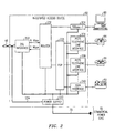
- FIG. 1 illustrates a block diagram in which a lifeline service for voice over DSL according to this invention may be implemented.
- FIG. 1 is a block diagram of a local service region 10 comprising a plurality of customer premises 20, 21, 22 and 23, which are served by a switching office 24. Customer premises 20-23 are also served by various portions of the commercial power grid 26.
- Switching office 24 includes a digital subscriber line access multiplexer (DSLAM) 26.
- DSLAM 26 includes, in this exemplary embodiment, DSL terminal units 28 and 30. Each DSL terminal unit 28 and 30 supports a plurality (16 in this exemplary embodiment) of interfaces 32 for terminating twisted-wire pair from customer premise 20-23.
- DSL terminal units 28 and 30 receive data from customer premises 20-23, multiplex the data into one stream and send it out on lines 40 and 42, respectively, for further processing.
- DSL terminal units 28 and 30 receive data on lines 40 and 42, demultiplex the data per destination and send it out on the appropriate interface 32.
- only two DSL terminal units are shown, however, there are usually more in an operating switching office depending on the particular implementation.
- each DSL terminal unit 28 interface 32 is connected by a tip-ring pair 48 to an integrated access device 50, 51, 52 and 53 at customer premise 20-23, respectively.
- Integrated access devices 50-53 send and receive a digital stream over tip-ring pair 48 and distribute the signals to their intended destinations, as will be discussed further below in connection with FIG. 2.
- tip-ring pairs 48 do not normally carry a power load.
- a customer premise may comprise data terminals 60 and 62, such as a personal computer, workstation or other data devices, and a plurality of POTS telephones 64, 65, 66, 67 and 68 and ISDN telephone 69.
- integrated access device 50-52 is connected via AC cord 70, 71, 72 and 73 to portions of the commercial power grid 26.
- switching office 24 includes a power supply 100.
- Power supply 100 may be the same power supply as supplying power to the entire switching office 24 or may be, preferably, an independent, auxiliary or backup power supply.
- a plurality of isolators 102 are connected to power supply and to lines 104, which are connected to tip-ring pairs 48.
- Power supply 100 may be 40 volts to 200 volts.
- Power supply 100 does not have to be engineered to be large enough to supply full power requirements of all of the integrated access devices connected to the switching office 24, as will be discussed further, below. Thus, the operating company may realize a savings in both physical plant and cost of electricity by reasons of this invention.
- Isolators 102 may be transformers, op amps or similar devices.
- a plurality of relays 106 are shown to connect isolators 102 to tip-ring pairs 48 under direction of a controller 108.
- Relays 106 are shown here as exemplary; however, they may be included within isolators 102 or may be, for example, solid state switches or op amps as is known in the art.
- the purpose of relays 106 is to isolate tip-ring pair 48 from power supply 100 when not in use and to provide power to integrated access devices 50-53 when power is required by any one or more of them.
- Isolators 102 isolate power supply 100 from data on tip-ring pairs 48 and to prevent cross talk and other "linkage" as is known in the art.
- a further variation may include a capacitor or other chargeable device that is charged by the power supply 100.
- the line is powered and the power supply 100 may be used to charge another device.
- one, two or a plurality of integrated access devices such as 50-53 may be powered when their commercial power supply 26 is unavailable.
- switching office 24 may provide power to the integrated access devices in the area, either on a full power basis so that both data and telephone service may be maintained or on a limited power basis wherein only telephone service (lifeline service) is maintained. The more integrated access devices that must be powered from central switching office 24, the more likely it is that only telephones will be powered.
- intelligence in controller 108 provides a means for tailoring power backup to integrated access devices 50-53 so that power supply 100 may be engineered to be as inexpensive as possible given the number of integrated access devices in an area supported by the switching office 24.
- Each integrated access device 50-53 informs, in this exemplary embodiment, its respective interface 32 when commercial power has been interrupted.
- Each integrated access device 50-53 sends three messages in succession to an interface 32 informing them of the loss of power (again, according to this exemplary embodiment). These messages are known in the art as "dying gasp" messages.
- a keep-alive message may be used to inform DSLAM 26 via interfaces 32 when to close relays 106.
- a keep-alive message may be sent from DSL terminal unit 28 to integrated access device 50 every X seconds, wherein DSL terminal unit 28 expects a message back from integrated access device 50 in response to its message.
- Integrated access device 50 is the same or similar to all the other integrated access devices 51-53.
- Integrated access device 50 is connected to tip-ring pair 48 via a digital subscriber line interface 200.
- Digital subscriber line interface 200 sends and receives signals between tip-ring pair 48 and router 202.
- Router 202 determines which data stream is intended for data terminal 60 and sends such data stream through, for example, an ETHERNET 10 base T interface 204 to terminal 60.
- Telephone traffic is routed from router 202 to digital signal processor (DSP) 206.
- DSP 206 demultiplexes the signal and sends the signals to its respective POTS line interface 208 or ISDN interface 210.
- POTS line interface 208 provides standard BORSCHT functions as are known in the art.
- ISDN interface 210 provides the 2B + D channels for ISDN telephone 69.
- Power is normally supplied to the components of integrated access device 50 via power supply 220.
- Power supply 220 normally transforms standard AC (110 volts, 60 Hz in the United States) from commercial power grid 26 (via cord 70) into DC power as required by each of the components of integrated access device 50.
- DSL interface 200 when commercial power supply fails, DSL interface 200 sends messages to its respective central office interface in a DSLAM DSL terminal unit via tip-ring pair 48. Power is then supplied through tip-ring pair 48 and sent via lines 224 to power supply 220. Power supply 220 then regulates and distributes the power. In another embodiment of this invention, power supply may disconnect power to the data stream by disabling power to the 10 base T interface 204, thus conserving power from power supply 100 (FIG. 1).
- FIG. 3 A flow chart of processing for determining whether power is necessary at the integrated access device is shown in FIG. 3. Processing starts in oval 300 and moves to box 302 where a counter is cleared. Processing moves to decision diamond 304 where a determination is made if a power error message has been received from the integrated access device. If a power error message has not been received then processing returns back to decision diamond 304.
- processing continues to box 306 where the counter is incremented. Processing continues to decision diamond 308 where a determination is made if the counter is over a threshold. If the counter is not over a threshold, then processing proceeds back to decision diamond 304. If the counter is over a threshold, then a power error has been detected at the integrated access device. Therefore, processing proceeds to action blocks 310 where the relay that provides power is closed.
- Processing continues to decision diamond 312 where a determination is made if the power error has been cleared. In other words, a power OK message has been received. If not, then processing returns to box 310 where the relay is maintained in the closed position. If the power OK message has been received, then processing continues to action blocks 314 where the relay is opened and processing loops back to action blocks 302.
- a loop could be added that a predetermined number of power OK messages must be received the relay is reopened to prevent thrashing turning the relay of opening and closing the relay.
Abstract
Description
- This invention relates to the field of digital subscriber lines and, more particularly, to providing power to digital subscriber line customer premise equipment in order to maintain service during times of power outages.
- Most telephone operating companies have an infrastructure of twisted-pair copper wire (also referred to as tip-ring pairs) connecting a telephone at a customer premise to a switching office. While this has been adequate for voice service for over a hundred years, modem data technologies are taxing the bandwidth limitations of twisted-pair service. Some operating companies are experimenting with fiber optic to the home, cable television (CATV) equipment, etc., in order to increase bandwidth for home and business use. These technologies are expensive to the operating companies because they require the operating company to physically rewire an entire community from each customer premise to a local switching office.
- One new data service technology that takes advantage of the currently extant twisted-pair infrastructure is digital subscriber line (DSL). DSL comes in many varieties, such as asynchronous DSL (ADSL) and synchronous DSL (SDSL), each having further "flavors". The advantage of DSL is that it may be implemented over the current tip-ring pair infrastructure and, with some DSL systems, the current customer premise telephone equipment may be used. Increasingly, voice communication from a customer premise is viewed as one more payload for the DSL. Therefore, voice over DSL (VoDSL) is proposed as a method of more fully utilizing the bandwidth of the twisted pair. An integrated access device is used on the customer premise to integrate voice service over the data service.
- One issue that each DSL service provider must face is how the customer premise integrated access device is to be powered. In POTS telephony, 48 volts DC is supplied from the central office for most functions, and approximately 90 volts AC is supplied from the central office for ringing. The integrated access device must supply these voltages to all POTS telephones to which it is connected; as well as supply power to the other components (interfaces, routers, etc., as will be discussed further, below, in connection with FIG. 2). Some DSL standards specify that power is delivered from the central office in a similar manner as POTS service. However, the integrated access device requires power at all times, and requires more power than a POTS telephone. Thus, central power delivery is a very expensive proposition for the operating company. Hence, most integrated access devices are powered from the consumer power company (wherein the customer pays for the power).
- One issue with VoDSL when power is provided by the power company is that, if the power goes out at the consumer premise, the customer can no longer use either the data terminal or, more importantly, the telephones. This is a problem in the art in that many regulatory agencies require emergency (911) service ("lifeline service") even during periods of power outages.
- An obvious solution is to use a battery backup at the integrated access device. This solution, however, causes as many problems as it solves. In normal operation, an integrated access device does not use the batteries and the user does not know (or care) whether the batteries are fully charged or not. Only when the power goes out does the user determine whether the batteries are charged. Such a situation is not acceptable to most regulatory agencies. Battery monitoring by the operating company is generally required. However, this monitoring usually includes sending crafts people to the customer premise to replace batteries, etc. which is the most expensive method of monitoring anything.
- Therefore, a problem in the art is that there is no reliable backup system or method for providing power for lifeline service to commercially powered voice over DSL customers.
- This problem is solved and a technical advance is achieved in the art by a system and method that provides lifeline service to voice over DSL (VoDSL) customers on an individual, as needed basis. When an integrated access device loses power, it sends a series of predefined messages. In response, power is provided to the requesting integrated access device from the central office. To this end, a power supply at the central office provides power through an isolator circuit to a relay on the tip-ring pair. 48 to 200 volts are sent over the tip-ring pair (depending upon the application) to the integrated access device. The data connection may also be powered in this manner or, in order to save wattage, the data connection may be disconnected and only the telephones powered.
- The central office power supply may be sufficient to handle simultaneous demands, or may be sized to accommodate a predefined number of integrated access devices.
- A more complete understanding of this invention may be obtained from the following description, taken in conjunction with the drawings, in which:
- FIG. 1 is a block diagram of a voice over DSL system in which lifeline service is provided according to an exemplary embodiment of this invention;
- FIG. 2 is a block diagram of an integrated access device wherein lifeline service is provided according to FIG. 1; and
- FIG. 3 is a flowchart of actions performed in order to determine when lifeline service is necessary and the steps to implement the lifeline service.
-
- FIG. 1 illustrates a block diagram in which a lifeline service for voice over DSL according to this invention may be implemented. FIG. 1 is a block diagram of a
local service region 10 comprising a plurality ofcustomer premises office 24. Customer premises 20-23 are also served by various portions of thecommercial power grid 26. - Switching
office 24 includes a digital subscriber line access multiplexer (DSLAM) 26. DSLAM 26 includes, in this exemplary embodiment,DSL terminal units DSL terminal unit interfaces 32 for terminating twisted-wire pair from customer premise 20-23. As is known in the art,DSL terminal units lines DSL terminal units lines appropriate interface 32. In this exemplary embodiment, only two DSL terminal units are shown, however, there are usually more in an operating switching office depending on the particular implementation. - In this exemplary embodiment, each
DSL terminal unit 28interface 32 is connected by a tip-ring pair 48 to an integratedaccess device ring pair 48 and distribute the signals to their intended destinations, as will be discussed further below in connection with FIG. 2. In this exemplary embodiment, tip-ring pairs 48 do not normally carry a power load. A customer premise may comprisedata terminals POTS telephones telephone 69. In order to provide power, integrated access device 50-52 is connected viaAC cord commercial power grid 26. - In the prior art, when a part of the
commercial power grid 26 is interrupted for any reason, i.e., cable break, electrical storm etc., one or more of integrated access devices 50-53 become inoperative. As a result, the affecteddata devices commercial power grid 26, a further means for providing power for lifeline telephone service, i.e., 911 or other emergency services, is required. - To this end, switching
office 24 includes apower supply 100.Power supply 100 may be the same power supply as supplying power to theentire switching office 24 or may be, preferably, an independent, auxiliary or backup power supply. A plurality ofisolators 102 are connected to power supply and tolines 104, which are connected to tip-ring pairs 48.Power supply 100 may be 40 volts to 200volts. Power supply 100 does not have to be engineered to be large enough to supply full power requirements of all of the integrated access devices connected to the switchingoffice 24, as will be discussed further, below. Thus, the operating company may realize a savings in both physical plant and cost of electricity by reasons of this invention.Isolators 102 may be transformers, op amps or similar devices. - A plurality of
relays 106 are shown to connectisolators 102 to tip-ring pairs 48 under direction of acontroller 108.Relays 106 are shown here as exemplary; however, they may be included withinisolators 102 or may be, for example, solid state switches or op amps as is known in the art. The purpose ofrelays 106 is to isolate tip-ring pair 48 frompower supply 100 when not in use and to provide power to integrated access devices 50-53 when power is required by any one or more of them.Isolators 102 isolatepower supply 100 from data on tip-ring pairs 48 and to prevent cross talk and other "linkage" as is known in the art. A further variation may include a capacitor or other chargeable device that is charged by thepower supply 100. Then the line is powered and thepower supply 100 may be used to charge another device. By means of this configuration, one, two or a plurality of integrated access devices such as 50-53 may be powered when theircommercial power supply 26 is unavailable. In this manner, a single interruption in the commercial power supply that affects one integrated access device such as 50 can be handled economically by the switching office providing power to just that one device. If an area-wide power outage occurs, switchingoffice 24 may provide power to the integrated access devices in the area, either on a full power basis so that both data and telephone service may be maintained or on a limited power basis wherein only telephone service (lifeline service) is maintained. The more integrated access devices that must be powered fromcentral switching office 24, the more likely it is that only telephones will be powered. Thus, according to this exemplary embodiment of this invention, intelligence incontroller 108 provides a means for tailoring power backup to integrated access devices 50-53 so thatpower supply 100 may be engineered to be as inexpensive as possible given the number of integrated access devices in an area supported by the switchingoffice 24. - Each integrated access device 50-53 informs, in this exemplary embodiment, its
respective interface 32 when commercial power has been interrupted. Each integrated access device 50-53 sends three messages in succession to aninterface 32 informing them of the loss of power (again, according to this exemplary embodiment). These messages are known in the art as "dying gasp" messages. - Alternatively, a keep-alive message may be used to inform
DSLAM 26 viainterfaces 32 when to close relays 106. For example, a keep-alive message may be sent fromDSL terminal unit 28 tointegrated access device 50 every X seconds, whereinDSL terminal unit 28 expects a message back fromintegrated access device 50 in response to its message. - Turning now to FIG. 2, an
integrated access device 50 is shown.Integrated access device 50 is the same or similar to all the other integrated access devices 51-53.Integrated access device 50 is connected to tip-ring pair 48 via a digitalsubscriber line interface 200. Digitalsubscriber line interface 200 sends and receives signals between tip-ring pair 48 androuter 202.Router 202 determines which data stream is intended fordata terminal 60 and sends such data stream through, for example, anETHERNET 10base T interface 204 toterminal 60. - Telephone traffic is routed from
router 202 to digital signal processor (DSP) 206.DSP 206 demultiplexes the signal and sends the signals to its respectivePOTS line interface 208 orISDN interface 210.POTS line interface 208 provides standard BORSCHT functions as are known in the art.ISDN interface 210 provides the 2B + D channels forISDN telephone 69. - Power is normally supplied to the components of
integrated access device 50 viapower supply 220.Power supply 220 normally transforms standard AC (110 volts, 60 Hz in the United States) from commercial power grid 26 (via cord 70) into DC power as required by each of the components ofintegrated access device 50. - According to an exemplary embodiment of this invention, when commercial power supply fails,
DSL interface 200 sends messages to its respective central office interface in a DSLAM DSL terminal unit via tip-ring pair 48. Power is then supplied through tip-ring pair 48 and sent vialines 224 topower supply 220.Power supply 220 then regulates and distributes the power. In another embodiment of this invention, power supply may disconnect power to the data stream by disabling power to the 10base T interface 204, thus conserving power from power supply 100 (FIG. 1). - A flow chart of processing for determining whether power is necessary at the integrated access device is shown in FIG. 3. Processing starts in
oval 300 and moves tobox 302 where a counter is cleared. Processing moves todecision diamond 304 where a determination is made if a power error message has been received from the integrated access device. If a power error message has not been received then processing returns back todecision diamond 304. - If a power error message has been received, then processing continues to box 306 where the counter is incremented. Processing continues to
decision diamond 308 where a determination is made if the counter is over a threshold. If the counter is not over a threshold, then processing proceeds back todecision diamond 304. If the counter is over a threshold, then a power error has been detected at the integrated access device. Therefore, processing proceeds to action blocks 310 where the relay that provides power is closed. - Processing continues to
decision diamond 312 where a determination is made if the power error has been cleared. In other words, a power OK message has been received. If not, then processing returns tobox 310 where the relay is maintained in the closed position. If the power OK message has been received, then processing continues to action blocks 314 where the relay is opened and processing loops back to action blocks 302. - Additionally, a loop could be added that a predetermined number of power OK messages must be received the relay is reopened to prevent thrashing turning the relay of opening and closing the relay.
- It is to be understood that the above-described embodiment is merely an illustrative principle of the invention, and that many variations may be devised by those skilled in the art without departing from the scope of this invention. It is, therefore, intended that such variations be included within the scope of the following claims.
Claims (13)
- A system for providing backup power for digital subscriber line service, said system comprising:a switching office having a power supply and a digital subscriber line terminal unit;an integrated access device at a customer premise configured to route voice service to one or more telephones and data service to a data device, said integrated access device connected to said digital terminal unit;a tip-ring pair connecting the switching office to the integrated access device; andmeans in the switching office for determining power status of the integrated access device and configured to provide power on said tip-ring pair when power at the integrated access device is determined to be off and not to provide power when power is determined to be on.
- A system for providing backup power for digital subscriber line service in accordance with claim 1 further including means connected to said tip-ring pair between said digital terminal and said integrated access unit and to said power supply responsive to said monitor for connecting and disconnecting said power supply to said tip-ring pair.
- A system for providing backup power for digital subscriber line service in accordance with claim 1 wherein said power supply supplies between 48 and 200 volts to said integrated access device.
- A system for providing backup power for digital subscriber line service in accordance with claim 3 wherein said integrated access device comprises a plurality of integrated access devices, and wherein said power supply provides between 48 and 200 volts to each of said integrated access devices depending upon the number of requests for backup power.
- A system for providing backup power for digital subscriber line service in accordance with claim 4 wherein said power supply is configured to supply full power requirements to fewer than all of said plurality of integrated access devices.
- A system for providing backup power for digital subscriber line service in accordance with claim 1 further including means for disconnecting said data device when said commercial power is off.
- A system for providing backup power for digital subscriber line service in accordance with claim 1 further including an isolator between said power supply and said tip-ring pair.
- A switching office that provides backup power for digital subscriber line service, said switching office comprising:a power supply;a digital terminal unit connected to an integrated access device at a customer premises by a tip-ring pair, anda monitor to determine power status of the integrated access device configured to provide power on said tip-ring pair when power is determined to be off and not to provide power when power is determined to be on.
- A switching office in accordance with claim 8 further including a plurality of isolators connected between said power supply and each tip-ring pair.
- A switching office in accordance with claim 9 further including a further power source connected to said isolator configured to be charged by said power source, said power source recharging said further power source to maintain a voltage level sufficient to power said integrated access device.
- An integrated access device providing life line power service on digital subscriber line service, said system comprising:an interface to a switching office terminating a tip-ring pair;a monitor to determine power status configured to accept/receive power on said tip-ring pair when power is determined to be off and not to accept/receive power when power is determined to be on; anda power supply configured to receive power from either the power grid or the switching office over the tip-ring pair.
- An integrated access device in accordance with claim 11 further including means for disconnecting data service.
- A method for providing life line power service on digital subscriber line service, for use in a system comprising a switching office having a power supply and a digital terminal unit, an integrated access device at a customer premise configured to route voice service to one or more telephones and data service to a data device, said integrated access device connected to said digital terminal unit by a tip-ring pair, aid method comprising:monitoring the power status of the integrated access device; andproviding power on said tip-ring pair when power is determined to be off.
Applications Claiming Priority (2)
| Application Number | Priority Date | Filing Date | Title |
|---|---|---|---|
| US65005000A | 2000-08-29 | 2000-08-29 | |
| US650050 | 2000-08-29 |
Publications (3)
| Publication Number | Publication Date |
|---|---|
| EP1189422A2 true EP1189422A2 (en) | 2002-03-20 |
| EP1189422A3 EP1189422A3 (en) | 2002-10-02 |
| EP1189422B1 EP1189422B1 (en) | 2004-06-30 |
Family
ID=24607249
Family Applications (1)
| Application Number | Title | Priority Date | Filing Date |
|---|---|---|---|
| EP01302269A Expired - Lifetime EP1189422B1 (en) | 2000-08-29 | 2001-03-12 | System and method for providing lifeline power service to digital subscriber line customers |
Country Status (3)
| Country | Link |
|---|---|
| US (1) | US7058174B2 (en) |
| EP (1) | EP1189422B1 (en) |
| DE (1) | DE60104064T2 (en) |
Cited By (5)
| Publication number | Priority date | Publication date | Assignee | Title |
|---|---|---|---|---|
| WO2002091790A2 (en) * | 2001-05-07 | 2002-11-14 | General Bandwidth Inc. | System and method for reliably communicating telecommunication information |
| GB2386286A (en) * | 2002-03-07 | 2003-09-10 | Dataflex Design Comm Ltd | Combined VoDSL and POTS system with integrated access device/VoDSL to POTS converter and telephones connected to common line via isolating filters |
| EP1387558A1 (en) * | 2002-07-29 | 2004-02-04 | Infineon Technologies AG | DSL communication apparatus with lifeline functionality |
| EP1528783A1 (en) * | 2003-11-03 | 2005-05-04 | CE + T International | Power supply method and apparatus for wired telecommunication systems |
| EP2140277A1 (en) * | 2007-04-26 | 2010-01-06 | 2Wire, Inc. | Method and apparatus for communicating loss of alternating current power supply |
Families Citing this family (29)
| Publication number | Priority date | Publication date | Assignee | Title |
|---|---|---|---|---|
| US6480510B1 (en) | 1998-07-28 | 2002-11-12 | Serconet Ltd. | Local area network of serial intelligent cells |
| US6956826B1 (en) | 1999-07-07 | 2005-10-18 | Serconet Ltd. | Local area network for distributing data communication, sensing and control signals |
| US6690677B1 (en) | 1999-07-20 | 2004-02-10 | Serconet Ltd. | Network for telephony and data communication |
| US6549616B1 (en) | 2000-03-20 | 2003-04-15 | Serconet Ltd. | Telephone outlet for implementing a local area network over telephone lines and a local area network using such outlets |
| IL135744A (en) | 2000-04-18 | 2008-08-07 | Mosaid Technologies Inc | Telephone communication system over a single telephone line |
| US6842459B1 (en) | 2000-04-19 | 2005-01-11 | Serconet Ltd. | Network combining wired and non-wired segments |
| US7149182B1 (en) * | 2001-04-24 | 2006-12-12 | Genband Inc. | System and method for providing lifeline telecommunication service |
| IL144158A (en) | 2001-07-05 | 2011-06-30 | Mosaid Technologies Inc | Outlet for connecting an analog telephone set to a digital data network carrying voice signals in digital form |
| EP2523358A3 (en) | 2001-10-11 | 2012-11-21 | Mosaid Technologies Incorporated | Outlet with analog signal adapter |
| US7274669B2 (en) * | 2002-04-25 | 2007-09-25 | Alcatel Lucent | Facilitating digital subscriber line services via a subscriber premise network interface device |
| US7233660B2 (en) * | 2002-05-03 | 2007-06-19 | Arris International, Inc. | Method and system for extending backup battery life in primary line customer premises-equipment |
| IL152824A (en) | 2002-11-13 | 2012-05-31 | Mosaid Technologies Inc | Addressable outlet and a network using same |
| IL154234A (en) | 2003-01-30 | 2010-12-30 | Mosaid Technologies Inc | Method and system for providing dc power on local telephone lines |
| IL154921A (en) | 2003-03-13 | 2011-02-28 | Mosaid Technologies Inc | Telephone system having multiple distinct sources and accessories therefor |
| IL157787A (en) | 2003-09-07 | 2010-12-30 | Mosaid Technologies Inc | Modular outlet for data communications network |
| WO2005064851A1 (en) * | 2003-12-30 | 2005-07-14 | Bce Inc. | Remotely managed subscriber station |
| IL159838A0 (en) | 2004-01-13 | 2004-06-20 | Yehuda Binder | Information device |
| IL160417A (en) | 2004-02-16 | 2011-04-28 | Mosaid Technologies Inc | Outlet add-on module |
| US20060077968A1 (en) * | 2004-09-30 | 2006-04-13 | Westell Technologies, Inc. | In-home Voice-Over-Internet-Protocol telephony distribution |
| US7873058B2 (en) | 2004-11-08 | 2011-01-18 | Mosaid Technologies Incorporated | Outlet with analog signal adapter, a method for use thereof and a network using said outlet |
| CN100596073C (en) * | 2005-03-31 | 2010-03-24 | 华为技术有限公司 | Remote power supply system in communication system |
| CA2616409C (en) * | 2005-08-08 | 2015-06-16 | Tino Zottola | Shared dsl network and deployment method |
| US8259929B2 (en) * | 2005-11-04 | 2012-09-04 | 2Wire, Inc. | Methods and apparatuses to provide a back up power supply for a network interface device |
| US20070127713A1 (en) * | 2005-11-04 | 2007-06-07 | Schley-May James T | Methods and apparatuses to provide fault monitoring for a network interface device |
| US20080181393A1 (en) * | 2007-01-26 | 2008-07-31 | Ronald Brost | Methods and apparatus to maintain communication services during a power failure |
| CA2620490C (en) * | 2007-10-04 | 2016-06-28 | Genesis Technical Systems Corp. | Remote powering of dsl adms |
| EP2053778A1 (en) * | 2007-10-22 | 2009-04-29 | Koninklijke KPN N.V. | Method and system for remote power feeding of a DSL communication device |
| DE102010039406A1 (en) * | 2010-08-17 | 2012-02-23 | Zumtobel Lighting Gmbh | Busphasenwächter |
| US10498545B2 (en) * | 2015-07-17 | 2019-12-03 | CommScope Connectivity Belgium BVBA | Systems and methods for automated broadband distribution point unit powering |
Citations (7)
| Publication number | Priority date | Publication date | Assignee | Title |
|---|---|---|---|---|
| US4853949A (en) * | 1988-03-24 | 1989-08-01 | Rockwell International Corporation | Fail safe voice system for integrated services for digital network subscribers |
| US5216704A (en) * | 1991-06-12 | 1993-06-01 | Coherent Communications Systems Corp. | Method for remote power fail detection and maintaining continuous operation for data and voice devices operating over local loops |
| EP0844802A2 (en) * | 1996-11-21 | 1998-05-27 | Gpt Limited | Telecommunications equipment |
| US5883941A (en) * | 1996-11-08 | 1999-03-16 | Godigital Telecommunications | HDSL and POTS carrier system |
| WO1999021311A1 (en) * | 1997-10-20 | 1999-04-29 | Godigital Telecommunications | Multiple isdn and pots carrier system |
| US6028916A (en) * | 1997-12-31 | 2000-02-22 | Mediaone Group, Inc. | Method and apparatus for maintaining availability of lifeline telephony service on a hybrid fiber-coax network |
| WO2001013622A2 (en) * | 1999-08-16 | 2001-02-22 | Nortel Networks Limited | Continuity of voice carried over dsl during power failure |
Family Cites Families (3)
| Publication number | Priority date | Publication date | Assignee | Title |
|---|---|---|---|---|
| US5943404A (en) * | 1995-07-10 | 1999-08-24 | Adtran, Inc. | Mechanism for providing emergency POTS service in event of loss of power to customer premises equipment for ISDN telephone lines |
| US6272209B1 (en) * | 1999-08-16 | 2001-08-07 | Nortel Networks Limited | Lifeline telephony provision for voice over digital subscriber line |
| US6400803B1 (en) * | 1999-08-17 | 2002-06-04 | Nortel Networks Limited | Voice over digital subscriber line call redirection for lifeline service |
-
2001
- 2001-03-12 EP EP01302269A patent/EP1189422B1/en not_active Expired - Lifetime
- 2001-03-12 DE DE60104064T patent/DE60104064T2/en not_active Expired - Lifetime
-
2004
- 2004-05-18 US US10/848,091 patent/US7058174B2/en not_active Expired - Fee Related
Patent Citations (7)
| Publication number | Priority date | Publication date | Assignee | Title |
|---|---|---|---|---|
| US4853949A (en) * | 1988-03-24 | 1989-08-01 | Rockwell International Corporation | Fail safe voice system for integrated services for digital network subscribers |
| US5216704A (en) * | 1991-06-12 | 1993-06-01 | Coherent Communications Systems Corp. | Method for remote power fail detection and maintaining continuous operation for data and voice devices operating over local loops |
| US5883941A (en) * | 1996-11-08 | 1999-03-16 | Godigital Telecommunications | HDSL and POTS carrier system |
| EP0844802A2 (en) * | 1996-11-21 | 1998-05-27 | Gpt Limited | Telecommunications equipment |
| WO1999021311A1 (en) * | 1997-10-20 | 1999-04-29 | Godigital Telecommunications | Multiple isdn and pots carrier system |
| US6028916A (en) * | 1997-12-31 | 2000-02-22 | Mediaone Group, Inc. | Method and apparatus for maintaining availability of lifeline telephony service on a hybrid fiber-coax network |
| WO2001013622A2 (en) * | 1999-08-16 | 2001-02-22 | Nortel Networks Limited | Continuity of voice carried over dsl during power failure |
Cited By (10)
| Publication number | Priority date | Publication date | Assignee | Title |
|---|---|---|---|---|
| WO2002091790A2 (en) * | 2001-05-07 | 2002-11-14 | General Bandwidth Inc. | System and method for reliably communicating telecommunication information |
| WO2002091790A3 (en) * | 2001-05-07 | 2003-01-23 | Gen Bandwidth Inc | System and method for reliably communicating telecommunication information |
| US6996134B1 (en) | 2001-05-07 | 2006-02-07 | General Bandwidth Inc. | System and method for reliably communicating telecommunication information |
| GB2386286A (en) * | 2002-03-07 | 2003-09-10 | Dataflex Design Comm Ltd | Combined VoDSL and POTS system with integrated access device/VoDSL to POTS converter and telephones connected to common line via isolating filters |
| EP1387558A1 (en) * | 2002-07-29 | 2004-02-04 | Infineon Technologies AG | DSL communication apparatus with lifeline functionality |
| US6996729B2 (en) | 2002-07-29 | 2006-02-07 | Infineon Technologies Ag | DSL communication apparatus with lifeline functionality suitable for transmitting and receiving voice signals during power failure |
| CN1299493C (en) * | 2002-07-29 | 2007-02-07 | 因芬尼昂技术股份公司 | DSL communication device possessing lifeline function |
| EP1528783A1 (en) * | 2003-11-03 | 2005-05-04 | CE + T International | Power supply method and apparatus for wired telecommunication systems |
| EP2140277A1 (en) * | 2007-04-26 | 2010-01-06 | 2Wire, Inc. | Method and apparatus for communicating loss of alternating current power supply |
| EP2140277A4 (en) * | 2007-04-26 | 2011-09-21 | 2Wire Inc | Method and apparatus for communicating loss of alternating current power supply |
Also Published As
| Publication number | Publication date |
|---|---|
| DE60104064D1 (en) | 2004-08-05 |
| DE60104064T2 (en) | 2005-06-30 |
| EP1189422B1 (en) | 2004-06-30 |
| US7058174B2 (en) | 2006-06-06 |
| US20040213404A1 (en) | 2004-10-28 |
| EP1189422A3 (en) | 2002-10-02 |
Similar Documents
| Publication | Publication Date | Title |
|---|---|---|
| US7058174B2 (en) | System and method for providing lifeline power service to digital subscriber line customers | |
| US8963367B2 (en) | Technique for remote power feeding in access networks | |
| EP3025489B1 (en) | Reverse powering system for telecommunications node | |
| US6546089B1 (en) | Method and system for supporting a lifeline associated with voice over DSL | |
| US6574313B1 (en) | Voice over DSL method and system for supporting a lifeline | |
| US6236664B1 (en) | Pair gain system with an ADSL repeater unit | |
| EP2286578B1 (en) | Power backup system | |
| CN1319319C (en) | An arrangement and a method relating to power supply in a communication network | |
| WO1999065179A2 (en) | System and method for communicating voice and data over a local packet network | |
| US6028916A (en) | Method and apparatus for maintaining availability of lifeline telephony service on a hybrid fiber-coax network | |
| EP2829015B1 (en) | Power distribution for telecommunications system | |
| CA2620490A1 (en) | Remote powering of dsl adms | |
| KR20060115377A (en) | Subscriber's side powered telephony system | |
| WO2003061251A1 (en) | Dsl feature for enabling pots on digital lines in the event of a power failure | |
| EP1142295B1 (en) | System and method of power limiting call processing in telecommunications equipment | |
| US6683951B1 (en) | Method and apparatus for providing service to VODSL derived telephone lines during power interruptions | |
| US20020009180A1 (en) | Fail to pots architecture | |
| EP2642688A1 (en) | Power distribution for telecommunications system | |
| JPH10271243A (en) | Lan telephone set | |
| JP2006333362A (en) | Communications apparatus | |
| CA2403908A1 (en) | Fail to pots architecture |
Legal Events
| Date | Code | Title | Description |
|---|---|---|---|
| PUAI | Public reference made under article 153(3) epc to a published international application that has entered the european phase |
Free format text: ORIGINAL CODE: 0009012 |
|
| 17P | Request for examination filed |
Effective date: 20010322 |
|
| AK | Designated contracting states |
Kind code of ref document: A2 Designated state(s): AT BE CH CY DE DK ES FI FR GB GR IE IT LI LU MC NL PT SE TR |
|
| AX | Request for extension of the european patent |
Free format text: AL;LT;LV;MK;RO;SI |
|
| PUAL | Search report despatched |
Free format text: ORIGINAL CODE: 0009013 |
|
| AK | Designated contracting states |
Kind code of ref document: A3 Designated state(s): AT BE CH CY DE DK ES FI FR GB GR IE IT LI LU MC NL PT SE TR |
|
| AX | Request for extension of the european patent |
Free format text: AL;LT;LV;MK;RO;SI |
|
| 17Q | First examination report despatched |
Effective date: 20021128 |
|
| AKX | Designation fees paid |
Designated state(s): DE FR GB |
|
| GRAP | Despatch of communication of intention to grant a patent |
Free format text: ORIGINAL CODE: EPIDOSNIGR1 |
|
| GRAS | Grant fee paid |
Free format text: ORIGINAL CODE: EPIDOSNIGR3 |
|
| GRAA | (expected) grant |
Free format text: ORIGINAL CODE: 0009210 |
|
| AK | Designated contracting states |
Kind code of ref document: B1 Designated state(s): DE FR GB |
|
| REG | Reference to a national code |
Ref country code: GB Ref legal event code: FG4D |
|
| REG | Reference to a national code |
Ref country code: IE Ref legal event code: FG4D |
|
| REF | Corresponds to: |
Ref document number: 60104064 Country of ref document: DE Date of ref document: 20040805 Kind code of ref document: P |
|
| ET | Fr: translation filed | ||
| PLBE | No opposition filed within time limit |
Free format text: ORIGINAL CODE: 0009261 |
|
| STAA | Information on the status of an ep patent application or granted ep patent |
Free format text: STATUS: NO OPPOSITION FILED WITHIN TIME LIMIT |
|
| 26N | No opposition filed |
Effective date: 20050331 |
|
| REG | Reference to a national code |
Ref country code: GB Ref legal event code: 732E Free format text: REGISTERED BETWEEN 20131031 AND 20131106 |
|
| REG | Reference to a national code |
Ref country code: FR Ref legal event code: CD Owner name: ALCATEL-LUCENT USA INC. Effective date: 20131122 |
|
| REG | Reference to a national code |
Ref country code: FR Ref legal event code: GC Effective date: 20140410 |
|
| REG | Reference to a national code |
Ref country code: FR Ref legal event code: RG Effective date: 20141015 |
|
| REG | Reference to a national code |
Ref country code: FR Ref legal event code: PLFP Year of fee payment: 15 |
|
| REG | Reference to a national code |
Ref country code: FR Ref legal event code: PLFP Year of fee payment: 16 |
|
| REG | Reference to a national code |
Ref country code: FR Ref legal event code: PLFP Year of fee payment: 17 |
|
| PGFP | Annual fee paid to national office [announced via postgrant information from national office to epo] |
Ref country code: FR Payment date: 20170322 Year of fee payment: 17 Ref country code: DE Payment date: 20170322 Year of fee payment: 17 |
|
| PGFP | Annual fee paid to national office [announced via postgrant information from national office to epo] |
Ref country code: GB Payment date: 20170322 Year of fee payment: 17 |
|
| REG | Reference to a national code |
Ref country code: DE Ref legal event code: R119 Ref document number: 60104064 Country of ref document: DE |
|
| GBPC | Gb: european patent ceased through non-payment of renewal fee |
Effective date: 20180312 |
|
| PG25 | Lapsed in a contracting state [announced via postgrant information from national office to epo] |
Ref country code: DE Free format text: LAPSE BECAUSE OF NON-PAYMENT OF DUE FEES Effective date: 20181002 |
|
| PG25 | Lapsed in a contracting state [announced via postgrant information from national office to epo] |
Ref country code: GB Free format text: LAPSE BECAUSE OF NON-PAYMENT OF DUE FEES Effective date: 20180312 |
|
| PG25 | Lapsed in a contracting state [announced via postgrant information from national office to epo] |
Ref country code: FR Free format text: LAPSE BECAUSE OF NON-PAYMENT OF DUE FEES Effective date: 20180331 |