EP1182451B1 - Biosensor and method of producing the same - Google Patents
Biosensor and method of producing the same Download PDFInfo
- Publication number
- EP1182451B1 EP1182451B1 EP01912188A EP01912188A EP1182451B1 EP 1182451 B1 EP1182451 B1 EP 1182451B1 EP 01912188 A EP01912188 A EP 01912188A EP 01912188 A EP01912188 A EP 01912188A EP 1182451 B1 EP1182451 B1 EP 1182451B1
- Authority
- EP
- European Patent Office
- Prior art keywords
- conductive lead
- reaction layer
- working electrode
- biosensor
- counter electrode
- Prior art date
- Legal status (The legal status is an assumption and is not a legal conclusion. Google has not performed a legal analysis and makes no representation as to the accuracy of the status listed.)
- Expired - Lifetime
Links
Images


Classifications
-
- C—CHEMISTRY; METALLURGY
- C12—BIOCHEMISTRY; BEER; SPIRITS; WINE; VINEGAR; MICROBIOLOGY; ENZYMOLOGY; MUTATION OR GENETIC ENGINEERING
- C12Q—MEASURING OR TESTING PROCESSES INVOLVING ENZYMES, NUCLEIC ACIDS OR MICROORGANISMS; COMPOSITIONS OR TEST PAPERS THEREFOR; PROCESSES OF PREPARING SUCH COMPOSITIONS; CONDITION-RESPONSIVE CONTROL IN MICROBIOLOGICAL OR ENZYMOLOGICAL PROCESSES
- C12Q1/00—Measuring or testing processes involving enzymes, nucleic acids or microorganisms; Compositions therefor; Processes of preparing such compositions
- C12Q1/001—Enzyme electrodes
- C12Q1/005—Enzyme electrodes involving specific analytes or enzymes
- C12Q1/006—Enzyme electrodes involving specific analytes or enzymes for glucose
Definitions
- the present invention relates to a biosensor and a method for manufacturing the biosensor and, more particularly, to a biosensor which can speedily determine the quantity of a measurement target substance in a specimen liquid, and a method for manufacturing the biosensor.
- US-A-5-512 159 discloses a conventional biosensor for measuring a specific measurement target substance in a specimen liquid, which measures an electric current value obtained by a reaction between glucose in blood and a reagent such as glucose oxidase, potassium ferricyanide, or the like supported in the sensor, thereby to obtain a blood sugar level.
- a reagent such as glucose oxidase, potassium ferricyanide, or the like supported in the sensor
- Figure 3 is an exploded diagram illustrating a process of manufacturing said conventional biosensor for measuring a blood sugar level.
- a pair of conductive lead parts 2 and 3 stretching from a working electrode and a counter electrode to measuring terminals 2a and 3a is formed on a film insulating substrate 1 comprising polyethylene terephthalate or the like by screen printing or the like employing silver paste.
- End parts 2b and 3b of the conductive lead parts 2 and 3 are shaped to follow roughly a working electrode and a counter electrode to be formed afterwards. That is, the end part 2b of the conductive lead 2 is formed into a rectangle shape and the end part 3b of the conductive lead 3 is formed into a shape surrounding the rectangular shape. Then, a working electrode 4 and a counter electrode 5 of prescribed shapes are formed so as to overlap the respective end parts 2b and 3b, employing carbon paste.
- an insulating paste is overprinted on the insulating substrate 1 so as to expose the working electrode 4, the counter electrode 5, and the connection terminals 2a and 3a, thereby forming an insulating layer 6.
- a cover onto the reverse side of which a spacer 8 with a spindly specimen supply groove 10 having an opening part at its end formed is attached, is adhered so that an end part of the specimen supply groove 10 is located on the reaction layer 7, so as to cover the reaction layer 7 with the connection terminals 2a and 3a being left, as shown in figure 4 .
- Numeral 11 denotes an air vent formed at the end part of the specimen supply groove 10.
- the working electrode 4 and the counter electrode 5 are formed by overprinting carbon electrodes having almost the same shapes as the end parts 2b and 3b of the conductive lead parts which are formed of silver, by screen printing. Therefore, a pin hole or crack may be generated in the carbon electrode due to the printing state of carbon, the drying temperature, the attachment pressure of a top cover, or the like, whereby the conductive lead parts beneath the working electrode 4 and the counter electrode 5 are exposed to the surface to come into contact with the potassium ferricyanide which is the electron acceptor in the reaction layer 7, resulting in increase in blank value and degradation of CV value (complete blood accuracy).
- a biosensor according to the present invention is characterized by that the reaction layer which contacts the electrodes is not provided above at least one of the conductive lead parts, and even when a pin hole or a crack is generated in the both electrodes above the conductive lead parts, since the reaction layer is not provided in contact with the both electrodes in that portion, potassium ferricyanide and the conductive lead parts never contact. Further, an oxidation current of silver can be prevented at the working electrode, thereby providing a high-quality biosensor even in a high-humidity environment.
- the electron acceptor such as potassium ferricyanide
- the conductive lead part an oxidation current of the lead part, which is made of a metal such as silver
- a high-quality biosensor which is excellent in preservation stability even in a high-humidity environment can be provided.
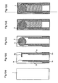
- FIG 1 is an exploded diagram illustrating a process of manufacturing the sensor for measuring a blood sugar level, and the same parts as those in the conventional constitution shown in figure 3 are denoted by the same reference numerals.
- conductive lead parts 2 and 3 are formed of a metal material such as silver paste on a substrate 1 as in the conventional process.
- end parts 2b and 3b of the conductive lead parts 2 and 3 are not shaped to follow a working electrode and a counter electrode as conventional but are merely closed in straight lines.
- a working electrode 4 and a counter electrode 5, which are larger than prescribed shapes, are formed so as to partially overlap the end parts 2b and 3b of the lead parts, employing carbon paste which is mainly composed of carbon.
- An insulating paste is overprinted on the substrate 1 of this state so as to expose the working electrode 4, the counter electrode 5, and the connection terminals 2a and 3a, thereby forming an insulating layer 6. At this time, portions of the working electrode 4 and the counter electrode 5 formed on the end parts 2b and 3b of the conductive lead parts are covered with the insulating layer 6.
- a prescribed reagent reaction layer 7 which includes a hydrophilic polymer (carboxymethyl cellulose), an enzyme (glucose oxidase), and an electron acceptor (potassium ferricyanide) is formed on the electrodes 4 and 5 constructed as described above. At this time, even when the reaction layer 7 is extensively formed over the portions of the working electrode 4 and counter electrode 5 formed on the end parts 2b and 3b of the conductive lead parts, since these portions are covered with the insulating layer 6, the reaction layer 7 never comes in contact with the portions of the working electrode 4 and the counter electrode 5. That is, the reaction layer 7 is not substantially provided on the portions of the working electrode 4 and the counter electrode 5.
- a cover 9 having a specimen supply groove 10 is adhered as in the conventional process, and also at this time, the specimen supply groove 10 is never positioned above the portions of the end parts 2b and 3b of the conductive lead parts.
- Figure 2 illustrates a result obtained when purified water is measured (blank value) by the sensor of the above-described constitution, which is preserved in a hostile environment where the temperature is 40°C and the humidity is 80%. An average at ten measurements is plotted, and it is shown that increase in blank value can be suppressed even in a hostile environment of high temperature and humidity.
- Table 1 shows a comparison of sensor accuracy at twenty measurements with the blood glucose concentration of 42 ⁇ 600mg/dl.
- the sensor accuracy is detected as follows. A reaction between a reagent and glucose in the blood is promoted for about twenty-five seconds after the blood is drawn into the capillary and, thereafter, a voltage of 0.5 V is applied between the connection terminal 2a of the working electrode and the connection terminal 3a of the counter electrode, and an electric current value is obtained five seconds later. The accuracy of variation in the electric current value is referred to as the sensor accuracy.
- the variation in measurement of the sensor according to this embodiment is significantly decreased and reduced as compared with that of the conventional sensor.
- a biosensor according to the present invention can speedily determine the quantity of measurement target substance in a specimen liquid, thereby providing a biosensor which operates in high quality even in a high-humidity environment.
Abstract
Description
- The present invention relates to a biosensor and a method for manufacturing the biosensor and, more particularly, to a biosensor which can speedily determine the quantity of a measurement target substance in a specimen liquid, and a method for manufacturing the biosensor.
-
US-A-5-512 159 discloses a conventional biosensor for measuring a specific measurement target substance in a specimen liquid, which measures an electric current value obtained by a reaction between glucose in blood and a reagent such as glucose oxidase, potassium ferricyanide, or the like supported in the sensor, thereby to obtain a blood sugar level. -
Figure 3 is an exploded diagram illustrating a process of manufacturing said conventional biosensor for measuring a blood sugar level. - A pair of
conductive lead parts terminals film insulating substrate 1 comprising polyethylene terephthalate or the like by screen printing or the like employing silver paste.End parts conductive lead parts end part 2b of theconductive lead 2 is formed into a rectangle shape and theend part 3b of theconductive lead 3 is formed into a shape surrounding the rectangular shape. Then, a working electrode 4 and acounter electrode 5 of prescribed shapes are formed so as to overlap therespective end parts - Next, an insulating paste is overprinted on the
insulating substrate 1 so as to expose the working electrode 4, thecounter electrode 5, and theconnection terminals insulating layer 6. A reaction layer 7, which includes carboxymethyl cellulose as a hydrophilic polymer, glucose oxidase as an enzyme, and potassium ferricyanide as an electron acceptor, is formed on the exposed working electrode 4 andcounter electrode 5 so as to bridge theseelectrodes 4 and 5. - Thereafter, a cover, onto the reverse side of which a spacer 8 with a spindly
specimen supply groove 10 having an opening part at its end formed is attached, is adhered so that an end part of thespecimen supply groove 10 is located on the reaction layer 7, so as to cover the reaction layer 7 with theconnection terminals figure 4 . Numeral 11 denotes an air vent formed at the end part of thespecimen supply groove 10. - When the sensor constructed as described above is connected to a measuring device and a blood sample to be measured is touched to the opening of the
specimen supply groove 10, a prescribed amount of sample is introduced into the reaction layer 7 through thespecimen supply groove 10 by a capillary phenomenon, and a prescribed reaction between the glucose in the blood and the glucose oxidase as well as potassium ferricyanide supported in the sensor is developed. Then, an electric current value accompanying the reaction is read on the measuring device side through theconnection terminals - However, in the case of the above-described conventional biosensor, the working electrode 4 and the
counter electrode 5 are formed by overprinting carbon electrodes having almost the same shapes as theend parts counter electrode 5 are exposed to the surface to come into contact with the potassium ferricyanide which is the electron acceptor in the reaction layer 7, resulting in increase in blank value and degradation of CV value (complete blood accuracy). - Further, regarding the working electrode, increase in blank value and degradation of CV value occur due to an oxidation current of silver, resulting in degradation of sensor accuracy. Since the above-described problems have larger influences in a high-humidity environment, preservation in a dry condition is indispensable.
- In order to solve the above-described problems, a biosensor according to the present invention is characterized by that the reaction layer which contacts the electrodes is not provided above at least one of the conductive lead parts, and even when a pin hole or a crack is generated in the both electrodes above the conductive lead parts, since the reaction layer is not provided in contact with the both electrodes in that portion, potassium ferricyanide and the conductive lead parts never contact. Further, an oxidation current of silver can be prevented at the working electrode, thereby providing a high-quality biosensor even in a high-humidity environment.
- As described above, according to the invention, even when a pin hole or a crack is generated in the working electrode or the counter electrode, the electron acceptor, such as potassium ferricyanide, does not contact the conductive lead part, and further, an oxidation current of the lead part, which is made of a metal such as silver, can be completely prevented at the working electrode, whereby a high-quality biosensor which is excellent in preservation stability even in a high-humidity environment can be provided.
-
-
Figure 1 is an exploded diagram illustrating a process of manufacturing a sensor for measuring a blood sugar level according to an embodiment of the present invention. -
Figure 2 is a diagram illustrating a comparison of CV values between the sensor for measuring a blood sugar level according to the embodiment of the invention and the conventional sensor for measuring a blood sugar level. -
Figure 3 is an exploded diagram illustrating a process of manufacturing the conventional sensor for measuring a blood sugar level. -
Figure 4 is an exploded perspective view of the conventional sensor for measuring a blood sugar level. - Hereinafter, a sensor for measuring a blood sugar level according to an embodiment of the present invention will be described with reference to
figure 1. Figure 1 is an exploded diagram illustrating a process of manufacturing the sensor for measuring a blood sugar level, and the same parts as those in the conventional constitution shown infigure 3 are denoted by the same reference numerals. - First of all,
conductive lead parts substrate 1 as in the conventional process. A difference from the conventional process is thatend parts conductive lead parts counter electrode 5, which are larger than prescribed shapes, are formed so as to partially overlap theend parts - An insulating paste is overprinted on the
substrate 1 of this state so as to expose the working electrode 4, thecounter electrode 5, and theconnection terminals insulating layer 6. At this time, portions of the working electrode 4 and thecounter electrode 5 formed on theend parts layer 6. - A prescribed reagent reaction layer 7 which includes a hydrophilic polymer (carboxymethyl cellulose), an enzyme (glucose oxidase), and an electron acceptor (potassium ferricyanide) is formed on the
electrodes 4 and 5 constructed as described above. At this time, even when the reaction layer 7 is extensively formed over the portions of the working electrode 4 andcounter electrode 5 formed on theend parts insulating layer 6, the reaction layer 7 never comes in contact with the portions of the working electrode 4 and thecounter electrode 5. That is, the reaction layer 7 is not substantially provided on the portions of the working electrode 4 and thecounter electrode 5. - Thereafter, a
cover 9 having aspecimen supply groove 10 is adhered as in the conventional process, and also at this time, thespecimen supply groove 10 is never positioned above the portions of theend parts -
Figure 2 illustrates a result obtained when purified water is measured (blank value) by the sensor of the above-described constitution, which is preserved in a hostile environment where the temperature is 40°C and the humidity is 80%. An average at ten measurements is plotted, and it is shown that increase in blank value can be suppressed even in a hostile environment of high temperature and humidity. - (Table 1) shows a comparison of sensor accuracy at twenty measurements with the blood glucose concentration of 42~ 600mg/dl. The sensor accuracy is detected as follows. A reaction between a reagent and glucose in the blood is promoted for about twenty-five seconds after the blood is drawn into the capillary and, thereafter, a voltage of 0.5 V is applied between the
connection terminal 2a of the working electrode and theconnection terminal 3a of the counter electrode, and an electric current value is obtained five seconds later. The accuracy of variation in the electric current value is referred to as the sensor accuracy. The variation in measurement of the sensor according to this embodiment is significantly decreased and reduced as compared with that of the conventional sensor.(Table 1) Glucose concentration Conventional sensor Sensor of embodiment 42mg/dl 7.63% 4.20% 79mg/dl 3.47% 2.75% 245mg/dl 2.60% 2.31% 361mg/dl 2.45% 2.20% 497mg/dl 2.17% 1.64% 600mg/dl 3.81% 1.40% - As seen from
figure 2 and the result of (Table 1), a biosensor which is excellent in preservation stability, is high in sensitivity, and has less variation can be realized by employing the sensor of the embodiment. - While a sensor for measuring a blood sugar level is exemplified in this embodiment, the same effects can be achieved even in a similarly constituted sensor for measuring cholesterol, lactic acid, or the like. Further, while it is most desirable that there is no reaction layer on the lead parts on both of the working electrode and the counter electrode, the same effects can be also achieved when there is no reaction layer on either one of them.
- As described above, a biosensor according to the present invention can speedily determine the quantity of measurement target substance in a specimen liquid, thereby providing a biosensor which operates in high quality even in a high-humidity environment.
Claims (4)
- A biosensor comprising:a pair of conductive lead parts (2, 3) formed on an insulating substrate (1), said conductive lead parts (2, 3) being formed of a metal;a working electrode (4) formed at an end (2b) of one of the conductive lead parts on the substrate so that a portion of the working electrode (4) overlaps the conductive lead part (2), said working electrode being formed of a material mainly composed of carbon;a counter electrode (5) formed at an end (3b) of the other conductive lead part on the substrate so that a portion of the counter electrode (5) overlaps the conductive lead part (3), said counter electrode being formed of a material mainly composed of carbon; anda reaction layer (7) which is formed on the working electrode (4) and the counter electrode (5) so as to bridge the both electrodes and reacts with a measurement target substance in a specimen liquid; andthe biosensor measuring the content of the measurement target substance, from an electric current value based on the reaction between the measurement target substance and the reaction layer, which current value is obtained through the pair of conductive lead parts;characterized in thatthe end parts (2b, 3b) are closed in straight lines, andportions of the working electrode (4) and the counter electrode (5) formed on the end parts (2b, 3b) of the conductive lead parts (2, 3) are covered with an insulating layer (6),whereby the reaction layer (7) which contacts the electrodes (4, 5) is not provided above at least one of the conductive lead parts (2, 3).
- A biosensor as defined in Claim 1, wherein the reaction layer part is covered with a cover (9) having a specimen supply groove (10) which has an opening at an end and introduces a specimen liquid applied around the opening to the reaction layer, and the conductive lead parts are not located beneath the specimen supply groove.
- A biosensor as defined in Claim 1, wherein the reaction layer (7) includes at least an enzyme and an electron acceptor.
- A biosensor manufacturing method comprising:forming a pair of conductive lead parts (2, 3) having end parts (2b, 3b) closed in straight lines on an insulating substrate (1), wherein said conductive lead parts (2, 3) are formed of a paste mainly composed of a metal;forming a working electrode (4) on the insulating substrate (1) so that a portion of the working electrode (4) is continuous to an end (2b) of one of the conductive lead parts, and forming a counter electrode (5) so that a portion of the counter electrode is continuous to an end (3b) of the other conductive lead part; wherein the working electrode (4) and the counter electrode (5) are formed of a paste mainly composed of carbon;forming an insulating layer (6) so as to cover the portions of the both electrodes (4, 5), which portions are formed on the conductive lead parts (2, 3); andforming a reaction layer (7) which reacts with a measurement target substance in a specimen liquid, on the both electrodes (4, 5) so as to bridge them.
Applications Claiming Priority (3)
| Application Number | Priority Date | Filing Date | Title |
|---|---|---|---|
| JP2000062855 | 2000-03-08 | ||
| JP2000062855A JP3985417B2 (en) | 2000-03-08 | 2000-03-08 | Biosensor and manufacturing method thereof |
| PCT/JP2001/001812 WO2001067081A1 (en) | 2000-03-08 | 2001-03-08 | Biosensor and method of producing the same |
Publications (3)
| Publication Number | Publication Date |
|---|---|
| EP1182451A1 EP1182451A1 (en) | 2002-02-27 |
| EP1182451A4 EP1182451A4 (en) | 2003-06-25 |
| EP1182451B1 true EP1182451B1 (en) | 2011-08-03 |
Family
ID=18582811
Family Applications (1)
| Application Number | Title | Priority Date | Filing Date |
|---|---|---|---|
| EP01912188A Expired - Lifetime EP1182451B1 (en) | 2000-03-08 | 2001-03-08 | Biosensor and method of producing the same |
Country Status (5)
| Country | Link |
|---|---|
| US (1) | US6860978B2 (en) |
| EP (1) | EP1182451B1 (en) |
| JP (1) | JP3985417B2 (en) |
| CN (1) | CN1182388C (en) |
| WO (1) | WO2001067081A1 (en) |
Families Citing this family (19)
| Publication number | Priority date | Publication date | Assignee | Title |
|---|---|---|---|---|
| US8071384B2 (en) | 1997-12-22 | 2011-12-06 | Roche Diagnostics Operations, Inc. | Control and calibration solutions and methods for their use |
| US20050103624A1 (en) * | 1999-10-04 | 2005-05-19 | Bhullar Raghbir S. | Biosensor and method of making |
| AU2002356956A1 (en) * | 2001-11-16 | 2003-06-10 | North Carolina State University | Biomedical electrochemical sensor array and method of fabrication |
| GB0211449D0 (en) * | 2002-05-17 | 2002-06-26 | Oxford Biosensors Ltd | Analyte measurement |
| PT1639352T (en) | 2003-06-20 | 2018-07-09 | Hoffmann La Roche | Method and reagent for producing narrow, homogenous reagent strips |
| US7718439B2 (en) | 2003-06-20 | 2010-05-18 | Roche Diagnostics Operations, Inc. | System and method for coding information on a biosensor test strip |
| US8148164B2 (en) | 2003-06-20 | 2012-04-03 | Roche Diagnostics Operations, Inc. | System and method for determining the concentration of an analyte in a sample fluid |
| US8071030B2 (en) * | 2003-06-20 | 2011-12-06 | Roche Diagnostics Operations, Inc. | Test strip with flared sample receiving chamber |
| US7645421B2 (en) | 2003-06-20 | 2010-01-12 | Roche Diagnostics Operations, Inc. | System and method for coding information on a biosensor test strip |
| US8679853B2 (en) * | 2003-06-20 | 2014-03-25 | Roche Diagnostics Operations, Inc. | Biosensor with laser-sealed capillary space and method of making |
| US8058077B2 (en) | 2003-06-20 | 2011-11-15 | Roche Diagnostics Operations, Inc. | Method for coding information on a biosensor test strip |
| US7452457B2 (en) | 2003-06-20 | 2008-11-18 | Roche Diagnostics Operations, Inc. | System and method for analyte measurement using dose sufficiency electrodes |
| US8206565B2 (en) | 2003-06-20 | 2012-06-26 | Roche Diagnostics Operation, Inc. | System and method for coding information on a biosensor test strip |
| US7645373B2 (en) | 2003-06-20 | 2010-01-12 | Roche Diagnostic Operations, Inc. | System and method for coding information on a biosensor test strip |
| US7569126B2 (en) | 2004-06-18 | 2009-08-04 | Roche Diagnostics Operations, Inc. | System and method for quality assurance of a biosensor test strip |
| US20110186428A1 (en) * | 2010-01-29 | 2011-08-04 | Roche Diagnostics Operations, Inc. | Electrode arrangements for biosensors |
| US10041901B2 (en) * | 2013-03-15 | 2018-08-07 | Roche Diabetes Care, Inc. | Electrode configuration for a biosensor |
| US20150068893A1 (en) * | 2013-09-12 | 2015-03-12 | Joinsoon Medical Technology Co., Ltd. | Biosensor test strip for biosensor test device |
| CN109916983B (en) * | 2019-03-27 | 2020-04-10 | 南京腾森分析仪器有限公司 | Three-electrode system, electrochemical sensor and preparation method thereof, electrochemical workstation and application thereof |
Family Cites Families (5)
| Publication number | Priority date | Publication date | Assignee | Title |
|---|---|---|---|---|
| JP3084877B2 (en) | 1992-01-21 | 2000-09-04 | 松下電器産業株式会社 | Manufacturing method of glucose sensor |
| KR970001146B1 (en) * | 1993-07-16 | 1997-01-29 | 엘지전자 주식회사 | Gas measuring bio-sensor and manufacturing method |
| JP3518932B2 (en) | 1995-06-23 | 2004-04-12 | 松下電器産業株式会社 | Biosensor |
| JP3460183B2 (en) * | 1996-12-24 | 2003-10-27 | 松下電器産業株式会社 | Biosensor |
| JP3505978B2 (en) * | 1997-09-26 | 2004-03-15 | Nok株式会社 | Biosensor |
-
2000
- 2000-03-08 JP JP2000062855A patent/JP3985417B2/en not_active Expired - Lifetime
-
2001
- 2001-03-08 CN CNB018004741A patent/CN1182388C/en not_active Expired - Lifetime
- 2001-03-08 EP EP01912188A patent/EP1182451B1/en not_active Expired - Lifetime
- 2001-03-08 WO PCT/JP2001/001812 patent/WO2001067081A1/en active Application Filing
- 2001-03-08 US US09/959,816 patent/US6860978B2/en not_active Expired - Lifetime
Also Published As
| Publication number | Publication date |
|---|---|
| CN1364234A (en) | 2002-08-14 |
| EP1182451A1 (en) | 2002-02-27 |
| CN1182388C (en) | 2004-12-29 |
| JP2001255297A (en) | 2001-09-21 |
| JP3985417B2 (en) | 2007-10-03 |
| US6860978B2 (en) | 2005-03-01 |
| US20020179441A1 (en) | 2002-12-05 |
| EP1182451A4 (en) | 2003-06-25 |
| WO2001067081A1 (en) | 2001-09-13 |
Similar Documents
| Publication | Publication Date | Title |
|---|---|---|
| EP1182451B1 (en) | Biosensor and method of producing the same | |
| US7297248B2 (en) | Glucose strip sensor and glucose measurement method using the glucose strip sensor | |
| JP3084877B2 (en) | Manufacturing method of glucose sensor | |
| CN1163742C (en) | Biological sensor | |
| KR101566256B1 (en) | Electrochemical test strip | |
| JP3842989B2 (en) | Biosensor with chromatographic porous thin film | |
| US6416641B1 (en) | Biosensor | |
| US5565085A (en) | Method for quantifying specific compound | |
| EP1155310B1 (en) | Disposable test strips with integrated reagent/blood separation layer | |
| KR100475634B1 (en) | Biosensor equipped with sample introducing part which enables quick introduction of a small amount of sample | |
| WO2020094082A1 (en) | Potentiometric biosensor and detection method | |
| CN113049652B (en) | Electrochemical measurement method | |
| JP4404433B2 (en) | Disposable BUN sensor and manufacturing method thereof | |
| JP2003014684A (en) | Biosensor and its measurement sensitivity controlling method | |
| US20180231490A1 (en) | Method for calculating hematocrit in blood, method for calibrating biochemical index value in blood, and system thereof | |
| AU2017204379B2 (en) | Electrochemical test strip | |
| JP2004004057A (en) | Biosensor, adapter used for the same and measuring apparatus | |
| JPH0375552A (en) | Enzyme electrode | |
| KR20150111100A (en) | Electrochemical biosensor strip | |
| AU2013204842B2 (en) | Electrochemical test strip |
Legal Events
| Date | Code | Title | Description |
|---|---|---|---|
| PUAI | Public reference made under article 153(3) epc to a published international application that has entered the european phase |
Free format text: ORIGINAL CODE: 0009012 |
|
| 17P | Request for examination filed |
Effective date: 20011127 |
|
| AK | Designated contracting states |
Kind code of ref document: A1 Designated state(s): AT BE CH CY DE DK ES FI FR GB GR IE IT LI LU MC NL PT SE TR |
|
| AX | Request for extension of the european patent |
Free format text: AL;LT;LV;MK;RO;SI |
|
| A4 | Supplementary search report drawn up and despatched |
Effective date: 20030513 |
|
| RIC1 | Information provided on ipc code assigned before grant |
Ipc: 7G 01N 27/327 A Ipc: 7G 01N 33/487 B Ipc: 7C 12Q 1/00 B |
|
| RBV | Designated contracting states (corrected) |
Designated state(s): DE FR GB IT |
|
| 17Q | First examination report despatched |
Effective date: 20080204 |
|
| RAP1 | Party data changed (applicant data changed or rights of an application transferred) |
Owner name: PANASONIC CORPORATION |
|
| GRAP | Despatch of communication of intention to grant a patent |
Free format text: ORIGINAL CODE: EPIDOSNIGR1 |
|
| GRAS | Grant fee paid |
Free format text: ORIGINAL CODE: EPIDOSNIGR3 |
|
| GRAA | (expected) grant |
Free format text: ORIGINAL CODE: 0009210 |
|
| AK | Designated contracting states |
Kind code of ref document: B1 Designated state(s): DE FR GB IT |
|
| REG | Reference to a national code |
Ref country code: GB Ref legal event code: FG4D |
|
| REG | Reference to a national code |
Ref country code: DE Ref legal event code: R096 Ref document number: 60145072 Country of ref document: DE Effective date: 20110929 |
|
| PLBE | No opposition filed within time limit |
Free format text: ORIGINAL CODE: 0009261 |
|
| STAA | Information on the status of an ep patent application or granted ep patent |
Free format text: STATUS: NO OPPOSITION FILED WITHIN TIME LIMIT |
|
| 26N | No opposition filed |
Effective date: 20120504 |
|
| REG | Reference to a national code |
Ref country code: DE Ref legal event code: R097 Ref document number: 60145072 Country of ref document: DE Effective date: 20120504 |
|
| REG | Reference to a national code |
Ref country code: DE Ref legal event code: R082 Ref document number: 60145072 Country of ref document: DE Representative=s name: EISENFUEHR SPEISER PATENTANWAELTE RECHTSANWAEL, DE |
|
| REG | Reference to a national code |
Ref country code: GB Ref legal event code: 732E Free format text: REGISTERED BETWEEN 20140313 AND 20140319 |
|
| REG | Reference to a national code |
Ref country code: DE Ref legal event code: R081 Ref document number: 60145072 Country of ref document: DE Owner name: PANASONIC CORPORATION, JP Free format text: FORMER OWNER: PANASONIC CORPORATION, KADOMA, JP Effective date: 20140324 Ref country code: DE Ref legal event code: R081 Ref document number: 60145072 Country of ref document: DE Owner name: PANASONIC CORPORATION, JP Free format text: FORMER OWNER: PANASONIC HEALTHCARE CO., LTD., TOON-SHI, JP Effective date: 20140404 Ref country code: DE Ref legal event code: R082 Ref document number: 60145072 Country of ref document: DE Representative=s name: EISENFUEHR SPEISER PATENTANWAELTE RECHTSANWAEL, DE Effective date: 20140404 Ref country code: DE Ref legal event code: R082 Ref document number: 60145072 Country of ref document: DE Representative=s name: EISENFUEHR SPEISER PATENTANWAELTE RECHTSANWAEL, DE Effective date: 20140324 Ref country code: DE Ref legal event code: R081 Ref document number: 60145072 Country of ref document: DE Owner name: PANASONIC CORPORATION, JP Free format text: FORMER OWNER: MATSUSHITA ELECTRIC INDUSTRIAL CO., LTD., KADOMA-SHI, JP Effective date: 20110808 Ref country code: DE Ref legal event code: R081 Ref document number: 60145072 Country of ref document: DE Owner name: PANASONIC HEALTHCARE HOLDINGS CO., LTD., JP Free format text: FORMER OWNER: PANASONIC HEALTHCARE CO., LTD., TOON-SHI, EHIME, JP Effective date: 20140404 Ref country code: DE Ref legal event code: R081 Ref document number: 60145072 Country of ref document: DE Owner name: PANASONIC HEALTHCARE HOLDINGS CO., LTD., JP Free format text: FORMER OWNER: MATSUSHITA ELECTRIC INDUSTRIAL CO., LTD., KADOMA-SHI, OSAKA, JP Effective date: 20110808 Ref country code: DE Ref legal event code: R081 Ref document number: 60145072 Country of ref document: DE Owner name: PANASONIC HEALTHCARE HOLDINGS CO., LTD., JP Free format text: FORMER OWNER: PANASONIC CORPORATION, KADOMA, OSAKA, JP Effective date: 20140324 |
|
| REG | Reference to a national code |
Ref country code: GB Ref legal event code: 732E Free format text: REGISTERED BETWEEN 20140814 AND 20140820 |
|
| REG | Reference to a national code |
Ref country code: DE Ref legal event code: R082 Ref document number: 60145072 Country of ref document: DE Representative=s name: EISENFUEHR SPEISER PATENTANWAELTE RECHTSANWAEL, DE |
|
| REG | Reference to a national code |
Ref country code: FR Ref legal event code: TP Owner name: PANASONIC HEALTHCARE HOLDINGS CO., LTD., JP Effective date: 20140827 Ref country code: FR Ref legal event code: CA Effective date: 20140827 |
|
| REG | Reference to a national code |
Ref country code: GB Ref legal event code: 732E Free format text: REGISTERED BETWEEN 20141002 AND 20141008 |
|
| REG | Reference to a national code |
Ref country code: DE Ref legal event code: R082 Ref document number: 60145072 Country of ref document: DE Representative=s name: EISENFUEHR SPEISER PATENTANWAELTE RECHTSANWAEL, DE Effective date: 20140925 Ref country code: DE Ref legal event code: R081 Ref document number: 60145072 Country of ref document: DE Owner name: PANASONIC HEALTHCARE HOLDINGS CO., LTD., JP Free format text: FORMER OWNER: PANASONIC CORPORATION, KADOMA-SHI, OSAKA, JP Effective date: 20140925 |
|
| REG | Reference to a national code |
Ref country code: FR Ref legal event code: TP Owner name: PANASONIC HEALTHCARE HOLDINGS CO., LTD., JP Effective date: 20141008 |
|
| REG | Reference to a national code |
Ref country code: FR Ref legal event code: CD Owner name: PANASONIC HEALTHCARE HOLDINGS CO., LTD., JP Effective date: 20141218 Ref country code: FR Ref legal event code: TP Owner name: PANASONIC HEALTHCARE HOLDINGS CO., LTD., JP Effective date: 20141218 Ref country code: FR Ref legal event code: CA Effective date: 20141218 |
|
| REG | Reference to a national code |
Ref country code: FR Ref legal event code: PLFP Year of fee payment: 16 |
|
| REG | Reference to a national code |
Ref country code: FR Ref legal event code: PLFP Year of fee payment: 17 |
|
| REG | Reference to a national code |
Ref country code: FR Ref legal event code: PLFP Year of fee payment: 18 |
|
| REG | Reference to a national code |
Ref country code: DE Ref legal event code: R082 Ref document number: 60145072 Country of ref document: DE Representative=s name: EISENFUEHR SPEISER PATENTANWAELTE RECHTSANWAEL, DE Ref country code: DE Ref legal event code: R081 Ref document number: 60145072 Country of ref document: DE Owner name: PHC HOLDINGS CORP., JP Free format text: FORMER OWNER: PANASONIC HEALTHCARE HOLDINGS CO., LTD., TOKIO, JP |
|
| PGFP | Annual fee paid to national office [announced via postgrant information from national office to epo] |
Ref country code: IT Payment date: 20200221 Year of fee payment: 20 Ref country code: GB Payment date: 20200226 Year of fee payment: 20 Ref country code: DE Payment date: 20200225 Year of fee payment: 20 |
|
| PGFP | Annual fee paid to national office [announced via postgrant information from national office to epo] |
Ref country code: FR Payment date: 20200214 Year of fee payment: 20 |
|
| REG | Reference to a national code |
Ref country code: DE Ref legal event code: R071 Ref document number: 60145072 Country of ref document: DE |
|
| REG | Reference to a national code |
Ref country code: GB Ref legal event code: PE20 Expiry date: 20210307 |
|
| PG25 | Lapsed in a contracting state [announced via postgrant information from national office to epo] |
Ref country code: GB Free format text: LAPSE BECAUSE OF EXPIRATION OF PROTECTION Effective date: 20210307 |