EP1171060B1 - Aortic annuloplasty ring - Google Patents
Aortic annuloplasty ring Download PDFInfo
- Publication number
- EP1171060B1 EP1171060B1 EP00922216A EP00922216A EP1171060B1 EP 1171060 B1 EP1171060 B1 EP 1171060B1 EP 00922216 A EP00922216 A EP 00922216A EP 00922216 A EP00922216 A EP 00922216A EP 1171060 B1 EP1171060 B1 EP 1171060B1
- Authority
- EP
- European Patent Office
- Prior art keywords
- prosthesis
- valve
- annulus
- upper edge
- aortic
- Prior art date
- Legal status (The legal status is an assumption and is not a legal conclusion. Google has not performed a legal analysis and makes no representation as to the accuracy of the status listed.)
- Expired - Lifetime
Links
- 239000000560 biocompatible material Substances 0.000 claims description 8
- 210000003709 heart valve Anatomy 0.000 claims description 3
- 229920000728 polyester Polymers 0.000 claims description 3
- 229910000531 Co alloy Inorganic materials 0.000 claims description 2
- QXZUUHYBWMWJHK-UHFFFAOYSA-N [Co].[Ni] Chemical compound [Co].[Ni] QXZUUHYBWMWJHK-UHFFFAOYSA-N 0.000 claims description 2
- 239000004033 plastic Substances 0.000 claims description 2
- 229920003023 plastic Polymers 0.000 claims description 2
- 210000001765 aortic valve Anatomy 0.000 description 11
- 239000000463 material Substances 0.000 description 11
- 238000000034 method Methods 0.000 description 10
- 239000008280 blood Substances 0.000 description 9
- 210000004369 blood Anatomy 0.000 description 9
- 238000004873 anchoring Methods 0.000 description 7
- 210000001367 artery Anatomy 0.000 description 7
- 230000002685 pulmonary effect Effects 0.000 description 6
- 238000000926 separation method Methods 0.000 description 6
- 210000004115 mitral valve Anatomy 0.000 description 5
- 229940058401 polytetrafluoroethylene Drugs 0.000 description 5
- 229920001343 polytetrafluoroethylene Polymers 0.000 description 5
- 239000004810 polytetrafluoroethylene Substances 0.000 description 5
- 235000014676 Phragmites communis Nutrition 0.000 description 4
- 206010067171 Regurgitation Diseases 0.000 description 4
- 210000000709 aorta Anatomy 0.000 description 4
- 238000002513 implantation Methods 0.000 description 4
- 210000003102 pulmonary valve Anatomy 0.000 description 4
- 230000008439 repair process Effects 0.000 description 4
- 230000008901 benefit Effects 0.000 description 3
- 230000000747 cardiac effect Effects 0.000 description 3
- 238000010276 construction Methods 0.000 description 3
- 230000004064 dysfunction Effects 0.000 description 3
- 210000005240 left ventricle Anatomy 0.000 description 3
- 230000003387 muscular Effects 0.000 description 3
- 238000010168 coupling process Methods 0.000 description 2
- 230000010339 dilation Effects 0.000 description 2
- 239000004744 fabric Substances 0.000 description 2
- 238000004519 manufacturing process Methods 0.000 description 2
- 239000002184 metal Substances 0.000 description 2
- 229910052751 metal Inorganic materials 0.000 description 2
- 239000000203 mixture Substances 0.000 description 2
- -1 polytetrafluoro-ethylene Polymers 0.000 description 2
- 210000005241 right ventricle Anatomy 0.000 description 2
- 210000000591 tricuspid valve Anatomy 0.000 description 2
- 229920000049 Carbon (fiber) Polymers 0.000 description 1
- MWCLLHOVUTZFKS-UHFFFAOYSA-N Methyl cyanoacrylate Chemical compound COC(=O)C(=C)C#N MWCLLHOVUTZFKS-UHFFFAOYSA-N 0.000 description 1
- 238000012331 Postoperative analysis Methods 0.000 description 1
- 208000012287 Prolapse Diseases 0.000 description 1
- 230000002159 abnormal effect Effects 0.000 description 1
- 230000009471 action Effects 0.000 description 1
- 230000002411 adverse Effects 0.000 description 1
- 230000001174 ascending effect Effects 0.000 description 1
- 230000009286 beneficial effect Effects 0.000 description 1
- 239000004917 carbon fiber Substances 0.000 description 1
- 239000011248 coating agent Substances 0.000 description 1
- 238000000576 coating method Methods 0.000 description 1
- 230000006835 compression Effects 0.000 description 1
- 238000007906 compression Methods 0.000 description 1
- 230000008602 contraction Effects 0.000 description 1
- 230000008878 coupling Effects 0.000 description 1
- 238000005859 coupling reaction Methods 0.000 description 1
- 238000002788 crimping Methods 0.000 description 1
- 230000007547 defect Effects 0.000 description 1
- 230000003205 diastolic effect Effects 0.000 description 1
- 230000000694 effects Effects 0.000 description 1
- 229910000701 elgiloys (Co-Cr-Ni Alloy) Inorganic materials 0.000 description 1
- 150000002739 metals Chemical class 0.000 description 1
- VNWKTOKETHGBQD-UHFFFAOYSA-N methane Chemical compound C VNWKTOKETHGBQD-UHFFFAOYSA-N 0.000 description 1
- 210000001147 pulmonary artery Anatomy 0.000 description 1
- 230000003252 repetitive effect Effects 0.000 description 1
- 239000007787 solid Substances 0.000 description 1
- 239000000126 substance Substances 0.000 description 1
- 229910000811 surgical stainless steel Inorganic materials 0.000 description 1
- 238000003466 welding Methods 0.000 description 1
- 239000002759 woven fabric Substances 0.000 description 1
Images

Classifications
-
- A—HUMAN NECESSITIES
- A61—MEDICAL OR VETERINARY SCIENCE; HYGIENE
- A61F—FILTERS IMPLANTABLE INTO BLOOD VESSELS; PROSTHESES; DEVICES PROVIDING PATENCY TO, OR PREVENTING COLLAPSING OF, TUBULAR STRUCTURES OF THE BODY, e.g. STENTS; ORTHOPAEDIC, NURSING OR CONTRACEPTIVE DEVICES; FOMENTATION; TREATMENT OR PROTECTION OF EYES OR EARS; BANDAGES, DRESSINGS OR ABSORBENT PADS; FIRST-AID KITS
- A61F2/00—Filters implantable into blood vessels; Prostheses, i.e. artificial substitutes or replacements for parts of the body; Appliances for connecting them with the body; Devices providing patency to, or preventing collapsing of, tubular structures of the body, e.g. stents
- A61F2/02—Prostheses implantable into the body
- A61F2/24—Heart valves ; Vascular valves, e.g. venous valves; Heart implants, e.g. passive devices for improving the function of the native valve or the heart muscle; Transmyocardial revascularisation [TMR] devices; Valves implantable in the body
- A61F2/2442—Annuloplasty rings or inserts for correcting the valve shape; Implants for improving the function of a native heart valve
- A61F2/2445—Annuloplasty rings in direct contact with the valve annulus
Definitions
- the present invention relates generally to valvuloplasty prostheses, and more particularly to biocompatible rings for constricting and restoring the annulus of a natural aortic or pulmonary trileaflet valve.
- the aortic and pulmonary valves are located respectively in the left and right ventricles of the heart. They serve to prevent regurgitation of blood from the aortic artery or pulmonary artery into its associated ventricle when that ventricle is in its expanded state. Both valves consist of three semicircular leaflets or flaps attached by their convex margins to the wall of the artery at its junction into the ventricle. In both the aortic and pulmonary valves, the straight border of each leaflet is free and directed upward into the artery.
- the aortic (left ventricle) valve is larger, thicker and stronger than the pulmonary (right ventricle) valve
- the openings of both arteries into their ventricles are generally circular, and form an annulus or ring that is composed of fibrous rather than muscular tissue.
- Another characteristic shared by these valves is the presence of pouches or sinuses one behind each leaflet, that exist between the valve and the wall of the artery. The blood, in its regurgitation back toward the ventricle, finds its way into these sinuses, and so closes the valve-flaps.
- Healthy functioning valves such as, for example, the aortic valve require a secure meeting of the leaflet free borders along the lines at which they come together. When these free borders securely meet so that no blood can escape back into the ventricle, this positive closing of the leaflets is called coapting.
- the regions extending along and adjacent to the arterial wall at which the leaflets "coapt" are called commissures.
- the circular annulus (defining the border between the sinuses of the ascending vessel and the ventricle) provides a firm base ring for the convex margins or "cusps" of the leaflets so that their free borders can meet securely.
- a common defect leading to aortic valve dysfunction is a dilation or stretching of this arterial annulus, and often its associated valve sinuses, preventing positive closure of the attached leaflets and possibly even allowing one or more leaflets to flip over, or "prolapse", toward the ventricle.
- Total valve replacement is one solution to valve dysfunction, but repair of the annulus or sinuses by various techniques, thereby retaining the natural valve, is preferred.
- annular prostheses have been directed to the reconstructing of the atrioventricular mitral bileaflet and tricuspid trileaflet valves whose specific non-circular configurations are not similar to those of the aortic or pulmonary valves. Accordingly, these prior art prostheses are not suitable for the restoring of an aortic or pulmonary annulus because, unlike the circular aortic or pulmonary valve annuluses, a mitral valve or tricuspid valve annulus is decidedly D-shaped.
- the mitral and tricuspid annuluses include straight segments formed of dense tissue so that their arcuate portions are relatively more subject to problem elongation.
- U.S. Patent No. 3,656,185 to Carpentier discloses a mitral valve reconstruction annular prosthesis. It relies on securing its rigid portion to the mitral valve annulus segment, and is not compatible with the circular shape of the aortic annulus which lacks this rigid foundation upon which to anchor the prosthesis. Moreover, such rigid attachment to the annulus tends to detrimentally inhibit the natural movement of the annulus during a cardiac cycle of expansion and contraction.
- Reed utilizes reciprocating members which are sutured to the relatively more dense muscular structure of the mitral or tricuspid annulus as contrasted with the weaker fibrous composition of the aortic annulus.
- the reciprocating members of Reed are configured for implantation below the valve, not for positioning within the artery as would be desirable in order to reconstruct dilated valve sinuses.
- US-A-5104407 discloses an annuloplasty prosthesis for use in restoring the normal circumference of the dilated annulus and sinuses of a natural arterial heart valve having a plurality of natural valve leaflets and a plurality of commisures; said prosthesis covered by a flexible biocompatible material.
- the present invention is directed to an arterial annuloplasty prosthesis used to restore the generally circular shape of a dilated arterial valve annulus in order to produce positive valve closure.
- This invention corrects the dysfunction caused by excessive dilation of the aortic or pulmonary trileaflet valve annulus, while allowing for natural movement of the annulus during the cardiac cycle.
- the apparatus of the present invention does not require complex fabrication, can be made in a variety of desirable diameters and axial heights, and results in a longer-lasting restoration of the dilated annulus.
- the implantation method of this invention is less complicated than that of previous techniques allowing the surgeon to verify the success of the restoration before closure of the incision.
- the discussion herein will be directed to repair of the aortic valve.
- the principles discussed with respect to the restoration of the aortic valve annulus apply equally as well to a pulmonary annulus restoration.
- valves with three leaflets are described, the discussion also applies in principle to those having two leaflets. Accordingly, the present invention is not restricted to the reconstruction of three leaflet aortic valves, but may be applied to any suitable valve having two or more leaflets.
- the present invention is not intended to provide support to elements of transplanted valves, but rather to restore the size and shape of the natural valve annulus.
- a surgeon encountering a dysfunctional yet otherwise competent natural valve having determined by diagnostic means such as echo Doppler that regurgitation of blood into the ventricle is occurring, may decide that the valve leaflets of the valve are not coapting (i.e. meeting in closure) because of excessive elongation of the valve annulus.
- the invention provides an annuloplasty prosthesis for infra-annular use in restoring the normal circumference of the dilated annulus and sinuses of a natural arterial heart valve having a plurality of natural valve leaflets and a plurality of commissures, said prosthesis covered by a flexible biocompatible material and characterised by: an upper edge having a plurality of axially projecting legs, each of said legs corresponding to the location of a commissure of said valve and being sequentially interconnected by arcuate circumferential segments of said upper edge, the upper edge thus defining a series of peaks and valleys formed to follow the contour of the tissue underneath the natural valve leaflets; a lower edge disposed below and substantially adjacent to said upper edge and shaped to conform to the peaks and valleys of upper edge, the lower edge defining a series of peaks and valleys which is less pronounced than that of the upper edge.
- a preferred embodiment provides a flexibly semi-rigid frame having a diameter within the range of normal valve annulus diameters between 17mm and 29mm.
- the frame is dimensioned to conform to the scalloped configuration of the desired or normal circumference of the annulus.
- Each frame employs three legs projecting axially from the frame for suturing support, with the height of the legs depending on the surgeon's choice of infra- or supra-annular implantation. Typically, the surgeon will have available on site a number of such prostheses with a variety of diameters and let heights from which to choose.
- the frame of either embodiment is completely covered by a flexible biocompatible material or fabric.
- This material isolates the frame within the body and facilitates the suturing of the frame to the anchoring fibrous tissues of the heart as opposed to the more rigid muscular tissue of the mitral valve.
- the flexible material should be as thin as possible to avoid overall bulk of the prosthesis and to minimize obstructing the flow of blood from ventricle to artery.
- a suitable flexible covering may be, for example, polytetrafluoro-ethylene (PTFE), polyester such as polyteraphthalate or similar material.
- PTFE polytetrafluoro-ethylene
- polyester such as polyteraphthalate
- flexible coverings other than PTFE may be used as the isolating and anchoring material with or without a PTFE coating.
- a woven fabric is preferable for strength with minimal thickness and is more desirable than, for example, a more bulky double velour.
- the prosthesis includes a one- or two-part frame having scalloped upper and lower edges defining peaks and valleys.
- the upper edge is shaped to follow the contour of the tissue underneath the valve leaflets, and thus supports the leaflets and aortic wall from below.
- the lower edge is similarly scallop-shaped, but with less pronounced peaks and valleys than the upper edge, and is thus shaped to conform to the aortic annulus shape and provide support directly thereto.
- the infra-annular prosthesis utilizes a two-part wire frame, with one part or wireform above the other, and the wireforms maintained in place relative to each other by the flexible covering material.
- the lower wireform is shaped to conform to the normal circumference of the valve annulus and is flexible enough to permit normal annular flexures yet rigid enough to effectively constrict the dilated annulus to a normal diameter.
- the upper wireform has essentially the same diameter as the lower wireform and follows its radial contours, but unlike the lower wireform it is provided with an axially projecting leg corresponding to the location of each valve commissure.
- the legs of the upper wireform project above the lowest point of the prosthesis to a height on the order of 15% to 60% of the prosthesis diameter depending on the surgeon's predetermined or contemporaneous operational requirements, and the legs constitute supports for suturing the covered frame prosthesis to the dense tissue immediately below the commissure-arterial wall intersection.
- the lower wireform provides the main reconstructive presence of a solid ring for constricting the annulus and restoring its normal diameter.
- the present invention advantageously constricts the dilated valve tissue and restores the circular configuration of the aortic annulus while overcoming the problem of excessive rigidity which prevents normal action of the reconstructed tissue.
- the present invention has the advantage of unitary construction as contrasted with known multi-segmented prostheses such as the previously described Reed '446 and Carpentier '498 apparatus which require more complex manufacture, and which are unable to accommodate supra-annular as well as infra-annular implementation.
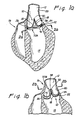
- FIGs. 1a and 1b illustrate the location of a natural aortic trileaflet valve 10 situated at the base of the aorta 12 between aorta 12 and the left ventricle 14 of a heart 16.
- Each of the three valve leaflets 18 is attached to the aortic wall 20 immediately above annulus 22, forming a, generally circular attachment margin 24.
- the circumference of annulus 22 conforms generally to the scalloped shape of the continuous circle segments called sinuses 26 that are disposed immediately above the leaflet attachment margin 24. The relationship between the sinuses and the leaflets is more clearly seen in the plan view of Fig.
- leaflets 18 are shown in the closed (diastolic) position, and when viewed from above as in Fig. 2b, exhibit the coming together or coapting of the free borders 28 of each leaflet 18 at meeting lines called commissures 30.
- FIG. 2a if the normal circumference of annulus 22 becomes elongated so that the annulus 22 and physically related sinuses 26 (Fig. 2b) are dilated, leaflets 18 are unlikely to effect a sufficient closure, resulting in unacceptable regurgitation of blood from aorta 12 past commissures 30 and into ventricle 14.
- a prosthesis that restores the normal circumference of a dilated annulus 22 preferably will also not inhibit the natural movements experienced by the annulus 22 and surrounding tissues during compression (systole) and expansion (diastole) of the heart.
- this restoration can best be accomplished by a flexibly semi-rigid prosthesis that is shaped to conform to the scalloped configuration of the annulus 22 and sinuses 26 combination in its normally undilated condition and is also provided with sufficient flexibility to permit the annular flexures of a regular cardiac cycle.
- Added strength for the prosthesis is achieved by providing suture anchoring points along legs 38 that correspond with the relatively more dense fibrous tissues in the vicinity of commissure 30 intersections with the aortic wall 20.
- FIGs. 1a and 1b illustrate the infra-annular positioning of prosthesis 32A and the supra-annular positioning of prosthesis 32B, respectively.
- prosthesis 32A is shown implanted below annulus 22 where it is sutured (not shown) to tissues within ventricle 14 below natural valve 10.
- Fig. 1b shows prosthesis 32B positioned above natural valve 10, anchored by sutures (not shown) to the walls of aorta 12, and descending into sinuses 26.
- Both embodiments include a flexible annular frame 34 having a scalloped configuration with projecting legs 38 circumferentially spaced to correspond with the location of aortic tissues either below or above the commissures 30 of valve 10.
- a symmetrical spacing of 120° between legs is generally adequate to accommodate the commissure locations of a trileaflet valve.
- each frame is completely covered by a flexible biocompatible material 44 such as woven polyester, or other similarly strong and light material, coated or uncoated, to prevent exposure of the core frame of the prosthesis to living tissue or blood.
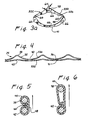
- Prosthesis 32A is shown in Fig. 3 having upper wireform 35 of single wire construction.
- Wireform 35 is formed of flexibly semi-rigid metal, preferably an FDA approved nickel-cobalt alloy such as Elgiloy® having its ends joined at coupling 36 by crimping, welding or other secure coupling process to form an uninterrupted ring having three axially projecting legs 38, one for each commissure 30 intersection of valve 10.
- Each leg 38 is joined to an adjacent leg by curved segments 40 generally following the contours of lower wireform 42, thus defining a circumferentially repetitive frame.
- the frame 34 of the intra-annular prosthesis 32A in Fig. 3 exhibits scalloped upper 33a and lower 33b edges with peaks and valleys.
- the upper edge 33a is shaped to follow the contour of the tissue underneath the valve leaflets, and thus supports the leaflets and aortic wall from below.
- the lower edge 33b is similarly scallop-shaped, but with less pronounced peaks and valleys than the upper edge 33a.
- the lower edge 33b is thus shaped to conform to the aortic annulus shape and provide support directly thereto.
- Lower wireform 42 is of similar single wire construction as upper wireform 35, and shaped to provide continuous reconstructive support along the entire circumference of the dilated valve annulus 22 when prosthesis 32A is implanted below valve 10 and adjacent to annulus 22. While the arcuate circumferential segments 40 of upper wireform 35 follow the beneficial scalloped shape of lower wireform 42, the primary function of upper wireform 35 is to provide anchoring support to lower wireform 42 when legs 38 are sutured to the denser tissues below each commissure 30 connection with aortic wall 20.
- upper and lower wireforms 35 and 42 are more clearly illustrated in the developmental lay-out flat pattern of prosthesis 32A illustrated in Fig. 4.
- Upper legs 38 are shown projecting at regular intervals in correspondence with dense tissue at the commissures that are generally spaced accordingly along the arterial wall, in order to provide anchoring strength to the prosthesis of Fig. 3.
- the arcuate circumferential segments 40 of upper wireform 35 are shown to be in close proximity with the similar circumferential segments 41 of lower wireform 42 along the substantial length of both wireforms, providing support for the annulus-restoring function of lower wireform 42.
- the peaks and valleys of the upper edge 33a are defined by legs 38 and circumferential segments 40 of upper wireform 35
- the peaks and valleys of the lower edge 33b are defined by lower wireform 42.
- the two wireforms 35 and 42 are maintained in place relative to each other by a flexible biocompatible material 44 which also prevents living tissue and blood from making contact with the wireforms.
- the material 44 is preferably as thin as possible to minimize obstruction to the flow of blood through valve 10 and to reduce the overall bulk of prosthesis 32A.
- Fig. 5 taken along line 5-5 of Fig.3 is a cross-section of wireforms 35 and 42 at a point of minimum separation between them. Flexible material 44 is shown to provide the separation of the wireforms by the double-thickness of material at overlap 46 while maintaining the wireforms in proximity to each other along the length 48 of the material.
- Fig. 6 is taken along line 6-6 of Fig.
- FIG. 3 is a sectional view of the wireforms at a point of maximum separation, i.e., showing the tip of a projecting leg 38 and the associated wire form 42 positioned immediately below.
- the vertical separation between leg 38 and lower wireform 42 as shown in Fig. 6 is determined by the fixed height of leg 38 above arcuate segment 40 plus the distance between the wireforms 35 and 42 as illustrated in the developmental layout view of Fig. 4.
- While the two-part wire form structure provides desirable anchoring strength via the upper wire form legs 38, and continuous reconstructive shape via the lower wireform 42 scalloped configuration, alternative single wall structures are within the scope of the present invention, provided they are light in weight and can accommodate a suturing needle. This can be accomplished either through the use of pre-formed holes or by fabricating the structure wall to facilitate piercing by the suturing needle. Suitable substances which may be utilized for fabricating such a single walled structure include strong, light-weight metals such as surgical steel, flexibly rigid plastics such as PTFE, and carbon fiber compositions.
- Fig. 3a illustrates single-walled structure prosthesis 32C showing a typical suture 64 and pre-formed suturing holes 66 disposed about the surface of the structure to provide at least one such hole in each of its three widest portions corresponding to legs 38, and in each of its three narrowest portions corresponding to the arcuate segments 40 and 41 of prosthesis 32A.
- the upper edge 33a is defined by the upper contour of the single-walled prosthesis 32C
- lower edge 33b is defined by the lower contour of the single-walled prosthesis.
- the alternative walled structure 32C of Fig. 3a is surgically implanted below valve 10 in substantially the same manner as is the prosthesis 32A of Fig. 3, with at least one suture passed through each suturing hole 66.
- infra-annular embodiment 32A is put in place from above valve 10 by opening leaflets 18 against aortic wall 20 and lowering the prosthesis through the opened aortic aperture.
- Prosthesis 32A is then nested into the position shown in Fig. 1a by drawing tight the sutures (not shown) taken through fabric material 44 covering each leg 38 and each arcuate segment 40, 41 of the prosthesis.
- the sutures are also taken at corresponding tissue points below the commissures 30 and along the annulus 22, respectively, thereby securing each leg 38 and arcuate segment 40, 41 in place and observably restoring the dilated annulus to its normal circumference.
- any of the annular embodiments of this invention can be fabricated in a variety of diameters and angular placement of projections for custom fitting to the individual application. In general, a range of annular diameters between 17mm and 29mm will suffice for human implantation.
Description
Claims (10)
- An annuloplasty prosthesis (32A, 32C) for infra-annular use in restoring the normal circumference of the dilated annulus and sinuses of a natural arterial heart valve having a plurality of natural valve leaflets and a plurality of commissures, said prosthesis covered by a flexible biocompatible material (44) and characterised by:an upper edge (33a) having a plurality of axially projecting legs (38), each of said legs corresponding to the location of a commissure of said valve and being sequentially interconnected by arcuate circumferential segments (40) of said upper edge, the upper edge thus defining a series of peaks and valleys formed to follow the contour of the tissue underneath the natural valve leaflets;a lower edge (33b) disposed below and substantially adjacent to said upper edge and shaped to conform to the peaks and valleys of upper edge, the lower edge defining a series of peaks and valleys which is less pronounced than that of the upper edge.
- The prosthesis (32A) of Claim 1 comprising: an upper wireform (35) forming the upper edge and a lower wireform forming the lower edge.
- The prosthesis (32A) of Claim 2 wherein said upper and lower wireforms are spaced apart and only connected by the flexible biocompatible material covering (44).
- The prosthesis (32A) of Claim 2 wherein said upper and lower wireforms are metallic.
- The prosthesis (32A) of Claim 4 wherein said upper and lower wireforms are formed of nickel-cobalt alloy.
- The prosthesis of Claim 1 wherein the upper and lower edges (33a, 33b) are defined by a single-walled structure (32C) adapted to be pierced by a suturing needle.
- The prosthesis of Claim 6 wherein said single-walled structure has a plurality of suturing holes (66) disposed about its surface.
- The prosthesis of Claim 7 wherein said single-walled structure (32C) is metallic.
- The prosthesis of Claim 6 wherein said single-walled structure (32C) is plastic.
- The prosthesis of Claim 1 wherein said biocompatible material is woven polyester.
Applications Claiming Priority (3)
| Application Number | Priority Date | Filing Date | Title |
|---|---|---|---|
| US293215 | 1999-04-16 | ||
| US09/293,215 US6231602B1 (en) | 1999-04-16 | 1999-04-16 | Aortic annuloplasty ring |
| PCT/US2000/010105 WO2000062715A1 (en) | 1999-04-16 | 2000-04-14 | Aortic annuloplasty ring |
Publications (2)
| Publication Number | Publication Date |
|---|---|
| EP1171060A1 EP1171060A1 (en) | 2002-01-16 |
| EP1171060B1 true EP1171060B1 (en) | 2005-06-22 |
Family
ID=23128179
Family Applications (1)
| Application Number | Title | Priority Date | Filing Date |
|---|---|---|---|
| EP00922216A Expired - Lifetime EP1171060B1 (en) | 1999-04-16 | 2000-04-14 | Aortic annuloplasty ring |
Country Status (8)
| Country | Link |
|---|---|
| US (1) | US6231602B1 (en) |
| EP (1) | EP1171060B1 (en) |
| JP (1) | JP4174184B2 (en) |
| AU (1) | AU772890B2 (en) |
| BR (1) | BR0010676B1 (en) |
| CA (1) | CA2365358C (en) |
| DE (1) | DE60020950T2 (en) |
| WO (1) | WO2000062715A1 (en) |
Cited By (13)
| Publication number | Priority date | Publication date | Assignee | Title |
|---|---|---|---|---|
| US10856984B2 (en) | 2017-08-25 | 2020-12-08 | Neovasc Tiara Inc. | Sequentially deployed transcatheter mitral valve prosthesis |
| US10940001B2 (en) | 2012-05-30 | 2021-03-09 | Neovasc Tiara Inc. | Methods and apparatus for loading a prosthesis onto a delivery system |
| US11311376B2 (en) | 2019-06-20 | 2022-04-26 | Neovase Tiara Inc. | Low profile prosthetic mitral valve |
| US11357622B2 (en) | 2016-01-29 | 2022-06-14 | Neovase Tiara Inc. | Prosthetic valve for avoiding obstruction of outflow |
| US11389291B2 (en) | 2013-04-04 | 2022-07-19 | Neovase Tiara Inc. | Methods and apparatus for delivering a prosthetic valve to a beating heart |
| US11413139B2 (en) | 2011-11-23 | 2022-08-16 | Neovasc Tiara Inc. | Sequentially deployed transcatheter mitral valve prosthesis |
| US11419720B2 (en) | 2010-05-05 | 2022-08-23 | Neovasc Tiara Inc. | Transcatheter mitral valve prosthesis |
| US11464631B2 (en) | 2016-11-21 | 2022-10-11 | Neovasc Tiara Inc. | Methods and systems for rapid retraction of a transcatheter heart valve delivery system |
| US11491006B2 (en) | 2019-04-10 | 2022-11-08 | Neovasc Tiara Inc. | Prosthetic valve with natural blood flow |
| US11497602B2 (en) | 2012-02-14 | 2022-11-15 | Neovasc Tiara Inc. | Methods and apparatus for engaging a valve prosthesis with tissue |
| US11602429B2 (en) | 2019-04-01 | 2023-03-14 | Neovasc Tiara Inc. | Controllably deployable prosthetic valve |
| US11737872B2 (en) | 2018-11-08 | 2023-08-29 | Neovasc Tiara Inc. | Ventricular deployment of a transcatheter mitral valve prosthesis |
| US11779742B2 (en) | 2019-05-20 | 2023-10-10 | Neovasc Tiara Inc. | Introducer with hemostasis mechanism |
Families Citing this family (351)
| Publication number | Priority date | Publication date | Assignee | Title |
|---|---|---|---|---|
| DK124690D0 (en) * | 1990-05-18 | 1990-05-18 | Henning Rud Andersen | FAT PROTECTION FOR IMPLEMENTATION IN THE BODY FOR REPLACEMENT OF NATURAL FLEET AND CATS FOR USE IN IMPLEMENTING A SUCH FAT PROTECTION |
| EP0850607A1 (en) * | 1996-12-31 | 1998-07-01 | Cordis Corporation | Valve prosthesis for implantation in body channels |
| US7883539B2 (en) | 1997-01-02 | 2011-02-08 | Edwards Lifesciences Llc | Heart wall tension reduction apparatus and method |
| US6050936A (en) | 1997-01-02 | 2000-04-18 | Myocor, Inc. | Heart wall tension reduction apparatus |
| US20030045771A1 (en) * | 1997-01-02 | 2003-03-06 | Schweich Cyril J. | Heart wall tension reduction devices and methods |
| US6077214A (en) | 1998-07-29 | 2000-06-20 | Myocor, Inc. | Stress reduction apparatus and method |
| US6332893B1 (en) | 1997-12-17 | 2001-12-25 | Myocor, Inc. | Valve to myocardium tension members device and method |
| US6260552B1 (en) | 1998-07-29 | 2001-07-17 | Myocor, Inc. | Transventricular implant tools and devices |
| US6254564B1 (en) * | 1998-09-10 | 2001-07-03 | Percardia, Inc. | Left ventricular conduit with blood vessel graft |
| US6736845B2 (en) * | 1999-01-26 | 2004-05-18 | Edwards Lifesciences Corporation | Holder for flexible heart valve |
| US8083766B2 (en) * | 1999-09-13 | 2011-12-27 | Rex Medical, Lp | Septal defect closure device |
| US20050070999A1 (en) * | 2000-02-02 | 2005-03-31 | Spence Paul A. | Heart valve repair apparatus and methods |
| US6797002B2 (en) * | 2000-02-02 | 2004-09-28 | Paul A. Spence | Heart valve repair apparatus and methods |
| DE10010073B4 (en) * | 2000-02-28 | 2005-12-22 | Fraunhofer-Gesellschaft zur Förderung der angewandten Forschung e.V. | Anchoring for implantable heart valve prostheses |
| DE10010074B4 (en) | 2000-02-28 | 2005-04-14 | Fraunhofer-Gesellschaft zur Förderung der angewandten Forschung e.V. | Device for fastening and anchoring heart valve prostheses |
| US6537198B1 (en) | 2000-03-21 | 2003-03-25 | Myocor, Inc. | Splint assembly for improving cardiac function in hearts, and method for implanting the splint assembly |
| US6454799B1 (en) | 2000-04-06 | 2002-09-24 | Edwards Lifesciences Corporation | Minimally-invasive heart valves and methods of use |
| US6723038B1 (en) | 2000-10-06 | 2004-04-20 | Myocor, Inc. | Methods and devices for improving mitral valve function |
| US6616684B1 (en) * | 2000-10-06 | 2003-09-09 | Myocor, Inc. | Endovascular splinting devices and methods |
| US6786924B2 (en) | 2001-03-15 | 2004-09-07 | Medtronic, Inc. | Annuloplasty band and method |
| US6955689B2 (en) * | 2001-03-15 | 2005-10-18 | Medtronic, Inc. | Annuloplasty band and method |
| US7556646B2 (en) | 2001-09-13 | 2009-07-07 | Edwards Lifesciences Corporation | Methods and apparatuses for deploying minimally-invasive heart valves |
| US6733525B2 (en) | 2001-03-23 | 2004-05-11 | Edwards Lifesciences Corporation | Rolled minimally-invasive heart valves and methods of use |
| AU2002254758A1 (en) * | 2001-04-30 | 2002-11-11 | Francisco J. Osse | Replacement venous valve |
| US6858039B2 (en) | 2002-07-08 | 2005-02-22 | Edwards Lifesciences Corporation | Mitral valve annuloplasty ring having a posterior bow |
| ITMI20011012A1 (en) * | 2001-05-17 | 2002-11-17 | Ottavio Alfieri | ANNULAR PROSTHESIS FOR MITRAL VALVE |
| US7935145B2 (en) | 2001-05-17 | 2011-05-03 | Edwards Lifesciences Corporation | Annuloplasty ring for ischemic mitral valve insuffuciency |
| FR2828263B1 (en) | 2001-08-03 | 2007-05-11 | Philipp Bonhoeffer | DEVICE FOR IMPLANTATION OF AN IMPLANT AND METHOD FOR IMPLANTATION OF THE DEVICE |
| US6908482B2 (en) * | 2001-08-28 | 2005-06-21 | Edwards Lifesciences Corporation | Three-dimensional annuloplasty ring and template |
| US7367991B2 (en) * | 2001-08-28 | 2008-05-06 | Edwards Lifesciences Corporation | Conformal tricuspid annuloplasty ring and template |
| US6695769B2 (en) | 2001-09-25 | 2004-02-24 | The Foundry, Inc. | Passive ventricular support devices and methods of using them |
| US7060023B2 (en) | 2001-09-25 | 2006-06-13 | The Foundry Inc. | Pericardium reinforcing devices and methods of using them |
| US6893460B2 (en) | 2001-10-11 | 2005-05-17 | Percutaneous Valve Technologies Inc. | Implantable prosthetic valve |
| US6805710B2 (en) * | 2001-11-13 | 2004-10-19 | Edwards Lifesciences Corporation | Mitral valve annuloplasty ring for molding left ventricle geometry |
| US7201771B2 (en) | 2001-12-27 | 2007-04-10 | Arbor Surgical Technologies, Inc. | Bioprosthetic heart valve |
| US8308797B2 (en) | 2002-01-04 | 2012-11-13 | Colibri Heart Valve, LLC | Percutaneously implantable replacement heart valve device and method of making same |
| US6764510B2 (en) | 2002-01-09 | 2004-07-20 | Myocor, Inc. | Devices and methods for heart valve treatment |
| US6719786B2 (en) * | 2002-03-18 | 2004-04-13 | Medtronic, Inc. | Flexible annuloplasty prosthesis and holder |
| US7118595B2 (en) * | 2002-03-18 | 2006-10-10 | Medtronic, Inc. | Flexible annuloplasty prosthesis and holder |
| US7608103B2 (en) * | 2002-07-08 | 2009-10-27 | Edwards Lifesciences Corporation | Mitral valve annuloplasty ring having a posterior bow |
| US7112219B2 (en) | 2002-11-12 | 2006-09-26 | Myocor, Inc. | Devices and methods for heart valve treatment |
| US8551162B2 (en) | 2002-12-20 | 2013-10-08 | Medtronic, Inc. | Biologically implantable prosthesis |
| DE10301023A1 (en) * | 2003-01-13 | 2004-07-22 | Medos Medizintechnik Ag | Implant, in particular ring for heart valve, designed in curved and asymmetric shape |
| US7399315B2 (en) * | 2003-03-18 | 2008-07-15 | Edwards Lifescience Corporation | Minimally-invasive heart valve with cusp positioners |
| KR100466839B1 (en) | 2003-03-28 | 2005-01-17 | 주식회사 사이언씨티 | Aortic valve Repairing Apparatus Sets and Treatment Method Using The Same |
| US8021421B2 (en) | 2003-08-22 | 2011-09-20 | Medtronic, Inc. | Prosthesis heart valve fixturing device |
| US20050075725A1 (en) | 2003-10-02 | 2005-04-07 | Rowe Stanton J. | Implantable prosthetic valve with non-laminar flow |
| US7556647B2 (en) | 2003-10-08 | 2009-07-07 | Arbor Surgical Technologies, Inc. | Attachment device and methods of using the same |
| US20070073387A1 (en) * | 2004-02-27 | 2007-03-29 | Forster David C | Prosthetic Heart Valves, Support Structures And Systems And Methods For Implanting The Same |
| US8128692B2 (en) | 2004-02-27 | 2012-03-06 | Aortx, Inc. | Prosthetic heart valves, scaffolding structures, and systems and methods for implantation of same |
| JP4225237B2 (en) * | 2004-04-21 | 2009-02-18 | セイコーエプソン株式会社 | ORGANIC EL DEVICE, METHOD FOR MANUFACTURING ORGANIC EL DEVICE, AND ELECTRONIC DEVICE |
| US7938856B2 (en) * | 2004-05-14 | 2011-05-10 | St. Jude Medical, Inc. | Heart valve annuloplasty prosthesis sewing cuffs and methods of making same |
| US7452376B2 (en) * | 2004-05-14 | 2008-11-18 | St. Jude Medical, Inc. | Flexible, non-planar annuloplasty rings |
| JP2007537794A (en) * | 2004-05-14 | 2007-12-27 | セント ジュード メディカル インコーポレイテッド | System and method for holding an annuloplasty ring |
| US20050278022A1 (en) * | 2004-06-14 | 2005-12-15 | St. Jude Medical, Inc. | Annuloplasty prostheses with improved anchoring structures, and related methods |
| DE502004005968D1 (en) * | 2004-06-29 | 2008-03-06 | Sievers Hans Hinrich | Ring prosthesis for annuloplasty |
| US7758638B2 (en) * | 2004-07-13 | 2010-07-20 | Ats Medical, Inc. | Implant with an annular base |
| US8034102B2 (en) | 2004-07-19 | 2011-10-11 | Coroneo, Inc. | Aortic annuloplasty ring |
| US8012202B2 (en) * | 2004-07-27 | 2011-09-06 | Alameddine Abdallah K | Mitral valve ring for treatment of mitral valve regurgitation |
| DE102005003632A1 (en) | 2005-01-20 | 2006-08-17 | Fraunhofer-Gesellschaft zur Förderung der angewandten Forschung e.V. | Catheter for the transvascular implantation of heart valve prostheses |
| US8608797B2 (en) | 2005-03-17 | 2013-12-17 | Valtech Cardio Ltd. | Mitral valve treatment techniques |
| US7842085B2 (en) * | 2005-03-23 | 2010-11-30 | Vaso Adzich | Annuloplasty ring and holder combination |
| US7575595B2 (en) | 2005-03-23 | 2009-08-18 | Edwards Lifesciences Corporation | Annuloplasty ring and holder combination |
| US7513909B2 (en) | 2005-04-08 | 2009-04-07 | Arbor Surgical Technologies, Inc. | Two-piece prosthetic valves with snap-in connection and methods for use |
| WO2006130505A2 (en) | 2005-05-27 | 2006-12-07 | Arbor Surgical Technologies, Inc. | Gasket with collar for prosthetic heart valves and methods for using them |
| US8267993B2 (en) | 2005-06-09 | 2012-09-18 | Coroneo, Inc. | Expandable annuloplasty ring and associated ring holder |
| US7780723B2 (en) | 2005-06-13 | 2010-08-24 | Edwards Lifesciences Corporation | Heart valve delivery system |
| US7616122B2 (en) | 2005-06-20 | 2009-11-10 | Biovigil, Llc | Hand cleanliness |
| US8502681B2 (en) | 2005-06-20 | 2013-08-06 | Biovigil, Llc | Hand cleanliness |
| US8685083B2 (en) * | 2005-06-27 | 2014-04-01 | Edwards Lifesciences Corporation | Apparatus, system, and method for treatment of posterior leaflet prolapse |
| US8951285B2 (en) | 2005-07-05 | 2015-02-10 | Mitralign, Inc. | Tissue anchor, anchoring system and methods of using the same |
| CN1701770B (en) * | 2005-07-08 | 2011-04-27 | 北京佰仁医疗科技有限公司 | Elastic artificial biological heart valve |
| US7776084B2 (en) * | 2005-07-13 | 2010-08-17 | Edwards Lifesciences Corporation | Prosthetic mitral heart valve having a contoured sewing ring |
| US20070061010A1 (en) * | 2005-09-09 | 2007-03-15 | Hauser David L | Device and method for reshaping mitral valve annulus |
| US9011528B2 (en) * | 2005-09-30 | 2015-04-21 | Medtronic, Inc. | Flexible annuloplasty prosthesis |
| DE102005051849B4 (en) | 2005-10-28 | 2010-01-21 | JenaValve Technology Inc., Wilmington | Device for implantation and attachment of heart valve prostheses |
| DE102005052628B4 (en) * | 2005-11-04 | 2014-06-05 | Jenavalve Technology Inc. | Self-expanding, flexible wire mesh with integrated valvular prosthesis for the transvascular heart valve replacement and a system with such a device and a delivery catheter |
| US9125742B2 (en) * | 2005-12-15 | 2015-09-08 | Georgia Tech Research Foundation | Papillary muscle position control devices, systems, and methods |
| US8568473B2 (en) | 2005-12-15 | 2013-10-29 | Georgia Tech Research Corporation | Systems and methods for enabling heart valve replacement |
| EP1968492A2 (en) | 2005-12-15 | 2008-09-17 | Georgia Technology Research Corporation | Systems and methods to control the dimension of a heart valve |
| US20070213813A1 (en) | 2005-12-22 | 2007-09-13 | Symetis Sa | Stent-valves for valve replacement and associated methods and systems for surgery |
| US7967857B2 (en) | 2006-01-27 | 2011-06-28 | Medtronic, Inc. | Gasket with spring collar for prosthetic heart valves and methods for making and using them |
| US8147541B2 (en) | 2006-02-27 | 2012-04-03 | Aortx, Inc. | Methods and devices for delivery of prosthetic heart valves and other prosthetics |
| US8403981B2 (en) * | 2006-02-27 | 2013-03-26 | CardiacMC, Inc. | Methods and devices for delivery of prosthetic heart valves and other prosthetics |
| US20070239254A1 (en) * | 2006-04-07 | 2007-10-11 | Chris Chia | System for percutaneous delivery and removal of a prosthetic valve |
| EP2023860A2 (en) | 2006-04-29 | 2009-02-18 | Arbor Surgical Technologies, Inc. | Multiple component prosthetic heart valve assemblies and apparatus and methods for delivering them |
| ATE499074T1 (en) | 2006-05-15 | 2011-03-15 | Edwards Lifesciences Ag | SYSTEM FOR CHANGING THE GEOMETRY OF THE HEART |
| US8585594B2 (en) | 2006-05-24 | 2013-11-19 | Phoenix Biomedical, Inc. | Methods of assessing inner surfaces of body lumens or organs |
| US8197538B2 (en) * | 2006-06-02 | 2012-06-12 | Medtronic, Inc. | Annuloplasty prosthesis with in vivo shape identification and related methods of use |
| WO2007143077A2 (en) * | 2006-06-02 | 2007-12-13 | Medtronic, Inc. | Annuloplasty ring and method |
| CA2657433A1 (en) | 2006-06-20 | 2007-12-27 | Aortx, Inc. | Torque shaft and torque drive |
| US8500799B2 (en) | 2006-06-20 | 2013-08-06 | Cardiacmd, Inc. | Prosthetic heart valves, support structures and systems and methods for implanting same |
| WO2007149933A2 (en) | 2006-06-21 | 2007-12-27 | Aortx, Inc. | Prosthetic valve implantation systems |
| US9585743B2 (en) | 2006-07-31 | 2017-03-07 | Edwards Lifesciences Cardiaq Llc | Surgical implant devices and methods for their manufacture and use |
| US9408607B2 (en) | 2009-07-02 | 2016-08-09 | Edwards Lifesciences Cardiaq Llc | Surgical implant devices and methods for their manufacture and use |
| US8252036B2 (en) | 2006-07-31 | 2012-08-28 | Syntheon Cardiology, Llc | Sealable endovascular implants and methods for their use |
| US20080058924A1 (en) * | 2006-09-01 | 2008-03-06 | Aaron Ingle | Saddle-shaped annuloplasty ring |
| US8834564B2 (en) * | 2006-09-19 | 2014-09-16 | Medtronic, Inc. | Sinus-engaging valve fixation member |
| US8052750B2 (en) | 2006-09-19 | 2011-11-08 | Medtronic Ventor Technologies Ltd | Valve prosthesis fixation techniques using sandwiching |
| US11304800B2 (en) | 2006-09-19 | 2022-04-19 | Medtronic Ventor Technologies Ltd. | Sinus-engaging valve fixation member |
| US8163011B2 (en) | 2006-10-06 | 2012-04-24 | BioStable Science & Engineering, Inc. | Intra-annular mounting frame for aortic valve repair |
| US7879087B2 (en) * | 2006-10-06 | 2011-02-01 | Edwards Lifesciences Corporation | Mitral and tricuspid annuloplasty rings |
| US9974653B2 (en) | 2006-12-05 | 2018-05-22 | Valtech Cardio, Ltd. | Implantation of repair devices in the heart |
| US11259924B2 (en) | 2006-12-05 | 2022-03-01 | Valtech Cardio Ltd. | Implantation of repair devices in the heart |
| US8236045B2 (en) | 2006-12-22 | 2012-08-07 | Edwards Lifesciences Corporation | Implantable prosthetic valve assembly and method of making the same |
| US9192471B2 (en) | 2007-01-08 | 2015-11-24 | Millipede, Inc. | Device for translumenal reshaping of a mitral valve annulus |
| CN101605511B (en) * | 2007-02-09 | 2013-03-13 | 爱德华兹生命科学公司 | Progressively sized annuloplasty rings |
| US11660190B2 (en) | 2007-03-13 | 2023-05-30 | Edwards Lifesciences Corporation | Tissue anchors, systems and methods, and devices |
| US9138315B2 (en) * | 2007-04-13 | 2015-09-22 | Jenavalve Technology Gmbh | Medical device for treating a heart valve insufficiency or stenosis |
| US7896915B2 (en) | 2007-04-13 | 2011-03-01 | Jenavalve Technology, Inc. | Medical device for treating a heart valve insufficiency |
| US8529620B2 (en) * | 2007-05-01 | 2013-09-10 | Ottavio Alfieri | Inwardly-bowed tricuspid annuloplasty ring |
| JP5220101B2 (en) | 2007-05-15 | 2013-06-26 | イエナバルブ テクノロジー インク | Handle for manipulating the catheter tip, catheter system and medical insertion system to insert a self-expanding heart valve stent |
| US9566178B2 (en) | 2010-06-24 | 2017-02-14 | Edwards Lifesciences Cardiaq Llc | Actively controllable stent, stent graft, heart valve and method of controlling same |
| US8100820B2 (en) * | 2007-08-22 | 2012-01-24 | Edwards Lifesciences Corporation | Implantable device for treatment of ventricular dilation |
| CA2698388C (en) | 2007-09-07 | 2015-11-24 | Edwards Lifesciences Corporation | Active holder for annuloplasty ring delivery |
| DE102007043830A1 (en) | 2007-09-13 | 2009-04-02 | Lozonschi, Lucian, Madison | Heart valve stent |
| EP2572675B1 (en) | 2007-09-26 | 2016-06-22 | St. Jude Medical, Inc. | Collapsible prosthetic heart valves |
| US9532868B2 (en) | 2007-09-28 | 2017-01-03 | St. Jude Medical, Inc. | Collapsible-expandable prosthetic heart valves with structures for clamping native tissue |
| WO2009067519A2 (en) * | 2007-11-19 | 2009-05-28 | The Cleveland Clinic Foundation | Apparatus and method for treating a regurgitant heart valve |
| PT2628464T (en) | 2007-12-14 | 2020-03-05 | Edwards Lifesciences Corp | Prosthetic valve |
| US7993395B2 (en) * | 2008-01-25 | 2011-08-09 | Medtronic, Inc. | Set of annuloplasty devices with varying anterior-posterior ratios and related methods |
| US8317858B2 (en) | 2008-02-26 | 2012-11-27 | Jenavalve Technology, Inc. | Stent for the positioning and anchoring of a valvular prosthesis in an implantation site in the heart of a patient |
| BR112012021347A2 (en) | 2008-02-26 | 2019-09-24 | Jenavalve Tecnology Inc | stent for positioning and anchoring a valve prosthesis at an implantation site in a patient's heart |
| US9168130B2 (en) * | 2008-02-26 | 2015-10-27 | Jenavalve Technology Gmbh | Stent for the positioning and anchoring of a valvular prosthesis in an implantation site in the heart of a patient |
| US9044318B2 (en) * | 2008-02-26 | 2015-06-02 | Jenavalve Technology Gmbh | Stent for the positioning and anchoring of a valvular prosthesis |
| US8398704B2 (en) | 2008-02-26 | 2013-03-19 | Jenavalve Technology, Inc. | Stent for the positioning and anchoring of a valvular prosthesis in an implantation site in the heart of a patient |
| US8465540B2 (en) | 2008-02-26 | 2013-06-18 | Jenavalve Technology, Inc. | Stent for the positioning and anchoring of a valvular prosthesis |
| US9241792B2 (en) | 2008-02-29 | 2016-01-26 | Edwards Lifesciences Corporation | Two-step heart valve implantation |
| WO2009108942A1 (en) * | 2008-02-29 | 2009-09-03 | Edwards Lifesciences Corporation | Expandable member for deploying a prosthetic device |
| US8382829B1 (en) | 2008-03-10 | 2013-02-26 | Mitralign, Inc. | Method to reduce mitral regurgitation by cinching the commissure of the mitral valve |
| US20090276040A1 (en) | 2008-05-01 | 2009-11-05 | Edwards Lifesciences Corporation | Device and method for replacing mitral valve |
| US8152844B2 (en) | 2008-05-09 | 2012-04-10 | Edwards Lifesciences Corporation | Quick-release annuloplasty ring holder |
| US9061119B2 (en) * | 2008-05-09 | 2015-06-23 | Edwards Lifesciences Corporation | Low profile delivery system for transcatheter heart valve |
| US20090287303A1 (en) | 2008-05-13 | 2009-11-19 | Edwards Lifesciences Corporation | Physiologically harmonized tricuspid annuloplasty ring |
| PL3476367T4 (en) | 2008-06-06 | 2023-07-17 | Edwards Lifesciences Corporation | Low profile transcatheter heart valve |
| EP2296744B1 (en) | 2008-06-16 | 2019-07-31 | Valtech Cardio, Ltd. | Annuloplasty devices |
| US8323335B2 (en) * | 2008-06-20 | 2012-12-04 | Edwards Lifesciences Corporation | Retaining mechanisms for prosthetic valves and methods for using |
| DE202009018961U1 (en) | 2008-07-15 | 2014-11-26 | St. Jude Medical, Inc. | Heart valve prosthesis and arrangement for delivering a heart valve prosthesis |
| US8652202B2 (en) | 2008-08-22 | 2014-02-18 | Edwards Lifesciences Corporation | Prosthetic heart valve and delivery apparatus |
| US8287591B2 (en) * | 2008-09-19 | 2012-10-16 | Edwards Lifesciences Corporation | Transformable annuloplasty ring configured to receive a percutaneous prosthetic heart valve implantation |
| US9314335B2 (en) | 2008-09-19 | 2016-04-19 | Edwards Lifesciences Corporation | Prosthetic heart valve configured to receive a percutaneous prosthetic heart valve implantation |
| US8790387B2 (en) | 2008-10-10 | 2014-07-29 | Edwards Lifesciences Corporation | Expandable sheath for introducing an endovascular delivery device into a body |
| US8690936B2 (en) | 2008-10-10 | 2014-04-08 | Edwards Lifesciences Corporation | Expandable sheath for introducing an endovascular delivery device into a body |
| US9011530B2 (en) | 2008-12-22 | 2015-04-21 | Valtech Cardio, Ltd. | Partially-adjustable annuloplasty structure |
| US8147542B2 (en) | 2008-12-22 | 2012-04-03 | Valtech Cardio, Ltd. | Adjustable repair chords and spool mechanism therefor |
| US10517719B2 (en) | 2008-12-22 | 2019-12-31 | Valtech Cardio, Ltd. | Implantation of repair devices in the heart |
| CN102341063B (en) | 2008-12-22 | 2015-11-25 | 瓦尔泰克卡迪欧有限公司 | Adjustable annuloplasty device and governor motion thereof |
| US8940044B2 (en) | 2011-06-23 | 2015-01-27 | Valtech Cardio, Ltd. | Closure element for use with an annuloplasty structure |
| US8545553B2 (en) | 2009-05-04 | 2013-10-01 | Valtech Cardio, Ltd. | Over-wire rotation tool |
| US8241351B2 (en) | 2008-12-22 | 2012-08-14 | Valtech Cardio, Ltd. | Adjustable partial annuloplasty ring and mechanism therefor |
| US8715342B2 (en) | 2009-05-07 | 2014-05-06 | Valtech Cardio, Ltd. | Annuloplasty ring with intra-ring anchoring |
| US20100210899A1 (en) * | 2009-01-21 | 2010-08-19 | Tendyne Medical, Inc. | Method for percutaneous lateral access to the left ventricle for treatment of mitral insufficiency by papillary muscle alignment |
| US8353956B2 (en) | 2009-02-17 | 2013-01-15 | Valtech Cardio, Ltd. | Actively-engageable movement-restriction mechanism for use with an annuloplasty structure |
| US20100217382A1 (en) * | 2009-02-25 | 2010-08-26 | Edwards Lifesciences | Mitral valve replacement with atrial anchoring |
| US20110015476A1 (en) * | 2009-03-04 | 2011-01-20 | Jeff Franco | Devices and Methods for Treating Cardiomyopathy |
| US9968452B2 (en) | 2009-05-04 | 2018-05-15 | Valtech Cardio, Ltd. | Annuloplasty ring delivery cathethers |
| US20100292779A1 (en) | 2009-05-15 | 2010-11-18 | Helmut Straubinger | Device for compressing a stent and a system as well as a method for loading a stent into a medical delivery system |
| US10098737B2 (en) | 2009-10-29 | 2018-10-16 | Valtech Cardio, Ltd. | Tissue anchor for annuloplasty device |
| US9180007B2 (en) | 2009-10-29 | 2015-11-10 | Valtech Cardio, Ltd. | Apparatus and method for guide-wire based advancement of an adjustable implant |
| US9011520B2 (en) | 2009-10-29 | 2015-04-21 | Valtech Cardio, Ltd. | Tissue anchor for annuloplasty device |
| CN105167886B (en) * | 2009-11-02 | 2017-11-07 | 西美蒂斯股份公司 | Sustainer bioprosthesis and the system for its delivering |
| US8734467B2 (en) | 2009-12-02 | 2014-05-27 | Valtech Cardio, Ltd. | Delivery tool for implantation of spool assembly coupled to a helical anchor |
| US8449599B2 (en) | 2009-12-04 | 2013-05-28 | Edwards Lifesciences Corporation | Prosthetic valve for replacing mitral valve |
| EP3300695B1 (en) | 2009-12-08 | 2023-05-24 | Avalon Medical Ltd. | Device and system for transcatheter mitral valve replacement |
| US8870950B2 (en) | 2009-12-08 | 2014-10-28 | Mitral Tech Ltd. | Rotation-based anchoring of an implant |
| US20110160849A1 (en) * | 2009-12-22 | 2011-06-30 | Edwards Lifesciences Corporation | Bimodal tricuspid annuloplasty ring |
| US8449608B2 (en) * | 2010-01-22 | 2013-05-28 | Edwards Lifesciences Corporation | Tricuspid ring |
| US8795354B2 (en) * | 2010-03-05 | 2014-08-05 | Edwards Lifesciences Corporation | Low-profile heart valve and delivery system |
| US10856978B2 (en) | 2010-05-20 | 2020-12-08 | Jenavalve Technology, Inc. | Catheter system |
| US11278406B2 (en) | 2010-05-20 | 2022-03-22 | Jenavalve Technology, Inc. | Catheter system for introducing an expandable heart valve stent into the body of a patient, insertion system with a catheter system and medical device for treatment of a heart valve defect |
| AU2011257298B2 (en) | 2010-05-25 | 2014-07-31 | Jenavalve Technology Inc. | Prosthetic heart valve and transcatheter delivered endoprosthesis comprising a prosthetic heart valve and a stent |
| CA2806544C (en) | 2010-06-28 | 2016-08-23 | Colibri Heart Valve Llc | Method and apparatus for the endoluminal delivery of intravascular devices |
| DK2590595T3 (en) | 2010-07-09 | 2015-12-07 | Highlife Sas | Transcatheter atrioventricular heart valve prosthesis |
| US11653910B2 (en) | 2010-07-21 | 2023-05-23 | Cardiovalve Ltd. | Helical anchor implantation |
| EP4098227A1 (en) | 2010-07-23 | 2022-12-07 | Edwards Lifesciences Corporation | Retaining mechanisms for prosthetic valves |
| US8518107B2 (en) | 2010-08-04 | 2013-08-27 | Valcare, Inc. | Percutaneous transcatheter repair of heart valves |
| US20120053680A1 (en) | 2010-08-24 | 2012-03-01 | Bolling Steven F | Reconfiguring Heart Features |
| BR112013004115B1 (en) | 2010-08-24 | 2021-01-05 | Edwards Lifesciences Corporation | annuloplasty ring |
| BR122019025550B1 (en) | 2010-08-31 | 2020-09-29 | Edwards Lifesciences Corporation | PROSTHETIC TRICUSPID ANULOPLASTY RING |
| ES2583629T3 (en) | 2010-09-30 | 2016-09-21 | Biostable Science&Engineering Inc. | Aortic valve devices |
| US9161835B2 (en) | 2010-09-30 | 2015-10-20 | BioStable Science & Engineering, Inc. | Non-axisymmetric aortic valve devices |
| US8568475B2 (en) | 2010-10-05 | 2013-10-29 | Edwards Lifesciences Corporation | Spiraled commissure attachment for prosthetic valve |
| ES2891075T3 (en) | 2010-10-05 | 2022-01-26 | Edwards Lifesciences Corp | prosthetic heart valve |
| US8932350B2 (en) | 2010-11-30 | 2015-01-13 | Edwards Lifesciences Corporation | Reduced dehiscence annuloplasty ring |
| SG10201601962WA (en) | 2010-12-14 | 2016-04-28 | Colibri Heart Valve Llc | Percutaneously deliverable heart valve including folded membrane cusps with integral leaflets |
| AU2012204392B2 (en) | 2011-01-04 | 2015-06-11 | The Cleveland Clinic Foundation | Apparatus and method for treating a regurgitant heart valve |
| US9155619B2 (en) | 2011-02-25 | 2015-10-13 | Edwards Lifesciences Corporation | Prosthetic heart valve delivery apparatus |
| US9289282B2 (en) | 2011-05-31 | 2016-03-22 | Edwards Lifesciences Corporation | System and method for treating valve insufficiency or vessel dilatation |
| US9402721B2 (en) | 2011-06-01 | 2016-08-02 | Valcare, Inc. | Percutaneous transcatheter repair of heart valves via trans-apical access |
| US10792152B2 (en) | 2011-06-23 | 2020-10-06 | Valtech Cardio, Ltd. | Closed band for percutaneous annuloplasty |
| US8795357B2 (en) | 2011-07-15 | 2014-08-05 | Edwards Lifesciences Corporation | Perivalvular sealing for transcatheter heart valve |
| US9339384B2 (en) | 2011-07-27 | 2016-05-17 | Edwards Lifesciences Corporation | Delivery systems for prosthetic heart valve |
| US9528169B2 (en) | 2011-08-03 | 2016-12-27 | The Curators Of The University Of Missouri | Method for separation of chemically pure Os from metal mixtures |
| WO2013028387A2 (en) | 2011-08-11 | 2013-02-28 | Tendyne Holdings, Inc. | Improvements for prosthetic valves and related inventions |
| US8920493B2 (en) | 2011-09-16 | 2014-12-30 | St. Jude Medical, Cardiology Division, Inc. | Systems and methods for holding annuloplasty rings |
| US9827093B2 (en) | 2011-10-21 | 2017-11-28 | Edwards Lifesciences Cardiaq Llc | Actively controllable stent, stent graft, heart valve and method of controlling same |
| CA2852369A1 (en) | 2011-10-21 | 2013-04-25 | Jenavalve Technology Inc. | Catheter system for introducing an expandable heart valve stent into the body of a patient, insertion system with a catheter system and medical device for treatment of a heart valve defect |
| US8858623B2 (en) | 2011-11-04 | 2014-10-14 | Valtech Cardio, Ltd. | Implant having multiple rotational assemblies |
| EP2775896B1 (en) | 2011-11-08 | 2020-01-01 | Valtech Cardio, Ltd. | Controlled steering functionality for implant-delivery tool |
| WO2013086413A1 (en) | 2011-12-09 | 2013-06-13 | Edwards Lifesciences Corporation | Prosthetic heart valve improved commissure supports |
| US9827092B2 (en) | 2011-12-16 | 2017-11-28 | Tendyne Holdings, Inc. | Tethers for prosthetic mitral valve |
| WO2013126529A2 (en) | 2012-02-22 | 2013-08-29 | Syntheon Cardiology, Llc | Actively controllable stent, stent graft, heart valve and method of controlling same |
| CN104334119B (en) * | 2012-02-28 | 2016-10-12 | M阀门技术有限公司 | Monocycle cardiac valve support structure |
| EP2819619B1 (en) | 2012-02-29 | 2019-01-16 | ValCare, Inc. | Percutaneous annuloplasty system with anterior-posterior adjustment |
| US9180008B2 (en) | 2012-02-29 | 2015-11-10 | Valcare, Inc. | Methods, devices, and systems for percutaneously anchoring annuloplasty rings |
| WO2013171007A1 (en) | 2012-05-16 | 2013-11-21 | Jenavalve Technology Gmbh | Catheter delivery system for introducing an expandable heart valve prosthesis and medical device for the treatment of a heart valve defect |
| WO2014022124A1 (en) | 2012-07-28 | 2014-02-06 | Tendyne Holdings, Inc. | Improved multi-component designs for heart valve retrieval device, sealing structures and stent assembly |
| US9675454B2 (en) | 2012-07-30 | 2017-06-13 | Tendyne Holdings, Inc. | Delivery systems and methods for transcatheter prosthetic valves |
| US9510946B2 (en) | 2012-09-06 | 2016-12-06 | Edwards Lifesciences Corporation | Heart valve sealing devices |
| US10849755B2 (en) | 2012-09-14 | 2020-12-01 | Boston Scientific Scimed, Inc. | Mitral valve inversion prostheses |
| US10543088B2 (en) | 2012-09-14 | 2020-01-28 | Boston Scientific Scimed, Inc. | Mitral valve inversion prostheses |
| CA2885354A1 (en) | 2012-09-29 | 2014-04-03 | Mitralign, Inc. | Plication lock delivery system and method of use thereof |
| US9949828B2 (en) | 2012-10-23 | 2018-04-24 | Valtech Cardio, Ltd. | Controlled steering functionality for implant-delivery tool |
| WO2014064695A2 (en) | 2012-10-23 | 2014-05-01 | Valtech Cardio, Ltd. | Percutaneous tissue anchor techniques |
| WO2014081796A1 (en) | 2012-11-21 | 2014-05-30 | Edwards Lifesciences Corporation | Retaining mechanisms for prosthetic heart valves |
| WO2014087402A1 (en) | 2012-12-06 | 2014-06-12 | Valtech Cardio, Ltd. | Techniques for guide-wire based advancement of a tool |
| EP2938293B1 (en) | 2012-12-31 | 2018-07-18 | Edwards Lifesciences Corporation | Post-implant expandable surgical heart valve configurations |
| US10543085B2 (en) | 2012-12-31 | 2020-01-28 | Edwards Lifesciences Corporation | One-piece heart valve stents adapted for post-implant expansion |
| ES2934670T3 (en) | 2013-01-24 | 2023-02-23 | Cardiovalve Ltd | Ventricularly Anchored Prosthetic Valves |
| US9439763B2 (en) | 2013-02-04 | 2016-09-13 | Edwards Lifesciences Corporation | Prosthetic valve for replacing mitral valve |
| US9168129B2 (en) | 2013-02-12 | 2015-10-27 | Edwards Lifesciences Corporation | Artificial heart valve with scalloped frame design |
| US9724084B2 (en) | 2013-02-26 | 2017-08-08 | Mitralign, Inc. | Devices and methods for percutaneous tricuspid valve repair |
| US9687346B2 (en) | 2013-03-14 | 2017-06-27 | Edwards Lifesciences Corporation | Multi-stranded heat set annuloplasty rings |
| US10449333B2 (en) | 2013-03-14 | 2019-10-22 | Valtech Cardio, Ltd. | Guidewire feeder |
| WO2014152503A1 (en) | 2013-03-15 | 2014-09-25 | Mitralign, Inc. | Translation catheters, systems, and methods of use thereof |
| WO2014145399A1 (en) | 2013-03-15 | 2014-09-18 | Valcare, Inc. | Systems and methods for delivery of annuloplasty rings |
| US9486306B2 (en) | 2013-04-02 | 2016-11-08 | Tendyne Holdings, Inc. | Inflatable annular sealing device for prosthetic mitral valve |
| US11224510B2 (en) | 2013-04-02 | 2022-01-18 | Tendyne Holdings, Inc. | Prosthetic heart valve and systems and methods for delivering the same |
| US10463489B2 (en) | 2013-04-02 | 2019-11-05 | Tendyne Holdings, Inc. | Prosthetic heart valve and systems and methods for delivering the same |
| US10478293B2 (en) | 2013-04-04 | 2019-11-19 | Tendyne Holdings, Inc. | Retrieval and repositioning system for prosthetic heart valve |
| ES2699785T3 (en) | 2013-05-20 | 2019-02-12 | Edwards Lifesciences Corp | Device for the administration of cardiac prosthetic valve |
| US10813751B2 (en) | 2013-05-22 | 2020-10-27 | Valcare, Inc. | Transcatheter prosthetic valve for mitral or tricuspid valve replacement |
| EP3003187B1 (en) | 2013-05-24 | 2023-11-08 | Valcare, Inc. | Heart and peripheral vascular valve replacement in conjunction with a support ring |
| US9610159B2 (en) | 2013-05-30 | 2017-04-04 | Tendyne Holdings, Inc. | Structural members for prosthetic mitral valves |
| CN108814772B (en) | 2013-06-25 | 2020-09-08 | 坦迪尼控股股份有限公司 | Thrombus management and structural compliance features for prosthetic heart valves |
| WO2014210600A2 (en) | 2013-06-28 | 2014-12-31 | Valcare, Inc. | Device, system, and method to secure an article to a tissue |
| CA2919379C (en) | 2013-08-01 | 2021-03-30 | Tendyne Holdings, Inc. | Epicardial anchor devices and methods |
| CN113616381A (en) | 2013-08-12 | 2021-11-09 | 米特拉尔维尔福科技有限责任公司 | Apparatus and method for implanting a replacement heart valve |
| EP4098226A1 (en) | 2013-08-30 | 2022-12-07 | JenaValve Technology, Inc. | Endoprosthesis comprising a radially collapsible frame and a prosthetic valve |
| US10070857B2 (en) | 2013-08-31 | 2018-09-11 | Mitralign, Inc. | Devices and methods for locating and implanting tissue anchors at mitral valve commissure |
| SG11201508895RA (en) | 2013-09-20 | 2015-11-27 | Edwards Lifesciences Corp | Heart valves with increased effective orifice area |
| WO2015058039A1 (en) | 2013-10-17 | 2015-04-23 | Robert Vidlund | Apparatus and methods for alignment and deployment of intracardiac devices |
| WO2015059699A2 (en) | 2013-10-23 | 2015-04-30 | Valtech Cardio, Ltd. | Anchor magazine |
| US9414913B2 (en) | 2013-10-25 | 2016-08-16 | Medtronic, Inc. | Stented prosthetic heart valve |
| CN105682611B (en) | 2013-10-28 | 2018-06-01 | 坦迪尼控股股份有限公司 | Prosthetic heart valve and the system and method for conveying prosthetic heart valve |
| US9526611B2 (en) | 2013-10-29 | 2016-12-27 | Tendyne Holdings, Inc. | Apparatus and methods for delivery of transcatheter prosthetic valves |
| US9913715B2 (en) | 2013-11-06 | 2018-03-13 | St. Jude Medical, Cardiology Division, Inc. | Paravalvular leak sealing mechanism |
| CN111419472B (en) | 2013-11-11 | 2023-01-10 | 爱德华兹生命科学卡迪尔克有限责任公司 | System and method for manufacturing stent frames |
| US9622863B2 (en) | 2013-11-22 | 2017-04-18 | Edwards Lifesciences Corporation | Aortic insufficiency repair device and method |
| US10098734B2 (en) | 2013-12-05 | 2018-10-16 | Edwards Lifesciences Corporation | Prosthetic heart valve and delivery apparatus |
| US9610162B2 (en) | 2013-12-26 | 2017-04-04 | Valtech Cardio, Ltd. | Implantation of flexible implant |
| WO2015120122A2 (en) | 2014-02-05 | 2015-08-13 | Robert Vidlund | Apparatus and methods for transfemoral delivery of prosthetic mitral valve |
| US9986993B2 (en) | 2014-02-11 | 2018-06-05 | Tendyne Holdings, Inc. | Adjustable tether and epicardial pad system for prosthetic heart valve |
| CA2937566C (en) | 2014-03-10 | 2023-09-05 | Tendyne Holdings, Inc. | Devices and methods for positioning and monitoring tether load for prosthetic mitral valve |
| US9532870B2 (en) | 2014-06-06 | 2017-01-03 | Edwards Lifesciences Corporation | Prosthetic valve for replacing a mitral valve |
| US9180005B1 (en) | 2014-07-17 | 2015-11-10 | Millipede, Inc. | Adjustable endolumenal mitral valve ring |
| US10195026B2 (en) | 2014-07-22 | 2019-02-05 | Edwards Lifesciences Corporation | Mitral valve anchoring |
| US10058424B2 (en) | 2014-08-21 | 2018-08-28 | Edwards Lifesciences Corporation | Dual-flange prosthetic valve frame |
| US10016272B2 (en) | 2014-09-12 | 2018-07-10 | Mitral Valve Technologies Sarl | Mitral repair and replacement devices and methods |
| EP4331503A2 (en) | 2014-10-14 | 2024-03-06 | Edwards Lifesciences Innovation (Israel) Ltd. | Leaflet-restraining techniques |
| JP6826035B2 (en) | 2015-01-07 | 2021-02-03 | テンダイン ホールディングス,インコーポレイテッド | Artificial mitral valve, and devices and methods for its delivery |
| CA2975294A1 (en) | 2015-02-05 | 2016-08-11 | Tendyne Holdings, Inc. | Expandable epicardial pads and devices and methods for delivery of same |
| CN107205818B (en) | 2015-02-05 | 2019-05-10 | 卡迪尔维尔福股份有限公司 | Artificial valve with the frame that slides axially |
| CN107530166B (en) | 2015-02-13 | 2020-01-31 | 魅尔皮德股份有限公司 | Valve replacement using a rotating anchor |
| US20160256269A1 (en) | 2015-03-05 | 2016-09-08 | Mitralign, Inc. | Devices for treating paravalvular leakage and methods use thereof |
| US10792471B2 (en) | 2015-04-10 | 2020-10-06 | Edwards Lifesciences Corporation | Expandable sheath |
| US10327896B2 (en) | 2015-04-10 | 2019-06-25 | Edwards Lifesciences Corporation | Expandable sheath with elastomeric cross sectional portions |
| US10064718B2 (en) | 2015-04-16 | 2018-09-04 | Edwards Lifesciences Corporation | Low-profile prosthetic heart valve for replacing a mitral valve |
| WO2016168609A1 (en) | 2015-04-16 | 2016-10-20 | Tendyne Holdings, Inc. | Apparatus and methods for delivery, repositioning, and retrieval of transcatheter prosthetic valves |
| US10010417B2 (en) | 2015-04-16 | 2018-07-03 | Edwards Lifesciences Corporation | Low-profile prosthetic heart valve for replacing a mitral valve |
| SG11201708397PA (en) | 2015-04-30 | 2017-11-29 | Valtech Cardio Ltd | Annuloplasty technologies |
| EP3288495B1 (en) | 2015-05-01 | 2019-09-25 | JenaValve Technology, Inc. | Device with reduced pacemaker rate in heart valve replacement |
| ES2894132T3 (en) | 2015-06-01 | 2022-02-11 | Edwards Lifesciences Corp | Heart valve repair devices configured for percutaneous delivery |
| US10314707B2 (en) | 2015-06-09 | 2019-06-11 | Edwards Lifesciences, Llc | Asymmetric mitral annuloplasty band |
| EP3316823B1 (en) | 2015-07-02 | 2020-04-08 | Edwards Lifesciences Corporation | Integrated hybrid heart valves |
| CR20170577A (en) | 2015-07-02 | 2019-05-03 | Edwards Lifesciences Corp | Hybrid heart valves adapted for post-implant expansion.- |
| US10327894B2 (en) | 2015-09-18 | 2019-06-25 | Tendyne Holdings, Inc. | Methods for delivery of prosthetic mitral valves |
| US10335275B2 (en) | 2015-09-29 | 2019-07-02 | Millipede, Inc. | Methods for delivery of heart valve devices using intravascular ultrasound imaging |
| US10376364B2 (en) | 2015-11-10 | 2019-08-13 | Edwards Lifesciences Corporation | Implant delivery capsule |
| US10470876B2 (en) | 2015-11-10 | 2019-11-12 | Edwards Lifesciences Corporation | Transcatheter heart valve for replacing natural mitral valve |
| US10555813B2 (en) | 2015-11-17 | 2020-02-11 | Boston Scientific Scimed, Inc. | Implantable device and delivery system for reshaping a heart valve annulus |
| CN108430391B (en) | 2015-12-03 | 2020-09-08 | 坦迪尼控股股份有限公司 | Frame features for prosthetic mitral valves |
| CA3006010C (en) | 2015-12-28 | 2023-09-26 | Tendyne Holdings, Inc. | Atrial pocket closures for prosthetic heart valves |
| WO2017117370A2 (en) | 2015-12-30 | 2017-07-06 | Mitralign, Inc. | System and method for reducing tricuspid regurgitation |
| US10751182B2 (en) | 2015-12-30 | 2020-08-25 | Edwards Lifesciences Corporation | System and method for reshaping right heart |
| US10179043B2 (en) | 2016-02-12 | 2019-01-15 | Edwards Lifesciences Corporation | Prosthetic heart valve having multi-level sealing member |
| US10531866B2 (en) | 2016-02-16 | 2020-01-14 | Cardiovalve Ltd. | Techniques for providing a replacement valve and transseptal communication |
| CR20180410A (en) | 2016-03-24 | 2019-04-01 | Edwards Lifesciences Corp | Delivery system for prosthetic heart valve |
| US10470877B2 (en) | 2016-05-03 | 2019-11-12 | Tendyne Holdings, Inc. | Apparatus and methods for anterior valve leaflet management |
| EP3454795B1 (en) | 2016-05-13 | 2023-01-11 | JenaValve Technology, Inc. | Heart valve prosthesis delivery system for delivery of heart valve prosthesis with introducer sheath and loading system |
| US10702274B2 (en) | 2016-05-26 | 2020-07-07 | Edwards Lifesciences Corporation | Method and system for closing left atrial appendage |
| WO2017218375A1 (en) | 2016-06-13 | 2017-12-21 | Tendyne Holdings, Inc. | Sequential delivery of two-part prosthetic mitral valve |
| WO2018005779A1 (en) | 2016-06-30 | 2018-01-04 | Tegels Zachary J | Prosthetic heart valves and apparatus and methods for delivery of same |
| GB201611910D0 (en) | 2016-07-08 | 2016-08-24 | Valtech Cardio Ltd | Adjustable annuloplasty device with alternating peaks and troughs |
| EP3484411A1 (en) | 2016-07-12 | 2019-05-22 | Tendyne Holdings, Inc. | Apparatus and methods for trans-septal retrieval of prosthetic heart valves |
| US11096781B2 (en) | 2016-08-01 | 2021-08-24 | Edwards Lifesciences Corporation | Prosthetic heart valve |
| EP3496664B1 (en) | 2016-08-10 | 2021-09-29 | Cardiovalve Ltd | Prosthetic valve with concentric frames |
| CN107753153B (en) | 2016-08-15 | 2022-05-31 | 沃卡尔有限公司 | Device and method for treating heart valve insufficiency |
| US10722356B2 (en) | 2016-11-03 | 2020-07-28 | Edwards Lifesciences Corporation | Prosthetic mitral valve holders |
| US10463484B2 (en) | 2016-11-17 | 2019-11-05 | Edwards Lifesciences Corporation | Prosthetic heart valve having leaflet inflow below frame |
| US10973631B2 (en) | 2016-11-17 | 2021-04-13 | Edwards Lifesciences Corporation | Crimping accessory device for a prosthetic valve |
| US10603165B2 (en) | 2016-12-06 | 2020-03-31 | Edwards Lifesciences Corporation | Mechanically expanding heart valve and delivery apparatus therefor |
| US10653523B2 (en) | 2017-01-19 | 2020-05-19 | 4C Medical Technologies, Inc. | Systems, methods and devices for delivery systems, methods and devices for implanting prosthetic heart valves |
| US11185406B2 (en) | 2017-01-23 | 2021-11-30 | Edwards Lifesciences Corporation | Covered prosthetic heart valve |
| US11654023B2 (en) | 2017-01-23 | 2023-05-23 | Edwards Lifesciences Corporation | Covered prosthetic heart valve |
| US11013600B2 (en) | 2017-01-23 | 2021-05-25 | Edwards Lifesciences Corporation | Covered prosthetic heart valve |
| US10561495B2 (en) | 2017-01-24 | 2020-02-18 | 4C Medical Technologies, Inc. | Systems, methods and devices for two-step delivery and implantation of prosthetic heart valve |
| WO2018138658A1 (en) | 2017-01-27 | 2018-08-02 | Jenavalve Technology, Inc. | Heart valve mimicry |
| WO2018148584A1 (en) | 2017-02-10 | 2018-08-16 | Millipede, Inc. | Implantable device and delivery system for reshaping a heart valve annulus |
| CN108618871A (en) | 2017-03-17 | 2018-10-09 | 沃卡尔有限公司 | Bicuspid valve with multi-direction anchor portion or tricuspid valve repair system |
| US11045627B2 (en) | 2017-04-18 | 2021-06-29 | Edwards Lifesciences Corporation | Catheter system with linear actuation control mechanism |
| US11135056B2 (en) | 2017-05-15 | 2021-10-05 | Edwards Lifesciences Corporation | Devices and methods of commissure formation for prosthetic heart valve |
| EP3630013B1 (en) | 2017-05-22 | 2024-04-24 | Edwards Lifesciences Corporation | Valve anchor |
| EP3406225B1 (en) * | 2017-05-23 | 2023-04-26 | HVR Cardio Oy | Annuloplasty implant |
| US20210401571A9 (en) | 2017-05-31 | 2021-12-30 | Edwards Lifesciences Corporation | Sealing member for prosthetic heart valve |
| US10869759B2 (en) | 2017-06-05 | 2020-12-22 | Edwards Lifesciences Corporation | Mechanically expandable heart valve |
| US11026785B2 (en) | 2017-06-05 | 2021-06-08 | Edwards Lifesciences Corporation | Mechanically expandable heart valve |
| EP3641700A4 (en) * | 2017-06-21 | 2020-08-05 | Edwards Lifesciences Corporation | Dual-wireform limited expansion heart valves |
| US11069220B2 (en) | 2017-07-10 | 2021-07-20 | Biovigil Hygiene Technologies, Llc | Hand cleanliness monitoring |
| EP3651695B1 (en) | 2017-07-13 | 2023-04-19 | Tendyne Holdings, Inc. | Prosthetic heart valves and apparatus for delivery of same |
| US10918473B2 (en) | 2017-07-18 | 2021-02-16 | Edwards Lifesciences Corporation | Transcatheter heart valve storage container and crimping mechanism |
| CR20200068A (en) | 2017-08-11 | 2020-05-31 | Edwards Lifesciences Corp | Sealing element for prosthetic heart valve |
| US11083575B2 (en) | 2017-08-14 | 2021-08-10 | Edwards Lifesciences Corporation | Heart valve frame design with non-uniform struts |
| US10932903B2 (en) | 2017-08-15 | 2021-03-02 | Edwards Lifesciences Corporation | Skirt assembly for implantable prosthetic valve |
| US10898319B2 (en) | 2017-08-17 | 2021-01-26 | Edwards Lifesciences Corporation | Sealing member for prosthetic heart valve |
| US10973628B2 (en) | 2017-08-18 | 2021-04-13 | Edwards Lifesciences Corporation | Pericardial sealing member for prosthetic heart valve |
| US10722353B2 (en) | 2017-08-21 | 2020-07-28 | Edwards Lifesciences Corporation | Sealing member for prosthetic heart valve |
| CN111031967B (en) | 2017-08-28 | 2022-08-09 | 坦迪尼控股股份有限公司 | Prosthetic heart valve with tether connection features |
| US10973629B2 (en) | 2017-09-06 | 2021-04-13 | Edwards Lifesciences Corporation | Sealing member for prosthetic heart valve |
| US11147667B2 (en) | 2017-09-08 | 2021-10-19 | Edwards Lifesciences Corporation | Sealing member for prosthetic heart valve |
| WO2019051476A1 (en) | 2017-09-11 | 2019-03-14 | Incubar, LLC | Conduit vascular implant sealing device for reducing endoleak |
| US10835221B2 (en) | 2017-11-02 | 2020-11-17 | Valtech Cardio, Ltd. | Implant-cinching devices and systems |
| US11135062B2 (en) | 2017-11-20 | 2021-10-05 | Valtech Cardio Ltd. | Cinching of dilated heart muscle |
| CN116531147A (en) | 2018-01-24 | 2023-08-04 | 爱德华兹生命科学创新(以色列)有限公司 | Contraction of annuloplasty structures |
| EP4248904A3 (en) | 2018-01-26 | 2023-11-29 | Edwards Lifesciences Innovation (Israel) Ltd. | Techniques for facilitating heart valve tethering and chord replacement |
| US11318011B2 (en) | 2018-04-27 | 2022-05-03 | Edwards Lifesciences Corporation | Mechanically expandable heart valve with leaflet clamps |
| USD944398S1 (en) | 2018-06-13 | 2022-02-22 | Edwards Lifesciences Corporation | Expanded heart valve stent |
| AU2019301967A1 (en) | 2018-07-12 | 2021-01-21 | Edwards Lifesciences Innovation (Israel) Ltd. | Annuloplasty systems and locking tools therefor |
| CA3104687A1 (en) | 2018-07-30 | 2020-02-06 | Edwards Lifesciences Corporation | Minimally-invasive low strain annuloplasty ring |
| US11857441B2 (en) | 2018-09-04 | 2024-01-02 | 4C Medical Technologies, Inc. | Stent loading device |
| CN214511420U (en) | 2018-10-19 | 2021-10-29 | 爱德华兹生命科学公司 | Implantable prosthetic device, medical device assembly, and delivery assembly |
| WO2020117842A1 (en) | 2018-12-03 | 2020-06-11 | Valcare, Inc. | Stabilizing and adjusting tool for controlling a minimally invasive mitral / tricuspid valve repair system |
| WO2020198273A2 (en) | 2019-03-26 | 2020-10-01 | Edwards Lifesciences Corporation | Prosthetic heart valve |
| CN114173713A (en) | 2019-07-15 | 2022-03-11 | 沃卡尔有限公司 | Transcatheter bioprosthetic member and support structure |
| KR20220122966A (en) | 2019-10-29 | 2022-09-05 | 에드워즈 라이프사이언시스 이노베이션 (이스라엘) 리미티드 | Annuloplasty and Tissue Anchor Techniques |
| US11648110B2 (en) | 2019-12-05 | 2023-05-16 | Tendyne Holdings, Inc. | Braided anchor for mitral valve |
| CA3143302A1 (en) | 2019-12-16 | 2021-06-24 | Edwards Lifesciences Corporation | Valve holder assembly with suture looping protection |
| US11648114B2 (en) | 2019-12-20 | 2023-05-16 | Tendyne Holdings, Inc. | Distally loaded sheath and loading funnel |
| US11931253B2 (en) | 2020-01-31 | 2024-03-19 | 4C Medical Technologies, Inc. | Prosthetic heart valve delivery system: ball-slide attachment |
| US11951002B2 (en) | 2020-03-30 | 2024-04-09 | Tendyne Holdings, Inc. | Apparatus and methods for valve and tether fixation |
| WO2022039853A1 (en) | 2020-08-19 | 2022-02-24 | Tendyne Holdings, Inc. | Fully-transseptal apical pad with pulley for tensioning |
Family Cites Families (31)
| Publication number | Priority date | Publication date | Assignee | Title |
|---|---|---|---|---|
| US3570014A (en) | 1968-09-16 | 1971-03-16 | Warren D Hancock | Stent for heart valve |
| NL143127B (en) | 1969-02-04 | 1974-09-16 | Rhone Poulenc Sa | REINFORCEMENT DEVICE FOR A DEFECTIVE HEART VALVE. |
| GB1264472A (en) | 1969-09-25 | 1972-02-23 | ||
| US3714671A (en) | 1970-11-30 | 1973-02-06 | Cutter Lab | Tissue-type heart valve with a graft support ring or stent |
| US3755823A (en) | 1971-04-23 | 1973-09-04 | Hancock Laboratories Inc | Flexible stent for heart valve |
| FR2306671A1 (en) | 1975-04-11 | 1976-11-05 | Rhone Poulenc Ind | VALVULAR IMPLANT |
| US4035849A (en) | 1975-11-17 | 1977-07-19 | William W. Angell | Heart valve stent and process for preparing a stented heart valve prosthesis |
| CA1069652A (en) | 1976-01-09 | 1980-01-15 | Alain F. Carpentier | Supported bioprosthetic heart valve with compliant orifice ring |
| GB2056023B (en) | 1979-08-06 | 1983-08-10 | Ross D N Bodnar E | Stent for a cardiac valve |
| US4388735A (en) | 1980-11-03 | 1983-06-21 | Shiley Inc. | Low profile prosthetic xenograft heart valve |
| EP0125393B1 (en) | 1980-11-03 | 1987-12-09 | Shiley Incorporated | Prosthetic heart valve |
| US4816029A (en) | 1981-05-07 | 1989-03-28 | Medtronic, Inc. | Stent for aortic heart valve |
| US4501030A (en) | 1981-08-17 | 1985-02-26 | American Hospital Supply Corporation | Method of leaflet attachment for prosthetic heart valves |
| US4451936A (en) | 1981-12-21 | 1984-06-05 | American Hospital Supply Corporation | Supra-annular aortic valve |
| US4489446A (en) | 1982-07-14 | 1984-12-25 | Reed Charles C | Heart valve prosthesis |
| GB8300636D0 (en) | 1983-01-11 | 1983-02-09 | Black M M | Heart valve replacements |
| US4506394A (en) | 1983-01-13 | 1985-03-26 | Molrose Management, Ltd. | Cardiac valve prosthesis holder |
| DE8327414U1 (en) | 1983-09-23 | 1984-02-02 | Reichart, Bruno, Prof. Dr. | HEART VALVE PROSTHESIS |
| GB2159242A (en) | 1983-12-08 | 1985-11-27 | Endre Bodnar | Improved bioprosthetic valve |
| US4629459A (en) | 1983-12-28 | 1986-12-16 | Shiley Inc. | Alternate stent covering for tissue valves |
| IT1208326B (en) | 1984-03-16 | 1989-06-12 | Sorin Biomedica Spa | CARDIAC VALVE PROSTHESIS PROVIDED WITH VALVES OF ORGANIC FABRIC |
| DE3541478A1 (en) | 1985-11-23 | 1987-05-27 | Beiersdorf Ag | HEART VALVE PROSTHESIS AND METHOD FOR THE PRODUCTION THEREOF |
| CA1303298C (en) | 1986-08-06 | 1992-06-16 | Alain Carpentier | Flexible cardiac valvular support prosthesis |
| GB2206395A (en) | 1987-05-14 | 1989-01-05 | Dr Dhani Ram Baruah | Bioprosthetic heart valve |
| US4917498A (en) | 1987-06-15 | 1990-04-17 | Geary Joseph M | Arrangement for testing grazing hyperboloids and similar reflective solid bodies for shape deviations |
| US5032128A (en) | 1988-07-07 | 1991-07-16 | Medtronic, Inc. | Heart valve prosthesis |
| US4917698A (en) | 1988-12-22 | 1990-04-17 | Baxter International Inc. | Multi-segmented annuloplasty ring prosthesis |
| WO1990009153A1 (en) | 1989-02-13 | 1990-08-23 | Baxter International Inc. | Selectively flexible annuloplasty ring |
| US5258021A (en) | 1992-01-27 | 1993-11-02 | Duran Carlos G | Sigmoid valve annuloplasty ring |
| US5855601A (en) | 1996-06-21 | 1999-01-05 | The Trustees Of Columbia University In The City Of New York | Artificial heart valve and method and device for implanting the same |
| WO1998010719A1 (en) * | 1996-09-13 | 1998-03-19 | Medtronic, Inc. | Prosthetic heart valve with suturing member having non-uniform radial width |
-
1999
- 1999-04-16 US US09/293,215 patent/US6231602B1/en not_active Expired - Lifetime
-
2000
- 2000-04-14 EP EP00922216A patent/EP1171060B1/en not_active Expired - Lifetime
- 2000-04-14 BR BRPI0010676-3A patent/BR0010676B1/en not_active IP Right Cessation
- 2000-04-14 JP JP2000611853A patent/JP4174184B2/en not_active Expired - Lifetime
- 2000-04-14 AU AU42439/00A patent/AU772890B2/en not_active Ceased
- 2000-04-14 WO PCT/US2000/010105 patent/WO2000062715A1/en active IP Right Grant
- 2000-04-14 CA CA002365358A patent/CA2365358C/en not_active Expired - Lifetime
- 2000-04-14 DE DE60020950T patent/DE60020950T2/en not_active Expired - Lifetime
Cited By (17)
| Publication number | Priority date | Publication date | Assignee | Title |
|---|---|---|---|---|
| US11419720B2 (en) | 2010-05-05 | 2022-08-23 | Neovasc Tiara Inc. | Transcatheter mitral valve prosthesis |
| US11413139B2 (en) | 2011-11-23 | 2022-08-16 | Neovasc Tiara Inc. | Sequentially deployed transcatheter mitral valve prosthesis |
| US11497602B2 (en) | 2012-02-14 | 2022-11-15 | Neovasc Tiara Inc. | Methods and apparatus for engaging a valve prosthesis with tissue |
| US10940001B2 (en) | 2012-05-30 | 2021-03-09 | Neovasc Tiara Inc. | Methods and apparatus for loading a prosthesis onto a delivery system |
| US11617650B2 (en) | 2012-05-30 | 2023-04-04 | Neovasc Tiara Inc. | Methods and apparatus for loading a prosthesis onto a delivery system |
| US11389294B2 (en) | 2012-05-30 | 2022-07-19 | Neovasc Tiara Inc. | Methods and apparatus for loading a prosthesis onto a delivery system |
| US11389291B2 (en) | 2013-04-04 | 2022-07-19 | Neovase Tiara Inc. | Methods and apparatus for delivering a prosthetic valve to a beating heart |
| US11357622B2 (en) | 2016-01-29 | 2022-06-14 | Neovase Tiara Inc. | Prosthetic valve for avoiding obstruction of outflow |
| US11464631B2 (en) | 2016-11-21 | 2022-10-11 | Neovasc Tiara Inc. | Methods and systems for rapid retraction of a transcatheter heart valve delivery system |
| US10856984B2 (en) | 2017-08-25 | 2020-12-08 | Neovasc Tiara Inc. | Sequentially deployed transcatheter mitral valve prosthesis |
| US11793640B2 (en) | 2017-08-25 | 2023-10-24 | Neovasc Tiara Inc. | Sequentially deployed transcatheter mitral valve prosthesis |
| US11737872B2 (en) | 2018-11-08 | 2023-08-29 | Neovasc Tiara Inc. | Ventricular deployment of a transcatheter mitral valve prosthesis |
| US11602429B2 (en) | 2019-04-01 | 2023-03-14 | Neovasc Tiara Inc. | Controllably deployable prosthetic valve |
| US11491006B2 (en) | 2019-04-10 | 2022-11-08 | Neovasc Tiara Inc. | Prosthetic valve with natural blood flow |
| US11779742B2 (en) | 2019-05-20 | 2023-10-10 | Neovasc Tiara Inc. | Introducer with hemostasis mechanism |
| US11311376B2 (en) | 2019-06-20 | 2022-04-26 | Neovase Tiara Inc. | Low profile prosthetic mitral valve |
| US11931254B2 (en) | 2019-06-20 | 2024-03-19 | Neovasc Tiara Inc. | Low profile prosthetic mitral valve |
Also Published As
| Publication number | Publication date |
|---|---|
| JP2002541914A (en) | 2002-12-10 |
| US6231602B1 (en) | 2001-05-15 |
| CA2365358C (en) | 2009-07-07 |
| DE60020950D1 (en) | 2005-07-28 |
| BR0010676B1 (en) | 2008-11-18 |
| BR0010676A (en) | 2002-02-05 |
| DE60020950T2 (en) | 2006-05-11 |
| WO2000062715A1 (en) | 2000-10-26 |
| EP1171060A1 (en) | 2002-01-16 |
| AU4243900A (en) | 2000-11-02 |
| AU772890B2 (en) | 2004-05-13 |
| CA2365358A1 (en) | 2000-10-26 |
| JP4174184B2 (en) | 2008-10-29 |
Similar Documents
| Publication | Publication Date | Title |
|---|---|---|
| EP1171060B1 (en) | Aortic annuloplasty ring | |
| US11737870B2 (en) | Prosthetic heart valves | |
| US20220183832A1 (en) | Heart valves with increased effective orifice area | |
| US10342661B2 (en) | Prosthetic mitral valve | |
| US11395734B2 (en) | Prosthetic valve and prosthetic valve implanting method | |
| EP0930857B1 (en) | Prosthetic heart valve with suturing member having non-uniform radial width | |
| US9339381B2 (en) | Four-leaflet stented mitral heart valve | |
| US9814574B2 (en) | Non-axisymmetric aortic valve devices | |
| EP2621408B1 (en) | Aortic valve devices | |
| US20140358224A1 (en) | Six cell inner stent device for prosthetic mitral valves | |
| CA2671514A1 (en) | Prosthetic heart valve structures and related methods | |
| US20040162611A1 (en) | Method of implanting a self-molding annuloplasty ring | |
| US20080058924A1 (en) | Saddle-shaped annuloplasty ring | |
| JP2002535037A (en) | Flexible heart valve | |
| CA2552518A1 (en) | Bileaflet prosthetic valve and method of manufacture | |
| CN112022439A (en) | Artificial heart valve | |
| EA038964B1 (en) | Prosthetic cardiac valve (embodiments) | |
| CN212788787U (en) | Artificial heart valve | |
| RU2348379C2 (en) | Cardiac valve prosthesis and method of implantation thereof |
Legal Events
| Date | Code | Title | Description |
|---|---|---|---|
| PUAI | Public reference made under article 153(3) epc to a published international application that has entered the european phase |
Free format text: ORIGINAL CODE: 0009012 |
|
| 17P | Request for examination filed |
Effective date: 20010927 |
|
| AK | Designated contracting states |
Kind code of ref document: A1 Designated state(s): AT BE CH CY DE DK ES FI FR GB GR IE IT LI LU MC NL PT SE |
|
| AX | Request for extension of the european patent |
Free format text: AL;LT;LV;MK;RO;SI |
|
| 17Q | First examination report despatched |
Effective date: 20031205 |
|
| RBV | Designated contracting states (corrected) |
Designated state(s): CH DE FR GB IT LI |
|
| GRAP | Despatch of communication of intention to grant a patent |
Free format text: ORIGINAL CODE: EPIDOSNIGR1 |
|
| GRAS | Grant fee paid |
Free format text: ORIGINAL CODE: EPIDOSNIGR3 |
|
| GRAA | (expected) grant |
Free format text: ORIGINAL CODE: 0009210 |
|
| AK | Designated contracting states |
Kind code of ref document: B1 Designated state(s): CH DE FR GB IT LI |
|
| REG | Reference to a national code |
Ref country code: GB Ref legal event code: FG4D |
|
| REG | Reference to a national code |
Ref country code: CH Ref legal event code: EP |
|
| REF | Corresponds to: |
Ref document number: 60020950 Country of ref document: DE Date of ref document: 20050728 Kind code of ref document: P |
|
| REG | Reference to a national code |
Ref country code: CH Ref legal event code: NV Representative=s name: BRAUNPAT BRAUN EDER AG |
|
| ET | Fr: translation filed | ||
| PLBE | No opposition filed within time limit |
Free format text: ORIGINAL CODE: 0009261 |
|
| STAA | Information on the status of an ep patent application or granted ep patent |
Free format text: STATUS: NO OPPOSITION FILED WITHIN TIME LIMIT |
|
| 26N | No opposition filed |
Effective date: 20060323 |
|
| REG | Reference to a national code |
Ref country code: FR Ref legal event code: PLFP Year of fee payment: 17 |
|
| REG | Reference to a national code |
Ref country code: FR Ref legal event code: PLFP Year of fee payment: 18 |
|
| REG | Reference to a national code |
Ref country code: FR Ref legal event code: PLFP Year of fee payment: 19 |
|
| PGFP | Annual fee paid to national office [announced via postgrant information from national office to epo] |
Ref country code: GB Payment date: 20180321 Year of fee payment: 19 Ref country code: CH Payment date: 20180326 Year of fee payment: 19 |
|
| REG | Reference to a national code |
Ref country code: CH Ref legal event code: PCAR Free format text: NEW ADDRESS: HOLEESTRASSE 87, 4054 BASEL (CH) |
|
| PGFP | Annual fee paid to national office [announced via postgrant information from national office to epo] |
Ref country code: FR Payment date: 20180322 Year of fee payment: 19 Ref country code: IT Payment date: 20180326 Year of fee payment: 19 |
|
| PGFP | Annual fee paid to national office [announced via postgrant information from national office to epo] |
Ref country code: DE Payment date: 20180320 Year of fee payment: 19 |
|
| REG | Reference to a national code |
Ref country code: DE Ref legal event code: R119 Ref document number: 60020950 Country of ref document: DE |
|
| REG | Reference to a national code |
Ref country code: CH Ref legal event code: PL |
|
| GBPC | Gb: european patent ceased through non-payment of renewal fee |
Effective date: 20190414 |
|
| PG25 | Lapsed in a contracting state [announced via postgrant information from national office to epo] |
Ref country code: LI Free format text: LAPSE BECAUSE OF NON-PAYMENT OF DUE FEES Effective date: 20190430 Ref country code: DE Free format text: LAPSE BECAUSE OF NON-PAYMENT OF DUE FEES Effective date: 20191101 Ref country code: CH Free format text: LAPSE BECAUSE OF NON-PAYMENT OF DUE FEES Effective date: 20190430 Ref country code: GB Free format text: LAPSE BECAUSE OF NON-PAYMENT OF DUE FEES Effective date: 20190414 |
|
| PG25 | Lapsed in a contracting state [announced via postgrant information from national office to epo] |
Ref country code: IT Free format text: LAPSE BECAUSE OF NON-PAYMENT OF DUE FEES Effective date: 20190414 |
|
| PG25 | Lapsed in a contracting state [announced via postgrant information from national office to epo] |
Ref country code: FR Free format text: LAPSE BECAUSE OF NON-PAYMENT OF DUE FEES Effective date: 20190430 |