EP1171048B1 - Connecting apparatus using shape-memory technology - Google Patents
Connecting apparatus using shape-memory technology Download PDFInfo
- Publication number
- EP1171048B1 EP1171048B1 EP00919547A EP00919547A EP1171048B1 EP 1171048 B1 EP1171048 B1 EP 1171048B1 EP 00919547 A EP00919547 A EP 00919547A EP 00919547 A EP00919547 A EP 00919547A EP 1171048 B1 EP1171048 B1 EP 1171048B1
- Authority
- EP
- European Patent Office
- Prior art keywords
- flanges
- module
- clamping section
- connector portion
- shape
- Prior art date
- Legal status (The legal status is an assumption and is not a legal conclusion. Google has not performed a legal analysis and makes no representation as to the accuracy of the status listed.)
- Expired - Lifetime
Links
Images


Classifications
-
- A—HUMAN NECESSITIES
- A61—MEDICAL OR VETERINARY SCIENCE; HYGIENE
- A61B—DIAGNOSIS; SURGERY; IDENTIFICATION
- A61B17/00—Surgical instruments, devices or methods, e.g. tourniquets
- A61B17/56—Surgical instruments or methods for treatment of bones or joints; Devices specially adapted therefor
- A61B17/58—Surgical instruments or methods for treatment of bones or joints; Devices specially adapted therefor for osteosynthesis, e.g. bone plates, screws, setting implements or the like
- A61B17/68—Internal fixation devices, including fasteners and spinal fixators, even if a part thereof projects from the skin
- A61B17/70—Spinal positioners or stabilisers ; Bone stabilisers comprising fluid filler in an implant
- A61B17/7001—Screws or hooks combined with longitudinal elements which do not contact vertebrae
- A61B17/7041—Screws or hooks combined with longitudinal elements which do not contact vertebrae with single longitudinal rod offset laterally from single row of screws or hooks
-
- A—HUMAN NECESSITIES
- A61—MEDICAL OR VETERINARY SCIENCE; HYGIENE
- A61B—DIAGNOSIS; SURGERY; IDENTIFICATION
- A61B17/00—Surgical instruments, devices or methods, e.g. tourniquets
- A61B2017/00831—Material properties
- A61B2017/00867—Material properties shape memory effect
Definitions
- the present invention broadly concerns an apparatus for connecting two or more members using shape-memory technology. Specifically, but not exclusively, the invention concerns an apparatus for connecting a spinal rod and a bone anchor for use in a spinal fixation system.
- a béndable rod is disposed longitudinally along the length of the spine or vertebral column.
- the rod is preferably bent to correspond to the normal curvature of the spine in the particular region being instrumented.
- the rod can be bent to form a normal kyphotic curvature for the thoracic region of the spine, or a lordotic curvature for the lumbar region.
- the rod is engaged to various vertebrae along the length of the spinal column by way of a number of fixation elements.
- fixation elements can be provided which are configured to engage specific portions of the vertebra.
- one such fixation element is a hook that is configured to engage the laminae of the vertebra.
- Other prevalent fixation elements include spinal screws or bolts, which can be threaded into various portions of vertebral bone.
- the rod is situated on opposite sides of the spine or spinous processes.
- a plurality of fixation elements are attached to a portion of several vertebral bodies.
- the rods are then affixed to the plurality of fixation elements to apply corrective and stabilizing forces to the spine.
- the TSRH® System includes elongated rods and a variety of hooks, screws and bolts, all configured to create a segmental construct throughout the spine.
- the spinal rod is connected to the various vertebral fixation elements by way of an eyebolt.
- the fixation elements are engaged to the spinal rod laterally adjacent to the rod.
- a variable-angle screw is engaged to the spinal rod by way of an eyebolt. The variable-angle screw allows pivoting of the bone screw in a single plane parallel to the plane of the spinal rod.
- variable angle screw Details of this variable angle screw can be found in U.S. Pat. No. 5,261,909 to Sutterlin et al., owned by the Assignee of the present invention.
- One goal achieved by the TSRH® System is that the surgeon can apply vertebral fixation elements, such as spinal hooks or bone screws, to the spine in appropriate anatomic positions.
- the TSRH® System also allows the surgeon to easily engage a bent spinal rod to each of the fixation elements for final tightening.
- set screws typically have been used to fix the location and orientation of hooks or spinal screws along the length of a spinal rod.
- the set screws have been known to have a tendency to back out in in-vivo situations. This could likely cause the device to loosen, thus requiring additional surgery.
- the set screws may strip or gall and their installation can be cumbersome because of the limited amount of room available to manipulate the tools necessary to drive the set screws into their engaged position.
- This need also encompasses a goal of minimizing the profile and bulk of the components used to connect the hooks, bolts or screws to the spinal column.
- shape-memory alloy In recent years, a special material known as “shape-memory alloy” has been used in the construction of various mechanical devices.
- This type of material is an alloy of known metals, such as copper and zinc, nickel and titanium, silver and cadmium, and others, that are known to exhibit a "shape-memory” in which a particular component formed of a shape-memory alloy (SMA) is capable of reforming to a "memorized” shape at certain temperatures.
- SMA shape-memory alloy
- This shape-memory characteristic occurs when the SMA alloy changes from a martensitic crystal phase to an austenitic crystal phase. In the martensite stage, the SMA is relatively weak and pliable.
- the SMA component As the temperature of the SMA component is increased above its transformation temperature range, the SMA transforms to an austenitic stage and the material becomes relatively strong with super-elastic properties. Generally, the strength and super-elastic characteristics of a shape-memory material tend to increase toward the high temperature end of the transformation temperature range and decrease toward the low temperature end. While there are many alloys that exhibit shape-memory characteristics, one of the more common SMAs is an alloy of nickel and titanium. One such well known alloy is Nitinol®, which has proven to be highly effective for devices to be placed within the human body because its transformation temperature range falls between room temperature and normal human body temperature.
- U.S. Pat. No. 5,728,098 to Sherman et al. also owned by the Assignee of the present invention.
- This system includes a spinal rod, a bone screw, a cylindrical shaped receiver member, and two locking rings formed of a shape-memory alloy.
- the receiver member includes a recess for receiving a spherical shaped head of the bone screw therein, and a channel arranged transverse to the recess and sized to receive the spinal rod therein.
- the SMA locking rings are disposed about the perimeter of the receiver member and contract thereabout upon a change in temperature.
- the contraction of the SMA locking rings clamps the receiver member about both the bone screw and the spinal rod to rigidly affix the bone screw to the spinal rod.
- the bone screw Prior to the rigid fixation of the bone screw to the spinal rod, the bone screw is allowed to pivot relative to the spinal rod at a plurality of three-dimensional angular orientations relative to the spinal rod.
- the receiver member does not permit the bone screw to pivot relative to the spinal rod at locations laterally adjacent the spinal rod.
- the receiver member also does not permit the bone screw and the spinal rod to laterally translate relative to one another.
- the present invention relates to a connecting apparatus for connecting two or more members using shape-memory technology. While the actual nature of the invention covered herein can only be determined with reference to the claims appended hereto, certain forms of the invention that are characteristic of the preferred embodiments disclosed herein are described briefly as follows.
- a connecting apparatus in each form of the present invention, includes a first module having a connector portion adapted for connection to a first member, and a second module having a connector portion adapted for connection to a second member. Additionally, each form of the present invention utilizes shape-memory technology to connect the first member to the second member.
- each module has a flange extending therefrom, which is disposed adjacent to and overlaps a portion of the connector portion of the other module.
- a compression member at least partially formed of a shape-memory material is disposed adjacent to the flanges and has a first configuration at one temperature which allows relative movement between the modules, and a second configuration at a different temperature which limits relative movement between the modules.
- each module has a pair of flanges extending therefrom, wherein at least one flange of each pair of flanges is at least partially formed of a shape-memory material.
- Each pair of flanges is disposed adjacent to and overlaps a portion of the connector portion of the other module.
- Each pair of flanges has a first configuration at one temperature, which allows relative movement between the modules, and a second configuration at a different temperature which limits relative movement between the modules.
- each module has a fixation portion extending therefrom which is disposed adjacent to and overlaps a portion of the connector portion of the other module. Further included is shape-memory means which allows relative movement between the modules at one temperature and limits relative movement between the modules at a different temperature.
- only one of the modules has a pair of flanges extending therefrom.
- the pair of flanges is disposed adjacent to and overlaps a portion of the connector portion of the other module.
- a compression member at least partially formed of a shape-memory material is disposed about at least a portion of the flanges and has a first configuration at one temperature which allows relative movement between the modules, and a second configuration at a different temperature which limits relative movement between the modules.
- a locking member at least partially formed of a shape-memory material, and wherein at least one of the connector portions includes a clamping section.
- the locking member is disposed about at least a portion of the clamping section and allows relative movement between the clamping section and the corresponding one of the first and second members when at one temperature, while limiting relative movement between the clamping section and the corresponding one of the first and second members when at a different temperature.
- only one of the modules has a pair of flanges extending therefrom. At least one flange is at least partially formed of a shape-memory material. The pair of flanges is disposed adjacent to and overlaps a portion of the connector portion of the other module and has a first configuration at one temperature which allows relative movement between the modules, and a second configuration at a different temperature which limits relative movement between the modules. At least one of the connector portions includes a clamping section at least partially formed of a shape-memory material. The clamping section allows relative movement between the clamping section and the corresponding one of the first and second members at one temperature, and limits relative movement between the clamping section and the corresponding one of the first and second members at a different temperature.
- Other forms of the present invention include incorporating a lip onto one of the modules and a shoulder onto the other of the modules.
- the lip and shoulder cooperate to provisionally maintain the first and second modules in a telescopic relationship.
- Another object of the present invention is to provide a connecting apparatus for use in a spinal fixation system for connecting a spinal rod to a plurality of bone anchors.
- Still another object of the present invention is to provide a connecting apparatus that can engage and connect two members while allowing the members to translate relative to one another during an unsecured state.
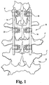
- Fig. 1 depicts a spinal fixation system 10 according to one embodiment of the present invention.
- System 10 is shown attached to a vertebral column 12 comprised of a plurality of vertebra V.
- System 10 generally includes a pair of spinal rods 14, situated on opposite sides of spinal column 12, and a plurality of bone anchors 16, each attached to a portion of vertebra V and affixed along the length of spinal rods 14.
- system 10 can vary in size and configuration such that any number of vertebra V can be held in place relative to one another.
- system 10 can include a single spinal rod 14 attached to one side of spinal column 12.
- system 10 can be used in a variety of applications associated with the spine to address a wide range of spinal pathologies.
- application of system 10 can be limited to the lumbar region of the spine for fixation following a diskectomy.
- system 10 can extend substantially along the entire length of the thoracic and lumbar regions of the spine to correct a deformity such as scoliosis.
- system 10 can provide fixation and stabilization of the cervical spine, such as might occur following a fracture or dislocation. It is of course understood by a person of skill in the art that the configuration of the components of system 10 will vary depending upon the region of the spine to be treated and the type of treatment to be administered.
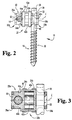
- Figs. 2-4 provide additional details concerning the structure and operation of system 10.
- bone anchor 16 is connected to spinal rod 14 by way of a connecting apparatus 20.
- connecting apparatus 20 includes first and second modules 22a, 22b, first and second compression members 24a, 24b and first and second locking members 26a, 26b.
- Connecting apparatus 20 also defines a longitudinal axis L.
- bone anchor 16 includes a threaded shank 30 that carries threads configured to engage bone.
- the threads are cancellous threads configured to engage vertebral bone, such as vertebra V.
- Bone anchor 16 also includes an upper portion 32.
- Upper portion 32 preferably, but not necessarily, includes a tool receiving recess 36.
- Tool receiving recess 36 can be configured to accept any type of known driving tool.
- tool receiving recess 36 is a hex recess sized to receive the hex end of a driving tool to allow for the threading of bone anchor 16 into a portion of vertebra V.
- Upper portion 32 defines a generally circular outer surface 38.
- outer surface 38 can take on a variety of shapes, such as a square, an ellipse, or a number of other polygonal configurations.
- spinal rod 14 is shown as having a generally circular cross-section, it should be understood that spinal rod 14 can also take on a variety of alternative shapes and configurations.
- First module 22a includes a connector portion 40 and a pair of generally opposing flanges 42a, 42b extending therefrom and aligned generally parallel with longitudinal axis L.
- Connector portion 40 has a substantially circular shape and includes an upper portion 44, an intermediate portion 46 and a lower portion 48.
- Connector portion 40 defines a clamping section 50, at least partially defined by upper portion 44 and intermediate portion 46.
- Clamping section 50 defines an opening 52 extending therethrough and aligned generally perpendicular to longitudinal axis L.
- opening 52 has a first cross-sectional area 52a and a second cross-sectional area 52b, as shown most clearly in Fig. 6.
- first cross-sectional area 52a has a diameter that is substantially equal to either the diameter of spinal rod 14 or upper portion 32 of bone anchor 16.
- Second cross-sectional area 52b has a diameter that is somewhat larger than the diameter of first cross-sectional area 52a, the advantage of which will be discussed later. It should be understood, however, that opening 52 can be configured to define a single, uniform cross-sectional area.
- Clamping section 50 also defines a slit 56 intersecting opening 52.
- Slit 56 extends through upper portion 44 and through a portion of intermediate portion 46.
- slit 56 extends across the entire width of intermediate portion 46 and is aligned generally along longitudinal axis L. Opening 52 and slit 56 thus cooperate to define a C-shaped recess bounded by a pair of generally opposing sidewalls 58a, 58b. It should be understood that opening 52 and slit 56 may define alternatively shaped recesses as well. For example, a U-shaped recess is also contemplated.
- Upper portion 44 has a diameter D 1 .
- the diameter of intermediate portion 46 is greater than diameter D 1 , thus defining an annular shoulder 60 extending continuously about connector portion 40.
- Lower portion 48 has a diameter D 2 that is slightly greater than the diameter of intermediate portion 46, thus defining annular shoulder 62 extending continuously about connector portion 40.
- Annular shoulder 62 is preferably inwardly rounded to define a circular fillet. However, it should be understood that annular shoulder 62 can take on other configurations, such as an angled transition between upper portion 46 and lower portion 48.
- Opposing flanges 42a, 42b generally define a partial cylinder and are disposed generally about longitudinal axis L.
- Flanges 42a, 42b are positioned on opposite sides of connector portion 40 and define an inner diameter D 3 between inner surface 63a of flange 42a and inner surface 63b of flange 42b.
- Flanges 42a, 42b also define an outer diameter D 4 between outer surface 65a of flange 42a and outer surface 65b of flange 42b.
- Inner diameter D 3 is substantially equal to diameter D 2 of lower portion 48.
- Flanges 42a, 42b preferably, but not necessarily, define an inwardly extending lip 64a, 64b.
- Lips 64a, 64b have a partially circular shape, thus defining a circular round which generally corresponds to the circular fillet defined by annular shoulder 62. It should be understood that lips 64a, 64b can also take on other configurations, such as having an angled surface which generally corresponds to an angled transition between upper portion 46 and lower portion 48.
- the ends of flanges 42a, 42b which are positioned adjacent connector portion 40 preferably define a rounded end portion 66 to eliminate sharp edges which may be detrimental during the installation of system 10. As shown in Fig. 7, each of flanges 42a, 42b extends across an angle ⁇ 1 and are separated from one another by an angle ⁇ 2 . In one specific embodiment, angle ⁇ 1 is about 60° and angle ⁇ 2 is about 120°. However, it should be understood that these angles are exemplary and are not intended to limit the scope of protection in any manner.
- first module 22a is illustrated in Figs. 5-7 as having a pair of generally opposing flanges 42a, 42b, in another embodiment of connecting apparatus 20, first module 22a and second module 22b can each have a single flange extending therefrom.
- one of modules 22a, 22b can include a pair of flanges 42a, 42b, while the other of the modules includes either a single flange or no flanges.
- flanges 42a, 42b are attached to connector portion 40, for example, by welding.
- flanges 42a, 42b may also be formed as an integral part of connector portion 40.
- first and second compression members 24a, 24b are disposed about a portion of first and second modules 22a, 22b. More specifically, compression members 24a, 24b are disposed along longitudinal axis L and about a portion of flanges 42a, 42b of modules 22a, 22b. In one feature of the present invention, each of compression members 24a, 24b has a substantially similar configuration. However, it is also contemplated that compression members 24a, 24b may take on different configurations depending on the particular application. Additionally, although the specific embodiment of connecting apparatus 20 is shown to include two compression members 24a, 24b, it should be understood that connecting apparatus 20 need possess only a single compression member.
- Compression members 24a, 24b are at least partially formed of a shape-memory matezial such as, for example, Nitinol®, a biocompatible shape-memory metal alloy of nickel and titanium. It is well known in the art that articles made of such shape-memory materials are pliable and can typically be readily reshaped at temperatures below their transformation temperature range. Such articles can be trained to have a pre-programmed shape which the article will change into when the material reaches a temperature above its transformation temperature range. Thus, after being deformed from its original state, the article will attempt to return to its pre-programmed shape when heated up to a temperature above its transformation temperature range. In so doing, the article converts heat energy into mechanical work.
- a shape-memory matezial such as, for example, Nitinol®, a biocompatible shape-memory metal alloy of nickel and titanium.
- shape-memory materials including shape-memory metal alloys (e.g., titanium based alloys and iron based alloys) and shape-memory polymers, which have a wide range of possible transformation temperature ranges. Selection of an appropriate shape-memory material will depend, in large part, on the required material properties for the particular application and the working environment of the device.
- Nitinol® is well suited for the particular application of the present invention because it provides a transformation temperature range between room temperature and normal human body temperature.
- Nitinol® has a very low corrosion rate, which provides an advantage when used within the human body.
- implant studies in animals have shown minimal elevations of nickel in the tissues in contact with the Nitinol® material.
- other medical-grade shape-memory materials could alternatively be used in place of Nitinol®.
- compression members 24a, 24b are generally ring-shaped and define an inner diameter D 5 . It should be understood that while compression members 24a, 24b are depicted as circular rings, other shapes and configurations are also contemplated as would occur to one of ordinary skill in the art. When the shape-memory material is in its martensitic or room temperature state, inner diameter D 5 is slightly greater than outer diameter D 4 of flanges 42a, 42b.
- each of compression members 24a, 24b includes an inner surface 70 that generally corresponds to outer surfaces 65a, 65b of flanges 42a, 42b, such that compression members 24a, 24b can be slidably received over flanges 42a, 42b of first and second modules 22a, 22b when the shape-memory material is at a temperature below its transformation temperature range.
- first and second locking members 26a, 26b are disposed about a portion of first and second modules 22a, 22b. More specifically, locking members 26a, 26b are disposed along longitudinal axis L and about upper portion 44 of connector portion 40. In one feature of the present invention, each of locking members 26a, 26b has a substantially similar configuration. However, it is also contemplated that locking members 26a, 26b may take on different configurations depending on the particular application. Locking members 26a, 26b are at least partially formed of a shape-memory material such as, for example, Nitinol®.
- locking members 26a, 26b are generally ring-shaped and define an inner diameter D 6 . It should be understood that while locking members 26a, 26b are depicted as circular rings, other shapes and configurations are also contemplated as would occur to one of ordinary skill in the art. When the shape-memory material is in its martensitic or room temperature state, inner diameter D 6 is slightly greater than the outer diameter D 1 of upper portion 44 of connector portion 40.
- each of locking members 26a, 26b includes an inner surface 80 that generally corresponds to the outer surface of upper portion 44, such that locking members 26a, 26b can be slidably received over upper portion 44 of first and second modules 22a, 22b when the shape-memory material is at a temperature below its transformation temperature range.
- connecting apparatus 20 is assembled by positioning flanges 42a, 42b of first module 22a adjacent to and overlapping connector portion 40 of second module 22b, and correspondingly positioning flanges 42a, 42b of second module 22b adjacent to and overlapping connector portion 40 of first module 22a.
- connector portion 40 of second module 22b is telescopically disposed between flanges 42a, 42b of first module 22a
- connector portion 40 of first module 22a is telescopically disposed between flanges 42a, 42b of second module 22b.
- first module 22a and second module 22b are allowed to translate in a telescopic relationship relative to each other generally along longitudinal axis L.
- first module 22a is advanced toward second module 22b until inwardly extending lips 64a, 64b of first module 22a are positioned beyond lower portion 48 of second module 22b, and lips 64a, 64b of second module 22b are correspondingly positioned beyond lower portion 48 of first module 22a. Because the distance between lips 64a and 64b is slightly less than the diameter of lower portion 48, flanges 42a, 42b are outwardly splayed apart while lips 64a, 64b are slid across lower portion 48.
- lips 64a, 64b When lips 64a, 64b are positioned beyond lower portion 48 and adjacent annular shoulder 62, flanges 42a, 42b are allowed to snap back into their unsplayed configuration. Thus, lips 64a, 64b cooperate with annular shoulder 62 to provisionally maintain first and second modules 22a, 22b in sliding engagement.
- flanges 42a, 42b of first and second modules 22a, 22b each respectively include lips 64a, 64b.
- lips 64a, 64b are not necessarily required to be included on both pairs of flanges in order to provisionally maintain modules 22a, 22b in sliding engagement.
- lips 64a, 64b could be included only on flanges 42a, 42b of second module 22b.
- each of flanges 42a, 42b do not necessarily have to include an inwardly extending lip.
- flange 42a could include lip 64a, but flange 42b need not necessarily include lip 64b.
- connecting apparatus 20 illustrates each of first and second modules 22a, 22b as including annular shoulder 62
- annular shoulder 62 is not necessarily required to be included on both modules 22a and 22b.
- annular shoulder 62 need not necessarily be defined continuously about connector portion 40.
- annular shoulder 62 could be defined about only a portion of connector portion 40, or could be defined about generally opposing portions of connector portion 40 between flanges 42a, 42b.
- connecting apparatus 20 In addition to allowing modules 22a, 22b to translate in a telescopic relationship along longitudinal axis L, connecting apparatus 20 also allows modules 22a and 22b to rotate relative to each other generally about axis L. As most clearly illustrated in Figs. 2-4, flanges 42a, 42b of first module 22a are positioned between flanges 42a, 42b of second module 22b. Thus, flanges 42a, 42b of module 22a and flanges 42a, 42b of module 22b are allowed to freely rotate between one another about axis L. The degree of allowable relative rotation between modules 22a and 22b is dictated by angle ⁇ 1 and angle ⁇ 2 , as illustrated in Fig. 7.
- the degree of allowable relative rotation between modules 22a and 22b is equal to ⁇ 2 - ⁇ 1 .
- angle ⁇ 1 is about 60° and angle ⁇ 2 is about 120°.
- the amount of allowable relative rotation between modules 22a and 22b is about 60°.
- compression members 24a, 24b are shown positioned about flanges 42a, 42b of first and second modules 22a, 22b.
- Compression members 24a, 24b have a first configuration in which their effective inner diameter D 5 is slightly larger than the effective outer diameter D 4 of flanges 42a, 42b when the shape-memory material within compression members 24a, 24b is in its martensitic state (i.e., at a temperature below the transformation temperature range). Ideally, the shape-memory material will remain in its martensitic state at room temperature or somewhat below room temperature.
- compression members 24a, 24b are maintained in their first configuration, their axial positions along flanges 42a, 42b can be adjusted and first and second modules 22a, 22b are correspondingly allowed to telescopically translate and rotate relative to one another.
- Bone anchor 16 can then be engaged to a portion of vertebra V by placing a driving tool (not shown) into tool receiving recess 36 and driving threaded shank 30 into vertebral bone.
- a driving tool (not shown) into tool receiving recess 36 and driving threaded shank 30 into vertebral bone.
- bone anchor 16 is driven into vertebra V to a recommended depth for adequate fixation, but preferably not so deep that connecting apparatus 20 will contact or press against vertebral bone when attached to bone anchor 16. It should be understood that bone anchor 16 can alternatively be driven into a portion of vertebra V prior to upper portion 32 being received within opening 52.
- spinal rod 14 and bone anchor 16 can respectively be received within opening 52 of first and second modules 22a and 22b prior to the assembly of connecting apparatus 20.
- first and second modules 22a and 22b can be assembled after insertion of spinal rod 14 and upper portion 32 of bone anchor 16 within openings 52.
- spinal rod 14 can be received within opening 52 of either first module 22a or second module 22b. Bone anchor 16 can then be received within the other of openings 52.
- Locking members 26a and 26b are positioned about upper portion 44 of first and second modules 24a, 24b and adjacent annular shoulder 60.
- Locking members 26a, 26b have a first configuration in which their effective inner diameter D 6 is slightly larger than the effective outer diameter D 1 of upper portion 44 when the shape-memory material within locking members 26a, 26b is in its martensitic state. Ideally, the shape-memory material will remain in its martensitic state at room temperature or somewhat below room temperature.
- Spinal rod 14 and bone anchor 16 are correspondingly allowed to slidably translate within opening 52 relative to clamping section 50.
- connecting apparatus 20 is allowed to slide along the length of spinal rod 14 and pivot about spinal rod 14.
- connecting apparatus 20 is allowed to slide along the length of upper portion 32 of bone anchor 16 and pivot about upper portion 32.
- first module 22a is positioned at a desired axial and rotational position relative to second module 22b
- compression members 24a, 24b are heated up.
- the temperature of compression members 24a, 24b is increased beyond the transformation temperature range of the shape-memory material, the shape-memory material shifts from its martensitic state to its austenitic state.
- compression members 24a, 24b are reformed into a second configuration in which their inner diameter D 5 is reduced.
- compression members 24a, 24b will contract about flange 42a, 42b of first and second modules 22a and 22b.
- each pair of flanges 42a, 42b will correspondingly compress tightly against connector portion 40, and more specifically lower portion 48.
- the super elastic properties of the shape-memory material enables significant recoverable strains, and therefore compression forces, to be developed by compression members 24a, 24b. These forces are transmitted to flanges 42a, 42b, which in turn tightly engage lower portion 48 of connector portion 40, thereby limiting movement of first module 22a relative to second modules 22b.
- first module 22a and second module 22b will no longer be allowed to freely translate along axis L and freely rotate about axis L relative to one another.
- the body temperature of the patient when connecting apparatus 20, and more specifically compression members 24a, 24b, are placed within a patient, the body temperature of the patient will increase the temperature of the shape-memory material and cause it to move from its martensitic state to its austenitic state.
- the temperature of the shape-memory material may be increased above its transformation temperature range by running electric current through compression members 24a, 24b and increasing their temperature through resistance heating.
- the temperature of compression members 24a, 24b may be increased by way of magnetic induction, the application of which would be apparent to one of ordinary skill in the art.
- locking member 25a is heated up.
- locking member 26b is heated up.
- locking members 26a and 26b are heated up substantially concurrently.
- locking members 26a and 26b are heated up substantially concurrently with compression members 24a, 24b.
- locking members 26a, 26b preferably, but not necessarily, are made of a shape-memory material having the same transformation temperature range as that of compression members 24a, 24b.
- locking members 26a, 26b As the temperature of locking members 26a, 26b is increased beyond the transformation temperature range of the shape-memory material, the shape-memory material shifts from its martensitic state to its austenitic state. In the austenitic state, locking members 26a, 26b are reformed into a second configuration in which their inner diameter D 6 is reduced to a preprogrammed size slightly smaller than outer diameter D 1 of upper portion 44. Thus, when locking members 26a, 26b are reformed into their second configuration at a temperature above the transformation temperature range of the shape-memory material, locking members 26a, 26b will contract about upper portion 44 of first and second modules 22a, 22b, respectively.
- the body temperature of the patient when connecting apparatus 20, and more specifically locking members 26a, 26b, are placed within a patient, the body temperature of the patient will increase the temperature of the shape-memory material and cause it to move from its martensitic state to its austenitic state.
- Clamping section 50 of first module 22a is configured to allow spinal rod 14 to bend within opening 52.
- second cross-sectional area 52b has a diameter somewhat larger than first cross-sectional area 52a.
- first cross-sectional area 52a has a diameter that is substantially equal to the diameter of spinal rod 14. If spinal rod 14 is required to be bent to more closely conform to the curvature of the spinal column, second cross-sectional area 52b provides sufficient space for spinal rod 14 to deform and bend within opening 52. It should be understood that second cross-sectional area 52b is not necessarily required to be included in clamping section 50 of second module 22b unless upper portion 32 of bone anchor 16 is also required to bend within opening 52.
- clamping section 50 of first and second modules 22a, 22b slit 56 is widened to approximately the width of first cross-sectional area 52a of opening 52.
- clamping section 50 may define an open, U-shaped recess.
- spinal rod 14 and upper portion 32 of bone anchor 16 could be top-loaded into clamping section 50 of modules 22a, 22b.
- Side walls 58a, 58b would thus form a pair of gripping prongs which, when heated to a temperature above the transformation temperature range of the shape-memory material, would contract about a portion of spinal rod 14 or upper portion 32 of bone anchor 16. Relative movement between connecting apparatus 20 and spinal rod 14 and bone anchor 16 would thus be limited.
- connector portion 40 of first and second modules 22a, 22b could define a circular groove positioned generally about longitudinal axis L and sized to receive flanges 42a, 42b of the opposing module therein.
- compression members 24a, 24b could alternatively be positioned between flanges 42a, 42b of modules 22a, 22b.
- compression members 24a, 24b would have a first configuration in which their outer diameter would be sized slightly smaller than inner diameter D 3 of flanges 42a, 42b when the shape-memory material is in its martensitic state.
- first and second modules 22a, 22b would be allowed to telescopically translate and rotate relative to one another.
- first module 22a is positioned at a desired axial and rotational position relative to second module 22b
- compression members 24a, 24b may be heated up.
- the shape-memory matezial will shift from its martensitic state to its austenitic state.
- compression members 24a, 24b will be reformed into a second configuration in which their outer diameter is increased to a preprogrammed size slightly larger than inner diameter D 3 of flanges 42a, 42b.
- connecting apparatus 20 could also be configured to provisionally maintain first and second modules 22a, 22b in a telescopic relationship, similar to the telescopic relationship described above.
- lips 64a, 64b must correspondingly be repositioned to extend outwardly from flanges 42a, 42b.
- annular shoulder 62 must be defined by the outer surface of the circular groove defined in connector portion 40.
- first module 22a first and second modules 22a, 22b may have substantially identical configurations or may have different configurations.
- first module 22a defines a longitudinal axis L about which it is generally symmetrical.
- Connector portion 40 has an overall height of about 10mm measured from the top surface of upper portion 44 to the bottom surface of lower portion 48. More specifically, upper portion 44 has a height of about 2.023mm, intermediate portion 46 has a height of about 5.477mm and lower portion 48 has a height of about 2.5mm. Diameter D 1 of upper portion 44 is preferably about 9mm and diameter D 2 of lower portion 48 is preferably about 14mm. Intermediate portion 46 has a diameter slightly less than diameter D 2 of lower portion 48, and is preferably about 13mm. As described above, flanges 42a, 42b extend across an angle ⁇ 1 .
- angle ⁇ 1 is about 60°.
- flanges 42a, 42b are separated from one another by angle ⁇ 2 .
- angle ⁇ 2 is about 120°.
- Inner diameter D 3 is substantially equal to outer diameter D 2 of lower portion 48. More specifically, diameter D 3 is preferably about 14mm.
- Outer diameter D 4 is preferably about 16mm. Therefore, the thickness of each of flanges 42a, 42b is approximately 1mm.
- Inwardly extending lips 64a, 64b are preferably rounded to a radius of 0.5mm.
- annular shoulder 62 preferably defines a rounded fillet of about 0.5mm.
- the overall length of module 22a as measured between the upper surface of upper portion 44 and the lower end of flanges 42a, 42b, is about 20mm.
- the center line of opening 52 including first cross-sectional area 52a and second cross sectional area 52b, is located about 4.74mm from the bottom surface of lower portion 48.
- First cross-sectional area 52a preferably has a diameter of about 6.477mm and second cross-sectional area 52b preferably has a diameter of about 6.985mm.
- Second cross-sectional area 52b is generally centered along axis L and has an overall length of about 8mm.
- compression members 24a, 24b have an inner diameter D 5 when at a temperature below the transformation temperature range (i.e., when the shape-memory material is in its martensitic state). In this state, inner diameter D 5 is slightly greater than outer diameter D 4 of flanges 42a, 42b, and is preferably about 16.5mm.
- inner diameter D 5 is reduced so that inner surface 70 may bear against flanges 42a, 42b and tightly compress flanges 42a, 42b against connector portion 40 of the opposing module.
- the outer diameter of compression members 24a, 24b is preferably about 18mm.
- the thickness of compression members 24a, 24b is preferably about 3mm.
- Locking members 26a, 26b have an inner diameter D 6 when at a temperature below the transformation temperature range. In this state, inner diameter D 6 is slightly greater than outer diameter D 1 of upper portion 44 of connector portion 40, and is preferably about 9.5mm. When locking members 26a, 26b are increased to a temperature above the transformation temperature range, inner diameter D 6 is reduced so that inner surface 80 may bear against upper portion 44 and tightly compress sidewalls 58a, 58b against the corresponding spinal rod 14 or bone anchor 16.
- the outer diameter of locking members 26a, 26b is preferably equal to or slightly less than the diameter of intermediate portion 46, and is preferably about 13mm.
- the thickness of locking members 26a, 26b is preferably slightly less than or equal to the height of upper portion 44 and is preferably about 2mm. As previously mentioned, variations in these design parameters which would occur to a person of ordinary skill in the art are contemplated as within the scope of the invention and are therefore not intended to limit the scope of protection.
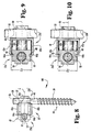
- system 100 is provided as shown in Figs. 8-10.
- bone anchor 16 is connected to spinal rod 14 by way of connecting apparatus 20'.
- Connecting apparatus 20' includes first and second modules 22a, 22b'.
- connecting apparatus 20' does not include compression members 24a, 24b or locking members 26a, 26b.
- First and second modules 22a' and 22b' are configured dimensionally identical to first and second modules 22a, 22b. Therefore, reference will be made to like structural elements previously labeled in Figs. 5-7 and discussed in detail above. It should be understood, however, that first and second modules 22a', 22b'may take on configurations different from those of modules 22a, 22b.
- First and second modules 22a', 22b' are shown assembled substantially identical to first and second modules 22a, 22b, as illustrated in Fig. 2 and discussed in detail above.
- connecting apparatus 20' is assembled by positioning flanges 42a, 42b of first module 22a' adjacent to and overlapping connector portion 40 of second module 22b', and correspondingly positioning flanges 42a, 42b of second module 22b' adjacent to and overlapping connector portion 40 of first module 22a'.
- modules 22a' and 22b' are allowed to translate in a telescopic relationship relative to one another generally along longitudinal axis L, and are provisionally maintained in this telescopic relationship by way of cooperation between lips 64a, 64b and annular shoulder 62.
- modules 22a' and 22b' are allowed to rotate relative to each other generally about axis L.
- a portion of each pair of flanges 42a, 42b is formed of a shape-memory material. More specifically, at least one of flanges 42a, 42b is at least partially formed of a shape-memory material such as, for example, Nitinol®.
- FIG. 9 therein is illustrated a first operational configuration of connecting apparatus 20'.
- Flanges 42a, 42b of first and second modules 24a', 24b' have a first configuration in which inner diameter D 3 is substantially equal to outer diameter D 2 of lower portion 48 when the shape-memory material is in its martensitic state (i.e., at a temperature below the transformation temperature range).
- Fig. 9 depicts an exaggerated degree of clearance between flanges 42a, 42b and lower portion 48.
- the shape-memory material will remain in its martensitic state at room temperature or somewhat below room temperature.
- first and second modules 22a' and 22b' are allowed to telescopically translate along axis L and rotate about axis L relative to one another.
- FIG. 10 there is illustrated a second operational configuration of connecting apparatus 20'.
- first and second modules 22a', 22b' are positioned at a desired axial and rotational position relative to one another, each pair of flanges 42a, 42b is heated up.
- the shape-memory material shifts from its martensitic state to its austenitic state.
- each pair of flanges 42a, 42b is reformed into a second configuration in which inner diameter D 3 is reduced.
- flanges 42a, 42b when flanges 42a, 42b is reformed into their second configuration at a temperature above the transformation temperature range of the shape-memory material, flanges 42a, 42b will contract about lower portion 48 of the opposing module. In this second configuration, flanges 42a, 42b are compressed tightly against lower portion 48 of connector portion 40, thereby limiting movement of first module 22a' relative to second module 22b'. Accordingly, first and second modules 22a', 22b' will no longer be allowed to freely translate along axis L and freely rotate about axis L relative to one another.
- connecting apparatus 20' can have an alternative embodiment in which connector portion 40 of first and second modules 22a', 22b' defines a circular groove positioned generally about axis L and sized to receive flanges 42a, 42b of the opposing module therein.
- Flanges 42a, 42b of first and second modules 24a', 24b' have a first configuration in which outer diameter D 4 would be sized slightly smaller than the outer diameter of the circular groove defined in connector portion 40 of the opposing module when the shape-memory material is in its martensitic state. While in this first configuration, first and second modules 22a', 22b' would be allowed to telescopically translate and rotate relative to one another.
- each pair of flanges 42a, 42b would be reformed into a second configuration in which outer diameter D 4 is increased.
- first module 22a' and second module 22b' will no longer be allowed to freely translate along axis L and freely rotate about axis L relative to one another.
- lips 64a, 64b must be repositioned to extend outwardly from flanges 42a, 42b and annular shoulder 62 must be defined by the outer surface of the circular groove defined in connector portion 40.
- each of clamping sections 50 is at least partially formed of a shape-memory material. More specifically, at least one of sidewalls 58a, 58b is at least partially formed of a shape-memory material such as, for example Nitinol®.
- the first operational configuration of connecting apparatus 20' shows clamping section 50 of first and second modules 22a', 22b' as having a first configuration.
- This first configuration illustrates opening 52 as having a diameter, which is slightly greater than the outer diameter of spinal rod 14 and upper portion 32 of bone anchor 16 when the shape-memory material is in its martensitic state.
- first module 22a' is allowed to slide along the length and pivot about spinal rod 14.
- second module 22b' is allowed to slide along the length and pivot about upper portion 32 of bone anchor 16.
- clamping section 50 of modules 22a', 22b' is heated up.
- the temperature of clamping section 50 is increased beyond the transformation temperature range of the shape-memory material, the shape-memory material shifts from its martensitic state to its austenitic state.
- clamping section 50 is reformed into a second configuration in which the diameter of opening 52, and more specifically cross-sectional area 52a, is reduced.
- first and second modules 22a', 22b' will no longer be allowed to freely slide along the length or pivot about spinal rod 14 or upper portion 32 of bone anchor 16.
- clamping section 50 of first and second modules 22a', 22b' slit 56 is widened to approximately the width of first cross-sectional area 52a of opening 52.
- clamping section 50 would define an open, U-shaped recess.
- spinal rod 14 and upper portion 32 of bone anchor 16 could be top-loaded into clamping section 50 of modules 22a', 22b'.
- Side walls 58a, 58b would thus form a pair of gripping prongs which, when heated to a temperature above the transformation temperature range of the shape-memory material, would contract about a portion of spinal rod 14 or upper portion 32 of bone anchor 16. Relative movement between connecting apparatus 20' and spinal rod 14 and bone anchor 16 would thus be limited.
- connecting apparatus 20 and connecting apparatus 20' can alternatively be used to connect other members having various configurations.
- connecting apparatus 20, 20' could be used to connect spinal rod 14 to a transverse rod, which in turn may be connected to another spinal rod 14 positioned on the opposite side of spinal column 12.
- connecting apparatus 20, 20' could be used to connect a spinal rod to a bone anchor, such as bone anchor 16, other bone engaging fasteners are also contemplated.
- connecting apparatus 20, 20' could be used to connect a spinal rod to a vertebral hook or bone bolt.
- components of systems 10,100 can be correspondingly sized according to the portion of a spine within which the particular assembly is to be used, For instance, treatment of the lumbar region of the spine may require components which are sized somewhat larger than components used to treat the thoracic and cervical regions of the spine.
Abstract
Description
Claims (28)
- A connecting apparatus, comprising:a first module (22a) having a first connector portion (40) and a first flange (42a) extending therefrom, said first connector portion (40) being adapted for connection to a first member,a second module (22b) having a second connector portion (40) and a second flange (42a) extending therefrom, said second connector portion (40) being adapted for connection to a second member;said first flange (42a) being disposed adjacent to and overlapping a portion of said second connector portion (40), said second flange (42a) being disposed adjacent to and overlapping a portion of said first connector portion (40);a first compression member (24a) at least partially formed of a shape-memory material, said first compression member (24a) being disposed adjacent to said first and second flanges (42a); andsaid first compression member (24a) having a first configuration at one temperature and a second configuration at a different temperature, said first configuration allowing movement of said first module (22a) relative to said second module (22b), said second configuration limiting movement of said first module (22a) relative to said second module (22b).
- The apparatus of claim 1, wherein said first compression member (24a) is disposed about at least a portion of both said first and second flanges (42a) and engages said first and second flanges (42a) and compresses said first and second flanges (42a) respectively against said second and first connector portions (40) when said first compression member (24a) is in said second configuration.
- The apparatus of claim 1, wherein said first module (22a) has a third flange (42b) extending therefrom at a location generally opposite said first flange (42a), said first and third flanges (42a, 42b) defining a first pair of flanges, said second module (22b) has a fourth flange (42b) extending therefrom at a location generally opposite said second flange (42a), said second and fourth flanges (42a, 42b) defining a second pair of flanges.
- The apparatus of claim 3, wherein said first connector portion (40) is telescopically disposed between said flanges (42a, 42b) of said second pair, said second connector portion (40) being telescopically disposed between said flanges (42a, 42b) of said first pair, and wherein said first and second modules (22a, 22b) are allowed to translate in a telescopic relationship relative to each other when said first compression member (24a) is in said first configuration.
- The apparatus of claim 4, wherein at least one flange (42a) of said first and second pairs of flanges defines an inwardly extending lip (64a), and wherein at least one of said first and second connector portions (40) disposed between the flanges (42a, 42b) of said at least one of said first and second pairs of flanges has an outer surface defining a shoulder (62), said lip (64a) cooperating with said shoulder (62) to provisionally maintain said first and second modules (22a, 22b) in said telescopic relationship.
- The apparatus of claim 5, wherein both flanges (42a, 42b) of said at least one of said first and second pairs of flanges define said lip (64a), and wherein said shoulder (62) is defined continuously about said outer surface.
- The apparatus of claim 3, wherein the flanges (42a, 42b) of said first pair are disposed between the flanges (42a, 42b) of said second pair, and wherein said first and second modules (22a, 22b) are allowed to rotate relative to each other when said first compression member (24a) is in said first configuration.
- The apparatus of claim 1, wherein said first compression member (24a) is a ring defining an inner annular surface (70), said first and second flanges (42a, 42b) each defining a rounded outer surface (65a, 65b) generally corresponding to said inner annular surface (70).
- The apparatus of claim 1, further comprising a second compression member (24b) at least partially formed of said shape-memory material, said second compression member (24b) being disposed about at least a portion of both said first and second flanges (42a).
- The apparatus of claim 1, further comprising a locking member (26a) at least partially formed of a shape-memory material, and wherein at least one of said first and second connector portions (40) includes a clamping section (50) associated with one of said first and second members, said locking member (26a) being disposed about at least a portion of said clamping section (50), said locking member (26a) allowing movement of said clamping section (50) relative to said one of said first and second members when at one temperature of said locking member (26a), said locking member (26a) contracting about said clamping section (50) when at a different temperature of said locking member (26a) to limit movement of said clamping section (50) relative to said one of said first and second members.
- The apparatus of claim 10, wherein said locking member (26a) is a ring defining an inner annular surface (80), said clamping section (50) defining a rounded outer surface generally corresponding to said inner annular surface (80).
- The apparatus of claim 10, wherein said shape-memory material of the first compression member (24a) and said shape-memory material of the locking member (26a) have the same composition.
- The apparatus of claim 10, wherein said clamping section (50) defines an opening (52) extending therethrough.
- The apparatus of claim 13, wherein said clamping section (50) further defines a slit (56) intersecting said opening (52).
- The apparatus of claim 13, wherein said opening (52) is sized to receive a rod (14), said clamping section (50) configured to allow said rod (14) to bend within said opening (52).
- The apparatus of claim 13, wherein said first member comprises a first part of a spinal column and said second member comprises a second part of said spinal column, and wherein said connecting apparatus is part of a spinal fixation system, said first connector portion (40) including a first of said clamping section (50), said opening (52) in said first clamping section (50) being sized to receive a spinal rod (14), said spinal rod (14) being configured to connect to said first part of said spinal column, said second connector portion (40) including a second of said clamping section (50), said opening (52) in said second clamping section (50) being sized to receive a bone anchor (16), said bone anchor (16) being configured to engage said second part of said spinal column.
- The apparatus of claim 1, wherein said first member is a spinal rod (14) and said second member is a bone anchor (16).
- A connecting apparatus, comprising:a first module (22a') having a first connector portion (40) and a first pair of flanges (42a, 42b) extending therefrom, said first connector portion (40) being adapted for connection to a first member;a second module (22b') having a second connector portion (40) and a second pair of flanges (42a, 42b) extending therefrom, said second connector portion (40) being adapted for connection to a second member;at least one flange of said first pair of flanges (42a, 42b) being at least partially formed of a shape-memory material, said first pair of flanges (42a, 42b) being disposed adjacent to and overlapping a portion of said second connector portion (40);at least one flange of said second pair of flanges (42a, 42b) at least partially formed of a shape-memory material, said second pair of flanges (42a, 42b) being disposed adjacent to and overlapping a portion of said first connector portion (40); andsaid first and second pairs of flanges having a first configuration at one temperature and a second configuration at a different temperature, said first configuration allowing movement of said first module (22a') relative to said second module (22b'), said second configuration limiting movement of said first module (22a') relative to said second module (22b').
- The apparatus of claim 18, wherein said first and second pairs of flanges (42a, 42b) compress respectively against said second and first connector portions (40) when said first and second pairs of flanges (42a, 42b) are in said second configuration.
- The apparatus of claim 18, wherein at least one flange (42a) of said first and second pairs of flanges defines an inwardly extending lip (64a), and wherein at least one of said first and second connector portions (40) disposed between the flanges (42a, 42b) of said at least one of said first and second pairs of flanges has an outer surface defining a shoulder (62), said lip (64a) cooperating with said shoulder (62) to provisionally maintain said first and second modules (22a', 22b') in a telescopic relationship.
- The apparatus of claim 20, wherein both flanges (42a, 42b) of said at least one of said first and second pairs of flanges define said lip (64a, 64b), and wherein said shoulder (62) is defined continuously about said outer surface.
- The apparatus of claim 18, wherein the flanges (42a, 42b) of said first pair are disposed between the flanges (42a, 42b) of said second pair, and wherein said first and second modules (22a', 22b') are allowed to rotate relative to each other when said first and second pairs of flanges (42a, 42b) are in said first configuration.
- The apparatus of claim 18, wherein at least one of said first and second connector portions (40) includes a clamping section (50) associated with one of said first and second members, said clamping section (50) at least partially formed of a shape-memory material, said clamping section (50) allowing movement of said clamping section (50) relative to said one of said first and second members when at one temperature, said clamping section (50) inwardly contracting when at a different temperature to limit movement of said clamping section (50) relative to said one of said first and second members.
- The apparatus of claim 23, wherein said shape-memory material of the flanges (42a, 42b) and said shape-memory material of the clamping section (50) have the same composition.
- The apparatus of claim 23, wherein said clamping section (50) defines an opening (52) extending therethrough.
- The apparatus of claim 25, wherein said clamping section (50) includes a pair of generally opposing side walls (58a, 58b), said side walls (58a, 58b) defining said opening (52), said opening (52) being a C-shaped recess.
- The apparatus of claim 25, wherein said first member comprises a first part of a spinal column and said second member comprises a second part of said spinal column, and wherein said connecting apparatus is part of a spinal fixation system, said first connector portion (40) including a first of said clamping section (50), said opening (52) in said first clamping section (50) being sized to receive a spinal rod (14), said spinal rod (14) being configured to connect to said first part of said spinal column, said second connector portion (40) including a second of said clamping section (50), said opening (52) in said second clamping (50) section being sized to receive a bone anchor (16), said bone anchor (16) being configured to engage said second part of said spinal column.
- The apparatus of claim 18, wherein said first member is a spinal rod (14) and said second member is a bone anchor (16).
Applications Claiming Priority (5)
| Application Number | Priority Date | Filing Date | Title |
|---|---|---|---|
| US13091199P | 1999-04-23 | 1999-04-23 | |
| US130911P | 1999-04-23 | ||
| US09/408,364 US6210413B1 (en) | 1999-04-23 | 1999-09-29 | Connecting apparatus using shape-memory technology |
| US408364 | 1999-09-29 | ||
| PCT/US2000/007662 WO2000064362A1 (en) | 1999-04-23 | 2000-03-22 | Connecting apparatus using shape-memory technology |
Publications (2)
| Publication Number | Publication Date |
|---|---|
| EP1171048A1 EP1171048A1 (en) | 2002-01-16 |
| EP1171048B1 true EP1171048B1 (en) | 2003-06-11 |
Family
ID=26828964
Family Applications (1)
| Application Number | Title | Priority Date | Filing Date |
|---|---|---|---|
| EP00919547A Expired - Lifetime EP1171048B1 (en) | 1999-04-23 | 2000-03-22 | Connecting apparatus using shape-memory technology |
Country Status (9)
| Country | Link |
|---|---|
| US (1) | US6210413B1 (en) |
| EP (1) | EP1171048B1 (en) |
| JP (1) | JP4349751B2 (en) |
| AT (1) | ATE242615T1 (en) |
| AU (1) | AU762883B2 (en) |
| CA (1) | CA2368250C (en) |
| DE (1) | DE60003302T2 (en) |
| ES (1) | ES2198299T3 (en) |
| WO (1) | WO2000064362A1 (en) |
Families Citing this family (119)
| Publication number | Priority date | Publication date | Assignee | Title |
|---|---|---|---|---|
| US6283967B1 (en) | 1999-12-17 | 2001-09-04 | Synthes (U.S.A.) | Transconnector for coupling spinal rods |
| US6293949B1 (en) | 2000-03-01 | 2001-09-25 | Sdgi Holdings, Inc. | Superelastic spinal stabilization system and method |
| CA2415072C (en) * | 2000-06-30 | 2011-05-31 | Stephen Ritland | Polyaxial connection device and method |
| US7166073B2 (en) * | 2000-09-29 | 2007-01-23 | Stephen Ritland | Method and device for microsurgical intermuscular spinal surgery |
| US6685705B1 (en) * | 2000-10-23 | 2004-02-03 | Sdgi Holdings, Inc. | Six-axis and seven-axis adjustable connector |
| US6520962B1 (en) * | 2000-10-23 | 2003-02-18 | Sdgi Holdings, Inc. | Taper-locked adjustable connector |
| US8021399B2 (en) | 2005-07-19 | 2011-09-20 | Stephen Ritland | Rod extension for extending fusion construct |
| ATE495709T1 (en) * | 2001-09-28 | 2011-02-15 | Stephen Ritland | CONNECTING ROD FOR A POLYAXIAL SYSTEM WITH SCREW OR HOOK |
| WO2003061494A1 (en) * | 2002-01-23 | 2003-07-31 | Ashman Richard B | Variable angle spinal implant connection assembly |
| US6648887B2 (en) * | 2002-01-23 | 2003-11-18 | Richard B. Ashman | Variable angle spinal implant connection assembly |
| EP1545353B1 (en) | 2002-02-20 | 2010-08-11 | Stephen Ritland | Pedicle screw connector apparatus |
| US6966910B2 (en) * | 2002-04-05 | 2005-11-22 | Stephen Ritland | Dynamic fixation device and method of use |
| US20030204268A1 (en) * | 2002-04-25 | 2003-10-30 | Medicinelodge, Inc. | Binary attachment mechanism and method for a modular prosthesis |
| US7182786B2 (en) | 2002-04-25 | 2007-02-27 | Zimmer Technology, Inc. | Modular bone implant, tool, and method |
| US6875239B2 (en) * | 2002-04-25 | 2005-04-05 | Medicinelodge, Inc. | Modular prosthesis for replacing bone and method |
| US7682375B2 (en) | 2002-05-08 | 2010-03-23 | Stephen Ritland | Dynamic fixation device and method of use |
| US6887276B2 (en) * | 2002-12-13 | 2005-05-03 | Medicine Lodge, Inc | Modular implant for joint reconstruction and method of use |
| CA2516791C (en) | 2003-02-25 | 2011-12-13 | Stephen Ritland | Adjustable rod and connector device and method of use |
| WO2004110247A2 (en) * | 2003-05-22 | 2004-12-23 | Stephen Ritland | Intermuscular guide for retractor insertion and method of use |
| US7270665B2 (en) * | 2003-06-11 | 2007-09-18 | Sdgi Holdings, Inc. | Variable offset spinal fixation system |
| US7794476B2 (en) * | 2003-08-08 | 2010-09-14 | Warsaw Orthopedic, Inc. | Implants formed of shape memory polymeric material for spinal fixation |
| US7708764B2 (en) | 2003-11-10 | 2010-05-04 | Simonson Peter M | Method for creating an artificial facet |
| US7083622B2 (en) * | 2003-11-10 | 2006-08-01 | Simonson Peter M | Artificial facet joint and method |
| US20050101953A1 (en) * | 2003-11-10 | 2005-05-12 | Simonson Peter M. | Artificial facet joint and method |
| US7261715B2 (en) * | 2003-11-24 | 2007-08-28 | Sdgi Holdings, Inc. | Grommet assembly |
| US7678137B2 (en) * | 2004-01-13 | 2010-03-16 | Life Spine, Inc. | Pedicle screw constructs for spine fixation systems |
| US7377922B2 (en) * | 2004-04-15 | 2008-05-27 | Warsaw Orthopedic, Inc. | Transfer ring for offset tapered 3D connector |
| US20050245932A1 (en) * | 2004-04-16 | 2005-11-03 | Fanton Gary S | Apparatus and methods for securing tissue to bone |
| US7938847B2 (en) * | 2006-01-04 | 2011-05-10 | Tornier, Inc. | Ring cinch assembly to attach bone to tissue |
| US8021398B2 (en) * | 2004-06-09 | 2011-09-20 | Life Spine, Inc. | Spinal fixation system |
| US7938848B2 (en) * | 2004-06-09 | 2011-05-10 | Life Spine, Inc. | Spinal fixation system |
| US7744635B2 (en) * | 2004-06-09 | 2010-06-29 | Spinal Generations, Llc | Spinal fixation system |
| WO2006016371A2 (en) * | 2004-08-13 | 2006-02-16 | Mazor Surgical Technologies Ltd | Minimally invasive spinal fusion |
| US7722654B2 (en) * | 2004-10-05 | 2010-05-25 | Warsaw Orthopedic, Inc. | Spinal implants with multi-axial anchor assembly and methods |
| US7794477B2 (en) * | 2004-10-05 | 2010-09-14 | Warsaw Orthopedic, Inc. | Spinal implants and methods with extended multi-axial anchor assemblies |
| US7572280B2 (en) * | 2004-10-05 | 2009-08-11 | Warsaw Orthopedic, Inc. | Multi-axial anchor assemblies for spinal implants and methods |
| WO2006058221A2 (en) | 2004-11-24 | 2006-06-01 | Abdou Samy M | Devices and methods for inter-vertebral orthopedic device placement |
| US7862588B2 (en) * | 2005-02-18 | 2011-01-04 | Samy Abdou | Devices and methods for dynamic fixation of skeletal structure |
| WO2006096381A2 (en) * | 2005-03-03 | 2006-09-14 | Accelerated Innovation Llc | Spinal stabilization using bone anchor seat and cross coupling with improved locking feature |
| WO2006108114A2 (en) | 2005-04-01 | 2006-10-12 | The Regents Of The University Of Colorado | A graft fixation device and method |
| US7794481B2 (en) | 2005-04-22 | 2010-09-14 | Warsaw Orthopedic, Inc. | Force limiting coupling assemblies for spinal implants |
| US7695499B2 (en) * | 2005-04-29 | 2010-04-13 | Warsaw Orthopedic, Inc. | System, devices and method for augmenting existing fusion constructs |
| US7850715B2 (en) * | 2005-04-29 | 2010-12-14 | Warsaw Orthopedic Inc. | Orthopedic implant apparatus |
| US8128665B2 (en) * | 2005-04-29 | 2012-03-06 | Warsaw Orthopedic, Inc. | Orthopedic implant apparatus |
| US7625394B2 (en) * | 2005-08-05 | 2009-12-01 | Warsaw Orthopedic, Inc. | Coupling assemblies for spinal implants |
| US7628799B2 (en) * | 2005-08-23 | 2009-12-08 | Aesculap Ag & Co. Kg | Rod to rod connector |
| US7575587B2 (en) * | 2005-12-30 | 2009-08-18 | Warsaw Orthopedic, Inc. | Top-tightening side-locking spinal connector assembly |
| WO2007081986A2 (en) * | 2006-01-10 | 2007-07-19 | Life Spine, Inc. | Pedicle screw constructs and spinal rod attachment assemblies |
| US20070173827A1 (en) * | 2006-01-20 | 2007-07-26 | Sdgi Holdings, Inc. | Adjustable connector for attachment to a rod in a medical application |
| US7585299B2 (en) * | 2006-02-17 | 2009-09-08 | Warsaw Orthopedic, Inc. | Dorsal adjusting spinal connector assembly |
| AU2007227349B2 (en) * | 2006-03-22 | 2013-02-07 | Tornier, Inc. | Bone anchor installer and method of use |
| US7753940B2 (en) * | 2006-04-05 | 2010-07-13 | Warsaw Orthopedic, Inc. | Lateral connector assembly |
| US8172882B2 (en) | 2006-06-14 | 2012-05-08 | Spartek Medical, Inc. | Implant system and method to treat degenerative disorders of the spine |
| US7959564B2 (en) | 2006-07-08 | 2011-06-14 | Stephen Ritland | Pedicle seeker and retractor, and methods of use |
| US8388660B1 (en) | 2006-08-01 | 2013-03-05 | Samy Abdou | Devices and methods for superior fixation of orthopedic devices onto the vertebral column |
| US8444682B2 (en) * | 2006-09-13 | 2013-05-21 | The University Of Hong Kong | Shape memory locking device for orthopedic implants |
| US20080114457A1 (en) * | 2006-11-14 | 2008-05-15 | Warsaw Orthopedic, Inc. | Methods and devices for connecting implants and devices |
| US7744632B2 (en) * | 2006-12-20 | 2010-06-29 | Aesculap Implant Systems, Inc. | Rod to rod connector |
| US7931676B2 (en) * | 2007-01-18 | 2011-04-26 | Warsaw Orthopedic, Inc. | Vertebral stabilizer |
| EP2120753B1 (en) * | 2007-03-05 | 2022-09-28 | Tornier, Inc. | Tack anchor systems |
| CN101730551B (en) * | 2007-04-19 | 2016-01-27 | 史密夫和内修有限公司 | Orientated polymeric devices |
| US8114134B2 (en) | 2007-06-05 | 2012-02-14 | Spartek Medical, Inc. | Spinal prosthesis having a three bar linkage for motion preservation and dynamic stabilization of the spine |
| US8070776B2 (en) | 2007-06-05 | 2011-12-06 | Spartek Medical, Inc. | Deflection rod system for use with a vertebral fusion implant for dynamic stabilization and motion preservation spinal implantation system and method |
| US8109970B2 (en) | 2007-06-05 | 2012-02-07 | Spartek Medical, Inc. | Deflection rod system with a deflection contouring shield for a spine implant and method |
| US8021396B2 (en) | 2007-06-05 | 2011-09-20 | Spartek Medical, Inc. | Configurable dynamic spinal rod and method for dynamic stabilization of the spine |
| US8083772B2 (en) | 2007-06-05 | 2011-12-27 | Spartek Medical, Inc. | Dynamic spinal rod assembly and method for dynamic stabilization of the spine |
| US8105356B2 (en) | 2007-06-05 | 2012-01-31 | Spartek Medical, Inc. | Bone anchor with a curved mounting element for a dynamic stabilization and motion preservation spinal implantation system and method |
| US8092501B2 (en) | 2007-06-05 | 2012-01-10 | Spartek Medical, Inc. | Dynamic spinal rod and method for dynamic stabilization of the spine |
| WO2008151091A1 (en) | 2007-06-05 | 2008-12-11 | Spartek Medical, Inc. | A deflection rod system for a dynamic stabilization and motion preservation spinal implantation system and method |
| US8048115B2 (en) | 2007-06-05 | 2011-11-01 | Spartek Medical, Inc. | Surgical tool and method for implantation of a dynamic bone anchor |
| US20090076549A1 (en) * | 2007-09-17 | 2009-03-19 | Warsaw Orthopedic, Inc. | Orthopedic implant system |
| US8808332B2 (en) * | 2012-12-31 | 2014-08-19 | Globus Medical, Inc. | Method for stabilizing the spine |
| US8337536B2 (en) | 2008-02-26 | 2012-12-25 | Spartek Medical, Inc. | Load-sharing bone anchor having a deflectable post with a compliant ring and method for stabilization of the spine |
| US8267979B2 (en) | 2008-02-26 | 2012-09-18 | Spartek Medical, Inc. | Load-sharing bone anchor having a deflectable post and axial spring and method for dynamic stabilization of the spine |
| US8211155B2 (en) | 2008-02-26 | 2012-07-03 | Spartek Medical, Inc. | Load-sharing bone anchor having a durable compliant member and method for dynamic stabilization of the spine |
| US8057517B2 (en) | 2008-02-26 | 2011-11-15 | Spartek Medical, Inc. | Load-sharing component having a deflectable post and centering spring and method for dynamic stabilization of the spine |
| US8097024B2 (en) | 2008-02-26 | 2012-01-17 | Spartek Medical, Inc. | Load-sharing bone anchor having a deflectable post and method for stabilization of the spine |
| US8083775B2 (en) | 2008-02-26 | 2011-12-27 | Spartek Medical, Inc. | Load-sharing bone anchor having a natural center of rotation and method for dynamic stabilization of the spine |
| US20100030224A1 (en) | 2008-02-26 | 2010-02-04 | Spartek Medical, Inc. | Surgical tool and method for connecting a dynamic bone anchor and dynamic vertical rod |
| US8048125B2 (en) | 2008-02-26 | 2011-11-01 | Spartek Medical, Inc. | Versatile offset polyaxial connector and method for dynamic stabilization of the spine |
| US8333792B2 (en) | 2008-02-26 | 2012-12-18 | Spartek Medical, Inc. | Load-sharing bone anchor having a deflectable post and method for dynamic stabilization of the spine |
| US9060813B1 (en) | 2008-02-29 | 2015-06-23 | Nuvasive, Inc. | Surgical fixation system and related methods |
| US8221473B2 (en) * | 2008-03-13 | 2012-07-17 | Life Spine, Inc. | Spinal rod connector assembly for a vertebral bone screw |
| US8414584B2 (en) | 2008-07-09 | 2013-04-09 | Icon Orthopaedic Concepts, Llc | Ankle arthrodesis nail and outrigger assembly |
| WO2010006195A1 (en) | 2008-07-09 | 2010-01-14 | Amei Technologies, Inc. | Ankle arthrodesis nail and outrigger assembly |
| US8147523B2 (en) * | 2008-09-09 | 2012-04-03 | Warsaw Orthopedic, Inc. | Offset vertebral rod connector |
| US8876869B1 (en) | 2009-06-19 | 2014-11-04 | Nuvasive, Inc. | Polyaxial bone screw assembly |
| US8506598B1 (en) | 2009-06-26 | 2013-08-13 | Nuvasive, Inc. | Anchors for spinal fixation and correcting spinal deformity |
| US20110009906A1 (en) * | 2009-07-13 | 2011-01-13 | Zimmer Spine, Inc. | Vertebral stabilization transition connector |
| US8657856B2 (en) * | 2009-08-28 | 2014-02-25 | Pioneer Surgical Technology, Inc. | Size transition spinal rod |
| EP2501299B1 (en) | 2009-11-16 | 2016-03-23 | Tornier, Inc. | Bone implant with convertible suture attachment |
| EP2506785A4 (en) | 2009-12-02 | 2014-10-15 | Spartek Medical Inc | Low profile spinal prosthesis incorporating a bone anchor having a deflectable post and a compound spinal rod |
| US8764806B2 (en) | 2009-12-07 | 2014-07-01 | Samy Abdou | Devices and methods for minimally invasive spinal stabilization and instrumentation |
| US8617216B2 (en) | 2010-04-05 | 2013-12-31 | David L. Brumfield | Fully-adjustable bone fixation device |
| US8518085B2 (en) | 2010-06-10 | 2013-08-27 | Spartek Medical, Inc. | Adaptive spinal rod and methods for stabilization of the spine |
| US8246658B2 (en) * | 2010-10-29 | 2012-08-21 | Warsaw Orthopedic, Inc. | Spinal connector assembly |
| US9198692B1 (en) | 2011-02-10 | 2015-12-01 | Nuvasive, Inc. | Spinal fixation anchor |
| US9387013B1 (en) | 2011-03-01 | 2016-07-12 | Nuvasive, Inc. | Posterior cervical fixation system |
| US9427493B2 (en) | 2011-03-07 | 2016-08-30 | The Regents Of The University Of Colorado | Shape memory polymer intraocular lenses |
| US8998925B2 (en) | 2011-06-20 | 2015-04-07 | Rdc Holdings, Llc | Fixation system for orthopedic devices |
| WO2012177759A1 (en) | 2011-06-20 | 2012-12-27 | Rdc Holdings, Llc | System and method for repairing joints |
| US9005249B2 (en) | 2011-07-11 | 2015-04-14 | Life Spine, Inc. | Spinal rod connector assembly |
| US8845728B1 (en) | 2011-09-23 | 2014-09-30 | Samy Abdou | Spinal fixation devices and methods of use |
| US8430916B1 (en) | 2012-02-07 | 2013-04-30 | Spartek Medical, Inc. | Spinal rod connectors, methods of use, and spinal prosthesis incorporating spinal rod connectors |
| US20130226240A1 (en) | 2012-02-22 | 2013-08-29 | Samy Abdou | Spinous process fixation devices and methods of use |
| US8828056B2 (en) | 2012-04-16 | 2014-09-09 | Aesculap Implant Systems, Llc | Rod to rod cross connector |
| US8771319B2 (en) | 2012-04-16 | 2014-07-08 | Aesculap Implant Systems, Llc | Rod to rod cross connector |
| US8491640B1 (en) * | 2012-07-02 | 2013-07-23 | James C. Robinson | Bone screw coupling assembly |
| US9510863B2 (en) | 2012-07-02 | 2016-12-06 | Spectrum Spine Ip Holdings, Llc | Bone screw coupling assembly |
| US9198767B2 (en) | 2012-08-28 | 2015-12-01 | Samy Abdou | Devices and methods for spinal stabilization and instrumentation |
| US9320617B2 (en) | 2012-10-22 | 2016-04-26 | Cogent Spine, LLC | Devices and methods for spinal stabilization and instrumentation |
| US10016192B2 (en) | 2013-06-14 | 2018-07-10 | Tornier, Inc. | Suture for connecting a human or animal tissue, soft anchor and method for attaching a tissue to a bone |
| US9517089B1 (en) | 2013-10-08 | 2016-12-13 | Nuvasive, Inc. | Bone anchor with offset rod connector |
| US10857003B1 (en) | 2015-10-14 | 2020-12-08 | Samy Abdou | Devices and methods for vertebral stabilization |
| US10744000B1 (en) | 2016-10-25 | 2020-08-18 | Samy Abdou | Devices and methods for vertebral bone realignment |
| US10973648B1 (en) | 2016-10-25 | 2021-04-13 | Samy Abdou | Devices and methods for vertebral bone realignment |
| US10258386B2 (en) * | 2017-06-15 | 2019-04-16 | Warsaw Orthopedic, Inc. | Spinal construct and method |
| USD899238S1 (en) * | 2018-05-08 | 2020-10-20 | Ryan Scott | Self tapping anchor |
| US11179248B2 (en) | 2018-10-02 | 2021-11-23 | Samy Abdou | Devices and methods for spinal implantation |
Family Cites Families (15)
| Publication number | Priority date | Publication date | Assignee | Title |
|---|---|---|---|---|
| US5129900B1 (en) * | 1990-07-24 | 1998-12-29 | Acromed Corp | Spinal column retaining method and apparatus |
| US5261909A (en) | 1992-02-18 | 1993-11-16 | Danek Medical, Inc. | Variable angle screw for spinal implant system |
| US5814046A (en) * | 1992-11-13 | 1998-09-29 | Sofamor S.N.C. | Pedicular screw and posterior spinal instrumentation |
| US5562663A (en) * | 1995-06-07 | 1996-10-08 | Danek Medical, Inc. | Implant interconnection mechanism |
| FR2742040B1 (en) * | 1995-12-07 | 1998-01-23 | Groupe Lepine | ASSEMBLY DEVICE FOR EXTENDED PARTS OF OSTEOSYNTHESIS MATERIAL, ESPECIALLY SPINAL |
| US5669910A (en) * | 1996-01-02 | 1997-09-23 | Pioneer Laboratories, Inc. | Crosslink for implantable rods |
| DE19617362C2 (en) * | 1996-04-30 | 1999-06-10 | Harms Juergen | Anchoring element |
| US5709685A (en) * | 1996-05-21 | 1998-01-20 | Sdgi Holdings, Inc. | Positionable clip for provisionally capturing a component on a spinal rod |
| US5964760A (en) * | 1996-10-18 | 1999-10-12 | Spinal Innovations | Spinal implant fixation assembly |
| JP2002514100A (en) * | 1996-10-24 | 2002-05-14 | スピナル コンセプツ,インク. | Method and apparatus for fixing a spine |
| US5728098A (en) * | 1996-11-07 | 1998-03-17 | Sdgi Holdings, Inc. | Multi-angle bone screw assembly using shape-memory technology |
| US6001098A (en) * | 1997-01-17 | 1999-12-14 | Howmedica Gmbh | Connecting element for spinal stabilizing system |
| US5785711A (en) * | 1997-05-15 | 1998-07-28 | Third Millennium Engineering, Llc | Polyaxial pedicle screw having a through bar clamp locking mechanism |
| EP0923908B1 (en) * | 1997-12-17 | 2003-04-23 | Robert Lange | Apparatus for stabilizing certain vertebrae of the spine |
| US6110173A (en) * | 1998-09-15 | 2000-08-29 | Advanced Spine Fixation Systems, Inc. | Transverse connector for spinal fixation systems |
-
1999
- 1999-09-29 US US09/408,364 patent/US6210413B1/en not_active Expired - Fee Related
-
2000
- 2000-03-22 DE DE60003302T patent/DE60003302T2/en not_active Expired - Fee Related
- 2000-03-22 AT AT00919547T patent/ATE242615T1/en not_active IP Right Cessation
- 2000-03-22 JP JP2000613357A patent/JP4349751B2/en not_active Expired - Fee Related
- 2000-03-22 CA CA002368250A patent/CA2368250C/en not_active Expired - Fee Related
- 2000-03-22 ES ES00919547T patent/ES2198299T3/en not_active Expired - Lifetime
- 2000-03-22 AU AU40213/00A patent/AU762883B2/en not_active Ceased
- 2000-03-22 EP EP00919547A patent/EP1171048B1/en not_active Expired - Lifetime
- 2000-03-22 WO PCT/US2000/007662 patent/WO2000064362A1/en active IP Right Grant
Also Published As
| Publication number | Publication date |
|---|---|
| JP4349751B2 (en) | 2009-10-21 |
| ES2198299T3 (en) | 2004-02-01 |
| CA2368250C (en) | 2007-02-13 |
| AU762883B2 (en) | 2003-07-10 |
| WO2000064362A1 (en) | 2000-11-02 |
| DE60003302T2 (en) | 2004-05-13 |
| EP1171048A1 (en) | 2002-01-16 |
| US6210413B1 (en) | 2001-04-03 |
| AU4021300A (en) | 2000-11-10 |
| JP2003525070A (en) | 2003-08-26 |
| ATE242615T1 (en) | 2003-06-15 |
| CA2368250A1 (en) | 2000-11-02 |
| DE60003302D1 (en) | 2003-07-17 |
Similar Documents
| Publication | Publication Date | Title |
|---|---|---|
| EP1171048B1 (en) | Connecting apparatus using shape-memory technology | |
| US6254602B1 (en) | Advanced coupling device using shape-memory technology | |
| US5728098A (en) | Multi-angle bone screw assembly using shape-memory technology | |
| US5645544A (en) | Variable angle extension rod | |
| AU2009314046B2 (en) | Locking polyaxial ball and socket fastener | |
| US8075599B2 (en) | Adjustable bone anchor assembly | |
| US8075603B2 (en) | Locking polyaxial ball and socket fastener | |
| US8066743B2 (en) | Multi-axial, cross-link connector system for spinal implants | |
| CA2475200C (en) | Pedicle screw connector apparatus and method | |
| CA2374210C (en) | Device selectively preventing locking of shape-memory couplings | |
| US8663291B2 (en) | Top loading polyaxial ball and socket fastener | |
| AU720356C (en) | Multi-angle bone screw assembly using shape-memory technology |
Legal Events
| Date | Code | Title | Description |
|---|---|---|---|
| PUAI | Public reference made under article 153(3) epc to a published international application that has entered the european phase |
Free format text: ORIGINAL CODE: 0009012 |
|
| 17P | Request for examination filed |
Effective date: 20011119 |
|
| AK | Designated contracting states |
Kind code of ref document: A1 Designated state(s): AT BE CH CY DE DK ES FI FR GB GR IE IT LI LU MC NL PT SE |
|
| AX | Request for extension of the european patent |
Free format text: AL;LT;LV;MK;RO;SI |
|
| GRAG | Despatch of communication of intention to grant |
Free format text: ORIGINAL CODE: EPIDOS AGRA |
|
| 17Q | First examination report despatched |
Effective date: 20020624 |
|
| GRAG | Despatch of communication of intention to grant |
Free format text: ORIGINAL CODE: EPIDOS AGRA |
|
| GRAH | Despatch of communication of intention to grant a patent |
Free format text: ORIGINAL CODE: EPIDOS IGRA |
|
| GRAH | Despatch of communication of intention to grant a patent |
Free format text: ORIGINAL CODE: EPIDOS IGRA |
|
| GRAA | (expected) grant |
Free format text: ORIGINAL CODE: 0009210 |
|
| AK | Designated contracting states |
Designated state(s): AT BE CH CY DE DK ES FI FR GB GR IE IT LI LU MC NL PT SE |
|
| PG25 | Lapsed in a contracting state [announced via postgrant information from national office to epo] |
Ref country code: IT Free format text: LAPSE BECAUSE OF FAILURE TO SUBMIT A TRANSLATION OF THE DESCRIPTION OR TO PAY THE FEE WITHIN THE PRESCRIBED TIME-LIMIT;WARNING: LAPSES OF ITALIAN PATENTS WITH EFFECTIVE DATE BEFORE 2007 MAY HAVE OCCURRED AT ANY TIME BEFORE 2007. THE CORRECT EFFECTIVE DATE MAY BE DIFFERENT FROM THE ONE RECORDED. Effective date: 20030611 Ref country code: CY Free format text: LAPSE BECAUSE OF FAILURE TO SUBMIT A TRANSLATION OF THE DESCRIPTION OR TO PAY THE FEE WITHIN THE PRESCRIBED TIME-LIMIT Effective date: 20030611 Ref country code: BE Free format text: LAPSE BECAUSE OF FAILURE TO SUBMIT A TRANSLATION OF THE DESCRIPTION OR TO PAY THE FEE WITHIN THE PRESCRIBED TIME-LIMIT Effective date: 20030611 Ref country code: NL Free format text: LAPSE BECAUSE OF FAILURE TO SUBMIT A TRANSLATION OF THE DESCRIPTION OR TO PAY THE FEE WITHIN THE PRESCRIBED TIME-LIMIT Effective date: 20030611 Ref country code: FI Free format text: LAPSE BECAUSE OF FAILURE TO SUBMIT A TRANSLATION OF THE DESCRIPTION OR TO PAY THE FEE WITHIN THE PRESCRIBED TIME-LIMIT Effective date: 20030611 Ref country code: AT Free format text: LAPSE BECAUSE OF FAILURE TO SUBMIT A TRANSLATION OF THE DESCRIPTION OR TO PAY THE FEE WITHIN THE PRESCRIBED TIME-LIMIT Effective date: 20030611 |
|
| REG | Reference to a national code |
Ref country code: GB Ref legal event code: FG4D |
|
| REG | Reference to a national code |
Ref country code: CH Ref legal event code: EP |
|
| REG | Reference to a national code |
Ref country code: IE Ref legal event code: FG4D |
|
| REG | Reference to a national code |
Ref country code: CH Ref legal event code: NV Representative=s name: RIEDERER HASLER & PARTNER PATENTANWAELTE AG |
|
| REF | Corresponds to: |
Ref document number: 60003302 Country of ref document: DE Date of ref document: 20030717 Kind code of ref document: P |
|
| PG25 | Lapsed in a contracting state [announced via postgrant information from national office to epo] |
Ref country code: DK Free format text: LAPSE BECAUSE OF FAILURE TO SUBMIT A TRANSLATION OF THE DESCRIPTION OR TO PAY THE FEE WITHIN THE PRESCRIBED TIME-LIMIT Effective date: 20030911 Ref country code: GR Free format text: LAPSE BECAUSE OF FAILURE TO SUBMIT A TRANSLATION OF THE DESCRIPTION OR TO PAY THE FEE WITHIN THE PRESCRIBED TIME-LIMIT Effective date: 20030911 Ref country code: SE Free format text: LAPSE BECAUSE OF FAILURE TO SUBMIT A TRANSLATION OF THE DESCRIPTION OR TO PAY THE FEE WITHIN THE PRESCRIBED TIME-LIMIT Effective date: 20030911 Ref country code: PT Free format text: LAPSE BECAUSE OF FAILURE TO SUBMIT A TRANSLATION OF THE DESCRIPTION OR TO PAY THE FEE WITHIN THE PRESCRIBED TIME-LIMIT Effective date: 20030911 |
|
| NLV1 | Nl: lapsed or annulled due to failure to fulfill the requirements of art. 29p and 29m of the patents act | ||
| LTIE | Lt: invalidation of european patent or patent extension |
Effective date: 20030611 |
|
| ET | Fr: translation filed | ||
| REG | Reference to a national code |
Ref country code: ES Ref legal event code: FG2A Ref document number: 2198299 Country of ref document: ES Kind code of ref document: T3 |
|
| PG25 | Lapsed in a contracting state [announced via postgrant information from national office to epo] |
Ref country code: LU Free format text: LAPSE BECAUSE OF NON-PAYMENT OF DUE FEES Effective date: 20040322 Ref country code: IE Free format text: LAPSE BECAUSE OF NON-PAYMENT OF DUE FEES Effective date: 20040322 |
|
| PG25 | Lapsed in a contracting state [announced via postgrant information from national office to epo] |
Ref country code: CH Free format text: LAPSE BECAUSE OF NON-PAYMENT OF DUE FEES Effective date: 20040331 Ref country code: LI Free format text: LAPSE BECAUSE OF NON-PAYMENT OF DUE FEES Effective date: 20040331 Ref country code: MC Free format text: LAPSE BECAUSE OF NON-PAYMENT OF DUE FEES Effective date: 20040331 |
|
| PLBE | No opposition filed within time limit |
Free format text: ORIGINAL CODE: 0009261 |
|
| STAA | Information on the status of an ep patent application or granted ep patent |
Free format text: STATUS: NO OPPOSITION FILED WITHIN TIME LIMIT |
|
| 26N | No opposition filed |
Effective date: 20040312 |
|
| REG | Reference to a national code |
Ref country code: CH Ref legal event code: PL |
|
| REG | Reference to a national code |
Ref country code: IE Ref legal event code: MM4A |
|
| PGFP | Annual fee paid to national office [announced via postgrant information from national office to epo] |
Ref country code: ES Payment date: 20080317 Year of fee payment: 9 |
|
| PGFP | Annual fee paid to national office [announced via postgrant information from national office to epo] |
Ref country code: GB Payment date: 20090206 Year of fee payment: 10 |
|
| PGFP | Annual fee paid to national office [announced via postgrant information from national office to epo] |
Ref country code: DE Payment date: 20090331 Year of fee payment: 10 |
|
| PGFP | Annual fee paid to national office [announced via postgrant information from national office to epo] |
Ref country code: FR Payment date: 20090306 Year of fee payment: 10 |
|
| REG | Reference to a national code |
Ref country code: ES Ref legal event code: FD2A Effective date: 20090323 |
|
| PG25 | Lapsed in a contracting state [announced via postgrant information from national office to epo] |
Ref country code: ES Free format text: LAPSE BECAUSE OF NON-PAYMENT OF DUE FEES Effective date: 20090323 |
|
| GBPC | Gb: european patent ceased through non-payment of renewal fee |
Effective date: 20100322 |
|
| REG | Reference to a national code |
Ref country code: FR Ref legal event code: ST Effective date: 20101130 |
|
| PG25 | Lapsed in a contracting state [announced via postgrant information from national office to epo] |
Ref country code: FR Free format text: LAPSE BECAUSE OF NON-PAYMENT OF DUE FEES Effective date: 20100331 |
|
| PG25 | Lapsed in a contracting state [announced via postgrant information from national office to epo] |
Ref country code: DE Free format text: LAPSE BECAUSE OF NON-PAYMENT OF DUE FEES Effective date: 20101001 |
|
| PG25 | Lapsed in a contracting state [announced via postgrant information from national office to epo] |
Ref country code: GB Free format text: LAPSE BECAUSE OF NON-PAYMENT OF DUE FEES Effective date: 20100322 |