EP1169971B1 - Bone screw retaining system - Google Patents
Bone screw retaining system Download PDFInfo
- Publication number
- EP1169971B1 EP1169971B1 EP01401688A EP01401688A EP1169971B1 EP 1169971 B1 EP1169971 B1 EP 1169971B1 EP 01401688 A EP01401688 A EP 01401688A EP 01401688 A EP01401688 A EP 01401688A EP 1169971 B1 EP1169971 B1 EP 1169971B1
- Authority
- EP
- European Patent Office
- Prior art keywords
- screw
- plate
- ring
- opening
- bone
- Prior art date
- Legal status (The legal status is an assumption and is not a legal conclusion. Google has not performed a legal analysis and makes no representation as to the accuracy of the status listed.)
- Expired - Lifetime
Links
Images


Classifications
-
- A—HUMAN NECESSITIES
- A61—MEDICAL OR VETERINARY SCIENCE; HYGIENE
- A61B—DIAGNOSIS; SURGERY; IDENTIFICATION
- A61B17/00—Surgical instruments, devices or methods, e.g. tourniquets
- A61B17/56—Surgical instruments or methods for treatment of bones or joints; Devices specially adapted therefor
- A61B17/58—Surgical instruments or methods for treatment of bones or joints; Devices specially adapted therefor for osteosynthesis, e.g. bone plates, screws, setting implements or the like
- A61B17/68—Internal fixation devices, including fasteners and spinal fixators, even if a part thereof projects from the skin
- A61B17/80—Cortical plates, i.e. bone plates; Instruments for holding or positioning cortical plates, or for compressing bones attached to cortical plates
- A61B17/8033—Cortical plates, i.e. bone plates; Instruments for holding or positioning cortical plates, or for compressing bones attached to cortical plates having indirect contact with screw heads, or having contact with screw heads maintained with the aid of additional components, e.g. nuts, wedges or head covers
- A61B17/8047—Cortical plates, i.e. bone plates; Instruments for holding or positioning cortical plates, or for compressing bones attached to cortical plates having indirect contact with screw heads, or having contact with screw heads maintained with the aid of additional components, e.g. nuts, wedges or head covers wherein the additional element surrounds the screw head in the plate hole
-
- A—HUMAN NECESSITIES
- A61—MEDICAL OR VETERINARY SCIENCE; HYGIENE
- A61B—DIAGNOSIS; SURGERY; IDENTIFICATION
- A61B17/00—Surgical instruments, devices or methods, e.g. tourniquets
- A61B17/56—Surgical instruments or methods for treatment of bones or joints; Devices specially adapted therefor
- A61B17/58—Surgical instruments or methods for treatment of bones or joints; Devices specially adapted therefor for osteosynthesis, e.g. bone plates, screws, setting implements or the like
- A61B17/68—Internal fixation devices, including fasteners and spinal fixators, even if a part thereof projects from the skin
- A61B17/80—Cortical plates, i.e. bone plates; Instruments for holding or positioning cortical plates, or for compressing bones attached to cortical plates
- A61B17/8033—Cortical plates, i.e. bone plates; Instruments for holding or positioning cortical plates, or for compressing bones attached to cortical plates having indirect contact with screw heads, or having contact with screw heads maintained with the aid of additional components, e.g. nuts, wedges or head covers
- A61B17/8042—Cortical plates, i.e. bone plates; Instruments for holding or positioning cortical plates, or for compressing bones attached to cortical plates having indirect contact with screw heads, or having contact with screw heads maintained with the aid of additional components, e.g. nuts, wedges or head covers the additional component being a cover over the screw head
-
- A—HUMAN NECESSITIES
- A61—MEDICAL OR VETERINARY SCIENCE; HYGIENE
- A61B—DIAGNOSIS; SURGERY; IDENTIFICATION
- A61B17/00—Surgical instruments, devices or methods, e.g. tourniquets
- A61B17/56—Surgical instruments or methods for treatment of bones or joints; Devices specially adapted therefor
- A61B17/58—Surgical instruments or methods for treatment of bones or joints; Devices specially adapted therefor for osteosynthesis, e.g. bone plates, screws, setting implements or the like
- A61B17/88—Osteosynthesis instruments; Methods or means for implanting or extracting internal or external fixation devices
- A61B17/8875—Screwdrivers, spanners or wrenches
-
- A—HUMAN NECESSITIES
- A61—MEDICAL OR VETERINARY SCIENCE; HYGIENE
- A61B—DIAGNOSIS; SURGERY; IDENTIFICATION
- A61B17/00—Surgical instruments, devices or methods, e.g. tourniquets
- A61B17/56—Surgical instruments or methods for treatment of bones or joints; Devices specially adapted therefor
- A61B17/58—Surgical instruments or methods for treatment of bones or joints; Devices specially adapted therefor for osteosynthesis, e.g. bone plates, screws, setting implements or the like
- A61B17/88—Osteosynthesis instruments; Methods or means for implanting or extracting internal or external fixation devices
- A61B17/92—Impactors or extractors, e.g. for removing intramedullary devices
-
- A—HUMAN NECESSITIES
- A61—MEDICAL OR VETERINARY SCIENCE; HYGIENE
- A61B—DIAGNOSIS; SURGERY; IDENTIFICATION
- A61B17/00—Surgical instruments, devices or methods, e.g. tourniquets
- A61B17/56—Surgical instruments or methods for treatment of bones or joints; Devices specially adapted therefor
- A61B17/58—Surgical instruments or methods for treatment of bones or joints; Devices specially adapted therefor for osteosynthesis, e.g. bone plates, screws, setting implements or the like
- A61B17/68—Internal fixation devices, including fasteners and spinal fixators, even if a part thereof projects from the skin
- A61B17/70—Spinal positioners or stabilisers ; Bone stabilisers comprising fluid filler in an implant
- A61B17/7059—Cortical plates
-
- A—HUMAN NECESSITIES
- A61—MEDICAL OR VETERINARY SCIENCE; HYGIENE
- A61B—DIAGNOSIS; SURGERY; IDENTIFICATION
- A61B17/00—Surgical instruments, devices or methods, e.g. tourniquets
- A61B17/56—Surgical instruments or methods for treatment of bones or joints; Devices specially adapted therefor
- A61B17/58—Surgical instruments or methods for treatment of bones or joints; Devices specially adapted therefor for osteosynthesis, e.g. bone plates, screws, setting implements or the like
- A61B17/68—Internal fixation devices, including fasteners and spinal fixators, even if a part thereof projects from the skin
- A61B17/84—Fasteners therefor or fasteners being internal fixation devices
- A61B17/86—Pins or screws or threaded wires; nuts therefor
- A61B17/8625—Shanks, i.e. parts contacting bone tissue
- A61B17/8635—Tips of screws
-
- A—HUMAN NECESSITIES
- A61—MEDICAL OR VETERINARY SCIENCE; HYGIENE
- A61F—FILTERS IMPLANTABLE INTO BLOOD VESSELS; PROSTHESES; DEVICES PROVIDING PATENCY TO, OR PREVENTING COLLAPSING OF, TUBULAR STRUCTURES OF THE BODY, e.g. STENTS; ORTHOPAEDIC, NURSING OR CONTRACEPTIVE DEVICES; FOMENTATION; TREATMENT OR PROTECTION OF EYES OR EARS; BANDAGES, DRESSINGS OR ABSORBENT PADS; FIRST-AID KITS
- A61F2/00—Filters implantable into blood vessels; Prostheses, i.e. artificial substitutes or replacements for parts of the body; Appliances for connecting them with the body; Devices providing patency to, or preventing collapsing of, tubular structures of the body, e.g. stents
- A61F2/02—Prostheses implantable into the body
- A61F2/30—Joints
- A61F2002/30001—Additional features of subject-matter classified in A61F2/28, A61F2/30 and subgroups thereof
- A61F2002/30316—The prosthesis having different structural features at different locations within the same prosthesis; Connections between prosthetic parts; Special structural features of bone or joint prostheses not otherwise provided for
- A61F2002/30329—Connections or couplings between prosthetic parts, e.g. between modular parts; Connecting elements
- A61F2002/30476—Connections or couplings between prosthetic parts, e.g. between modular parts; Connecting elements locked by an additional locking mechanism
- A61F2002/30495—Connections or couplings between prosthetic parts, e.g. between modular parts; Connecting elements locked by an additional locking mechanism using a locking ring
-
- A—HUMAN NECESSITIES
- A61—MEDICAL OR VETERINARY SCIENCE; HYGIENE
- A61F—FILTERS IMPLANTABLE INTO BLOOD VESSELS; PROSTHESES; DEVICES PROVIDING PATENCY TO, OR PREVENTING COLLAPSING OF, TUBULAR STRUCTURES OF THE BODY, e.g. STENTS; ORTHOPAEDIC, NURSING OR CONTRACEPTIVE DEVICES; FOMENTATION; TREATMENT OR PROTECTION OF EYES OR EARS; BANDAGES, DRESSINGS OR ABSORBENT PADS; FIRST-AID KITS
- A61F2220/00—Fixations or connections for prostheses classified in groups A61F2/00 - A61F2/26 or A61F2/82 or A61F9/00 or A61F11/00 or subgroups thereof
- A61F2220/0025—Connections or couplings between prosthetic parts, e.g. between modular parts; Connecting elements
Landscapes
- Health & Medical Sciences (AREA)
- Orthopedic Medicine & Surgery (AREA)
- Life Sciences & Earth Sciences (AREA)
- Surgery (AREA)
- Medical Informatics (AREA)
- Engineering & Computer Science (AREA)
- Biomedical Technology (AREA)
- Heart & Thoracic Surgery (AREA)
- Nuclear Medicine, Radiotherapy & Molecular Imaging (AREA)
- Molecular Biology (AREA)
- Animal Behavior & Ethology (AREA)
- General Health & Medical Sciences (AREA)
- Public Health (AREA)
- Veterinary Medicine (AREA)
- Neurology (AREA)
- Surgical Instruments (AREA)
- Prostheses (AREA)
Description
- The present invention relates to osteosynthesis devices for the spinal column. the devices comprising a plate and a mechanism for locking a bone screw or anchoring member in position.
- U.S. patent 5,876,402 relates to an osteosynthesis plate comprising through-holes of conical shape capable of housing a bone screw with a completely spherical head so as to form a ball-joint connection. A split coupling element of conical exterior shape complementing that of the hole is provided. A circlip reduces the aperture of the through-hole. A similar clip and groove arrangement is shown in U.S. patents 5,879,389 and 6.102,952 and the preamble of
claim 1 is based on this. - In U.S. patent 5,876,402, the bone screw is placed in the coupling element prior to insertion in the plate. Upon insertion, the split coupling element opens up the circlip. This circlip closes up again once the coupling element has passed through. The coupling element is thus held captive in the through-hole. Final clamping of the anchoring member in position is achieved by the frictional wedging of the coupling element in the bottom of the cone.
- In such a system, the number of parts makes the clamping-in position of the anchoring members weak. In addition, the clamping does not occur at the instant when the circlip closes up again after the passage of the coupling element. This leads to the risk of the assembly becoming unclamped, which is prejudicial to the patient.
- FIGS. 5 and 6 of U.S. patents 5,879,389 and 6,102,952 show a split-ring for installation in a groove after the bone screw or anchor has been installed in the bone.
- In addition, EP-A-1 185 210 and EP-
A 1 196 103 constitute part of the state of the art under Article 54(3) EPC. - One of the objects of the present invention is to provide a spinal implant which is easier to fit while at the same time being reliable.
- With a view to achieving this objective, the present invention envisages a screw retaining system as recited in
claim 1. - Preferred but non limiting features of this system are recited in the dependent claims.
- Thus, the number of parts involved in the locking is reduced and this locking can be made more reliable. Advantageously, the joining member comprises a plate. The orifices comprise an opening with a spherical seat.
- Preferably, each anchoring member or bone screw comprises a complementary spherical part capable of coming into contact with the spherical seat. Thus, the surgeon has, at his disposal, freedom to orient the anchoring member angularly with respect to the joining member or plate, thus allowing him to optimize the anchorage.
- Advantageously, the anchoring members or bone screws comprise driving means such as a drive socket.
- In a first embodiment the split ring is preferably common to at least two orifices and includes a driving means, which driving means comprise openings. In a second embodiment, the split ring is specific to each orifice in the plate.
- Advantageously, the split ring has a variable cross-section so as to optimize its flexibility. Thus, the ring will deform more readily when introducing the head into the orifice. The amount of time taken and the number of operations required during surgical intervention will be reduced.
- The bone plate, screw and ring may be supplied as part of a screw locking system for bone plates to be used by a surgeon. The bone plate has at least one opening therein, and normally a plurality of openings, for receiving a bone screw or bone anchor. The openings extend along an axis from a top surface to a bottom bone contacting surface of the plate. Each opening has an upper region with a first diameter with a groove formed therein having a depth defined by a diameter greater than the first diameter. The plate has a lower region including a seat for the bone screw. The bone screw has a head with a maximum diameter which is smaller than the first diameter, thereby allowing the screw head to pass through that region of the opening.
- In the second embodiment an expandable ring is provided which is pre-mounted in the groove and having, when relaxed and unexpanded, an external diameter greater than the first diameter, but smaller than the groove diameter. The expandable ring has an internal diameter when relaxed and unexpanded, smaller than both the first and the head diameters. The expandable ring is capable of expanding into the groove so that the internal diameter expands to be larger than or equal to the screw head diameter while, at the same time, the external diameter is less than or equal to the groove diameter.
- With this geometry, the split-ring can be pre-mounted in the groove and the screw can be inserted, shank first into the bone plate from the upper non-bone contacting surface and, upon engagement between the head of the screw and the split-ring, the split-ring expands into the groove, allowing the head to pass therethrough. Once the screw head has passed through this split-ring, it contracts under its natural spring tension. When the ring relaxes to its unexpanded state, it prevents the bone screw from backing out of the plate by the engagement of an undersurface of the split-ring and an upwardly facing surface on the bone screw.
- The openings in the lower portion of the bone plate have a part spherical seat portion located between the groove and the bottom bone contacting surface of the plate with an opening in the bottom plate surface to allow the shank of the bone screw to pass through. The screw head has a corresponding part spherical surface extending from the shank of the screw towards the upwardly facing surface of the screw. Upon insertion of the screw through the plate, the screw head engages the part spherical seat on :he bone plate. At that point the screw head is below the split-ring groove. The bone screw shank can be threaded in any well known fashion and may include an axial groove to enable the screw to be self-boring and self-tapping. The bone screw may include an internal bore extending along the longitudinal axis of the screw which includes threads for engaging a pull out tool should removal of the screw be necessary.
- In order to enhance the locking system's ability to prevent the screw from backing out of the bone plate, the groove and preferably the split-ring have inclined surfaces extending towards the upper surface of the bone plate upon moving towards the center of the opening in the radial direction. The engagement of the surfaces in combination with a force exerted by the screw on the bottom surface of the split-ring causes the internal diameter of the ring to decrease with increasing force from below. This insures the bone screw cannot back out of the opening.
- In order to make the insertion of the bone screw easier, it is provided with an inclined surface complementary to an inclined surface on the internal bore of the split-ring, which inclined surfaces increase in diameter upon moving in a direction from the bottom surface of the plate towards the upper surface of the plate and radially outwardly of the opening central axis. Thus, when the screw head inclined surface engages the complementary inclined surface on the internal diameter of the split-ring. forces are generated which expand the split-ring into the groove. In order to increase the flexibility of the split-ring, at least one cutout and preferably three or more cutouts are spaced around the external diameter of the ring, resulting in a variable cross-section. This allows the ring to have more flexibility in expanding than if the external diameter of the ring were constant. In order to better prevent the egress of the bone screw from the plate, the surface of the split-ring facing towards the bottom of the plate is flat and extends generally perpendicularly to the central axis through each opening. The bone screw has a complimentary upwardly facing generally flat or slightly inclined surface.
- The location of the groove in the plate is such that when the head of the screw fully engages the spherical seat in the plate, the upwardly facing surface is located below the bottom surface of the split-ring. In order to allow the bone screw to rotate from side to side once seated, an angular cutout of 0° to 20° can be provided at the bottom surface of the plate, thereby making the opening on the bottom surface oblong in at least one direction. This allows the longitudinal axis of the screw head and shank to be rotated between 0° and 20° with respect to the central axis of the opening.
- The material for the split-ring must be flexible and be compatible with the body and it has been found that the titanium alloy disclosed in U.S. patents 4.857.269 and 4,952,236, which have modulus of elasticity not exceeding 100 GPa. is acceptable Polymeric materials such as ultra-high molecular weight polyethylene are also acceptable.
- The joining member or plate may be curved to match the anatomical curvatures. Thus, the implant curved to best suit the anatomy and natural curvature of the spinal column in the case of a spinal application. Of course, the plate may be used in fracture fixation. as a tibial baseplate, as a hip side plate or any application where bone plates and screws are used. For these uses, a larger screw than that described herein is necessary. The screw locking system can be scaled up from that described herein so that any size screw can be utilized in a smaller locking system.
- Also envisaged is a method for implanting the implant involving accessing the spinal column via an anterior route, fitting the implant, preparing the anchorage, fitting the anchorage members, locking the implant and the head of the anchoring members with respect to the joining member, and closing up the access route.
- These and other objects and advantages of the present invention will become apparent from the following description of the accompanying drawings. It is to be understood that the drawings are to be used for the purposes of illustration only and not as a definition of the invention.
- Other features and advantages of the invention will become more apparent on reading the description which follows of the preferred embodiments which are given by way of non-limiting examples.
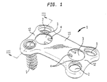
- FIG. 1 is a perspective view of an embodiment which does not form part of the invention;
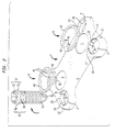
- FIG. 2 is an exploded perspective view of the embodiment of FIG. 1
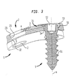
- FIG. 3 is a cross-sectional view along lines III-III of the embodiment of FIG. 1;
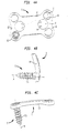
- FIG. 4a is a plan view from above of the embodiment of FIG. 1
- FIG. 4b is an elevation view of the embodiment shown in FIG. 4a;
- FIG. 4c is a front view of the embodiment shown in FIG. 4a;
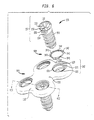
- FIG. 5 is a perspective view of an embodiment according to the invention;
- FIG. 6 is an exploded perspective view of the embodiment of FIG. 5:
- FIG. 7 is a partial view in section on the plane VII-VII of the embodiment of FIG. 5:
- FIG. 7a is a cross-sectional view of a bone screw or anchor of the present invention;
- FIG. 7b is a cross-sectional view of a single orifice used in the embodiment of FIG. 5 without the screw and split-ring along line VII - VII of FIG. 6.
- FIG. 7c is a plan view of the split-ring of the present invention;
- FIG. 7d is a cross-sectional view of the split-ring of FIG. 7c along lines A-A;
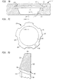
- FIG. 8a is a plan view of the invention;
- FIG. 8b is an elevation view of the embodiment shown in FIG. 8a;
- FIG. 8c is a front view of the embodiment shown in FIG. 8a;
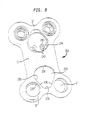
- FIG. 9 is a perspective view of another embodiment not according to the invention;
- FIG. 10 is a plan view of a screw driver for driving the bone screws of FIG. 7a from the orifice of FIG. 7b;
- FIG. 10a is an end view of the screw driver shown in FIG. 10;
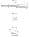
- FIG. 11 is a plan view of an extractor tube for extracting the anchor or bone screw from the plate after implantation;
- FIG.11a is an end view of the extractor shown in FIG. 11;
- FIG. 11b is an enlarged detail of the drive and of the extractor shown in FIG. 11; and
- FIG. 12 is a plan view of a threaded extraction shaft designed to engage the screw and pull it axially out of the hole, should it be impossible to unscrew the threaded shank.
-
- With reference to FIGS. 1 to 4c, there is shown an implant not according to the invention that comprises a
plate 1, bone screws 5 and circlips or split-rings 4. Theplate 1 is a bone plate such as an anterior cervical plate or any other plate designed to be held on bone by bone screws.Plate 1 may join two bone parts or stabilize a fracture or may sit on a resected bone surface such as on a tibial plateau. - In this embodiment,
plate 1 is formed of abody 11 ending in two ends 12 which have a width slightly greater than that of a mid-zone ofbody 11. Each of theends 12 compnses a pair of openings ororifices 2 which pass through the entire thickness ofplate 1. The four openings are arranged geometrically as at four corners of a rectangle. Each of theopenings 2 has a first, upper,cylindrical part 23 which continues in the form of a sphericalcentral part 21 and ends in a second, lower,cylindrical part 22, the diameter of which is smaller than that of the firstcylindrical part 23. The sphericalintermediate part 21 allows the angle of thebone screw 5 that is to be accommodated in theopening 2 to be chosen. -
Plate 1 preferably comprises twoblind holes 3 which have a circular opening and arecess 31. The twoblind holes 3 are arranged on the longitudinal mid-segment of the rectangle, near the respective pairs of corners.Recess 31 is such that it protrudes into the pair ofopenings 2 to which it is adjacent, thus creating anopen slot 32 in eachopening 2 of the pair. Thisslot 32 is made in such a way that it is located in the firstcylindrical part 23 of theopenings 2. -
Plate 1 has afirst curvature 13 in its longitudinal plane, as depicted in FIG. 4c. Thiscurvature 13 allowsplate 1 to follow the natural lordosis of the section of spine for which theplate 1 depicted in FIGS. 1 to 4c, is intended. In addition, theplate 1 has asecond curvature 14 in its transverse plane as depicted in FIG. 4b. Thiscurvature 14 allowsplate 1 to match as closely as possible the shape of the body of the vertebra to which it is connected. - Each
recess 31 is capable of housing a circlip 4. The circlip 4 is in the form of acircular ring 43 split at 42. The circlip or split-ring 4 comprises driving means 41 which, in this embodiment, are lugs projecting towards the inside of the ring. Each lug may be shaped to receive the tips of a pair of needle nose pliers (See FIG. 9). - Once in place in the
recess 31, with the circlip 4 in the position of rest, i.e. in the open position, it protrudes into the pair ofopenings 2 adjacent to it through theslot 32 of eachopening 2. It thus closes up theopening 2 slightly. - The
bone screw 5 is the preferred anchoring member in the embodiment which allows theplate 1 to be connected to the bodies of the vertebrae which are fitted with the present invention. Thepreferred screw 5 has ahead 57 surmounting a cylindrical part or shank with athread 51 suited for bone, comprising a self-tappingmeans 55 at its distal end. These tapping means allow the screw to better penetrate the bone when being driven. Thehead 57 comprises adrive 52 which, in this instance, is embodied by a hexagonal socket. In addition, thehead 57 comprises a slightlyconical part 53 which is continued in the form of apart 56 forming a rim extending towards the outside of thescrew 5 and inclined slightly with respect to a plane perpendicular to the axis A of thescrew 5. - Finally, the
head 57 of thescrew 5 ends in a sphericalmale part 54 which complements the femaleintermediate part 21 of theopening 2 and which meets the threaded cylindrical part orshank 51. These complementing forms allow thebone screw 5 to be set at a chosen angle with respect toplate 1. The anchoring ofplate 1 can thus be optimized by the surgeon during the operation. - Preferably, the implant of the present invention shown in FIGS. 1-4 is supplied to the surgeon with the two circlips 4 installed in
recesses 31 ofplate 1. If the plate is an anterior cervical plate, it is preferably implanted by an anterior access route and by uncovering the vertebral bodies that will be fitted. The surgeon positions theplate 1 then pierces pilot holes through each pair of openings where he wishes to have an anchorage. He then engages a bone screw in each pilot hole. He screws these in until thepart 54 of theirhead 5 comes into contact with the part of thering 44 of the circlip 4 that projects through theorifice 32. At this point, there are two possible options: - 1) The surgeon closes up the circlip 4 by bringing the two
lugs 41 closer together using pliers and then. holding the circlip closed, he screws the twobone screws 5 in until the complementaryspherical parts nm 56; - 2) The surgeon continues to screw in the anchoring
member 5. thespherical part 54 pushing thering 44 into theslot 32 through a ramp effect and thus forming its passage, and the ring will open again automatically once therim 56 has passed by, and the complementaryspherical parts -
- Locking is provided by contact between the complementary
spherical parts rim 56. The second role of therim 56 is to limit the possibilities of angular orientation. This prevents the screw from coming out of the vertebral body or from coming into contact with its counterpart fitted in theother opening 2 forming the pair. In both instances, the plate would be poorly anchored or even not anchored to the vertebral body at all. Thus, having introduced each screw into the orifice via its distal end, the circlip prevents the screw from backing out of the orifice. - In the event of an adjustment, the surgeon can easily withdraw the
plate 1 simply by unscrewing the bone screws 5 after having closed up the circlips 4 by moving theirlugs 41 closer together, thus uncovering the aperture of theorifice 2. - In the embodiment of the invention illustrated by FIGS. 5 to 8c,
cervical plate 1 is preferably still formed of abody 111 ending at twoends 112 which are slightly wider than thebody 111. Each of theends 112 still has a pair ofopenings 102 which pass right through the entire thickness of theplate 101. Eachopening 102 has afirst part 123 which is cylindrical. then a sphericalintermediate part 121. Preferably, the orifice oropening 102 has apart 122 in the form of an angular cutout in the lengthwise direction of theplate 101. Preferably. the cutout allows the screw to pivot an angle B. preferably from 0° to 20°. in the lengthwise direction aboutaxis 164, preferably the width of thecutout 122 is slightly less than its length. A circular recess or groove 131 is formed in thecylindrical part 123 of eachopening 102. As in the previous embodiment, when used as an anterior cervical plate, theplate 101 has acurvature 13 in its longitudinal plane and acurvature 14 in its transverse plane. The roles of these curvatures are the same as in the previous embodiment. - The
recess 131 is able to accommodate a circlip or split-ring 104. As before, thecirclip 104 is in the form of acircular ring 143, split at 142. The preferred circlip or split-ring 104 in this instance hastabs 141 andcutouts 149 distributed uniformly around the entire circumference of thering 143. Preferably, there are at least 3 of these tabs. They make it possible to be sure that the circlip will not escape from the groove orrecess 131, while leaving thinner parts of thering 143 to allow better flexibility when deforming or expanding the circlip as will be discussed hereinbelow. Of course it is possible to make the ring thinner or use other means to achieve flexibility in the ring. For example, one or two tabs could be used if the cutouts in the ring are sized sufficiently to produce the required flexibility. Thecirclip 104 comprises expansion chamfer orramp 144 in the form of an inlet chamfer located on theinterior side 145 of thering 143. - The
bone screw 105 differs from that of the previous embodiment in that thedrive 152 which is in the form of a cross is extended in one embodiment by ablind bore 158 coaxial with the axis A of thescrew 105. This allows the use of a screwdriver with a flat or cruciform blade extended by a small cylindrical protrusion that complements theblind bore 158. Thus, when tightening or loosening, the screwdriver cannot slip to injure nearby living tissues or irreversibly deform thecirclip 104. as this would compromise locking. - The
preferred head 157 has apart 153 which is generally conical and which slightly bows outwardly which is continued radially outward by apart 156 forming an upwardly facing rim surface extending towards the outside of thescrew 105 and which preferably is slightly inclined with respect to a plane perpendicular to the axis A of thescrew 105. - Finally, a part
spherical portion 154 that complements theintermediate part 121 of theopening 102 allows the outer edge of theportion 154 to meet the threaded cylindrical part orshank 151, which is threaded with a bone-screw thread. The purpose of this complementing nature is to allow the angle of thescrew 105 to be chosen with respect to theplate 101 in order to optimize anchorage. - As in the previous embodiment, the implant is supplied to the surgeon with the four split-rings or
circlips 104 installed in the fourrecesses 131 in theplate 101. As before, the surgeon, having made his access route, then positions theplate 101 and pierces the pilot holes through the pairs ofopenings 102 where he wishes to anchor, completely screws in the bone screws 105. At the end of tightening, thespherical part 154 will come into contact with thechamfer 144 of thecirclip 104 and then, through a bearing action, open up the latter to make its passage towards the sphericalintermediate part 121 of theorifice 102. Thecirclip 104 will close back up again automatically once therim 156 has passed, and the complementaryspherical parts - Performing these two operations makes sure that the
screw 105 is locked in theplate 101. As before, the second role of the upwardly facingrim 156 is to limit the possibilities of angular adjustment. This prevents the screw from coming out of the vertebral body or its threadedshank 151 from coming into contact with its counterpart fitted in theother orifice 102 forming the pair. In both instances the plate would be poorly anchored or not anchored to the vertebral body at all. In the event of an adjustment, the surgeon can easily withdraw theplate 101 simply by unscrewing the bone screws 105 after having opened upcirclip 104 as will be discussed below. - A preferred bone screw of the embodiment of the present invention is shown in greater detail in FIG. 7a. In the preferred embodiment, the
blind bore 158 ofscrew 105 is threaded for aportion 160 located belowdnve 152 towards thetip 161 of the screw. The function of the threaded portion will be described in greater detail below. - It should be noted that the
preferred screw 105 has a nominal thread diameter of about 4 mm with the outer diameter of the upwardly facingsurface rim 156 being about 5 mm. If desired, the leading end or tip 161 of thescrew shank 151 may include a groove or other structure for allowing the bone screw to be self-drilling and self-tapping. In this situation, no pilot hole need be drilled by the surgeon. - Referring to FIG. 7b, there is shown the
preferred opening 102 in the bone plate. The recess or groove 131 which accommodatesspring clip 104 has an upwardly and inwardlyinclined surface 133 which, in the preferred embodiment, extends at an angle of about 20° with respect to thebottom surface 135 ofgroove 131. In the preferred embodiment, thebottom surface 135 ofgroove 131 extends along a plane perpendicular to theaxis 164 of theopening 102. The upperinclined surface 133 is spaced fromsurface 135 bysurface 137 which, in the preferred embodiment, is about .3 mm. The maximum diameter to surface 137 ofgroove 131 is, in the preferred embodiment, about 6.9mm.Spherical seat 121 forscrew head 157 extends from adjacent the bottom bone contacting surface of the plate to surface 135. In the preferred embodiment, the spherical surface has a radius of 2.67 mm. Consequently, the partspherical portion 154 of the screw has a similar radius. As can be seen in FIG. 7b, theopening 102 may have an angular cutout along a portion ofsurface 122 adjacent the bottom plate surface to allow theshank 151 of the screw to extend in at least one direction at an angle B of approximately 0° to 20° and preferably 10° with respect to theaxis 164. Thus, when viewed from the bottom, the opening would appear to be oblong in at least one direction. Of course, the angular cutout can be enlarged to permit angulation in a plurality of directions. - Referring to FIG. 7c. there is shown a preferred split-ring or
circlip 104 which includes fivetabs 141 distributed uniformly around the circumference of thering 143. In the preferred embodiment, the ring has aninternal diameter 145 of approximately 4.5 mm and a maximumexternal diameter 147 of preferably 6.2 mm. The difference between theexternal diameter 147 and thegroove diameter 137 is preferably about 7 mm. This allows the internal diameter to expand to accommodate the screw head. The preferred cutouts have a depth of approximately .4 mm so that theexternal diameter 149 at each cutout is approximately 5.4 mm. Thepreferred split 142 is .26 mm in width when the split-ring is in its relaxed, i.e. unexpanded condition. The above dimensions are given for illustration only and larger screws, openings and split-rings may be used in other applications. - Referring to FIG. 7d, there is shown a cross-section of the split-ring shown in FIG. 7c along lines A-A. The split-ring has a
bottom surface 190 oriented to engage thebottom surface 135 ofgroove 131. The cross-section has an inclinedupper surface 192 for engagingsurface 133 which is upwardly inclined on moving towards the center the split-ring. Preferably, the incline is at an angle of about 20° with respect tobottom surface 190. The surface forminginternal diameter 145 is in two sections. the first issurface 194 which is generally parallel toaxis 164 ofopening 102 and the second issurface 144 which is angled radially outwardly towardssurface 192 also at preferably 20° with respect to surface 194 (and the axis 164).Surfaces radius 198 rather than a sharp comer. The preferred split-ring has an overall height from thesurface 190 to the top ofradius 198 of approximately .52 mm and the distance alongsurface 196 betweensurface - The preferred cross-section allows spring-
clip 104 to be assembled withingroove 131 by the plate manufacturer and shipped to the user in a pre-assembled condition. It is especially important that theclip 104 have a sufficient number of cutout areas to render it sufficiently flexible for insertion into the inserting recess or groove 131 prior to shipping to the end user. It is also necessary to use a relatively flexible material for the ring, which material has a modulus less than 100 GPa. Such a titanium material is found in U.S. patents 4,857,269 and 4,952,236. If these titanium alloys are utilized for the split-ring, it has been found that advantageous to make the joining member or plate and anchoring or bone screw out of the same material, although such is not absolutely necessary. In addition, polymeric materials can be used for the split-ring. In the preferred embodiment, thesplit ring 104 has no means for enabling its removal from the groove after assembly. Thus, it is not possible for the surgeon to remove the ring from the plate. - Another advantageous feature of the split-ring is the preferably 20° incline of the
top surface 192 which engages withcomplementary groove surface 133. This is advantageous because forces generated from the backing out of thescrew 105 against thebottom surface 190 of split-ring 104 tend to keep theinner diameter 145 from expanding. In addition, only a small annular inter-engagement between thebottom surface 190 ofring 104 and the upwardly facingsurface 156 is necessary to preventscrew 105 from backing out ofhole 2 inplate 1. In the preferred embodiment, this annular overlap is at least .07 mm and preferably between .07 mm on a radius and 11 mm. - In the embodiment not according to the invention illustrated in FIG. 9, the
device 201 differs from the first embodiment only in the shape of theblind holes 203 and of thecirclip 204 that can be housed in therecess 231. The shape of theholes 203 has asemicircular base 237 continued by twostraight surfaces 236 which converge towards each other and are connected at their other end of the side of the associated orifices by asemicircular vertex 235 of smaller radius than thebase 237. This shape facilities the fitting of thecirclip 204. The latter is very similar to the one in the first embodiment, except for thelugs 241 which haveholes 243 to take the jaws of a driving instrument. Installation with this embodiment is identical to that of the first embodiment. - The
circlip 104 may have a constant cross-section. - The bone screws may be monoaxial: they cannot be oriented with respect to the plate.
- It can thus be seen that, in the embodiments of FIGS. 1 and 9, one and the same circlip locks two anchoring screws.
- In all these embodiments, each circlip collaborates by direct contact with the screw to prevent it from coming out of the opening, without it being necessary to provide a part acting as an intermediate between the circlip and the screw.
- Referring to FIG. 10, there is shown a plan view of the
preferred screwdriver 300 not forming part of the present invention for drivingscrew 105. Thescrewdriver 300 includes ahandle 302, ashaft 304 and adrive head 306. Referring to FIG. 10a, there is shown an end view ofdrive head 306 showing a cruciform drive having a pair of mutuallyperpendicular blades 308.Blades 308 engagedrive 152 onscrew 105. In the preferred embodiment, the depth of the cruciformslot forming drive 152 is about 2 mm and the depth of thedrive blades 308 is somewhat less and the width of the fourslots forming drive 152 are about 1 mm with the width of theblades 308 being slightly less. This geometry ensures excellent engagement between the blades on thedriver 300 and thedrive 152. - Referring to FIGS. 11 through 11b, there is shown a tool not forming part of the present invention provided to remove the
screw 105 after it has been fully inserted into bone and blocked from backing out by split-ring 104. Referring to FIG. 11 there is shown anextraction tool 400 having ahandle 402 and atubular drive shaft 404, including adrive tip 406. Handle 402 is also tubular having acavity 408 open to anend 410 ofhandle 402. In the preferred embodiment, thecavity 408 is circular with a diameter of about 8 mm.Inner end 412 ofcavity 408 is open to acannulation 414 which extends the length ofshaft 404 and throughtip 406. In the preferred embodiment, this cannulation is circular with a diameter of about 2 mm. The function ofcannulation 414 is described below. - Referring to FIG. 11b, there is shown an enlarged view of
drive tip 406 ofextraction tube 400 which, likedriver head 306 previously described, includes a cruciform blade havingcross members 416 similar toblades 308. However, the outer diameter oftip 406 is equal to the outer diameter ofsurface 156 onscrew 105.Tip 406 includes an inwardly chamferedportion 418 which allowstip 406 to engage theinner diameter 145 of the split-ring and expand it sufficiently to allow the screw to be unthreaded or pulled back out throughinner diameter 145 by counter-rotation ofscrew 105 withextractor 400. Once the maximum diameter of upwardly facingsurface 156 passes through the split-ring, it springs inwardly alongsurface 154 ofscrew 105. - It has been found that in some instances, the bone deteriorates so that it is impossible to generate a screw removal force by the counter-rotation of
screw 105 withextractor 400. In this instance, referring to FIG. 12, there is shown anextraction tool 500 designed to fit within thecavity 408 andcannulation 414 ofextraction tool 400.Extraction tool 500 includes anupper portion 502, ashaft portion 504. a threadedtip 506 and anenlarged portion 508. The threaded tip includesthreads matching threads 160 inscrew 105. In the preferred embodiment, the thread is 1.6 mm in diameter. Thus, when thebone screw 105 cannot be removed merely by the counter-rotation ofscrew 105 withextraction tool 400,extraction shaft 504 is inserted through thecannulation 414 and outtip 406 thereof and into threaded engagement withthreads 160 ofbone screw 105. All the surgeon must then do is pull onportion 508 of theextraction tool 500 which pullsscrew 105 out of the bone.
Claims (8)
- An implant, particularly for the spinal column, comprising:wherein said at least one opening has a part spherical seat portion (121) located between said groove (131) and said bottom surface of said joining member and open to said surface to receive a shank (151) of said anchor, characterized in that said groove has a lower surface (135) nearest the bottom surface of the plate and an upper inclined surface (133) extending toward an upper surface of said plate and inwardly toward a central axis of said opening.a joining member (101) having a bone contacting surface and at least one opening (102) with a groove (131) formed around an inner circumference (123) of the opening;a bone-anchor (105) capable of being accommodated in the opening between said groove and said bone contacting surface; anda split-ring (104) mounted in said groove, the split-ring sized to expand upon insertion of the anchor element into the opening and to come into direct contact with a head (157) on the bone anchor to hold the bone anchor in the opening;
- The implant according to claim 1, wherein the joining member (101) comprises a plate.
- The implant according to claim 1, wherein the anchor includes a drive portion (152).
- The implant according to claim 1, wherein the split-ring (104) has a variable cross-section so as to optimize its flexibility.
- The implant according to claim 2, wherein the plate (101) has anatomical curvatures.
- The screw retaining system as set forth in claim 1, wherein said anchor (105) has a part spherical head portion (154) extending from said shank (151) towards said upwardly facing surface for engaging said spherical seat portion in said opening.
- The screw retaining system as set forth in claim 1, wherein the groove lower surface (135) is generally flat and extends generally perpendicular to said axis.
- The screw retaining system as set forth in claim 1, wherein said lower groove surface (135) is located closer to said upper plate surface than an upwardly facing surface on said screw when said part spherical head is seated in said part spherical portion.
Applications Claiming Priority (4)
| Application Number | Priority Date | Filing Date | Title |
|---|---|---|---|
| FR0008144A FR2810532B1 (en) | 2000-06-26 | 2000-06-26 | BONE IMPLANT WITH ANNULAR LOCKING MEANS |
| FR0008144 | 2000-06-26 | ||
| US09/665,530 US6602255B1 (en) | 2000-06-26 | 2000-09-19 | Bone screw retaining system |
| US665530 | 2000-09-19 |
Publications (3)
| Publication Number | Publication Date |
|---|---|
| EP1169971A2 EP1169971A2 (en) | 2002-01-09 |
| EP1169971A3 EP1169971A3 (en) | 2002-07-17 |
| EP1169971B1 true EP1169971B1 (en) | 2004-10-20 |
Family
ID=26212489
Family Applications (1)
| Application Number | Title | Priority Date | Filing Date |
|---|---|---|---|
| EP01401688A Expired - Lifetime EP1169971B1 (en) | 2000-06-26 | 2001-06-26 | Bone screw retaining system |
Country Status (6)
| Country | Link |
|---|---|
| US (5) | US20030093082A1 (en) |
| EP (1) | EP1169971B1 (en) |
| JP (1) | JP4792176B2 (en) |
| AU (1) | AU757023B2 (en) |
| CA (1) | CA2351231C (en) |
| DE (1) | DE60106525T2 (en) |
Cited By (14)
| Publication number | Priority date | Publication date | Assignee | Title |
|---|---|---|---|---|
| US7255699B2 (en) | 2001-12-14 | 2007-08-14 | Paul Kamaljit S | Spinal plate assembly |
| US7655009B2 (en) | 2003-12-01 | 2010-02-02 | Smith & Nephew, Inc. | Humeral nail |
| US7666185B2 (en) | 2003-09-03 | 2010-02-23 | Synthes Usa, Llc | Translatable carriage fixation system |
| US7905910B2 (en) | 2003-09-29 | 2011-03-15 | Smith & Nephew, Inc. | Bone plates and bone plate assemblies |
| US7931678B2 (en) | 2004-12-08 | 2011-04-26 | Depuy Spine, Inc. | Hybrid spinal plates |
| US8105367B2 (en) | 2003-09-29 | 2012-01-31 | Smith & Nephew, Inc. | Bone plate and bone plate assemblies including polyaxial fasteners |
| US8172885B2 (en) | 2003-02-05 | 2012-05-08 | Pioneer Surgical Technology, Inc. | Bone plate system |
| US8382807B2 (en) | 2005-07-25 | 2013-02-26 | Smith & Nephew, Inc. | Systems and methods for using polyaxial plates |
| US8562656B2 (en) | 2010-10-15 | 2013-10-22 | Warsaw Orrthopedic, Inc. | Retaining mechanism |
| US8623019B2 (en) | 2007-07-03 | 2014-01-07 | Pioneer Surgical Technology, Inc. | Bone plate system |
| US8795370B2 (en) | 2003-09-30 | 2014-08-05 | X-Spine Systems, Inc. | Fusion system and method for fusing spinal bones |
| US8900277B2 (en) | 2004-02-26 | 2014-12-02 | Pioneer Surgical Technology, Inc. | Bone plate system |
| US8940028B2 (en) | 2005-07-25 | 2015-01-27 | Smith & Nephew, Inc. | Systems and methods for using polyaxial plates |
| US9241749B2 (en) | 2002-10-28 | 2016-01-26 | Blackstone Medical, Inc. | Bone plate assembly provided with screw locking mechanisms |
Families Citing this family (133)
| Publication number | Priority date | Publication date | Assignee | Title |
|---|---|---|---|---|
| AU757023B2 (en) | 2000-06-26 | 2003-01-30 | Stryker European Holdings I, Llc | Bone screw retaining system |
| US20050010227A1 (en) | 2000-11-28 | 2005-01-13 | Paul Kamaljit S. | Bone support plate assembly |
| US7070599B2 (en) | 2002-07-24 | 2006-07-04 | Paul Kamaljit S | Bone support assembly |
| US7008426B2 (en) | 2001-12-14 | 2006-03-07 | Paul Kamaljit S | Bone treatment plate assembly |
| CA2471843C (en) * | 2001-12-24 | 2011-04-12 | Synthes (U.S.A.) | Device for osteosynthesis |
| US6695846B2 (en) * | 2002-03-12 | 2004-02-24 | Spinal Innovations, Llc | Bone plate and screw retaining mechanism |
| US8105366B2 (en) * | 2002-05-30 | 2012-01-31 | Warsaw Orthopedic, Inc. | Laminoplasty plate with flanges |
| US7004944B2 (en) | 2002-07-16 | 2006-02-28 | Sdgi Holdings, Inc. | Bone plate fastener retaining mechanisms and methods |
| US6989012B2 (en) * | 2002-07-16 | 2006-01-24 | Sdgi Holdings, Inc. | Plating system for stabilizing a bony segment |
| US7060067B2 (en) | 2002-08-16 | 2006-06-13 | Sdgi Holdings, Inc. | Systems, instrumentation and techniques for retaining fasteners relative to a bone plate |
| US7250054B2 (en) | 2002-08-28 | 2007-07-31 | Smith & Nephew, Inc. | Systems, methods, and apparatuses for clamping and reclamping an orthopedic surgical cable |
| US7309340B2 (en) | 2003-06-20 | 2007-12-18 | Medicinelodge, Inc. | Method and apparatus for bone plating |
| US7087057B2 (en) | 2003-06-27 | 2006-08-08 | Depuy Acromed, Inc. | Polyaxial bone screw |
| KR100552117B1 (en) * | 2003-07-22 | 2006-02-13 | 유앤아이 주식회사 | cervical spine fixator and driver |
| US7857839B2 (en) | 2003-09-03 | 2010-12-28 | Synthes Usa, Llc | Bone plate with captive clips |
| US7909860B2 (en) | 2003-09-03 | 2011-03-22 | Synthes Usa, Llc | Bone plate with captive clips |
| US9078706B2 (en) | 2003-09-30 | 2015-07-14 | X-Spine Systems, Inc. | Intervertebral fusion device utilizing multiple mobile uniaxial and bidirectional screw interface plates |
| US8821553B2 (en) | 2003-09-30 | 2014-09-02 | X-Spine Systems, Inc. | Spinal fusion system utilizing an implant plate having at least one integral lock |
| US8372152B2 (en) | 2003-09-30 | 2013-02-12 | X-Spine Systems, Inc. | Spinal fusion system utilizing an implant plate having at least one integral lock and ratchet lock |
| US7182782B2 (en) * | 2003-09-30 | 2007-02-27 | X-Spine Systems, Inc. | Spinal fusion system and method for fusing spinal bones |
| US8062367B2 (en) | 2003-09-30 | 2011-11-22 | X-Spine Systems, Inc. | Screw locking mechanism and method |
| US7740649B2 (en) | 2004-02-26 | 2010-06-22 | Pioneer Surgical Technology, Inc. | Bone plate system and methods |
| US20050216027A1 (en) * | 2004-03-24 | 2005-09-29 | Suh Sean S | Extraction screwdriver |
| US10478179B2 (en) * | 2004-04-27 | 2019-11-19 | Covidien Lp | Absorbable fastener for hernia mesh fixation |
| US7727266B2 (en) | 2004-06-17 | 2010-06-01 | Warsaw Orthopedic, Inc. | Method and apparatus for retaining screws in a plate |
| US8469966B2 (en) | 2004-09-23 | 2013-06-25 | Smith & Nephew, Inc. | Systems, methods, and apparatuses for tensioning an orthopedic surgical cable |
| US9615866B1 (en) | 2004-10-18 | 2017-04-11 | Nuvasive, Inc. | Surgical fixation system and related methods |
| US7935137B2 (en) | 2004-12-08 | 2011-05-03 | Depuy Spine, Inc. | Locking bone screw and spinal plate system |
| US8152838B2 (en) * | 2005-02-18 | 2012-04-10 | Alphatec Spine, Inc. | Orthopedic plate system and method for using the same |
| US8052729B2 (en) * | 2005-03-16 | 2011-11-08 | Stryker Spine | Anterior lumbar lag plate |
| US8470039B2 (en) | 2005-03-17 | 2013-06-25 | Spinal Elements, Inc. | Flanged interbody fusion device with fastener insert and retaining ring |
| AU2012211502B2 (en) * | 2005-03-17 | 2014-09-18 | Spinal Elements, Inc. | Implant and method for treating a spine |
| US7452370B2 (en) * | 2005-04-29 | 2008-11-18 | Warsaw Orthopedic, Inc | Apparatus for retaining a bone anchor in a bone plate and method for use thereof |
| US7288094B2 (en) * | 2005-06-10 | 2007-10-30 | Sdgi Holdings, Inc. | System and method for retaining screws relative to a vertebral plate |
| KR100656186B1 (en) | 2005-08-31 | 2006-12-13 | 주식회사 솔고 바이오메디칼 | Poly compressive fixation system |
| CA2626145A1 (en) * | 2005-10-25 | 2007-05-03 | Anthem Orthopaedics Llc | Bone fastening assembly and bushing and screw for use therewith |
| BRPI0620047A2 (en) * | 2005-12-21 | 2011-11-01 | Synthes Gmbh | bone plate set |
| US8100952B2 (en) * | 2005-12-22 | 2012-01-24 | Anthem Orthopaedics Llc | Drug delivering bone plate and method and targeting device for use therewith |
| US7771484B2 (en) * | 2006-02-28 | 2010-08-10 | Howmedica Osteonics Corp. | Modular tibial implant |
| WO2007109316A2 (en) * | 2006-03-21 | 2007-09-27 | Alphaspine, Inc. | Cervical pop rivet locking mechanism |
| US8303601B2 (en) * | 2006-06-07 | 2012-11-06 | Stryker Spine | Collet-activated distraction wedge inserter |
| US20120232595A1 (en) | 2011-03-07 | 2012-09-13 | Tyler HOLSCHLAG | Fastener retention system for spinal plates |
| ES2611609T3 (en) * | 2006-06-30 | 2017-05-09 | Alphatec Spine, Inc. | Bone fixation plate systems |
| US8361130B2 (en) | 2006-10-06 | 2013-01-29 | Depuy Spine, Inc. | Bone screw fixation |
| US8142432B2 (en) * | 2007-02-05 | 2012-03-27 | Synthes Usa, Llc | Apparatus for repositioning portions of fractured bone and method of using same |
| US8721693B2 (en) * | 2007-05-18 | 2014-05-13 | Us Spine, Inc. | Cervical plate locking mechanism and associated surgical method |
| US8840650B2 (en) * | 2007-05-18 | 2014-09-23 | Us Spine, Inc. | Cervical plate locking mechanism and associated surgical method |
| US9545275B2 (en) | 2007-05-18 | 2017-01-17 | Us Spine, Inc. | Medical device locking mechanisms and related methods and systems |
| US9072548B2 (en) * | 2007-06-07 | 2015-07-07 | Anthem Orthopaedics Llc | Spine repair assembly |
| US8361126B2 (en) | 2007-07-03 | 2013-01-29 | Pioneer Surgical Technology, Inc. | Bone plate system |
| US20090177239A1 (en) * | 2007-08-06 | 2009-07-09 | Michael Castro | Cervical plate instrument kit |
| US8343194B2 (en) * | 2007-08-20 | 2013-01-01 | Kamran Aflatoon | Anterior cervical staple |
| CN101835437A (en) | 2007-08-20 | 2010-09-15 | 纽文思公司 | Surgical fixation system and related methods |
| US8496693B2 (en) | 2007-10-16 | 2013-07-30 | Amendia Inc. | Bone screw retaining and removal system |
| US8998964B2 (en) | 2007-10-16 | 2015-04-07 | Spectrum Spine, LLC | Bone screw retaining and removal system |
| US20090149862A1 (en) * | 2007-12-10 | 2009-06-11 | Sym Partners, Llc | Guide pin for pedicle screw placement and method for use of such guide pin in spinal fusion surgeries |
| US8282675B2 (en) * | 2008-01-25 | 2012-10-09 | Depuy Spine, Inc. | Anti-backout mechanism |
| WO2009148421A1 (en) * | 2008-06-05 | 2009-12-10 | Seaspine, Inc. | Spinal fixation plate assembly |
| US20090326545A1 (en) * | 2008-06-26 | 2009-12-31 | Amedica Corporation | Systems and methods for inserting a bone anchor without a pilot hole |
| US8273111B2 (en) | 2008-07-02 | 2012-09-25 | Ebi, Llc | Growth control device |
| US8795340B2 (en) * | 2008-11-07 | 2014-08-05 | Globus Medical, Inc. | Vertical inline plate |
| US8821554B2 (en) | 2008-11-10 | 2014-09-02 | Amendia, Inc. | Method, system, and apparatus for mammalian bony segment stabilization |
| US20100121383A1 (en) * | 2008-11-10 | 2010-05-13 | Todd Stanaford | Method, system, and apparatus for mammalian bony segment stabilization |
| US20100217399A1 (en) * | 2009-02-22 | 2010-08-26 | Groh Gordon I | Base plate system for shoulder arthroplasty and method of using the same |
| JP5548710B2 (en) | 2009-03-13 | 2014-07-16 | スパイナル シンプリシティ エルエルシー | Dynamic spine plate system |
| US8574270B2 (en) | 2009-03-13 | 2013-11-05 | Spinal Simplicity Llc | Bone plate assembly with bone screw retention features |
| US9220547B2 (en) * | 2009-03-27 | 2015-12-29 | Spinal Elements, Inc. | Flanged interbody fusion device |
| CH700839A2 (en) * | 2009-04-20 | 2010-10-29 | Creaholic Sa | Fixing device for surgical mounting system. |
| US9095444B2 (en) | 2009-07-24 | 2015-08-04 | Warsaw Orthopedic, Inc. | Implant with an interference fit fastener |
| FR2948553B1 (en) * | 2009-07-30 | 2012-06-08 | Clariance | ANTI-RETRACTOR DEVICE WITH DRAWERS FOR PROSTHESIS |
| USD754857S1 (en) | 2009-10-14 | 2016-04-26 | Nuvasive, Inc. | Bone plate |
| EP3398544B1 (en) * | 2009-10-21 | 2020-02-19 | International Spinal Innovations, LLC | Spinal plate with compression locking |
| US20110106157A1 (en) * | 2009-10-30 | 2011-05-05 | Warsaw Orthropedic, Inc. | Self-Locking Interference Bone Screw for use with Spinal Implant |
| US8756819B2 (en) * | 2010-04-12 | 2014-06-24 | Bettcher Industries, Inc. | Power operated rotary knife with disposable blade support assembly |
| US8858603B1 (en) | 2010-06-09 | 2014-10-14 | Choice Spine, L.P. | Cervical plate with screw retention clip |
| BR112013003543A2 (en) * | 2010-08-17 | 2016-06-28 | Redyns Medical Llc | method and apparatus for attaching soft tissue to bone |
| US9657766B2 (en) | 2010-09-14 | 2017-05-23 | Enduralock, Llc | Tools and ratchet locking mechanisms for threaded fasteners |
| US8784027B2 (en) | 2010-09-14 | 2014-07-22 | Enduralock, Llc | Ratchet locking mechanism for threaded fastener |
| US8940030B1 (en) | 2011-01-28 | 2015-01-27 | Nuvasive, Inc. | Spinal fixation system and related methods |
| US8668723B2 (en) | 2011-07-19 | 2014-03-11 | Neurostructures, Inc. | Anterior cervical plate |
| US9351768B2 (en) * | 2011-08-26 | 2016-05-31 | Life Spine, Inc. | Bone screw retention in a spinal implant |
| US11123117B1 (en) | 2011-11-01 | 2021-09-21 | Nuvasive, Inc. | Surgical fixation system and related methods |
| US8784459B2 (en) | 2012-01-17 | 2014-07-22 | Genesys Spine | Spinal plate and locking screw devices, methods, and systems |
| US8734495B2 (en) * | 2012-01-18 | 2014-05-27 | Globus Medical, Inc. | Securing fasteners |
| US8974504B2 (en) | 2012-05-10 | 2015-03-10 | Spinal Simplicity Llc | Dynamic bone fracture plates |
| US20140039554A1 (en) * | 2012-08-03 | 2014-02-06 | Seo-Kon Kim | Apparatus for fixing a cervical spine having self tension part |
| KR101331429B1 (en) * | 2012-08-03 | 2013-11-21 | 주식회사 솔고 바이오메디칼 | Snap type fixing apparatus for cervical spine |
| US9480475B2 (en) | 2012-08-15 | 2016-11-01 | DePuy Synthes Products, Inc. | Bone plate suture anchor |
| US20150245859A1 (en) * | 2012-10-19 | 2015-09-03 | Deroyal Industries, Inc. | Cervical Plate With Retaining Clip |
| US9642652B2 (en) * | 2013-02-13 | 2017-05-09 | Choice Spine, Lp | Variable angle bone plate with semi-constrained articulating screw |
| JP5510874B1 (en) * | 2013-03-11 | 2014-06-04 | 多摩メディカル有限会社 | Medical screw and jig for removing medical screw |
| US9943341B2 (en) | 2013-07-16 | 2018-04-17 | K2M, Llc | Retention plate member for a spinal plate system |
| US9510880B2 (en) | 2013-08-13 | 2016-12-06 | Zimmer, Inc. | Polyaxial locking mechanism |
| US9468479B2 (en) | 2013-09-06 | 2016-10-18 | Cardinal Health 247, Inc. | Bone plate |
| US9629664B2 (en) | 2014-01-20 | 2017-04-25 | Neurostructures, Inc. | Anterior cervical plate |
| US9486250B2 (en) | 2014-02-20 | 2016-11-08 | Mastros Innovations, LLC. | Lateral plate |
| US9421053B2 (en) | 2014-05-08 | 2016-08-23 | Titan Spine, Llc | Implant fixation assemblies having a screw and C-shaped fixation collar |
| US9913672B2 (en) | 2014-05-28 | 2018-03-13 | Genesys Spine | Resiliant spinal plate system |
| JP2018502693A (en) | 2015-01-27 | 2018-02-01 | スパイナル・エレメンツ・インコーポレーテッド | Facet joint implant |
| WO2016137983A1 (en) | 2015-02-24 | 2016-09-01 | X-Spine Systems, Inc. | Modular interspinous fixation system with threaded component |
| CA2981885C (en) | 2015-04-17 | 2023-09-26 | Enduralock, Llc | Locking fastener with deflectable lock |
| US10215217B2 (en) | 2015-04-17 | 2019-02-26 | Enduralock, Llc | Locking fastener with deflectable lock |
| US10801540B2 (en) | 2015-04-17 | 2020-10-13 | Enduralock, Llc | Locking mechanisms with deflectable lock member |
| CA3033078A1 (en) | 2015-09-08 | 2017-03-16 | Enduralock, Llc | Locking mechanisms with deflectable washer members |
| KR101720142B1 (en) * | 2016-01-18 | 2017-03-27 | 주식회사 메타바이오메드 | Fixing apparatus of cervical spine |
| CN105997229B (en) * | 2016-05-03 | 2018-08-31 | 浙江曹娥电机制造有限公司 | Device for fetching nail for orthopaedics |
| US10426535B2 (en) | 2017-01-05 | 2019-10-01 | Stryker European Holdings I, Llc | Self-holding screw head |
| US10980641B2 (en) | 2017-05-04 | 2021-04-20 | Neurostructures, Inc. | Interbody spacer |
| US10512547B2 (en) | 2017-05-04 | 2019-12-24 | Neurostructures, Inc. | Interbody spacer |
| US11234742B2 (en) | 2017-11-16 | 2022-02-01 | Globus Medical, Inc. | Anterior cervical plate assembly |
| US11272963B2 (en) | 2017-11-16 | 2022-03-15 | Globus Medical, Inc. | Anterior cervical plate assembly |
| US11229460B2 (en) | 2017-11-16 | 2022-01-25 | Globus Medical, Inc. | Anterior cervical plate assembly |
| US11304734B2 (en) | 2017-11-16 | 2022-04-19 | Globus Medical Inc. | Anterior cervical plate assembly |
| US20210000509A1 (en) * | 2018-03-02 | 2021-01-07 | Scot Hodkiewicz | Pin fastener with removeable drill bit for bone fixator |
| EP4108194A1 (en) | 2018-03-02 | 2022-12-28 | Stryker European Holdings I, LLC | Bone plates and associated screws |
| US11076892B2 (en) * | 2018-08-03 | 2021-08-03 | Neurostructures, Inc. | Anterior cervical plate |
| BR112021005206A2 (en) | 2018-09-20 | 2021-06-08 | Spinal Elements, Inc. | spinal implant device |
| AU2019346607A1 (en) * | 2018-09-27 | 2021-05-20 | Triqueue Holdings, Llc | Implant systems, plates, bone fusion systems, and methods employing same |
| US11071629B2 (en) | 2018-10-13 | 2021-07-27 | Neurostructures Inc. | Interbody spacer |
| JP7281160B2 (en) * | 2018-10-30 | 2023-05-25 | 株式会社ホムズ技研 | bone fixation system |
| US11111950B2 (en) | 2019-04-01 | 2021-09-07 | Enduralock, Llc | Locking mechanisms with deflectable lock member |
| US11857224B2 (en) * | 2019-06-30 | 2024-01-02 | Innovasis, Inc. | Bone plate |
| US10743922B1 (en) | 2019-09-27 | 2020-08-18 | Trilliant Surgical Llc | Variable angle locking construct for orthopedic applications |
| US11173042B2 (en) | 2019-11-26 | 2021-11-16 | GetSet Surgical SA | Spinal surgery devices, systems, and methods |
| USD925740S1 (en) | 2019-11-26 | 2021-07-20 | GetSet Surgical SA | Spinal fusion cage |
| US11273057B2 (en) | 2019-11-26 | 2022-03-15 | GetSet Surgical SA | Spinal surgery instruments, systems, and methods |
| US11278426B2 (en) | 2019-11-26 | 2022-03-22 | GetSet Surgical SA | Spinal surgery assemblies, systems, and methods |
| US11877779B2 (en) | 2020-03-26 | 2024-01-23 | Xtant Medical Holdings, Inc. | Bone plate system |
| US11382761B2 (en) | 2020-04-11 | 2022-07-12 | Neurostructures, Inc. | Expandable interbody spacer |
| US11304817B2 (en) | 2020-06-05 | 2022-04-19 | Neurostructures, Inc. | Expandable interbody spacer |
| USD949341S1 (en) | 2020-09-29 | 2022-04-19 | Trilliant Surgical Llc | Bone fixation plate |
| US11911284B2 (en) | 2020-11-19 | 2024-02-27 | Spinal Elements, Inc. | Curved expandable interbody devices and deployment tools |
| US11717419B2 (en) | 2020-12-10 | 2023-08-08 | Neurostructures, Inc. | Expandable interbody spacer |
Family Cites Families (68)
| Publication number | Priority date | Publication date | Assignee | Title |
|---|---|---|---|---|
| US872897A (en) | 1907-08-31 | 1907-12-03 | John W Chapman | Nut-lock. |
| US2248054A (en) * | 1939-06-07 | 1941-07-08 | Becker Joseph | Screw driver |
| US2620000A (en) * | 1950-10-14 | 1952-12-02 | Harold E Noffsinger | Screw holding attachment for screw drivers |
| US3741205A (en) | 1971-06-14 | 1973-06-26 | K Markolf | Bone fixation plate |
| DE2554555C2 (en) * | 1973-05-31 | 1984-06-14 | Waldes Kohinoor Inc., Long Island, N.Y. | Circlip |
| JPS5632650Y2 (en) * | 1975-03-25 | 1981-08-03 | ||
| JPS51119455A (en) | 1975-04-12 | 1976-10-20 | Katsuyuki Totsu | Improved screw |
| US4877020A (en) * | 1984-11-30 | 1989-10-31 | Vich Jose M O | Apparatus for bone graft |
| DE8513288U1 (en) | 1985-05-06 | 1986-09-04 | Wolter, Dietmar, Prof. Dr., 2000 Hamburg | Osteosynthesis plate |
| JPS63157458A (en) | 1986-12-22 | 1988-06-30 | Tokuriki Honten Co Ltd | Lead pin |
| CA1333209C (en) | 1988-06-28 | 1994-11-29 | Gary Karlin Michelson | Artificial spinal fusion implants |
| US4952236A (en) * | 1988-09-09 | 1990-08-28 | Pfizer Hospital Products Group, Inc. | Method of making high strength, low modulus, ductile, biocompatible titanium alloy |
| US4857269A (en) * | 1988-09-09 | 1989-08-15 | Pfizer Hospital Products Group Inc. | High strength, low modulus, ductile, biopcompatible titanium alloy |
| JPH0631215Y2 (en) * | 1988-11-30 | 1994-08-22 | 京セラ株式会社 | Screw removal prevention mechanism |
| IT1232572B (en) | 1989-02-10 | 1992-02-26 | Calderale Pasquale Mario | MEANS OF OSTEOSYNTHESIS FOR THE CONNECTION OF BONE FRACTURE SEGMENTS |
| US5041116A (en) | 1990-05-21 | 1991-08-20 | Wilson James T | Compression hip screw system |
| US5797918A (en) * | 1991-12-13 | 1998-08-25 | David A. McGuire | Flexible surgical screwdriver and methods of arthroscopic ligament reconstruction |
| CA2109907C (en) | 1992-11-25 | 2000-01-25 | Ronald A. Yapp | Osteosynthesis plate system |
| US5364399A (en) * | 1993-02-05 | 1994-11-15 | Danek Medical, Inc. | Anterior cervical plating system |
| US5423826A (en) | 1993-02-05 | 1995-06-13 | Danek Medical, Inc. | Anterior cervical plate holder/drill guide and method of use |
| US5431660A (en) * | 1993-11-30 | 1995-07-11 | Burke; Dennis W. | Spring loaded screw and driver/extractor therefor |
| US5885299A (en) * | 1994-09-15 | 1999-03-23 | Surgical Dynamics, Inc. | Apparatus and method for implant insertion |
| JP3501542B2 (en) * | 1995-04-07 | 2004-03-02 | 富久 腰野 | Medical hard tissue replacements and artificial joints |
| US5520690A (en) * | 1995-04-13 | 1996-05-28 | Errico; Joseph P. | Anterior spinal polyaxial locking screw plate assembly |
| US5578034A (en) * | 1995-06-07 | 1996-11-26 | Danek Medical, Inc. | Apparatus for preventing screw backout in a bone plate fixation system |
| DE29521456U1 (en) | 1995-12-07 | 1997-05-07 | Aesculap Ag | Orthopedic retention system |
| GB9613916D0 (en) * | 1996-07-03 | 1996-09-04 | Dall Vagn E | Cortical bone screw |
| DE69838856T2 (en) * | 1997-02-11 | 2008-12-11 | Warsaw Orthopedic, Inc., Warsaw | Plate for the anterior cervical spine with fixation system for one screw |
| JP4467647B2 (en) | 1997-02-11 | 2010-05-26 | ウォーソー・オーソペディック・インコーポレーテッド | Bone plating system |
| ZA983955B (en) | 1997-05-15 | 2001-08-13 | Sdgi Holdings Inc | Anterior cervical plating system. |
| US6454769B2 (en) * | 1997-08-04 | 2002-09-24 | Spinal Concepts, Inc. | System and method for stabilizing the human spine with a bone plate |
| CA2311803A1 (en) | 1997-10-24 | 1999-05-06 | Robert S. Bray, Jr. | Bone plate and bone screw guide mechanism |
| US5951558A (en) | 1998-04-22 | 1999-09-14 | Fiz; Daniel | Bone fixation device |
| FR2778088B1 (en) | 1998-04-30 | 2000-09-08 | Materiel Orthopedique En Abreg | ANTERIOR IMPLANT, PARTICULARLY FOR THE CERVICAL RACHIS |
| US6533786B1 (en) | 1999-10-13 | 2003-03-18 | Sdgi Holdings, Inc. | Anterior cervical plating system |
| US20040220571A1 (en) | 1998-04-30 | 2004-11-04 | Richard Assaker | Bone plate assembly |
| US6258089B1 (en) * | 1998-05-19 | 2001-07-10 | Alphatec Manufacturing, Inc. | Anterior cervical plate and fixation system |
| US6090111A (en) * | 1998-06-17 | 2000-07-18 | Surgical Dynamics, Inc. | Device for securing spinal rods |
| US6436100B1 (en) * | 1998-08-07 | 2002-08-20 | J. Lee Berger | Cannulated internally threaded bone screw and reduction driver device |
| FR2784570B1 (en) | 1998-10-19 | 2001-02-16 | Scient X | INTERVERTEBRAL CONNECTION DEVICE HAVING ANTI-EXTRACTION MEANS FOR ANCHORAGE SCREWS |
| US7094239B1 (en) | 1999-05-05 | 2006-08-22 | Sdgi Holdings, Inc. | Screws of cortical bone and method of manufacture thereof |
| FR2794963B1 (en) * | 1999-06-17 | 2001-09-07 | Eurosurgical | ANTI-KICKBACK DEVICE FOR ORTHOPEDIC IMPLANT |
| US6261291B1 (en) * | 1999-07-08 | 2001-07-17 | David J. Talaber | Orthopedic implant assembly |
| US6224602B1 (en) | 1999-10-11 | 2001-05-01 | Interpore Cross International | Bone stabilization plate with a secured-locking mechanism for cervical fixation |
| US6602256B1 (en) | 1999-10-11 | 2003-08-05 | Cross Medical Products, Inc. | Bone stabilization plate with a secured-locking mechanism for cervical fixation |
| US6692503B2 (en) | 1999-10-13 | 2004-02-17 | Sdgi Holdings, Inc | System and method for securing a plate to the spinal column |
| US6331179B1 (en) * | 2000-01-06 | 2001-12-18 | Spinal Concepts, Inc. | System and method for stabilizing the human spine with a bone plate |
| US6440136B1 (en) * | 2000-05-24 | 2002-08-27 | Medtronic Ps Medical, Inc. | Apparatus for attaching to bone |
| AU757023B2 (en) | 2000-06-26 | 2003-01-30 | Stryker European Holdings I, Llc | Bone screw retaining system |
| FR2810532B1 (en) * | 2000-06-26 | 2003-05-30 | Stryker Spine Sa | BONE IMPLANT WITH ANNULAR LOCKING MEANS |
| WO2002003885A2 (en) | 2000-07-10 | 2002-01-17 | Michelson Gary K | Flanged interbody spinal fusion implants |
| US6605090B1 (en) | 2000-10-25 | 2003-08-12 | Sdgi Holdings, Inc. | Non-metallic implant devices and intra-operative methods for assembly and fixation |
| US6503250B2 (en) | 2000-11-28 | 2003-01-07 | Kamaljit S. Paul | Bone support assembly |
| US20050010227A1 (en) | 2000-11-28 | 2005-01-13 | Paul Kamaljit S. | Bone support plate assembly |
| US6413259B1 (en) | 2000-12-14 | 2002-07-02 | Blackstone Medical, Inc | Bone plate assembly including a screw retaining member |
| TW499953U (en) * | 2000-12-19 | 2002-08-21 | Jr-Yi Lin | Spine fastening reposition device |
| FR2823096B1 (en) | 2001-04-06 | 2004-03-19 | Materiel Orthopedique En Abreg | PLATE FOR LTE AND LTE VERTEBRATE OSTEOSYNTHESIS DEVICE, OSTEOSYNTHESIS DEVICE INCLUDING SUCH A PLATE, AND INSTRUMENT FOR LAYING SUCH A PLATE |
| US6599290B2 (en) * | 2001-04-17 | 2003-07-29 | Ebi, L.P. | Anterior cervical plating system and associated method |
| JP4283665B2 (en) | 2001-06-04 | 2009-06-24 | ウォーソー・オーソペディック・インコーポレーテッド | Dynamic plate for anterior cervical spine with movable segments |
| US7097645B2 (en) | 2001-06-04 | 2006-08-29 | Sdgi Holdings, Inc. | Dynamic single-lock anterior cervical plate system having non-detachably fastened and moveable segments |
| US7186256B2 (en) | 2001-06-04 | 2007-03-06 | Warsaw Orthopedic, Inc. | Dynamic, modular, single-lock anterior cervical plate system having assembleable and movable segments |
| US7044952B2 (en) | 2001-06-06 | 2006-05-16 | Sdgi Holdings, Inc. | Dynamic multilock anterior cervical plate system having non-detachably fastened and moveable segments |
| US7041105B2 (en) | 2001-06-06 | 2006-05-09 | Sdgi Holdings, Inc. | Dynamic, modular, multilock anterior cervical plate system having detachably fastened assembleable and moveable segments |
| US6890335B2 (en) | 2001-08-24 | 2005-05-10 | Zimmer Spine, Inc. | Bone fixation device |
| US6755833B1 (en) | 2001-12-14 | 2004-06-29 | Kamaljit S. Paul | Bone support assembly |
| US7008426B2 (en) | 2001-12-14 | 2006-03-07 | Paul Kamaljit S | Bone treatment plate assembly |
| US7070599B2 (en) | 2002-07-24 | 2006-07-04 | Paul Kamaljit S | Bone support assembly |
| US7524325B2 (en) * | 2002-11-04 | 2009-04-28 | Farid Bruce Khalili | Fastener retention system |
-
2001
- 2001-06-25 AU AU54037/01A patent/AU757023B2/en not_active Ceased
- 2001-06-26 EP EP01401688A patent/EP1169971B1/en not_active Expired - Lifetime
- 2001-06-26 JP JP2001192408A patent/JP4792176B2/en not_active Expired - Fee Related
- 2001-06-26 DE DE60106525T patent/DE60106525T2/en not_active Expired - Lifetime
- 2001-06-26 CA CA002351231A patent/CA2351231C/en not_active Expired - Fee Related
-
2002
- 2002-12-30 US US10/331,212 patent/US20030093082A1/en not_active Abandoned
-
2005
- 2005-02-17 US US11/060,171 patent/US7887547B2/en not_active Expired - Fee Related
-
2011
- 2011-01-06 US US12/985,733 patent/US8287550B2/en not_active Expired - Lifetime
-
2012
- 2012-09-20 US US13/623,269 patent/US8734496B2/en not_active Expired - Fee Related
-
2014
- 2014-05-08 US US14/272,922 patent/US9186189B2/en not_active Expired - Fee Related
Cited By (26)
| Publication number | Priority date | Publication date | Assignee | Title |
|---|---|---|---|---|
| US7255699B2 (en) | 2001-12-14 | 2007-08-14 | Paul Kamaljit S | Spinal plate assembly |
| US9241749B2 (en) | 2002-10-28 | 2016-01-26 | Blackstone Medical, Inc. | Bone plate assembly provided with screw locking mechanisms |
| US8172885B2 (en) | 2003-02-05 | 2012-05-08 | Pioneer Surgical Technology, Inc. | Bone plate system |
| US9414870B2 (en) | 2003-09-03 | 2016-08-16 | DePuy Synthes Products, Inc. | Translatable carriage fixation system |
| US7666185B2 (en) | 2003-09-03 | 2010-02-23 | Synthes Usa, Llc | Translatable carriage fixation system |
| US8262659B2 (en) | 2003-09-03 | 2012-09-11 | Synthes Usa, Llc | Translatable carriage fixation system |
| US7905910B2 (en) | 2003-09-29 | 2011-03-15 | Smith & Nephew, Inc. | Bone plates and bone plate assemblies |
| US7909858B2 (en) | 2003-09-29 | 2011-03-22 | Smith & Nephew, Inc. | Bone plate systems using provisional fixation |
| US8105367B2 (en) | 2003-09-29 | 2012-01-31 | Smith & Nephew, Inc. | Bone plate and bone plate assemblies including polyaxial fasteners |
| US8992581B2 (en) | 2003-09-29 | 2015-03-31 | Smith & Nephew, Inc. | Bone plate and bone plate assemblies including polyaxial fasteners |
| US8795370B2 (en) | 2003-09-30 | 2014-08-05 | X-Spine Systems, Inc. | Fusion system and method for fusing spinal bones |
| US7655009B2 (en) | 2003-12-01 | 2010-02-02 | Smith & Nephew, Inc. | Humeral nail |
| US8900277B2 (en) | 2004-02-26 | 2014-12-02 | Pioneer Surgical Technology, Inc. | Bone plate system |
| US7931678B2 (en) | 2004-12-08 | 2011-04-26 | Depuy Spine, Inc. | Hybrid spinal plates |
| US8888824B2 (en) | 2005-07-25 | 2014-11-18 | Smith & Nephew, Inc. | Systems and methods for using polyaxial plates |
| US8940028B2 (en) | 2005-07-25 | 2015-01-27 | Smith & Nephew, Inc. | Systems and methods for using polyaxial plates |
| US8382807B2 (en) | 2005-07-25 | 2013-02-26 | Smith & Nephew, Inc. | Systems and methods for using polyaxial plates |
| US10080598B2 (en) | 2005-07-25 | 2018-09-25 | Smith & Nephew, Inc. | Systems and methods for using polyaxial plates |
| US10092337B2 (en) | 2005-07-25 | 2018-10-09 | Smith & Nephew, Inc. | Systems and methods for using polyaxial plates |
| US10292741B2 (en) | 2005-07-25 | 2019-05-21 | Smith & Nephew, Inc. | Systems and methods for using polyaxial plates |
| US10327822B2 (en) | 2005-07-25 | 2019-06-25 | Smith & Nephew, Inc. | Systems and methods for using polyaxial plates |
| US10736680B2 (en) | 2005-07-25 | 2020-08-11 | Smith & Nephew, Inc. | Systems and methods for using polyaxial plates |
| US11896270B2 (en) | 2005-07-25 | 2024-02-13 | Smith & Nephew, Inc. | Systems and methods for using polyaxial plates |
| US8623019B2 (en) | 2007-07-03 | 2014-01-07 | Pioneer Surgical Technology, Inc. | Bone plate system |
| US9381046B2 (en) | 2007-07-03 | 2016-07-05 | Pioneer Surgical Technology, Inc. | Bone plate system |
| US8562656B2 (en) | 2010-10-15 | 2013-10-22 | Warsaw Orrthopedic, Inc. | Retaining mechanism |
Also Published As
| Publication number | Publication date |
|---|---|
| CA2351231C (en) | 2006-04-04 |
| AU757023B2 (en) | 2003-01-30 |
| US9186189B2 (en) | 2015-11-17 |
| US20130066379A1 (en) | 2013-03-14 |
| EP1169971A2 (en) | 2002-01-09 |
| EP1169971A3 (en) | 2002-07-17 |
| DE60106525T2 (en) | 2005-10-13 |
| US8734496B2 (en) | 2014-05-27 |
| DE60106525D1 (en) | 2004-11-25 |
| US20050149027A1 (en) | 2005-07-07 |
| US20110152944A1 (en) | 2011-06-23 |
| US7887547B2 (en) | 2011-02-15 |
| US8287550B2 (en) | 2012-10-16 |
| AU5403701A (en) | 2002-01-03 |
| JP4792176B2 (en) | 2011-10-12 |
| US20140243909A1 (en) | 2014-08-28 |
| US20030093082A1 (en) | 2003-05-15 |
| JP2002143176A (en) | 2002-05-21 |
| CA2351231A1 (en) | 2001-12-26 |
Similar Documents
| Publication | Publication Date | Title |
|---|---|---|
| EP1169971B1 (en) | Bone screw retaining system | |
| US6602255B1 (en) | Bone screw retaining system | |
| US9730804B2 (en) | Locking spinal fusion device | |
| US8672985B2 (en) | Bone fasteners and method for stabilizing vertebral bone facets using the bone fasteners | |
| EP1848353B1 (en) | Orthopedic plate system | |
| EP2254493B1 (en) | Variable axis locking mechanism for use in orthopedic implants | |
| US6402756B1 (en) | Longitudinal plate assembly having an adjustable length | |
| JP4584876B2 (en) | Fixing assembly | |
| US8460348B2 (en) | Locking bone screw and spinal plate system | |
| EP2124789B1 (en) | Spine plate with bone screw relief area | |
| US7819902B2 (en) | Medialised rod pedicle screw assembly | |
| US9414874B2 (en) | Low profile fastening assembly | |
| US9987057B2 (en) | Orthopedic anchor assembly | |
| US8911483B2 (en) | Compliant cervical screw locking mechanism | |
| JP2002535068A (en) | Surgical fastener assembly | |
| JP2013501580A (en) | Spinous process fixation graft | |
| JP2006081914A (en) | Surgical fastening device assembly |
Legal Events
| Date | Code | Title | Description |
|---|---|---|---|
| PUAI | Public reference made under article 153(3) epc to a published international application that has entered the european phase |
Free format text: ORIGINAL CODE: 0009012 |
|
| AK | Designated contracting states |
Kind code of ref document: A2 Designated state(s): AT BE CH CY DE DK ES FI FR GB GR IE IT LI LU MC NL PT SE TR |
|
| AX | Request for extension of the european patent |
Free format text: AL;LT;LV;MK;RO;SI |
|
| PUAL | Search report despatched |
Free format text: ORIGINAL CODE: 0009013 |
|
| AK | Designated contracting states |
Kind code of ref document: A3 Designated state(s): AT BE CH CY DE DK ES FI FR GB GR IE IT LI LU MC NL PT SE TR |
|
| AX | Request for extension of the european patent |
Free format text: AL;LT;LV;MK;RO;SI |
|
| 17P | Request for examination filed |
Effective date: 20021230 |
|
| AKX | Designation fees paid |
Designated state(s): CH DE FR GB IT LI |
|
| 17Q | First examination report despatched |
Effective date: 20030507 |
|
| GRAP | Despatch of communication of intention to grant a patent |
Free format text: ORIGINAL CODE: EPIDOSNIGR1 |
|
| GRAS | Grant fee paid |
Free format text: ORIGINAL CODE: EPIDOSNIGR3 |
|
| GRAA | (expected) grant |
Free format text: ORIGINAL CODE: 0009210 |
|
| AK | Designated contracting states |
Kind code of ref document: B1 Designated state(s): CH DE FR GB IT LI |
|
| REG | Reference to a national code |
Ref country code: GB Ref legal event code: FG4D |
|
| REG | Reference to a national code |
Ref country code: CH Ref legal event code: EP |
|
| REG | Reference to a national code |
Ref country code: IE Ref legal event code: FG4D |
|
| REF | Corresponds to: |
Ref document number: 60106525 Country of ref document: DE Date of ref document: 20041125 Kind code of ref document: P |
|
| REG | Reference to a national code |
Ref country code: CH Ref legal event code: NV Representative=s name: MICHELI & CIE INGENIEURS-CONSEILS |
|
| RAP2 | Party data changed (patent owner data changed or rights of a patent transferred) |
Owner name: STRYKER SPINE |
|
| ET | Fr: translation filed | ||
| REG | Reference to a national code |
Ref country code: CH Ref legal event code: PFA Owner name: STRYKER SPINE Free format text: STRYKER SPINE SA#ZI DE MARTICOT#33610 CESTAS (FR) -TRANSFER TO- STRYKER SPINE#ZI DE MARTICOT#33610 CESTAS (FR) |
|
| PLBE | No opposition filed within time limit |
Free format text: ORIGINAL CODE: 0009261 |
|
| STAA | Information on the status of an ep patent application or granted ep patent |
Free format text: STATUS: NO OPPOSITION FILED WITHIN TIME LIMIT |
|
| 26N | No opposition filed |
Effective date: 20050721 |
|
| REG | Reference to a national code |
Ref country code: FR Ref legal event code: RM |
|
| PGFP | Annual fee paid to national office [announced via postgrant information from national office to epo] |
Ref country code: IT Payment date: 20070620 Year of fee payment: 7 |
|
| PG25 | Lapsed in a contracting state [announced via postgrant information from national office to epo] |
Ref country code: IT Free format text: LAPSE BECAUSE OF NON-PAYMENT OF DUE FEES Effective date: 20080626 |
|
| REG | Reference to a national code |
Ref country code: CH Ref legal event code: NV Representative=s name: ISLER AND PEDRAZZINI AG, CH Ref country code: CH Ref legal event code: PUE Owner name: STRYKER EUROPEAN HOLDINGS VI, LLC, US Free format text: FORMER OWNER: STRYKER SPINE, FR Ref country code: CH Ref legal event code: PUE Owner name: STRYKER EUROPEAN HOLDINGS I, LLC, US Free format text: FORMER OWNER: STRYKER EUROPEAN HOLDINGS VI, LLC, US |
|
| REG | Reference to a national code |
Ref country code: FR Ref legal event code: PLFP Year of fee payment: 16 |
|
| REG | Reference to a national code |
Ref country code: DE Ref legal event code: R082 Ref document number: 60106525 Country of ref document: DE Representative=s name: SAMSON & PARTNER PATENTANWAELTE MBB, DE Ref country code: DE Ref legal event code: R081 Ref document number: 60106525 Country of ref document: DE Owner name: STRYKER EUROPEAN HOLDINGS I, LLC (N.D. GES. D., US Free format text: FORMER OWNER: STRYKER EUROPEAN HOLDINGS VI, LLC (N.D. GES. D. STAATES DELAWARE), KALAMAZOO, MICH., US Ref country code: DE Ref legal event code: R081 Ref document number: 60106525 Country of ref document: DE Owner name: STRYKER EUROPEAN HOLDINGS I, LLC (N.D. GES. D., US Free format text: FORMER OWNER: STRYKER SPINE, CESTAS, FR |
|
| PGFP | Annual fee paid to national office [announced via postgrant information from national office to epo] |
Ref country code: CH Payment date: 20160613 Year of fee payment: 16 Ref country code: GB Payment date: 20160622 Year of fee payment: 16 Ref country code: DE Payment date: 20160622 Year of fee payment: 16 |
|
| PGFP | Annual fee paid to national office [announced via postgrant information from national office to epo] |
Ref country code: FR Payment date: 20160516 Year of fee payment: 16 |
|
| REG | Reference to a national code |
Ref country code: GB Ref legal event code: 732E Free format text: REGISTERED BETWEEN 20161006 AND 20161012 |
|
| REG | Reference to a national code |
Ref country code: GB Ref legal event code: 732E Free format text: REGISTERED BETWEEN 20161013 AND 20161019 |
|
| REG | Reference to a national code |
Ref country code: FR Ref legal event code: TP Owner name: STRYKER EUROPEAN HOLDINGS I, LLC, US Effective date: 20161108 |
|
| REG | Reference to a national code |
Ref country code: DE Ref legal event code: R119 Ref document number: 60106525 Country of ref document: DE |
|
| REG | Reference to a national code |
Ref country code: CH Ref legal event code: PL |
|
| GBPC | Gb: european patent ceased through non-payment of renewal fee |
Effective date: 20170626 |
|
| REG | Reference to a national code |
Ref country code: FR Ref legal event code: ST Effective date: 20180228 |
|
| PG25 | Lapsed in a contracting state [announced via postgrant information from national office to epo] |
Ref country code: DE Free format text: LAPSE BECAUSE OF NON-PAYMENT OF DUE FEES Effective date: 20180103 Ref country code: LI Free format text: LAPSE BECAUSE OF NON-PAYMENT OF DUE FEES Effective date: 20170630 Ref country code: CH Free format text: LAPSE BECAUSE OF NON-PAYMENT OF DUE FEES Effective date: 20170630 Ref country code: GB Free format text: LAPSE BECAUSE OF NON-PAYMENT OF DUE FEES Effective date: 20170626 |
|
| PG25 | Lapsed in a contracting state [announced via postgrant information from national office to epo] |
Ref country code: FR Free format text: LAPSE BECAUSE OF NON-PAYMENT OF DUE FEES Effective date: 20170630 |