EP1168476A2 - Fuel cell power generating system and operation method - Google Patents
Fuel cell power generating system and operation method Download PDFInfo
- Publication number
- EP1168476A2 EP1168476A2 EP01401611A EP01401611A EP1168476A2 EP 1168476 A2 EP1168476 A2 EP 1168476A2 EP 01401611 A EP01401611 A EP 01401611A EP 01401611 A EP01401611 A EP 01401611A EP 1168476 A2 EP1168476 A2 EP 1168476A2
- Authority
- EP
- European Patent Office
- Prior art keywords
- water
- fuel cell
- storage tank
- hot water
- water storage
- Prior art date
- Legal status (The legal status is an assumption and is not a legal conclusion. Google has not performed a legal analysis and makes no representation as to the accuracy of the status listed.)
- Granted
Links
Images

Classifications
-
- H—ELECTRICITY
- H01—ELECTRIC ELEMENTS
- H01M—PROCESSES OR MEANS, e.g. BATTERIES, FOR THE DIRECT CONVERSION OF CHEMICAL ENERGY INTO ELECTRICAL ENERGY
- H01M8/00—Fuel cells; Manufacture thereof
- H01M8/04—Auxiliary arrangements, e.g. for control of pressure or for circulation of fluids
- H01M8/04007—Auxiliary arrangements, e.g. for control of pressure or for circulation of fluids related to heat exchange
- H01M8/04029—Heat exchange using liquids
-
- H—ELECTRICITY
- H01—ELECTRIC ELEMENTS
- H01M—PROCESSES OR MEANS, e.g. BATTERIES, FOR THE DIRECT CONVERSION OF CHEMICAL ENERGY INTO ELECTRICAL ENERGY
- H01M8/00—Fuel cells; Manufacture thereof
- H01M8/06—Combination of fuel cells with means for production of reactants or for treatment of residues
- H01M8/0606—Combination of fuel cells with means for production of reactants or for treatment of residues with means for production of gaseous reactants
-
- Y—GENERAL TAGGING OF NEW TECHNOLOGICAL DEVELOPMENTS; GENERAL TAGGING OF CROSS-SECTIONAL TECHNOLOGIES SPANNING OVER SEVERAL SECTIONS OF THE IPC; TECHNICAL SUBJECTS COVERED BY FORMER USPC CROSS-REFERENCE ART COLLECTIONS [XRACs] AND DIGESTS
- Y02—TECHNOLOGIES OR APPLICATIONS FOR MITIGATION OR ADAPTATION AGAINST CLIMATE CHANGE
- Y02E—REDUCTION OF GREENHOUSE GAS [GHG] EMISSIONS, RELATED TO ENERGY GENERATION, TRANSMISSION OR DISTRIBUTION
- Y02E60/00—Enabling technologies; Technologies with a potential or indirect contribution to GHG emissions mitigation
- Y02E60/30—Hydrogen technology
- Y02E60/50—Fuel cells
Abstract
Description
- The present invention relates to a power generating system using a fuel cell which generates a fuel gas containing a hydrogen gas by reforming fuel such as a natural gas with steam, and generates power by reacting the fuel gas with an oxidizing gas, such as oxygen in the air, by electrochemical reaction, and an operation method for the system.
- This application is based on Japanese Patent Application Nos. 2000-185355 and 2000-185356, the content of which are incorporated herein by reference.
- A fuel cell power generating system typically uses coolant, which adjusts the temperature inside a fuel cell stack, in order to keep the power generating efficiency of the fuel cell high. The coolant is normally subjected to demineralization before usage.
- FIG. 6 exemplifies a fuel cell power generating system, which comprises a
fuel cell unit 1, awater storage tank 2 for water which serves as the coolant for thefuel cell unit 1, awater treatment system 3 which performs purification of the water in thewater storage tank 2 and supplies the resultant water as coolant to thefuel cell unit 1, aheat exchanger 4 for recovering the exhaust heat which heats water using the exhaust heat from thefuel cell unit 1, a hotwater storage tank 5 which retains hot water obtained by using theheat exchanger 4, and a auxiliarywater supply path 42 which supplies auxiliary water to thewater storage tank 2. - The
fuel cell unit 1 has aheat exchanger 17 for recovering the condensed water in the exhaust gas which recovers steam in the exhaust gas as condensed water. - The
water treatment system 3 has water purifyingequipment 19 such as an ion-exchange demineralizer, and a water feed pump P1. - The hot
water storage tank 5 is constructed in such a way as to be able to feed hot water in the tank to a heat using equipment (not shown). - In the fuel cell power generating system, the
fuel cell unit 1 generates a fuel gas containing a hydrogen gas by reforming fuel such as natural gas with steam and generates power by reacting the fuel gas with an oxidizing gas, such as atmospheric oxygen by electrochemical reaction, and theheat exchanger 17 condenses the steam in the exhaust gas by cooling it down, recovers the condensed water and retains it in thewater storage tank 2. Auxiliary water, such as city water, is supplied into thewater storage tank 2 through the auxiliarywater supply path 42. - Ions (carbonate ions, metal ions or the like) or a solid material, which are originated from auxiliary water, such as city water, are fed in the
water storage tank 2 as impurities, and the supply water in thewater storage tank 2 is supplied to thefuel cell unit 1 as coolant after the impurities are removed by the water purifyingequipment 19 of thewater treatment system 3. This can prevent the occurrence of scaling or the like in a coolant circulation path. - Because a large load is applied to the water purifying
equipment 19 in the fuel cell power generating system, however, the water purifyingequipment 19 in use can be complex and large, thus resulting in a large increase in equipment cost. In a case where an ion-exchange demineralizer is used, for example, the operation cost, such as a regenerating cost, increases. - FIG. 7 shows another example of the fuel cell power generating system. The system comprises fuel cell
power generating equipment 61 which generates power by reacting fuel gas containing a hydrogen gas with an oxidizing gas by electrochemical reaction, a hotwater storage tank 52 which retains hot water heated up by using the heat generated at the time power is generated by thepower generating equipment 61, and a auxiliarywater supply path 69 which supplies auxiliary water, such as city water, to the hotwater storage tank 52. - The fuel cell
power generating equipment 61 has afuel cell stack 53, acoolant circulation path 64 which regulates the temperature of thefuel cell stack 53, aheat exchanger 65 for recovering water which condenses and recovers steam in the exhaust gas discharged from thefuel cell stack 53, awater storage tank 56 which retains supply water recovered by theheat exchanger 65, water purifyingequipment 57 which purifies the supply water in thewater storage tank 56 and supplies the purified water as coolant to thecoolant circulation path 64, anheat exchanger 58 which heats up and makes water hot using the coolant, and a auxiliarywater supply path 70 which supplies auxiliary water, such as city water, to thewater storage tank 56. - The
fuel cell stack 53 is designed to have anelectrolyte 73 sandwiched between aanode 71 and ancathode 72.Electrode plates anode 71 and theelectrolyte 73 and between thecathode 72 and theelectrolyte 73. - An ion-exchange demineralizer or the like, which removes impurities from the supply water from the
water storage tank 56, is used as the water purifyingequipment 57. - The hot
water storage tank 52 can supply hot water in the tank to heat using equipment (not shown). - The fuel cell power generating system allows a reformer (not shown) to reform fuel such as a natural gas with steam, thus generating a fuel gas containing a hydrogen gas, supplies the fuel gas to the
anode 71 through a fuel-gas supply path 76, and supplies an oxidizing gas, such as air, to thecathode 72 through an oxidizing-gas supply path 77, so that the fuel gas reacts with the oxidizing gas electrochemically, thereby generating power. - The fuel-based exhaust gas from the reformer is discharged outside the system via the
heat exchanger 65 through anexhaust path 78. The oxidant-based exhaust gas from thecathode 72 travels through anexhaust path 79, merges with fuel-based exhaust gas in theexhaust path 78, and is discharged outside the system via theheat exchanger 65. - As the coolant circulates in the
coolant circulation path 64, thefuel cell stack 53 is cooled down to maintain the pre-set temperature. At this time, the coolant is heated to a high temperature (normally 60 to 80°C) and is led into theheat exchanger 58. - In the
heat exchanger 58, the hot coolant heats up the water in the hotwater storage tank 52 and makes it as hot as about 50 to 60°C. The coolant that has passed through theheat exchanger 58 is led into theexchanger 65 through thepath 66, and is then led into thewater storage tank 56 through thepath 67. - In the
exchanger 65, the steam in the fuel-based exhaust gas and oxidant-based exhaust gas in theexhaust path 78 is cooled and condensed by the coolant, and the condensed water is recovered into thewater storage tank 56 through thepath 62. When the supply water in thewater storage tank 56 becomes insufficient, auxiliary water such as city water is provided as a supplement through the auxiliarywater supply path 70. - Carbonate ions or metal ions for example, originated from auxiliary water, such as city water, are fed in supply water in the
water storage tank 56 as impurities, and the supply water is supplied to thecoolant circulation path 64 in thefuel cell stack 53 as coolant through asupply path 63 after impurities are removed by the water purifyingequipment 57. This can prevent the occurrence of scaling or the like in thecoolant circulation path 64. - Because a large load is applied to the water purifying
equipment 57 in the fuel cell power generating system, however, the water purifyingequipment 57 in use can be complex and large, thus increasing the equipment cost. There is another problem that the operation cost, such as the regenerating cost for an ion exchange resin, increases. - Accordingly, it is an object of the present invention to provide a fuel cell power generating system and an operation method therefore, which can reduce the equipment cost and the operation cost.
- To achieve the above object, according to the first aspect of the invention, there is provided a fuel cell power generating system comprising a fuel cell unit having a coolant circulation system; a water storage tank for supply water to be serve as coolant for the fuel cell unit; a water treatment system for purifying the supply water in the water storage tank and supplying the purified supply water as coolant to the fuel cell unit; heating means for heating water; a hot water storage tank for hot water acquired by the heating means; and a condensed-water supply system for supplying the water storage tank with condensed water obtaining by condensing steam from the hot water in the hot water storage tank.
- As the fuel cell power generating system of the invention has the condensed-water supply system that supplies the water storage tank with condensed water obtaining by condensing steam from the hot water in the hot water storage tank, it is possible to supply condensed water or distilled water containing an impurity, such as ions or a solid material, which has a low concentration, to the water storage tank as auxiliary water, thereby reducing a load of demineralization or the like applied to the water treatment system.
- It is therefore possible to set the capacity of the water treatment system low and restrain the equipment cost and the operation cost low.
- The heating means may be constructed in such a way as to be able to heat water by using heat generated at the time the fuel cell unit generates power.
- This structure can provide hot water by using the exhaust heat generated by the fuel cell unit, thus ensuring an improvement of the energy efficiency.
- The condensed-water supply system may have a heat exchanger for condensing steam from the hot water in the hot water storage tank by cooling that steam with auxiliary water to be supplied to the hot water storage tank and recovering the condensed water, and a condensed-water supply path for supplying the condensed water recovered by said heat exchanger to the water storage tank.
- This structure eliminates the need for a separate cooling medium at the time the condensed-water supply system condenses steam, thus restraining the operation cost further.
- The hot water storage tank may be provided inside with a partition for defining a plurality of rooms in the hot water storage tank in such a way that the hot water heated by the heating means is led into one of the rooms and steam from the hot water in that room is supplied to the condensed-water supply system.
- This structure can prevent water in the other rooms from entering the room whose steam is to be supplied to the condensed-water supply system, keep the temperature of the hot water in that room high, and increase the vapor pressure in that room.
- It is therefore possible to increase the steam content in the gas that is led into the condensed-water supply system, thus improving the efficiency of recovering the condensed water.
- This can increase the amount of the condensed water having a low impurity concentration to be supplied to the water storage tank, thus reducing a load of demineralization or the like applied to the water treatment system. This leads to a further reduction in equipment cost and operation cost.
- The above-described fuel cell power generating system can be operated by using a method which supplies the water storage tank with condensed water obtaining by condensing steam from the hot water in the hot water storage tank.
- According to the second aspect of the invention, there is provided a fuel cell power generating system comprising a fuel cell power generating equipment for generating power by reacting a fuel gas containing a hydrogen gas with an oxidizing gas by electrochemical reaction; a hot water storage tank for hot water heated by heat generated when power is generated by the fuel cell power generating equipment; and an auxiliary water supply path for supplying auxiliary water to the hot water storage tank. The fuel cell power generating equipment has a fuel cell stack, a coolant circulation path for regulating a temperature of the fuel cell stack, a heat exchanger for condensing steam in an exhaust gas discharged from the fuel cell stack and recovering the condensed water, a water treatment system for purifying supply water recovered by the heat exchanger and supplying the purified supply water as coolant to the coolant circulation path, and heating means for heating water to provide hot water using the coolant. The heat exchanger condenses the steam in the exhaust gas by cooling the steam with the auxiliary water flowing in the auxiliary water supply path.
- To operate the fuel cell power generating system, it is possible to employ a method which allows the heat exchanger to condense the steam in the exhaust gas by cooling the steam with the auxiliary water flowing in the auxiliary water supply path.
- This structure can provide condensed water using auxiliary water having a lower temperature as compared with a fuel cell power generating system having a heat exchanger which condenses steam in the exhaust gas with coolant whose temperature becomes relatively high.
- It is therefore possible to improve the efficiency of cooling steam in the exhaust gas to thereby increase the recovery amount of the condensed water or distilled water whose impurities, such as ions, are present in low concentrations. This can reduce a load of demineralization or the like applied to the water purifying equipment.
- This allows setting the capacity of the water purifying equipment low, thus making it possible to reduce the equipment cost and the operation cost for the water purifying equipment, and decreases the space for this equipment.
- As the recovery amount of condensed water can be increased, the cost needed for auxiliary water can be restrained further.
-
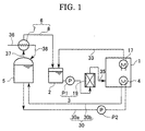
- FIG. 1 is a structural diagram illustrating a first embodiment of a fuel cell power generating system according to the invention;
- FIG. 2 is a structural diagram showing a fuel cell unit in the fuel cell power generating system shown in FIG. 1;
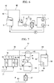
- FIG. 3 is a structural diagram illustrating a second embodiment of the fuel cell power generating system according to the invention;
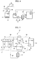
- FIG. 4 is a structural diagram illustrating a third embodiment of the fuel cell power generating system according to the invention;
- FIG. 5 is a structural diagram illustrating a fourth embodiment of the fuel cell power generating system according to the invention;
- FIG. 6 is a structural diagram exemplifying a conventional fuel cell power generating system; and
- FIG. 7 is a structural diagram exemplifying another conventional fuel cell power generating system.
- FIGS. 1 and 2 illustrate a first embodiment of a fuel cell power generating system according to the invention. The fuel cell power generating system comprises a
fuel cell unit 1, awater storage tank 2 for supply water to serve as coolant for thefuel cell unit 1, awater treatment system 3 which performs purification of the supply water in thewater storage tank 2 and supplies the resultant water as coolant to thefuel cell unit 1, aheat exchanger 4 for recovering the exhaust heat as heating means which heats up water using the exhaust heat from thefuel cell unit 1, a hotwater storage tank 5 which retains hot water obtained by using theheat exchanger 4, and a condensed-water supply system 6 which supplies thewater storage tank 2 with condensed water obtained by condensing steam from the hot water in the hotwater storage tank 5. - As shown in FIG. 2, the
fuel cell unit 1 essentially comprises afuel cell stack 11, areformer 12 which reforms fuel with steam, acoolant circulation path 13 where the coolant that cools thefuel cell stack 11 circulates, asteam separator 14 as a source to supply steam which is used by thereformer 12, aheat exchanger 15 which cools the coolant, acirculation path 16 where intrasystem water whose heat is exchanged with the heat of the coolant in theheat exchanger 15, and aheat exchanger 17 for recovering the condensed water in the exhaust gas which condenses steam in the exhaust gas discharged from thefuel cell unit 1 and recovers the condensed water. - The
fuel cell stack 11 is so constructed as to have aanode 21 and ancathode 22 sandwiching anelectrolyte 23.Electrode plates anode 21 and theelectrolyte 23 and between thecathode 22 and theelectrolyte 23. - The
steam separator 14, provided in thecoolant circulation path 13, can separate steam from the coolant. - The
reformer 12 can reform fuel supplied through afuel supply path 26 with steam supplied from thesteam separator 14 through asteam supply path 27, thereby producing a fuel gas containing hydrogen. - The
heat exchanger 17, which is provided in the intrasystemwater circulation path 16, can condense steam in the exhaust gas discharged throughexhaust paths reformer 12 and thecathode 22 by cooling the steam with the intrasystem water and recover the condensed water. - As shown in FIG. 1, the
water treatment system 3 has awater purifying equipment 19 and a water feed pump P1. - A purifying equipment which eliminates an impurity such as ions or a solid material is used as the
water purifying equipment 19. For example, an ion-exchange demineralizer using ion-exchanging resins, a demineralizer using a reverse osmosis membrane, and a equipment using an ultrafiltration membrane can be used as thewater purifying equipment 19. - As shown in FIGS. 1 and 2, the
heat exchanger 4 for recovering the exhaust heat, which is provided in the intrasystemwater circulation path 16, can heat up water supplied from the hotwater storage tank 5 through asupply path 30a of a hotwater circulation path 30 using the intrasystem water. - The hot
water storage tank 5 is designed to be able to feed hot water in the tank to heat using equipment (not shown). - As shown in FIG. 1, auxiliary
water supply path 36 which supplies auxiliary water is connected to the hotwater storage tank 5. When the amount of water in the hotwater storage tank 5 becomes insufficient due to the supply of hot water to the heat using equipment (not illustrated), auxiliary water can be supplied into the hotwater storage tank 5. - The condensed-
water supply system 6 has a heat exchanger 7 for recovering the condensed water which condenses and recovers steam from the hot water in the hotwater storage tank 5, and a condensed-water supply path 8 which supplies the condensed water recovered by the heat exchanger 7 to thewater storage tank 2. - The heat exchanger 7 is provided in the auxiliary
water supply path 36 which supplies auxiliary water into the hotwater storage tank 5. The heat exchanger 7 can condense steam in the gas in the hotwater storage tank 5, which is led out through anoutlet path 37 connected at the upper portion of thetank 5, with auxiliary water which flows in the auxiliarywater supply path 36, and recover the resultant water as condensed water. - The following will discuss how to use the fuel cell power generating system.
- As shown in FIG. 2, the fuel cell power generating system feeds fuel, such as a desulfurated natural gas or naphtha to the
reformer 12 through thefuel supply path 26, and reforms the fuel with steam supplied from thesteam separator 14 through thesteam supply path 27, thereby generating a hydrogen-contained fuel gas. - The fuel gas is supplied to the
anode 21 of thefuel cell stack 11 via a carbon monoxide conversion unit or the like (not shown) through a fuel-gas supply path 31 and an oxidizing gas such as air is supplied to thecathode 22 through an oxidizing-gas supply path 32. The fuel gas reacts with the oxidizing gas electrochemically, thus generating power. - The fuel-based exhaust gas from the
reformer 12 is discharged outside the system via theheat exchanger 17 through theexhaust path 28. The oxidant-based exhaust gas from thecathode 22 merges with the fuel-based exhaust gas in theexhaust path 28 through theexhaust path 29 and is discharged outside the system via theheat exchanger 17. - As the coolant circulates in the
coolant circulation path 13, thefuel cell stack 11 is cooled to maintain a predetermined temperature. At this time, the coolant is heated to a high temperature and is led into thesteam separator 14. - The
steam separator 14 separates steam from the coolant and feeds part of the steam to thereformer 12 through thesteam supply path 27. - The coolant that has passed through the
steam separator 14 is cooled down in theheat exchanger 15 through heat exchange with the intrasystem water that flows in the intrasystemwater circulation path 16, and is then supplied to thefuel cell stack 11 again. Thereafter, the circulation process is repeated. - The intrasystem water flowing in the intrasystem
water circulation path 16 cools the coolant in theheat exchanger 15 and cools the fuel-based exhaust gas and oxidant-based exhaust gas in theexhaust path 28, thus condensing the steam in the exhaust gas. - The condensed water that has been recovered by the
heat exchanger 17 is fed to thewater storage tank 2 through a condensed-water recovery path 33. - In the
heat exchanger 4, the intrasystem water heated by theheat exchangers water storage tank 5 with a water feed pump P2 through thesupply path 30a. The heated hot water is supplied through areturn path 30b to the hotwater storage tank 5. - In short, the
heat exchanger 4 heats up water with the intrasystem water, heated by the coolant that has become hot with the heat (exhaust heat) generated when thefuel cell stack 11 generates power. - When the amount of water in the hot
water storage tank 5 becomes insufficient due to the supply of hot water to the unillustrated heat using equipment, auxiliary water, such as city water, is supplied to the hotwater storage tank 5 through the auxiliarywater supply path 36. - Part of the coolant flowing in the
coolant circulation path 13 is separated as steam by thesteam separator 14 and is led out from thecoolant circulation path 13 through thesteam supply path 27. It is therefore necessary to supplement insufficient coolant. - Accordingly, the supply water in the
water storage tank 2 is supplied to thewater purifying equipment 19 using the water feed pump P1, impurities are removed from the supply water there, and the resultant purified water is supplied as coolant to thecoolant circulation path 13 through acoolant supply path 35. - According to the fuel cell power generating system of the embodiment, when the supplement of the coolant reduces the amount of water in the
water storage tank 2, supplementary water is provided into thewater storage tank 2 as follows by using the condensed-water supply system 6. - As the water in the hot
water storage tank 5 is hot, the vapor pressure in the hotwater storage tank 5 is high and the gas in the hotwater storage tank 5 that is led out through theoutlet path 37 contains a lot of steam. - As the steam-containing gas is led to the heat exchanger 7 through the
outlet path 37, the steam in the gas is cooled and condensed by the auxiliary water (city water or the like) that flows in the auxiliarywater supply path 36. - The condensed water is supplied as auxiliary water to the
water storage tank 2 through the condensed-water supply path 8. As the condensed water is distilled water whose impurities such as ions have a very low concentration, the amount of the impurities fed into thewater storage tank 2 are minimized and the concentration of the impurities in thewater storage tank 2 become lower. This reduces a load of demineralization or the like applied to thewater purifying equipment 19. - It is therefore possible to set the capacity of the
water purifying equipment 19 low. This can contribute to reducing the equipment cost needed for thewater treatment system 3 and suppressing the operation cost, such as the cost of recycling the ion exchange resin, low. - Reducing the required capacity of the
water purifying equipment 19 allows designing smaller theequipment 19, thus decreasing the space for this equipment. - As the
heat exchanger 4 is designed in such a way as to heat up water using, as exhaust heat, the heat generated when thefuel cell unit 1 generates power, hot water can be provided by effectively using the exhaust heat. This can improve the energy efficiency. - The heat exchanger 7 is so constructed as to be able to condense steam in the gas in the hot
water storage tank 5 by cooling the steam with the auxiliary water flowing in the auxiliarywater supply path 36. This structure eliminates the need for a separate cooling medium while condensing steam in the condensed-water supply system 6, thus leading to a further reduction in operation cost. - FIG. 3 illustrates a second embodiment of the fuel cell power generating system according to the invention, which has a
partition 20 provided in the hotwater storage tank 5 to separate the interior of thetank 5 into two rooms or upper andlower rooms - The
partition 20 serves to keep the temperature of the hot water in theupper room 5a high to increase the amount of steam to be led into the heat exchanger 7. Thepartition 20 has aventilation port 20a which permits ventilation of hot water between theupper room 5a and thelower room 5b. - The inside diameter of the
ventilation port 20a is so set as to restrict the flow of water in thelower room 5b into theupper room 5a. - The
partition 20 can be formed of a metal, such as stainless steel, or a synthetic resin, such as polyvinyl chloride. Particularly, it is preferable to use a synthetic resin which has an excellent heat insulating property. - A
supply path 40a and returnpath 40b of a hotwater circulation path 40 are respectively connected to the lower portion and upper portion of the hotwater storage tank 5, so that after the water heated by theheat exchanger 4 is led into theupper room 5a through thereturn path 40b, the water flows to thelower room 5b via theventilation port 20a and flows into thesupply path 40a from thelower room 5b. - A auxiliary
water supply path 38 which feeds auxiliary water into thelower room 5b is connected to the lower portion of the hotwater storage tank 5, so that when the amount of water in the hotwater storage tank 5 becomes insufficient due to the supply of hot water to a heat using equipment (not shown), auxiliary water can be supplied into thelower room 5b. - In the fuel cell power generating system, high-temperature hot water that has been heated by the
heat exchanger 4 and is returned to the hotwater storage tank 5 through thereturn path 40b is led into theupper room 5a located above thepartition 20. - The steam that is originated from the vaporization of the high-temperature hot water led into the
upper room 5a is supplied to the heat exchanger 7 through theoutlet path 37. - The hot water in the
upper room 5a flows into thelower room 5b from theventilation port 20a according to the circulation flow in the hotwater circulation path 40, and flows to theheat exchanger 4 through thesupply path 40a. - The hot water in the
storage tank 5 is cooled by the outside air so that its temperature gradually falls. Because theupper room 5a corresponds to the upstream side of the flow of the hot water in the hotwater storage tank 5 and thepartition 20 prevents the flow of the hot water into theupper room 5a from thelower room 5b, however, the temperature of the hot water in theupper room 5a is kept relatively high. - The fuel cell power generating system of the second embodiment, like the fuel cell power generating system of the first embodiment, can reduce the concentration of impurities in the supply water to be supplied to the water purified
equipment 19, thus reducing the load applied to the water purifiedequipment 19, and allowing the equipment to be made smaller, thus lowering the equipment cost and the operation cost. - According to the embodiment, the provision of the
partition 20 that defines the upper andlower rooms water storage tank 5 can prevent hot water of a relatively low temperature in thelower room 5b from being mixed with hot water of a high temperature in theupper room 5a. It is therefore possible to keep the temperature of the hot water in theupper room 5a high and increase the vapor pressure in theupper room 5a. - This can increase the steam content in the gas that is led into the heat exchanger 7, thus improving the efficiency of recovering the condensed water in the heat exchanger 7.
- It is therefore possible to increase the supply amount of the condensed water or distilled water having a low impurity concentration to the
water storage tank 2, thus lowering the impurity concentration in thewater storage tank 2 and reducing the load of demineralization or the like applied to thewater purifying equipment 19. - This can allow the capacity of the
water purifying equipment 19 to be set low, thus leading to lower equipment and operation costs. - Although the
heat exchanger 4 which uses the exhaust heat from thefuel cell unit 1 is provided as a heating means in the fuel cell power generating system of the embodiment, the heating means that heats up water to be supplied to a heat using equipment is not limited to the type which uses the exhaust heat from thefuel cell unit 1. - As shown in FIG. 4, for example, a
heater 41 which heats up water in thestorage tank 5 may be provided in thetank 5 in place of theheat exchanger 4. - Although the illustrated fuel cell power generating system of the embodiment has the structure that uses supply water recovered by the
heat exchanger 17 as coolant, the fuel cell power generating system of the invention is not limited to this type but may have a structure that does not recover steam in the exhaust gas and uses condensed water from condensed-water supply system 6 or auxiliary water, such as city water, as supply water. - Because the fuel cell power generating system of the invention can maintain the impurity concentration in the supply water to be supplied to the water treatment system at a low level, the water treatment system may be eliminated.
- Further, the coolant circulation path may be designed in such a way that the coolant is led into the
water storage tank 2 through the condensed-water recovery path 33 after passing thefuel cell stack 11 and thesteam separator 14. - FIG. 5 illustrates a fourth embodiment of the fuel cell power generating system according to the invention. The fuel cell power generating system comprises a fuel cell
power generating equipment 51 which generates power by reacting the fuel gas with an oxidizing gas electrochemically, a hotwater storage tank 52 which retains hot water heated by using the heat produced while generating power, and a auxiliarywater supply path 59 which supplies auxiliary water, such as city water, to the hotwater storage tank 52. - The fuel cell
power generating equipment 51 has afuel cell stack 53, acoolant circulation path 54 which regulates the temperature of thefuel cell stack 53, aheat exchanger 55 for recovering water which condenses and recovers steam in the exhaust gas discharged from thefuel cell stack 53, awater storage tank 56 which retains supply water recovered by theheat exchanger 55, awater purifying equipment 57 which purifies the supply water in thewater storage tank 56 and supplies the purified water as coolant to thecoolant circulation path 54, anheat exchanger 58 as heating means which heats water using the coolant to provide hot water, and a auxiliarywater supply path 60 which feeds auxiliary water, such as city water, to thewater storage tank 56. - The
fuel cell stack 53 is so constructed as to have aanode 71 and ancathode 72 sandwiching anelectrolyte 73.Electrode plates anode 71 and theelectrolyte 73 and between thecathode 72 and theelectrolyte 73. - An ion-exchange demineralizer or the like, which removes an impurity from the supply water from the
water storage tank 56, is used as thewater purifying equipment 57. - The hot
water storage tank 52 can supply hot water in the tank to heat using equipment (not shown). - In the fuel cell power generating system of the embodiment, the
heat exchanger 55 is provided in the auxiliarywater supply path 59 and can condense steam in the exhaust gas discharged from theanode 71 and thecathode 72 throughexhaust paths - The following will discuss how to use the fuel cell power generating system.
- In the fuel cell power generating system, a reformer (not shown) reforms fuel such as a natural gas to steam, thus generating a fuel gas containing a hydrogen gas, the fuel gas is supplied to the
anode 71 through a fuel-gas supply path 76, an oxidizing gas such as air is supplied to thecathode 72 through an oxidizing-gas supply path 77, and the fuel gas reacts with oxidizing gas electrochemically, thereby generating power. - The fuel-based exhaust gas from the reformer is discharged outside the system via the
heat exchanger 55 through theexhaust path 78. The oxidant-based exhaust gas from thecathode 72 merges with the fuel-based exhaust gas in theexhaust path 78 through theexhaust path 79 and is discharged outside the system via theheat exchanger 55. - As the coolant circulates in the
coolant circulation path 54, thefuel cell stack 53 is cooled down to maintain a predetermined temperature. At this time, the coolant is heated to a high temperature (normally 60 to 80°C) and is led into theheat exchanger 58. - In the
heat exchanger 58, the water in the hotwater storage tank 52 is heated to become hot water of about 50 to 60°C by the high-temperature coolant whose temperature in turn falls to about 50 to 60°C. - The coolant that has passed the
heat exchanger 58 is fed through apath 68 to thewater storage tank 56. - When the amount of water in the
water storage tank 56 becomes insufficient, auxiliary water, such as city water, is supplied to thewater storage tank 56 through the auxiliarywater supply path 60. - When the amount of water in the hot
water storage tank 52 becomes insufficient due to the supply of hot water to the heat using equipment (not shown), auxiliary water, such as city water, is supplied to the hotwater storage tank 52 through the auxiliarywater supply path 59. The temperature of the city water is normally 5 to 25°C. - In the
heat exchanger 55, steam in the fuel-based exhaust gas and oxidant-based exhaust gas in theexhaust path 78 is cooled down with the auxiliary water flowing in the auxiliarywater supply path 59 to be condensed and the condensed water is recovered into thewater storage tank 56 through apath 62. - As an impurity, such as carbonate ions or metal ions, originated from auxiliary water, such as city water, is mixed in supply water in the
water storage tank 56, the supply water is supplied through apath 80 to thewater purifying equipment 57 to remove its impurities and is then connected to thecoolant circulation path 54 in thefuel cell stack 53 as coolant through asupply path 63. - The fuel cell power generating system of the embodiment has the
heat exchanger 55 provided in the auxiliarywater supply path 59 so that steam in the exhaust gas discharged through theexhaust paths water supply path 59. Therefore, this system can condense steam using low-temperature auxiliary water, as compared with a fuel cell power generating system (see FIG. 7) which can condense steam in the exhaust gas with coolant whose temperature becomes relatively high. - It is therefore possible to improve the efficiency of cooling steam in the exhaust gas to thereby increase the recovery amount of condensed water, which is distilled water whose impurities such as ions have a low concentration.
- This structure can lower the impurity concentration in the
water storage tank 56, thus reducing the load of demineralization or the like applied to thewater purifying equipment 57. - It is therefore possible to set the demanded capacity of the
water purifying equipment 57 low, thus reducing the equipment cost needed for thewater purifying equipment 57 and restrain operation costs, such as the regenerating cost for an ion exchange resin. - As the capacity of the
water purifying equipment 57 can be set low, the equipment can be made smaller, thus reducing the required space for the equipment. - Because the recovery amount of condensed water can be increased, it is possible to reduce the amount of auxiliary water to be supplied to the
water storage tank 56 through the auxiliarywater supply path 60. This can lead to a reduction in the cost that is needed for the auxiliary water.
Claims (7)
- A fuel cell power generating system comprising:a fuel cell unit (1) having a coolant circulation system (13);a water storage tank (2) for supply water to serve as coolant for said fuel cell unit (1);a water treatment system (3) for purifying said supply water in said water storage tank (2) and supplying said purified supply water as coolant to said fuel cell unit (1);heating means (4) for heating water;a hot water storage tank (5) for hot water acquired by said heating means (4); anda condensed-water supply system (6) for supplying said water storage tank (2) with condensed water obtained by condensing steam from said hot water in said hot water storage tank (5).
- The fuel cell power generating system according to claim 1, wherein said heating means (4) is constructed in such a way as to be able to heat water by using heat generated when said fuel cell unit (1) generates power.
- The fuel cell power generating system according to claim 1, wherein said condensed-water supply system (6) has a heat exchanger (7) for condensing steam from said hot water in said hot water storage tank (5) by cooling that steam with auxiliary water to be supplied to said hot water storage tank (5) and recovering said condensed water, and a condensed-water supply path (8) for supplying said condensed water recovered by said heat exchanger (7) to said water storage tank (2).
- The fuel cell power generating system according to any one of claims 1 to 3, wherein said hot water storage tank (5) is provided inside with a partition (20) for defining a plurality of rooms in said hot water storage tank (5) in such a way that said hot water heated by said heating means (4) is led into one of said rooms (5a) and steam from said hot water in that room (5a) is supplied to said condensed-water supply system (6).
- A method of operating a fuel cell power generating system comprising a fuel cell unit (1) having a coolant circulation system (13), a water storage tank (2) for supply water to serve as coolant for said fuel cell unit (1), a water treatment system (3) for purifying said supply water in said water storage tank (2) and supplying said purified supply water as coolant to said fuel cell unit (1), heating means (4) for heating water, and a hot water storage tank (5) for hot water acquired by said heating means (4), said method comprising the step of:
supplying said water storage tank (2) with condensed water obtaining by condensing steam from said hot water in said hot water storage tank (5). - A fuel cell power generating system comprising:a fuel cell power generating equipment (51) for generating power by reacting the fuel gas containing a hydrogen gas with an oxidizing gas electrochemically,a hot water storage tank (52) for hot water heated by heat generated while power is generated by said fuel cell power generating equipment (51); anda auxiliary water supply path (59) for supplying auxiliary water to said hot water storage tank (52),said fuel cell power generating equipment (51) having a fuel cell stack (53), a coolant circulation path (54) for regulating a temperature of said fuel cell stack (53), a heat exchanger (55) for condensing steam in an exhaust gas discharged from said fuel cell stack (53) and recovering said condensed water, water purifying equipment (57) for purifying water recovered by said heat exchanger (55) and supplying said purified water as coolant to said coolant circulation path (54), and heating means (58) for heating water to provide hot water using said coolant,whereby said heat exchanger (55) condenses said steam in said exhaust gas by cooling said steam with said auxiliary water flowing in said auxiliary water supply path (59).
- A method of operating a fuel cell power generating system comprising a fuel cell power generating equipment (51) for generating power by reacting the fuel gas containing a hydrogen gas with an oxidizing gas by electrochemical reaction, a hot water storage tank (52) for hot water heated by heat generated while power is generated by said fuel cell power generating equipment (51), and a auxiliary water supply path (59) for supplying auxiliary water to said hot water storage tank (52), whereinsaid fuel cell power generating equipment (51) has a fuel cell stack (53), a coolant circulation path (54) for regulating a temperature of said fuel cell stack (53), a heat exchanger (55) for condensing steam in an exhaust gas discharged from said fuel cell stack (53) and recovering said condensed water, water purifying equipment (57) for purifying water recovered by said heat exchanger (55) and supplying said purified water as coolant to said coolant circulation path (54), and heating means (58) for heating water to provide hot water using said coolant, andsaid heat exchanger (55) condenses said steam in said exhaust gas by cooling said steam with said auxiliary water flowing in said auxiliary water supply path (59).
Priority Applications (1)
| Application Number | Priority Date | Filing Date | Title |
|---|---|---|---|
| EP08101770A EP1968145A1 (en) | 2000-06-20 | 2001-06-19 | Fuel cell power generating system and operation method |
Applications Claiming Priority (4)
| Application Number | Priority Date | Filing Date | Title |
|---|---|---|---|
| JP2000185356 | 2000-06-20 | ||
| JP2000185356A JP4660889B2 (en) | 2000-06-20 | 2000-06-20 | Fuel cell power generation system and operation method thereof |
| JP2000185355 | 2000-06-20 | ||
| JP2000185355A JP4660888B2 (en) | 2000-06-20 | 2000-06-20 | Fuel cell power generation system and operation method thereof |
Related Child Applications (1)
| Application Number | Title | Priority Date | Filing Date |
|---|---|---|---|
| EP08101770A Division EP1968145A1 (en) | 2000-06-20 | 2001-06-19 | Fuel cell power generating system and operation method |
Publications (3)
| Publication Number | Publication Date |
|---|---|
| EP1168476A2 true EP1168476A2 (en) | 2002-01-02 |
| EP1168476A3 EP1168476A3 (en) | 2006-06-07 |
| EP1168476B1 EP1168476B1 (en) | 2009-04-15 |
Family
ID=26594317
Family Applications (2)
| Application Number | Title | Priority Date | Filing Date |
|---|---|---|---|
| EP08101770A Withdrawn EP1968145A1 (en) | 2000-06-20 | 2001-06-19 | Fuel cell power generating system and operation method |
| EP01401611A Expired - Lifetime EP1168476B1 (en) | 2000-06-20 | 2001-06-19 | Fuel cell power generating system and operation method |
Family Applications Before (1)
| Application Number | Title | Priority Date | Filing Date |
|---|---|---|---|
| EP08101770A Withdrawn EP1968145A1 (en) | 2000-06-20 | 2001-06-19 | Fuel cell power generating system and operation method |
Country Status (5)
| Country | Link |
|---|---|
| US (1) | US6787255B2 (en) |
| EP (2) | EP1968145A1 (en) |
| AT (1) | ATE429043T1 (en) |
| DE (1) | DE60138338D1 (en) |
| ES (1) | ES2325978T3 (en) |
Cited By (1)
| Publication number | Priority date | Publication date | Assignee | Title |
|---|---|---|---|---|
| GB2396688A (en) * | 2002-11-22 | 2004-06-30 | Intelligent Energy Ltd | Thermal energy management in electrochemical fuel cells |
Families Citing this family (10)
| Publication number | Priority date | Publication date | Assignee | Title |
|---|---|---|---|---|
| DE10104246C1 (en) * | 2001-01-31 | 2002-06-06 | Zsw | Fuel cell e.g. for electric traction drive, incorporates dampening of process gas used for operation of fuel cell |
| WO2004092054A2 (en) * | 2002-08-13 | 2004-10-28 | Enersol Inc., N.A., L.P. | Hydrogen odorants and odorant selection method |
| JP4066361B2 (en) * | 2003-07-30 | 2008-03-26 | トヨタ自動車株式会社 | Fuel cell cooling system |
| CN1993854A (en) * | 2004-09-27 | 2007-07-04 | 松下电器产业株式会社 | Fuel cell system and method for operating fuel cell system |
| US20060141329A1 (en) * | 2004-12-28 | 2006-06-29 | Utc Fuel Cells, Llc | Fuel cell demineralizers integrated with coolant accumulator |
| US8227120B2 (en) * | 2007-07-20 | 2012-07-24 | Utc Power Corporation | Volatile organic compound abatement with fuel cell power plant |
| US8951696B2 (en) * | 2008-03-28 | 2015-02-10 | Jx Nippon Oil & Energy Corporation | Fuel electrode catalyst for fuel cell, electrode/membrane assembly, and fuel cell and fuel cell system provided with the electrode/membrane assembly |
| DE102008030567A1 (en) * | 2008-06-27 | 2009-12-31 | Bayerische Motoren Werke Aktiengesellschaft | A fuel cell assembly having storage means for storing and providing liquid coolant |
| US10173389B2 (en) * | 2015-12-15 | 2019-01-08 | Bloom Energy Corporation | Carbon dioxide shielded natural gas line and method of using thereof |
| JP6508123B2 (en) * | 2016-05-13 | 2019-05-08 | 信越半導体株式会社 | Method of sorting template assembly, method of polishing workpiece and template assembly |
Citations (4)
| Publication number | Priority date | Publication date | Assignee | Title |
|---|---|---|---|---|
| US5268240A (en) * | 1991-07-17 | 1993-12-07 | Fuji Electric Co., Ltd. | Unit system-assembled fuel cell power generation system |
| US5335628A (en) * | 1993-09-03 | 1994-08-09 | Aqua-Chem, Inc. | Integrated boiler/fuel cell system |
| US5985474A (en) * | 1998-08-26 | 1999-11-16 | Plug Power, L.L.C. | Integrated full processor, furnace, and fuel cell system for providing heat and electrical power to a building |
| EP1056148A2 (en) * | 1999-05-25 | 2000-11-29 | Matsushita Electric Industrial Co., Ltd. | Solid polymer electrolyte fuel cell cogeneration system |
Family Cites Families (8)
| Publication number | Priority date | Publication date | Assignee | Title |
|---|---|---|---|---|
| US4120787A (en) * | 1976-12-29 | 1978-10-17 | United Technologies Corporation | Fuel cell water conditioning process and system and deaerator for use therein |
| US4973529A (en) * | 1985-06-18 | 1990-11-27 | International Fuel Cells | Apparatus and process for forming an aqueous solution |
| US5773162A (en) * | 1993-10-12 | 1998-06-30 | California Institute Of Technology | Direct methanol feed fuel cell and system |
| US6376113B1 (en) * | 1998-11-12 | 2002-04-23 | Idatech, Llc | Integrated fuel cell system |
| JPH11317236A (en) * | 1997-12-22 | 1999-11-16 | Aqueous Reserch:Kk | Fuel cell system |
| JP2000185356A (en) | 1998-12-22 | 2000-07-04 | Toyoda Gosei Co Ltd | Dichroic skin automobile interior decorative article |
| JP2000185355A (en) | 1998-12-24 | 2000-07-04 | Toyota Motor Corp | Method and apparatus for manufacturing foamed molded product |
| US6171718B1 (en) * | 1998-12-28 | 2001-01-09 | International Fuel Cells, Llc | Pressurized water recovery system for a fuel cell power plant |
-
2001
- 2001-06-19 EP EP08101770A patent/EP1968145A1/en not_active Withdrawn
- 2001-06-19 ES ES01401611T patent/ES2325978T3/en not_active Expired - Lifetime
- 2001-06-19 EP EP01401611A patent/EP1168476B1/en not_active Expired - Lifetime
- 2001-06-19 AT AT01401611T patent/ATE429043T1/en not_active IP Right Cessation
- 2001-06-19 DE DE60138338T patent/DE60138338D1/en not_active Expired - Lifetime
- 2001-06-20 US US09/885,672 patent/US6787255B2/en not_active Expired - Fee Related
Patent Citations (4)
| Publication number | Priority date | Publication date | Assignee | Title |
|---|---|---|---|---|
| US5268240A (en) * | 1991-07-17 | 1993-12-07 | Fuji Electric Co., Ltd. | Unit system-assembled fuel cell power generation system |
| US5335628A (en) * | 1993-09-03 | 1994-08-09 | Aqua-Chem, Inc. | Integrated boiler/fuel cell system |
| US5985474A (en) * | 1998-08-26 | 1999-11-16 | Plug Power, L.L.C. | Integrated full processor, furnace, and fuel cell system for providing heat and electrical power to a building |
| EP1056148A2 (en) * | 1999-05-25 | 2000-11-29 | Matsushita Electric Industrial Co., Ltd. | Solid polymer electrolyte fuel cell cogeneration system |
Cited By (3)
| Publication number | Priority date | Publication date | Assignee | Title |
|---|---|---|---|---|
| GB2396688A (en) * | 2002-11-22 | 2004-06-30 | Intelligent Energy Ltd | Thermal energy management in electrochemical fuel cells |
| GB2396688B (en) * | 2002-11-22 | 2006-06-28 | Intelligent Energy Ltd | Thermal energy management in electrochemical fuel cells |
| US7498094B2 (en) | 2002-11-22 | 2009-03-03 | Intelligent Energy Limited | Thermal energy management in electrochemical fuel cells |
Also Published As
| Publication number | Publication date |
|---|---|
| DE60138338D1 (en) | 2009-05-28 |
| ATE429043T1 (en) | 2009-05-15 |
| ES2325978T3 (en) | 2009-09-28 |
| US20010053470A1 (en) | 2001-12-20 |
| EP1168476A3 (en) | 2006-06-07 |
| US6787255B2 (en) | 2004-09-07 |
| EP1168476B1 (en) | 2009-04-15 |
| EP1968145A1 (en) | 2008-09-10 |
Similar Documents
| Publication | Publication Date | Title |
|---|---|---|
| US7507487B2 (en) | Solid polymer fuel cell with reactant air humidified by a processed water tank | |
| JP2002525805A (en) | Fuel cell power supply with exhaust recovery for improved water management | |
| WO2000063994A1 (en) | Water treatment system for a fuel cell assembly | |
| EP1168476B1 (en) | Fuel cell power generating system and operation method | |
| JP4624670B2 (en) | Integration of the functions of many components of a fuel cell power plant | |
| US6692854B2 (en) | Fuel cell generator system and method for operating same | |
| JP2010238485A (en) | Fuel cell generator, and operation method of fuel cell generator | |
| JP2008234869A (en) | Fuel cell system | |
| KR20030073679A (en) | Cooling water recycling system for fuel cell | |
| US20030148157A1 (en) | Functional integration of multiple components for a fuel cell power plant | |
| JP6629167B2 (en) | Recirculating fuel cell system | |
| JP2009224121A (en) | Fuel cell power generation device | |
| JP4719407B2 (en) | Fuel cell cogeneration system | |
| JP5286851B2 (en) | Fuel cell power generator | |
| JP4660888B2 (en) | Fuel cell power generation system and operation method thereof | |
| JP5292865B2 (en) | Water recovery method for fuel cell power generator and fuel cell power generator | |
| JP2001035520A (en) | Waste heat recovering apparatus for fuel cell generating apparatus | |
| JP2002298894A (en) | Water treatment system for solid polymer fuel cell generator set | |
| JP2002008690A (en) | Fuel cell power generation system and its running method | |
| JP2003249255A (en) | Fuel cell system | |
| JP2007250447A (en) | Water treatment device in fuel cell system | |
| JP5380868B2 (en) | Condensed water decay prevention method and fuel cell power generator | |
| KR100550954B1 (en) | fuel cell system | |
| JP2007018859A (en) | Fuel cell power generation system | |
| JP2009140726A (en) | Fuel cell power generation device |
Legal Events
| Date | Code | Title | Description |
|---|---|---|---|
| PUAI | Public reference made under article 153(3) epc to a published international application that has entered the european phase |
Free format text: ORIGINAL CODE: 0009012 |
|
| AK | Designated contracting states |
Kind code of ref document: A2 Designated state(s): AT BE CH CY DE DK ES FI FR GB GR IE IT LI LU MC NL PT SE TR |
|
| AX | Request for extension of the european patent |
Free format text: AL;LT;LV;MK;RO;SI |
|
| PUAL | Search report despatched |
Free format text: ORIGINAL CODE: 0009013 |
|
| AK | Designated contracting states |
Kind code of ref document: A3 Designated state(s): AT BE CH CY DE DK ES FI FR GB GR IE IT LI LU MC NL PT SE TR |
|
| AX | Request for extension of the european patent |
Extension state: AL LT LV MK RO SI |
|
| 17P | Request for examination filed |
Effective date: 20061122 |
|
| AKX | Designation fees paid |
Designated state(s): AT BE CH CY DE DK ES FI FR GB GR IE IT LI LU MC NL PT SE TR |
|
| 17Q | First examination report despatched |
Effective date: 20071011 |
|
| GRAP | Despatch of communication of intention to grant a patent |
Free format text: ORIGINAL CODE: EPIDOSNIGR1 |
|
| GRAJ | Information related to disapproval of communication of intention to grant by the applicant or resumption of examination proceedings by the epo deleted |
Free format text: ORIGINAL CODE: EPIDOSDIGR1 |
|
| GRAP | Despatch of communication of intention to grant a patent |
Free format text: ORIGINAL CODE: EPIDOSNIGR1 |
|
| GRAS | Grant fee paid |
Free format text: ORIGINAL CODE: EPIDOSNIGR3 |
|
| GRAA | (expected) grant |
Free format text: ORIGINAL CODE: 0009210 |
|
| RIN1 | Information on inventor provided before grant (corrected) |
Inventor name: MISUMI, YOSHITERU C/O KURITA WATER INDUSTRIES, LTD |
|
| AK | Designated contracting states |
Kind code of ref document: B1 Designated state(s): AT BE CH CY DE DK ES FI FR GB GR IE IT LI LU MC NL PT SE TR |
|
| REG | Reference to a national code |
Ref country code: GB Ref legal event code: FG4D Ref country code: CH Ref legal event code: EP |
|
| REG | Reference to a national code |
Ref country code: IE Ref legal event code: FG4D |
|
| REF | Corresponds to: |
Ref document number: 60138338 Country of ref document: DE Date of ref document: 20090528 Kind code of ref document: P |
|
| REG | Reference to a national code |
Ref country code: ES Ref legal event code: FG2A Ref document number: 2325978 Country of ref document: ES Kind code of ref document: T3 |
|
| PG25 | Lapsed in a contracting state [announced via postgrant information from national office to epo] |
Ref country code: PT Free format text: LAPSE BECAUSE OF FAILURE TO SUBMIT A TRANSLATION OF THE DESCRIPTION OR TO PAY THE FEE WITHIN THE PRESCRIBED TIME-LIMIT Effective date: 20090915 Ref country code: AT Free format text: LAPSE BECAUSE OF FAILURE TO SUBMIT A TRANSLATION OF THE DESCRIPTION OR TO PAY THE FEE WITHIN THE PRESCRIBED TIME-LIMIT Effective date: 20090415 Ref country code: FI Free format text: LAPSE BECAUSE OF FAILURE TO SUBMIT A TRANSLATION OF THE DESCRIPTION OR TO PAY THE FEE WITHIN THE PRESCRIBED TIME-LIMIT Effective date: 20090415 |
|
| PG25 | Lapsed in a contracting state [announced via postgrant information from national office to epo] |
Ref country code: SE Free format text: LAPSE BECAUSE OF FAILURE TO SUBMIT A TRANSLATION OF THE DESCRIPTION OR TO PAY THE FEE WITHIN THE PRESCRIBED TIME-LIMIT Effective date: 20090715 |
|
| PG25 | Lapsed in a contracting state [announced via postgrant information from national office to epo] |
Ref country code: DK Free format text: LAPSE BECAUSE OF FAILURE TO SUBMIT A TRANSLATION OF THE DESCRIPTION OR TO PAY THE FEE WITHIN THE PRESCRIBED TIME-LIMIT Effective date: 20090415 Ref country code: MC Free format text: LAPSE BECAUSE OF NON-PAYMENT OF DUE FEES Effective date: 20090630 |
|
| REG | Reference to a national code |
Ref country code: CH Ref legal event code: PL |
|
| PLBE | No opposition filed within time limit |
Free format text: ORIGINAL CODE: 0009261 |
|
| STAA | Information on the status of an ep patent application or granted ep patent |
Free format text: STATUS: NO OPPOSITION FILED WITHIN TIME LIMIT |
|
| 26N | No opposition filed |
Effective date: 20100118 |
|
| PG25 | Lapsed in a contracting state [announced via postgrant information from national office to epo] |
Ref country code: LI Free format text: LAPSE BECAUSE OF NON-PAYMENT OF DUE FEES Effective date: 20090630 Ref country code: IE Free format text: LAPSE BECAUSE OF NON-PAYMENT OF DUE FEES Effective date: 20090619 Ref country code: CH Free format text: LAPSE BECAUSE OF NON-PAYMENT OF DUE FEES Effective date: 20090630 |
|
| PG25 | Lapsed in a contracting state [announced via postgrant information from national office to epo] |
Ref country code: GR Free format text: LAPSE BECAUSE OF FAILURE TO SUBMIT A TRANSLATION OF THE DESCRIPTION OR TO PAY THE FEE WITHIN THE PRESCRIBED TIME-LIMIT Effective date: 20090716 |
|
| PG25 | Lapsed in a contracting state [announced via postgrant information from national office to epo] |
Ref country code: LU Free format text: LAPSE BECAUSE OF NON-PAYMENT OF DUE FEES Effective date: 20090619 |
|
| PG25 | Lapsed in a contracting state [announced via postgrant information from national office to epo] |
Ref country code: TR Free format text: LAPSE BECAUSE OF FAILURE TO SUBMIT A TRANSLATION OF THE DESCRIPTION OR TO PAY THE FEE WITHIN THE PRESCRIBED TIME-LIMIT Effective date: 20090415 |
|
| PG25 | Lapsed in a contracting state [announced via postgrant information from national office to epo] |
Ref country code: CY Free format text: LAPSE BECAUSE OF FAILURE TO SUBMIT A TRANSLATION OF THE DESCRIPTION OR TO PAY THE FEE WITHIN THE PRESCRIBED TIME-LIMIT Effective date: 20090415 |
|
| PGFP | Annual fee paid to national office [announced via postgrant information from national office to epo] |
Ref country code: DE Payment date: 20120613 Year of fee payment: 12 Ref country code: NL Payment date: 20120626 Year of fee payment: 12 |
|
| PGFP | Annual fee paid to national office [announced via postgrant information from national office to epo] |
Ref country code: FR Payment date: 20120619 Year of fee payment: 12 Ref country code: GB Payment date: 20120613 Year of fee payment: 12 |
|
| PGFP | Annual fee paid to national office [announced via postgrant information from national office to epo] |
Ref country code: IT Payment date: 20120613 Year of fee payment: 12 |
|
| PGFP | Annual fee paid to national office [announced via postgrant information from national office to epo] |
Ref country code: BE Payment date: 20120620 Year of fee payment: 12 |
|
| PGFP | Annual fee paid to national office [announced via postgrant information from national office to epo] |
Ref country code: ES Payment date: 20120621 Year of fee payment: 12 |
|
| BERE | Be: lapsed |
Owner name: KURITA WATER INDUSTRIES LTD. Effective date: 20130630 |
|
| REG | Reference to a national code |
Ref country code: NL Ref legal event code: V1 Effective date: 20140101 |
|
| GBPC | Gb: european patent ceased through non-payment of renewal fee |
Effective date: 20130619 |
|
| REG | Reference to a national code |
Ref country code: DE Ref legal event code: R119 Ref document number: 60138338 Country of ref document: DE Effective date: 20140101 |
|
| REG | Reference to a national code |
Ref country code: FR Ref legal event code: ST Effective date: 20140228 |
|
| PG25 | Lapsed in a contracting state [announced via postgrant information from national office to epo] |
Ref country code: BE Free format text: LAPSE BECAUSE OF NON-PAYMENT OF DUE FEES Effective date: 20130630 |
|
| PG25 | Lapsed in a contracting state [announced via postgrant information from national office to epo] |
Ref country code: NL Free format text: LAPSE BECAUSE OF NON-PAYMENT OF DUE FEES Effective date: 20140101 Ref country code: DE Free format text: LAPSE BECAUSE OF NON-PAYMENT OF DUE FEES Effective date: 20140101 Ref country code: GB Free format text: LAPSE BECAUSE OF NON-PAYMENT OF DUE FEES Effective date: 20130619 |
|
| PG25 | Lapsed in a contracting state [announced via postgrant information from national office to epo] |
Ref country code: IT Free format text: LAPSE BECAUSE OF NON-PAYMENT OF DUE FEES Effective date: 20130619 Ref country code: FR Free format text: LAPSE BECAUSE OF NON-PAYMENT OF DUE FEES Effective date: 20130701 |
|
| REG | Reference to a national code |
Ref country code: ES Ref legal event code: FD2A Effective date: 20140707 |
|
| PG25 | Lapsed in a contracting state [announced via postgrant information from national office to epo] |
Ref country code: ES Free format text: LAPSE BECAUSE OF NON-PAYMENT OF DUE FEES Effective date: 20130620 |