EP1166805A2 - Multiple drainage apparatus - Google Patents
Multiple drainage apparatus Download PDFInfo
- Publication number
- EP1166805A2 EP1166805A2 EP20010114580 EP01114580A EP1166805A2 EP 1166805 A2 EP1166805 A2 EP 1166805A2 EP 20010114580 EP20010114580 EP 20010114580 EP 01114580 A EP01114580 A EP 01114580A EP 1166805 A2 EP1166805 A2 EP 1166805A2
- Authority
- EP
- European Patent Office
- Prior art keywords
- canister
- liquid waste
- bottle
- absorption
- port
- Prior art date
- Legal status (The legal status is an assumption and is not a legal conclusion. Google has not performed a legal analysis and makes no representation as to the accuracy of the status listed.)
- Granted
Links
Images


Classifications
-
- A—HUMAN NECESSITIES
- A61—MEDICAL OR VETERINARY SCIENCE; HYGIENE
- A61M—DEVICES FOR INTRODUCING MEDIA INTO, OR ONTO, THE BODY; DEVICES FOR TRANSDUCING BODY MEDIA OR FOR TAKING MEDIA FROM THE BODY; DEVICES FOR PRODUCING OR ENDING SLEEP OR STUPOR
- A61M1/00—Suction or pumping devices for medical purposes; Devices for carrying-off, for treatment of, or for carrying-over, body-liquids; Drainage systems
- A61M1/60—Containers for suction drainage, adapted to be used with an external suction source
- A61M1/604—Bag or liner in a rigid container, with suction applied to both
-
- A—HUMAN NECESSITIES
- A61—MEDICAL OR VETERINARY SCIENCE; HYGIENE
- A61M—DEVICES FOR INTRODUCING MEDIA INTO, OR ONTO, THE BODY; DEVICES FOR TRANSDUCING BODY MEDIA OR FOR TAKING MEDIA FROM THE BODY; DEVICES FOR PRODUCING OR ENDING SLEEP OR STUPOR
- A61M1/00—Suction or pumping devices for medical purposes; Devices for carrying-off, for treatment of, or for carrying-over, body-liquids; Drainage systems
- A61M1/71—Suction drainage systems
- A61M1/78—Means for preventing overflow or contamination of the pumping systems
- A61M1/782—Means for preventing overflow or contamination of the pumping systems using valves with freely moving parts, e.g. float valves
-
- A—HUMAN NECESSITIES
- A61—MEDICAL OR VETERINARY SCIENCE; HYGIENE
- A61M—DEVICES FOR INTRODUCING MEDIA INTO, OR ONTO, THE BODY; DEVICES FOR TRANSDUCING BODY MEDIA OR FOR TAKING MEDIA FROM THE BODY; DEVICES FOR PRODUCING OR ENDING SLEEP OR STUPOR
- A61M1/00—Suction or pumping devices for medical purposes; Devices for carrying-off, for treatment of, or for carrying-over, body-liquids; Drainage systems
- A61M1/88—Draining devices having means for processing the drained fluid, e.g. an absorber
- A61M1/882—Draining devices provided with means for releasing antimicrobial or gelation agents in the drained fluid
-
- A—HUMAN NECESSITIES
- A61—MEDICAL OR VETERINARY SCIENCE; HYGIENE
- A61M—DEVICES FOR INTRODUCING MEDIA INTO, OR ONTO, THE BODY; DEVICES FOR TRANSDUCING BODY MEDIA OR FOR TAKING MEDIA FROM THE BODY; DEVICES FOR PRODUCING OR ENDING SLEEP OR STUPOR
- A61M2205/00—General characteristics of the apparatus
- A61M2205/84—General characteristics of the apparatus for treating several patients simultaneously
-
- A—HUMAN NECESSITIES
- A61—MEDICAL OR VETERINARY SCIENCE; HYGIENE
- A61M—DEVICES FOR INTRODUCING MEDIA INTO, OR ONTO, THE BODY; DEVICES FOR TRANSDUCING BODY MEDIA OR FOR TAKING MEDIA FROM THE BODY; DEVICES FOR PRODUCING OR ENDING SLEEP OR STUPOR
- A61M2209/00—Ancillary equipment
- A61M2209/08—Supports for equipment
- A61M2209/084—Supporting bases, stands for equipment
-
- Y—GENERAL TAGGING OF NEW TECHNOLOGICAL DEVELOPMENTS; GENERAL TAGGING OF CROSS-SECTIONAL TECHNOLOGIES SPANNING OVER SEVERAL SECTIONS OF THE IPC; TECHNICAL SUBJECTS COVERED BY FORMER USPC CROSS-REFERENCE ART COLLECTIONS [XRACs] AND DIGESTS
- Y10—TECHNICAL SUBJECTS COVERED BY FORMER USPC
- Y10T—TECHNICAL SUBJECTS COVERED BY FORMER US CLASSIFICATION
- Y10T137/00—Fluid handling
- Y10T137/8593—Systems
- Y10T137/86187—Plural tanks or compartments connected for serial flow
Abstract
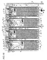
the patient hose 14 is connected to the absorption port of the lying member L1; the discharge port 8 of lying member L1 and the absorption port 7 of the lying member L2, the discharge port 8 of lying member L2 and the absorption port 7 of the lying member L3, and the discharge port 8 of lying member L3 and the absorption port of the lying member L4 are respectively serially connected with the connection pipe 15; the connection pipe 15 connected to the discharge port 8 of the lying member L4 arranged at the terminal row is connected to the closing stopper 16 of the lid 3; and the absorption pressure is applied from the exhaust port 9 of each lying member L. Each lying member L contains the float 5 retaining the solidifying agent 6 and the stop valve 9a serves to cease the absorption pressure from the exhaust port 9 when the float 5 floats inside the liquid waste 21 and reaches the ceiling portion.
Description
- The entire disclosure of Japanese patent application No. 2000-182728 filed on June, 19 2000, including the specification, claims, accompanying drawings and abstract of the disclosure is incorporated herein by reference in its entirety, in order to claim priority right according to 35 U.S.C. §119.
- This invention relates to a liquid waste disposal apparatus serving to absorb, to solidify and to dispose a liquid waste such as unwanted blood, other body fluids, secretion derived from a medical scene or pus or physiological sodium chloride solution used for cleansing affected areas.
- A liquid waste (e.g. unwanted blood, other body fluids, secretion, pus, or physiological sodium chloride solution used for cleansing affected areas) derived from medical scenes, particularly at a scene of surgical operation, is collected into a container or a collecting bag for disposal and incineration by an absorbing apparatus.
- However, since the liquid waste may contain a harmful bacteria or the like, a secondary infection may occur among medical employees, hospital patients and the like, when the container or the collecting bag becomes damaged or when an excessive amount of the liquid waste is absorbed exceeding a capacity of the collecting bag.
- For preventing thus created problem, an apparatus for solidifying a liquid waste with a water-absorptive material arranged inside a collecting bag is provided and methods for arranging the liquid waste solidifying water-absorptive material inside the collecting bag are provided such as: a method of forming a collecting bag with a non-water permeable sheet and a water-absorptive sheet stuck with each other in which the water-absorptive sheet is arranged as an inner surface, a method of dropping a prepared water-absorptive material into a collecting bag after an absorption of liquid waste, or a method of fixing a water-absorptive material at a bottom portion of a collecting bag.
- Furthermore, in means to increase the liquid waste disposing capacity of a liquid waste disposal apparatus, a liquid waste disposal apparatus having 2 continuously arranged collecting bags, or a liquid waste disposal apparatus having 4 or 6 consecutively arranged collecting bags disposed along a same circumference on top of a wheeled base are being proposed, and further, a shutting off valve or the like could be provided at the terminal row of the collecting bags for automatically stopping an absorption of the liquid waste when multiple collecting bags are serially connected to form a straight line.
- Nevertheless, when the multiple collecting bags are connected along a same circumference for increasing the liquid waste disposing capacity, a user of the disposing apparatus could not easily confirm the remaining containment capacity of the disposing apparatus since the collecting bags were unable to be viewed from a single direction.
- Further, when the multiple collecting bags are connected forming a straight line, a special kind of collecting bag differentiated from the rest of the collecting bags is required for a collecting bag arranged at the terminal row since the collecting bag arranged at the terminal row is requires the shutting off valve; accordingly, thus requiring of a different kind of collecting bag raises a problem of increasing production costs and increasing product management costs.
- Further, the disposal apparatus structured with the non-water permeable sheet and the water-absorptive sheet stuck with each other caused an inner portion to be unable to be seen from outside and also caused difficulty of folding and also caused inconvenience during storage and transport owing to a multiple overlapping structure of the disposal apparatus.
- Further, the disposal apparatus using the method of dropping a prepared water-absorptive material into a collecting bag after the absorption of liquid waste is unable to perform further absorption once a solidification process is completed and also a danger remained when toppled during the middle of an operating process since solidification would not proceed until the water-absorptive material is dropped inside the collecting bag.
- A disposal apparatus using the method of fixing a water-absorptive material at a bottom portion of a collecting bag would cause a solidifying speed to decrease in association with the proceeding of the liquid waste absorption process.
- This invention is aimed to solve the foregoing problems, and an object thereof resides in providing a multiply connected type liquid waste disposal apparatus to unify the kind of canister bottles used for multiple connection, to provide plural patient hoses for separate use, to enable easy visual recognition of a containment capacity even if a liquid waste disposing capacity is increased, and to solidify more rapidly an absorbed liquid waste.
- The multiple continuous type liquid waste disposal apparatus regarding this invention comprises: n (n being equal to or more than 3 ) connected canister bottles; the canister bottles having an absorption port and a discharge port; the canister bottles containing a liquid waste absorbed from the absorption port; the canister bottles enabling the contained liquid waste to be seen from outside, wherein: the discharge port of a first canister bottle is connected to the absorption port of a second canister bottle, and the discharge port of the second canister bottle is connected to the absorption port of a third canister bottle, and ··· the discharge port of n - I canister bottle is connected to the absorption port of n canister bottle; and the foregoing canister bottles form a straight line by being serially connected in an order starting from the first canister bottle to the n canister bottle.
- Thus structured, this invention enables all of the canister bottles to be viewed from a single direction by serially connecting the canister bottles in an order starting from the first canister bottle to the n (n being equal to or more than 3 ) canister bottle and forming a straight line; this invention also allows the user of the disposal apparatus to easily confirm the remaining containment capacity of the disposal apparatus since the liquid waste is contained in an order starting from the first canister bottle to the n canister bottle.
- The multiple continuous type liquid waste disposal apparatus regarding this invention is further structured with plural connected canister bottles, each of the canister bottles having an absorption port for absorbing liquid waste, each of the canister bottles having a discharge port for discharging liquid waste, each canister bottle serving to contain the liquid waste absorbed from the absorption port;
wherein, each of the canister bottles has an exhaust port for creating negative pressure inside the canister bottle; the discharge port of one canister bottle is connected to the absorption port of the other canister bottle in a serially connected manner; and the exhaust port of a terminally arranged canister bottle is closed. - Thus structured, this invention enables the liquid waste to be absorbed and contained consecutively into the serially connected multiple canister bottles by connecting the discharge port of one canister bottle to the absorption port of another canister bottle and forming a serial connection while closing the discharge port of the canister bottle arranged at the terminal row to allow exhaustion from the exhaust port of each canister bottle for internally creating negative pressure.
- This invention could also reduce the kind of canister bottle to allow the reduction of production cost and product management cost since the kind of canister bottle used for the canister bottle arranged at the terminal row is unified with that of the other canister bottles.
- This invention also enables all of the canister bottles to be viewed from a single direction by serially connecting the plural canister bottles in order so as to form a straight line; this invention also allows the user of the disposal apparatus to easily confirm the remaining containment capacity of the disposal apparatus since the liquid waste is contained in the order according to the arrangement of the canister bottles.
- The multiple continuous type liquid waste disposal apparatus regarding this invention is further structured with plural connected canister bottles, each of the canister bottles having an absorption port for absorbing liquid waste, each of the canister bottles having a discharge port for discharging liquid waste, each canister bottle serving to contain the liquid waste absorbed from the absorption port; wherein: each of the canister bottles has an exhaust port for creating negative pressure inside the canister bottle; the canister bottles are separated into at least two groups in which the discharge port of one canister bottle is connected to the absorption port of the other canister bottle in a serially connected manner; each of the separated canister bottle groups has a terminal canister bottle with a closed discharge port; and each of the separated canister bottle groups has a primary canister bottle with a patient hose connected to the absorption port.
- Thus structured, this invention allows the plural patient hoses for each of the separated canister bottle groups to be used separately and enables the liquid waste to be absorbed and contained consecutively into the serially connected multiple canister bottles by providing the foregoing constitution wherein: each of the canister bottles has an exhaust port for creating negative pressure inside the canister bottle; the canister bottles are separated into at least two groups in which the discharge port of one canister bottle is connected to the absorption port of the other canister bottle in a serially connected manner; each of the separated canister bottle groups has a terminal canister bottle with a closed discharge port; and each of the separated canister bottle groups has a primary canister bottle with a patient hose connected to the absorption port.
- This invention could also reduce the kind of canister bottle to allow the reduction of production cost and product management cost since the kind of canister bottle used for the canister bottle arranged at the terminal row of the respective separated canister bottle group is unified with that of the other canister bottles.
- This invention also enables all of the canister bottles to be viewed from a single direction by serially connecting the plural canister bottles regarding each group of canister bottles in an orderly manner so as to form a straight line; this invention also allows the user of the disposal apparatus to easily confirm the remaining containment capacity of the disposal apparatus since the liquid waste is contained in the order according to the arrangement of the canister bottles regarding each group of canister bottles.
- By providing the canister bottle comprised of an outer container having inside an internal bag containing a solidifying agent, the liquid waste could be solidified inside the internal bag so that the internal bag could be solely and sanitarily disposed.
- By providing a float inside the internal bag of the canister bottle in which the float retains the solidifying agent and has a specific gravity less than 1, a liquid level could be easily confirmed from outside by checking the position of the float since the float would always remain afloat at a gas-liquid interface, and the user could also easily confirm the used amount as well as the remaining containment capacity.
- In a process where the liquid waste is absorbed, a water-absorptive material could constantly spread among the newly absorbed liquid waste and swiftly and effectively solidify the liquid waste since the float having a specific gravity less than 1 constantly stays afloat at the liquid-gas interface.
- Even when the absorption is started once again after a cease of the absorption process, solidification could be performed swiftly, and the float could serve as a level gauge for indicating the amount of content since the float constantly stays afloat at the liquid-gas interface. The manufacturing cost would be inexpensive owing to a simple structure of the float.
- The above and other objects and features of the invention are apparent to those skilled in the art from the following preferred embodiments thereof when considered in conjunction with the accompanied drawings, in which:
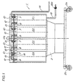
- FIG. 1 is an outer front view showing a structure of a first embodiment of a multiple continuous type liquid waste disposal apparatus regarding this invention;
- FIG.2 is an outer plane view showing a structure of the first embodiment of the multiple continuous type liquid waste disposal apparatus regarding this invention;
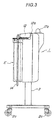
- FIG.3 is an outer side view showing a structure of the multiple continuous type liquid waste disposal apparatus regarding this invention;
- FIG.4 is a side cross-sectional explanatory view for describing an absorption path of the first embodiment of the multiple continuous type liquid waste disposal apparatus regarding this invention;
- FIG.5 is a vertical cross-sectional view for describing an absorption path of the multiple continuous type liquid waste disposal apparatus regarding this invention;
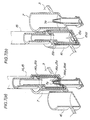
- FIG.6 is a perspective explanatory view showing unified canister bottles in a state where one of the canister bottles could selectively have a closed discharge port when arranged as a terminal canister bottle or could connect to a downstream arranged canister bottle in accordance to circumstance;
- FIG.7 is an explanatory view showing a function of a valve member when a connection tube or a patient hose is connected to a closing stopper and an absorption port arranged at a lid of a ceiling portion of an internal bag;
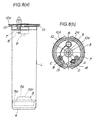
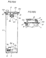
- FIG. 8 (a) is an outer front view showing a structure of an internal bag of a canister bottle and a float contained inside the internal bag and serving to retain a solidifying agent within; FIG. 8 (b) is an outer plane view showing a structure of an internal bag of a canister bottle;
- FIG.9 (a) is a cross-sectional view showing B subtracted by A of FIG.8 (b); FIG.9 (b) is a cross-sectional view showing D subtracted by C of FIG.8 (b);
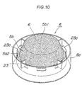
- FIG.10 is a perspective of a structure of a float;
- FIG.11 is an exploded perspective view of a float;
- FIG.12 is a view of a first embodiment of the multiple continuous type liquid waste disposal apparatus regarding this invention showing a state where a liquid waste is absorbed and contained;
- FIG.13 is an outer front view of a second embodiment of the multiple continuous type liquid waste disposal apparatus regarding this invention showing an example where canister bottles are separated into two groups and a patient hose is connected to an absorption port of the respective canister bottle groups;
- FIG. 14 is an outer plane view of a second embodiment of the multiple continuous type liquid waste disposal apparatus regarding this invention showing an example where the canister bottles are separated into two groups and a patient hose is connected to an absorption port of the respective canister bottle groups;
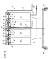
- FIG.15 is front vertical cross-section view of a second embodiment of the multiple continuous type liquid waste disposal apparatus regarding this invention explaining an example of an absorption path wherein the canister bottles are separated into two groups and a patient hose is connected to an absorption port of the respective canister bottle groups; and
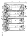
- FIG. 16 is a view of a second embodiment of the multiple continuous type liquid waste disposal apparatus regarding this invention showing a state where a liquid waste is absorbed and contained wherein the canister bottles are separated into two groups and a patient hose is connected to an absorption port of the respective canister bottle groups.
-
- An embodiment of the multiple continuous type liquid waste disposal apparatus regarding this invention will hereinafter be specifically described with reference to the drawings. FIG.1 through FIG.12 are the drawings for explaining a structure of a first embodiment of the multiple continuous type liquid waste disposal apparatus regarding this invention.
- FIG. 1 is an outer front view showing a structure of a first embodiment of a multiple continuous type liquid waste disposal apparatus regarding this invention; FIG.2 is an outer plane view showing a structure of the first embodiment of the multiple continuous type liquid waste disposal apparatus regarding this invention; and FIG.3 is an outer side view showing a structure of the multiple continuous type liquid waste disposal apparatus regarding this invention.
- FIG.4 is a side cross-sectional explanatory view for describing an absorption path of the first embodiment of the multiple continuous type liquid waste disposal apparatus regarding this invention; and FIG.5 is a vertical cross-sectional view for describing an absorption path of the multiple continuous type liquid waste disposal apparatus regarding this invention.
- FIG.6 is a perspective explanatory view showing unified canister bottles in a state where one of the canister bottles could selectively have a closed discharge port when arranged as a terminal canister bottle or could connect to a downstream arranged canister bottle in accordance to circumstance; and FIG.7 is an explanatory view showing a function of a valve member when a connection tube or a patient hose is connected to a closing stopper and an absorption port arranged at a lid of a ceiling portion of an internal bag.
- FIG. 8 (a) is an outer front view showing a structure of an internal bag of a canister bottle and a float contained inside the internal bag and serving to retain a solidifying agent within; FIG.8 (b) is an outer plane view showing a structure of an internal bag of a canister bottle; FIG.9 (a) is a cross-sectional view showing B subtracted by A of FIG.8 (b); FIG.9 (b) is a cross-sectional view showing D subtracted by C of FIG.8 (b); FIG.10 is a perspective of a structure of a float; FIG.11 is an exploded perspective view of a float; and FIG.12 is a view of a first embodiment of the multiple continuous type liquid waste disposal apparatus regarding this invention showing a state where a liquid waste is absorbed and contained.
- The embodiment described hereinafter relates to one example of a medical liquid waste disposal apparatus in which a liquid waste 21 (such as dispensable blood, other body fluids, secretion, pus, or physiological sodium chloride solution used for cleansing affected areas produced during operation and treatment) is absorbed into a lying member L serving as an internal bag for a canister bottle E so that the lying member L could be incinerated inclusive of the absorbed liquid waste.
- As shown in FIG.1 through FIG.5, a multiple continuous type liquid waste disposal apparatus 1 of this embodiment having a canister bottle comprised of a lying member L serving as an internal bag for containing
liquid waste 21 and a bottle M serving as an outer container for containing the lying member L in a detachably attached manner, wherein at least 2 or more canister bottles E are connected in series to form a straight line and are supported by astand 2. - The bottle M shown in FIG.4 and FIG.5 is supported by the
stand 2 in a detachably attached manner, and acaster 2a is attached to a leg portion of thestand 2. Thus structure allows thestand 2 to steadily move the 2 or more plural canister bottles E in a state where the canister bottles E are supported and arranged in a straight line. - The bottle M is a transparent plastic cylindrical container having an engagement portion arranged at a rear side for detachably engaging with the
stand 2 and a graduation formed at a surface for indicating capacity. - The lying member L is a united body having a circular
plastic lid 3 thermally welded to an opening portion of a flexible cylindricaltransparent bag 4 made from a low density polyethylene. Therefore, the canister bottle E comprised of the bottle M containing the lying member L allows the absorbed and containedliquid waste 21 to be easily visually recognized, and the graduation formed at the surface of the bottle M enables the confirmation of the amount of theliquid waste 21 and the remaining containment capacity. - A
floatable float 5 is arranged above abottom portion 4 inside the lying member L in which the float has a specific gravity less than 1 and retains a water-absorptive material 6 such as a water-absorptive polymer serving as a solidifying agent. - An
absorption port 7 and andischarge port 8 arranged at thelid 3 are in liquid-communication to an inside of the lying member L wherein theabsorption port 7 absorbs theliquid waste 21 into the lying member L and thedischarge port 8 discharges theliquid waste 21 to theabsorption port 7 of an adjoining lyingmember 21. - An
exhaust port 9 exhausting air from the lyingmember 21 for creating a negative pressured state is arranged at a central portion of thelid 3 in an air-communication manner to the inside of the lying member L. Further, a ring-shapedholder 10 having acatch 10a is engaged and fixed to a peripheral portion of thelid 3. - The
holder 10 is a united body in which a plastic annular body for engaging and fixing an opening periphery of the bottle M is molded to thecatch 10a. - When inserting the lying member L into the bottle M, as shown in FIG.2, FIG.3 and FIG.5, a
canister head 12 arranged opposite to thestand 2 and pivotally movable around apivotal movement shaft 12a as a center would pivotally move and open so that the lying members L1, L2, L3, L4 could respectively be inserted into the four bottles M1, M2, M3, M4 in which the bottles are fixed to thestand 2 and arranged in a straight line. - As shown in FIG.4 and FIG.5, when the lying member L is inserted into the bottle M, a cylindrical portion of the holder engaged to an outer peripheral portion of the
lid 3 arranged at the ceiling portion of the lying member L is engagedly inserted to the opening portion of the bottle M and thus, a packing 11 arranged at an opening peripheral rim of the bottle M contacts to a collar portion of theholder 10. - When the
canister head 12 is closed by pivotally moving the canister head downward around thepivotal movement shaft 12a as the center, as shown in FIG.5, anabsorption path 13 arranged at thecanister head 12 is connected in air-communication with theexhaust port 9 arranged at thelid 3 of the lying member L, and at the same time, thelid 3 of the lying member L is fixed to the bottle M via theholder 10 creating an air-tight sealed state at the space between the bottle M and the lying member L via the packing 11 where thelid 3 and theholder 10 are unitedly pressed against the bottle M fixed by thestand 2. - A
patient hose 14 is connected to theabsorption port 7 arranged at thelid 3 of a first lying member L1 in a state where a first canister bottle E1, a second canister bottle E2, a third canister bottle E3 and a fourth canister bottle E4 are disposed in a straight line and arranged in an order starting from the first lying member L1 to the second canister bottle E2 to the third canister bottle E3 and to the fourth canister bottle E4; thepatient hose 14 is applied to a portion such as an affected portion of a patient so as to absorb theliquid waste 21 such as dispensable blood, other body fluids, secretion, pus, or physiological sodium chloride solution used for cleansing affected areas produced during operation and treatment. - The
absorption port 7 arranged at thelid 3 of the second lying member L2 is connected to thedischarge port 8 arranged at thelid 3 of the first lying member L1 via aconnection pipe 15, and theabsorption port 7 arranged at thelid 3 of the third lying member L3 is connected to thedischarge port 8 arranged at thelid 3 of the second lying member L2 via theconnection pipe 15, and theabsorption port 7 arranged at thelid 3 of the fourth lying member L4 is connected to thedischarge port 8 arranged at thelid 3 of the third lying member L3 via theconnection pipe 15. - A closing
stopper 16 arranged at thelid 3 of the fourth lying member L4 is connected to thedischarge port 8 arranged at thelid 3 of the lying member L4 of the terminal row, that is, the canister bottle E4 via theconnection pipe 15; accordingly, thedischarge port 8 arranged at thelid 3 of the lying member L4 of the terminal row, that is, the canister bottle E4 becomes closed. - As shown in FIG.6, an end portion of the
connection pipe 15 is connected to thedischarge port 8 arranged at thelid 3 of the respective lying member L in a pivotally movable and airtight manner. The pivotally moving theconnection pipe 15 around thedischarge port 8 as a center allows another end portion of theconnection pipe 15 to selectively connect with either theabsorption port 7 formed at thelid 3 of a lying member L adjoined downstream (left side of FIG.6) or the closingstopper 16 of thuslid 3 - Accordingly, as shown in FIG.6, when a lying member Ln arranged at the terminal row is connected to a downstream arranged lying member L n+l for newly making the lying member L n+l to become the lying member L arranged at the terminal row, the opening rim portion of the
connection pipe 15 illustrated with a full line in FIG.6 and rotatively attached to thedischarge port 8 of thelid 3 of the lying member Ln (shown in FIG.7) is pulled out from the closingstopper 16, and then is inserted and connected to theabsorption port 7 of thelid 3 of the lying member Ln+l illustrated with a broken line in FIG.6, and further, an opening rim portion of theconnection pipe 15 rotatively attached to thedischarge port 8 of thelid 3 of the lying member Ln+l is inserted to a closingstopper 16 of thelid 3 for closure. - A
valve member 15a is arranged at an opening rim portion of theconnection pipe 15 and as shown in FIG.8 (a), when connecting the opening rim portion of theconnection pipe 15 to theabsorption port 7, theconnection pipe 15 is in air-communication with theabsorption port 7 in which a projecting portion 7a arranged at a surrounding of an opening portion of theabsorption port 7 is pushed upward to open a rubber valve 15a1 formed at thevalve member 15a and further, a letter O shaped ring arranged at an outer peripheral portion of thevalve member 15a is pressingly contacting to an inner wall of an opening portion of theabsorption port 7 so as to maintain an airtight state. - As shown in FIG.8 (b), when connecting the opening rim portion of the
connection pipe 15 to the closingstopper 16, theconnection pipe 15 is closed in a state where a letter O shaped ring arranged at an outer peripheral portion of thevalve member 15a is pressingly contacting to an inner wall of an opening portion of the closingstopper 16 so as to maintain an airtight state while the rubber valve 15a1 remains shut. - Likewise, a
valve member 14a is arranged at an end portion connected to thepatient hose 14 on the side of the liquid waste disposal apparatus 1, and in a state where the end portion of thepatient hose 14 is connected to theabsorption port 7, thepatient hose 14 is in air-communication with theabsorption port 7 in which a projecting portion 7a arranged at a surrounding of an opening portion of theabsorption port 7 is pushed upward to open a rubber valve 14a1 formed at thevalve member 14a and further, a letter O shaped ring arranged at an outer peripheral portion of thevalve member 14a is pressingly contacting to an inner wall of an opening portion of theabsorption port 7 so as to maintain an airtight state. - As shown in FIG.2 and FIG.5, a controller 17 having an
adjustment handle 17a for adjusting an absorption pressure (vacuum pressure) is arranged to thestand 2; the controller 17 is connected to aprimary absorption hose 18 connected to a terminal takeout port (outlet valve) or an air pump of an absorption piping of a medical gas piping installation in which an adjusted absorbing pressure of the controller 17 causes an inside of the lying member L to become negative pressure via theabsorption path 13 and anabsorption path 20 of theexhaust port 9. - On the other hand, as shown in FIG.5, the
absorption path 13 is in air-communication with anabsorption path 19 in which theabsorption path 19 is connected to a gap between the bottle M and the lying member L. Since both an absorption pressure inside the lying member L and an absorption pressure of the gap between the bottle M and the lying member L are negatively pressured with an equal absorption pressure, the air pressure inside and outside of the lying member L arranged inside the bottle M becomes equal and thus, a steady absorption could be performed while maintaining a state shown in FIG.5 without causing the lying member L formed with a flexible sheet to expand and contract. - A
stop valve 9a is arranged at theexhaust port 9 and thus at an inner side of an end portion of the lying member L; further, as shown by the canister bottles E2, E3, E4 of FIG.12, a self-weight of thestop valve 9a allows thestop valve 9a to maintain a downward position until thefloat 5 floats to reach the ceiling portion and subsequently, theabsorption path 20 in air-communication with theabsorption path 13 from inside the lying member L could be maintained. - On the other hand, as shown by the canister bottle E1 of FIG.12, when the
liquid waste 21 is absorbed into the lying member L to elevate thefloat 5 until thefloat 5 reaches the ceiling portion of the lying member L, a ceiling edge surface 5b1 of thefloat 5 makes contact to thestop valve 9a and pushes thestop valve 9a upward against the self-weight of thestop valve 9a and causes theabsorption path 20 in air-communication with theabsorption path 13 from inside the lying member L to become closed. - Once the
stop valve 9a is pushed upward to close theabsorption path 20, owing to an absorbing strength of exhaust, thestop valve 9a adheres to acylindrical body 9b arranged above so as to maintain the closed state of theabsorption path 20. - The
float 5 shown in FIG.10 and FIG.11 is placed on the bottom portion 4a of the lying member. Thefloat 5 is structured to have a specific gravity less than 1, and as shown in FIG.12, thefloat 5 always stays afloat at liquid-gas interface of theliquid waste 21 when theliquid waste 21 flows into the lying member L. - The
float 5 is supported by an inner edge portion of theannular member 5a in a manner where a solidifying agent such as a water-absorptive polymer is filled and retained by thecup portion 5b in which thecup portion 5b has a face down shape with a downward opening; and thus, theannular member 5a and thecup portion 5b according to this embodiment are formed with polypropylene having a specific gravity less than 1. - As shown in FIG.4 through FIG.10, an outer diameter of the
annular member 5a of thefloat 5 is formed smaller than an inner diameter of the lying member L, a bottom portion of thecup 5b is opened in a state where thefloat 5 is contained inside the lying member L. - In a filling process of the water-
absorptive material 6 into thecup portion 5b of thefloat 5, as shown in FIG. 11, after the water-absorptive material 6 has been filled into thecup portion 5b where thefloat 5 is in an upside down state, a fixingring 23 is engaged to peripheral portion of thecup portion 5b in a state covered by a waterpermeable sheet 22 e.g. Japanese traditional paper, and further aclaw portion 23a of the fixingring 23 is engaged to step portion 5b2 formed at a peripheral edge portion of thecup portion 5b. - The
liquid waste 21 absorbed into the lying member L from theabsorption port 7 comes around to a bottom portion via a gap between the lying member L and theannular member 5a or a gap between thecup portion 5b and theannular member 5a; then theliquid waste 21 permeates through the waterpermeable sheet 22 spread and stretched at a peripheral rim portion of thecup portion 5b and contacts to the water-absorptive material 6 so that the water-absorptive material 6 would swell to tear the waterpermeable sheet 22 and dissolve into theliquid waste 21 contained inside the lying member L to solidify theliquid waste 21 into a gel. - Hereinafter an operating procedure and an operation of the liquid waste disposal apparatus 1 will be specifically described. The lying member L is preserved and transported in a state where the
holder 10 remains attached by a method such as sealing the lying member L with a vinyl-wrapping container. In thus situation, thecatch 10a arranged at theholder 10 could be laid down to both sides of thelid 3, and the lying member L could be preserved and transported in a relatively compact manner since the lying member L itself is flexible. - At a time for operation, the lying member L is prepared in correspondence with the number of the bottle M arranged in a straight line at the
stand 2, and then, theadjustment handle 17a is turned in a counter clockwise direction shown in FIG.2 so as to turn the controller 17 off, and then anadapter 18a of theprimary absorption hose 18 is connected to a terminal takeout port or an air pump of a medical gas piping installation (not shown). - Next, the
canister bottle 12 of thestand 2 is opened to insert the lying member L into all of the bottles M, and then, theconnection pipe 15 rotatively attached to thedischarge port 8 formed at thelid 3 of the ceiling portion of the respective lying members L is inserted and connected to theabsorption port 7 formed at thelid 3 of the ceiling portion of the lying member L adjoined to the left side in FIG.4. - The end portion on the side of the
valve member 14a of thepatient hose 14 is inserted and connected to theabsorption port 7 formed at thelid 3 of the ceiling portion of the lying member L1 of the first canister bottle E1 and further, in means for closure, the closingstopper 16 formed at thelid 3 of the lying member L4 is connected to theconnection pipe 15 in which theconnection pipe 15 is connected to thedischarge port 8 formed at thelid 3 of the lying member L4 of the fourth canister bottle E4 serving as the terminal canister bottle. - Next, the
canister head 12 is closed and locked to thestand 2. Before the beginning of absorption, thefloat 5 is arranged at thebottom portion 4 of the lying member L as shown in FIG.4 owing to the weight of thefloat 5 itself. - Then, the
adjustment handle 17a of the controller 17 is turned clockwise as shown in FIG.2 so as to turn the controller 17 for adjusting to a prescribed absorption pressure. In thus case, the negative pressure of theprimary absorption hose 18 causes the inside of the lying member L to become negative pressure via theabsorption path 13 formed at the respective canister heads 12 and theabsorption path 20 of theexhaust port 9 formed at thelid 3 of the ceiling portion of the respective lying members L; further, the gaps between the respective bottles M and the respective lying members L are also caused to become negative pressure via theabsorption path 19 in air-communication with the gaps between the respective bottles M and the respective lying members L. - In this process, the presence of absorption pressure inside the lying member L is to be confirmed by closing a tip of the
patient hose 14 and whether or not the lying member L inflates along the bottle M is also to be confirmed. - When an absorption of the
liquid waste 21 is started after a tip of thepatient hose 14 is applied to such as an affected area of the patient, as shown in FIG.12, theliquid waste 21 from thepatient hose 14 is guided into the lying member L via theabsorption port 7 formed at thelid 3 of the lying member L1 of the first canister bottle E1. - The
liquid waste 21 absorbed into the lying member L1 reaches below thefloat 5 via the gap between the lying member L1 and theannular member 5a of thefloat 5 or via the gap between thecup portion 5b and theannular member 5a of thefloat 5. - Since the
float 5 has a specific gravity less than 1thefloat 5, the float maintains a position at the level of theliquid waste 21 and stays afloat at liquid-gas interface; thus, theliquid waste 21 permeates through the waterpermeable sheet 22 spread and stretched at a bottom surface of a peripheral rim portion of thecup portion 5b of thefloat 5 and contacts to the water-absorptive material 6 so that the water-absorptive material 6 would swell to tear the waterpermeable sheet 22 and spread among theliquid waste 21 and solidify theliquid waste 21 into a gel. - Even after the progress of the absorption of the
liquid waste 21, the water-absorptive material 6 could effectively spread among theliquid waste 21 absorbed afterwards and solidify thusliquid waste 21 into a gel since thefloat 5 constantly stays afloat at the liquid-gas interface. - Further, since the
float 5 constantly stays afloat at the liquid-gas interface, the amount of the absorbedliquid waste 21 could easily be visually recognized so that thefloat 5 could function as a level gauge as well. Therefore, it is suitable for such as theannular member 5a or thecup portion 5b of thefloat 5 to be formed with a material having a color distinguishable with the color of theliquid waste 21 or a distinguishing color such as a florescent color. - As shown in FIG.12, as the absorption process of the
liquid waste 21 progresses, thefloat 5 elevates to the ceiling portion of the lying member L and then, the ceiling edge surface 5b1 serving as the upward-pushing portion of thecup portion 5b of thefloat 5 pushes thestop valve 9a upward against the weight of thestop valve 9a so that theabsorption path 20 becomes closed and the absorption pressure from theexhaust port 9 would cease, as a manner as first canister bottle E1 of FIG.12. - With the cease of the absorption pressure inside the lying member L1, an absorption pressure of the L2 adjoined at the left side of the lying member L1 in FIG.12 affects the inside of the lying member L1 via the
absorption path 13 of thestand 2, theabsorption path 20 of theexhaust port 9 of the lying member L2, theabsorption port 7 of the lying member L2, theconnection pipe 15, thedischarge port 8 of the lying member L1; the not-yet gelledliquid waste 21 absorbed above thefloat 5 inside the lying member L1 is absorbed into the lying member L2 via thedischarge port 8 of the lying member L1, theconnection pipe 15 and the absorption port of the lying member L2. - In the same manner as the foregoing lying member L1, the
float 5 elevates and stays afloat at the level of theliquid waste 21 in correspondence with the rise in the level of theliquid waste 21 contained inside the lying member L2, and when thefloat 5 reaches the ceiling portion of the lying member L2, the ceiling edge surface 5b1 of thefloat 5 pushes thestop valve 9a upward to close theabsorption path 20 and cease the absorption pressure of the lying member L2. - Likewise, an absorption pressure of the lying member L3 adjoined to the lying member L2 absorbs the absorbed
liquid waste 21 contained above thefloat 5 of the lying member L2 into the lying member L3 via thedischarge port 8 of the lying member L2, theconnection pipe 15 and the absorption port of the lying member L3. - In the same manner as the foregoing lying members L1, L2, the
float 5 elevates and stays afloat at the level of theliquid waste 21 in correspondence with the rise in the level of theliquid waste 21 contained inside the lying member L3, and when thefloat 5 reaches the ceiling portion of the lying member L2, the ceiling edge surface 5b1 of thefloat 5 pushes thestop valve 9a upward to close theabsorption path 20 and cease the absorption pressure of the lying member L3. - Likewise, an absorption pressure of the lying member L4 adjoined to the lying member L3 absorbs the absorbed
liquid waste 21 contained above thefloat 5 of the lying member L3 into the lying member L4 via thedischarge port 8 of the lying member L3, theconnection pipe 15 and the absorption port of the lying member L4. - In the same manner as the foregoing lying members L1, L2, L3, the
float 5 elevates and stays afloat at the level of theliquid waste 21 in correspondence with the rise in the level of theliquid waste 21 contained inside the lying member L4, and when thefloat 5 reaches the ceiling portion of the lying member L4, the ceiling edge surface 5b1 of thefloat 5 pushes thestop valve 9a upward to close theabsorption path 20 and cease the absorption pressure of the lying member L4. - Therefore, since each
float 5 upwardly pushes and activates thestop valve 9a, the absorption of theliquid waste 21 is automatically ceased before all of the lying members L become full withliquid waste 21; accordingly, the air-pump or the like would not malfunction due to an excessive absorption into the respective lying members L. - After the use of the liquid waste disposal apparatus, the lying member L is taken out from the bottle M by opening the
canister head 12 of thestand 2, and then, an end portion of theconnection pipe 15 is inserted and connected to theabsorption port 7 arranged at thelid 3 wherein another end-portion of the connection pipe is rotatively connected to thedischarge port 8 of thelid 3 of the respective lying members L, and then, as shown in FIG.5, FIG.6, FIG.8 (b) and FIG.9 (a), acap 24 prearranged to thelid 3 covers theexhaust port 9 arranged at thelid 3 of the respective lying members L for hermetically sealing the lying members L, and subsequently, pulling out the lying member L with thecatch 10a of theholder 10 enables easy detachment from the bottle M so that the lying member L could solely be disposed by incineration and the like. - Further, the lying member could be solely stood upright owing to a function of the
bottom portion 4 of the lying member L in a state where theliquid waste 21 inside the lying member L is gelled by the water-absorptive material 6. - The
liquid waste 21 remaining inside theconnection pipe 15 or thepatient hose 14 would not drip down during a detachment of thepatient hose 14 or theconnection pipe 15 from theabsorption port 7 owing to a function of the rubber valves 14a1, 15a1 of thevalve members connection pipe 15 or thepatient hose 14. - Although this embodiment is described showing 4 canister bottles E1, E2, E3, and E4 arranged in a straight line in which the
discharge port 8 of thelid 3 of each lying member L is connected to theabsorption port 7 of thelid 3 of each adjoining lying member L, this invention could be structured having n canister bottles (n being equal to or more than 2) arranged in a straight line in which thedischarge port 8 of thelid 3 of the first lying member L1 of the first canister bottle E1 is connected to theabsorption port 7 of thelid 3 of the second lying member L2 of the second canister bottle E2, and thedischarge port 8 of thelid 3 of the second lying member L2 of the second canister bottle E2 is connected to theabsorption port 7 of thelid 3 of the third lying member L3 of the third canister bottle E3, and ··· thedischarge port 8 of thelid 3 of the n - l lying member of n - l canister bottle is connected to theabsorption port 7 of thelid 3 of the n lying member Ln of the n canister bottle En. - Thus structured, the
liquid waste 21 could be absorbed and contained consecutively into the lying member L of the serially connected multiple canister bottles E by connecting thedischarge port 8 of thelid 3 of the lying member L of one canister bottle E to theabsorption port 7 of thelid 3 of the lying member L of another canister bottle E via theconnection pipe 15 and forming a serial connection while closing thedischarge port 8 of the canister bottle E4 arranged at the terminal row to allow exhaustion from theexhaust port 9 of each canister bottle E for internally creating negative pressure. - The kind of canister bottle could be reduced to allow the reduction of production cost and product management cost since the kind of lying member L of canister bottle E used for the lying member L4 of canister bottle E4 arranged at the terminal row is unified with that of the other lying members L1, L2, L3 of canister bottles E1, E2, E3.
- All of the canister bottles E could be viewed from a single direction by serially connecting the canister bottles E in an order starting from the first canister bottle E1 to the n (n being equal to or more than 3) canister bottle En and forming a straight line; the user of the disposal apparatus 1 could easily confirm the remaining containment capacity of the disposal apparatus 1 since the
liquid waste 21 is contained in an order starting from the first canister bottle E1 to the n canister bottle En. - By providing the canister bottle E comprised of the bottle M serving as the outer container having inside the lying member L serving as the internal bag containing the
water absorptive material 6 serving as the solidifying agent, theliquid waste 21 could be solidified inside the lying member L so that the lying member L could be solely and sanitarily disposed. - By providing the
float 5 inside the lying member L of the canister bottle E in which thefloat 5 retains the water-absorptive material 6 serving as the solidifying agent and has a specific gravity less than 1, the liquid level of theliquid waste 21 could be easily confirmed from outside by checking the position of thefloat 5 since thefloat 5 would always remain afloat at a gas-liquid interface, and the user could also confirm with certainty the used amount of the canister bottle E as well as the remaining containment capacity. - Next, referring to Figs. 13 to FIG.16, a structure of the multiple continuous type liquid waste disposal apparatus regarding the second embodiment will hereinafter be explained. It should be noted that constitutions similar to those explained in the first embodiment will be assigned with the same reference numerals, while omitting the explanations thereof.
- FIG.13 is an outer front view of the second embodiment of the multiple continuous type liquid waste disposal apparatus regarding this invention showing an example where canister bottles are separated into two groups and a patient hose is connected to an absorption port of the respective canister bottle groups; and FIG.14 is an outer plane view of the second embodiment of the multiple continuous type liquid waste disposal apparatus regarding this invention showing an example where the canister bottles are separated into two groups and a patient hose is connected to an absorption port of the respective canister bottle groups.
- FIG.15 is front vertical cross-section view of the second embodiment of the multiple continuous type liquid waste disposal apparatus regarding this invention explaining an example of an absorption path wherein the canister bottles are separated into two groups and a patient hose is connected to an absorption port of the respective canister bottle groups; and FIG.16 is a view of the second embodiment of the multiple continuous type liquid waste disposal apparatus regarding this invention showing a state where a liquid waste is absorbed and contained wherein the canister bottles are separated into two groups and a patient hose is connected to an absorption port of the respective canister bottle groups.
- As shown in FIG. 13 through FIG. 16, in respect of this embodiment, the first canister bottle E1, the second canister bottle E2, the third canister bottle E3 and the fourth canister bottle E4 are arranged to form a straight line in an order starting from the first canister bottle E1, the second canister bottle E2, the third canister bottle E3 and to the fourth canister bottle E4; a group of canister bottles E comprised of the first canister bottle E1, the second canister bottle E2, the third canister bottle E3 and the fourth canister bottle E4 are separated into two groups which are a group comprising the first canister bottle E1 and the second canister bottle E2, and a group comprising the third canister bottle E3 and the fourth canister bottle E4.
- Separate
patient hoses 14 are respectively connected to theabsorption port 7 arranged at thelid 3 of the first and third lying member L1, L3 of the first and third canister bottle E1, E3 in which both canister bottles serve as the primary canister bottle for each of the separated canister bottle group E; a tip of eachpatient hose 14 is applied upon a portion such as an affected portion of a patient so as to absorb theliquid waste 21 such as dispensable blood, other body fluids, secretion, pus, or physiological sodium chloride solution used for cleansing affected areas produced during operation and treatment. - The
discharge port 8 arranged at thelid 3 of the first lying member L1 is connected to theabsorption port 7 arranged at thelid 3 of the second lying member L2 via theconnection pipe 15, and thedischarge port 8 arranged at thelid 3 of the third lying member L2 is connected to theabsorption port 7 arranged at thelid 3 of the fourth lying member L4 via theconnection pipe 15; each group of the plural canister bottles E are serially connected in order to form a straight line. - Via the
connection pipe 15, each closingstopper 16 arranged at thelid 3 of the second and fourth lying member L2, L4 is respectively connected to thedischarge port 8 arranged at thelid 3 of the lying members L2, L4 of the canister bottles E2, E4 in which both canister bottles serve as the terminal canister bottle for each of the separated canister bottle groups; accordingly, eachdischarge port 8 arranged at thelid 3 of the lying members L2, L4 of the canister bottles E2, E4 serving as the terminal canister bottle for each of the separated canister bottle groups becomes closed. - Consequently, in correspondence with the number of
patient hoses 14 required for use and the absorption amount ofliquid waste 21 absorbed from each patient hose, a desired number of canister bottles E could be serially connected with use of theconnection pipe 15, and the group of canister bottles E could be separated in correspondence with the number ofpatient hoses 14 required for use. - In means to alter the number of separated canister bottles, the opening rim portion of the
connection pipe 15 rotatively attached to the discharge port of thelid 3 of the terminal lying member L of a newly separated canister bottle group is pulled out from theabsorption port 7 of an upstream adjoined lying member L, and then is inserted to the closingstopper 16 of thelid 3 of the terminal lying member L for closure, and further, apatient hose 14 is inserted and connected to theabsorption port 7 of thelid 3 of the primary lying member L of the newly separated canister bottle group. - Likewise, a
valve member 14a is arranged at an end portion connected to thepatient hose 14 on the side of theabsorption port 7, and in a state where the end portion of thepatient hose 14 is connected to theabsorption port 7, thepatient hose 14 is in air-communication with theabsorption port 7 in which a projecting portion 7a arranged at a surrounding of an opening portion of theabsorption port 7 is pushed upward to open a rubber valve 14a1 formed at thevalve member 14a and further, a letter O shaped ring arranged at an outer peripheral portion of thevalve member 14a is pressingly contacting to an inner wall of an opening portion of theabsorption port 7 so as to maintain an airtight state. - A
stop valve 9a is arranged at theexhaust port 9 and thus at an inner side of an end portion of the lying member L; further, as shown by the canister bottles E2, E4 of FIG. 16, a self-weight of thestop valve 9a allows thestop valve 9a to maintain a downward position until thefloat 5 floats to reach the ceiling portion and subsequently, theabsorption path 20 in air-communication with theabsorption path 13 from inside the lying member L could be maintained. - On the other hand, as shown by the canister bottles E1, E3 of FIG.16, when the
liquid waste 21 is absorbed into the lying member L to elevate thefloat 5 until thefloat 5 reaches the ceiling portion of the lying member L, a ceiling edge surface 5b1 of thefloat 5 makes contact to thestop valve 9a and pushes thestop valve 9a upward against the self-weight of thestop valve 9a and causes theabsorption path 20 in air-communication with theabsorption path 13 from inside the lying member L to become closed. - In the same manner as the first embodiment, the
canister bottle 12 of thestand 2 is opened to insert the lying member L into all of the bottles M, and then, in the number according to necessity, theconnection pipe 15 rotatively attached to thedischarge port 8 formed at thelid 3 of the ceiling portion of the respective lying members L is inserted and connected to theabsorption port 7 formed at thelid 3 of the ceiling portion of the lying member L adjoined to the left side in FIG.15. - This embodiment shows an example where the
connection pipe 15 rotatively attached to thedischarge port 8 formed at thelid 3 of the first lying member L1 is inserted and connected to theabsorption port 7 formed at thelid 3 of the second lying member L2, and theconnection pipe 15 rotatively attached to thedischarge port 8 formed at thelid 3 of the third lying member L3 is inserted and connected to theabsorption port 7 formed at thelid 3 of the fourth lying member L4. - An end arranged at the side of the
valve 14a of eachpatient hose 14 is inserted and connected to eachabsorption port 7 formed at thelid 3 arranged at the ceiling edge portion of the lying members L1, L3 of the first and third canister bottles E1, E3 serving as the primary canister bottle for each of the separated canister bottle groups. - Each closing
stopper 16 formed at thelid 3 of the lying members L2, L4 is closed by connecting to eachconnection pipe 15 connected to thedischarge port 8 formed at thelid 3 arranged at the ceiling edge of the lying members L2, L4 of the second and fourth canister bottles E2, E4 serving as the terminal canister bottle for each of the separated canister bottle groups. - In this process, the presence of absorption pressure inside the lying member L is to be confirmed by closing a tip of each
patient hose 14 and whether or not the lying member L inflates along the bottle M is also to be confirmed. - As shown in FIG. 16, after a tip of each
patient hose 14 is applied to an affected area or the like of a same patient or a different patient, and after the absorption of theliquid waste 21 is started, theliquid waste 21 from eachpatient hose 14 is guided into the lying members L1, L3 via theabsorption port 7 formed at thelid 3 of the lying members L1, L3 of the first and third canister bottles E1, E3. - The
liquid waste 21 absorbed into the lying member L1, L3 reaches below thefloat 5 via the gap between the lying members L1, L3 and the respectiveannular member 5a of thefloat 5 or via the gap between thecup portion 5b and theannular member 5a of thefloat 5. - Since each
float 5 has a specific gravity less than 1thefloat 5, the float maintains a position at the level of theliquid waste 21 and stays afloat at liquid-gas interface; thus, theliquid waste 21 permeates through the waterpermeable sheet 22 spread and stretched at a bottom surface of a peripheral rim portion of thecup portion 5b of thefloat 5 and contacts to the water-absorptive material 6 so that the water-absorptive material 6 would swell to tear the waterpermeable sheet 22 and spread among theliquid waste 21 and solidify theliquid waste 21 into a gel. - As shown in FIG.16, as the absorption process of the
liquid waste 21 progresses, eachfloat 5 elevates to the ceiling portion of the lying member L and then, the ceiling edge surface 5b1 of thecup portion 5b of thefloat 5 pushes thestop valve 9a upward against the weight of thestop valve 9a so that theabsorption path 20 becomes closed, and as shown in a manner as the first and third canister bottle E1, E3 in FIG.16, the absorption pressure from theexhaust port 9 ceases. - With the cease of the absorption pressure inside the respective lying members L1, L3, an absorption pressure of each lying member L2, L4 adjoined at the left side of the respective lying members L1, L3 in FIG. 16 affects the inside of the lying members L1, L3 via the
absorption path 13 of thestand 2, theabsorption path 20 of theexhaust port 9 of the lying members L2, L4, theabsorption port 7 of the lying members L2, L4, theconnection pipe 15 and thedischarge port 8 of the lying members L1, L3; the not-yet gelledliquid waste 21 absorbed above thefloat 5 inside the lying member L1, L3 is respectively absorbed into the lying members L2, L4 via thedischarge port 8 of the lying member L1,L3, theconnection pipe 15 and the absorption port of the lying member L2, L4. - In the same manner as the foregoing lying members L1, L3, the
float 5 elevates and stays afloat at the level of theliquid waste 21 in correspondence with the rise in the level of theliquid waste 21 contained inside the lying member L2, L4 and when eachfloat 5 reaches the ceiling portion of the lying member L2, L4, the ceiling edge surface 5b1 of thefloat 5 pushes thestop valve 9a upward to close theabsorption path 20 and cease the absorption pressure of the respective lying members L2, L4. - Although this embodiment is described showing a group of 4 canister bottles E1, E2, E3, E4 arranged in a straight line and separated into two groups (one group comprising the first and second canister bottle E1, E2, and the other group comprising the third and fourth canister bottle E3, E4), the group of plural canister bottles E could also be separated into other number of groups of plural canister bottles having a suitable amount of canister bottles arranged in a straight line.
- Further, the
patient hose 14 connected to the canister bottle E could be of a singular patient hose. - Thus structured, the
plural patient hoses 14 for each of the separated canister bottle groups E to be used separately and enables theliquid waste 21 to be absorbed and contained consecutively into the serially connected multiple canister bottles E by providing the structure wherein: each of the canister bottles E has anexhaust port 9 for internally creating negative pressure; the canister bottles E are separated into at least two groups in which thedischarge port 8 of one canister bottle E is connected to theabsorption port 7 of the other canister bottle E in a serially connected manner; each of the separated canister bottle groups has a terminal canister bottle E with aclosed discharge port 8; and each of the separated canister bottle groups has a primary canister bottle E with apatient hose 14 connected to theabsorption port 7. - The kind of canister bottle could be reduced to allow the reduction of production cost and product management cost since the kind of canister bottle E used for the canister bottle E arranged at the terminal row of the respective separated canister bottle group is unified with that of the other canister bottles E.
- Further, all of the canister bottles E could be viewed from a single direction by serially connecting the plural canister bottles E regarding each group of canister bottles in an orderly manner so as to form a straight line; this invention also allows the user of the disposal apparatus to easily confirm the remaining containment capacity of the disposal apparatus since the
liquid waste 21 is contained in the order according to the arrangement of the canister bottles E regarding each group of canister bottles. Although theannular member 5a, thecup portion 5b and the fixingring 23 of this embodiment is formed from a polypropylene material having a specific gravity less than 1, as long as the specific gravity of thefloat 5 is less than 1, the material of thus portions is not to be limited to polypropylene. - Although the shape of the
float 5 formed as a cup in a face down manner, the shape of thefloat 5 of this invention is not to be limited and any shape is acceptable as long as the bottom portion of thefloat 5 is opened (e.g. a cylinder or a polygon having a same top surface as the ceiling-edge surface or a shape having a ring-like float at a center with an arm for retaining the water-absorptive material 6). The inner portion of thecup portion 5b serving as a retaining container for retaining the water-absorptive material 6 is desired to have a ventilation hole, a slit or the like for preventing an accumulation of air. - As examples regarding the retaining means for retaining the water-
absorptive material 6 inside thecup portion 5b, the water permeable sheet 22 (e.g. traditional Japanese paper) are given above, however, other means for retaining the water-absorptive material 6 could be used such as a means by solidifying the water-absorptive material 6 with a water-dissolvable filling material, a means by retaining with a water-decomposable non-fabric paper or a non-fabric cloth. - Although the foregoing embodiments are examples describing a
float 5 contained inside the flexible lying member L, the float could be contained inside a container without a flexible structure. - The foregoing description of a preferred embodiment of the invention has been presented for purposes of illustration and description, and is not intended to be exhaustive or to limit the invention to the precise form disclosed. The description was selected to best explain the principles of the invention and their practical application to enable others skilled in the art to best utilize the invention in various embodiments and various modifications as are suited to the particular use contemplated. It is intended that the scope of the invention not be limited by the specification, but be defined by the claims set forth below.
Claims (7)
- A multiple continuous type liquid waste disposal apparatus comprising:
plural connected canister bottles, each of the canister bottles having an absorption port for absorbing liquid waste, each of the canister bottles having a discharge port for discharging liquid waste, each canister bottle serving to contain the liquid waste absorbed from the absorption port;
wherein:each of the canister bottles has an exhaust port for creating negative pressure inside the canister bottle;the discharge port of one canister bottle is connected to the absorption port of the other canister bottle in a serially connected manner; andthe exhaust port of the canister bottle arranged at a terminal row is closed. - The multiple continuous type liquid waste disposal apparatus according to claim 1, wherein the plural canister bottles form a straight line by being serially connected in order.
- A multiple continuous type liquid waste disposal apparatus comprising:
n (n being same as or more than 3 ) connected canister bottles, the canister bottles having an absorption port and a discharge port, the canister bottles containing a liquid waste absorbed from the absorption port; the canister bottles allowing the contained liquid waste to be seen from outside,
wherein:the discharge port of a first canister bottle and the absorption port of a second canister bottle are connected, and the discharge port of the second canister bottle and the absorption port of a third canister bottle are connected, and ··· the discharge port of n - l canister bottle and the absorption port of n canister bottle are connected; andthe canister bottles form a straight line by being serially connected in an order starting from the first canister bottle to the n canister bottle. - A multiple continuous type liquid waste disposal apparatus comprising:
plural connected canister bottles, each of the canister bottles having an absorption port for absorbing liquid waste, each of the canister bottles having a discharge port for discharging liquid waste, each canister bottle serving to contain the liquid waste absorbed from the absorption port;
wherein:each of the canister bottles has an exhaust port for creating negative pressure inside the canister bottle;the canister bottles are separated into at least two groups in which the discharge port of one canister bottle is connected to the absorption port of the other canister bottle in a serially connected manner;each of the separated canister bottle groups has a terminal canister bottle with a closed discharge port; and each of the separated canister bottle groups has a primary canister bottle with a patient hose connected to the absorption port. - The multiple continuous type liquid waste disposal apparatus according to claim 4, wherein each group of the separated plural canister bottles are serially connected in order to form a straight line.
- The multiple continuous type liquid waste disposal apparatus according to any one of the claims 1 through 5, wherein the canister bottle comprises an outer container and an internal bag contained inside the outer container with a solidifying agent contained inside of the internal bag.
- The multiple continuous type liquid waste disposal apparatus according to claim 6, wherein the internal bag of the canister bottle contains a float retaining the solidifying agent and having a specific gravity less than 1.
Applications Claiming Priority (2)
| Application Number | Priority Date | Filing Date | Title |
|---|---|---|---|
| JP2000182728 | 2000-06-19 | ||
| JP2000182728A JP4627353B2 (en) | 2000-06-19 | 2000-06-19 | Multiple liquid waste treatment equipment |
Publications (3)
| Publication Number | Publication Date |
|---|---|
| EP1166805A2 true EP1166805A2 (en) | 2002-01-02 |
| EP1166805A3 EP1166805A3 (en) | 2002-08-21 |
| EP1166805B1 EP1166805B1 (en) | 2008-12-17 |
Family
ID=18683434
Family Applications (1)
| Application Number | Title | Priority Date | Filing Date |
|---|---|---|---|
| EP20010114580 Expired - Lifetime EP1166805B1 (en) | 2000-06-19 | 2001-06-18 | Multiple drainage apparatus |
Country Status (4)
| Country | Link |
|---|---|
| US (1) | US6808515B2 (en) |
| EP (1) | EP1166805B1 (en) |
| JP (1) | JP4627353B2 (en) |
| DE (1) | DE60136996D1 (en) |
Cited By (12)
| Publication number | Priority date | Publication date | Assignee | Title |
|---|---|---|---|---|
| EP2388025A1 (en) * | 2005-12-14 | 2011-11-23 | Stryker Corporation | Removable inlet manifold for a medical/surgical waste collection system, the manifold including a drip stop, the drip stop serving as both a drip stop and a seal |
| CH703478A1 (en) * | 2010-07-30 | 2012-01-31 | Medela Holding Ag | Absaugpumpensystem. |
| WO2012052519A3 (en) * | 2010-10-20 | 2012-10-18 | Birgit Riesinger | Collection device for use in a drainage device |
| US8740866B2 (en) | 2005-12-14 | 2014-06-03 | Stryker Corporation | Medical/surgical waste collection and disposal system including a rover and a docker, the docker having features facilitating the alignment of the docker with the rover |
| CN108030965A (en) * | 2018-02-01 | 2018-05-15 | 苏州市金盛塑胶有限公司 | A kind of sputum aspirator and its production technology |
| CN108671278A (en) * | 2018-05-30 | 2018-10-19 | 孟召阳 | A kind of medical liquid collector |
| CN109331233A (en) * | 2018-09-04 | 2019-02-15 | 西安交通大学医学院第附属医院 | A kind of brain tumor surgery effusion drainage device |
| US10471188B1 (en) | 2019-04-12 | 2019-11-12 | Stryker Corporation | Manifold for filtering medical waste being drawn under vacuum into a medical waste collection system |
| USD919799S1 (en) | 2019-11-11 | 2021-05-18 | Stryker Corporation | Manifold housing for a medical waste collection device |
| US11318242B2 (en) | 2019-04-12 | 2022-05-03 | Stryker Corporation | Manifold for a medical waste collection system |
| USD956967S1 (en) | 2019-11-11 | 2022-07-05 | Stryker Corporation | Manifold housing for a medical waste collection device |
| USD996640S1 (en) | 2019-11-11 | 2023-08-22 | Stryker Corporation | Specimen collection tray |
Families Citing this family (26)
| Publication number | Priority date | Publication date | Assignee | Title |
|---|---|---|---|---|
| JP4532638B2 (en) * | 2000-01-13 | 2010-08-25 | 株式会社群馬コイケ | Float for liquid waste treatment equipment |
| US6893425B2 (en) * | 2002-03-04 | 2005-05-17 | Dornoch Medical Systems, Inc. | High volume liquid waste collection and disposal system |
| US7351234B2 (en) * | 2003-10-14 | 2008-04-01 | Finger Richard B | Urine collection and disposal system |
| CA2872297C (en) | 2006-09-28 | 2016-10-11 | Smith & Nephew, Inc. | Portable wound therapy system |
| US8500706B2 (en) * | 2007-03-23 | 2013-08-06 | Allegiance Corporation | Fluid collection and disposal system having interchangeable collection and other features and methods relating thereto |
| GB0712763D0 (en) | 2007-07-02 | 2007-08-08 | Smith & Nephew | Apparatus |
| US8414519B2 (en) | 2008-05-21 | 2013-04-09 | Covidien Lp | Wound therapy system with portable container apparatus |
| US10912869B2 (en) | 2008-05-21 | 2021-02-09 | Smith & Nephew, Inc. | Wound therapy system with related methods therefor |
| US8177763B2 (en) | 2008-09-05 | 2012-05-15 | Tyco Healthcare Group Lp | Canister membrane for wound therapy system |
| US8827983B2 (en) | 2008-08-21 | 2014-09-09 | Smith & Nephew, Inc. | Sensor with electrical contact protection for use in fluid collection canister and negative pressure wound therapy systems including same |
| EP2441409A1 (en) | 2010-10-12 | 2012-04-18 | Smith&Nephew, Inc. | Medical device |
| US20120193487A1 (en) * | 2011-01-27 | 2012-08-02 | Tsao Yu-Yao | Adjustable vacuum suction bottle support rack |
| CN110141689A (en) | 2013-03-14 | 2019-08-20 | 史密夫和内修有限公司 | System and method for application decompression treatment |
| US9737649B2 (en) | 2013-03-14 | 2017-08-22 | Smith & Nephew, Inc. | Systems and methods for applying reduced pressure therapy |
| RU2016108629A (en) | 2013-08-13 | 2017-09-19 | Смит Энд Нефью, Инк. | SYSTEMS AND METHODS FOR USING LOW PRESSURE THERAPY |
| FI125150B (en) * | 2013-10-16 | 2015-06-15 | Serres Oy | Emptying device, configuration and method for emptying the suction bag |
| EP3174569B1 (en) | 2014-07-31 | 2020-01-15 | Smith & Nephew, Inc | Systems and methods for applying reduced pressure therapy |
| EP3204062B1 (en) | 2014-10-07 | 2021-01-20 | Haemonetics Corporation | System and method for washing shed blood |
| ES2570078B1 (en) * | 2014-11-13 | 2017-02-22 | David CABALLERO CABELLUD | Device for the elimination of chemical substances |
| CA2972701A1 (en) | 2014-12-30 | 2016-07-07 | Smith & Nephew, Inc. | Systems and methods for applying reduced pressure therapy |
| US9855517B2 (en) | 2015-04-24 | 2018-01-02 | Sst Systems, Inc. | Waste liquid solidification system and method |
| US11357906B2 (en) | 2016-02-12 | 2022-06-14 | Smith & Nephew, Inc. | Systems and methods for detecting operational conditions of reduced pressure therapy |
| US10814047B2 (en) * | 2016-04-25 | 2020-10-27 | Allegiance Corporation | Fluid collection systems and methods of use |
| CA3032435A1 (en) | 2016-08-29 | 2018-03-08 | Allegiance Corporation | Port connector for medical waste fluid receptacles and methods of use |
| CN109999240A (en) * | 2019-05-14 | 2019-07-12 | 史灵芝 | A kind of electric suction apparatus |
| JP7269851B2 (en) * | 2019-09-20 | 2023-05-09 | 大研医器株式会社 | Waste liquid storage container, waste liquid reservoir provided with the same, and waste liquid suction system |
Citations (8)
| Publication number | Priority date | Publication date | Assignee | Title |
|---|---|---|---|---|
| US3938540A (en) * | 1971-10-07 | 1976-02-17 | Medical Development Corporation | Vacuum-operated fluid bottle for tandem systems |
| US4388922A (en) * | 1981-07-29 | 1983-06-21 | Becton, Dickinson And Company | Suction canister system for serial collection of fluids |
| EP0394687A2 (en) * | 1989-03-30 | 1990-10-31 | Abbott Laboratories | Suction drainage infection control system |
| JPH0956810A (en) * | 1995-08-28 | 1997-03-04 | Koike Medical:Kk | Treating device of liquid waste |
| WO1998055164A1 (en) * | 1997-06-03 | 1998-12-10 | Femrx, Inc. | Method and apparatus for collecting surgical fluids |
| US6056731A (en) * | 1997-06-03 | 2000-05-02 | B. Braun Melsungen Ag | Suction device for body fluids |
| JP2001190609A (en) * | 2000-01-13 | 2001-07-17 | Gunma Koike:Kk | Multistage type liquid-like waste treating system |
| JP2001190610A (en) * | 2000-01-13 | 2001-07-17 | Gunma Koike:Kk | Multistage type liquid-like waste treating system |
Family Cites Families (5)
| Publication number | Priority date | Publication date | Assignee | Title |
|---|---|---|---|---|
| BE789781A (en) * | 1971-09-24 | 1973-02-01 | Sherwood Medical Ind Inc | Suction drainage device |
| US4384580A (en) * | 1981-07-29 | 1983-05-24 | Becton, Dickinson And Company | Suction canister system and adapter for serial collection of fluids |
| EP0390094B1 (en) * | 1989-03-30 | 1994-05-04 | Abbott Laboratories | Suction drainage infection control system |
| US5470324A (en) * | 1993-07-01 | 1995-11-28 | Baxter International Inc. | Non-refluxing suction canister system and components therefor |
| JP3722518B2 (en) * | 1995-07-25 | 2005-11-30 | 株式会社小池メディカル | Method of manufacturing a processing unit used in a liquid waste processing apparatus |
-
2000
- 2000-06-19 JP JP2000182728A patent/JP4627353B2/en not_active Expired - Lifetime
-
2001
- 2001-06-18 US US09/882,252 patent/US6808515B2/en not_active Expired - Lifetime
- 2001-06-18 EP EP20010114580 patent/EP1166805B1/en not_active Expired - Lifetime
- 2001-06-18 DE DE60136996T patent/DE60136996D1/en not_active Expired - Lifetime
Patent Citations (8)
| Publication number | Priority date | Publication date | Assignee | Title |
|---|---|---|---|---|
| US3938540A (en) * | 1971-10-07 | 1976-02-17 | Medical Development Corporation | Vacuum-operated fluid bottle for tandem systems |
| US4388922A (en) * | 1981-07-29 | 1983-06-21 | Becton, Dickinson And Company | Suction canister system for serial collection of fluids |
| EP0394687A2 (en) * | 1989-03-30 | 1990-10-31 | Abbott Laboratories | Suction drainage infection control system |
| JPH0956810A (en) * | 1995-08-28 | 1997-03-04 | Koike Medical:Kk | Treating device of liquid waste |
| WO1998055164A1 (en) * | 1997-06-03 | 1998-12-10 | Femrx, Inc. | Method and apparatus for collecting surgical fluids |
| US6056731A (en) * | 1997-06-03 | 2000-05-02 | B. Braun Melsungen Ag | Suction device for body fluids |
| JP2001190609A (en) * | 2000-01-13 | 2001-07-17 | Gunma Koike:Kk | Multistage type liquid-like waste treating system |
| JP2001190610A (en) * | 2000-01-13 | 2001-07-17 | Gunma Koike:Kk | Multistage type liquid-like waste treating system |
Non-Patent Citations (3)
| Title |
|---|
| PATENT ABSTRACTS OF JAPAN vol. 1997, no. 07, 31 July 1997 (1997-07-31) & JP 09 056810 A (KOIKE MEDICAL:KK;GUNMA KOIKE:KK), 4 March 1997 (1997-03-04) * |
| PATENT ABSTRACTS OF JAPAN vol. 2000, no. 24, 11 May 2001 (2001-05-11) & JP 2001 190609 A (GUNMA KOIKE:KK;KOIKE MEDICAL:KK), 17 July 2001 (2001-07-17) * |
| PATENT ABSTRACTS OF JAPAN vol. 2000, no. 24, 11 May 2001 (2001-05-11) & JP 2001 190610 A (GUNMA KOIKE:KK;KOIKE MEDICAL:KK), 17 July 2001 (2001-07-17) * |
Cited By (30)
| Publication number | Priority date | Publication date | Assignee | Title |
|---|---|---|---|---|
| US11801108B2 (en) | 2005-12-14 | 2023-10-31 | Stryker Corporation | Methods of assembling a manifold for a medical waste collection system |
| US9782524B2 (en) | 2005-12-14 | 2017-10-10 | Stryker Corporation | Surgical waste collection unit with a manifold receiver that is offset relative to the horizontal |
| US8740866B2 (en) | 2005-12-14 | 2014-06-03 | Stryker Corporation | Medical/surgical waste collection and disposal system including a rover and a docker, the docker having features facilitating the alignment of the docker with the rover |
| US11130089B2 (en) | 2005-12-14 | 2021-09-28 | Stryker Corporation | Waste collection unit with a control system for regulating levels of vacuums being drawn in waste containers |
| US8216199B2 (en) | 2005-12-14 | 2012-07-10 | Stryker Corporation | Manifold receiver for a medical/surgical waste collection system that includes a valve actuated by the manifold seated in the receiver |
| US11684442B2 (en) | 2005-12-14 | 2023-06-27 | Stryker Corporation | Methods of assembling a manifold for a medical waste collection system |
| US10722617B2 (en) | 2005-12-14 | 2020-07-28 | Stryker Corporation | Manifold including a data carrier for a medical/surgical waste collection assembly |
| US8915897B2 (en) | 2005-12-14 | 2014-12-23 | Stryker Corporation | Removable inlet manifold for a medical/surgical waste collection system, the manifold including a housing with a drip stop, the drip stop projecting out of the housing |
| US11045590B2 (en) | 2005-12-14 | 2021-06-29 | Stryker Corporation | Removable manifold for a medical/surgical waste collection unit |
| US10343102B2 (en) | 2005-12-14 | 2019-07-09 | Stryker Corporation | Medical/surgical waste collection portable rover capable of zero setting a float used to measure the volume of liquid in a waste container |
| US8518002B2 (en) | 2005-12-14 | 2013-08-27 | Stryker Corporation | Removable inlet manifold for a medical/surgical waste collection system, the manifold include a backflow prevention valve that seats on a portion of the manifold |
| EP2388025A1 (en) * | 2005-12-14 | 2011-11-23 | Stryker Corporation | Removable inlet manifold for a medical/surgical waste collection system, the manifold including a drip stop, the drip stop serving as both a drip stop and a seal |
| US9579428B1 (en) | 2005-12-14 | 2017-02-28 | Stryker Corporation | Surgical waste collection assembly with a manifold receiver and a manifold with complementary features that faciliate the alignment of the manifold with the manifold receiver |
| EP2388024A1 (en) * | 2005-12-14 | 2011-11-23 | Stryker Corporation | Removable inlet manifold for a medical/surgical waste collection system, the manifold including a housing and a drip stop, the drip stop disposed within a housing lip |
| CN103052413B (en) * | 2010-07-30 | 2015-06-17 | 美德乐控股公司 | Suction pump system |
| CN103052413A (en) * | 2010-07-30 | 2013-04-17 | 美德乐控股公司 | Suction pump system |
| US8827972B2 (en) | 2010-07-30 | 2014-09-09 | Medela Holding Ag | Suction pump system |
| WO2012012908A1 (en) * | 2010-07-30 | 2012-02-02 | Medela Holding Ag | Suction pump system |
| CH703478A1 (en) * | 2010-07-30 | 2012-01-31 | Medela Holding Ag | Absaugpumpensystem. |
| WO2012052519A3 (en) * | 2010-10-20 | 2012-10-18 | Birgit Riesinger | Collection device for use in a drainage device |
| CN108030965A (en) * | 2018-02-01 | 2018-05-15 | 苏州市金盛塑胶有限公司 | A kind of sputum aspirator and its production technology |
| CN108671278A (en) * | 2018-05-30 | 2018-10-19 | 孟召阳 | A kind of medical liquid collector |
| CN109331233A (en) * | 2018-09-04 | 2019-02-15 | 西安交通大学医学院第附属医院 | A kind of brain tumor surgery effusion drainage device |
| US10603416B1 (en) | 2019-04-12 | 2020-03-31 | Stryker Corporation | Manifold for filtering medical waste being drawn under vacuum into a medical waste collection system |
| US10471188B1 (en) | 2019-04-12 | 2019-11-12 | Stryker Corporation | Manifold for filtering medical waste being drawn under vacuum into a medical waste collection system |
| US11318242B2 (en) | 2019-04-12 | 2022-05-03 | Stryker Corporation | Manifold for a medical waste collection system |
| USD919799S1 (en) | 2019-11-11 | 2021-05-18 | Stryker Corporation | Manifold housing for a medical waste collection device |
| USD956967S1 (en) | 2019-11-11 | 2022-07-05 | Stryker Corporation | Manifold housing for a medical waste collection device |
| USD996640S1 (en) | 2019-11-11 | 2023-08-22 | Stryker Corporation | Specimen collection tray |
| USD1006223S1 (en) | 2019-11-11 | 2023-11-28 | Stryker Corporation | Manifold housing for a medical waste collection device |
Also Published As
| Publication number | Publication date |
|---|---|
| US20020026160A1 (en) | 2002-02-28 |
| EP1166805A3 (en) | 2002-08-21 |
| EP1166805B1 (en) | 2008-12-17 |
| JP4627353B2 (en) | 2011-02-09 |
| JP2002001306A (en) | 2002-01-08 |
| US6808515B2 (en) | 2004-10-26 |
| DE60136996D1 (en) | 2009-01-29 |
Similar Documents
| Publication | Publication Date | Title |
|---|---|---|
| EP1166805B1 (en) | Multiple drainage apparatus | |
| CA2178329C (en) | Overfill protection for suction drainage system | |
| US4551141A (en) | Method and apparatus for removing liquids from a drainage device | |
| US4681571A (en) | Suction canister with disposable liner and check valve | |
| US4346711A (en) | Body fluid collection device with disposable liner | |
| US20090005747A1 (en) | Fluid collection and disposal system having interchangeable collection and other features and methods relating thereto | |
| JPS6244501B2 (en) | ||
| US5279602A (en) | Suction drainage infection control system | |
| JP3007285B2 (en) | Liquid waste treatment equipment | |
| JP3398098B2 (en) | Float for liquid waste treatment equipment | |
| EP1270027B1 (en) | Float for liquid waste disposal apparatus | |
| US6615862B2 (en) | Float for liquid waste disposal apparatus | |
| JP4528399B2 (en) | Multiple liquid waste treatment equipment | |
| JP4532639B2 (en) | Multiple liquid waste treatment equipment | |
| EP1270028B1 (en) | Float in a liquid waste disposal apparatus | |
| JP4523688B2 (en) | Canister bottle | |
| IE49044B1 (en) | Wound drainage device | |
| JP4167534B2 (en) | Liquid waste treatment equipment | |
| JPS5921812Y2 (en) | a device that removes fluid from a wound | |
| JP2022191610A (en) | Suction tool system and use method of suction tool system |
Legal Events
| Date | Code | Title | Description |
|---|---|---|---|
| PUAI | Public reference made under article 153(3) epc to a published international application that has entered the european phase |
Free format text: ORIGINAL CODE: 0009012 |
|
| AK | Designated contracting states |
Kind code of ref document: A2 Designated state(s): AT BE CH CY DE DK ES FI FR GB GR IE IT LI LU MC NL PT SE TR |
|
| AX | Request for extension of the european patent |
Free format text: AL;LT;LV;MK;RO;SI |
|
| PUAL | Search report despatched |
Free format text: ORIGINAL CODE: 0009013 |
|
| AK | Designated contracting states |
Kind code of ref document: A3 Designated state(s): AT BE CH CY DE DK ES FI FR GB GR IE IT LI LU MC NL PT SE TR |
|
| AX | Request for extension of the european patent |
Free format text: AL;LT;LV;MK;RO;SI |
|
| 17P | Request for examination filed |
Effective date: 20030125 |
|
| AKX | Designation fees paid |
Designated state(s): DE FR GB |
|
| GRAP | Despatch of communication of intention to grant a patent |
Free format text: ORIGINAL CODE: EPIDOSNIGR1 |
|
| GRAS | Grant fee paid |
Free format text: ORIGINAL CODE: EPIDOSNIGR3 |
|
| GRAA | (expected) grant |
Free format text: ORIGINAL CODE: 0009210 |
|
| AK | Designated contracting states |
Kind code of ref document: B1 Designated state(s): DE FR GB |
|
| REG | Reference to a national code |
Ref country code: GB Ref legal event code: FG4D |
|
| REF | Corresponds to: |
Ref document number: 60136996 Country of ref document: DE Date of ref document: 20090129 Kind code of ref document: P |
|
| PLBE | No opposition filed within time limit |
Free format text: ORIGINAL CODE: 0009261 |
|
| STAA | Information on the status of an ep patent application or granted ep patent |
Free format text: STATUS: NO OPPOSITION FILED WITHIN TIME LIMIT |
|
| 26N | No opposition filed |
Effective date: 20090918 |
|
| REG | Reference to a national code |
Ref country code: FR Ref legal event code: ST Effective date: 20100226 |
|
| PG25 | Lapsed in a contracting state [announced via postgrant information from national office to epo] |
Ref country code: FR Free format text: LAPSE BECAUSE OF NON-PAYMENT OF DUE FEES Effective date: 20090630 |
|
| PGFP | Annual fee paid to national office [announced via postgrant information from national office to epo] |
Ref country code: GB Payment date: 20160628 Year of fee payment: 16 |
|
| PGFP | Annual fee paid to national office [announced via postgrant information from national office to epo] |
Ref country code: DE Payment date: 20160727 Year of fee payment: 16 |
|
| REG | Reference to a national code |
Ref country code: DE Ref legal event code: R119 Ref document number: 60136996 Country of ref document: DE |
|
| GBPC | Gb: european patent ceased through non-payment of renewal fee |
Effective date: 20170618 |
|
| PG25 | Lapsed in a contracting state [announced via postgrant information from national office to epo] |
Ref country code: GB Free format text: LAPSE BECAUSE OF NON-PAYMENT OF DUE FEES Effective date: 20170618 Ref country code: DE Free format text: LAPSE BECAUSE OF NON-PAYMENT OF DUE FEES Effective date: 20180103 |