1. Field of the Invention
The present invention relates generally to intravascular devices. More
particularly, it concerns self-expandable woven intravascular devices for use as stents,
occluders or filters, and the methods of making the same.
2. Description of Related Art
Intravascular devices that serve as stents or filters constructed using a plain
weave, such as the stent disclosed in U.S. Patent No. 4,655,771 to Wallsten (hereinafter,
the WALLSTENT), have a propensity to show a high-degree of elongation axially with
diameter reduction. This is especially significant, when the angle of the crossing wires is
close to the largest possible. The closer that the angle between the wires is to 180°, the
more the corresponding elongation of the stent is at a given percentage of decrease in
diameter. Any discrepancy between the diameters of the stent and the vessel can result in
a considerable elongation of the stent. Simultaneously, the woven type stent has the
largest expansile force and hence the biggest resistance to outer compression when the
angle between the crossing wires is close to 180°. In some applications, such as outer
compression by a space occupying lesion, the increased radial force may be
advantageous. The disadvantage of a propensity for elongation is that great care must be
taken when delivering such a stent in a vessel or non-vascular tubular structure in order to
properly position it.
A further disadvantage of intravascular devices formed using a plain weave, is
that they are often incapable of maintaining their shape when bent. For example, when
such a stent is being delivered through a tortuous passageway with many turns, upon
being bent, the weave of the stent tightens (e.g., the angle of the crossing wires
approaches 180°). As a result of this tightening, the diameter of the stent increases and
the length of the stent decreases. Consequently, the diameter of the stent may exceed the
diameter of the vessel or structure through which it is traveling, impeding the delivery of
the stent or causing the stent to lodge in the vessel. This problem may be due in part to
the use of weave materials such as stainless steel, which exhibit poor shape memory.
This problem may also be due to the free, unclosed wires used to form the stent. The free
sharp ends can create potential complications by penetrating, or perforating the wall of
the tubular structure where such a stent is placed. Further, steps that have been taken to
eliminate the free, sharp ends, such as connection with U-shaped members using welding,
glue or the like (Wallsten, 1987) are time-consuming and expensive. The delivery
systems for such devices have also suffered from problems relating to the
repositionability of the devices as they are delivered into position in the living creature.
In stenting long arterial segments, the contiguously decreasing diameter of the
arterial system from the center to the periphery may pose problems. Woven stents with a
uniform diameter will exert a substantial expansile force to the vessel wall along the
tapered portion. Additionally, the stent may remain more elongated in the tapered
portion. In a study where WALLSTENTs with a uniform diameter were used to bridge
central venous obstruction in hemodialysis patients, it was found that the stents which
were selected according to the size of the larger diameter central vein exerted
considerably higher force to the wall of the smaller caliber subclavian vein (Vesely,
1997). Simultaneously, the length of the stents in the smaller caliber vein was longer than
expected.
In the prior art, most of the filter designs except for the Bird's Nest filter (Cook
Inc., Bloomington, IN) have a conical shape and are anchored with multiple legs in the
wall of the cava. The conical design is used because the main stream of the blood carries
the thrombi from the lower part of the body through the center of the inferior vena cava.
Therefore, all these devices are designed to have good filtration capacity at the center of
the cava. The situation is quite different after some thrombi have been successfully
captured. The center of the cava will no longer be patent and as a result, the blood will be
diverted from the center to the periphery of the cava. The aforementioned designs,
however, are not capable of catching thrombi effectively at the periphery of the lumen so
the patients will practically be unprotected against subsequent peripheral embolization
(Xian, 1995; Jaeger, 1998). Further, most of filters tend to be tilted in the cava which can
deter their thrombus-capturing efficacy. Additionally, except for the Simon nitinol filter
(C.R. Bard, New Jersey, NJ) the aforementioned designs require a fairly large invasive
delivery system of 10-F or larger.
The uniform caliber of cylindrical stents in the prior art used in the ureter, as well
as the peristalsis arrested at the proximal end of the stent, has resulted in severe
hyperlasia of the urothelium and eventually occlusion of the ureter.
Turning to occluders, percutaneous occlusion techniques have become
indispensable tools in minimally invasive management of a wide range of pathological
conditions. Use of permanent mechanical occlusion devices has been shown to be
equivalent to that of surgical ligation. The Gianturco-Wallace stainless steel coil (Cook
Inc., Bloomington, IN) has been the most widely used permanent, expandable
intravascular occlusion device for transcatheter delivery (Gianturco et al., 1975).
Percutaneous coil embolization has been shown to be advantageous over
traditional surgical procedures in treatment of life threatening hemorrhage due to trauma
or obstetric emergencies (Schwartz et al., 1993; Teitelbaum et al., 1993; Selby Jr., 1992;
Levey et al., 1991; Ben-Menachem et al., 1991; Vedantham et al., 1997). Furthermore,
coils have been used alone or in combination with microvascular embolic agents for the
treatment of vascular fistulas and malformations, tumors, and varices (Wallace et al.,
1979; Hendrickx et al., 1995; Furuse et al., 1997; White et al., 1996; Sagara et al., 1998;
Punekar et al., 1996). During the last few years, the transcatheter closure of the patent
ductus arteriosus (PDA) with coils has become a frequently used technique (Hijazi and
Geggel, 1994; Hijazi and Geggl, 1997).
Although coil type occlusion devices have shown at least a degree of utility, they
have a number of drawbacks that could be significant in some applications. Intravascular
stability of the coils has been shown to be highly dependent on proper matching of coil
diameter with the diameter of the target vessel (Nancarrow et al., 1987), and with the
exception of small vessels, a single coil rarely results in a stable occlusive thrombus
(Hijazi and Geggel, 1994). Moreover, a long vascular segment is often obliterated
because of the frequent need for multiple coils and the coils often remain elongated
within the vessel because their unconstrained diameter is larger than the vascular lumen.
Furthermore, delayed recanalization rates of 37%-57% have been reported in humans
within 1-3 months after initially successful coil embolization (Sagara et al., 1998;
O'Halpin et al., 1984; Schild et al., 1994).
These and other drawbacks have inspired modifications in the design and
technique of coil embolization. Recently, detachable microcoils and macrocoils with
controlled delivery have been designed to achieve a more compact conglomerate of the
coil and to prevent migration by allowing optimal positioning of the coil before release
(Zubillaga et al., 1994; Guglielmi et al., 1995; Marks et al., 1994; Reidy and Qureshi,
1996; Uzun et al., 1996; Tometzki et al., 1996; Dutton et al., 1995). However, since
optimal arrangement of the coil alone may not prevent migration in some cases, such as
high flow conditions or venous placement, a coil anchoring system has been devised
(Kónya et al., 1998). Although an anchoring system may stabilize a coil conglomerate
within the vasculature, significantly reducing or eliminating the possibility of coil
migration, such a system may render the coil non-repositionable.
Several different non-coil devices have been designed to achieve a more stable,
limited size plug with higher hemostatic efficiency particularly for transcatheter closure
of larger vessels (Schmitz-Rode et al., 1993; Kato et al., 1997; Kónya et al., 1999) and
PDAs (Pozza et al., 1995; Magal et al., 1989; Grifka et al., 1996). Recently, initial
clinical experiences with a new self-expanding nitinol-mesh PDA occluder have been
reported (Sharafuddin et al., 1996; Masura et al., 1998). A similar self-expanding,
repositionable quadruple-disc device constructed of a braided nitinol mesh and polyester
fibers has been reported to be superior to standard Gianturco coils in experimental
occlusion of mid-size arteries (Sharaffuddin et al., 1996).
Although such non-coil devices may be repositionable, they too exhibit
drawbacks. For instance, the quadruple-disc device is several centimeters long in an
elongated fashion, making difficult to keep the superselective position of the catheter tip
during deployment. The multiple rigid connections between the layers and the relative
long and rigid connection between the occluder and the delivery cable further increase
this drawback. Although the nitinol mesh-PDA occluder has demonstrated utility, its
proper placement requires a proper match both in size and shape between the occluder
and the lesion to be occluded. The type and quality of the connection between the
occluder and the delivery cable is the same as in the quadruple-disc design. A common
disadvantage of both designs is that they lack guidewire compatibility. As a result, a
delivery catheter must often be navigated to the site of occlusion first before an occluder
may be loaded into the catheter and delivered through it. Another relative disadvantage
of both devices is their cost of manufacturing.
Percutaneous catheter technique for permanent closure of isolated persistently
patent ductus arteriosus (PDA) is now a treatment of choice among doctors, obviating
open surgery. The configuration of the PDA varies considerably. A majority of PDAs
tend to have a funnel or conical shape due to ductal smooth muscle constriction at the
pulmonary artery insertion, although narrowings in the middle or aortic ends can be
observed (Krichenko, 1989). That is the reason why not only the size, but also the
configuration, of the lesion plays a significant role in selecting an appropriate occluding
device. Except from the small caliber lesions (with a maximum diameter of 2.5 mm or
3.3 mm, respectively), where some authors have achieved successful closure of the PDA
with Gianturco coils (Cambier, 1992; Lloyd, 1993; Sommer, 1994), Rashkind's "double
umbrella" occluder is the most often used device for this purpose (Rashkind, 1987;
Hosking, 1991; Latson, 1991; Wessel, 1988; Report of the European Registry, 1992). It
is available in two sizes (with a diameter of 12 mm and 17 mm) which require a 8-F and
11-F delivery system, respectively.
In the majority of cases, the deployment of the traditional PDA device is
performed from a femoral vein access (Report of the European Registry, 1992). Because
of the size of the delivery sheath, such a device is not suitable for the treatment of patients
with a body weight of less than 8 kg. Using even a larger umbrella, this procedure is not
recommended for the treatment of the lesions with a diameter of 8 mm or above (Latson,
1991). About 80% of unselected patients with isolated PDA are candidates for the
Rashkind device using the aforementioned criteria (Latson, 1991). With the Rashkind
device, the proportion of patients with residual flow through the lesion fell from 76%
immediately after implantation to 47% by the day after implantation and to 17% by a year
after implantation (Report of the European Registry, 1992). According to some authors
the residual flow carries a potential risk of infective endocarditis and should be avoided if
possible. Its abolishment can be achieved by implantation of another device or surgery.
One of the main drawbacks of the Rashkind umbrella is that it is not suitable for
occlusion of all types of PDA. Preferably, it is used to occlude short PDAs with
relatively wide end-openings. Its two discs cover both the pulmonary and the aortic
opening of the PDA. Longer PDA may hinder the discs to be positioned in the proper
way, that is, parallel to each other, thereby deteriorating its self-anchoring. Another
disadvantage of the umbrella is that the occluding capacity of the design depends
exclusively on the thrombogenicity of the porous Dacron material, frequently resulting in
partial and lengthy occlusion.
For the majority of patients with urinary leakage and/or fistulas (mainly due to
tumor propagation to their ureters), the diversion of urine is currently performed by a
percutaneous transrenal approach together with ureteral occlusion. Formerly, detachable
and non detachable balloons were used for this purpose, but they did not cause
satisfactory ureteral occlusion. Migration as well as deflation of the balloons occurred
relatively frequently (Gunter, 1984; Papanicolau, 1985) leading to recurrence of the urine
leakage. A silicone ureteral occluder was developed and used with only limited success
because of device migration (Sanchez, 1988). This resulted in repositioning and
consequent incomplete ureteral occlusion. It appears that the best results have been
accomplished with Gianturco coils and Gelfoam embolization (Gayloro, 1989; Bing,
1992 a; Farrel, 1996). Even with multiple coil placements, together with Gelfoam plugs,
the ureteral occlusion may sometimes be achieved for only weeks or months, and was
attributed mostly to the induced urothelial hyperplasia (Bing, 1992 b). Coil migration
was frequently encountered in these studies. The lack of appropriate self-anchoring
results in coil migration which eventually deteriorates the occlusive effect.
Problems pointed out in the foregoing are not intended to be exhaustive but rather
are among many that tend to impair the effectiveness of previously known stents,
occluders and filters. Other noteworthy problems may also exist; however, those
presented above should be sufficient to demonstrate that previous techniques appearing in
the art have not been altogether satisfactory, particularly in providing flexible, self-expanding,
repositionable stents, occluders and filters.
Document US 5 674 277, representing the closest prior art, describes a stent in which the support structure is manufactured by braiding individual polyurethane and nitinol threads.
SUMMARY OF THE INVENTION
The present invention overcomes the problems inherent in the prior art by
providing a self-expandable, repositionable device for use as a stent, an occluder, or a
filter which may be formed using a plain weave, and may have closed structures at both
its ends.
In one respect, the invention is a device that incudes, but is not limited to, a
plurality of shape memory wires woven together to form a body suitable for implantation
into an anatomical structure. The body has first and second ends. The shape memory
wires cross each other to form a plurality of angles, at least one of the angles being
obtuse. Both ends of at least one shape memory wire are located proximate one end of
the body. The value of the obtuse angle is increased when the body is axially
compressed.
The shape memory wires may be made of nitinol. The shape memory wires may
be made of FePt, FePd or FeNiCoTi. The shape memory wires may be made of FeNiC,
FeMnSi or FeMnSiCrNi. The shape memory wires may each have a diameter ranging in
size from about 0.006 inches to about 0.012 inches. The plurality of shape memory wires
may include at least 6 shape memory wires. The body may have a tubular shape with a
substantially uniform diameter. The body may have a tapered shape with a diameter that
decreases from one end of the body to the other end of the body. The body may have a
generally hourglass shape. As used herein, "a generally hourglass" shape is a shape that
resembles a body having two ends that are larger in terms of cross-sectional area than a
mid-portion located therebetween. Such shapes include those resembling traditional
hourglasses or dumbbells, for example. The body may be woven by hand. The body may
be woven by a machine, such as a braiding machine.
The device may also include, but is not limited to, a graft material attached to the
body. The graft material may be made from woven polyester. The graft material may be
made from Dacron. The graft material may be made from polyurethane. The graft
material may be made from PTFE. The graft material may partially cover the body. As
used herein, a graft material that "partially covers" a body is attached to the body such
that a portion of the wire or wires forming the body are left bare or exposed. As a result
of only partially covering a body, blood or other bodily fluids may flow through the bare
portion of the body relatively unimpeded by the graft material.
The device may also include, but is not limited to, a first tube that is configured to
accept a guide wire and a second tube that is configured to fit over the first tube. Prior to
delivering the body into an anatomical structure, the second tube is placed over the first
tube, one end of the body is secured to the first tube and the other end of the body is
secured to the second tube.
In another respect, the invention is a device that includes, but is not limited to, a
body suitable for implantation into an anatomical structure. The body has a first end, a
second end and is defined by at least n shape memory wires, wherein n is greater than
one. The n shape memory wires are arranged such that the body includes a first portion.
The first portion includes a first woven portion and at least one strut. The shape memory
wires of the first woven portion cross each other to form a plurality of angles, at least one
of the angles being obtuse. Both ends of at least one shape memory wire are located
proximate one end of the body. The value of the obtuse angle is increased when the body
is axially compressed.
The shape memory wires may be made from nitinol. The shape memory wires
may be made from FePt, FePd or FeNiCoTi. The shape memory wires may be made of
FeNiC, FeMnSi or FeMnSiCrNi. The first portion may include a first woven portion
separated from a second woven portion by multiple first struts.
The body may also include, but is not limited to, a second portion located adjacent
to the first portion. The second portion includes a second woven portion. The second
portion has n + x shape memory wires, and x is at least one. The first portion may have a
generally domed shape. The first woven portion may have a generally domed shape and
the multiple first struts may be bent slightly so as to increase the self-anchoring capability
of the body in an anatomical structure. The first portion may also include a third woven
portion separated from the second woven portion by multiple second struts. The first and
third woven portions may have generally domed shapes.
The device may also include, but is not limited to, a graft material attached to the
body. The graft material comprises may be made from woven polyester. The graft
material may be made from Dacron. The graft material may be made from polyurethane.
The graft material may be made from PTFE. The graft material may partially cover the
body.
The device may also include, but is not limited to, a first tube that is configured to
accept a guide wire and a second tube that is configured to fit over the first tube. Prior to
delivering the body into an anatomical structure, the second tube is placed over the first
tube, one end of the body is secured to the first tube and the other end of the body is
secured to the second tube.
In another respect, the invention is a device that includes, but is not limited to, a
plurality of biodegradable filaments woven together to form a self-expanding body
suitable for implantation into an anatomical structure. The self-expanding body has a
first end and a second end. The biodegradable filaments cross each other to form a
plurality of angles, at least one which is obtuse. The value of the obtuse angle is
increased when the body is axially compressed.
The biodegradable filaments may be made from polyglycolic acid. The
biodegradable filaments may be made from poly-L-lactic acid. The biodegradable
filaments may be made from a polyorthoester. The biodegradable filaments may be made
from a polyanhydride. The biodegradable filaments may be made from a
polyiminocarbonate. The biodegradable filaments may be made from an inorganic
calcium phosphate. The biodegradable filaments may include about 0.05 to 0.25 percent
by weight of calcium oxide, calcium hydroxide, calcium carbonate, calcium phosphate,
magnesium oxide, magnesium hydroxide, magnesium carbonate, magnesium phosphate,
sodium phosphate or potassium sulfate. The biodegradable filaments may be made from
a polymer having about 15 to about 30 mole percent glycolide. At least one of the
biodegradable filaments may be made from paclitaxel, docetaxel or heparin. Both ends of
at least one biodegradable filament may be located proximate the first end of the self-expanding
body. Each end of the self-expanding body may include at least one closed
structure.
The device may also include, but is not limited to, at least one shape memory wire
secured to the self-expanding body. Both ends of the one shape memory wire may be
located proximate one end of the self-expanding body.
In another respect, the invention is a method of creating a body suitable for
implantation into an anatomical structure. The body has two end ends. The method
includes, but is not limited to, bending the shape memory wires in a plurality of shape
memory wires to create bent portions in the shape memory wires. The bent portions are
arranged to define one end of the body. Each shape memory wire has two ends. The
method also includes, but is not limited to, weaving the ends of the shape memory wires
to create the body such that the shape memory wires cross each other to form a plurality
of angles, at least one of the angles being obtuse. The value of the obtuse angle is
increased when the body is axially compressed.
The bent portions may be bends or loops. The shape memory wires may be made
from nitinol. The shape memory wires may be made of FePt, FePd or FeNiCoTi. The
shape memory wires may be made of FeNiC, FeMnSi or FeMnSiCrNi. The shape
memory wires may each have a diameter ranging in size from about 0.006 inches to about
0.012 inches. The plurality of shape memory wires may include at least 6 shape memory
wires. The body may have a tubular shape with a substantially uniform diameter. The
body may have a tapered shape with a diameter that decreases from one end of the body
to the other end of the body. The body may have a generally hourglass shape. The body
may be woven by hand. The body may be woven by a machine, such as a braiding
machine.
In another respect, the invention is a method of creating a body suitable for
implantation into an anatomical structure. The body has two ends. The method includes,
but is not limited to, providing a weaving system that includes a template having first
template projections. The method also includes, but is not limited to, bending shape
memory wires around the first template projections to create bent portions in the shape
memory wires. The bent portions are arranged to define one end of the body. Each shape
memory wire has two ends. The method also includes, but is not limited to, weaving the
ends of the shape memory wires around the template to create the body such that the
shape memory wires cross each other to form a plurality of angles, at least one of the
angles being obtuse. The value of the obtuse angle is increased when the body is axially
compressed.
The first template projections may be tabs. The first template projections may be
pins. The pins may be attached to a ring engaged with the template. The weaving system
may also include, but is not limited to, a first weaving plate configured to rotate in a first
direction during the weaving. The weaving system may also include, but is not limited to,
first bobbins arranged on the first weaving plate, and one end of each shape memory wire
is attached to each first bobbin prior to the weaving. The weaving system may also
include, but is not limited to, a second weaving plate configured to rotate in a second
direction during the weaving, and the second weaving plate is spaced apart from the first
weaving plate. The weaving system may also include, but is not limited to, second
bobbins arranged on the second weaving plate, and one end of each shape memory wire is
attached to each second bobbin prior to the weaving. The method may also include, but
is not limited to, securing the shape memory wires to the template. The method may also
include, but is not limited to, forming closed structures with the ends of the shape
memory wires. The closed structures may be arranged to define the other end of the
body. The method may also include, but is not limited to, heating the body and the
template.
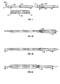
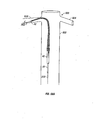
In another respect, the invention is a device for delivering an axially and radially
expandable woven body having two ends into an anatomical structure. The device
includes, but is not limited to, a first tube configured to accept a guide wire, and a second
tube configured to fit over the first tube. When the tubes are used for delivering the
axially and radially expandable woven body, one end of the axially and radially
expandable woven body is secured to the outside of the first tube and the other end of the
axially and radially expandable woven body is secured to the outside of the second tube.
The first tube may be made from NYLON or TEFLON. The second tube may be
made from NYLON or TEFLON. The device may also include, but is not limited to, a
guide wire configured to be placed within the first tube. The outer diameter of the first
tube may range in size from 3 French to 7 French. The outer diameter of the second tube
may range in size from 5 French to 9 French. The device may also include, but is not
limited to, a push-button release/lock mechanism configured to secure the first tube to the
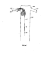
second tube. The device may also include, but is not limited to, an end fitting having a
side arm. The end fitting is configured to be secured to the first tube. The first tube may
be provided with at least one pair of first tube holes through which a first securing wire
may be threaded. The pair of first tube holes may be positioned proximate one end of the
first tube. The second tube may be provided with at least one pair of second tube holes
through which a second securing wire may be threaded. The pair of second tube holes
may be positioned proximate one end of the second tube.
In another respect, the invention is a device for delivering an axially and radially
expandable woven body having two ends into an anatomical structure. The device
includes, but is not limited to, a first tube configured to accept a guide wire. The first
tube has at least one pair of first tube holes that are positioned proximate one end of the
first tube. The device also includes, but is not limited to, a second tube configured to fit
over the first tube. The second tube has at least one pair of second tube holes that are
positioned proximate one end of the second tube. The device also includes, but is not
limited to, a first securing wire configured to be threaded through the pair of first tube
holes. The device also includes, but is not limited to, a second securing wire configured
to be threaded through the pair of second tube holes. When the tubes are used for
delivering the axially and radially expandable woven body, one end of the axially and
radially expandable woven body is secured to the outside of the first tube with the first
securing wire and the other end of the axially and radially expandable woven body is
secured to the outside of the second tube with the second securing wire.
In another respect, the invention is an occluding system that includes, but is not
limited to, a plurality of shape memory wires woven together to form a body useful for
occluding an anatomical structure. The body has first and second ends. Both ends of at
least one shape memory wire are located proximate one end of the body. The shape
memory wires cross each other to form a plurality of angles, at least one of the angles
being obtuse. The value of the obtuse angle is increased when the body is axially
compressed.
The shape memory wires may be made from nitinol. The occluding system may
also include, but is not limited to, an occluding agent enclosed within the body. The
occluding agent may include one or more threads of polyester. The occluding agent may
also include, but is not limited to, one or more threads of DACRON. The occluding
system may also include a jacket coupled to the body. The jacket may be made from
silicone. The jacket may be made from polyurethane. The occluding system may also
include, but is not limited to, a first tube configured to accept a guide wire, and a second
tube configured to fit over the first tube. Prior to delivering the body into an anatomical
structure, one end of the body is secured to the outside of the first tube and the other end
of the body is secured to the outside of the second tube.
One advantage of the present invention is the unique fixation method of the
tapered stent. The tapered shape of the stent allows the stent to be fixed in a tapered
vessel or tubular structure with less radial or expansile force than a straight stent might
exhibit, thus potentially resulting in a less hyperplastic intimal reaction.
The straight stent of the present invention exhibits a high expansile force and thus
a large capability of withstanding outer compression. This may be especially
advantageous in tumorous stenoses, or fibrous strictures (including radiation-induced
stenoses) where stents with inadequate expansile forces can be easily compressed and/or
are incapable of assuming their nominal shape and diameter. In some cases, even the
stenoses of arteriosclerotic origin can be so calcified (e.g., iliac or renal artery stenoses)
that extra radial force is required from the stent to hold the patency of the vessel.
Furthermore, the woven intravascular devices of the present invention are also able to
return to their original, unconstrained shape after being bent, even maximally.
Advantageously, the stents, occluders and filters of the present invention do not
possess free, sharp wire ends. Thus, many potential complications are eliminated
(Prahlow, 1997). Additionally, the tight mesh of the stents of the present invention
coupled with the use of nitinol wires, for example, makes them easy to monitor under
fluoroscopy.
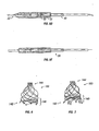
The present invention also includes a group of self-expanding, self-centering cava
filters woven from materials as described above such that a coherent element is formed
that without the use of a joint or attachment between the portions of the filters. The cava
filters of the present invention provide increased filtrating efficiency not only at the center
but also at the periphery of the cava. Additionally, the hourglass filter of the present
invention utilizes multiple filtration levels. The cava filters of the present invention are
able to self-center due to the symmetrical nature of their design and their potentially
flared base.
The cava filters of the present invention may utilize a relatively small, 7 French
delivery catheter or sheath. Additionally, the superb flexibility of the cava filters makes it
possible to deliver them via any of the possible access sites of the human body (femoral,
jugular, antecubital veins).
The present invention also includes a bi-iliac filter ("BI filter") that is a low-profile,
self-expanding, flexible, temporary filter which may be woven from a number of
superelastic or shape memory alloys. The BI filter is a type of temporary filter that can be
deployed from either femoral vein, and it can filtrate the blood at the iliac veins/inferior
cava junction. The BI filter of the present invention typically works at a low level of
venous circulation. Advantageously, the BI filter simultaneously filters all the blood
coming from both iliac veins, achieving almost 100% filtration. Further, the use of the BI
filter is particularly beneficial in perioperative and posttraumatic cases.
The inverse U-shape of the BI filter together with the expansile force of the
tubular weave ensures firm position along the iliac/cava junction. A further advantage of
the present invention is that the BI filter may utilize a relatively small, 7 French delivery
catheter or sheath. Further, due to the flexibility of the mesh of the BI filter, the delivery
system thereof may be advanced from ipsi- to contralateral iliac vein. As with the cava
filters, the BI filter may possess a non-ferromagnetic character making it MRI compatible.
The BI filter is suitable for temporary filtration. The BI filter allows for removal
of the entrapped thrombi safely and successfully before removal of the filter. Using an
adequately sized sheath, the small thrombus fragments entrapped within the mesh could
also be removed together with the filter.
The stents of the present invention can be advantageously covered with materials
such as silicone, polyurethane, and/or an anticancer coating agent that allow the stents to
reduce the possibility of restenosis after delivery, and which also allow the stents to be
used in stenting malignant stenoses, for example. The filters of the present invention may
also be covered with anticoagulant coating agents.
Ureter strictures/compression/occlusion may be stented with these uncovered
and/or covered stents; in particular, the use of a long tapered stent may advantageously
match the special conditions posed by the different caliber and distensibility of the
different segments of the ureter as well as the constant peristalsis.
The stents of the present invention can also be used in some non-vascular
applications including biliary tree and tracheo-bronchial system if the lesion does not
require a bifurcated stent.
The stents, occluders and filters of the present invention may be used in many
different applications. They provide the advantages of superb flexibility,
repositionability/removability, and precise positionability.
BRIEF DESCRIPTION OF THE DRAWINGS
The following drawings form part of the present specification and are included to
further demonstrate certain aspects of the present invention. The invention may be better
understood by reference to one or more of these drawings in combination with the
description of illustrative embodiments presented herein.
DESCRIPTION OF ILLUSTRATIVE EMBODIMENTS
1. Stents
Straight Stents
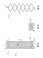
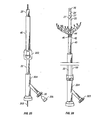
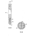
With reference to the illustrative embodiment shown in FIG. 1A, there is shown a
stent for insertion and delivery into an anatomical structure. The stent includes a plurality
of wires 5 which may be arranged in a plain weave so as to define an elastically
deformable body 10. As used herein, "elastically deformable" means that the
deformation of such a body is non-permanent and an original or initial shape may be
substantially recovered, or regained, upon the release of a force (which may be
mechanical, electromagnetic, or any other type of force). As used herein, "substantially
recovered" means that recovery need not be such that the exact, original shape be
regained. Rather, it means that some degree of plastic deformation may occur. In other
words, recovery need not be total. Such elastic deformability may be achieved by
utilizing the superelastic properties of suitable shape memory wires, which are discussed
below.
U.S. Patent No. 4,655,771 to Wallsten (1987)
displays the manner in which wires cross each other using
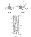
plain weave as shown in FIG. 1a therein. FIG. 2 also illustrates the manner in which the
wires 5 of the present intravascular devices may be arranged utilizing a plain weave.
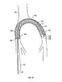
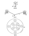
Body 10 is both radially and axially expandable. Body 10 includes front or distal
end 12 and rear or proximal end 2. As shown in FIG. 1A, end 12 has a plurality of closed
structures. These closed structures may be small closed loops 6 or bends 8 (FIG. 1B).
Both bends 8 and small closed loops 6 may be formed by bending a wire 5 at a selected
point located between the ends 7 of wire 5 (FIG. 1C shows small closed loops 6). For
most applications, the selected point of the bend or small closed loop may be close to the
midpoint of wire 5, as shown in FIG. 1C with respect to small closed loop 6. FIG. 1C
also shows both ends of wire 5 being located proximate end 2 of body 10 (although the
remainder of body 10 is not shown). Body 10 is formed by plain weaving wires 5, as will
be discussed below in greater detail.
Loops 6 and bends 8 provide significant advantages, some of which are
unexpected, over woven devices such as the WALLSTENT that have free wire ends. For
instance, the Wallsten patent recognizes that the free wire ends of the WALLSTENT
should be protected, implicitly acknowledging the potential tissue-damaging dangers such
free, sharp wire ends pose. The Wallsten patent suggests methods by which one can
attempt to lessen these dangers, such as connecting the free wire ends to each other by
attaching U-shaped members to them through heat welding, gluing or the like. These
suggested methods can be time-consuming and, as a result, expensive. No such steps
need to be taken in creating either loops 6 or bends 8 of the present woven devices as will
be discussed below in greater detail.
Further, the connections resulting from the methods disclosed in the Wallsten
patent are likely more prone to mechanical failure than are loops 6 or bends 8 of the
present woven devices. For example, welding can introduce anomalies such as cracks
(which may result from the non-uniform solidification, uneven boundaries, etc.); voids or
other irregularities resulting from porosity; inclusions (which include slag, oxides, etc.);
etc., into the welded metal that create stress concentrations and dramatically increases the
propensity for the welded connection to fail at those locations. In contrast, the gentle
curves and bends resulting in loops 6 and bends 8 are virtually free of any such induced
stresses and, as a result, are much less likely to fail.
The Wallsten patent also suggests gluing the free wire ends, a method that
provides even less structural integrity than can welding, because the resulting bond
between the joined wire ends is only as strong as the surface tension between the glue and
the metal used. Consequently, the joint created is more prone to failure than a welded
joint suffering from the anomalies just discussed.
Similarly, the Wallsten patent discloses first utilizing electric resistance heating to
weld together the points of crossing of the free wire ends in a ring around the stent and
then folding the free wire ends extending beyond the welded ring inwardly with light
plastic deformation through controlled heating. This method involves not only the likely
introduction of the anomalies discussed above that can result from welding, it also
involves an additional stress on the joints created as the free wire ends are folded
inwardly while being heated. Thus, this proferred joint is similar to the glued joint in that
it is likely even more prone to failure than one involving only welding.
In sum, the gentle curves and bends that may be used to create loops 6 and bends
8 of the present woven devices provide devices with safer ends: no free wire ends exist
that may unintentionally penetrate and damage the wall of the structure into which they
are delivered; the bends 8 or loops 6 are much less likely to mechanically fail than are the
free wire ends that are connected together using welding or glue; and the likely time-consuming
task of creating multiple welded or glued joints does not exist. Further, while
the closed structures 4 (discussed below in greater detail) may be reinforced using
methods similar to those suggested by the Wallsten patent (i.e., such as by welding), the
present woven devices have, at most, only half as many potential locations for using such
methods (and most likely less than half considering fewer wires are generally needed for
making the present stents than are needed for making comparably-sized WALLSTENTS,
even equating one of the present wires to two wires as those are used in the
WALLSTENT). As a result, the potential for mechanical failure of the present woven
devices is reduced accordingly.
In addition to the foregoing benefits, loops 6 and bends 8 also provide advantages
over the modified free wire ends disclosed in the Wallsten patent discussed above that are
unexpected. For example, the inventors have found that the mesh of one of the present
woven stents may be formed from fewer wires than can the mesh of a comparably-sized
WALLSTENT (even equating one of the present wires to two wires as those are used in
the WALLSTENT). Accordingly, the expansile force of one of the present woven stents
of a given size may be maintained with fewer wires than would be needed to maintain the
same expansile force of a WALLSTENT of the same size by simply increasing the mesh
tightness (i.e., by increasing angle a-FIG. 1A-discussed below in greater detail).
Similarly, the inventors have found that the same result may be achieved by increasing
the diameter of the present wires with or without adjusting the mesh tightness. As a
result, the amount of metal needed for the present woven stents may be less than what is
needed in another comparably-sized woven stent, such as the WALISTENT. This
reduction in necessary metal translates to a cost savings, and, as described above, also
means that patients are less likely to experience thrombosis and/or restenosis. As a
further result, the variety of sizes that may be created for the present stents and the variety
in the tightness of the weave of each is virtually unlimited, thereby facilitating virtually
all potential applications.
Further, the inventors also discovered that virtually no shortening occurs while
bending the present woven stents, nor do the diameters of the present woven stents
increase during bending. Thus, it is easier to accurately and predictably position the
present stents in a tortuous anatomy than it is to position other woven stents that shorten
more or suffer larger increases in diameter when bent, such as the WALLSTENT. For
example, a tightly-woven present stent, 2.5 cm long, 10 mm in diameter, formed from 10
0.006-inch wires may be maximally bent by simply holding the two ends thereof between
two fingers and bringing those ends together, and no shortening or diameter increase
occurs during maximal bending. In contrast, for a WALLSTENT formed from 24 0.005-inch
wires to behave similarly, the inventors found that it should be 6 cm long and 9 mm
in diameter; although, when manipulated in a similar manner, the WALLSTENT
experienced a 10% increase in diameter and some shortening. Thus, the length-to-diameter
ratios of the foregoing stents were 2.5 and 6.6, respectively.
As few as five wires, and an unlimited maximum number of wires may be used to
form body 10 for any given application. As used herein, "wires" will mean a strand
formed of any material, such as metal, plastic, fiber, etc. In an exemplary embodiment of
the present invention, 6 to 12 wires are typically used to form body 10 in most
applications.
The number of wires that may be used depends on the application, and specifically
on the desired expansile force of the stent. The expansile force of the stent is the radial
force necessary to reduce the diameter of the stent. Factors affecting the expansile force
of the stent include: the tightness of the weave (which is determined by the number of
wires used and the angle formed by the crossed wires - the more wires or the closer the
angle is to 180°, the tighter the weave), the number of wires used to form the woven stent,
and the diameter of the wires used. When body 10 is used in the coronary artery, for
example, it may be desirable to use the smallest possible amount of wire material to
prevent thrombosis and reduce the possibility of restenosis in the vessel with a relatively
slow circulation.
In
FIG. 1A, when
body 10 is in its initial, unconstrained shape, angle
a may range
from about 90° up to, but not including, 180°. The expansile force of
body 10 increases
as angle
a approaches 180°. It is to be understood that angles less than 90° may be
utilized for angle
a. In an exemplary embodiment, angle
a is preferably obtuse,
i.
e., more
than 90°, and most preferably about 150°. In certain applications, however, a larger
expansile force may be desirable, and, thus, angle
a may be closer to 180°, such as in the
case of a tumorous stricture or the like. In this regard, in an
in vitro comparative study, a
stent according to the present invention exhibited a higher expansile force and thus a
larger capability of withstanding outer compression than both a Z-stent and a
WALLSTENT of the same diameter, as revealed in Table 1, below. In Table 1, the
designation Δ in the leftmost column represents the circumferential displacement (in mm)
of the stent in question. For example, a Δ of 2 mm indicates that the circumference of the
stent in question was reduced by 2 mm, and the force necessary to effect that
displacement was then recorded. The designation "W" refers to the WALLSTENT.
| Comparison of Expansile Forces of a Z-Stent, a WALLSTENT and a Nitinol Woven Stent |
| Δ (mm) | Z Center | Z Between | Z Side by Side | W Center | W Overlap | W Side by Side | Woven Stent |
| 2 | 16 | 13 | 19 | 15 | 35 | 18 | 44 |
| 4 | 36 | 28 | 31 | 25 | 59 | 22 | 91 |
| 6 | 51 | 44 | 42 | 42 | 80 | 35 | 126 |
| 8 | 63 | 61 | 56 | 50 | 108 | 42 | 158 |
| 10 | 81 | 79 | 62 | 60 | 126 | 48 | 167 |
| 12 | 100 | 98 | 76 | 74 | 149 | 54 | 175 |
| 14 | 115 | 119 | 90 | 84 | 170 | 63 | 184 |
| 16 | 127 | 133 | 101 | 100 | 197 | 73 | 202 |
| 18 | 146 | 192 | 122 | 111 | 220 | 84 |
| 20 | 165 | unmeasur. | 142 | 129 | 248 | 96 |
With respect to Table 1, the unit "g" for "grams" is used as a measure of force.
Although the correct unit of force is the "dyne", which is equal to the mass in grams
multiplied by the gravitational constant, the inventors believe that the average reader will
have a better idea about the size of force when the associated mass unit (grams) is
specified.
When one uses, e.g., a WALLSTENT or other commercially available stent for
stenting, the manufacturer usually recommends to use a stent one mm larger than the
diameter of the vessel, after precise determination of the size of the vessel, to eliminate
the magnification factor caused by the fluoroscopy/radiography. This minimal
"overstenting" is used to achieve good contact between the stent and the vessel wall. The
manufacturer also typically provides exact data regarding the relationship between the
stent's diameter and length to facilitate precise positioning thereof. The woven nitinol
design of the present invention has significantly greater expansile force than that of the
WALLSTENT if a comparable number of wires are used to form the same caliber stent
(understanding that one wire as used herein would require the use
of two wires in the WALLSTENT, given the free, unclosed wires thereof). Compared to
the WALLSTENT, the closed structures of the stents of the present invention and the
better shape memory of the wires that may be used may result in a considerable reduction
in the size of the wires used, in the number of wires used, as well as in the angles between
the wires. For instance, in small vessel applications (e.g., coronary artery) it is
advantageous to use the minimum amount of wire (metal) to reduce the possibility of
thrombosis and/or restenosis. Furthermore, in preferred embodiments, angle a may be
reduced below 90 degrees without losing the necessary expansile force for self anchoring.
For the same vascular application, the same or even greater expansile force can be
achieved with a loosely-woven nitinol design of the present invention compared to the
WALLSTENT and other available stents. A stent of the present invention may also be
chosen so as to have a diameter approximately ten percent larger than the diameter of the
tubular structure to be stented.
Body 10 of a stent according to the present invention may be formed by various
methods of plain weave including hand weaving and machine weaving. The following
process is an exemplary embodiment of plain weaving according to the present invention.
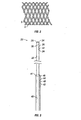
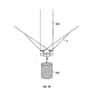
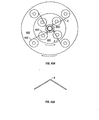
As shown in FIG. 16, a template 300 having a diameter corresponding to the chosen
diameter of body 10 is provided. The top of the template is equipped with holes 302
around its circumference. Pins 304 are placed through the holes such that they extend
beyond the outer surface of the template on opposing sides. As shown in FIG. 16, wires
5 are bent at about their midpoint around the pins. This bending may result in the
formation of bend 8 as shown, or wires 5 may be wrapped around the pins to form small
loops 6 (not shown). In one embodiment of body 10, angle b of small closed loop 6 or
bend 8 (FIG. 1A) may be less than 90°. In a more typical embodiment of body 10,
angle b may be equal to or greater than 90°, and may approach, but not include, 180°. In
an even more typical embodiment, angle b may be about 140-160°. As discussed above,
bends 8 and loops 6 are created in a manner that makes them likely more mechanically
sound than the joints disclosed in the Wallsten patent created by connecting two wire
ends together through welding or gluing.
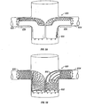
In one embodiment of the present plain weaving process, the ends of two wires 5
may be coupled together and placed around pin 304, instead of bending a single wire 5 as
above described. This coupling may be achieved by using any suitable means capable of
preventing the wires from returning to their straight, unbent configuration. As shown in
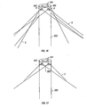
FIG. 30A, such means include bending and crimping a metal clip around the wires. In
another embodiment of the present plain weaving process, as shown in FIG. 30B, two
wires 5 may each be wrapped around pin 304 separately and secured using any suitable
means, such as those just described, in further contrast to bending one wire around pin
304. After annealing (i.e., heating and cooling) wires 5 shown in FIG. 30B as described
below, the two wires may be coupled to each other using any suitable means such as
twisting, crimping or tying as further below described.
Although only two pins are shown in FIG. 16, it is to be understood that this is
done for illustrative purposes only, and not to indicate the appropriate number of wires to
use in any given application. In an exemplary embodiment, template 300 is typically
formed of brass or copper, but may be formed of any suitable material capable of
withstanding the cure temperature below discussed, such as stainless steel. Similarly, in
an exemplary embodiment, pins 304 are typically formed of stainless steel, but may be
formed of any similarly suitable material. It is to be understood that the pins may be
supported by the template by any suitable means capable of withstanding the cure
temperature, including preforming, attachment by welding, threading, or the like.
As shown in FIG. 17, after the wires have been bent around the pins, the wires are
secured to the template to prevent them from returning to their original, straight, unbent
position. This may be necessary given the superelastic nature of wires such as nitinol and
the like (discussed below). As shown in FIG. 17, wires 5 are secured by securing wire
306 around the outside of wires 5 so as to secure wires 5 against the outside of the
template. In an exemplary embodiment, copper is typically used for securing wire 306,
but it is to be understood that any suitable wire capable of withstanding the annealing
temperature of about 500°C discussed below may be used. After the wires are secured,
small weights 360 (shown in FIG. 20) are attached to the free ends of the wires using any
suitable means such as tying, or the like. In an exemplary embodiment, weights with
masses of approximately 50-100 grams may typically be used with wires having
diameters of between about 0.005 inches and about 0.011 inches. However, it is to be
understood that weights of different masses may be chosen so long as the wires are kept
under tension (i.e. straight) during plain weaving (as described below), and properly
balance the central weight (described below).
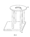
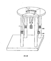
As shown in FIG. 18, a stand 330 with a circular plate 320 is provided with an
opening 325. The diameter of the opening may depend on the diameter of the template.
In an exemplary embodiment, an opening with a diameter of about 4.5 cm may be
typically utilized in conjunction with a template of about 1.0 cm. It is to be understood,
however, that an opening with a diameter more closely corresponding to the diameter of
the template may be utilized.
As shown in FIG. 19, before or after the weights are attached to the ends of wires
5, the template is inverted. In an exemplary embodiment, the weights may be typically
attached to the free ends of the wires prior to inversion of the template such that the wires
are kept under tension and may be prevented from returning to their unbent, nominal
state. A central weight 340 may then be attached to the end of the template. In an
exemplary embodiment, the central weight may be typically hung from the pins.
However, it is to be understood that the central weight may be attached to the template's
end in any suitable manner, such as hanging from holes in the template itself, etc.
Before or after central weight 340 is attached to the end of the template, the
inverted template is placed through opening 325, as shown in FIG. 20. In an exemplary
embodiment, the central weight may typically be attached to the inverted template after
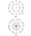
the inverted template is placed through opening 325. As shown in FIG. 20, the wires 5
may be arranged fairly evenly around the circumference of the circular plate. As shown
in FIG. 21, in an exemplary embodiment of the present invention, 6 wires having 12 ends
numbered 1-12 (each wire having 2 ends) are shown as being arranged in a substantially
symmetrical fashion around circular plate 320. The weights 340 and 360 typically serve
to keep the wires under tension and in balance. Next, the plain weaving may take place.
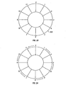
In the manner shown in FIG. 22, the weave may be started by crossing one wire
end over the adjacent wire end. This crossing may be made in either a clockwise or
counterclockwise fashion. This crossing may be carried out as directed by the arrows
shown in FIG. 22. After a complete set of crosses (or one "turn") has been carried out,
the location of the crossed wire ends is as shown in FIG. 23. In an exemplary
embodiment, the resulting location of the wire ends may be achieved by crossing one wire
end over another in one direction while slightly shifting the wire end not crossed in the
opposite direction. In an exemplary embodiment, this shifting may be about 15°. Thus,
wire end 1 may be crossed in a clockwise direction over wire end 2, while shifting wire
end 2 about 15° counterclockwise. Once one turn has taken place, crossing may begin in
the same fashion, but in the opposite direction, as shown in FIG. 24. This process may
be repeated until the plain weave is complete.
The tightness of the plain weave (i.e., the angle a between the wires - FIG. 1A)
may be adjusted by changing the central weight. An increase in the central weight results
in a looser weave (decreased angle a between the wires) and vice versa. Upon
completion of the plain weave, the adjacent wire ends may be closed as below described.
In an exemplary embodiment according to the present invention, a conventional
braiding machine may be utilized to arrange wires 5 in a plain weave to form body 10 of a
stent or any other device described herein. Such a braiding machine may be obtained, for
example, from Wardwell Braiding Machine Company in Central Falls, RI. The manner
in which a plain weave may be achieved using a conventional braiding machine is
displayed in FIG. 7 of U.S. Patent No. 5,419,231 to Earle, III et al. (1995),
as well as in FIG. 1 of U.S. Patent No.
5,485,774 to Osborne (1996).
After the plain weave process is complete, as shown in FIG. 1A, at the rear or
proximal end 2 (the end closest to the surgeon/operator) of body 10, wire ends 7 may be
twisted together using multiple twists so as to form closed structures 4. In an exemplary
embodiment, as few as 2 twists may be used, and as many as about 6. In an exemplary
embodiment, it is preferable to keep the twisted wire ends as short as possible. The
shorter the twisted wire ends are kept, the more resistant to bending the twisted wire ends
are. As a result, the twisted wire ends are less likely to be inadvertently displaced during
placement, repositioning, or retrieval, thus reducing the potential for causing tissue
damage. Although not shown, it will be understood to those of ordinary skill in the art
with the benefit of the present disclosure that the wire ends may be coupled together,
instead of by twisting, using any suitable means capable of withstanding the heating
described below, such as bending and crimping a metal clip around the wires, tying them
together with suitable material such as stainless steel wire, welding, etc.
Other configurations of template 300 may also be utilized consistently with the
present disclosure. For example, template 300 may be provided not only with pins 304 or
tabs 600 (described below), around which wires 5 are bent, wrapped, tied, twisted, etc.,
prior to weaving the body of the stent (or the bodies of any of the woven structures
disclosed herein), but may also be provided with pins around which the wire ends may be
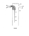
twisted in fashioning closed structures 4. Finish pins 800 may be supplied on a ring, such
as ring 802 depicted in FIG. 48, in any suitable fashion, including, for example, through
removable or permanent attachment. Ring 802 may be configured to threadably engage
template 300 as depicted in FIG. 48. In other embodiments, ring 802 may be configured
to engage template 300 by virtue of frictional forces (not shown) or may be configured to
be secured to template 300 as would a clamp (not shown). Finish pins 800 may also be
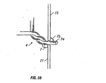
engaged with template 300 in the same manner as pins 304. As shown in FIG. 49, in
such an embodiment, template 300 may be provided with finish holes 804 similar to holes
302, and finish pins 800 may be placed through finish holes 804. Ring 802 may also be
utilized in place of holes 302 and pins 304.
In an embodiment in which finish pins 800 are engaged with template 300 through
the utilization of ring 802, the number of finish pins utilized may be equal to the number
of wires 5 that are used. Template 300 may be threaded along any portion of its length so
as to best accommodate a variety of woven body sizes. For example, only a portion of
template 300 may be threaded, as depicted in FIG. 49. Threads need not be utilized with
a ring that engages template 300 by virtue of frictional forces.
Advantageously, the use of ring 802 allows for the easy and precise alignment of
pins 304 or tabs 600 with finish pins 800. Another advantage afforded by the use of ring
802 is the ease with which the precise length of the woven body may be achieved. The
length of the woven body may be achieved by adjusting and fixing the distance along the
length of template 300 between pins 304 or tabs 600 and finish pins 800. In an
embodiment in which finish pins 800 are placed through finish holes 804, the number of
finish pins utilized may be equal to one-half of the number of wires 5 that are used, since
both ends of the finish pins will be utilized. Template 300 may be provided with finish
holes 804 along any portion of its length so as to best accommodate a variety of woven
body sizes. For example, only a portion of template 300 may be provided with finish
holes 804, as depicted in FIG. 49.
As with ring 802, the use of finish holes 804 advantageously allows for the easy
and precise alignment of pins 304 or tabs 600 with finish pins 800. Additionally, the
precise length of the woven body may advantageously be achieved by virtue of the
distance along the length of template 300 between pins 304 or tabs 600 and finish holes
804 (and, therefore, finish pins 800.)
With finish pins 800 in place, once the wire ends of wire(s) 5 have been woven
around template 300, the wire ends may be secured around finish pins 800 in any suitable
manner to form closed structures 4, including by twisting, bending, wrapping and the like.
In one embodiment, the wire ends may be crossed, then bent around finish pins 800 and
then secured together using a short piece of a thin-walled metal tubing. Such a joint may
then be reinforced by soldering, welding, or the like. A suitable number of additional
twists may be utilized after securing the wire ends around finish pins 800 in forming
closed structures 4. Securing wire 306 (not shown) may be utilized to secure closed
structures 4 to template 300 during annealing.
As a result of securing the wire ends around finish pins 800, the angle created
between the crossed wire ends may be similar, if not identical to, angle b described
above. Advantageously, by using finish pins 800, this angle between the crossed wire
ends may be maintained, preventing the weave of the woven body from loosening. Were
loosening to occur, the expansile or radial force of the portion of the body with the
loosened weave could decrease, causing that portion of the woven body to remain
elongated within the structure in which it is placed. Therefore, through the use of finish
pins 800 and as a result of the correlating maintenance of the angle between the crossed
wire ends that are wrapped or twisted around the finish pins, the tightness of the weave
along the length of the woven body - from end to end - may be consistent and resistant to
loosening, and the expansile force of the end of the woven body having closed structures
4 may be comparable to the expansile force of the other portions of the woven body.
Another method of creating body 10 of a stent according to the present invention
is illustrated in FIGS. 37-47B. As shown in FIG. 37, the base of template 300 may be
equipped with longitudinal tabs 600 formed by two longitudinal cuts connected by a
transverse cut. The length of the cuts may be determined based upon the size of the
template chosen. For example, a template that is about 10 mm in diameter may have
longitudinal tabs with longitudinal cuts about 4 to 5 mm long, and the connecting
transverse cuts may be about 2 mm long. As illustrated in FIGS. 37, tabs 600 may be
slightly elevated from the surface of template 300 and may be positioned equally around
template 300.
FIGS. 37 and 38A and B also illustrate that wires 5 may be bent around tabs 600
at selected points located between the ends of the wires to form bent portions along wires
5. The bent portions may take the form of bends 8, as shown in FIG. 38A, or may be
further wrapped around tabs 600 to form loops 6, as shown in FIG. 38B. Angle b of
bends 8 or loops 6 may be less than 90°. In a more typical embodiment of body 10, angle
b may be equal to or greater than 90°, and may approach but not include, 180°. The bent
portions may be arranged to define end 12 of body 10. Wire ends 7 of wires 5 may then
be weaved to create body 10 using, for example, the following machine weave method.
As shown in FIG. 39, ends 7 of each wire 5 may be arranged around a pair of
bobbins 602. The length of the wire wound around each bobbin may be determined by
considering the total length of the wire needed to form body 10 as well as the wire length
needed to arrange the bobbins around weaving plates (shown in FIG. 40), which are
discussed below in greater detail.
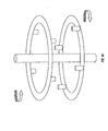
As shown in FIG. 40, in one embodiment in which bobbins 602 are utilized, two
coaxially arranged weaving plates may be utilized. As shown in FIG. 41, upper weaving
plate 604 and lower weaving plate 606 may be positioned in different horizontal planes.
FIG. 41 illustrates that the weaving plates may be equipped with multiple bobbin rods
608, the axes of which are substantially perpendicular to the weaving plates, on which
bobbins 602 may be slidably secured. (FIG. 41 depicts only 4 bobbins for the sake of
simplicity.) The weaving plates may be provided with holes therein through which
template 300 and/or wires 5 may pass, as shown in FIG.41. Template 300 may be
secured to the base of the weaving machine chosen using any suitable means such as
template rod 610, around which template 300 may pass, as shown in FIG. 41. Template
300 may be secured to the base of the weaving machine chosen using any suitable means
such as template rod 610, around which template 300 may be slidably placed (FIG. 35).
Template rod 610 may be configured to firmly engage template 300 through frictional
forces (e.g., by tapering template rod 610). Instead of template rod 610, any appropriate
lock mechanism may be used to secure the base of the weaving machine to template 300.
As shown in FIGS. 42A and 43A, the pairs of bobbins 602 may be prepared for
weaving by arranging one bobbin on upper weaving plate 604 and the other bobbin from
the pair on lower weaving plate 606. Wires 5 may then be bent around tabs 600, and the
ends of the wires may be attached to bobbins 602 using any suitable means capable of
holding wires 5 under tension throughout the weaving process. An example of such a
mechanism is a one-way brake that allows bobbin 602 to rotate in a single direction only,
such that the wire 5 may wind off bobbin 602. Simultaneously, such a brake may be
configured so as to continuously maintain tension in wire 5 by virtue of the brake's
resistance to the winding off of wire 5.
As shown in FIG. 42A, with the wire ends in place, the weaving may begin by
crossing the wire ends of the same wire, which results in the formation of a small caliber
loop 6 (FIG. 42B) at the site of the bent portion. In another manner of weaving
illustrated in FIG. 43, the wire ends of different wires may be crossed first, resulting in
bend 8 at the site of the bent portion (FIG. 43B).
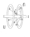
As shown in FIGS. 44-45, the two weaving plates may be arranged such that the
surfaces thereof from which the bobbin rods extend face each other. In this alternative
embodiment, the diameters of the plates may be the same or different. Wires 5 may be
arranged on bobbins 602 in the same manner as described above, as shown in FIG. 45.
Despite which of the aforementioned weaving plate arrangements is utilized, the
weaving plates rotate in opposite directions during the weaving process. The weaving
plates may be operated at any suitable speed. In this regard, a speed as low as 1 to 10
cycles per minute is acceptable. The weaving plates may also be driven by hand.
The weaving plates may supported and rotated using any suitable means. FIG. 61
illustrates one means of supporting and rotating weaving plates 604 and 606. (FIG. 61
depicts on 4 bobbins for the sake of simplicity.) As shown, weaving plate supporter 650
may be equipped with lower arm 652 and upper arm 654 for supporting lower and upper
weaving plates 606 and 604, respectively. Weaving plate drivers 660 may be secured to
the upper and lower arms of the weaving plate supporter and engaged with the weaving
plates in order to operate them. The drivers may be configured to operate in any suitable
fashion. For example, the drivers may be configured with a power source and provided
with gears of any suitable configuration for causing the weaving plates to rotate. The
drivers may also be configured to utilize magnetism or electromagnetism to rotate the
weaving plates. The drivers may be also be configured such that the weaving plates may
be rotated by hand. Further, although not shown, it will be understood to those of skill in
the art, with the benefit of this disclosure, that either or both of the upper and lower arms
may be provided with branches to which drivers may be attached. The drivers on the
branches could then be secured to or engaged with the top surfaces of the weaving plates
in the same fashion that drivers 660 are engaged with the bottom surfaces of the weaving
plates as shown in FIG. 61. Thus, in such an embodiment, both the top and bottom
surfaces of each weaving plate would be engaged with drivers.
A braiding machine suitable for carrying the weaving process just described (i.e.,
utilizing the weaving plates) may be obtained, for example, from Wardwell Braiding
Machine Company in Central Falls, RI.
After the weaving process is complete, wire ends 7 may be twisted together or
coupled as described above to form closed structures 4. To make the process of wire
twisting faster and easier, the wires may be twisted with a special hand tool designed for
this purpose. Tool 612 illustrated in FIG. 46A follows the principle of an automatic
pencil. Jaws 614 of tool 612 are configured so that wire ends 7 may be firmly held
between jaws 614. Jaws 614 may be activated by push button 616 moving against spring
618. After placing wire ends 7 into pre-formed gaps 620 located between jaws 614 (FIG.
46B), spring 618 expands (or returns to its unconstrained state) and retracts jaws 614,
securing wire ends 7 firmly between jaws 614 due to the pressure of outer housing 622
acting to close jaws 614. Outer housing 622 may then be rotated to create multiple twists
of wire ends 7. As illustrated in FIGS. 47A and 47B, the twisted ends of body 10 may be
secured to template 300 using transverse tabs 624, which may be formed the same way as
longitudinal tabs 600.
After the plain weave of wires 5 is completed on the template, if the wires are
made of a material that can be programmed with either thermal shape memory or
superelasticity such as nitinol or other shape memory materials described below, body
10/template unit may be heated so as to program body 10 with either thermal shape
memory or superelasticity. If body 10 is programmed with superelasticity, its initial
shape can be deformed by applying a force thereto. After removal of the force, body 10
may substantially recover its initial shape. If body 10 is programmed with thermal shape
memory, its initial shape can be deformed upon application of a force at a first
temperature. The force may be removed, and body 10 may remain deformed until heated
to a second temperature. At the second temperature, body 10 may substantially recover
its initial shape.
In programming body 10 with superelasticity, the body 10/template unit may be
heated to about 500°C for about 5 to 15 minutes, typically about 12 to 15 minutes, and
even more typically for about 15 minutes, in an oven. After allowing the unit to cool to
room temperature, wires 5 possess superelastic properties. In an exemplary embodiment,
natural cooling is typically used. It is to be understood, however, that accelerated cooling
using a fluid bath, for example, may be utilized resulting in slightly different superelastic
characteristics than are achieved with natural cooling. In programming body 10 with
thermal shape memory, the body 10/template unit may be heated to about 500°C for
about 60 to 120 minutes, typically about 120 minutes, in an oven. After allowing the unit
to cool to room temperature, wires 5 possess thermal shape memory. In an exemplary
embodiment, natural cooling is typically used. It is to be understood, however, that
accelerated cooling using a fluid bath, for example, may be utilized resulting in slightly
different thermal shape memory characteristics than are achieved with natural cooling.
In an exemplary embodiment of body 10, it is preferable to further reinforce the
coupled wire ends of closed structures 4 after body 10 has been properly annealed
(especially if twisting was utilized). This reinforcement may be accomplished by any
suitable means such as point welding, soldering, pressure welding, or the like. The wire
ends of closed structures 4 may be soldered by removing any oxide layer that may have
formed over the relevant portions of the wires used, and applying solder to those portions.
Soldering may be enhanced by first wrapping the coupled wire ends of the closed
structures 4 with thin stainless steel wires. In an exemplary embodiment, point welding is
preferred to soldering, because point welding is easier to perform than soldering, and may
be more suitable with regard to long-term implantation of the stent.
The wires of body 10 may be constructed of any material compatible with the
tissue in which the stent will be placed. Further, the material may be suitably rigid and
elastic and capable of being programmed with either superelasticity or thermal shape
memory. The materials may, for example, be NiTi alloys like nitinol. Such alloys can be
heated and allowed to cool to room temperature, resulting in the alloys having either
superelastic or thermal shape memory properties, depending on the heating time as above
described. Other alloys that may be used include FePt, FePd, and FeNiCoTi. These
alloys may be heat treated to exhibit thermoelastic martensitic transformation, and,
therefore, good thermal shape memory. Other alloys such as FeNiC, FeMnSi, and
FeMnSiCrNi do not possess long-range order and undergo nonthermoelastic
transformation, and, thus, may also be used. Additionally, some β-Ti alloys and iron-based
alloys may also be used.
In an exemplary embodiment, nitinol possessing about 55 to 56 % Nickel, and 45
to 44 % Titanium, may be used for wires 5 of body 10. Such nitinol wires are
commercially available from Shape Memory Applications in Santa Clara, CA.
When using nitinol wire, the radiopacity of body 10 advantageously increases
over the radiopacity of stents formed using materials such as stainless steel. The
radiopacity depends primarily on the diameter of the nitinol wires and the tightness of the
plain weave created by the wires. The radiopacity of body 10 can be increased further by
using silver solder to reinforce the coupled wire ends forming closed structures 4.
The wire sizes that may be used for the stents of the present invention vary
depending on the application of the stent. In an exemplary embodiment, small stents
ranging from about 2 to about 4 mm in diameter and about 1 to about 2.5 cm in length,
typically for coronary application, may utilize wires from about 0.003 to about 0.006
inches in diameter. In an exemplary embodiment, medium stents ranging from about 4.5
to about 10 mm in diameter and about 2 to about 10 cm in length, such as are used in the
iliac artery, femoro-popliteal artery, carotid artery, and the renal artery, may utilize wires
from about 0.006 to about 0.009 inches in diameter. In an exemplary embodiment, large
stents above about 10 mm in diameter may utilize wires from about 0.006 to about 0.012
inches in diameter. Applications for the large stents include the aorta (typically a vessel
diameter in about the 20 to 40 mm range), the inferior vena cava ("IVC"), which is
usually less than about 28 mm in diameter, the superior vena cava ("SVC"), the
esophageal (20-25 mm in diameter), and the colon, which may be about 15 to about
25 mm.
Tapered Stents
With reference to the illustrative embodiment shown in FIG. 14, there is shown a
tapered stent for insertion and delivery into an anatomical structure. Tapered body 100
may be formed using plain weave by the methods above described. Potential
embodiments of tapered body 100 include the single wire embodiment. The types of
applications for which a tapered stent may be used include the ilio-femoral, femoro-popliteal
arteries, as well as in the carotid arteries for stenting long lesions.
The tapered configuration may be achieved different ways. In a first method using
the hand weave method or any of the machine methods described above, a template may
be chosen possessing an appropriate taper. In an exemplary embodiment, a template with
a smooth, contiguously decreasing diameter without steps is typically used. The shape of
the template may correspond roughly to the inner shape of the tapered stent. The shape of
the tapered stent may be chosen based on the shape of the vessel or structure into which it
will be placed.
In an exemplary embodiment, it may be preferable to choose a shape for the
tapered stent (and, thus, for the template) such that a "wedge-effect" will be achieved
between the tapered stent and the vessel or structure into which it is placed. The wedge-effect
may be used to fix the stent in position and prevent it from distal migration. It is to
be understood, however, that any suitable means for improving the fixation of the stent in
the vessel or structure, such as flaring the proximal end of the stent, may be used in
addition to or instead of the wedge-effect.
Using such a template and either hand or machine weave, the weave may be
substantially uniform along the axial length of the stent. As a result of the substantially
uniform weave, the expansile force of the stent may be substantially uniform along the
axial length of the stent. Although the expansile force may be substantially uniform as
stated, the match between the diameters of the tapered stent and the vessel into which the
stent is placed may result in the vessel being exposed to a force lesser than would be
exhibited by a straight stent.
In another embodiment according to the present invention, a template possessing a
uniform diameter as described above may be chosen for use with either the hand weave
method or a machine method. The diameter of this template may correspond to the
diameter of the largest portion of the stent. Tapered body 100 may be woven around this
template and heated and cooled as above described. The wire ends of closed structures
104 may then be reinforced as needed for the application. Tapered body 100 may then be
mounted on a tapered template in a fashion similar to the one described above (e.g., using
a copper wire), and reheated in a manner similar to the original heating. Forming the
stent in this manner results in a contiguously loosening mesh toward the tapered end of
the stent. That is, angle a is contiguously decreased toward the distal end 102 of tapered
body 100 resulting in a decreasing expansile force of the tapered stent towards the tapered
distal end 102.
It is to be understood that if a stent (or any other device disclosed herein) is
remodeled a number of times and it is not intended that the stent be programmed with
thermal shape memory, care should be taken not to exceed a total heating time (which
includes the first heating time and the second heating time, etc.) of about 60 minutes,
because at about 60 minutes, the stent may be programmed with thermal shape memory.
As with body 10, one or more of the coupled wire ends of tapered body 100 may
be left slightly longer than the others and bent inward so as to allow for retrieval of the
stent using a foreign body retrieval device. Further, closed structures 104 of body 100
may be flared to improve stent fixation.
In an
in vitro study, the expansile force of the tapered stent of the present
invention was found to be proportional to the weave tightness. The results of this study
are set forth below in Table 2. The tightness of the weave is strongly associated with the
angle between the crossing wires as well as with the number of wires used for creating the
weave. The stents used in the study were built from 0.011 inch nitinol wires. If the
angles between the crossing wires are wide (closer to 180°), the stent is better able to
withstand any outer compression. An increase in the diameter of the nitinol wire would
increase the expansile force of the stent.
| Taper-Shaped Self-Expanding Repositionable Stent Comparative Study, Using 0.011" Diameter Wires |
| Δ (mm) | 10 Wires, Tight Weave | 8 Wires, Moderate Weave | 6 Wires, Loose Weave | 6 Wires, Tight Weave |
| 2 | 115 | 91 | 26 | 92 |
| 4 | 176 | 123 | 55 | 103 |
| 6 | 208 | 141 | 74 | 119 |
| 8 | 238 | 158 | 92 | 126 |
| 10 | 273 | 170 | 103 | 136 |
| 12 | 293 | 186 | 120 | 145 |
| 14 | 331 | 202 | 129 | 153 |
| 16 | 371 | 223 | 146 | 171 |
With respect to Table 2, the inventors used the unit "g" for "grams" as the
measure of force for the reasons discussed above. Similarly, the designation Δ in the
leftmost column of Table 2 represents the circumferential displacement (in mm) of the
stent in question. For example, a Δ of 2 mm indicates that the circumference of the stent
in question was reduced by 2 mm, and the force necessary to effect that displacement was
then recorded.
Advantages of the tapered stent of the present invention include superb flexibility,
repositionability and removability, precise positionability, and better matching than a
cylindrical stent with a uniform diameter between the tapered vessel and the stent which
may result in less intimal reaction and longer vessel patency.
Covered Stents
Various material may be suitably used as grafts (including materials used as
covers and those used as liners) that may be attached to the present woven stents so as to
create stent grafts. One type of covering material that may be utilized for this purpose is
made from material that is stretchable enough to substantially follow the movement of the
stent's mesh. This type of graft material includes woven polyester, Dacron, polyurethane
and the like. Depending on the application, the graft material may, for example, be
somewhat porous (to facilitate endothelial ingrowth), highly porous (to leave bridged side
branches patent) or non-porous (e.g., to exclude an aneurysm or fistula from circulation,
or in another application to prevent tumor ingrowth into the stent graft lumen).
The graft material may be attached to either the outer or the inner surface of the
stent, so as to serve as a cover or a liner, respectively. The graft material may be attached
to the stent using monofilament sutures (e.g., polypropylene such as 5-0, 6-0, 7-0 Prolene,
which is commercially available from Ethicon), glue, heat, or any other appropriate
means.
Graft materials that are not stretchable or elastic may also be utilized to form stent
grafts. One such material is PTFE. Such graft material may be attached to only one of
the stent end's, thereby allowing free movement of the wire mesh. The attachment
between the stent and the graft material may be created at the proximal end of the
resulting stent graft (that is, the end of the stent that will be closest to the operator).
Such a stent graft may be pre-loaded into an appropriately-sized sheath. The graft
material may be folded or arranged so that it occupies as little space within the sheath as
possible.
Delivering a stent graft having a graft material made from a relatively non-stretchable
material such as PTFE may be performed in a manner that is different than the
manner in which a stent graft having a stretchable graft material may be delivered. For
example, with a stent graft having a cover made from relatively non-stretchable graft
material, after the stent graft is positioned as described below in greater detail, the sheath
may be retracted and the graft material may thereby be exposed. Then the stent may be
allowed to assume its unconstrained diameter by using the coaxial delivery system. The
fact, that the coaxial delivery system enables to achieve a more compressed mesh
tightness than that achievable by allowing the stent to recover, may be advantageous to
create an adequate contact between both the stent and the graft as well as between the
stent graft and the vessel wall. The different delivery mechanism requires a different
approach to stent graft retrieval. First, the stent is completely restretched over the
delivery tubes and the stent's completely elongated position is secured by the proximal
lock mechanism. Second, the sheath is advanced preferably using some rotating
movement to recapture the graft material. The creation of the attachment site between the
stent and the graft at the proximal end of the stent is advantageous for possible
repositioning. The stent's proximal end is secured to the outer delivery tubes, and the
graft to the proximal end of the stent, therefore, the proximal portion of the graft is
formed into a funnel shape facilitating its retrieval into the sheath.
Side-By-Side Stent Placement in Aorta and Bilateral Renal Artery
The present stents may be delivered in a variety of anatomical structures. Further,
they may be used in conjunction with each other in a variety of manners to best treat the
diseased structure. For example, as shown in FIG. 54, the bilateral aorto-renal junction
830, consisting of aorta 832, left renal artery 834 and right renal artery 836, along with
the aorto-iliac junction 840, consisting of left iliac artery 842 and right iliac artery 844,
may be treated using uses two stents positioned in side-by-side relationship with each
other. Alternatively, stent grafts shorter in length than those shown in FIG. 54 may be
delivered within the aorta or the aorto-iliac junctions with some overlap therebetween.
The stents that may be utilized may be woven and annealed as described above on
a variety of templates. In one embodiment, straight templates may be used. The stents
may also be woven and annealed as described above so as to be relatively tapered, such as
those in FIG. 54. In such a configuration, the portions of the stents that will occupy the
aorta may be larger in caliber than those portions of the stents that will occupy the renal
arteries. The stents may also be woven on templates that are configured with a bend that
may approximate or match the angle between the appropriate renal artery and the aorta.
Stents that may be partially or completely provided (i.e., covered or lined) with
any of the graft materials described above using any of the methods of connection
described above may be used in this application. In the embodiment of the pair of stents
illustrated in FIG. 55, the portions of the stents that occupy aorta 832 and portions of the
stents proximate the caudad surfaces 838 of renal arteries 834 and 836 are covered. By
only partially covering the portions of the stents that will occupy renal arteries 834 and
836, the possibility of endoleak from the renal arteries may be greatly reduced or
eliminated.
In another possible embodiment suitable for this application illustrated in FIG.
56, the aorto-renal stent may include struts 850 that may be formed by twisting
neighboring segments of wires 5 during the weaving process. Struts 850 may also be
formed in any suitable manner such as by encasing neighboring segments of wires 5 in
flexible tubes, such as those made of nitinol, or by soldering or welding neighboring
segments of wires 5 together, etc. As used herein, "struts" means segments of wires that
are joined together in any suitable manner such as twisting, encasing within a sufficiently
flexible piece of tubing, soldering, welding, etc., such that the portion of the stent formed
from the struts is less disruptive of the blood flow therethrough than would be the same
portion formed from a weave. The stent graft having struts 850 may, like the stent grafts
depicted in FIG. 55, be covered partially with any suitable graft material, such as those
relatively stretchable materials disclosed above. Accordingly, the portions surrounding
struts 850 may be covered while leaving struts 850 uncovered and therefore arranged so
that when delivered as shown in FIG. 56, struts 850 are advantageously positioned within
the vasculature with regard to hemodynamics. The use of struts 850 in this fashion may
be advantageous in comparison to leaving a similar portion of the stent utilized simply
bare, as in FIG. 55, in that struts 850 would be less likely to create turbulence in the
blood flow.
In one embodiment of the stent graft illustrated in FIG. 56 having struts 850,
different portions of the stent may be provided with different numbers of wires. Turning
to such a stent, the weave may begin at the end of the stent that will be placed in the renal
artery and made be made from n wires. The portion of the stent occupied by struts 850
may also be made from n wires. The larger portion of the stent that will occupy the aorta
may use n + x wires, where x denotes the number of additional wires utilized, and may be
between 1 and 2 n . Preferably, x is selected from an integer between 2 and n, and more
preferably x equals n. The template on which this type of stent is formed may have pins
304 positioned, for example, at locations proximate the end and beginning of struts 850.
Biodegradable Devices
Both the straight and the tapered stents of the present invention (as well as the
filters and occluders discussed below), except for the single wire embodiments of these
devices, may be formed with filaments made of biodegradable material so as to form self-expanding,
bioabsorbable, biodegradable stents that may, in addition to functioning as
stents, function as drug or nutrient delivery systems as a result of the material used.
Many factors may be considered in choosing materials from which to form the
biodegradable stents of the present invention. In one embodiment, the biodegradable
stents of the present invention may be formed from materials of minimal thickness so as
to minimize blood flow blockage and facilitate bioabsorbtion. In another embodiment,
the material may be chosen so as to exhibit sufficient radial strength to allow the body
formed to function as a stent. The material from which the biodegradable stents may be
formed may also degrade within the bloodstream over a period of weeks or months, so as
not to form emboli. The material may be chosen such that the stent does not degrade
before an endothelial layer forms in the stented vessel or structure in cases in which
stenosed aortoiliac arteries with lengthy affected segments are treated. The material
chosen may be chosen to be compatible with surrounding tissue in the vessel as well as
with blood.
The body of a biodegradable stent may be formed by plain weave using the
methods above described. The size of the filaments used may vary according to the
application. In some embodiments, the filaments may be reduced in size in comparison
to the size of wires used in comparable applications involving non-biodegradable devices.
In other embodiments, the number of filaments used may be increased in comparison to
the number of wires used in comparable applications involving non-biodegradable
devices.
The minimum number of filaments that may be used to create the body of a
biodegradable device (including stents, occluders and filters) may be about 5. In one
embodiment, 12 filaments may be used. With regard to stents, in creating the body using
plain weave, the angle of the crossed filaments (described above as angle a) may vary as
described above, but is typically 150-160°. In one embodiment, the angle of the crossed
filaments may be as large as possible to achieve the largest radial force possible and
further ensure that the stent may have enough expansile force to remain in place after
being delivered. The filament ends, after plain weaving is complete, may be coupled
together to form closed structures using any suitable means such as by heat treatment or
sealing, gluing, tying, twisting, crimping, taping, or the like. In another embodiment, a
long body may be woven, and the body may be cut into tubular segments. Closed
structures may be formed at both ends of the segmented bodies by coupling the filament
ends together as above described.
In one embodiment, the filaments used may be made of polyglycolic acid
("PGA"), poly-L-lactic acid ("L-PLA"), polyorthoesters, polyanhydrides,
polyiminocarbonates, or inorganic phosphates. These polymers are commercially
available from United States Surgical Corporation, Norwalk, CT; Birmingham Polymers,
Inc., Birmingham, AL; and Ethicon, Sommerville, NJ, for example. One factor to
consider in choosing a material from which to make the filament will be the goal of the
stent placement. For example, in an embodiment in which the stent serves mainly as a
drug delivery system, PLA may be used because of its rapid degradation time. In another
embodiment in which the stent serves mainly to maintain the patency of the vessel (i.e.,
keeping the vessel open) and as a scaffold or frame for the development of a new
endothelial layer, PGA may be used considering its high strength and stiffness. In other
embodiments, glycolide may be copolymerized with other monomers to reduce the
stiffness of the resulting fibers that may be used.
In another embodiment, any of these filaments may be provided with about 0.05
to 0.25 percent by weight of a basic metal compound, such as calcium oxide, calcium
hydroxide, calcium carbonate, calcium phosphate, magnesium oxide, magnesium
hydroxide, magnesium carbonate, magnesium phosphate, sodium phosphate, potassium
sulfate or the like, to increase the in vivo strength retention of the biodegradable stent by
about ten to twenty percent or more, as described in U.S. Patent No. 5,478,355 to Muth
et al. (1995). As used herein, "in
vivo strength retention" refers to the ability of a biodegradable body to retain its strength
(i.e., the breaking load of the body) after being implanted or delivered into a living
creature. In yet another embodiment, a filament obtained from a polymer containing
about 15 to about 30 mole percent glycolide in a melt spinning operation, as described in
U.S. Patent No. 5,425,984 to Kennedy et al. (1995),
may be used to form a biodegradable body.
The filaments of the biodegradable devices may incorporate one or more drugs
that positively affect healing at the location where the stent is delivered. In one
embodiment, these drugs may include anticancer drugs such as paclitaxel (which is
commercially available as TAXOL, from Bristol-Myers Squibb in Princeton, NJ) or
docetaxel (which is commercially available as TAXOTERE, from Phone-Poulenc Rorer
in Collegeville, PA), fibroblast/smooth muscle cell proliferation-preventing agents, and
antithrombogenic drugs such as heparin which is commercially available from Wyeth-Ayers
in Philadelphia, PA.
One or more drugs may be incorporated into a polymer using any suitable means.
For example, in one embodiment, the drugs as a solute may be dissolved in the
biodegradable polymer as a solvent to form a solution. The solution may then be
hardened into a fiber from which the stent may be woven. In another embodiment,
simple mixing or solubilizing with polymer solutions may be utilized. The drugs may
also be dispersed into the biodegradable polymer during an extrusion or melt spinning
process. In yet another embodiment, the biodegradable fibers that have already been
formed may be coated with drugs.
The biodegradable filaments may be rendered radiopaque to facilitate their
monitoring under fluoroscopy and/or their follow-up using radiographs, fluoroscopy, or
computerized tomography. The methods described above for incorporating the drugs into
the polymer may be used to mix radiopaque salts, such as tantalum, with the polymer.
As used herein, "degradation time" refers to the time during which the
biodegradable device maintains its mechanical integrity. One factor that should be
considered in choosing a polymer in light of its degradation time is that the polymer will
loose its mechanical integrity before it is completely absorbed into the body. For
example, pure polyglycolide (PGA) sutures lose about 50% of their strength after 2
weeks, and 100% at 4 weeks, and are completely absorbed in 4-6 months. For vascular
applications (i.e., applications in which the stent is placed within a vessel in a body),
polymers having degradation times of about one to twenty-four months may be used,
depending on the application. In a typical embodiment, a polymer having a degradation
time of about one to three months may be used. In choosing a polymer for non-vascular
applications such as the esophagus, colon, biliary tree, ureter, etc., one should consider
the polymer's ability to withstand the chemical stimuli in the given environment.
During the degradation time of a biodegradable stent, a new endothelial layer may
form on the surface of the stent. The rate of the release of the drugs which may be
incorporated into the polymers may be controlled by the rate of degradation of the
biodegradable material used. Thus, the rate of release of a drug may act as a control
quantity for the rate of degradation. At the same time, other agents such as fibronectin
from human plasma (commercially available from Sigma, St. Louis, MO) may be added
to the polymer used (using any suitable means described above for incorporating drugs
into the chosen polymer) and may affect the rate of biodegradation. For example,
fibronectin may accelerate the growth of cells around the surrounding stent, which, in
turn may accelerate the resorption reactions around the stent.
In one embodiment of a biodegradable body according to the present invention,
one or more shape memory wires may be added to the body for reinforcement after it is
formed using plain weave. Such wires may comprise nitinol or any other comparable
material above described. In one embodiment, the wires may be formed from nitinol
having about 55 to 56% Nickel and 45 to 44% Titanium (Shape Memory Applications).
The wire or wires may be incorporated into the woven biodegradable body by threading
the wire in and out of openings in the body several times. In one embodiment, the
manner in which the wire is threaded in and out of openings in the body is shown in
FIG. 31. In FIG. 31, designation 520 shows reinforcement wire 510 passing outside
biodegradable body 500, and designation 530 shows reinforcement wire 510 passing
inside biodegradable body 500, thus showing how wire 510 may be threaded in and out of
openings in body 500. As shown in FIG. 31, the reinforcement wire(s) 510 may be led
between (i.e., parallel to) two biodegradable filaments 540 and may follow their helical
course. As shown in FIG. 31, reinforcement wire 510 may be secured to body 500 with
loops 550, or any other suitable means such as tying, twisting, or the like. Loops 550 may
be placed around a filament or around the intersection of one or more filaments. As a
result, the wire can move in harmony with the weave and will not interfere with the
movement of the filaments in the weave. By activating the superelasticity or thermal
shape memory of reinforcement wire 510, ends 560 and 570 of body 500 may be pulled
together, resulting in a tighter weave. As a result, the expansile force of the stent and its
resistance to outer compression may significantly increase. In one embodiment, loops
550 may also be used in securing body 500 to a delivery system.
In another embodiment shown in FIG. 32, in which a reinforcement wire is
threaded in and out of openings in a biodegradable body according to the present
invention, reinforcement wire 510 may be bent at a selected point located between its
ends, typically at about the mid-point of the wire, and a small loop 512 may be created
(similar to the small closed loops described above). As shown in FIG. 32, small loop 512
may be entwined around a filament or the intersection of one or more filaments, and
reinforcement wire 510 may be threaded in and out of the openings in body 500 as
described above, and may be secured to body 500 with loops 550, or any other suitable
mean, as above described. Both portions 514 of reinforcement wire 510 may be
symmetrically led along both sides of body 500 following the sinuous/helical course of
the biodegradable filaments. As described earlier, by activating the superelasticity or
thermal shape memory of reinforcement wire 510, ends 560 and 570 of body 500 may be
pulled together, resulting in a tighter weave. As a result, the expansile force of the stent
and its resistance to outer compression may significantly increase. In one embodiment,
loops 550 may also be used in securing body 500 to a delivery system.
In one embodiment, the size of reinforcement wire 510 may range from about
0.005 inches to about 0.012 inches. It is to be understood that increasing the size of
reinforcement wire 510 may increase the force with which ends 560 and 570 are pulled
together when the shape memory of the wire is activated. It is to be understood that using
more than one wire may have the same effect as increasing the size of the wire.
In one embodiment, reinforcement wire(s) 510 may be formed around a template
as above described. The reinforcement wire(s) may then be programmed with
superelasticity or shape memory as described herein.
Bench-work
With regard to the biodegradable version of the stents according to the present
invention, the inventors have used an open-ended plain woven nylon body (that is, the
filament ends were not coupled together to form closed structures after weaving) for
initial bench work. The tubular body was woven using 0.007 inch nylon filaments. The
number of filaments used was 16, and the unconstrained diameter of the tube was 11 mm.
In an unconstrained state, the size of the weave holes was approximately 1 mm. The
expansile force of the tube was relatively good, and after maximum elongation the tube
readily reverted to its unconstrained diameter. Compressing the tube from its two ends
longitudinally, the expansile force could be increased considerably. At the maximal
longitudinal compression, the diameter of the tubular mesh was 13 mm. Holding both
ends of the tube, the stent became virtually incompressible.
A 0.006" nitinol wire was threaded through the holes of the unconstrained mesh in
the manner described earlier. The wire was a straight nitinol wire and was not formed on
a template and programmed with either shape memory or superelasticity. The straight
wire caused the mesh to elongate and the unconstrained diameter of the tube decreased to
9.5 mm (13% lumen-loss) though the other characteristics of the mesh did not change.
The woven tubular structure could be elongated completely as well as compressed
maximally.
1.5 Occluders
With reference to the illustrative embodiments shown in FIGS. 33A-G, 34, and
35, there are shown occluders for insertion and delivery into an anatomical structure. An
occluder according to the present invention may be used to substantially or completely
prevent the flow of blood through a vessel. Body 700 of the occluder may be formed
using plain weave by the methods above described. The types of structures into which an
occluder according to the present invention may be placed include arteries, veins, patent
ductus arteriosus, and the ureter.
In one embodiment of the present invention, an occluder may be formed by
weaving a body for use as a stent as above described. The body may then be heated and
allowed to cool as above described. The body may then be remodeled (i.e., mounted on
another template in a manner similar to the manner in which the body was coupled to the
first template (e.g., using a copper support wire)), and reheated and cooled in a manner
similar to the original heating and cooling. The template that may be used in the
remodeling may have the desired shape of the occluder in one embodiment. In another
embodiment, a tubular template, preferably with a smaller caliber than that of the original
template, may be used. In this embodiment, after securing one end of the body to the
template using support wire or any other suitable means, the distance between the two
ends of the body may be appropriately decreased. As a result, the mid-portion of the body
will balloon outward (FIG. 33B). Depending on the distance between the two ends of the
body, a series of different shapes may be created. The shapes may include a round shape
(FIG. 33A), an elongated fusiform shape (FIG.33B), a compressed fusiform shape
(FIG. 33C), a compressed fusiform shape with an inverted distal end (FIG. 33D), a flat
disc configuration (FIG. 33E), a shape in which the proximal end of the occluder is
inverted into the body of the occluder (FIG. 33F), a torpedo shape (FIG. 33G), etc. After
achieving the desired shape of the body, the other end of the body may also be secured to
the template. The body/template unit may then be heated and cooled again. The heating
temperatures and times disclosed above may be utilized.
To increase the thrombogenicity of the occluder, (i.e., the ability of the occluder to
prevent the flow of fluid) thrombogenic materials in the form of an occluding agent may
be enclosed within the body. Any suitable material may be used for the occluding agent.
The size and shape of the occluding agent may be varied according to need. In one
embodiment, one or more threads of polyester may by used as an occluding agent. The
threads may be coupled to the body at one or both of the ends of the body using any
suitable means such as sutures. The threads may also be placed loosely within the body.
In another embodiment, DACRON threads may be used as an occluding agent. The
DACRON may be coupled to the body at one or both ends of the body using any suitable
means such as monofilament sutures, glue, or the like. The DACRON may also be
placed loosely within the body.
In one embodiment of the present invention, a stretchable jacket may be
configured to cover at least a portion of the body of an occluder (FIG. 34). Any suitable
material may be used for the jacket. In one embodiment, the jacket may be made of
polyurethane. In another embodiment, the jacket may be made of silicone. The jacket
may have a thickness of about 0.02 mm, but it will be understood that any suitable
thickness may be substituted therefor. The jacket may be coupled to either the inner or
outer surface of the body using glue, heat, or any other suitable means. In one
embodiment, by coupling the jacket to the outer surface of the body, the body may be
easily manipulated within a hollow covering such as a sheath during the insertion and
delivery of the occluder.
The closed structures of the ends of the body used as the occluder may be held
together using any suitable means. In one embodiment, a monofilament suture
(polypropylene, Prolene 5-0, 6-0, 7-0, from Ethicon) may be used to hold the closed
structures of the body together by threading the suture through the closed structures or
other nearby openings. In another embodiment, metal clips 710 may be used to hold the
closed structures of the body together (FIG. 35). In holding the closed structures
together, in one embodiment, the closed structures may be held together such that the
tubes of the delivery system (described in detail below) may easily pass through the
lumen of the occluder. In another embodiment, the closed structures of the ends of the
body may not be held together.
During deployment of such as occluder, the interventionalist is always able to
correct any misplacement by simply restretching the wire mesh and repositioning the
body using the delivery system. Even after the distal end of the occluder has been
released, the proximal end still remains attached to the delivery system offering another
safety feature for removal of the occluder.
Delivery Systems for Stents, Stent Grafts and Occluders
With reference to FIG. 3, the delivery system 20 for body 10, tapered body 100
and body 700 (including biodegradable versions thereof), may consist of two flexible
tubes arranged coaxially. These tubes may be formed of material such as TEFLON or
NYLON, which are commercially available from Cook, Inc. (Bloomington, IN), or other
similarly suitable materials. It is to be understood that material that is less flexible or
firmer than TEFLON may also be used. Further, it is to be understood that material with
a thinner wall thickness than that of TEFLON tubing, such as the material from which the
WALLSTENT delivery system is formed, may be utilized. In one embodiment, one or
both tubes may be made of metal, such as nitinol, which is commercially available from
Shape Memory Applications. Nitinol tubes may be particularly well-suited for use in
delivery systems that are relatively large or rigid, such as for tracheal or bronchial
stenting.
The size of the outer diameter of the distal, small caliber tube 22 may range from
2.5 to 7.5 French ("F") depending on the application of the stent, the size of the stent, and
the number of securing wires (to be discussed below) that may be used to secure the stent
to tube 22 (to be discussed below). For coronary applications, for example, the size of
tube 22 may be about 3-F. For delivery of a medium stent into the renal or carotid
arteries, for example, the size of tube 22 may be about 5-F. The length of tube 22 may
range from 80 cm to about 120 cm depending on the application of the stent and the size
of the stent. In an exemplary embodiment, for example, for delivery of an iliac artery
stent from a contralateral approach, the length of the tubing may be about 90 cm. In
another exemplary embodiment, for carotid artery stenting, the length of the tubing may
be about 110 cm. The size of the stent may also have affect the length of tube 22. Thus,
in an exemplary embodiment, the larger the stent diameter, the longer the stent is in its
completely elongated state.
Tube 22 as well as tube 40 (discussed below) may be provided with a flange or
hub near its proximal end so as to allow for control of the position of tube 22 during
delivery of the stent. In an exemplary embodiment as shown in FIG. 25, a push button
lock/release mechanism 200 (such as a FloSwitch®HP device from Meditech/Boston
Scientific Corp., Watertown, MA or a CRICKETT device from Microvena in White Bear
Lake, MN) may be utilized for securing tube 40 to tube 22 when necessary. As further
illustrated in FIG. 25, an end fitting 204 with a side arm may be utilized with a Luer-lock
mechanism and/or tightening screws for further facilitating delivery of the stent.
Although not shown, it will be understood by those of skill in the art, with the benefit of
this disclosure, that the hub or flange that may be provided on the end of tube 22 may be
used to facilitate the connection between end fitting 204 and tube 22. Similarly, although
not shown, it will be understood by those of skill in the art, with the benefit of this
disclosure, that the end of tube 40 may be provided with a hub or flange that may be used
to facilitate the connection between push button lock/release mechanism 200 and tube 40.
End fitting 204 may be equipped with separated lumens in a double channel system. One
or more steerable guidewires 203 may be utilized in the lumen of tube 22 and in the
lumen of end fitting 204 for facilitating delivery of the devices described herein.
It is to be understood that radiopaque markers may be placed on tube 22 at
appropriate locations in a manner known in the art in order to better enable viewing of
tube 22 using fluoroscopy during delivery of the stent.
As shown in FIG. 3, the distal, smaller caliber tube 22 is equipped with proximal
hole 24 and distal hole 26. Distal hole 26 may be typically located between about 0.5 and
about 3.0 cm from distal end 28 of tube 22, most typically about 1 cm. The location of
the radiopaque markers on tube 22 may affect this distance. The distance between holes
24 and 26 may be typically about 3 to 8 mm, but most typically about 3 to 5 mm. This
distance may be affected by the size of the securing wire 30. For example, the distance
between the holes may decrease as the diameter of wire 30 decreases.
Securing wire 30 may be placed within the lumen of tube 22 (the dotted line
indicates that securing wire 30 is located within tube 22), and may pass through holes 24
and 26 so as to form a small-profile, tight securing loop 32 between the two holes. Distal
end 34 of securing wire 30 terminates at or near distal end 28 of tube 22. Proximal end of
securing wire 30 may be connected to a handle 206 as shown in FIG. 25.
Securing loop 32 holds the small loops (6 and 106) or bends (8 and 108) of distal
end (12 or 102) of body 10 or tapered body 100 in position during delivery (delivery
being described in more detail below.) Advantageously, securing loop 32 also prevents
premature delivery of the stent. Thus, prior to delivery of the stent, distal end 34 of
securing wire 30 passes out through proximal hole 24, passes through the small loops or
bends of the stent, and passes back into the lumen of tube 22 through distal hole 26,
terminating prior to distal end 28, thus securing the distal end of the stent to tube 22. It is
to be understood that securing wire 30 may pass through one of the openings in the plain
weave of body 10 or tapered body 100 other than the small loop (6 and 106) or bend (8
and 108).
In most applications, securing wire 30 ranges in size from about 0.006 inches to
about 0.011 inches in diameter. However, the size of securing wire 30 in any given
application depends upon several factors. For example, a larger (in terms of diameter)
securing wire provides more resistance to the propensity of a stretched stent to contract
than does a smaller wire. Additionally, when more than one securing wire is utilized, the
size of the wires can be less than if only one securing wire were used. The securing wires
of the present invention may be made of any of the shape memory materials described
above. In one embodiment, the securing wires of the present invention are made of
nitinol. In another embodiment, the securing wires of the present invention may be
formed of nitinol having about 55 to 56 % Nickel and about 45 to 44 % Titanium
(commercially available from Shape Memory Applications). In an embodiment in which
the securing wires of the present invention are nitinol (including wires 30 and 46,
discussed below), the nitinol securing wires may be heat treated as described herein or
purchased from a manufacturer such that the superelastic properties of the nitinol may be
utilized.
The proximal, larger caliber tube 40 is also equipped with proximal and distal
holes 42 and 44 typically located in approximately the same location from distal end 41
of tube 40 as are holes 24 and 26 from distal end 28 of tube 22. The distance between
holes 42 and 44 is also comparable to the distance between the holes in tube 22.
The size of the outer diameter of the proximal tube 40 may range from about 4.5-F
to about 10-F depending on the application of the stent, the size of the stent, and the
number of securing wires that may be used to secure the proximal end of the stent to tube
40 (to be discussed below). For coronary applications, for example, the size of tube 40
may be about 5-F. In an exemplary embodiment, for carotid artery stenting, the size of
tube 40 may be about 7 to about 8-F. The length of tube 40 may range from about 70 cm
to about 110 cm depending on the application of the stent and the size of the stent. In an
exemplary embodiment, the length of tube 40 may typically be about 10 cm to about 20
cm shorter than the length of tube 22. It is to be understood that the proximal end of
tube 22 may extend beyond the proximal end of tube 40, just as distal end 28 of tube 22
extends beyond distal end 41 of tube 40 as shown in FIG. 3. In an exemplary
embodiment, the factor that may primarily influence the length of the delivery system
(i.e., tubes 22 and 40) is the distance of the stented region from the access site (typically
the femoral artery). As with tube 22, tube 40 may be provided with a flange or hub near
its proximal end so as to allow for control of the position of tube 40 during delivery of the
stent.
It is to be understood that radiopaque markers may be placed on tube 40 at
appropriate locations in a manner known in the art in order to better enable viewing of
tube 40 using fluoroscopy during delivery of the stent.
Securing wire 46 is positioned with the lumen of tube 40, and forms small-profile,
tight securing loop 48 in the manner above described. Securing loop 48 holds closed
structures (4 and 104) of proximal end (2 and 112) of body 10 and tapered body 100 in
position during delivery, and advantageously prevents premature delivery of the stent. It
is to be understood that securing wire 46 may pass through one of the openings of the
plain weave of body 10 or tapered body 100 other than the closed structures. The closed
structures are secured using the manner described above for the loops or bends.
Securing wire 46 and securing wire 30 may be formed from the same materials as
the wires making up the stent. Additionally, securing wire 46 may be approximately the
same size as securing wire 30, and the same types of factors discussed above should be
considered in sizing securing wire 46.
In FIG. 3, although only one securing loop is shown on either tube, it is to be
understood that more than one securing loop may be utilized on each tube to secure the
proximal and distal ends of the stent. More securing loops may be achieved with the
same securing wire, or by using more securing wires. As discussed above, the number of
securing wires that may be used may depend on several factors, such as the amount of
force needed to elongate or constrain the stent prior to delivery. For example, the more
resistant the stent is to elongation, the more securing wires may be used in order to
facilitate the stretching or elongation of the stent on the delivery system. By this means,
the ends of the stent can be suspended evenly around the tubes and the friction between
tubes and the profile of the elongated stent can be reasonably decreased. An additional
factor affecting the number of securing wires may be the use of a guidewire (described
below). In an exemplary embodiment of the delivery system according to the present
invention, a guidewire may be utilized during delivery (described below). As a result, the
use of a guidewire will affect the amount of space within tube 22 available for the use of
the securing wire or wires. It is also to be understood that securing wires having tapered
distal ends may be used no matter how many securing wires are used.
Body 700 may be secured to the delivery systems of the present invention the
delivery system depicted in FIG. 3, in the same manner in which body 10 and tapered
body 100 may be secured to these delivery systems as above described. In one
embodiment in which the ends of body 700 are secured to tubes 22 and 40, one small-profile,
tight securing loop may be used to secure each end.
With reference to another illustrative embodiment of the delivery system
according to the present invention shown in FIG. 4, delivery system 50 has tube 22
equipped with proximal and distal holes 24 and 26 in the manner above described. As
shown, delivery system 50 may consist of thin-walled sheath 52 arranged coaxially with
tube 22. Sheath 52 may be formed of materials comparable to those from which tubes 22
and 40 are formed. Sheath 52 may be about 1 cm to about 2.5 cm in length, but typically
about 1.5 cm. The distal end 54 of sheath 52 is connected or attached to tube 22 by
gluing, melting, heating or any other suitable means at a location typically between about
8 cm to about 20 cm from distal end 28 of tube 22, but most typically about 15 cm.
As shown in FIG. 4, delivery system 50 may consist of inverse tabs 60 which are
connected to or engaged with the distal end of tube 40. Inverse tabs 60 are connected to
or engaged with tube 40 by any suitable means, including the use of a metal ring friction
fitted around tube 40, to which tabs 60 may be soldered, welded, or integrally formed.
Inverse tabs 60 are connected or engaged with tube 40 at a location that may be
determined based on the completely stretched length of the stent. Inverse tabs 60 may be
made of any suitable material, including those from which the wires of the stent may be
made, and further including stainless steel and other similar materials.
The following description applies to both body 10 and tapered body 100.
However, reference is made only to body 10 by way of example. Inverse tabs 60 secure
proximal end 2 of body 10 in the following general manner. Inverse tabs 60 are placed
within the lumen of body 10. Proximal ends 62 of inverse tabs 60 are then "threaded"
through closed structures 4 or other holes located near the proximal end 2 of body 10.
Tube 40 is then moved in a proximal direction until closed structures 4 (or other holes)
are secured by the inverse tabs. The space created between sheath 52 and tube 22 may be
used to house inverse tabs 60 as below described.
Delivery of the Stents, Stent Grafts and Occluders
Body 10 and tapered body 100 (including biodegradable versions thereof), and
body 700 may be delivered in a similar manner. Thus, the following description of
methods of delivery for the stents and occluders references only body 10 by way of
example.
Prior to delivery, a stent in the form of body 10 may be manually secured to tubes
22 and 40. This may be accomplished by using either securing loops in the manner
described above with reference to FIG. 3 (hereinafter "version 1"), or by securing loop 32
and inverse tabs 60 in the manner described above with reference to FIG. 4 (hereinafter
"version 2").
In either version, a stent is first stretched so as to reduce its diameter by an amount
appropriate to allow delivery to occur. Thus, the stent may be stretched maximally or just
to an extent such that it may be inserted into a vessel or non-vascular structure, and may
pass through the lumen of the vessel or non-vascular structure as the stent is being
positioned prior to being delivered into the vessel or non-vascular tubular structure.
When delivering the single wire embodiment discussed above, it should be noted that the
ratio of the constrained length of the body to the unconstrained length of the body may be
significantly greater in this embodiment than in the embodiments that utilize multiple
wires. Therefore, the single wire embodiment may require a greater length within the
vessel or non-vascular structure in which to be manipulated and prepared for delivery
than may other embodiments that utilize multiple wires.
The stent to be delivered may be stretched by increasing the distance between the
distal ends of tubes 22 and 40. This may be accomplished by moving or sliding tube 40
in a proximal direction over tube 22 while holding tube 22 stationary, or by moving or
sliding tube 22 in a distal direction while holding tube 40 stationary, or by moving or
sliding the tubes in the aforementioned directions simultaneously. Once the stent has
been appropriately stretched, tubes 22 and 40 may be locked together in a manner well
known in the art, such as with the use of tightening screws or push button mechanisms
which are easily lockable and unlockable. If version 2 is used, an outer sheath 70 as
shown in FIG. 5A may be used to cover inverse tabs 60.
In an illustrative embodiment, it is preferable to use a guidewire placed through
the lumen of tube 22 for use in guiding the stent to its proper location in a manner well
known in the art. The guidewire may be formed of any material from which the wires
forming the stent may be made. The guidewire may be between about 0.014 inches and
about 0.035 inches in diameter. In one embodiment, the guidewire may be made of
nitinol (commercially available from Microvena). In another illustrative embodiment, a
hollow covering such as a sheath may be placed over a stent secured to tubes 22 and 40 so
as to prevent contact between the stent and the vessel or non-vascular structure during
delivery of the stent.
The first step of inserting either delivery system into the body is to establish an
access (arterial or venous). After puncturing the vessel using an adequate needle, a
guidewire is inserted into the body. The needle is removed, and over the guidewire an
introducer sheath with a check-flow adapter and preferably with a side-port is advanced.
The guidewire is then removed. This introducer sheath, the size of which is determined
by the size of the delivery system to be used, serves as an access for the intervention.
In version 1, when the stent, still stretched on delivery system 20, is positioned in
the desired location of the vessel or non-vascular tubular structure to be stented, the
sheath covering the stent may be withdrawn, and the tubes may be unlocked. The stent
may be positioned and then shortened so as to achieve its unconstrained diameter in a
variety of manners. In an exemplary embodiment, the distal end of the stent may be
positioned in its final location prior to shortening the stent. Then, while maintaining the
position of the distal end of the stent, tube 40, to which the proximal end of the stent is
secured, may be moved distally over tube 22. As a result, the distance between the two
ends of the stent will be shortened and the diameter of the stent will approach, and may
reach, its unconstrained, preformed diameter. In another embodiment, the proximal end
of the stent may be positioned in its final location prior to shortening the stent. As such,
tube 40 may be held steady and tube 22 may be moved proximally within tube 40 in order
to shorten the stent. In another embodiment, the middle of the stent may be positioned in
its final location prior to shortening, and tubes 22 and 40 may be moved toward each
other by equivalent distances. The many manners in which the stent may be positioned
and subsequently shortened during delivery thereof benefit the operator by providing him
or her with the versatility necessary to deliver stents within a variety of anatomical
structures.
The ability to compress the woven devices disclosed herein with the present
delivery systems prior to releasing them is advantageous for several reasons. Not only
does it assist the operator in achieving adequate contact between the woven device and
the wall of the anatomical structure such that the woven device is anchored as securely as
possible, it also allows the compressed device to occupy the least amount of space along
the length of the anatomical structure as possible. When using the present occluders, for
example, care should be taken to limit the space along the length of the structure where
occlusion is taking place so as to avoid potential complications like the undesired
occlusion of side branches, and the prevention of the formation of collateral vessels
supplying the structures not affected by the treated lesion. Further, when using the
present filters, for example, the space along the vessel available for filter placement may
be limited by the presence of the thrombotic disease and/or other anatomical
considerations, such as the proximity of renal veins in the IVC, the short, free segment of
the SVC, etc.
Another advantage afforded by the present delivery system relating to the ability
of an operator to manipulate either or both ends of the woven body being delivered prior
to releasing those ends is the ability afforded the operator to position the present woven
devices accurately in irregularly diseased anatomical structures. Anatomical structures
are frequently irregularly stenosed; the distensibility or enlargeability of the diseased
segment may be irregular due to the presence of tough scar tissue or a tumor, for
example; and lengthy vessels are naturally tapered. Because both ends of one of the
present woven devices may be simultaneously manipulated while using the middle of the
woven device as a point of reference prior to release, the operator may be able to position
the mid-portion of the device (such as a stent) proximate the mid-portion of the diseased
segment of the vessel and maintain that relationship while simultaneously withdrawing
tube 22 and advancing tube 40 so as to accurately position the stent along the diseased
segment. Further, by increasing the ability of the operator to accurately position the
woven device and, correspondingly, reducing the possibility that the woven device will
need to be resheathed and reinserted, the present delivery systems allow the operator's job
of delivery less potentially disruptive to the diseased segment of the patient.
Additionally, another advantage flowing from the fact that the present delivery
systems allow for compression of woven devices lies in the resulting ability of the
operator delivering a stent graft having a relatively non-stretchable graft material like
PTFE to achieve a mesh tightness that, in turn, may serve to create better contact between
both the woven stent and the graft material as well as between the stent graft and the wall
of the anatomical structure.
One of the benefits of using the present stents with the present delivery systems is
that the anatomical structure being treated can always be overstented. The diameter of an
anatomical structure that is "overstented" is slightly smaller than the unconstrained
diameter of the stent delivered therein. In contrast, overstenting is not necessarily
achievable using delivery systems that do not possess the present delivery systems'
capability to manipulate the distance between the ends of the device being delivered prior
to stent release. Stents that are released using such delivery systems may remain
elongated within the anatomical structure into which they are delivered and, as a result,
may not have a radial force sufficient to resist outer compression, which in turn could
compromise the patency of the structure. Further, insufficient radial force could lead to
stent migration. With the present delivery system, however, the present stents, for
example, may be chosen such that their diameter is significantly greater than one hundred
and ten percent of the anatomical structure being stented (110% being the norm for
balloon-expandable stents, for example), such as one hundred and twenty percent, for
example. Consequently, the present stents may be delivered so as to be slightly elongated
within the anatomical structure in which they may be delivered (i.e., the mesh tightness of
the stent may be less than the tightest achievable), yet may retain enough expansile force
to keep the structure patent, withstand outer compressive forces and be unlikely to
migrate.
The overdistention or overstenting of an anatomical structure using one of the
present stents that is substantially or completely compressed may be beneficial for several
reasons. For example, the overstenting helps ensure that the stent will remain fixed in its
original location and will not likely migrate. The inventors have discovered that when the
present woven bodies are compressed prior to being released, they contact the anatomical
structure more securely than if they are released without first being compressed. Further,
as the overstenting may be achieved using a substantially or maximally compressed stent,
the near-maximum or maximum radial force of the stent may also increase the stent's
ability to withstand greater outer compressive forces without elongating and thereby
compromising the patency of the structure being stented. Although overstenting is
described above, those of skill in the art will understand with the benefit of the present
disclosure that the same principle applies with equal force to the woven filters and
occluders disclosed herein, and the single wire embodiments of each, and may be
achieved in the same manner.
The Wallsten patent discloses a delivery system for the WAISSTENT that allows
the distance between the ends thereof to be manipulated prior to the release of the
WALLSTENT. However, this delivery system (depicted in FIGS. 5 and 6 of the Wallsten
patent) suffers from a number of shortcomings that are overcome by the present delivery
systems. For example, the Wallsten delivery system involves a number of intricate parts
(such as annular members, latches, rings, cables for displacing the rings, and a casing)
that version 1 does not utilize and that would likely be time-consuming and expensive to
manufacture and assemble. In contrast, the simple design of version 1 - i.e., two tubes
and multiple securing wires - has few parts, and those parts are easily obtainable.
Another advantage afforded by the present delivery systems is that the device
being delivered is clearly visible during delivery. No parts, once any delivery sheath has
been removed from around the present delivery systems, obstruct the view of the location
of the ends of the device being manipulated. Additionally, the profile of the present
delivery systems is no greater than that of the device being delivered over tube 40 (the
larger of the delivery tubes). This is advantageous because the smaller the profile of the
delivery system, the less likely the diseased segment of the structure will be unnecessarily
disrupted or traumatized during the positioning and delivery of the woven device.
It is possible to overstent anatomical structures utilizing the present delivery
systems and present stents through the longitudinal movement of tubes 40 and 22 in both
version 1 and version 2, the latter of which is described below. As described above, these
tubes may be moved relative to each other such that the stent being delivered is
compressed maximally or nearly maximally prior to being released.
If the stent is not in the desired location after reaching its preformed diameter, it
can advantageously be restretched and repositioned by moving tube 40, proximally and
locking tube 40 to tube 22 if so desired. After locking has occurred, the stent may be
repositioned and the process above described may be repeated as needed. This process
may be complete when the stent is positioned in the desired location, and the stent fits in
the vessel or non-vascular tubular structure in a way that the stent is nearly maximally
expanded and/or the tissue of the vessel or non-vascular tubular structure is stretched
slightly.
After performing this process, the distal end of the stent may then be released
from its secured position. The distal end of the stent may be so released by pulling
securing wire 30 (or wires) back into the lumen of tube 22. If the stent is still in the
proper position, the proximal end of the stent may be released in the same manner so as to
deliver the stent into the vessel or non-vascular structure, and the delivery system may be
withdrawn back into a sheath and out of the body. If the stent is no longer positioned in
the desired location after releasing the distal end of the stent, the stent may be pulled
proximally back into a sheath by proximally moving tube 40 to which the proximal end of
stent is still secured and/or distally moving the sheath. After doing so, the stent and
delivery system may be removed from the body.
It is to be understood that the proximal end of the stent may be released from its
secured position prior to releasing the distal end of the stent. Upon doing so, however,
the ability to withdraw the stent back into a sheath (if a sheath is used) as described above
is no longer present. Therefore, typically, the proximal end may be released first when
the desired location of the stent will likely be maintained after such release.
In version 2, the stretched stent may be positioned in the desired location of the
vessel or non-vascular tubular structure to be stented. Then, prior to unlocking the tubes,
a sheath used to cover the stent, if used, may be proximally withdrawn so as to expose the
stretched stent. Also prior to unlocking the tubes, outer sheath 70 covering inverse tabs
60 may be moved proximally so that inverse tabs 60 are exposed (see FIG. 5A). In an
exemplary embodiment, the outer sheath 70 may be withdrawn but not removed. The
tubes may then be unlocked. It is to be understood that the tubes may be unlocked prior
to withdrawing either a sheath used to cover the stretched stent, or outer sheath 70. Once
this has occurred, either the distal end or proximal end of the stent may be released from
its secured position as follows. In an exemplary embodiment, it may be preferable to
release the distal end of the stent first because the secured proximal end may offer the
possibility of removing a misplaced stent as above described. It is to be understood,
however, that because of the completely controlled nature of the delivery system of the
present invention, the need to remove a misplaced stent may be very low, and, therefore,
the proximal end of the stent may be released first without great risk.
When the distal end is to be released first, tube 40 may be moved distally over
tube 22 (see FIGS. 5B and C) until the distal end of tube 40 reaches a pre-determined
point located on tube 22, which in an exemplary embodiment, may be denoted through
the use of a radiopaque marker. The point is located along tube 22 such that the proximal
end of the stent will not be unhooked from inverse tabs 60 when the distal end of tube 40
reaches it. When the point is reached by the distal end of tube 40, the tubes are locked
together. Additionally, another marker may also be used on the proximal shaft of tube 22
to denote the same point. If the stent is no longer in its ideal position at this point, outer
sheath 70 may be moved distally and/or tube 40 may be moved proximally to cover
inverse tabs 60, and the delivery system and the stent may be withdrawn into a sheath and
removed from the body. If the proper position has been achieved, the distal end of the
stent may then be released in the manner above described. Next, the proximal end of the
stent may be released by unlocking the tubes, and moving tube 40 distally over tube 22
until inverse tabs 60 release the openings or closed structures through which they were
threaded. Tube 40 may then be further advanced distally until inverse tabs 60 are hidden
or housed within sheath 52 as shown in FIG. 5D. At this point, the tubes may be locked
together to maintain the position of the inverse tabs within sheath 52. After both ends of
the stent have been released (see FIG. 5E), delivery system 50 may be withdrawn into a
sheath and removed from the body.
In version 2, if the proximal end of the stent is to be released first, the sequence of
events just described may occur (including the ability of the stent to be restretched and
repositioned), except that the distal end of tube 40 may extend distally beyond the
predetermined point such that inverse tabs 60 unhook the proximal end of the stent and
then go on to being hidden or housed within sheath 52 as shown in d. of FIG. 5. After
the proximal end has been released, the distal end of the stent may be released in the
manner above described. At this point, the tubes may be locked together to maintain the
position of the inverse tabs within sheath 52. Delivery system 50 may then be withdrawn
from the body as above described.
The delivery of the present stent grafts that utilize graft material that is stretchable
as described above may be achieved with the same delivery systems and in the same
manner as the delivery of the present "naked" stents. When a graft material that is
formed from relatively non-stretchable material, such as PTFE, is utilized, however,
although the same delivery systems may be utilized, the manner in which the stent graft
may be delivered is slightly different from the manner in which the naked stents may be
delivered in terms of the manner in which the stent graft may be repositioned, if
necessary.
For example, if after releasing the distal end of the stent graft, whether the graft
material is attached to the stent at the proximal or distal end thereof, the stent may be
restretched over the delivery tubes and the stent's completely elongated position may be
secured using the proximal lock mechanism. Then, the introducer sheath may be
advanced over the proximal end of the stent graft, possibly as it is rotated , in order to
recapture the graft material and the stent itself. Attaching the graft material to the stent at
the proximal end thereof may make it easier to re-sheath the graft material using the
process just described, and thus may facilitate repositioning, if necessary, because the
graft material may take on a funnel shape prior to the release of the proximal end of the
stent graft.
Delivery of Stents in Side-By-Side Relationship
The delivery of these stents may be accomplished relatively simultaneously, such
that neither stent occupies more space within the aorta than does the other. Initially, the
stents may be secured to either version of the delivery systems described above using the
methods described above. As illustrated in FIG. 58A-D, in addition to securing the ends
of the stent to tubes 22 and 40, the stent may also be secured to either tube (tube 22 as
shown, for example) near the portion of the stent that will be positioned near the bilateral
aorto-renal junction 830, which consists of aorta 832, left renal artery 834 and right renal
artery 836. FIGS. 58A-D illustrate only one stent being delivered, but it will be
understood to those of skill in the art, with the benefit of this disclosure, that, as stated
above, two stents may be released and delivered relatively simultaneously in the fashion
described below. As shown, guidewire 203 may be utilized to enhance the
maneuverability of the delivery system. (The fittings that may be used to secure tubes 22
and 40 to each, which are illustrated in FIGS. 25 and 26, are not illustrated in FIGS.
58A-D for the sake of simplicity.) This third secured portion may be achieved using the
low-profile, tight securing loops described above. After stretching the stent on the
delivery system and positioning the distal end of the stent in right renal artery 836 in the
manner described above (FIG. 58A), the release and delivery of the stent may take place
by first releasing the proximal end of the stent (FIG. 58B), then the distal end (FIG.
58C), and finally the portion of the stent near junction 830 (FIG. 58D). Tubes 22 and 40
and guidewire 203 may then be withdrawn from the patient. It will be understood to
those of skill in the art, with the benefit of this disclosure, that the release of the various
secured portions of the stents may take place in any order suited to the anatomical
structure in question.
Combined Treatment of Aneurysms Consisting of Stent Placement
and Transcatheter Embolization
In one embodiment of the present invention, the straight stent may be used for
aneurysm treatment without being equipped with a graft material. In this embodiment,
the "naked" stent may serve as a scaffold for developing an endothelial layer on the newly
formed vessel lumen, while the aneurysmal sac may be excluded from circulation by
transcatheter embolization.
Generally, the stent may be delivered into place, and an embolic agent 96 may be
inserted into the surrounding aneurysmal sac as shown in FIG. 36.
As shown in FIG. 36, once the stent is in the appropriate position, an
angiographic catheter 95 (5-French to 7-French) that is chemically compatible with the
embolic agent (and not made from polyurethane when the embolic agent contains DMSO)
may be inserted and advanced into the lumen of the stent. In advancing the angiographic
catheter into the lumen of the stent, one may use the same guidewire which may have
been used in delivering the stent. However, one may advance the angiographic catheter
without the use of a guidewire. An adequately sized microcatheter 97 (2-French to 4-French)
that is also chemically compatible with the embolic agent may then be advanced
through the angiographic catheter, on an appropriate size guidewire (0.014-inches to
0.025-inches). The tip of the microcatheter may then be led through the weave of the
stent into the aneurysmal sac. If the openings in the weave of the stent are approximately
2.0 to 2.5 mm, angiographic catheter 95 may also be advanced into the aneurysmal sac.
An embolic agent 96 may then be inserted into the aneurysmal sac through the
microcatheter. Embolic agent 96 may be chosen so as to be: non-toxic, non-irritant/reactive
to the tissues; easily handled; suitable for continuous injection;
adequately radiopaque; capable of filling the space contiguously without leaving
unoccupied spaces; and non-fragmented, thereby not getting back through the stent's
weave into the newly formed lumen which could result in peripheral embolization.
Although, several fluid embolic materials (alcohol, poly-vinyl alcohol,
cyanoacrylates, Ethibloc etc.,) are available for transcatheter vessel occlusion, none of
them is considered ideal or even suitable for this purpose. Recently, a nonadhesive,
liquid embolic agent, ethylene vinyl alcohol copolymer (EVAL), has been used clinically
for treatment of cerebral AVMs in Japan (Taki, AJNR 1990; Terada, J Neurosurg 1991).
The co-polymer was used with metrizamide to make the mixture radiopaque and may
serve as the embolic agent for the present invention.
Very recently, a new embolic agent (similar to EVAL), EMBOLYX E (ethylene
vinyl alcohol copolymer) (MicroTherapeutics Inc., San Clemente, California) was
developed which was designed for aneurysm treatment (Murayama, Neurosurgery 1998),
and may be utilized as an embolic agent in one embodiment of the present invention. The
embolic agent is composed of a random mixture of two subunits, ethylene (hydrophobic)
and vinyl alcohol (hydrophilic). Micronized tantalum powder is added to it to obtain an
appropriate radiopacity, and DMSO (di-methyl sulfoxide) is used as an organic solvent.
When the polymer contacts aqueous media, such as blood, the solvent should rapidly
diffuse away from the mixture causing in situ precipitation and solidification of the
polymer, with formation of a spongy embolus and without adhesion to the vascular wall.
Any kind of material with characteristics similar to those of EMBOLYX E may be used
as an embolic agent for the present invention.
The method just described may be utilized when the stent is covered as well. In
such an embodiment, angiographic catheter 95, which may be 5-F in size, and
microcatheter 97, which may be 3-F in size, may advanced into the lumen of the covered
stent as described above. A trocar, such as one having a 0.018-inch pencil-point or
diamond-shaped tip and made of any suitable material such as stainless steel or nitinol,
may then be inserted into the lumen of microcatheter 97. The sharp tip of the trocar may
extend beyond the tip of microcatheter 97 by about 2 to 4 mm. The proximal ends of
microcatheter 97 and the trocar may be locked together using a Luer lock mechanism. By
doing so, a sheath-needle unit (well known in the art) may be created, which may then be
used to puncture the graft material and the stent mesh. Thereafter, using fluoroscopy
and/or CT in guiding the sheath-needle unit, the sheath-needle unit may be safely
advanced into the aneurysmal sac. The trocar may then be removed, and microcatheter
97 may be used for injecting the embolic agent as described earlier.
Both abdominal and thoracic abdominal aneurysms may be treated as above
described. In some other locations (e.g., external iliac artery), pesudoaneurysm and/or
tumor-induced corrosive hemorrhage may also be treated as above described.
The size of the delivery system that may be used to deliver a stent without a graft
cover may be sufficiently small, such that insertion of the stent into the vessel may take
place following a percutaneous insertion. The delivery system would also be well-suited
to negotiating through tortuous vascular anatomy. The treatment described above may be
performed using interventional radiology techniques, thereby eliminating the need for
surgery. The embolization may occlude the lumbar arteries from which the excluded
aneurysmal sac is frequently refilled. As a result of using the treatment described above,
the endoleak from the patent lumbar arteries may be eliminated.
2. Filters
Low-Profile Woven Cava Filters
The wires of the cava filters of the present invention may be made of the same
materials as the wires of the stents. The same number of wires may be used in forming
the cava filters as are used to form the stents. However, in an exemplary embodiment,
less wires are preferably used for the cava filters than for the stents. As with the stents, in
an exemplary embodiment, as few as 5 wires may be used to form the cava filters for any
given application except the single wire embodiment, which utilizes only one wire.
The cava filters may be created with a relatively loose weave allowing the blood
to flow freely. In an exemplary embodiment, it is preferable that the distal end of the
cava filters is not completely closed. See FIGS. 6-8. Instead, the bent ends of the wires
(FIG. 7 and FIG. 8 show small closed loops, but bends may also be used) or the coupled
ends of the wires (FIG. 6) are arranged to form a relatively round opening with a
diameter of about 2 to 5 mm. The size of the wires that may be used for forming the cava
filters other than the barbless stent filter (discussed below) ranges from between about
0.009 inches and about 0.013 inches, but is most typically about 0.011 inches. The size
of the wires that may be used for forming the barbless stent filter ranges from between
about 0.008 inches and about 0.015 inches, but is most typically about 0.011 inches.
As with the stents of the present invention, the angle between the crossing wires
of the cava filters is preferably obtuse. Similarly, at the proximal end (e.g., FIG. 6) of the
filter, either a loop or bend may be formed by bending the wires as above described.
When such closed structures are made at the distal end of the filters, the angle formed
may be acute as shown in FIGS. 7, 8 and 9A. At the distal (e.g., FIG. 6) or proximal end
(e.g., FIG. 7 and FIG. 8) of the cava filters, the wire ends may be coupled together to
form closed structures as above described.
Advantageously, the portions of the wires forming the closed structures may be
bent outwardly into multiple barbs to anchor the filter, when located at the proximal ends
of the cava filters (e.g., FIG. 7 and FIG. 8). As used herein, "barbs" are portions of the
ends of the wires that may be used to form the cava filter. By carefully selecting the size,
orientation and shape of the barbs, they may penetrate the vessel wall in order to better
anchor the filter during use, but they may also be disengaged from the vessel wall as the
filter is being retrieved but prior to the filter being withdrawn such that the possibility of
causing any damage to the vessel wall is minimal. As illustrated in FIG. 59, barb 74 of
closed structure 4 is penetrating vessel wall 73 at an angle 75 that is acute. Although
angle 75 may be obtuse, the inventors have found that barb 74 generally anchors the
filters more securely when angle 75 is acute rather than when it is obtuse. Beginning at
side 77 of vessel wall 73 and extending to the end of barb 74, barb 74 may be about 1 to 2
mm long. As shown, wire end 7 may be oriented at an angle that is roughly perpendicular
to the angle of barb 74 such that barb 74 is prevented from more deeply penetrating vessel
wall 73. Another example of suitably shaped barbs may also be found on the
RECOVERY filter, which is commercially available from C.R. Bard, Inc.
(www.crbard.com; Murray Hill, NJ, 800 367-2273).
The cava filters of the present invention may be formed by plain weave using the
methods described above for forming the stents. Of course, an appropriately shaped
template may be chosen. Shapes for the cava filters include a cone (FIG. 6 and FIG. 7),
a dome (FIG. 8), an hourglass shape (FIG. 9), and the shape of the barbless stent filter
(FIG. 51). The cava filters may also be heated as the stents are, and may be allowed to
cool as the stents are. Additionally, in an exemplary embodiment, as with the tapered
stent, the filters may be woven on a cylindrical template, heated and allowed to cool, then
the body formed may be remodeled and then reheated on another template. In an
exemplary embodiment of the hourglass filter, for example, the body formed by weaving
may be heated and cooled, and then may be remodeled into the shape of an hourglass by
narrowing the central portion using a material suitable for reheating such as copper/brass
wire; then the hourglass shaped body may be reheated.
In an exemplary embodiment of the cava filters of the present invention, it may be
preferable to flare and compress the woven structure near the proximal end of a conical or
dome shape filter or near both the proximal and distal ends of an hourglass filter, forming
a cylindrical portion with a relatively tight weave (see portions 140 in FIG. 6, FIG. 7 and
FIG. 9) prior to heating. The diameter over this portion may be virtually constant. In an
exemplary embodiment, this portion may be formed using the above-described method of
heating and cooling a filter that may not possess the desired portion, reconstraining or
remodeling the filter to achieve the desired shape of the portion, securing the given
portion of the filter in the desired shape and heating and cooling the constrained filter
again.
In an exemplary embodiment, this constant-diameter portion and/or the flared
ends of the cava filters may be advantageously used for anchoring. By achieving strong
contact between the filter and the vessel wall, the filter's intraluminal position can be
further secured. The expansile force of the cava filter (which depends partly on the
number and size of the wires which are used for making the structure) may be chosen so
as to ensure such strong contact. The use of the flared portions as well as the suitable
barbs may virtually eliminate the possibility of migration.
The cava filters of the present invention will be further described in more detail
below by the way of specific examples.
a. Conical Filter - FIGS. 6 and 7
With reference to the illustrative embodiments shown in FIGS. 6 and 7, there are
shown conical filters for insertion and delivery into vascular anatomical structures. The
conical filters include a plurality of wires which may be arranged in a plain weave as
described above so as to define an elastically deformable body 150. As shown in FIGS. 6
and 7, body 150 has a wide and/or flared proximal end 142 and a distal end 144. The
diameter of body 150 is larger at proximal end 142 than at distal end 144. The diameter
of body 150 decreases from proximal end 142 to distal end 144. Distal end 144 may be
formed in such a way that almost no opening is left through which fluid might flow. As
discussed above, however, in an exemplary embodiment, it is preferable to leave a
relatively round opening with a diameter of about 2 to 5 mm.
b. Dome Filter - FIG. 8
With reference to the illustrative embodiment shown in FIG. 8, there is shown a
dome filter for insertion and delivery into a vascular anatomical structure. The dome
filter includes a plurality of wires which may be arranged in a plain weave as described
above so as to define an elastically deformable body 152. As shown in FIG. 8, body 152
like body 150, may have a wide and/or flared proximal end 142 and a distal end 144. The
diameter of body 150 is larger at proximal end 142 than at distal end 144. The diameter
of body 150 decreases from proximal end 142 to distal end 144. The degree of the
decrease in the diameter from the proximal to the distal end is not as steep as in the
conical version, however. As a result, body 152 more resembles a hemisphere than a
cone. Because of its hemispherical shape, the dome filter may occupy less longitudinal
space within the cava than other filters.
c. Hourglass Filter - FIG. 9
With reference to the illustrative embodiment shown in FIG. 9, there is shown an
hourglass filter for insertion and delivery into a vascular anatomical structure. The
hourglass filter includes a plurality of wires which may be arranged in a plain weave as
described above so as to define an elastically deformable body 154. As shown in FIG. 9,
body 154 has two conical or dome portions 146 bridged by a narrow portion 148. The
diameter of distal and proximal ends 144 and 142 is larger than the diameter of portion
148. In an exemplary embodiment, distal end 144 is preferably not equipped with barbs.
The closed structures of proximal end 142 may be bent outwardly to form barbs. The
lumen size of narrow portion 148 may be selected so as not to close the lumen of the filter
completely. The hourglass filter shown in FIG. 9 has multiple filtrating levels; in an
exemplary embodiment there may be almost no difference in the filtrating capacity
between the filtrating capacity of the center of the filter and the filtrating capacity of the
periphery of the filter because the blood may be filtered by the peripheral weave of both
the proximal and distal portions 146. FIG.10 shows an hourglass filter placed in the
IVC.
d. Barbless Stent Filter - FIG. 51
With reference to the illustrative embodiment shown in FIG. 51, there is shown a
barbless stent filter for insertion and delivery into a vascular anatomical structure. The
barbless stent filter includes a plurality of wires which may be arranged in a plain weave
as described above so as to define body 400, which, like all the other bodies in this
disclosure, is suitable for implantation into an anatomical structure. As shown in
FIG. 51, body 400 may consist of base 402, mid-portion 404, and dome 406.
Base 402 may be made as a straight stent (as described above) with a given
diameter. As a result, base 402 may serve to anchor the filter within a vessel and may not
participate in blood filtration. In another embodiment of this filter, base 402 may also be
made with a changing diameter. For example, its lumen may be slightly tapered from
base 402 to mid-portion 404. The mesh tightness of base 402 may approach the
maximum-achievable tightness (i.e., 180°). Accordingly, the radial force of the anchoring
portion (base 402) will increase as the mesh tightness increases.
Additionally, by carefully selecting the diameter of base 402, body 400 may be
configured to retain its position within a vessel without the use of barbs. As a result, the
task of carefully selecting the size, orientation, and shape of the barbs that could
otherwise be used such that those barbs may be elevated from the caval wall so as to
greatly reduce the possibility of damaging the vessel wall during resheathing (as a result
of repositioning or removing the filter) may be eliminated. In an exemplary embodiment
of the barbless stent filter, the diameter of base 402 may be 26-30 mm, which represents
operable diameters in ninety-five percent of the population, which has an inferior vena
cava of less than 28 mm in diameter. In an exemplary embodiment of the barbless stent
filter, the length of base 402 may not exceed 10-15 mm.
As shown in FIG. 51, mid-portion 404 of the barbless stent filter includes struts
408, which are formed of twisted wires 5. Struts 408 are arranged so as to be oriented in
substantially parallel relationship with the axis of the portion or segment of the vessel in
which they are delivered or released. Struts 408 may serve to further stabilize the
barbless stent filter within the vessel or non-vascular structure into which the filter is
delivered. For example, in the embodiment of the barbless stent filter shown in FIG. 52,
struts 408 may be slightly bent or bowed outward so as to increase the frictional forces
between the delivered filter and the vessel wall. As a result, the self-anchoring capability
of the filter may be increased. In an exemplary embodiment of the barbless stent filter,
the length of mid-portion 404 may be about 5-10 mm.
Turning to the third portion of the barbless stent filter, as shown in FIG. 51, the
mesh tightness of dome 406 may be loose. In one embodiment of this filter, the top
portion of the dome may be equipped with hook 410 to facilitate the removal of the filter.
In such an embodiment, hook 410 may be small and made of metal or any other suitable
material, and may be firmly and permanently attached to wires 5. Similarly, although not
illustrated, with the benefit of the present disclosure one of ordinary skill in the art will
understand that hook 410 may also be provided on the proximal ends of the other cava
filters disclosed herein. Additionally, the hooks on these filters may be used during the
possible repositioning or retrieval of such filters in the same way as may be used on the
barbless stent filter, described below in greater detail.
In another embodiment, the barbless filter may be provided with two filtration
levels. As shown in FIG. 53, such a filter is composed of two domes 406 (arranged
inversely), a mid-portion 404 having a tight stent mesh similar to the mesh of base 402 in
the embodiments in FIGS. 51 and 52, and two, intermediate segments 412 having short,
struts 408 between domes 406 and mid-portion 404. In one version of this embodiment,
both the top and bottom portions of the domes may be equipped with hook 410 to
facilitate the removal of the filter. Alternatively, either the top or bottom may be
equipped with hook 410.
The end of the barbless stent filters located proximate hook 410 depicted in FIGS.
51-53 may be positioned so as to achieve a variety of configurations. For example, the
end may be stretched such that the shape of domes 406 is closer to a triangle than the
shape depicted in FIGS. 51-53, or the end may be compressed.
The shape of the barbless stent filters may be formed using the methods described
above for forming the stents and other cava filters. For example, the barbless stent filter
may be woven on an appropriately shaped template. Then the filter and template may be
heated and cooled as above described. Alternatively, the barbless stent filter may be
woven on a cylindrical template and heated and allowed to cool. Alternatively, prior to
heating and cooling, certain portions such as the mid-portion and dome may be
reconstrained or remodeled, and the remodeled portion of the filter may then be secured
and heated and cooled again.
e. Biodegradable filters
As indicated above, all of the filters of the present invention (including the BI
filter discussed below) may be formed with filaments made of biodegradable material so
as to form self-expanding, self-anchoring, bioabsorbable, biodegradable filters that may,
in addition to functioning as filters, function as drug or nutrient delivery systems as a
result of the material used. In one embodiment, the biodegradable filters of the present
invention may be provided with reinforcement wires as above described.
The factors that may be considered in choosing the materials from which to form
the biodegradable stents, the materials themselves, the methods of forming the
biodegradable stents and reinforcing the stents with wires, apply to the filters as well. In
addition, one may also consider the following: the flow conditions of the vessel into the
biodegradable filters are placed (e.g., high flow conditions within the vena cava), to better
ensure that the material and weave of the filter are chosen such that the filter may anchor
properly within the vessel; the rate of degradation of the chosen material as well as the
time at which the degradation will begin so that if the filter is used as a temporary filter
(as described below), the entrapped thrombi may be attended to before the filter degrades
to an extent that the entrapped thrombi could be released back into the bloodstream.
Any of the cava filter embodiments disclosed herein may be made from both
wires 5, (wires 5 may be made from any of the materials described above, such as nitinol)
and appropriate biodegradable filaments 540. Although the barbless stent filter is
described below in this regard, it is by way of example only, and with the benefit of the
present disclosure, one having skill in the art will understand that wires 5 and
biodegradable filaments 540 may be connected to each other as hereinafter described for
the other embodiments of the cava filters disclosed herein.
Base 402 may be formed from wires 5, while dome 406 may be formed from
filaments 504, which may be formed from an appropriate biodegradable material, such as
one described above in greater detail. In this embodiment, the transition between the two
materials may be created in mid-portion 404. The connection between each nitinol wire
and the corresponding filament may be made by using any suitable means such as glue,
heat, by wrapping the filament around the wire, or any combination of thereof. After
biodegradation of dome 406 has taken place, base 402 may, like a self-expanding stent,
be left behind in the body.
Delivery System of the Cava Filters
Version 1 shown in FIG. 3 may be used as the delivery system for the cava filters
(including each of the versions described above) according to the present invention.
Delivery of the Cava Filters
Prior to insertion and delivery, a cava filter in the form of a body 150, 152, 154,
400 (or biodegradable versions thereof), or body 700 may be manually secured to tubes
22 and 40 of version 1 as above described. The cava filter may then be stretched as
described above so as to reduce the diameter of its largest portion by an amount
appropriate such that the filter may be inserted into a vessel (preferably with the use of an
access sheath), and may pass through the lumen of the vessel as the filter is being
positioned prior to being delivered into the vessel. FIG. 28 shows a filter secured to a
delivery system in a completely stretched state.
In one embodiment of the method for delivering the cava filters of the present
invention, a hollow covering such as a guiding sheath may be placed over the filter
secured to the delivery system to prevent contact between the filter and the vessel wall as
the filter is inserted and positioned for delivery. In another embodiment, a short,
introducer sheath with a check-flo adapter may be used at the access site to prevent
contact between the filter and the vessel into which the filter may be inserted during
insertion of the filter; in such an embodiment the introducer sheath may or may not be
used to cover the filter beyond the access site of the vessel.
The cava filters of the present invention may be stretched completely on the
delivery system, reducing their diameters as much as possible, as shown in FIG. 28, for
example. In one embodiment, after being secured to the delivery system and stretched to
some extent, a filter may be delivered into the inferior vena cava ("IVC"). In such an
embodiment, the filter may be inserted into either the right or the left femoral vein,
allowing for a femoral approach. In such an embodiment, the filter may be inserted into
the internal jugular vein, allowing for a jugular approach. In such an embodiment, a filter
and delivery system with a relatively small profile, such as 7-F, for example, may be
inserted into a peripheral vein (pl. antecubital vein), allowing for a peripheral approach, if
the system is sufficiently flexible. As discussed above with regard to the delivery of the
stents, the construction of the delivery system enables one to use a guidewire in the lumen
of tube 22 for delivery of the filter, in an exemplary embodiment of the present invention.
It is to be understood however, that a guidewire may not be utilized at times.
Each of the cava filters may be delivered into place in the manner described above
with regard to the delivery of the stents using version 1 (see, Delivery of the Stents ). All
the advantages described above with regard to repositionability, etc., including the
advantage of being able to compress the filter being delivered and achieve as tight a mesh
in the cylindrical portions thereof (such as base 402 of the barbless stent filter) as
possible, apply equally to the delivery of the cava filters. Further, in instances in which
one of the present cava filters is delivered in the IVC, for example, the elasticity of the
IVC wall allows the operator to achieve an even tighter mesh than the mesh originally
created after the annealing process. That is, a filter configured with an angle a of 155°
may be compressed during delivery until angle a is 170°, and, if the filter is properly
oversized, the elasticity of the IVC wall may maintain angle a at very close or equal to
170°. The ability of the present delivery system to achieve this scenario is especially
advantageous when the filter is created without barbs so as to maintain its position within
the vessel into which it may be delivered by virtue of the radial force between the filter
and the vessel wall.
The weave of the present filters (including those discussed below) is especially
suitable to advantageously allow mechanical thrombus-suction to remove the entrapped
clots without the risk of dislodging the thrombi and allowing them to travel to the
systemic and pulmonary circulation. In so doing, an adequately sized catheter with a
large lumen may be inserted into the filter's lumen and used to suck the thrombi out.
This method may be used in combination with thrombolysis.
a. Non-permanent cava filter applications
All of the woven cava filters, particularly the conical, dome, and barbless stent
filters, may be used in temporary applications. A basic need exists to remove entrapped
thrombi safely and successfully before removal of a temporary filter. The emboli
entrapped by any kind of temporary filter can be dealt with in a variety of ways, such as
thrombolysis, placement of a permanent filter, or allowing small thrombi to embolize to
the lungs. The woven structure of the cava filters of the present invention seems
favorable to prevent escape of the entrapped clots during thrombolysis. As a result, there
is probably no need to place another filter above the woven temporary filter. This would
otherwise be impossible if the temporary filter is delivered from a jugular approach. The
temporary applications of the cava filters include both temporary and retrievable filter
designs.
Temporary filters may be attached to a catheter or sheath, a tube or a guidewire
that may project from the insertion site (e.g., using a hub with a cap which is sutured to
the skin for fixation), so as to allow for easy removal of the filter. Retrievable filters are
permanent filters that have a potential to be removed.
Both the temporary and the retrievable filters may be delivered via a jugular
approach. It is to be understood, however, that these filters may also be delivered via a
femoral or antecubital approach.
In one embodiment, a temporary filter may be created by manually securing a cava
filter to two tubes in the manner described above. The outer tube to which the proximal
end of the filter may be secured may comprise a catheter or sheath, or it may comprise a
tube such as tube 40 described above. Being a low profile design, the temporary filter
typically does not require an outer tube larger than 7 French.
After properly positioning the temporary filter, the distal end of the temporary
filter may be released using the above described method. If the temporary filter is no
longer in the proper position, the filter may be withdrawn as shown in FIGS. 27A and B.
FIGS. 27A and B illustrate tube 71 (which may, for example, be any suitably-sized
catheter or sheath) being advanced over a filter such that barbs 74 of the filter that
penetrate vessel wall 73 are disengaged from vessel wall 73 as tube 71 is advanced and
the filter is held stationary. A monofilament (not shown) may be threaded through one or
more of the bends or closed loops defining the proximal end of the filter. Both ends of
the monofilament may be positioned in an easily accessible location (such as exterior of
the patient). The operator can then advance tube 71 over the ends of the monofilament
(as described below with respect to monofilament loop 172 depicted in FIG. 12) while
holding the monofilament steady to disengage barbs 74 from vessel wall 73 prior to the
withdrawal of the filter.
After releasing the distal end of the filter, the holes in the superelastic tubing
through which the securing wire or wires were threaded may be used for injection of
some urokinase or tissue plasminogen activator (TPA) to lyse entrapped thrombi within
the mesh. FIG. 26 depicts the situation in which the distal end of the filter has been
released. As shown in FIG. 26, openings 27 may be provided in tube 22, in addition to
proximal and distal holes 24 and 26, through which urokinase or TPA may as just
described. FIG. 26 also depicts introducer sheath or catheter 99, which may be utilized
in conjunction with the present delivery system to facilitate the insertion of the delivery
system, including tubes 22 and 40, into the patient. (Note that push button lock/release
mechanism 200 shown in FIG. 25 as connecting tube 40 and 22 is not depicted in FIG.
26.) Introducer catheter 99 may be attached to end fitting 204, as shown in FIG. 26, with
a Luer connection. FIG. 26 also illustrates that multiple securing wires 46 may be
utilized for securing the proximal end of the filter to tube 40. In this regard, although not
shown, it will be understood to those of skill in the art, with the benefit of this disclosure,
that securing wires 46 may be controlled by creating openings in tube 40 near the
proximal end of tube 40 and threading the proximal ends of securing wires 46 through
those holes. In this way, the proximal end of the filter or other device may be released by
pulling the proximal ends of securing wires 46. Tightening screw 205 may be provided
on the end of the side arm of end fitting 204, as shown in FIG. 26, for fixing the relative
positions of securing wires 30 (not shown). Additionally, although not shown, it will be
understood to those of skill in the art, with the benefit of this disclosure, that a tightening
screw may be provided on the end of end fitting 204 for fixing or securing the relative
position of any guidewires that are utilized as well.
In this embodiment of the invention, there may be no need to apply barbs/tabs at
the distal end of the temporary filter. For example, the barbless stent filter, by nature, will
not be equipped with barbs. However, such barbs or tabs may be supplied as shown in
FIG. 27A to the other filters. The proximal end of the outer tube may be secured to the
skin using surgical sutures. When the filter is to be removed, the temporary filter may be
withdrawn into a catheter/sheath (such as tube 71) and the device may be withdrawn from
the body.
An additional manner in utilizing the barbless stent filter as a temporary filter
exists that does not involve leaving an outer tube in the body. In one embodiment, hook
410 may be used as a tool for removing a temporary filter. At the appropriate time, a
foreign body snare, such as the Amplatz Goose Neck snare (Microvena Corp., White Bear
Lake, MN) may be used to grasp hook 410 and retract the filter into an appropriately
sized thin-walled sheath for removal from the body. The snared end of the filter may be
held stationary and an appropriately-sized sheath (approximately 2-French sizes larger
than the delivery system) may be advanced over the shaft of the foreign body snare to
capture the filter.
For the retrievable filter, the distal end may be equipped with barbs/tabs. At the
proximal end of the retrievable filter, a monofilament loop is threaded through the small
closed loops (or bends) created from the bent wires such that the small closed loops
become interconnected by the monofilament loop (see, e.g., FIG. 12); thus, pulling on the
monofilament loop will result in drawing the small closed loops together thus reducing
the diameter of the stent at the proximal end. The retrievable filter may be secured to the
same delivery system used for delivery of the temporary filter in the same way.
Delivery may also be carried out in the same way. In an exemplary embodiment,
the filter may be delivered from a right jugular approach. It is to be understood that if the
delivery system is small enough, an antecubital approach may be acceptable, especially
for a short time filtration. It is to be understood that delivery from a femoral approach
may require the filter to be positioned inversely. After delivery of the retrievable filter
from a jugular approach, for example, the delivery system may be removed and only the
monofilament loop may be left within the vasculature. The very proximal end of the loop
may be attached to the skin as above described. In this form, the retrievable filter may be
used as a temporary filter. Both the flared base with the tighter mesh and the barbs/tabs
may serve to anchor the retrievable filter within the cava. In the case of the barbless stent
filter, base 402 may serve the function of the flared base of the other filters, which may or
may not be provided with barbs or tabs. If it is necessary to convert the temporary filter
into a permanent one, the monofilament loop may be severed and removed from the small
closed loops of the filter as well as from the body.
If a decision is made to remove a retrievable filter, a short metal straightener may
be advanced over the proximal end of the monofilament loop. A short introducer sheath
may then be inserted in the access vein over the straightener. Through the introducer, an
adequate size sheath may be advanced to the distal end of the filter. Stretching the
monofilament loop, the sheath may be advanced over the filter. As a result, the
barbs/tabs, if utilized, will be retracted from the caval wall, and the filter's removal can
be achieved without causing injury to the vessel wall.
The time period for leaving a temporary filter in a patient will vary from case to
case, but, generally, temporary filters may be left in place for no more than about two to
three weeks. Leaving them in place for a longer period of time may result in the
formation of a neointimal layer on the temporary filter, which would impede its removal.
To increase the period of time during which these filters may be left in the body without
being embedded into the neointimal layer, the filters may be coated with some
biologically active materials (e.g. cytostatics, fibroblast growth factor [FGF-1] with
heparin, Taxol, etc.) or the metal of the filter may be rendered β-particle-emitting
producing a low-rate radiation at the site of the filter placement (Fischell, 1996).
The main advantage of the retrievable filter is that if the conversion from
temporary to permanent filtration is necessary, there is no need to remove the temporary
filter and deploy a permanent one. Both versions are suitable for intraluminal
thrombolysis both from a jugular or a femoral approach or possibly an antecubital
approach.
The retrievable filter provides additional advantages in that they are easily
retrievable, they possess equal filtering capacity in the center and at the periphery of the
cava, they provide safe thrombolysis, they are self-centering and self-anchoring, and
unless hook 410 is utilized in conjunction with the barbless stent filter, it is unnecessary
to use a foreign-body retrieval device which might involve lengthy manipulations.
However, it is to be understood that, in some embodiments, small tabs may be coupled to
the ends of the filters of the present invention for facilitating the removal of the filter with
a foreign body retrieval device.
The cava filters of the present invention provide the advantage of improved
filtration. The extended coverage of the filtering level comes with an improved thrombus
capturing capacity of the cava filters. The presence of a thrombus in a traditional conical
filter decreases the capture rate for a second embolus (Jaeger, 1998). The succeeding
thrombus will not be able to get into the apex of the cone and has a higher chance of
passing through the filter (Kraimps, 1992). The flow velocity, and therefore, the
hydrodynamic force are increased at the stenotic site of the filter. Because conical filters
predominantly capture thrombi in the apex of the cone, the site of increased velocity is
located at the periphery of the filter. As long as the diameter of the thrombi is smaller
than or equal to that of the stenotic opening, the locally increased velocity and
hydrodynamic force will push the thrombi through the filter periphery.
Using the cava filters of the present invention, the thrombi will be primarily
captured by the distal end of the conical and dome filters and by the dome of the barbless
stent filter; in the case of the hourglass filter, the first filtration level is the narrow portion
of the proximal end of the filter. Any subsequent emboli will be diverted to the periphery
of the cava where the filter has approximately the same filtration capacity as in the center
of the filter.
The filtration capacity of a filter can be estimated by looking at it from the top or
below. The wires/mesh arrangement in the projected cross-section of the filtered segment
of the IVC gives a good estimate about the "coverage " of the IVC by the filter. For
example, FIG. 29 depicts a projected cross section of one of the present hourglass filters
taken across the middle portion of the filter. In the case of the hourglass filter, the blood
is primarily filtered by the proximal half of the filter, similar to the case using the dome
or conical filter. The blood which is going proximally alongside the caval wall will be
filtered the peripheral mesh of both the proximal and the distal "dome". As a result, as in
the case of the barbless stent filter, there is virtually no difference in filtration capacity of
the filter in the center and at the periphery of the vessel. Additionally, with respect to
each of the filters, the immediate opening and symmetric arrangement of the bases of the
filters serves to self-center them and prevent them from being tilted. Some filter designs
(especially the Greenfield-filter) are sensitive to intraluminal tilting, which negatively
affects their filtration capability.
The flexibility of the mesh of the cava filters, as is the case with all the woven
intravascular devices of the present invention, makes it possible to advance the delivery
system through tortuous vessels. This feature together with the small size of the delivery
system enables one to deliver these filters via every possible access site of the body.
Further, as with all the intravascular devices of the present invention, the plain weave of
the cava filters allows for the production of one coherent element, which does not possess
any kind of joints.
The cava filters according to the present invention may possess (depending on the
material used to form the wires thereof) a non-ferromagnetic character making them, as
well as stents formed therefrom, MRI compatible.
The cava filters of the present invention are also suitable for intravascular
thrombolysis. After placement of any kind of filtering device, the development of caval
thrombosis/occlusion frequently occurs (Crochet, 1993). In acute cases, a possible
therapeutic option is to recanalize the IVC by pharmaco-mechanical thrombolysis. Doing
so in the presence of the currently available filters poses a high risk of developing
pulmonary emboli, because large fragments of the IVC thrombus can break off and be
carried away in an uncontrolled way after urokinase/TPA treatment. One of the
acceptable options in that situation is to place another filter above the thrombosed filter to
avoid pulmonary embolism due to thrombolysis. Unlike other designs, the cava filters
according to the present invention may offer the possibility of a safe and successful
thrombolysis without the need for the placement of two filters.
Bi-Iliac Tube Filter
The wires of the BI filter according to the present invention may be made of the
same materials as the wires of the stents. The same number of wires may be used in
forming the BI filter as are used to form the stents. However, in an exemplary
embodiment, less wires are preferably used for the BI filter than for the stents. It is to be
understood that although only 4 wires appear in FIGS. 11-13, 2 more wires are not
shown. The BI filter may be created with a relatively loose mesh allowing the blood to
flow freely. The size of the wires that may be used for forming the BI filter ranges from
between about 0.008 inches and about 0.011 inches, but is most typically about 0.009
inches.
The BI filter according to the present invention may be formed using the above
described methods for forming the stents. Of course, an appropriately shaped template
may be chosen. In weaving body 160 of the BI filter, as shown in FIGS. 11-13, the angle
a between the crossing wires is preferably obtuse. It is to be understood that angle a may
also be less than or equal to 90°. End 164 may have a plurality of closed structures which
may be small closed loops 166 (FIGS. 12 and 13) or bends 168 (FIG. 11), like the above
stents and filters. The angles of those closed structures may be similar to the angles for
the closed structures of the stents as above described. The wire ends at 162 of body 160
may be coupled together in the manner above described.
Body 160 of the BI filter may also be heated as the stents are, and may be allowed
to cool as the stents are.
In one embodiment, the mid-portion of the BI filter may be constructed with a
larger diameter than that of the ends which are used for fixation. This may be achieved in
a variety of ways using the remodeling methods above described. For example, one may
weave a straight stent with a caliber useful for filtration (larger lumen). Then, smaller
caliber ends may be formed by remodeling the filter on a smaller caliber template. In
such a case, the weave of the filtering level will be looser than those of the legs. In
another embodiment, the weave of the filtering level may be tighter than those of the legs
by weaving the BI filter is on a template sized for the legs, and then remodeling the filter
by ballooning the mid-portion of the filter outward. Many variations in shape are thus
possible.
The BI filter of the present invention may be stretched completely on the delivery
system, reducing its diameter as much as possible. It may be delivered in that stretched
state into the inferior vena cava ("IVC"). It is to be understood that it may also be
delivered into the IVC in a state that is not completely stretched. The filter may be
inserted from either femoral vein and placed into both iliac veins forming an inverse
U-shape bridging over the confluence of these veins. Unlike traditional IVC filters, the
filtration according to the present invention will substantially take place through the
cephalad surface 163 of the weave at about the mid-portion of body 160 located at the
junction of the iliac veins, as shown in FIG. 11.
The BI filter is suitable for temporary filtration. In this embodiment of the present
invention shown in FIG. 12, the coupled wire ends form the distal end of the filter, while
the multiple small closed loops 166 located proximally are connected by a monofilament
loop 172 as described above and shown in FIGS. 12 and 13. FIGS. 12 and 13 illustrate
Bi-filter 160 delivered within left iliac vein 157 and right iliac vein 158, beneath the
inferior vena cava 159. Using a contralateral approach, the filter may be inserted from
either femoral vein and its front end may be positioned into the contralateral iliac vein.
After delivery of the filter, the monofilament loop may be led outside the body and
secured to the skin. When there is no further need for the filter, it may be withdrawn by
pulling it back by the monofilament loop through an advanced sheath.
In another possible embodiment of this invention shown in FIG. 13, a flexible,
superelastic wire or microtubing 174 made from nitinol (or similar superelastic/shape
memory material described above) is led through the lumen of the BI filter. The distal
end of the nitinol wire/microtubing is attached or coupled to one twisted wire-end 170 of
the filter by any suitable means, including soldering, point welding, wrapping of fibers,
and the like. The proximal end of the wire/microtubing may be attached to the skin
(along with the monofilament loop). When the BI filter is being withdrawn, the
wire/microtubing may be held steadily, while the monofilament loop is pulled. As a
result, the BI filter will be partially stretched facilitating the filter's removal. The BI filter
may also be removed in the fashion described above for removing the temporary filter.
As discussed above, given the design of the BI-filter, one may catheterize the
lumen of the filter and, using an adequate size catheter, thrombus-suction may be easily
performed before filter removal.
Delivery System of the BI Filter
Version 1 shown in FIG. 3 may be used as the delivery system for the BI filter
(including a biodegradable version) according to the present invention.
Delivery of the BI Filter
A preferably preformed guiding catheter or a guiding sheath (Balkin sheath-type)
(FIG. 3) may be used for insertion of the delivery system for the embodiments discussed
above. The BI filter may be secured to and stretched out on the surface of the delivery
system in a manner described above, and may be delivered from the ipsilateral
femoral/iliac vein through the caval junction into the contralateral iliac vein. As
discussed above with regard to the delivery of the stents, the construction of the delivery
system enables one to use a guidewire in the lumen of tube 22 for delivery of the filter,
which is preferable in an exemplary embodiment of the present invention. It is to be
understood however, that a guidewire may not be utilized if a preformed sheath is in
place.
The BI filter may be delivered into place in the manner described above with
regard to the delivery of the stents using version 1. All the advantages described above
with regard to repositionability, etc., apply equally to the delivery of the BI filter. In an
exemplary embodiment of the delivery method for the BI filter, the distal end of the BI
filter may be released first.
Advantageously, the BI filter according to the present invention may offer the
possibility of a safe and successful thrombolysis, like the cava filters above discussed.
All of the methods and apparatus disclosed and claimed herein can be made and
executed without undue experimentation in light of the present disclosure. While the
methods and apparatus of the present invention have been described in terms of
illustrative embodiments, it will be apparent to those of skill in the art that variations may
be applied to apparatus and in the steps or in the sequence of steps of the methods
described herein without departing from the scope of the invention.
REFERENCES
Ben-Menachem, Coldwell, Young, Burgess, "Hemorrhage associated with pelvic
fractures: causes, diagnosis, and emergent management," AJR, 157:1005-1014,
1991.
Bing, Hicks, Figenshau, Wick M, Picus D, Darcy MD, Clayman RV. "Percutaneous
ureteral occlusion with use of Gianturco coils and gelatine sponge, Part I. Swine
model" JVIR; 3:313-317, 1992 (a)
Bing, Hicks, Picus, Darcy. "Percutaneous ureteral occlusion with use of Gianturco coils
and gelatine sponge, Part II. Clinical Experience," JVIR; 3:319-321, 1992 (b)
Cambier, Kirby, Wortham, Moore, "Percutaneous closure of the small (<2.5 mm) patent
ductus arteriosus using coil embolization," Am. J. Cardiol., 69:815-816, 1992.
Crochet, Stora, Ferry et al., "Vena Tech-LGM filter: long-term results of a prospective
study," Radiology, 188:857-860, 1993.
Dorfman, "Percutaneous inferior vena cava filters," Radiology, 174:987-992, 1990.
Dutton, Jackson, Hughes et al., "Pulmonary arteriovenous malformations: results of
treatment with coil embolization in 53 patients," AJR, 165:1119-1125, 1995.
Fischell, Carter, Laird, "The β-particle-emitting radiosotope stent (Isostent): animal
studies and planned clinical trials," Am. J. Cardiol., 78(Suppl 3A):45-50, 1996.
Furuse, Iwasaki, Yoshino, Konishi, Kawano, Kinoshita, Ryu, Satake, Moriyama,
"Hepatocellular carcinoma with portal vein tumor thrombus: embolization of
arterioportal shunts," Radiology, 204:787-790, 1997.
Gianturco, Anderson, Wallace, "Mechanical device for arterial occlusion," AJR,
124:428-435, 1975.
Grassi, "Inferior vena caval filters: Analysis of five currently available devices," AJR,
156:813-821, 1991.
Grifka, Vincent, Nihill, Ing, Mullins, "Transcatheter patent ductus arteriosus closure in an
infant using the Gianturco Grifka vascular occlusion device," Am. J. Cardiol.,
78:721-723, 1996.
Guglielmi, Vinuela, Duckwiler, Dion, Stocker, "Highflow, small-hole arteriovenous
fistulas: treatment with electrodetachable coils," AJNR, 16:325-328, 1995.
Hammer, Rousseau, Joffre, Sentenac, Tran-van, Barthelemy, "In vitro evaluation of vena
cava filters," JVIR, 5:869-876, 1994.
Hendrickx, Orth, Grunert, "Long-term survival after embolization of potentially lethal
bleeding malignant pelvic turnouts," Br. J. Radial., 68:1336-1343, 1995.
Hijazi and Geggel, "Results of anterograde transcatheter closure of patent ductus
arteriosus using single or multiple Gianturco coils," Am. J. Cardiol., 74:925-929,
1994.
Hijazi and Geggel, "Transcatheter closure of patent ductus arteriosus using coils," Am. J.
Cardiol., 79:1279-1280, 1997.
Hosking, Benson, Musewe, Dyck, Freedom, "Transcatheter occlusion of the persistently
patent ductus arteriosus," Circulation, 84:2313-2317, 1991.
Jaeger, Kolb, Mair, Geller, Christmann, Kinne, Mathias, "In vitro model for evaluation of
inferior vena cava filters: effect of experimental parameters on thrombus-capturing
efficacy of the Vena Tech-LGM filter," JVIR, 9:295-304, 1998.
Kato, Semba, Dake, "Use of a self-expanding vascular occluder for embolization during
endovascular aortic aneurysm repair," JVIR, 8:27-33, 1997.
Katsamouris, Waltman, Delichatsios, Athanasoulis, "Inferior vena cava filters: In vitro
comparison of clot trapping and flow dynamics," Radiology, 166:361-366, 1988.
Kónya, Wright, Wallace, "Anchoring coil embolization in a high-flow arterial model,"
JVIR, 9:249-254, 1998.
Kónya, Wright, "Preliminary results with a new vascular basket occluder in swine. JVIR,
10:1043-1049, 1999.
Koran, Reed, Taylor, Pantecost, Teitelbaum, "Comparison of filters in an oversized vena
caval phantom: intracaval placement of a Bird's Nest filter versus biiliac
placement of Greenfield, Vena-Tech-LGM, and Simon nitinol filters," JVIR,
3:559-564, 1992.
Krichenko, Benson, Burrows, Moes, McLaughlin, Freedom, "Angiographic classification
of the isolated, persistently patent ductus arteriosus and implications for
percutaneous catheter occlusion," Am. J. Cardiol., 63:877-880, 1989.
Latson, "Residual shunts after transcatheter closure of patent ductus arteriosus,"
Circulation, 84:2591 2593, 1991.
Levey, Teitelbaum, Finck, Pentecost, "Safety and efficacy of transcatheter embolization
of auxiliary and shoulder arterial injuries," JVIR, 2:99-104, 1991.
Lipton et al., "Percutaneous Retrieval of two Wallstent endoprostheses from the heart
through a single jugular sheath," JVIR, 6:469-472, 1995.
Lloyd, Fedderly, Mendelsohn, Sandhu, Beekman, ''Transcatheter occlusion of patent
ductus arteriosus with Gianturco coils," Circulation, 88:1412-1420, 1993.
Magal, Wright, Duprat, Wallace, Gianturco, "A new device for transcatheter closure of
patent ductus arteriosus: a feasibility study in dogs," Invest. Radiol., 24:272-276,
1989.
Marks, Chee, Liddel, Steinberg, Panahian, Lane, "A mechanically detachable coil for the
treatment of aneurysms and occlusion of blood vessels," AJNR, 15:821-827, 1994.
Masura, Walsh, Thanopoulous, Chan, Bass, Gousous, Gavora, Hijazi, "Catheter closure
of moderate to large sized patent ductus arteriosus using the new Amplatz duct
occluder: immediate and short term results," J. Am. Coll. Cardiol., 31:878-882,
1998.
Milward, "Temporary and Retrievable inferior vena cava filters: Current status," JVIR,
9:381-387, 1998.
Murayama, Vinuela, Ulhoa, Akiba, Duckwiler, Gobin, Vinters, Greff, "Nonadhesive
liquid embolic agent for cerebral arteriovenous malformations: Preliminary
histopathological studies in swine rete mirabile," Neurosurgery, 43:1164-1175,
1998.
Nancarrow, Fellows, Lock, "Stability of coil emboli: an in vitro study," Cardiovasc.
Intervent. Radiol., 10:226-229, 1987.
O'Halpin, Legge, MacErlean, "Therapeutic arterial embolization: report of five years'
experience," Clin. Radiol., 354:85-93, 1984.
Pozza, Gomes, Qian, Ambrozaitis, Kim, Amplatz, "Transcatheter occlusion of patent
ductus arteriosus using a newly developed self-expanding device: evaluation in a
canine model," Invest. Radiol., 30:104-109, 1995.
Prahlow et al., "Cardiac perforation due to Wallstent embolization: a fatal complication
of the transjugular intrahepatic portosystemic shunt procedure," Radiology,
205:170-172, 1997.
Prince, Salzman, Schoen, Palestrant, Simon, "Local; intravascular effects of the nitinol
wire blood clot filter," Invest. Radiol., 23:294-300, 1988.
Punekar, Prem, Ridhorkar, Deshmukh, Kelkar, "Post-surgical recurrent varicocele:
efficacy of internal spermatic venography and steel-coil embolization," Br. J.
Urol., 77:12-128, 1996.
Rashkind, Mullins, Helienbrand, Tait, "Nonsurgical closure of patent ductus arteriosus:
clinical application of the Rushkind PDA occluder system," Circulation, 75:583-592,
1987.
Reidy and Qureshi, "Interlocking detachable platinum coils, a controlled embolization
device: early clinical experience," Cardiovasc. Intervent. Radiol., 19:85-90, 1996.
Sagara, Miyazono, Inoue. Ucno, Nishida, Nakajo, "Recanalization after coil
embolotherapy of pulmonary arteriovenous malformations: study of long term
outcome and mechanism for recanalization," AJR, 170:727-730, 1998.
Schmitz Rode, Timmermans, Uchida, Kichikawa, Hishida, Gunther, Rosch, "Self-expandable
spindle for transcatheter vascular occlusion: in vivo experiments,"
Radiology, 188:95-100, 1993.
Schurinann et al., "Neointimal hyperplasia in low-profile nitinol stents, Palmaz stents,
and Wallstents: a comparative experimental study," Cardiovasc. Intervent.
Radiol. 19:248-254, 1996.
Schild, Mildenberger, Kerjes, "Effectiveness of platinum wire microcoils for venous
occlusion: a study on patients treated for venogenic impotence," Cardiovasc.
Intervent. Radiol., 17:170-172, 1994.
Schwartz, Teitelbaum, Kantz, Pentecost, "Effectiveness of transcatheter embolization in
the control of hepatic vascular injuries," JVIR, 4:359-365, 1993.
Selby Jr., "Interventional radiology of trauma," Radiol. Clin. N. Am., 30:427-439, 1992.
Sharaffuddin, Gu, Cervera Ceballos, Umess, Amplatz, "Repositionable vascular
occluder: experimental comparison with standard Gianturco coils," JVIR, 7:695
703, 1996.
Sharafuddin, Gu, Titus, Sakinis, Pozza, Coleman, Cervera-Ceballos, Aideyan, Amplatz,
"Experimental evaluation of a new self expanding patent ductus arteriosus
occluder in a canine model," JVIR, 7:877 887, 1996.
Simon, Rabkin, Kleshinski, Kim, Ransil, "Comparative evaluation of clinically available
inferior vena cava filters with an in vitro physiologic simulation of the vena cava,"
Radiology, 189:769-774, 1993.
Sommer, Gutierrez, Lai, Parness, "Use of preformed nitinol snare to improve
transcatheter coil delivery in occlusion of patent ductus arteriosus," Am. J.
Cardiol., 74:836-839, 1994.
Taki, Yonekawa, Iwata, Uno, Yamashita, Amemiya, "A new liquid material for
embolization of arteriovenous malformations,' AJNR, 11:163-168, 1990.
Teitelbaum, Reed, Larsen, Lee, Pentecost, Finck, Katz, "Microcatheter embolization of
non-neurologic traumatic vascular lesions," JVIR, 4:149-154, 1993.
Terada, Nakamura, Nakai et al., "Embolization of arteriovenous malformations with
peripheral aneurysms using ethylene vinyl alcohol copolymer," J. Neurosurg.,
75:655-660, 1991.
Tometzki, Arnold, Peart et al., "Transcatheter occlusion of the patent ductus arteriosus
with Cook detachable coils," Heart, 76:531-535, 1996.
Uzun, Hancock, Parsons, Dickinson, Gibbs, "Transcatheter occlusion of the arterial duct
with Cook detachable coils: early experience," Heart, 76:269-273, 1996.
Vedantham, Goodwin, McLucas, Mohr, "Uterine artery embolization: an underused
method of controlling pelvic hemorrhage," Am. J. Obstet. Gynecol., 176:938-948,
1997.