EP1134334A1 - Striker assembly with an opening for a lock bolt element - Google Patents
Striker assembly with an opening for a lock bolt element Download PDFInfo
- Publication number
- EP1134334A1 EP1134334A1 EP01250057A EP01250057A EP1134334A1 EP 1134334 A1 EP1134334 A1 EP 1134334A1 EP 01250057 A EP01250057 A EP 01250057A EP 01250057 A EP01250057 A EP 01250057A EP 1134334 A1 EP1134334 A1 EP 1134334A1
- Authority
- EP
- European Patent Office
- Prior art keywords
- plastic
- cap
- end regions
- angle profiles
- striker
- Prior art date
- Legal status (The legal status is an assumption and is not a legal conclusion. Google has not performed a legal analysis and makes no representation as to the accuracy of the status listed.)
- Granted
Links
Images

Classifications
-
- E—FIXED CONSTRUCTIONS
- E05—LOCKS; KEYS; WINDOW OR DOOR FITTINGS; SAFES
- E05B—LOCKS; ACCESSORIES THEREFOR; HANDCUFFS
- E05B85/00—Details of vehicle locks not provided for in groups E05B77/00 - E05B83/00
- E05B85/04—Strikers
- E05B85/045—Strikers for bifurcated bolts
Definitions
- the preferred application namely a lock for locking a motor vehicle door
- Locking member used rotary latch in its locked position when opening the engaging opening of the striker with one arm
- striker a contact between this and a backup bearing.
- the catch and catch bearing are usually arranged on the door side, during the striker for example, is attached to the B-pillar of the motor vehicle.
- the touch between Catch bearing and striker can be exposed to considerable forces, in particular when the construction is made in such a way that there is a support over the safety bearing the door is done.
- To avoid metallic contact at this point it is known to manufacture the catch bearing at least superficially from a plastic.
- the invention is therefore based on the object of a generic locking bracket create, in which the described tendency to creak noises without magnification its dimensions are at least significantly reduced.
- the invention offers the advantageous possibility of plastic cladding and / or to manufacture the plastic cap either as independent profile parts and as such in the Install angle profiles or first the angle profiles by connecting their free ones Join end portions into one part and then shape one leg into one bring in, by overmolding the plastic cladding and / or Plastic cap are made.
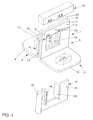
- the striker generally designated 1 essentially, that is, in terms of its basic components, of two Angle profiles 2 and 3, one leg 4 and 5 of which have free end regions 6 and 7, which lie flat on top of one another and welded in this exemplary embodiment (welding spots 8) are, while the other legs 9 and 10 of the angle profiles 2 and 3 in one plane run and to attach to a vehicle pillar, in this case by screws, are trained.
- the gap 38 also serves to receive the Main area 41 of the plastic cover 42, which, as already described, either prefabricated profile part or at the location of one leg 32 and 33 of the angle profiles 30 and 31 can be made and applied by injection molding.
- the recoveries 43 and 44 of the free ones obtained through the bends 34 and 35 End regions 36 and 37 in turn serve to accommodate the side walls of one Plastic cap 45.
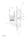
- the striker shown generally at 46 according to FIG 2 in use that is, in interaction with lock components, shows, thus recognizes one that the plastic cap 45 interacts with the catch bearing 47.
- This has the Lip 48 which is resiliently mounted on the rubber buffer 49.
- the upper area 49 of the Catch bearing 47 is based on or part of the door weight on the Plastic cap 45, so that there is contact between two plastic parts at this point.
Abstract
Description
Die Erfindung betrifft einen Schließbügel gemäß dem Oberbegriff des Patentanspruchs 1. In
erster Linie ist bei dem Schloss an ein Schloss zum Verriegeln einer Kraftfahrzeugtür
gedacht, jedoch lässt sich die Erfindung mit Vorteil auch in anderen Fällen einsetzen. Als
Sperrglied wird in der Regel eine Drehfalle vorgesehen sein, jedoch ist auch hier die
Erfindung in vorteilhafter Weise nicht auf den Einsatz bezüglich spezieller Konstruktionen
beschränkt.The invention relates to a striker according to the preamble of
Bleibt man zur Veranschaulichung der Erfindung bei dem bevorzugten Einsatzfall, nämlich einem Schloss zur Verriegelung einer Kraftfahrzeugtür, so befindet sich die üblicherweise als Sperrglied verwendete Drehfalle in ihrer Verriegelungsstellung, wenn sie die Eingriffsöffnung des Schließbügels mit einem Arm durchsetzt, und zugleich besteht dann bei dem gattungsgemäßen Schließbügel eine Berührung zwischen diesem und einem Fanglager. Drehfalle und Fanglager sind üblicherweise türseitig angeordnet, während der Schließbügel beispielsweise an der B-Säule des Kraftfahrzeugs befestigt ist. Die Berührung zwischen Fanglager und Schließbügel kann dabei erheblichen Kräften ausgesetzt sein, insbesondere dann, wenn die Konstruktion so getroffen ist, dass über das Fanglager dann eine Abstützung der Tür erfolgt. Zur Vermeidung von metallischem Kontakt an dieser Stelle ist es bekannt, das Fanglager zumindest oberflächlich aus einem Kunststoff herzustellen.To illustrate the invention, the preferred application, namely a lock for locking a motor vehicle door, it is usually located as Locking member used rotary latch in its locked position when opening the engaging opening of the striker with one arm, and at the same time there is generic striker a contact between this and a backup bearing. The catch and catch bearing are usually arranged on the door side, during the striker for example, is attached to the B-pillar of the motor vehicle. The touch between Catch bearing and striker can be exposed to considerable forces, in particular when the construction is made in such a way that there is a support over the safety bearing the door is done. To avoid metallic contact at this point it is known to manufacture the catch bearing at least superficially from a plastic.
Wie sich gezeigt hat, kann es im Betrieb bei derartigen Konstruktionen zu Knarzgäuschen kommen, die, wie die erfindungsgemäß angestellten Untersuchungen gezeigt haben, ihre Ursache in dem beschriebenen Kontakt zwischen Fanglager einerseits und Schließbügel andererseits haben.As has been shown, there can be creaking noises in operation with such constructions come who, as the investigations according to the invention have shown, their Cause in the described contact between the safety bearing on the one hand and the locking bracket on the other hand.
Zur Vermeidung von störenden Geräuschen durch die Berührung zwischen einer Drehfalle einerseits und einem Schließbügel oder Schließbolzen andererseits ist es bekannt, beide Teile in ihren an diesen Berührungen teilnehmenden Zonen mit einem Kunststoff zu beschichten, so dass dort die Kontakte zwischen Kunststoffflächen beziehungsweise Kunststoffzonen erfolgen. Wollte man diese Lösung ohne weiteres auf die hier interessierende Vermeidung einer Geräuschentwicklung durch Kontakte zwischen Schließbügel und Fanglager anwenden, so würde der Schließbügel aufgrund des Vorsehens von Zonen aus Kunststoff auf seiner Oberfläche größere Abmessungen als bisher erhalten. Eine Vergrößerung der Abmessungen ist aber unerwünscht, weil damit zwangsläufig auch eine Vergrößerung der Abmessungen einer Ausnehmung im Schlossgehäuse verbunden wäre, man aber bestrebt ist, die Verhältnisse im Bereich des Schlosses möglichst raumsparend zu gestalten.To avoid disturbing noises caused by the contact between a rotary latch on the one hand and a striker or striker on the other hand, both are known Allocate in their zones participating in these touches with a plastic coat so that there are the contacts between plastic surfaces respectively Plastic zones are made. If you wanted this solution to the here Interesting avoidance of noise through contacts between To use the striker and safety catch, the striker would be due to the provision obtained from plastic zones on its surface larger dimensions than previously. However, increasing the dimensions is undesirable because it is inevitable an increase in the dimensions of a recess in the lock housing connected would, but one strives, the conditions in the area of the castle as possible space-saving design.
Der Erfindung liegt mithin die Aufgabe zugrunde, einen gattungsgemäßen Schließbügel zu schaffen, bei dem die beschriebene Neigung zu Knarzgeräuschen ohne Vergrößerung seiner Abmessungen zumindest erheblich verringert ist.The invention is therefore based on the object of a generic locking bracket create, in which the described tendency to creak noises without magnification its dimensions are at least significantly reduced.
Die erfindungsgemäße Lösung dieser Aufgabe besteht in den kennzeichnenden Merkmalen des Hauptanspruchs, vorteilhafte Ausbildungen der Erfindung beschreiben die Unteransprüche.The achievement of this task consists in the characteristic features of the main claim, advantageous embodiments of the invention describe the Subclaims.
Wesentlich für die Erfindung ist also nicht nur die Tatsache, dass die freien Endbereiche der beiden Winkelprofile, die den wesentlichen Bestandteil des Schließbügels bilden, mit einer Kunststoffkappe versehen sind, sondern dass die beiden parallel zueinander verlaufenden einen Schenkel beider Winkelprofile mit in Richtung aufeinander abgekröpften Endbereichen versehen sind, wodurch einerseits zwischen den übrigen Bereichen der Winkelprofile ein Spalt zur Aufnahme des Hauptbereichs der Kunststoffverkleidung gebildet wird, andererseits - infolge Beibehalts der Materialstärke des Flachmaterials der Winkelprofile - die Endbereiche seitliche Einziehungen gegenüber den restlichen Bereichen dieser Schenkel bilden, die zur Unterbringung der Kunststoffkappe ausgenutzt werden. Im Endergebnis vergrößert also diese Kunststoffkappe die Abmessungen des Schließbügels nicht. Auch die übrigen Eigenschaften des Schließbügels werden in keiner Weise durch die erfindungsgemäßen Maßnahmen beeinträchtigt.It is therefore not only essential for the invention that the free end regions of the two angle profiles, which form the essential part of the striker, with one Plastic cap are provided, but that the two are parallel to each other one leg of both angle profiles with end areas bent towards each other are provided, whereby on the one hand between the other areas of the angle profiles Gap for receiving the main area of the plastic cladding is formed, on the other hand - As a result of maintaining the material thickness of the flat material of the angle profiles - the End areas lateral indentations compared to the remaining areas of these legs form, which are used to accommodate the plastic cap. In the end result So this plastic cap does not increase the dimensions of the striker. Also the other properties of the striker are in no way by the Measures according to the invention impaired.
Dabei bietet die Erfindung die vorteilhafte Möglichkeit, die Kunststoffverkleidung und/oder die Kunststoffkappe entweder als eigenständige Profilteile herzustellen und als solche in die Winkelprofile einzubauen oder aber zunächst die Winkelprofile durch Verbindung ihrer freien Endbereiche zu einem Teil zusammenzufügen und dann ihre einen Schenkel in eine Form einzubringen, in der durch Umspritzen die Kunststoffverkleidung und/oder die Kunststoffkappe hergestellt werden.The invention offers the advantageous possibility of plastic cladding and / or to manufacture the plastic cap either as independent profile parts and as such in the Install angle profiles or first the angle profiles by connecting their free ones Join end portions into one part and then shape one leg into one bring in, by overmolding the plastic cladding and / or Plastic cap are made.
An dieser Stelle sei eingefügt, dass unter einer "Verbindung" zwischen den beiden freien Endbereichen sowohl eine Verbindung von zwei selbstständige Teile darstellenden Winkelprofilen, beispielsweise durch Schweißen, verstanden sein soll als auch eine einteilige Ausbildung beider Winkelprofile dadurch, dass sie aus einem einzigen Materialstück durch Biegen hergestellt werden; die Biegekante findet sich dann an den freien Endbereichen.At this point it should be inserted that under a "connection" between the two free End areas both represent a connection of two independent parts Angle profiles, for example by welding, should be understood as well as a one-piece Formation of both angle profiles in that they are made from a single piece of material Bending are manufactured; the bending edge is then found at the free end areas.
Zwei Ausführungsbeispiele der Erfindung werden im Folgenden anhand der Zeichnung erläutert, deren Figuren 1 und 2 perspektivisch in Explosionsdarstellung zwei verschiedene Ausführungsformen des Schließbügels wiedergeben, während Figur 3 einen senkrechten Schnitt durch den Schließbügel bei geschlossener Fahrzeugtür zeigt.Two exemplary embodiments of the invention are described below with reference to the drawing explained, the figures 1 and 2 in perspective exploded view two different Play embodiments of the striker, while Figure 3 is a vertical Section through the striker with the vehicle door closed shows.
Betrachtet man zunächst Figur 1, so besteht der allgemein mit 1 bezeichnete Schließbügel
im Wesentlichen, das heißt was seine tragenden Bestandteile anbelangt, aus zwei
Winkelprofilen 2 und 3, deren eine Schenkel 4 und 5 freie Endbereiche 6 und 7 aufweisen,
die flach aufeinander liegen und in diesem Ausführungsbeispiel verschweißt (Schweißpunkte
8) sind, während die anderen Schenkel 9 und 10 der Winkelprofile 2 und 3 in einer Ebene
verlaufen und zum Befestigen an einer Fahrzeugsäule, in diesem Falle durch Schrauben,
ausgebildet sind.Looking first at Figure 1, there is the striker generally designated 1
essentially, that is, in terms of its basic components, of two
Betrachtet man aber zunächst wieder die einen Schenkel 4 und 5, so erkennt man, dass die
bereits erwähnten freien Endbereiche 6 und 7 aufeinander zu abgekröpft sind; die
Kröpfungen sind bei 11 und 12 dargestellt. Sie verlaufen in Höhe der oberen
Begrenzungskante der Ausnehmung 13 in beiden Schenkeln 4 und 5, die zum Eingriff einer
nicht dargestellten Drehfalle im verriegelten Zustand der Tür dient.But if you first look at one
Diese Abkröpfungen 11 und 12 haben zur Folge, dass zwischen den verbleibenden
Bereichen der Schenkel 4 und 5 ein Spalt 14 verbleibt, der zur Unterbringung des
Hauptbereichs 16 der allgemein mit 17 bezeichneten Kunststoffverkleidung für diejenigen
Flächen der Winkelprofile 2 und 3 dient, die in Berührung mit der Drehfalle kommen können.
Dazu ist der Bereich 16 mit leistenartigen Bereichen 18, 19 und 20 versehen, die einerseits
großflächige Berührungsflächen für die Drehfalle bieten und andererseits eine
formschlüssige Sicherung der Kunststoffverkleidung 17 in dem durch die Winkelprofile 2 und
3 gebildeten rahmenartigen Teil sicherstellen.These
An dieser Stelle sei eingefügt, dass die Kunststoffverkleidung 17 als vorgefertigtes Profilteil
angeliefert und vor dem Verbinden der freien Schenkelbereiche 6 und 7 dort positioniert sein
kann; andererseits ist es aber auch möglich, erst die besagten Verbindungen 8 herzustellen
und dann die einen Schenkel 4 und 5 in eine Form einzubringen, wo sie in einem
Spritzvorgang mit der Verkleidung 17 versehen werden. At this point it should be inserted that the
Dies gilt auch für die Herstellung beziehungsweise Aufbringung der Kunststoffkappe 21 auf
die freien Endbereiche 6 und 7. Durch die Abstellungen 11 und 12 und das Vorsehen
gleicher Materialstärken für die freien Endbereiche 6 und 7 einerseits und die übrigen
Bereiche der einen Schenkel 4 und 5 andererseits entstehen beiderseits der freien
Endbereiche 6 und 7 Einziehungen 22 und 23, die zur Aufnahme der Seitenwände der
Kunststoffkappe 21 ausgenutzt werden. Dadurch ist eine Verbreiterung der durch die einen
Schenkel 4 und 5 gebildeten Anordnung vermieden.This also applies to the manufacture or application of the
Während in dem Ausführungsbeispiel nach Figur 1 die beiden Winkelprofile 2 und 3 durch
Schweißverbindungen 8 miteinander verbunden sind, erfolgt diese Verbindung in dem
Ausführungsbeispiel nach Figur 2 durch einen Biegeprozess an einem einteiligen
Materialstück. Man erkennt wieder die beiden Winkelprofile 30 und 31 mit ihren einen
Schenkeln 32 und 33, die bei 34 und 35 aufeinander zu abgekröpft sind, so dass ihre freien
Endbereiche 36 und 37 wieder aufeinander liegen, dagegen die übrigen Bereiche den Spalt
38 einschließen. Die freien Endbereiche 36 und 37 sind durch den Biegebereich oder die
Biegekante 39 miteinander verbunden. Auch hier ist eine Ausnehmung 40 zum Eingriff einer
nicht dargestellten Sperrklinke vorgesehen; der Spalt 38 dient auch hier zur Aufnahme des
Hauptbereichs 41 der Kunststoffverkleidung 42, die, wie bereits beschrieben, entweder ein
vorgefertigtes Profilteil oder aber am Ort der einen Schenkel 32 und 33 der Winkelprofile 30
und 31 durch einen Spritzvorgang hergestellt und angebracht sein kann.While in the embodiment of Figure 1, the two
Die durch die Abkröpfungen 34 und 35 gewonnenen Einziehungen 43 und 44 der freien
Endbereiche 36 und 37 dienen wiederum zur Unterbringung der Seitenwände einer
Kunststoffkappe 45.The
Die Kunststoffkappe 21 in Figur 1 ist mit Fingern oder dergleichen 24 zum Eingriff in
Ausnehmungen 25 in den einen Schenkeln 4 und 5 versehen. Entsprechende Einrichtungen
zur Arretierung können auch für die Kunststoffkappe 45 in Figur 2 vorgesehen sein.The
Betrachtet man nun Figur 3, die den allgemein mit 46 bezeichneten Schließbügel nach Figur
2 im Einsatz, das heißt im Zusammenwirken mit Schlossbestandteilen, zeigt, so erkennt
man, dass die Kunststoffkappe 45 zusammenwirkt mit dem Fanglager 47. Dieses besitzt die
Lippe 48, die über den Gummipuffer 49 nachgiebig gelagert ist. Der obere Bereich 49 des
Fanglagers 47 stützt sich beziehungsweise einen Teil des Türgewichts ab auf der
Kunststoffkappe 45, so dass an dieser Stelle Kontakt zwischen zwei Kunststoffteilen vorliegt. If one now considers FIG. 3, the striker shown generally at 46 according to FIG
2 in use, that is, in interaction with lock components, shows, thus recognizes
one that the
Von den aktiven Teilen des Schlosses ist bei 50 die Drehfalle angedeutet, die mit einem Arm
die in Figur 2 mit 40 bezeichnete Ausnehmung in den einen Schenkeln 32 und 33
durchsetzt. Während das Schloss türseitig angeordnet ist, ist der Schließbügel 46 an der
fahrzeugseitigen Türsäule 51 befestigt.Of the active parts of the castle, the rotary latch is indicated at 50, that with one arm
the recess designated 40 in FIG. 2 in one
Mit der Erfindung ist also mit einfachen Mitteln ein gattungsgemäßer Schließbügel geschaffen, der hinsichtlich seiner Neigung zu Knarzgeräuschen optimiert ist.With the invention is a generic striker with simple means created, which is optimized in terms of its tendency to creaking noises.
Claims (7)
Applications Claiming Priority (2)
| Application Number | Priority Date | Filing Date | Title |
|---|---|---|---|
| DE10012750 | 2000-03-16 | ||
| DE10012750A DE10012750A1 (en) | 2000-03-16 | 2000-03-16 | Striker with an opening for a locking member of a lock |
Publications (2)
| Publication Number | Publication Date |
|---|---|
| EP1134334A1 true EP1134334A1 (en) | 2001-09-19 |
| EP1134334B1 EP1134334B1 (en) | 2003-08-13 |
Family
ID=7634904
Family Applications (1)
| Application Number | Title | Priority Date | Filing Date |
|---|---|---|---|
| EP01250057A Expired - Lifetime EP1134334B1 (en) | 2000-03-16 | 2001-02-22 | Striker assembly with an opening for a lock bolt element |
Country Status (3)
| Country | Link |
|---|---|
| EP (1) | EP1134334B1 (en) |
| AT (1) | ATE247210T1 (en) |
| DE (2) | DE10012750A1 (en) |
Cited By (5)
| Publication number | Priority date | Publication date | Assignee | Title |
|---|---|---|---|---|
| EP1408181A2 (en) * | 2002-10-11 | 2004-04-14 | ArvinMeritor Light Vehicle Systems (UK) Ltd | Latch assembly and striker |
| GB2461787A (en) * | 2008-07-10 | 2010-01-20 | Mitsui Mining & Smelting Co | A vehicle lock striker formed by bending a single plate |
| US20150014999A1 (en) * | 2013-07-12 | 2015-01-15 | Tachi-S Co., Ltd. | Striker for use with vehicle |
| EP2270295A3 (en) * | 2009-06-29 | 2017-02-22 | Kiekert Aktiengesellschaft | Striker in the form of a cut sheet metal |
| US20180252008A1 (en) * | 2015-08-28 | 2018-09-06 | Kiekert Ag | Lock holder for a motor vehicle lock |
Families Citing this family (1)
| Publication number | Priority date | Publication date | Assignee | Title |
|---|---|---|---|---|
| DE102009032894A1 (en) * | 2009-07-13 | 2011-01-20 | Kiekert Ag | Lock for a door or a flap on a motor vehicle |
Citations (3)
| Publication number | Priority date | Publication date | Assignee | Title |
|---|---|---|---|---|
| US4165112A (en) * | 1977-06-04 | 1979-08-21 | Arn. Kiekert Sohne | Motor-vehicle door latch |
| EP0272116A1 (en) * | 1986-12-17 | 1988-06-22 | Magna International Inc. | Striker, latch housing and locking mechanism for a vehicle door |
| DE4224145A1 (en) * | 1992-07-22 | 1994-01-27 | Bocklenberg & Motte Bomoro | Shock absorber mfr. in two part injection moulding method - giving two areas of different hardness produced using different material |
Family Cites Families (7)
| Publication number | Priority date | Publication date | Assignee | Title |
|---|---|---|---|---|
| DE2218734C3 (en) * | 1972-04-18 | 1978-03-23 | Arn. Kiekert Soehne, 5628 Heiligenhaus | Motor vehicle door lock |
| DE2936997C2 (en) * | 1979-09-13 | 1983-11-17 | Tack & Gabel GmbH & Co KG, 5600 Wuppertal | Locking bolt for a motor vehicle door lock with fork latch |
| DE3623311A1 (en) * | 1986-07-11 | 1988-01-21 | Kiekert Gmbh Co Kg | LOCKING BLOCK FOR A MOTOR VEHICLE DOOR LOCK AND METHOD FOR THE PRODUCTION THEREOF |
| DE8710288U1 (en) * | 1987-07-28 | 1987-09-17 | Kiekert Gmbh & Co Kg, 5628 Heiligenhaus, De | |
| DE3809317A1 (en) * | 1988-03-19 | 1989-10-05 | Ymos Ag Ind Produkte | DOOR LOCK |
| DE19540571C2 (en) * | 1994-11-11 | 2000-11-16 | Volkswagen Ag | Locking device |
| DE19742766C2 (en) * | 1997-09-27 | 1999-08-12 | Bosch Gmbh Robert | Locking block for a motor vehicle locking device |
-
2000
- 2000-03-16 DE DE10012750A patent/DE10012750A1/en not_active Ceased
-
2001
- 2001-02-22 EP EP01250057A patent/EP1134334B1/en not_active Expired - Lifetime
- 2001-02-22 AT AT01250057T patent/ATE247210T1/en not_active IP Right Cessation
- 2001-02-22 DE DE50100474T patent/DE50100474D1/en not_active Expired - Lifetime
Patent Citations (3)
| Publication number | Priority date | Publication date | Assignee | Title |
|---|---|---|---|---|
| US4165112A (en) * | 1977-06-04 | 1979-08-21 | Arn. Kiekert Sohne | Motor-vehicle door latch |
| EP0272116A1 (en) * | 1986-12-17 | 1988-06-22 | Magna International Inc. | Striker, latch housing and locking mechanism for a vehicle door |
| DE4224145A1 (en) * | 1992-07-22 | 1994-01-27 | Bocklenberg & Motte Bomoro | Shock absorber mfr. in two part injection moulding method - giving two areas of different hardness produced using different material |
Cited By (9)
| Publication number | Priority date | Publication date | Assignee | Title |
|---|---|---|---|---|
| EP1408181A2 (en) * | 2002-10-11 | 2004-04-14 | ArvinMeritor Light Vehicle Systems (UK) Ltd | Latch assembly and striker |
| EP1408181A3 (en) * | 2002-10-11 | 2006-06-14 | ArvinMeritor Light Vehicle Systems (UK) Ltd | Latch assembly and striker |
| GB2461787A (en) * | 2008-07-10 | 2010-01-20 | Mitsui Mining & Smelting Co | A vehicle lock striker formed by bending a single plate |
| GB2461787B (en) * | 2008-07-10 | 2010-10-06 | Mitsui Mining & Smelting Co | Vehicle lock striker |
| EP2270295A3 (en) * | 2009-06-29 | 2017-02-22 | Kiekert Aktiengesellschaft | Striker in the form of a cut sheet metal |
| US20150014999A1 (en) * | 2013-07-12 | 2015-01-15 | Tachi-S Co., Ltd. | Striker for use with vehicle |
| US9499070B2 (en) * | 2013-07-12 | 2016-11-22 | Tachi-S Co., Ltd. | Striker for use with vehicle |
| US20180252008A1 (en) * | 2015-08-28 | 2018-09-06 | Kiekert Ag | Lock holder for a motor vehicle lock |
| US11035158B2 (en) * | 2015-08-28 | 2021-06-15 | Kiekert Ag | Lock holder for a motor vehicle lock |
Also Published As
| Publication number | Publication date |
|---|---|
| EP1134334B1 (en) | 2003-08-13 |
| DE50100474D1 (en) | 2003-09-18 |
| DE10012750A1 (en) | 2001-09-20 |
| ATE247210T1 (en) | 2003-08-15 |
Similar Documents
| Publication | Publication Date | Title |
|---|---|---|
| DE102006019959B4 (en) | Tank flap for automobiles | |
| EP0380013B1 (en) | Device for fastening a roof liner to the construction of a sliding sun roof of a sliding pivoting sun roof | |
| EP2640916B1 (en) | Lock having a modified spring lip for motor vehicle doors | |
| DE2735787A1 (en) | GUIDE ELEMENT FOR RESILIENTLY BEARING SLIDING DOOR ELEMENTS AND SLIDING DOOR ELEMENT EQUIPPED WITH IT | |
| DE10064017A1 (en) | Device for connecting a carrier, in particular a body part of a motor vehicle, to a plate element, in particular a door or wall covering | |
| WO2007017329A1 (en) | Modular container for refrigerated products | |
| EP1379820A1 (en) | Storage container for refrigerators | |
| EP1354545B1 (en) | Sealing for a shower partition | |
| DE10042087A1 (en) | Bracket for mounting car wing is L-shaped, one arm being attached to wing and other being snap-fitted on to upright, latches on either side of arm containing spring components which lock them into slots on upright | |
| EP1134334B1 (en) | Striker assembly with an opening for a lock bolt element | |
| DE19742766A1 (en) | Locking block for a motor vehicle locking device | |
| EP1621407A1 (en) | Connection clip for a vehicle trim element. | |
| DE2856493A1 (en) | TRIM CLAMP | |
| DE2524419C2 (en) | Hinge for attaching a glass door to a furniture body | |
| EP1926952B1 (en) | Door for a refrigerator | |
| DE3640012A1 (en) | TWO-PIECE CONNECTING FITTING | |
| DE3602674A1 (en) | Snap-lock device | |
| EP1119464A1 (en) | Valve, especially an air entry and air exit ventilation valve for the passenger compartment of a motor vehicle | |
| DE202016007457U1 (en) | Rotary bolt lock | |
| EP0846595B1 (en) | Plastic assembly, particularly for vehicles. | |
| DE60309374T2 (en) | Door handle, especially for vehicles | |
| AT7647U1 (en) | CONNECTION FITTING FOR DRAWER WALLS | |
| DE202012102709U1 (en) | Building panel with a device for connection to at least one further building panel on a substrate | |
| EP3711990B1 (en) | Connecting element with two independent holding devices | |
| DE4018771A1 (en) | Hinge securing component on bracket - has spindle on pivoting component secured in bracket bearings accessible from outside |
Legal Events
| Date | Code | Title | Description |
|---|---|---|---|
| PUAI | Public reference made under article 153(3) epc to a published international application that has entered the european phase |
Free format text: ORIGINAL CODE: 0009012 |
|
| AK | Designated contracting states |
Kind code of ref document: A1 Designated state(s): AT BE CH CY DE DK ES FI FR GB GR IE IT LI LU MC NL PT SE TR |
|
| AX | Request for extension of the european patent |
Free format text: AL;LT;LV;MK;RO;SI |
|
| 17P | Request for examination filed |
Effective date: 20020319 |
|
| AKX | Designation fees paid |
Free format text: AT BE CH CY DE DK ES FI FR GB GR IE IT LI LU MC NL PT SE TR |
|
| GRAH | Despatch of communication of intention to grant a patent |
Free format text: ORIGINAL CODE: EPIDOS IGRA |
|
| GRAH | Despatch of communication of intention to grant a patent |
Free format text: ORIGINAL CODE: EPIDOS IGRA |
|
| GRAA | (expected) grant |
Free format text: ORIGINAL CODE: 0009210 |
|
| STAA | Information on the status of an ep patent application or granted ep patent |
Free format text: STATUS: THE PATENT HAS BEEN GRANTED |
|
| AK | Designated contracting states |
Designated state(s): AT BE CH CY DE DK ES FI FR GB GR IE IT LI LU MC NL PT SE TR |
|
| PG25 | Lapsed in a contracting state [announced via postgrant information from national office to epo] |
Ref country code: IT Free format text: LAPSE BECAUSE OF FAILURE TO SUBMIT A TRANSLATION OF THE DESCRIPTION OR TO PAY THE FEE WITHIN THE PRESCRIBED TIME-LIMIT;WARNING: LAPSES OF ITALIAN PATENTS WITH EFFECTIVE DATE BEFORE 2007 MAY HAVE OCCURRED AT ANY TIME BEFORE 2007. THE CORRECT EFFECTIVE DATE MAY BE DIFFERENT FROM THE ONE RECORDED. Effective date: 20030813 Ref country code: NL Free format text: LAPSE BECAUSE OF FAILURE TO SUBMIT A TRANSLATION OF THE DESCRIPTION OR TO PAY THE FEE WITHIN THE PRESCRIBED TIME-LIMIT Effective date: 20030813 Ref country code: CY Free format text: LAPSE BECAUSE OF FAILURE TO SUBMIT A TRANSLATION OF THE DESCRIPTION OR TO PAY THE FEE WITHIN THE PRESCRIBED TIME-LIMIT Effective date: 20030813 Ref country code: TR Free format text: LAPSE BECAUSE OF FAILURE TO SUBMIT A TRANSLATION OF THE DESCRIPTION OR TO PAY THE FEE WITHIN THE PRESCRIBED TIME-LIMIT Effective date: 20030813 Ref country code: IE Free format text: LAPSE BECAUSE OF FAILURE TO SUBMIT A TRANSLATION OF THE DESCRIPTION OR TO PAY THE FEE WITHIN THE PRESCRIBED TIME-LIMIT Effective date: 20030813 Ref country code: GB Free format text: LAPSE BECAUSE OF FAILURE TO SUBMIT A TRANSLATION OF THE DESCRIPTION OR TO PAY THE FEE WITHIN THE PRESCRIBED TIME-LIMIT Effective date: 20030813 Ref country code: FI Free format text: LAPSE BECAUSE OF FAILURE TO SUBMIT A TRANSLATION OF THE DESCRIPTION OR TO PAY THE FEE WITHIN THE PRESCRIBED TIME-LIMIT Effective date: 20030813 Ref country code: ES Free format text: LAPSE BECAUSE OF FAILURE TO SUBMIT A TRANSLATION OF THE DESCRIPTION OR TO PAY THE FEE WITHIN THE PRESCRIBED TIME-LIMIT Effective date: 20030813 |
|
| REG | Reference to a national code |
Ref country code: GB Ref legal event code: FG4D Free format text: NOT ENGLISH |
|
| REG | Reference to a national code |
Ref country code: CH Ref legal event code: EP |
|
| REG | Reference to a national code |
Ref country code: IE Ref legal event code: FG4D Free format text: GERMAN |
|
| REF | Corresponds to: |
Ref document number: 50100474 Country of ref document: DE Date of ref document: 20030918 Kind code of ref document: P |
|
| PG25 | Lapsed in a contracting state [announced via postgrant information from national office to epo] |
Ref country code: GR Free format text: LAPSE BECAUSE OF FAILURE TO SUBMIT A TRANSLATION OF THE DESCRIPTION OR TO PAY THE FEE WITHIN THE PRESCRIBED TIME-LIMIT Effective date: 20031113 Ref country code: DK Free format text: LAPSE BECAUSE OF FAILURE TO SUBMIT A TRANSLATION OF THE DESCRIPTION OR TO PAY THE FEE WITHIN THE PRESCRIBED TIME-LIMIT Effective date: 20031113 Ref country code: SE Free format text: LAPSE BECAUSE OF FAILURE TO SUBMIT A TRANSLATION OF THE DESCRIPTION OR TO PAY THE FEE WITHIN THE PRESCRIBED TIME-LIMIT Effective date: 20031113 |
|
| PG25 | Lapsed in a contracting state [announced via postgrant information from national office to epo] |
Ref country code: PT Free format text: LAPSE BECAUSE OF FAILURE TO SUBMIT A TRANSLATION OF THE DESCRIPTION OR TO PAY THE FEE WITHIN THE PRESCRIBED TIME-LIMIT Effective date: 20040113 |
|
| NLV1 | Nl: lapsed or annulled due to failure to fulfill the requirements of art. 29p and 29m of the patents act | ||
| GBV | Gb: ep patent (uk) treated as always having been void in accordance with gb section 77(7)/1977 [no translation filed] |
Effective date: 20030813 |
|
| PG25 | Lapsed in a contracting state [announced via postgrant information from national office to epo] |
Ref country code: AT Free format text: LAPSE BECAUSE OF NON-PAYMENT OF DUE FEES Effective date: 20040222 Ref country code: LU Free format text: LAPSE BECAUSE OF NON-PAYMENT OF DUE FEES Effective date: 20040222 |
|
| PG25 | Lapsed in a contracting state [announced via postgrant information from national office to epo] |
Ref country code: MC Free format text: LAPSE BECAUSE OF NON-PAYMENT OF DUE FEES Effective date: 20040228 Ref country code: BE Free format text: LAPSE BECAUSE OF NON-PAYMENT OF DUE FEES Effective date: 20040228 |
|
| REG | Reference to a national code |
Ref country code: IE Ref legal event code: FD4D |
|
| ET | Fr: translation filed | ||
| PLBE | No opposition filed within time limit |
Free format text: ORIGINAL CODE: 0009261 |
|
| STAA | Information on the status of an ep patent application or granted ep patent |
Free format text: STATUS: NO OPPOSITION FILED WITHIN TIME LIMIT |
|
| 26N | No opposition filed |
Effective date: 20040514 |
|
| BERE | Be: lapsed |
Owner name: *VOLKSWAGEN A.G. Effective date: 20040228 |
|
| PG25 | Lapsed in a contracting state [announced via postgrant information from national office to epo] |
Ref country code: LI Free format text: LAPSE BECAUSE OF NON-PAYMENT OF DUE FEES Effective date: 20050228 Ref country code: CH Free format text: LAPSE BECAUSE OF NON-PAYMENT OF DUE FEES Effective date: 20050228 |
|
| REG | Reference to a national code |
Ref country code: CH Ref legal event code: PL |
|
| PGFP | Annual fee paid to national office [announced via postgrant information from national office to epo] |
Ref country code: FR Payment date: 20100222 Year of fee payment: 10 |
|
| PGFP | Annual fee paid to national office [announced via postgrant information from national office to epo] |
Ref country code: DE Payment date: 20100228 Year of fee payment: 10 |
|
| REG | Reference to a national code |
Ref country code: FR Ref legal event code: ST Effective date: 20111102 |
|
| REG | Reference to a national code |
Ref country code: DE Ref legal event code: R119 Ref document number: 50100474 Country of ref document: DE Effective date: 20110901 |
|
| PG25 | Lapsed in a contracting state [announced via postgrant information from national office to epo] |
Ref country code: FR Free format text: LAPSE BECAUSE OF NON-PAYMENT OF DUE FEES Effective date: 20110228 |
|
| PG25 | Lapsed in a contracting state [announced via postgrant information from national office to epo] |
Ref country code: DE Free format text: LAPSE BECAUSE OF NON-PAYMENT OF DUE FEES Effective date: 20110901 |